2 Engine Nozzles, 1 cockpit nozzle. FX G-TEC 2900R3 FIA standard Advanced 8865 Discharge System
|
|
|
- Ellen Brooks
- 5 years ago
- Views:
Transcription
1 Fire Extinguisher System Manual for FIA Standard Engine Nozzles, 1 cockpit nozzle. FX G-TEC 2900R3 FIA standard Advanced 8865 Discharge System Please read all parts of this manual carefully before you proceed to install your new purchase. The system has been carefully developed to meet the new standard which is part of the FIA s new program in making Motorsport a much safer sport for all who take part. The new standard has been designed to meet much tougher criteria, testing with much larger and hotter fires with greater quantities of fuels together with plastics and masking elements to extinguish. In this new standard electrical components are now IP rated and other parts have been vigorously tested to meet certain BSI standards. FIA It must be emphasised that any plumbed in fire extinguisher system is mainly designed to delay the development of the fire and consequently give the driver and co-driver time to exit the car; the system is not designed to put out the fire and prevent the car from burning. Please do not tamper with, make changes or use non FEV parts on your new fire extinguisher system as this will invalidate the Homologation and affect the performance of the product. If any new parts are needed please call FEV on 0044 (0) You will have to purchase a9 volt PP3 battery for the control box. Also if any changes have been made to this product from the specification, it could in effect stop you racing.
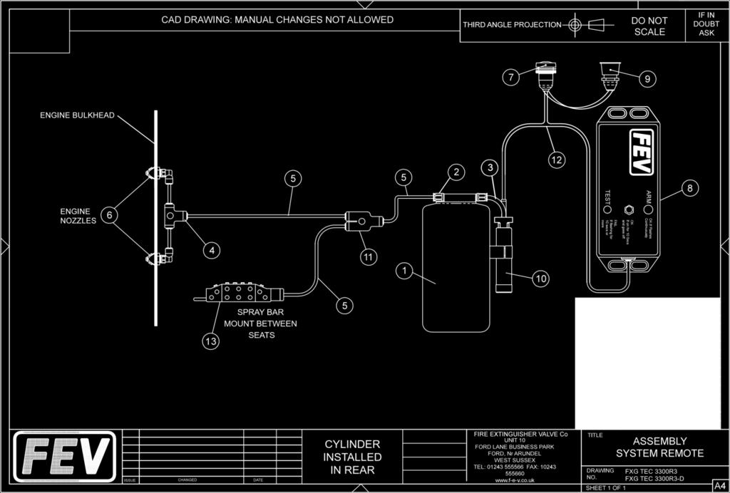
2 Contents. 2 Plumbing schematic drawings 1 Installation instructions 1 cylinder FE-CYL-2900R - Long cylinder 101mm x 403mm FE-CYL-2900R-D - Dumpy cylinder 127mm x 263mm 2 Cradle straps FE-CRL-S Hard-line hose FE-H-HOS 1 33 gram remote charge FE-REM-33-CHAR 1 Remote clamp FE-REM-C Remote clamps bolts FE-REM-C-B mtr of 8mm Aluminium tubing FE-ALI pipe clips FE-P-CLIPS 1 Cockpit bar nozzles FE-16-JET BAR-NOZ-1.1R 2 Engine tri nozzles black FE-TRI-NOZ-1.5-B 1 Y connector 8mm metal FE-Y-CON-8-M cylinder installed in the rear 1 T connector 8mm metal FE-T-CON-8-8-M cylinder installed in the front 1 T connector 8mm metal FE-T-CON-8-8-M standard engine connector 1 Straight connector 8mm FE-ST-CON-8 optional mm stem FE-90-8-ST optional 1 internal firing button FE-INT-FB 1 fire button metal shroud FE-INT-FB-S-M 1 External fire button FE-EXT-FB 1 Control box 8865 V2 FE-CB-8865, Red control box, battery not included. 1 Control box loom FE-CB-L-8865
3 Installation of cylinder and other components. Cylinder. Find a suitable place either behind the drivers or co-driver s seat or in the co driver s footwell to fix the fire extinguisher cylinder, the cylinder assembly can be fixed either in a transverse or longitude position. There is no need to take the cylinder out of the cradle bracket and straps as the cylinder comes already installed into the cradle bracket. The newly designed cradle bracket has access to the four fixing holes and only needs marking through onto the car floor where you want to fix the assembly. Once the markings have been made put the assembly to one side then carefully drill holes for 4 off fixing bolts we recommend M6 bolts with shake-proof washers and Nyloc nuts, bolt the cylinder assembly to the floor. Please note the system must be installed in accordance with the championship technical regulation. Plumbing connectors Please note that if the cylinder is going to be installed in the front foot well or in the back of the car behind the driver or co driver s seat, 1 of the different connector must be used for front or back installation. See contents list. Cylinder Installed in Front See assembly drawing in the user manual. 2off Tee connectors Cylinder Installed in Rear See assembly drawing in the user manual. 1off Y connector, 1off Tee connector Optional connector One inline straight connector and 90 degree stem elbow can be used to aid installation if needed Cockpit nozzle The one cockpit 16 jet bar nozzle is designed to be fitted between the drivers and co driver s seat with the 10 jets facing forward and the 6 jets pointing upwards and just behind the two seats towards the roof. The nozzle should be fixed either on a preformed bracket, or by fixing a pipe clip supplied around the metal tubing close to the push in connector attached to the nozzle and fixed through the metal tab on the other end of the nozzle.
4 Engine nozzles. The two engine nozzles must be fitted through the cockpit/engine bulkhead approximately 30 centimetres each side of centre and as near to the top as possible (unless obstructed) in a horizontal position again unless obstructed, nozzle hole size 13.5mm. Aluminium tubing. The pipework for the system is Aluminium. Route the pipework neatly around the car to the different locations. When making bends in the piping try and make a minimum radius of 50mm, and when cutting the pipes make sure the ends are square or use a pipe cutter if possible and de-burr the ends, push all ends of the pipes into the various fittings, they should push in 18mm. See separate plumbing instructions for the complete plumbing schematics. Control box. Mount the control box in a suitable position where it can be reached by the driver and codriver, making sure that the LED lights are visible to the driver and co-driver. Please ensure that the wiring loom for the control box is fixed suitably so that it cannot be damaged or become a hazard. Wiring loom The wiring loom has two screw connectors; the connector on the longest length of cable is a two pin connector and connects to the plug on the remote charge which is attached to the fire extinguisher connect this lead last and make sure the control box is in the test position. The shorter length of cable with the three pin plug attached connects to the control box. The branch in the loom goes to the internal fire button, make a suitable connection. Using the separate (supplied) cable already attached to the external fire button fit the button externally then route the cable inside the car to attach to the connections of the internal fire button. Activation buttons. There are two activation buttons, one internal and one external. Mount the internal button in a position within easy reach for the driver and co-driver where applicable (19mm diameter hole), mount the external button (22mm) next to the electrical cut off switch. Apply the E decal label next to the external firing switch.


5 F.E.V. CONTROL BOX - V2 - FIA 8865 INSTRUCTIONS The control box is supplied with a separate wiring loom with a connector on each end; the longest length of wire has a male 2-pin IP67 rated plug for connection to the female 2 pin IP67 socket in the Remote Charge Cartridge, when connected they are screwed together to make a seal. The other end of the loom is fitted with a male 3 pin IP67 rated waterproof plug, this plug connects to the female 3 pin IP67 socket in the bottom of the control box and when connected they are screwed together to make a seal. The branch in the loom goes to the internal fire button, make a suitable connection. Using the separate (supplied) cable already attached to the external fire button fit the button externally then route the cable inside the car to attach to the connections of the internal fire button. Setting up The System The control box has a 2 position on-on toggle switch to select the function. The up position is ARM with a red LED and down position TEST with an orange LED. Test position LED orange To test the system put the switch into the TEST position and press either of the firing buttons external or internal. If the TEST is successful, the Orange LED will be on for 10 seconds. If the TEST is unsuccessful the Orange LED will flash for 10 seconds or more, indicating a fault in one of the following items low battery, electrical discontinuity, button to trigger the system, plug on the remote charge or firing actuator in the remote charge. Armed Position red LED Switch to the armed position - whenever the switch is moved from the test to the armed position, the control box will run an automatic test to ascertain that there is no anomaly, only after those checks will the LED start to flash continually indicating the control box is operational. Only press the fire button if needed, this will activate the system. Recommend after use. Whenever the control box is not in use position the switch into test mode all the lights are off - this will enable the control box to go into sleep mode and save battery. If the vehicle is not going to be used for a long period, we would recommend you remove the battery from the control box. Preparation for race Check all wiring connections and run through the test position procedure before each race to test for any anomaly. Battery fitment This control box is IP67 rated. This is why the box has to be removed from fitment and the four screws removed from the back of the box to replace the battery - battery type 9 volt PP3 alkaline

6
 Précaution à prendre lors de l installation du système Special care to take with the installation of the system E1-1) Installation dans l habitacle (emplacement")
7 101. INSTALLATION DANS L HABITACLE / COCKPIT INSTALLATION WITH CYLINDER AT FRONT a) Emplacement et orientation du corps Location and orientation of body b) Emplacement et orientation des buses Location and orientation of nozzles c) Précaution à prendre lors de l installation du système Special care to take with the installation of the system E1-1) Installation dans l habitacle (emplacement et orientation du corps) Cockpit installation (location and orientation of body) Mount horizontally in front of the passengers Seat, transversly or longditudinally. Located between passenger and drivers seats Make sure the nozzle is installed onto the floor with 10 jets facing forward and 6 jets pointing towards the roof just behind back of seats E1-2) Installation dans l habitacle (emplacement et orientation des buses) Cockpit installation (location and orientation of nozzles) 102. INSTALLATION DANS LE MOTEUR / ENGINE INSTALLATION a) Emplacement et orientation du corps Location and orientation of body b) Emplacement et orientation des buses Location and orientation of nozzles c) Précaution à prendre lors de l installation du système Special care to take with the installation of the system N/A Mount through bulkhead or on pre-formed brackets approximately 300mm each side of centre only move if obstructed. Check all connections are secure. E2-1) Installation dans le moteur (emplacement et orientation du corps) Engine installation (location and orientation of body) E2-2) Installation dans le moteur (emplacement et orientation des buses) Engine installation (location and orientation of nozzles)
FX G-TEC 3300R Advanced Discharge System (Long Cylinder) FX G-TEC 3300R-D Advanced Discharge System (Dumpy Cylinder)
 FX G-TEC 3300R-D Advanced Discharge System (Dumpy Cylinder)") Fire Extinguisher System Manual for FIA Standard 8865 FIA standard 8865 FX G-TEC 3300R Advanced Discharge System (Long Cylinder) FX G-TEC 3300R-D Advanced Discharge System (Dumpy Cylinder) Please read
Fire Extinguisher System Manual for FIA Standard 8865 FIA standard 8865 FX G-TEC 3300R Advanced Discharge System (Long Cylinder) FX G-TEC 3300R-D Advanced Discharge System (Dumpy Cylinder) Please read
FX G-TEC 2900R Advanced Discharge System (Long Cylinder) FX G-TEC 2900R-D Advanced Discharge System (Dumpy Cylinder)
 FX G-TEC 2900R-D Advanced Discharge System (Dumpy Cylinder)") Fire Extinguisher System Manual for FIA Standard 8865 FIA standard 8865 FX G-TEC 2900R Advanced Discharge System (Long Cylinder) FX G-TEC 2900R-D Advanced Discharge System (Dumpy Cylinder) Please read
Fire Extinguisher System Manual for FIA Standard 8865 FIA standard 8865 FX G-TEC 2900R Advanced Discharge System (Long Cylinder) FX G-TEC 2900R-D Advanced Discharge System (Dumpy Cylinder) Please read
FES1800EK. Electronic Plumbed-In Fire Extinguisher System Installation Instructions
 FESG1800E Electronic Plumbed-In Fire Extinguisher System Installation Instructions This is an FX G-TEC 1800E +ADS Advanced Discharge System - homologated gas fire extinguisher system. To maintain optimum
Technical Bulletin 016 Zero Installation Guide
 Technical Bulletin 016 Zero 36 2 0 Installation Guide Rev3 06/12/2016 The Lifeline Zero 36 20 extinguisher (UK Patent No. GB 2523902./UK Patent Application No. 1516832.1.) is homologated to FIA8865-2015
FESG1500R Remote Electronic Plumbed-In Fire Extinguisher System Installation Instructions
 FESG1500R Remote Electronic Plumbed-In Fire Extinguisher System Installation Instructions This is an FX G-TEC 1500R +ADS Advanced Discharge System - homologated gas fire extinguisher system. To maintain
Technical Bulletin 036 Zero FM m 3 & m 3 Installation Guide
 Technical Bulletin 036 Zero 36 2 0 FM 1.6-2.3m 3 & 2.3-4.03m 3 Installation Guide Rev2 16/05/2016 The Lifeline Zero 36 20 FM extinguisher range (UK Patent No. GB2523902; UK Patent Application No. GB 1516832.1)
FEDERATION INTERNATIONALE DE L AUTOMOBILE
 FEDERATION INTERNATIONALE DE L AUTOMOBILE 06.03.2017 FICHE DE PRESENTATION DES SYSTEMES D EXTINCTION FIXES (NORME FIA 8865-2015) PRESENTATION FORM FOR PLUMBED-IN FIRE EXTINGUISHER SYSTEMS (FIA STANDARD
FITTING INSTRUCTIONS
 FITTING INSTRUCTIONS All Zero 360 FIA Systems PLEASE READ CAREFULLY BEFORE ATTEMPTING TO INSTALL YOUR SYSTEM Lifeline Fire & Safety Systems Ltd 008 Thank you for purchasing a FIA approved Zero 360 Lifeline
FITTING INSTRUCTIONS
 FITTING INSTRUCTIONS All Zero ZERO FIA Systems PLEASE READ CAREFULLY BEFORE ATTEMPTING TO INSTALL YOUR SYSTEM Lifeline Fire & Safety Systems Ltd 008 Inst/ZEROzero.5kg/V/Aug08 Thank you for purchasing a
Technical Bulletin 012 Zero 2000 MSA & FIA Kit Content and Spares
 Technical Bulletin 012 Zero 2000 MSA & FIA Kit Content and Spares Rev2 07/12/2015 The tables below detail the contents of our Zero 2000 MSA and FIA plumbed-in systems Fitting Kits. Most items are available
FEDERATION INTERNATIONALE DE L AUTOMOBILE
 FEDERATION INTERNATIONALE DE L AUTOMOBILE Date 30.11.2015 FICHE DE PRESENTATION DES SYSTEMES D EXTINCTION FIXES (NORME FIA 8865-2015) PRESENTATION FORM FOR PLUMBED-IN FIRE EXTINGUISHER SYSTEMS (FIA STANDARD
FIA & MSA Approved Systems FITTING INSTRUCTIONS PLEASE READ CAREFULLY BEFORE ATTEMPTING TO INSTALL YOUR SYSTEM. Inst/Z2000/All/V1/Oct05 1
 1 FIA & MSA Approved Systems FITTING INSTRUCTIONS PLEASE READ CAREFULLY BEFORE ATTEMPTING TO INSTALL YOUR SYSTEM Inst/Z2000/All/V1/Oct05 1 2 Thank you for purchasing an FIA approved Zero 360 Lifeline fire
FEDERATION INTERNATIONALE DE L AUTOMOBILE
 FEDERATION INTERNATIONALE DE L AUTOMOBILE Date 05.12.2016 FICHE DE PRESENTATION DES SYSTEMES D EXTINCTION FIXES (NORME FIA 8865-2015) PRESENTATION FORM FOR PLUMBED-IN FIRE EXTINGUISHER SYSTEMS (FIA STANDARD
Technical Bulletin 041 FIA TL 16 Kit Content and Spares
 Technical Bulletin 041 FIA TL 16 Kit Content and Spares Rev1 31/10/2017 The tables below detail the contents of our Zero 2000 and Zero 360 FIA plumbed-in system Fitting Kits. Most items are available as.
Thank you for purchasing an SPA Extreme SFI system IMPORTANT NOTE
 The Mill House, Packington Hayes, Nr. Lichfield, Staffordshire WS14 9PN. UK Tel: 01543 434 580 Fax: 01543 434 581 E-mail: sales@spa-uk.co.uk Web Site: www.spa-uk.co.uk Thank you for purchasing an SPA Extreme
DESCRIPTION & OPERATION
 SEATS - POWER 1998 ACCESSORIES & EQUIPMENT General Motors Corp. - Power Seats DESCRIPTION & OPERATION Power seats operate using toggle switches located on seat side. Seat adjusters are powered by a 12-volt,
f Bundy tubing required, we can cut and bevel the ends for you
 Cobra Kit Cars Cable Wiper Kit Wiper Motor Assembly with Flexible Drive Cable @ 1200mm x 100 degree Saddle Clamp and Rubber Pad with (2) M6 x 16 screws, washers, & nuts Three Wheel boxes and Chrome Bezels
LANDROVER DEFENDER 90 SERIES 55lt AUXILIARY TANK AUXILIARY FUEL TANK PARTS LIST AND FITTING INSTRUCTIONS PART NUMBER: LDE90A1
 1 Copyright This document contains technical information the property of LANDROVER DEFENDER 90 SERIES 55lt AUXILIARY TANK AUXILIARY FUEL TANK PARTS LIST AND FITTING INSTRUCTIONS PART NUMBER: Item # Description
Chapter 11. Engine & Associated Systems Contents INTRODUCTION. Tools Required
 Chapter 11 Engine & Associated Systems Contents INTRODUCTION...1 Tools Required...1 Parts Required...2 FITTING OF ENGINE AND SYSTEMS...3 1 Fitting Chassis Mount...3 2 Fitting Radiator Brackets...3 3 Preparing
Your Legal Fuel Tank Source.
 February 23, 2015 IS# 808 Page 1 of 13 THANK YOU FOR PURCHASING A TRANSFER FLOW 40 GALLON TOOLBOX REFUELING SYSTEM. PLEASE READ THE FOLLOWING PROCEDURES CAREFULLY BEFORE STARTING THE INSTALLATION. CAUTION:
Evensprey 300 Machine Assembly
 OPERATOR'S MANUAL Thank you for purchasing the Evensprey 300 Pedestrian Sprayer. This instruction booklet includes the following information: a) User application guide and machine operation b) Technical
JB1 for VAG EA888 Gen 3 engines Install Guide Last Updated: /201
 JB1 for VAG EA888 Gen 3 engines Install Guide Last Updated: /201 Use subject to terms and conditions posted at http://www.burgertuning.com/terms.htm THIS PART IS LEGAL FOR USE ONLY IN COMPETITION RACING
URGENT: Fire Extinguisher Valve Co. Ltd (FEV) recall of cylinders
 recall of cylinders") A / To: All ASNs, FIA Technical Delegates De / From: Nuno COSTA Safety Department Date : Geneva, 24 March 2017 Page(s) : 2 + 4 URGENT: Fire Extinguisher Valve Co. Ltd (FEV) recall of cylinders Dear Sir/Madam,
A / To: All ASNs, FIA Technical Delegates De / From: Nuno COSTA Safety Department Date : Geneva, 24 March 2017 Page(s) : 2 + 4 URGENT: Fire Extinguisher Valve Co. Ltd (FEV) recall of cylinders Dear Sir/Madam,
Single Nozzle Systems UNIVERSAL NOZZLE SYSTEM INSTRUCTIONS Part #'S 00-1XXXXX
 INTRODUCTION Thank you for purchasing the highest quality nitrous system on the market. Nitrous Outlet strives to offer the best product with the best price and customer service available. Nitrous Outlet
PIPING. Aluminium pipe for inert gases (5,7 m / 18,7 ft) PAGE 2/ AIRNET Ø (MM / INCH) PARTNUMBER LOT SIZE / ¾" 05
 PAGE 2/ AIRNET Ø (MM / INCH) PARTNUMBER LOT SIZE / ¾ 05") PIPING Aluminium pipe for inert gases (5,7 m / 18,7 ft) 2811 1061 05 20 / ¾" 05 2811 2061 05 25 / 1" 05 PAGE 2/99 2014-11-24 Aluminium pipe for air (2,85 m / 9,4 ft) PIPING 2811 1063 10 20 / ¾" 10 2811
PIPING Aluminium pipe for inert gases (5,7 m / 18,7 ft) 2811 1061 05 20 / ¾" 05 2811 2061 05 25 / 1" 05 PAGE 2/99 2014-11-24 Aluminium pipe for air (2,85 m / 9,4 ft) PIPING 2811 1063 10 20 / ¾" 10 2811
URGENT: Fire Extinguisher Valve Co. Ltd (FEV) - safe emptying procedure of cylinders
 - safe emptying procedure of cylinders") A/To: De/From: All ASNs, FIA technical delegates Yvan DEVIGNE Safety Department Date: Geneva, 31 March 2017 Page(s): 1+8 URGENT: Fire Extinguisher Valve Co. Ltd (FEV) - safe emptying procedure of cylinders
A/To: De/From: All ASNs, FIA technical delegates Yvan DEVIGNE Safety Department Date: Geneva, 31 March 2017 Page(s): 1+8 URGENT: Fire Extinguisher Valve Co. Ltd (FEV) - safe emptying procedure of cylinders
Installation Instructions
 Installation Instructions Jeep JK 2-Door (2011 Present) Mounting Bracket and Air Line System Kit for ARB On-Board Twin Air Compressor (CKMTA12) Made in the USA Kit Contents: 1 Flat Bracket 1 Formed Bracket
Spray Height Controller
 Spray Height Controller CASE IH 3150, 3185, 3200 Installation Manual Improving the competitiveness of Industry and Agriculture through Precision Measurement Printed in Canada Copyright 2005-08 by NORAC
2-row and All-row systems included.
 Ag Leader Technology Cotton Picker Installation Installation Instructions for John Deere cotton picker models: 2-row and All-row systems included. IMPORTANT: Ensure the model numbers shown above correspond
Case IH 3150, 3185, 3200, 3310, Tyler Patriot Installation Manual CS2
 CS2 Case IH 3150, 3185, 3200, 3310, Tyler Patriot Installation Manual Printed in Canada Copyright 2012 by NORAC Systems International Inc. Reorder P/N: UC4.5-BC-CS2-INST Rev A (Case IH 3150, 3185, 3200,
350/370Z System Instructions Part #
 INTRODUCTION Thank you for purchasing the highest quality nitrous system on the market. Nitrous Outlet strives to offer the best product with the best price and customer service available. Nitrous Outlet
John Deere 4730, 4830 Installation Manual JD8
 JD8 John Deere 4730, 4830 Installation Manual Printed in Canada Copyright 2012 by NORAC Systems International Inc. Reorder P/N: UC4.5-BC-JD8-INST Rev E (John Deere 4730, 4830) NOTICE: NORAC Systems International
ITEM QTY CHECK PART NUMBER DESCRIPTION. NOTE: This package does not include any accessories for gauge installation
 PART #90540A Gauge Pod Only Package, SLP, 2005-2013 Corvette PACKING LIST Before installation, use this check list to make sure all necessary parts have been included. ITEM QTY CHECK PART NUMBER DESCRIPTION
6945 (12v) 6944 (24V) installation instructions
 6944 (24V) installation instructions") 6945 (12v) 6944 (24V) installation instructions included: tools needed: Cordless drill Breezeeasy Fan Mounting brackets 1/4 Drill Bit 10mm Socket Hardware Pack 10mm Wrench Fuse Assembly Wire Stripper Crimper
6945 (12v) 6944 (24V) installation instructions included: tools needed: Cordless drill Breezeeasy Fan Mounting brackets 1/4 Drill Bit 10mm Socket Hardware Pack 10mm Wrench Fuse Assembly Wire Stripper Crimper
FX FJ Holden Cable Wiper Kit. Customer Instructions.
 FX FJ Holden Cable Wiper Kit Components Customer Instructions. Wiper Motor with Flex Drive Cable 125 deg. x 900mm cable Wiper Mounting Bracket, U-Clamp and Rubber Bundy tubing cut to approx lengths Two
Yamaha Apex Moto-R Kill w/jacobson Roll-over valve Installation Instructions
 OFTRacing.com Email Scott Moto 2006-2011 Yamaha Apex Moto-R Kill w/jacobson Roll-over valve Installation Instructions Included Parts: 1 Moto-r Kill wiring harness including Pro Armor tether switch, Jacobsen
Spray Height Controller
 Spray Height Controller Raptor Pro 1200 (2004) Installation Manual Improving the competitiveness of Industry and Agriculture through Precision Measurement Printed in Canada Copyright 2005-08 by NORAC Systems
Installing Ignition Coil relay
 Installing Ignition Coil relay Above is a schematic diagram of the coil relay modification. All it really does is, it uses the existing 12 Volt positive that normally powers the coils, to power a relay,
400 Litre Dieselpro 600 Litre Dieselpro
 Diesel Transfer Units 2 Diesel Pro 200 Litre Dieselpro UV Stabilised diesel grade polyethylene Polytuff Tank Strong double walled pump cover protects the pump and tank breather from unwanted access Padlockable
Overhead Twin Line Irrigation Installation Guide COM 2 Copyright First Tunnels Ltd 2012.
 www.firsttunnels.co.uk/quality Overhead Twin Line Irrigation Installation Guide COM 2 Copyright First Tunnels Ltd 2012. Warnings General Please keep children and pets away from the work area. If any holes
72K850ZP PARTS MANUAL
 7 2 K 8 5 0 Z P PARTS MANUAL 72 MID-CUT GAS ENGINE OPTION SECTION 72 MID-CUT DECK ASSEMBLY 72" Mid-Cut Deck Assembly # PART NO. QTY DESCRIPTION 1 582096 1 72" MC DECK WELDMENT 2 582098 1 72" DECK CHANNEL
SUPPLEMENTARY ASSEMBLY GUIDE CATERHAM CSR
 SUPPLEMENTARY ASSEMBLY GUIDE CATERHAM CSR Page 1 of 25 Table of Contents Front Suspension...3 Top wishbone orientation... 3 Fitting top wishbones... 3 Lower wishbone orientation... 3 Fitting lower wishbone...
TOYOTA LANCRUISER 79 SERIES (2007 to PRESENT) 110lt AUXILIARY TANK AUXILIARY FUEL TANK PARTS LIST AND FITTING INSTRUCTIONS PART NUMBER: TL79A2
 110lt AUXILIARY TANK AUXILIARY FUEL TANK PARTS LIST AND FITTING INSTRUCTIONS PART NUMBER: TL79A2") Copyright This document contains technical information the property of TOYOTA LANCRUISER 79 SERIES (2007 to PRESENT) 110lt AUXILIARY TANK AUXILIARY FUEL TANK PARTS LIST AND FITTING INSTRUCTIONS PART NUMBER:
Copyright This document contains technical information the property of TOYOTA LANCRUISER 79 SERIES (2007 to PRESENT) 110lt AUXILIARY TANK AUXILIARY FUEL TANK PARTS LIST AND FITTING INSTRUCTIONS PART NUMBER:
RECOMMENDED SEQUENCE OF APPLICATION
 2007-2008 TOYOTA TUNDRA CAMERA KIT PART NUMBER: 250-8045 KIT CONTENTS ITEM QTY DESCRIPTION 1 1 CAMERA ASSEMBLY 2 1 TRUCK EXTENSION HARNESS 3 1 TAILGATE EXTENSION HARNESS 4 1 POWER HARNESS 5 1 HARDWARE
Hagie 264, 284XP, DTS8, 2100, 2101, DTS10 Installation Manual HG2
 HG2 Hagie 264, 284XP, DTS8, 2100, 2101, DTS10 Installation Manual Printed in Canada Copyright 2012 by NORAC Systems International Inc. Reorder P/N: UC4.5-BC-HG2-INST Rev A (Hagie 264, 284XP, DTS8, 2100,
INSTRUCTIONS. #82044 Race Diesel Nitrous System
 INSTRUCTIONS #82044 Race Diesel Nitrous System Thank you for choosing ZEX products; we are proud to be your manufacturer of choice. Kit Parts List Description Qty. Description Qty. Nitrous Solenoid 2.088
APPROXIMATE ASSEMBLY TIME (R&R): 45 minutes -1-
: 45 minutes -1-") PLOW ANGLE CONTROL KIT P/N 2879224 Application For use with the Glacier Pro Plow System P/N 2879103 on the below listed models MY09 and newer full size Ranger 500, 700 & 800 models MY13 and newer Ranger
PLOW ANGLE CONTROL KIT P/N 2879224 Application For use with the Glacier Pro Plow System P/N 2879103 on the below listed models MY09 and newer full size Ranger 500, 700 & 800 models MY13 and newer Ranger
744A SprAyer Control U S e r M A n U A l
 744A Sprayer Control User MANUAL Table of Contents Product Chapter 1 - Introduction 2 System Configurations... 2 Kit Contents... 4 Control Housing Assembly... 6 Chapter 2 - Installation 7 Mounting Bracket...
JB1 and JB4 Install Guide for VAG EA888 Gen 3 engines 252hp version
 JB1 and JB4 Install Guide for VAG EA888 Gen 3 engines 252hp version Use subject to terms and conditions posted at http://www.burgertuning.com/terms.htm THIS PART IS LEGAL FOR USE ONLY IN COMPETITION RACING
PRODUCT SAFETY NOTICE
 PRODUCT SAFETY NOTICE Congratulations. This vehicle has been equipped with a Firestone air suspension system. This suspension will enhance the vehicle s handling when loaded, however, the vehicle s performance
2018 CAMS MANUAL OF MOTOR SPORT
 2018 CAMS MANUAL OF MOTOR SPORT GENERAL REQUIREMENTS OF AUTOMOBILES Schedule N Fuel Tanks and Refueling CONFEDERATION OF AUSTRALIAN MOTOR SPORT WWW.CAMS.COM.AU Modified Article Date of Application Date
35-36 Ford Cable Wiper Kit Component List and Guidelines WM-FORD CD
 35-36 Ford Cable Wiper Kit Component List and Guidelines WM-FORD-35-36-CD Wiper Motor Assembly with Flexible Drive Cable Wiper Mounting Bracket, U Clamp, Rubber. Two Wheel boxes, Shafts, Bezels and Chrome
Grid Heater Starting Aid (T000)
") Page 1 of 14 Topic No. Rev. Level Topic Date Group No. 94T13-2 01-May-1994 13 Expiration Date (U.S. and Canada): Expiration Date (International): Engine Family 6B, ISB, QSB5.9, B5.9 Fuel System Plant From
Page 1 of 14 Topic No. Rev. Level Topic Date Group No. 94T13-2 01-May-1994 13 Expiration Date (U.S. and Canada): Expiration Date (International): Engine Family 6B, ISB, QSB5.9, B5.9 Fuel System Plant From
Spray Height Controller
 Spray Height Controller SPRA-COUPE 7000 Series Installation Manual Improving the competitiveness of Industry and Agriculture through Precision Measurement Printed in Canada Copyright 2005-08 by NORAC Systems
POND PUMP Model Nos:SPP3 & SPP6 0200
 OPERATING & MAINTENANCE INSTRUCTIONS POND PUMP Model Nos:SPP3 & SPP6 0200 Thank you for purchasing this CLARKE Water Pump, which is particularly suitable for the filtration of small to medium size swimming
CATALOG. Actuated Diaphragm Valve DN PVC-U / PVC-C / PP-H / PVDF / ABS SMART IN FLOW CONTROL.
 CATALOG Actuated Diaphragm Valve DN 15-100 PVC-U / PVC-C / PP-H / PVDF / ABS SMART IN FLOW CONTROL. TABLE OF CONTENTS Type 186 - DN 12-15 (MA 10) 04 General information - Technical specification 04 Sectional
Manifold QF. Contents. Description. Installation & Setup Guide. Safety 3. Introduction 3. Installation Standards 4. Specifications 5.
 Contents Description Page Safety 3 Introduction 3 Installation Standards 4 Specifications 5 Materials 5 Overall System Configurations 6 Manifold Installation 7 Fixing Unit to Wall 7 Water Connection 8
Installation Instruction for '84-'89 Nissan 300ZX High Performance Intercooler System (Part No )
") Installation Instruction for '84-'89 Nissan 300ZX High Performance Intercooler System (Part No. 2-124) Page ii DCB (06/14/02 12:19 AM) Version 1.0 Page iii Table of Contents 1. TOOLS REQUIRED...1 2. INSTALLATION
Installation Instruction for '84-'89 Nissan 300ZX High Performance Intercooler System (Part No. 2-124) Page ii DCB (06/14/02 12:19 AM) Version 1.0 Page iii Table of Contents 1. TOOLS REQUIRED...1 2. INSTALLATION
Hyundai EXCEL Remote Immobiliser System Installation Manual Revision 1 10/12/99 Part No
 Hyundai EXCEL Remote Immobiliser System Installation Manual Part No. 00243-22500 The Excel remote immobiliser system is central locking compatible. For vehicle's already fitted with Factory central locking,
Installation Instruction for '84-'89 Nissan 300ZX High Performance Intercooler System (Part No )
") Installation Instruction for '84-'89 Nissan 300ZX High Performance Intercooler System (Part No. 2-124) Routing of the Intercooler Pipe It is necessary to follow the exact sequence of the installation
Installation Instruction for '84-'89 Nissan 300ZX High Performance Intercooler System (Part No. 2-124) Routing of the Intercooler Pipe It is necessary to follow the exact sequence of the installation
LANDROVER DISCOVERY - SERIES lt AUXILIARY TANK AUXILIARY FUEL TANK PARTS LIST AND FITTING INSTRUCTIONS PART NUMBER: LDI3A1
 1 Copyright This document contains technical information the property of LANDROVER DISCOVERY - SERIES 3-2005-20009 110lt AUXILIARY TANK AUXILIARY FUEL TANK PARTS LIST AND FITTING INSTRUCTIONS PART NUMBER:
MSA Junior Rallycross Championship. Technical Regulations
 MSA Junior Rallycross Championship Technical Regulations The Following M.S.A. Vehicle & Technical Regulations apply, according to the 2014 MSA Yearbook: Section J5, Technical Regulations N6.1 to 6.14.3
RZR XP Lift Kit
 RZR XP 1000 2 Lift Kit Polaris RZR XP 1000/ XP4 1000 2014+ Part #: 5101224 Rev. 082316 491 W. Garfield Ave., Coldwater, MI 49036. Phone: 517-278-7768 E-mail: sales-rtpro@sporttruckusainc.com SAFETY WARNING
ONE TOUCH FITTINGS Series WP2
 ONE TOUCH FITTINGS - M5 1/ 1/ 3/ 1/2 Features Attractive design Compact size ed nipples of L, T & Y fittings enable plastic portion to turn by 30º Full area of the inner bore of the tubing is available
Installation Instructions for P/N HD Water Injection Kit with 5 Gallon Tank
 Installation Instructions for P/N 30-3111 HD Water Injection Kit with 5 Gallon Tank 2001-2010 6.6L Duramax Diesel Chevrolet Silverado HD: GMC Sierra HD; Chevrolet Kodiak ; GMC Topkick Hummer H-1 Alpha;
V A L V E S. rice List of. Controlling fluids is our expertise TERMS & CONDITIONS : An ISO:9001 Co. PRICE LIST NO. : JMW / 3 0 W.E.
 V A L V E S Controlling fluids is our expertise TERMS & CONDITIONS : This cancels our all previous issues. All prices are Ex. works, Jalandhar. Excise duty will be charged extra as applicable (presently
PolAIR High Pressure Fog Cooling System. Important Installation Notes Please read before starting installation
 PolAIR High Pressure Fog Cooling System Important Installation Notes Please read before starting installation Read operational manual for POlAIR Controller before starting. Familiarize yourself with the
Page 1 of 19. Part# /10/2006
 Part# 1002733-01 10/10/2006 This manual contains important information concerning the installation and operation of the gun washers listed above. Read manual thoroughly and keep for future reference INSTRUCTIONS
INFINITY-3 STROBE LED BAR INSTALLATION MANUAL 7700 SERIES
 INFINITY-3 STROBE LED BAR INSTALLATION MANUAL 7700 SERIES Your purchase of a Wolo warning light is the perfect choice to compliment your vehicle. Wolo s warning lights are manufactured with the finest
INFINITY-1 HALOGEN LIGHT BAR INSTALLATION MANUAL 7000 SERIES
 INFINITY-1 HALOGEN LIGHT BAR INSTALLATION MANUAL 7000 SERIES Your purchase of a Wolo warning light is the perfect choice to compliment your vehicle. Wolo s warning lights are manufactured with the finest
1 Location of the Wheel boxes. These fit in behind the two Demister nozzles in the existing wiper post holes.
 53 54 Chev Cable Wiper Kit Component List Wiper Motor Assembly with Flexible Drive Cable (125 Deg Sweep, 1200mm Flexible Cable. & Bundy Tube. Wiper Mounting Bracket, U Clamp, Rubber. Two Wheel boxes, Shafts,
FITTING INSTRUCTIONS FOR LP0139BK LICENCE PLATE BRACKET HONDA CBR600RR 2013-
 FITTING INSTRUCTIONS FOR LP0139BK LICENCE PLATE BRACKET HONDA CBR600RR 2013- THIS KIT CONTAINS THE ITEMS PICTURED AND LABELLED BELOW. DO NOT PROCEED UNTIL YOU ARE SURE ALL PARTS ARE PRESENT. Please note
INSTALLATION MANUAL. Middle. Def tank. Standard. Middle. Standard. Def tank WARNING. Level of Difficulty CAUTION. Parts List.
 INSTALLATION MANUAL 3025101 Level of Difficulty Moderate This is the second first of two of two manuals required to complete this installation. The first second manual manual is is included with with your
INSTALLATION INSTRUCTIONS FUEL SURGE TANK KIT
 INSTALLATION INSTRUCTIONS FUEL SURGE TANK KIT BMW E46 3-Series, Excl Convertible Document: 19-0056 Support: info@radiumauto.com Relieve fuel pressure in vehicle before beginingthe installation. Disconnect
ARC4000e 4 wheel compressor system w / 4 way Ride Pro controller
 350 S. St. Charles St. Jasper, In. 47546 Ph. 812.482.2932 Fax 812.634.6632 on the internet: www.ridetech.com ARC4000e 4 wheel compressor system w / 4 way Ride Pro controller 1 ARC5001 Compressor 1 CON6000
ITEM QTY CHECK PART NUMBER DESCRIPTION
 PART #90542A Boost Gauge Package, SLP, 2005-2013 Corvette PACKING LIST Before installation, use this check list to make sure all necessary parts have been included. ITEM QTY CHECK PART NUMBER DESCRIPTION
ARC4800L Big Red Compressor System
 350 S. St. Charles St. Jasper, In. 47546 Ph. 812.482.2932 Fax 812.634.6632 on the internet: www.ridetech.com ARC4800L Big Red Compressor System 2 ARC7000 ViAir 400C 150psi compressors 2 F9242 5 gallon
Spray Height Controller
 Spray Height Controller FLEXICOIL Installation Manual Improving the competitiveness of Industry and Agriculture through Precision Measurement Printed in Canada Copyright 2005-08 by NORAC Systems International
Priming Systems Installation Instructions
 Priming Systems Installation Instructions System Components: Single Priming Pump: Single VAP Valve Systems: Control Panel Activated... 2 Auto Prime (Pressure Switch) Activated... 3 Multiple VAP Valve Systems...
INSTRUCTIONS. #82028 Diesel Nitrous System. Thank you for choosing ZEX products; we are proud to be your manufacturer of choice.
 1 INSTRUCTIONS #82028 Diesel Nitrous System Thank you for choosing ZEX products; we are proud to be your manufacturer of choice. Why our nitrous system is better: 2 Performance enthusiasts know the potential
INSTALLATION INSTRUCTIONS
 INSTALLATION INSTRUCTIONS Part # 751-FP2500 IMPORTANT INFORMATION This Jagg oil cooler must be installed following these instructions. Read the easy-to-follow instructions fully prior to starting the installation
Pneumatics CONTENT
 Pneumatics CONTENT 2 3 4 5 6 7 8 9 Fittings 453 Flexible Tube 47 Quick Release Couplings 477 Actuators 485 Solenoid & Pneumatic Valves 495 Mechanical & Manual Valves 507 Automatic Valves 57 Filters, Regulators
BROOKS STAIRLIFTS SUPERGLIDE 120
 BROOKS STAIRLIFTS SUPERGLIDE 120 INSTALLATION PROCEDURES CONTENTS Health And Safety Hazards 3 Unpacking the Stairlift Carriage 4 Pre-Installation Procedure 5 Box Contents 6 Installation Tools 9 1.1 Required
AutoFarm GPS AutoSteer Hardware Installation Guide
 AutoFarm GPS AutoSteer Hardware Installation Guide Supported Models: Case AFX-8010 Combines PN: 602-0039-01-A Special Requirements Tools This list consists of special tools required to complete the installation.
General Installations Instruktion (Foretages af serviceværksted) Model # SP-1575/SP-1875
 Model # SP-1575/SP-1875") General Installations Instruktion (Foretages af serviceværksted) Model # SP-1575/SP-1875 Step 1: Take harness assembly and route from the rear of the vehicle to the front. Route harness along frame and
General Installations Instruktion (Foretages af serviceværksted) Model # SP-1575/SP-1875 Step 1: Take harness assembly and route from the rear of the vehicle to the front. Route harness along frame and
Cleaning Systems Inc. 2 P Rev:03
 CHEMPOD Table of Contents Overview... 3 Specifications... 3 Dimensions... 3 Weight... 3 Electrical Voltage... 3 Capacity... 3 Product Supply... 3 Pneumatic Supply... 3 Optional Installation Kits... 3 Locating
CENTRAL VACUUM SYSTEMS
 CENTRAL VACUUM SYSTEMS INSTALLATION INSTRUCTIONS Review this manual before installing the central vacuum system Dynovac Industries 1 800 226 1221 1 403 346 4877 #1, 6841 52 Avenue Red Deer, Alberta T4N
Installation Suggestions
 Installation Suggestions P/N 52200-98 Suggestions For Installing The Balboa 05-28-14 Introduction The Balboa consists of a controller that opens and closes valves that supply water to four groups of jets.
Top Air (1200/ /90 ft Boom) Installation Manual TA1
 Installation Manual TA1") TA1 Top Air (1200/1600 80/90 ft Boom) Installation Manual Printed in Canada Copyright 2012 by NORAC Systems International Inc. Reorder P/N: UC4.5-BC-TA1-INST Rev A (Top Air (1200/1600 80/90 ft Boom)) NOTICE:
TA1 Top Air (1200/1600 80/90 ft Boom) Installation Manual Printed in Canada Copyright 2012 by NORAC Systems International Inc. Reorder P/N: UC4.5-BC-TA1-INST Rev A (Top Air (1200/1600 80/90 ft Boom)) NOTICE:
At-FST Series I N S TA L L AT I O N A N D O P E R AT I N G I N S T R U C T I O N S W W W. A I G I S M E C H. C O M
 FULL HEIGHT GALVANIZED STEEL TURNSTILE SINGLE UNIT 3 60 At-FST Series AT-FST SERIES I N S TA L L AT I O N A N D O P E R AT I N G I N S T R U C T I O N S W W W. A I G I S M E C H. C O M SAFETY PRECAUTIONS
Vol. l. Empty wt. kg. Dia. Vol l. Empty wt. Dia.
 Container Assemblies and Connections Multiple Part Numbers Container Assemblies and Connections ISS CG 2 25 bar Container Assemblies Assy Part no. Container Assembly Valve Empty wt. kg Vol. l Dia. Cont.
29048, 29049, 29050, 29051, 29052, 29053, 29054,
 April 15, 2014 Lit. No. 29225, Rev. 11 29048, 29049, 29050, 29051, 29052, 29053, 29054, 29400 5 HARNESS KIT 3 PORT ISOLATION MODULE LIGHT SYSTEM w/2 PLUG SYSTEM HARNESSES Installation Instructions Read
Main 20 A fuse has blown (2) Connector has come off PCB
 Connector has come off PCB") ELECTRICAL FAULT FINDING OMS TRACTORS C & A from September 00 D&K series from April 00 JCB from Jan 00 Note: This Bulletin must be used in conjunction with the correct wiring diagram for the Tractor being
ELECTRICAL FAULT FINDING OMS TRACTORS C & A from September 00 D&K series from April 00 JCB from Jan 00 Note: This Bulletin must be used in conjunction with the correct wiring diagram for the Tractor being
HYDRAULIC VALVE KIT McCORMICK MC90, MC100, & MC115 TRACTORS
 ASSEMBLY MANUAL 2-7367 Keep With Operator s Manual HYDRAULIC VALVE KIT McCORMICK MC90, MC100, & MC115 TRACTORS Note: Requires McCormick power beyond manifold and joystick to complete. Figure 2 VALVE INSTALLATION
Overview. Selection of System Components VT BBK/CWH. Chart LNG Vehicle Tank and Fuel System Installation Guidelines
 Overview The information contained in this bulletin is intended to provide general installation guidelines and recommended specifications. It will aid an up-fitter or OEM in system design and/or installation
Spray Height Controller
 Spray Height Controller CASE IH 4260, 4410 Installation Manual Improving the competitiveness of Industry and Agriculture through Precision Measurement Printed in Canada Copyright 2005-08 by NORAC Systems
Installation Instructions for TH126DR Toyota HILUX GUN126 Series 140lt Replacement Tank
 Installation Instructions for TH126DR Toyota HILUX GUN126 Series 140lt Replacement Tank 1. Unbolt the drive shaft from the diff and center bearing and tie of to one side out of the way. Remove original
FEDERATION INTERNATIONALE DE L'AUTOMOBILE. Guide and installation specification for HANS devices in racing competition
 FEDERATION INTERNATIONALE DE L'AUTOMOBILE Guide and installation specification for HANS devices in racing competition JUNE, 2017 Contents Foreword... 3 1. HANS selection... 3 1.1. HANS angles... 3 1.2.
Spray Height Controller
 Spray Height Controller Raptor Pro 1200 (2004) Installation Manual Improving the competitiveness of Industry and Agriculture through Precision Measurement Printed in Canada Copyright 2005-08 by NORAC Systems