Page SATRON VT Pressure transmitter 7 SATRON VB Pressure transmitter 15
|
|
|
- Elfreda Merritt
- 5 years ago
- Views:
Transcription

1
2 2


3 Pressure measurement Page SATRON VT Pressure transmitter 7 SATRON VB Pressure transmitter 15 Differential pressure and flow measurement SATRON VDt Differential pressure transmitter 23 SATRON VDU Differential pressure transmitter 30 using two separate pressure sensors Condensate pot 40 Liquid level measurement SATRON VG Pressure transmitter 44 SATRON VV Pressure transmitter 50 SATRON VVFe Pressure transmitter 56 SATRON VL Pressure transmitter 62 SATRON VDtL Differential pressure transmitter 70 Installation of p and dp transmitters PASVE Mounting and service valve 80 PASVE BA Mounting and service valve 82 PASVE ph Mounting and service valve 86 PASVE DUAL Mounting and service valve 90 PASVE ph-u Mounting and service valve 94 PASVE SC/SP/ST Sampling valve 98 Mounting couplings for VG transmitters 102 Mounting couplings for VT/VTe transmitters 107 Hydraulic pressure seal and actuators HPS Hydraulic pressure seal 113 HPS BA/BB PISTOR 75 Hydraulic pressure seal BA / BB pneumatic power cylinder Turbidity and solids content measurement SATRON VO Turbidity and solids content sensor 133 SATRON VOA Turbidity and solids content sensor 141 Consistency measurement and sampling SATRON VCT Optical total consistency transmitter 148 SATRON VCA Optical total consistency transmitter + Ash 152 SATRON VCB Optical brightness transmitter 156 SATRON VCF Optical freeness Transmitter 160 SATRON VCK Optical total lignin content transmitter 164 SATRON VCL Optical low consistency transmitter 168 SATRON SAVE Sampler 174 SATRON SAVE H Pulp sampler for high-consistencies 177 Satron Instruments Inc. P.O.Box22, FI Tampere,Finland Tel , Telefax info@satron.com, sales@satron.com
4 4
*+, (*+ -./,.")

5 5 +&#(,#'#!""# $ % &'! ( % )! "! *!#!$ -! % ( + 5 # %!! #! & + '()*+, (*+ -./,./ 0-)1)-) +.,1/ )1/+ /.,1/,(*+ 1)*+! / * !"#$%$"&!"#$%$"'''
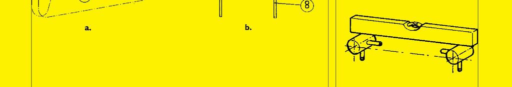
6 Pressure measurement Our instruments for pressure measurement: VT pressure transmitter... Spec. BPV710 VB pressure transmitter... Spec. BPLV770 Process connections Some typical connections for tapping the pressure are shown below. Fig. 1a is for liquids and gases, fi g. 1b for steam, and fi g. 1c for high-pressure service. Suggested material for the branch shown in fi g. 1c is e.g. St35.8 or 13CrMo44. All burrs should be carefully removed from the tapping point. The processor coupling must be welded with a thin compound rod (max. diameter Ø 2.0 mm) to avoid harmful thermal strains, Fig. 1d. Connection pipe Recommended materials for the connection pipe: - AISI304 stainless steel - AISI316 acid-resistant steel For high pressure measurements (above 100 bar): - St35.8 or 13CrMo44 heat-resistant steels 6 Recommended pipe dimensions (o.d. x wall thickness): - Ø 12 1 mm, Ø mm, or Ø mm. It is recommendable always to equip the connection pipe with shut-off valves and, when necessary, with a pressure gauge connection valve. For low pressures and for fl uids liable to form sediments a ball valve should be used as shut-off valve. A threaded or welded needle valve is used for steam and high pressures. Protection from pulsation If pulsations caused by the process occur at the point of measurement, the instrument should be protected by means of a restriction, damping pot, or equivalent means. See fi gure 2 for connection pipe confi guration. After the shut-off valve there is a bend for protective liquid or gas. A ALSO SUITABLE FOR PRESSURE MEASUREMENT VG pressure transmitter... Spec. BPLV700 VL pressure transmitter... Spec. BLV820 SEE ALSO: HPS hydraulic pressure seal... Spec. BP415 Figure 2 1/01 December 31, 2014 loop (12) is installed below the transmitter for collecting condensates. Figure 2 gives an example of the measurement pipe arrangement for a pressure transmitter. Figure 3 illustrates some applications of a pressure transmitter. Pressure Adjustability trans- Span Measuring range mitters min. max. VT3 1.4 kpa (14 mbar) 35 kpa (350 mbar) kpa ( mbar) VT4 4 kpa (40 mbar) 100 kpa (1000 mbar) kpa ( mbar) VT kpa (265 mbar) 500 kpa (5000 mbar kpa ( mbar) VT MPa (1.45 bar) 3 MPa (30bar) MPa ( bar) VTA MPa (1.45 bar) 3 MPa (30 bar) MPa ( bar), abs. VT7 1 MPa (10 bar) 15 MPa (150 bar) MPa ( bar), abs. VT8 6.7 MPa (67 bar) 100 MPa (1000 bar) MPa ( bar) VB 4 4 kpa (40 mbar) 100 kpa (1000 mbar) kpa ( mbar) VB 5 10 kpa (100 mbar) 500 kpa (5000 mbar) kpa ( mbar) VB MPa (0.3 bar) 3 MPa (30bar) -0, MPa ( bar) 1 Pressure transmitter VT 2 Ø 12 / G½ stud coupling 3 Ø 12-G½ pressure gauge connector 4 Ø 12-G½ stud coupling 5 R1/2 pressure gauge connector 6 Gasket 18.5 x 7 mm 7 G½ ball valve 8 Process connection G½ 9 Pipe 12 mm dia. x 1.5 mm AISI Ø 12 / G½ connector Figure 1 Figure 3 a b c d a. Installation of pressure transmitter VG b. Steam and liquid pressure measurement c. Gas pressure measurement with pressure transmitter VT d. Level measurement using the bubbling method e. Level measurement with pressure transmitter VG f. Level measurement; installation by means of the PASVE mounting valve Satron Instruments Inc., P.O.Box 22, FI Tampere, Finland Tel , Telefax ,

7 SATRON VT Pressure Transmitter SATRON VT pressure transmitter belongs to the series V-transmitters. SATRON VT is used for kpa MPa ranges. It is a 2-wire transmitter with HART standard communication. In pressure measuring applications SATRON VT-transmitters are used for measuring the pressure of clean gases, steam and non-crystallizing liquids.the transmitter's sensor is piezoresistive. The rangeability is 100:1 for types VT6 - VT8. TECHNICAL SPECIFICATIONS 7 BPV710 M2, revision Measuring range and span See Selection Chart. Zero and Span adjustment Zero elevation: Calibrated span is freely selectable on the specifi ed range depending from the desired option. This can be made by using extern control shafts, keyboard (display option), HART 275/375 communicator. Damping Time constant is continuously adjustable 0.01 to 60 s. Temperature limits Ambient: -30 to +80 C Process: Process connections 1 and 2: -30 to +125 C Process connections 3 and 5: -30 to +80 C Shipping and storage: -40 to +80 C. Operating temperature of display: 0 to +50ºC (does not affect operation of the transmitter) Pressure limits Min. and max. process pressure: See the appended tables. Process connections 3 and 5: ±0.10 % of calibrated span (span 1:1-5:1 /max.range). On the measuring ranges 5:1-100:1: ( ) ±[ x max.span calibrated span ]% of calibrated span Diaphragm material AISI304: ±1,5 % of calibrated span (span 1:1-100:1 /max.range). (incl. nonlinearity, hysteresis and repeatability) Long-term stability ±0.1 %/max. span/12 months Temperature effect on compensated temperature ranges C Zero and span shift: ±0.15 % of max. span Mounting position effect (VT3 - VT7) Zero error < 0.32 kpa, which can be calibrated out. VT8: mounting position has no effect Other sensing element materials: AISI316, SIS Filling fluid: Silicone oil or inert oil (VT3 - VT7) Enclosure class IP66 Housing with PLUG connector, housing type codes H and T Housing: AISI316, Seals: Viton and NBR TEST jacks: MS358Sn/PVDF, protected with silicone rubber shield. PLUG connector: PA6-GF30 jacket, Silicone rubber seal, AISI316 retaining screw. Housing with junction box/terminal strip, housing type codes M and N Housing: AISI303/316, Seals: Nitrile and Viton ; Nameplates: Polyester Connection hose between sensing element and housing : Codes L and K : PTFE hose with AISI316 braiding. 1) Parts in contact with process medium Load / Ω Volumetric displacement < 0.5 mm 3 /max. span Output 2-wire (2W), 4-20 ma, user selectable for linear, square root, inverted signal or the transfer function (16 points)specifi ed by the user Vibration effect (IEC : FC): ±0.1 % of measuring range/ 2g/10 to 2000 Hz 4g/10 to 100 Hz Power supply effect < ±0.01 of calibrated span per volt Imax = 20.5mA Imin = 3.7mA Supply voltage and permissible load See the load capacity diagram; 4-20 ma output: VDC. Humidity limits % RH; freezing of condensed water not allowed in reference pressure channels. PERFORMANCE SPECIFICATIONS Tested in accordance with IEC 60770: Reference conditions, specifi ed span, no range elevation, horizontal mounting; AISI316L diaphragm, silicone oil fi ll. Accuracy Process connections 1 and 2: ±0.05 % of calibrated span (span 1:1-5:1 /max.range). Insulation test voltage 500 V rms 50 Hz CONSTRUCTION AND CALIBRATION Materials Diaphragm 1) : AISI316L (EN ), AISI304 (EN ), Duplex (EN ), Hast. C276 (EN ), Tantalum or Titanium Gr2 (EN ). Pressure limits Maximum process pressure, MPa Transmitter type VT3 VT4 VT5 VT6 VT7 VT8 Max. overload pressure Pressure class PN40 PN40 PN40 PN100 PN250 PN1000 Rmax = Supply voltage - 10V Imax Supply voltage for transmitter without intrinsic safety (not ATEX) Minimum process pressure (VT8: no min. pressure limitations) T proc. C Minimum pressure for different fill fluids (kpa, abs.) DC cst Supply voltage / V Imax = 20.5mA using HART -communication Imax = 23mA (when the alarm current 22.5mA is on) Inert oil Satron Instruments Inc., P.O.Box 22, FI Tampere, Finland Tel , Telefax ,
 Electrical connections Housing with PLUG connector, H and T: PLUG connector, connector type DIN 43650 model AF; Pg9 gland for cable; wire cross-section 0.5 to 1.5 mm 2.")
8 SATRON VT Pressure Transmitter 8 BPV Calibration For customer-specifi ed range with 1 s. damping. (If range is not specifi ed, transmitter is calibrated for maximum range.) Electrical connections Housing with PLUG connector, H and T: PLUG connector, connector type DIN model AF; Pg9 gland for cable; wire cross-section 0.5 to 1.5 mm 2. Housing with junction box/terminal strip, M and N: M20x1.5, 1/2-NPT inlet; screw terminals for 0.5 to 2.5 mm 2 wires Special Conditions for Safe Use (X) : The enclosure with plastic window and the plastic DIN43650 connector must not be installed in potentially explosive atmosphere requiring category 1 apparatus. The non-conducting surface of the sensor element may be charged by the fl ow of non-conducting media, so there may be electrostatic hazard with IIC-gases. These units should be marked 2 GD. The equipment shall be installed and connected according to the manufacturers instructions. Weight Transmitter - with housing types H and T : 0,7 kg - with housing type M and N : 1.2 kg Product Certifications European Directive Information Electro Magnetic Compatibility (EMC directive 2004/108/EC) All pressure transmitters Atex Directive (94/9/EC) Satron Instruments Inc. complies with the ATEX Directive. European Pressure Equipment Directive (PED) (97/23/EC) All Pressure Transmitters : - Sound Engineering Practice Transmitters with nominal pressure higher than 200 bar fulfi l the requirements of the Conformity Assessment procedure Module A of the directive. Hazardous Locations Certifications Load / Ω European Certifications ATEX Intrinsic Safety Certifi cation No. : DNV-2007-OSL-ATEX- 1346X II 1 GD T135 C EEx ia II C T4-20 C Tamb 50 C II 2 GD T135 C EEx ia II C T4-20 C Tamb 50 C Input Parameters : Ui = 28 V Ii = 93 ma Pi = W Ci = 5 nf Li = 0.2 mh Rmax = Supply voltage - 10V Imax Supply voltage / V Imax = 20.5mA using HART -communication Imax = 23mA (when the alarm current 22.5mA is Supply voltage for transmitter with certified intrinsic safety (ATEX)
9 SATRON VT Pressure Transmitter Dimensions ( in mm) 165 VT3...VT7, ATEX VT8, ATEX +15 Ø48 9 G½ A DIN BPV Pg 9 std. housing codes H and T Hex 36 VT3... VT7 Hex 27 VT8 165 VT3...VT7, ATEX VT8, ATEX Ø48 M20 x 1,5 std. housing code M 195 VT3...VT7, ATEX VT8, ATEX M20 x 1,5 std. housing code N
10 SATRON VT Pressure Transmitter 10 BPV Dimensions ( in mm) 195 VT3...VT7, ATEX VT8, ATEX +15 G½ A DIN Hex 36 VT3... VT7 Hex 27 VT8 PG9 housing N with plug DIN 43650, code N_ / P , ATEX-transmitter ,5 55 G½A Ø26.8 Process connection G½A, fl ush mounted with o-ring, code 5 PG9 std. housing type H M20x1,5 std housing type M Hex , ATEX-transmitter DIN3852-E-G½ Ø26.8 Process connection DIN3852-E-G½A, fl ush mounted, code 3 70 Hex 27 M20x1,5 std housing type N
11 SATRON VT Pressure Transmitter 11 BPV Dimensions (mm) Clearance for cover removal 100 Housing codes H, T and M 215 Housing code N 245 Atex transmitter code 1, Option K min. R75 60 Pg9 std. housing type H and T M20x1.5 std. housing types M and N Option L min. 290 Remote electronics, connecting cable with protection hose, codes L and K DIN Hex 27 Hex M8 G½ G½A G½ ½ - NPT G½ Ø26,3 Thread DIN G½A Orded code : T Thread ½ - 14 NPT Orded code : T PMC 1" (Ø26,3), for process connection code 5 Orded code : T Hex 27 G½ DIN16288 G¼A Thread DIN G¼A Orded code : T For example the process connection of the fl ush mounted transmitter (DIN3852-E-G½) can be changed using modifi cation adapters. Other adapter sizes, please contact to Satron Instruments Inc. Hex 27 G½ ½ - NPT Thread ½ - 14 NPT, female Orded code : M Modification adapters of the process connection, for types VT3... VT8


12 SATRON VT Pressure Transmitter 12 BPV Wiring Housing with terminal strip, code M Wiring Housing with terminal strip and display, code N Wiring Housing with terminal strip and display with plug connector DIN 43650, code N _/ _P Keyboard : Esc = Press Esc move back towards the top of the main menu. = Use the UP arrow key to move up on the current menu level or to increase the selected parameter value. = Use the DOWN arrow key to move down on the current menu level or to decrease the selected parameter value. Enter = Press ENTER to move to a lower level in a menu or to accept a command or parameter value. Wiring Housing with PLUG connector, codes H and T Housing with display, code N Use of selector switch : RUN = working position PZ = Process value zero D = Damping adjustment S = Span adjustment Z = Zero adjustment DN = Down UP = Up Housing with PLUG connector, code T
13 SATRON VT Pressure Transmitter Selection Chart Adjustability Span, min Span, max Measuring range VT3 1.4 kpa (14 mbar) 35 kpa (350 mbar) kpa ( mbar) VT4 4 kpa (40 mbar) 100 kpa (1000 mbar) kpa ( mbar) VT5 10 kpa (100 mbar) 500 kpa (5000 mbar) kpa ( mbar) VTA5 10 kpa (100 mbar) 500 kpa (5000 mbar) kpa ( mbar), abs. VT MPa (0.3 bar) 3 MPa (30bar) MPa ( bar) VTA MPa (0.3 bar) 3 MPa (30 bar) MPa ( bar), abs. VT MPa (1.5 bar) 15 MPa (150 bar) MPa ( bar), abs. VT8 1 MPa (10 bar) 100 MPa (1000 bar) MPa ( bar) Output S 4-20mA DC/HART -protocol 13 Fill fluid (specify for types VT3 - VT7) S Silicone oil G Inert oil BPV Process connection 1 G ½A DIN (male) 2 ½ - NPT (male) 3 DIN 3852-X-G½A (male), Flush Mounted, not VT3, VT8 5 G½A (male), Flush Mounted, with o-ring, not VT3, VT8 Wetted material Body Diaphragm Code Material Code Material 2 AISI316L (EN ) 2 AISI316L (EN ) (no VT8) 3 Hast. C 276 (EN ) (*) 3 Hast. C276 (EN ) (no VT3, VT8) (*) 6 Titanium Gr2 (EN ) (*) 5 Tantalum (no VT3, VT8) (*) 8 Duplex (EN ) (*) 6 Titanium Gr2 (EN ) (no VT3, VT4) (*) 8 Duplex (EN ) (no VT3, VT8) (*) A AISI304 (EN ) Housing type H Housing with PLUG-connector, DIN43650, no display, inlet PG9 T Housing with PLUG-connector and with manual adjust, DIN43650, no display, inlet PG9, (no ATEX) M Housing with junction box/terminal strip, no display, inlet M20x1,5 N Housing with junction box/terminal strip, with display, inlet M20x1,5 Explosion proof 0 No explosion proof classifi cation 1 Atex Intrinsic Safety, II 1 GD T135 C (**) Process coupling 0 No coupling 1 Threaded coupling G½, DIN Threaded coupling G½, DIN 3852-X-G½ (Flush-Mounted) 3 Threaded coupling G½, for process connection code 5 4 Threaded coupling ½ - NPT, for process connection code 2 Special size of electrical inlet N 1/2 NPT G Pg13.5 P Plug DIN Special features Remote electronics (specify only if housing connected with cable to sensing element) - connecting cable with protection hose L Hose protected with PTFE/AISI316 braiding, straight K Hose protected with PTFE/AISI316 braiding, angle of 90 Length of connection cable between sensing element and housing 2 2 m cable 3 3 m cable etc. (max. 10 meter) Mounting parts for remote electronics for Ø 51 mm tube 0 No mounting parts 1 Mounting parts Documentation Calibration certificate AE English Installation and operating instructions I E English I F Finnish Material certificates O No material certifi cate MC1 Raw material certifi cate without appendices, in accordance with SFS-EN (DIN ) standard MC2 Raw material certifi cate for wetted parts, in accordance with SFS-EN (DIN ) standard MC3 Raw material certifi cate for wetted parts, in accordance with SFS-EN B (DIN B) standard (*) = not for process connection code 3 (**) = Housing H and N : II 2 GD T135 C ATEX transmitter with display are the model without membrane key.
14 SATRON VT Pressure Transmitter 14 BPV Process couplings ØD out Ø G½ B Ød A C 2.5 Ø G½ Ø E Order code : M Process coupling DIN 3852-X-G½ Other sizes, please contact to Satron Instruments Inc. G½ T-coupling DIN 3852-X-G½, sizes DN Ø28 ½ - NPT Ø28 Order code : M Process coupling DIN G½ Coupling Order code: M Process coupling ½ - NPT Ø27 G½ Ø18,3 Ø30 Welding assistant M MS Welding Sequence 2 23,5 Welding the coupling M Order code: M Process coupling G½ (for process connection code 5) We reserve the right for technical modifi cations without prior notice. HART is a registered trademark of HART Communication Foundation. Viton is the registered trademark of DuPont Down Elastomers. Hastelloy is the registered trademark of Haynes International. Tefl on is the registered trademark of E.I. du Pont de Nemours & Co

15 SATRON VB Pressure Transmitter SATRON VB pressure transmitter belongs to the series V transmitters. SATRON VB is user-friendly, through the ball valve mounted transmitter which is used for 0-4 kpa MPa ranges. The transmitter communicates in a 2-wire system. In pressure measuring applications SATRON VB transmitter is used for measuring the pressure of gases, steams and sedimenting, crystallizing and sticking liquids. The transmitter's sensor is piezoresistive. The rangeability of the model VB6 is 100:1. The transmitter communicates digitally using the HART protocol. TECHNICAL SPECIFICATIONS 15 BPLV770 M2, revision Measuring range and span See Selection Chart. Zero and Span adjustment Zero elevation: Calibrated span is freely selectable on the specified range depending from the desired option. This can be made by using a HART 275/375 communicator. Damping - Time constant is continuously adjustable from 0.01 to 60 s. Response time Maximum 100 ms Temperature limits Ambient: -30 to +80 C Process: -30 to +125 C Shipping and storage: -40 to +80 C Operating temperature of display: 0 to +50ºC (does not affect operation of the transmitter) Pressure limits Min. and max. process pressure: See the appended tables. Volumetric displacement < 0.5 mm 3 /max. span Output 2-wire (2W), 4-20 ma, user selectable for linear, square root, inverted signal or the transfer function (16 points) specified by the user. Supply voltage and permissible load See the load capacity diagram; 4-20 ma output: VDC. Humidity limits % RH; freezing of condensed water is not allowed in reference pressure channels. PERFORMANCE SPECIFICATIONS Tested in accordance with IEC 60770: Reference conditions, specified span, no range elevation, horizontal mounting; O-ring seals, AISI316L diaphragm, silicone oil fill. Accuracy ±0.1 % of calibrated span (span 1:1-7.5:1 /max.range). On the measuring ranges 7.5:1-100:1: ±[ x max.span ( calibrated span) ]% of calibrated span (incl. nonlinearity, hysteresis and repeatability) Long-term stability ±0.1 % / max. span / 12 months Temperature effect on compensated temperature ranges C: Zero and span error, types VB5 and VB6: ±0.15 % of max.span. Zero and span error, type VB4: ±0.25 % of max.span Mounting position effect (VB4... VB6) Zero error < 0.15 kpa which can be calibrated out. Vibration effect (IEC : FC): ±0.1 % of measuring range/ 2g/10 to 2000 Hz 4g/10 to 100 Hz Power supply effect < ±0.01 % of calibrated span per volt European Directive Information European Pressure Equipment Directive (PED) (97/23/EY) - Sound Engineering Practice Electro Magnetic Compatibility (EMC directive 2004/108/EC) -All pressure transmitters Insulation test voltage 500 V rms 50 Hz Pressure limits Maximum process pressure, MPa Transmitter type VB4 VB5 VB6 Max. overload. pressure, MPa Pressure class PN40 PN40 PN100 CONSTRUCTION Wetted materials: AISI316L (EN and EN ) Other materials: AISI316L, AISI303 Housing with PLUG connector, housing type code H Housing: AISI303/316 Seals: Viton and NBR TEST jacks: MS358Sn/PVDF, protected with silicone rubber shield. PLUG connector: PA6-GF30 jacket, Silicone rubber seal, AISI316 retaining screw. Housing with junction box/terminal strip, housing type codes M and N Housing: AISI303/316; Seals: Nitrile and Viton ; Nameplates: Polyester Filling fluid: Silicone oil or inert oil Enclosure class IP66 Load / Ω R max = Supply voltage - 10V I max Minimum process pressure Minimimum pressure for T different fill fluid (kpa, abs.) proc. DC200 Inert C 100 cst oil I max = 20.5mA Operating region Supply voltage / V I max = 20.5mA using HART -communication I max = 23mA (when the alarm current 22.5mA is on) I min = 3.7mA 40 Satron Instruments Inc., P.O.Box 22, FI Tampere, Finland Tel , Telefax ,
16 SATRON VB Pressure Transmitter Calibration Transmitter is calibrated for maximum range with 1 sec. damping Calibration for customer-specified range and item positioning must be mentioned in the order. 16 Load / Ω BPLV Electrical connections Housing with PLUG connector, code H PLUG connector, connector type DIN model AF; Pg9 gland for cable; wire cross section 0,5...1,5 mm 2. Housing with junction box/terminal strip, code M M16x1.5 inlet; screw terminals for 0,5...2,5 mm 2 wires Product Certifications European Directive Information Electro Magnetic Compatibility (EMC directive 2004/108/EC) All pressure transmitters Atex Directive (94/9/EC) Satron Instruments Inc. complies with the ATEX Directive. European Pressure Equipment Directive (PED) (97/ 23/EC) All Pressure Transmitters : - Sound Engineering Practice Hazardous Locations Certifications Min. load using HART - communication 250 Ω R max = Supply voltage - 12 V Operating region I max I max = 20.5 ma using HART -communication Supply voltage /V I max = 23 ma (when the alarm current 22,5 ma is on) Supply voltage for transmitter with certified intrinsic safety (ATEX) Weight Transmitter - with housing type H: 0.9 kg - with housing type M: 1.4 kg - with housing type N: 1.5 kg 40 European Certifications ATEX Intrinsic Safety Certification No. : DNV-2007-OSL-ATEX- 1346X II 1 GD T135 C EEx ia II C T4-20 C Tamb 50 C II 2 GD T135 C EEx ia II C T4-20 C Tamb 50 C Input Parameters : U i = 28 V I i = 93 ma P i = W C i = 5 nf Li = 0.2 mh Special Conditions for Safe Use (X) : The enclosure with plastic window and the plastic DIN43650 connector must not be installed in potentially explosive atmosphere requiring category 1 apparatus. The non-conducting surface of the sensor element may be charged by the flow of non-conducting media, so there may be electrostatic hazard with IIC-gases. These units should be marked 2 GD. The equipment shall be installed and connected according to the manufacturers instructions. Keyboard : Esc = Press Esc to move back towards the top of the main menu. = Use the UP arrow key to move up on the current menu level or to increase the selected parameter value. = Use the DOWN arrow key to move down on the current menu level or to decrease the selected parameter value. Enter = Press Enter to move to a lower level in a menu or to accept a command or parameter value. Housing with display, code N
17 SATRON VB Pressure Transmitter 17 BPLV Dimensions (mm) A B C Ø48 D E PG9 std. housing type H Hex 41 Hex 36 Process connection code 1 Dim. A Dim. B Dim. C Dim. D Thread E Ø24.5 G1A 75 Ø48 Housing with junction box/terminal strip, code M M20 x 1,5 std. housing type M Housing with junction box/terminal strip, with display, code N 70 M20 x 1,5 std. housing type N

18 USB Rx Tx +5V Ext. p ower in V DC or AC IP40 USB 28 ma L 150R NOTE! Do not switch Vsup ON in live circuit Vsup+ Rx HART R Tx Vsup- HA RT Pwr OK + 24V - Um- 4mA = 0.4V 100R 20mA = 2VDC 0.01% Um+ Um+ Um- Vsup ON/OFF SATRON VB Pressure Transmitter 18 BPLV Housing with junction box/terminal strip, with display and plugconnector DIN 43650, code N--- /-P 90 PG9 std. housing type N with plug DIN Esc Enter ma ma ma Hart Test Test + - Test Load Power Wiring Housing with PLUG connector, code H Load Power Wiring Housing with terminal strip, code M Load Power Wiring Housing with terminal strip, code N Satron SI-Toole Order code : M Si-Toole R USB / HART modem I Load Power Wiring housing N with plug DIN 43650, code N- / P Connection with Satron SI-Toole USB-HART modem
19 SATRON VB Pressure Transmitter Selection Chart Adjustability Span, min Span, max Measuring range 19 BPLV VB 4 4 kpa (40 mbar) 100 kpa (1000 mbar) kpa ( mbar) VB 5 10 kpa (100 mbar) 500 kpa (5000 mbar) kpa ( mbar) VB MPa (0.3 bar) 3 MPa (30bar) MPa ( bar) Output S 4-20mA DC/HART Process connection 1 Thread G1A, extension diameter Ø24.5 mm, extension length 109 mm Wetted materials Body Diaphragm Code Material Code Material 2 AISI316L (EN ) 2 AISI316L (EN ) Fill fluid S Silicone oil G Inert oil (*) Housing type H Housing with PLUG-connector, DIN43650, no display, inlet PG9 M Housing with junction box/terminal strip, no display, inlet M20x1,5 N Housing with junction box/terminal strip, with display, inlet M20x1,5 Explosion proof 0 No explosion proof classification 1 Atex Intrinsic Safety, II 1 GD T135 C (**) Special size of electrical inlet N 1/2 NPT G Pg13,5 P PLUG connector, DIN43650 Documentation Calibration certificate AE English Installation and operating instructions I E English I F Finnish Material certificates O No material certificate MC1 Raw material certificate without appendices, in accordance with SFS-EN (DIN ) standard MC2 Raw material certificate for wetted parts with appendices, in accordance with SFS-EN (DIN ) standard MC3 Raw material certificate for wetted parts with appendices, in accordance with SFS-EN B (DIN B) standard (*) = Oxygen cleaning must be mentioned in the order (**) = Housing H and N : II 2 GD T135 C ATEX transmitters with display are the model without membrane key.
20 20
-0+/12)3 02213140/ 31-31$1-31$14 / \"\"\"\" '\"+/5, &&'&( &&!\"#! $%\"\"\" %&!!\"!\"!\" # '! \"!\" \"!#! ( #\" # \"$#\")#\" ##)*!")
'(+$ *.)*$ ',*.)'*$ 2%6 '\"#)$ *+, '\"#)$ *+,! '%$ *+- $. $+, /0 $+, 1#$2\" 30 # )!\"#$%$\"&!\"#$%$\"'''")
21 )& * """"""""""""" '"+, - %.& &""" '"+ -, 21 7,6,!,6, /)-0+/12) / 31-31$1-31$14 / """" '"+/5, &&'&( &&!"#! $%""" %&!!"!"!" # '! "!" "!#! ( #" # "$#")#" ##)*! #")# # " 4!!! "# $ % &!!$ # "!$ $ $ $ & #$ $!"!#" $%% -!"!#" $%% '(")'($ *+")*+$ *+,*+")*+*+$ (")($ '")'$ ','")''$ -+")-+$ +")+$ ',+")'+$ '(+.)'(+$ *.)*$ ',*.)'*$ 2%6 '"#)$ *+, '"#)$ *+,! '%$ *+- $. $+, /0 $+, 1#$2" 30 # )!"#$%$"&!"#$%$"'''
22 22

23 SATRON VDt Differential Pressure Transmitter SATRON VDt differential pressure transmitter belongs to V-transmitter family. The series V transmitters have both analog and smart properties. SATRON VDt is used for 0-0,1kPa MPa ranges. It is a 2-wire transmitter with HART standard communication. In pressure measuring applications SATRON VDt transmitters are used for measuring differential pressure and absolute pressure. SATRON VDt transmitter is equipped with an SOS (Silicon On Sapphire) or piezoresistive sensing element. The rangeability is 25:1. TECHNICAL SPECIFICATIONS 23 BPdT750 M3, revision Measuring range and span See Selection Chart. Zero and Span adjustment Zero elevation: Calibrated span is freely selectable on the specified range depending from the desired option. This can be made by using extern control shafts (analog option), keyboard (display option), HART 275/375 communicator. Damping Time constant is continuously adjustable 0,01 to 60 s. Temperature limits Sensing element operating: -30 to +125 C Electronics operating: -30 to +80 C Shipping and storage: -50 to +80 C. Operating temperature of display: 0 to +50ºC (does not affect operation of the transmitter) Pressure limits Min. and max. process pressure: Type VDt2 VDt3 VDt4,5 VDt6 VDt3,4,5,7 VDt6 Max. overload pressure, MPa Transmitter operates within specifications for pressures above 10 mbar abs. Process chamber volume (cm 3 ) Pressure class PN40 PN100 PN100 PN100 PN420 PN420 Type Volume (cm 3 ) Standard with hydraulic transmitter seal VDt Volume of negative-side process chamber: < 1 cm 3. Output 2-wire (2W), 4-20 ma, user selectable for linear, square root, inverted signal or the transfer function (16 points)specified by the user Supply voltage and permissible load See the load capacity diagram; 4-20 ma output: VDC. Humidity limits % RH 1) Parts in contact with process medium. PERFORMANCE SPECIFICATIONS Tested in accordance with IEC 60770: Reference conditions, specified span, no range elevation, horizontal mounting; AISI316L-diaphragm, silicone oil fill. Accuracy ±0.05 % of calibrated span (span 1:1-5:1 /max.range). On the measuring ranges 5:1-60:1: ±[ x max.span ( ) ]% of calibrated span calibrated span Special accurate diaphragm AISI304: ±1.5 % of calibrated span (For spans 1:1-60:1) (incl. nonlinearity, hysteresis and repeatability) Long-term stability ±0.1 % of max. span / year Temperature effect on compensated temperature ranges -20 to 80 C Zero and span shift: ±0,15 % of max. span Static pressure effect on Zero of max. span VDt2: ±0,2 % / 4 MPa VDt3...5, PN100: ±0,2 % / 10 MPa VDt6...7, PN100 / PN400: ±0.3 % / 10 MPa Overpressure effect on Zero of max. span VDt2: ±0,5 % / 4 MPa; VDt3...7: PN100: ±0,3 % / 10 MPa; PN400: ±1 % / 40 MPa. Mounting position effect Zero error ± 0.4 kpa, which can be calibrated out. Vibration effect (IEC ): ±0.1 % of measuring range Power supply effect < ±0.01 % of calibrated span / volt. Insulation test voltage 500 V rms 50 Hz CONSTRUCTION AND CALIBRATION Materials Diaphragms 1) : AISI316L (EN ), AISI304 (EN ), Duplex (EN ), Hast. C276 (EN ) or Tantalum. Flanges 1) and vent valves 1) : AISI316, Duplex or Hast. C276. O-ring on sensing element: PTFE. Other sensing element materials: AISI316, SIS 2343, SIS Mounting bolts and nuts for sensor flanges: AISI316 (PN400: m.8.8.zne) Fill fluid Silicone oil (DC200, 10 cst) or inert oil. Housing with PLUG connector, H and T Housing: AISI316 Seals: Viton and NBR TEST jacks: MS358Sn/PVDF, protected with silicone rubber shield. PLUG connector: PA6-GF30 jacket, Silicone rubber seal, AISI316 retaining screw. Housing with junction box/terminal strip, M and N Housing: AISI303/316; Seals: Nitrile and Viton ; Nameplates: Polyester Connection cable between sensing element and housing Codes L and K : PTFE hose with AISI316 braiding. Enclosure class: IP66. Process connections See Selection Table. Calibration For customer-specified range with 1 s. damping. Min. factory calibration range: 10mbar (VDt2). (If range is not specified, transmitter is calibrated for maximum range.) Load / Ω Operating region Supply voltage /V Min. load using HART - communication 250 Ω R max = Supply voltage - 12 V I max I max = 20.5 ma using HART -communication I max = 23 ma (when the alarm current 22,5 ma is on) 40 Satron Instruments Inc., P.O.Box 22, FIN Tampere, Finland Tel , Telefax ,
24 SATRON VDt Differential Pressure Transmitter Electrical connections Housing with PLUG connector, H and T: PLUG connector, connector type DIN model AF; Pg9 gland for cable; wire cross-section 0.5 to 1.5 mm Load / Ω BPdT Housing with junction box/terminal strip, M and N : M20x1.5, 1/2-NPT inlet; screw terminals for 0.5 to 2.5 mm 2 wires Product Certifications European Directive Information Electro Magnetic Compatibility (EMC directive 2004/108/EC) All differential pressure transmitters Atex Directive (94/9/EC) Satron Instruments Inc. complies with the ATEX Directive. European Pressure Equipment Directive (PED) (97/ 23/EC) All Differential Pressure Transmitters : - Sound Engineering Practice Hazardous Locations Certifications European Certifications ATEX Intrinsic Safety Min. load using HART - communication 250 Ω R max = Supply voltage - 12 V Operating region I max I max = 20.5 ma using HART -communication Supply voltage /V I max = 23 ma (when the alarm current 22,5 ma is on) Supply voltage for transmitter with certified intrinsic safety (ATEX) 40 Certification No. : DNV-2007-OSL-ATEX- 1346X II 1 GD T135 C EEx ia II C T4-20 C Tamb 50 C II 2 GD T135 C EEx ia II C T4-20 C Tamb 50 C Input Parameters : U i = 28 V I i = 93 ma P i = W C i = 5 nf Li = 0.2 mh Special Conditions for Safe Use (X) : The enclosure with plastic window and the plastic DIN43650 connector must not be installed in potentially explosive atmosphere requiring category 1 apparatus. The non-conducting surface of the sensor element may be charged by the flow of non-conducting media, so there may be electrostatic hazard with IIC-gases. These units should be marked 2 GD. The equipment shall be installed and connected according to the manufacturers instructions. Weight (kg) Type Housing type H M N VDt ,0 4,6 4,6
25 SATRON VDt Differential Pressure Transmitter Dimensions (in mm) 25 BPdT Pg9 std. housing types H and T Ø Housing types H, T and M 188 Atex transmitter, code 1, 15 mm 41,3±0,2 100 Clearace for Cover Removal 1/4-18 NPSF A - A ±0,2 96 A A M10 / deep 14 M12 / deep 14 7/16-20 UNF / deep 14 M20 x 1,5 std. housing type M M20 x 1,5 std. housing type N 75 Ø48 70 Housing types M 188 Atex transmitter, code 1, 15 mm Housing types N 218 Atex transmitter, code 1, 15 mm Esc Enter
26 SATRON VDt Differential Pressure Transmitter 26 BPdT Dimensions (in mm) Pg9 std. housing type N with DIN plug connector Housing types H, T and M 215 Housing type N 245 Atex transmitter, code 1, +15 mm Housing type N with DIN plug connector 218 Atex transmitter, code 1, 15 mm Esc Enter < min. R75 60 Pg9 std. housing types H and T M20x1,5 std. Housing types M and N Remote electronics, connecting cable with protection hose, codes L and K <450
27 SATRON VDt Differential Pressure Transmitter 27 BPdT Housing with PLUG connector, code T Use of selector switch : RUN = working position PZ = Process value zero D = Damping adjustment S = Span adjustment Z = Zero adjustment DN = Down UP = Up Hart Z RUN 1 S 3 PZ 1.5 D DN UP 3 60 Test 2 ma ma ma Hart S PZ 1 Z.5 3 RUN D DN UP 60 Test Test + - Test Load Power Wiring Housing with PLUG connector, codes H and T Load Power Wiring Housing with terminal strip, code M Wiring Housing with display, code N Load Power Housing with display, code N Load Power Wiring housing with plug DIN 43650, code N-/ P Keyboard : Esc = Press Esc move back towards the top of the main menu. = Use the UP arrow key to move up on the current menu level or to increase the selected parameter value. = Use the DOWN arrow key to move down on the current menu level or to decrease the selected parameter value. Enter = Press ENTER to move to a lower level in a menu or to accept a command or parameter value.
28 SATRON VDt Differential Pressure Transmitter Selection Chart Fill fluid S Silicone oil G Inert oil BPdT VDt Differential Pressure Transmitter VAt Absolute Pressure Transmitter (ranges 4 to 7, range 0...xx, abs.) Adjustability ( ±) Span, min. Span, max. Measurig range 2 0,1 kpa (1 mbar) 6 kpa (60 mbar) kpa ( mbar ) 3 1,4 kpa (14 mbar) 35 kpa (350 mbar) -35 kpa kpa ( mbar) 4 4 kpa (40 mbar) 100 kpa (1000 mba) kpa ( mbar) 5 26,5 kpa (265 mbar) 500 kpa (5000 mbar) kpa ( mbar) 6 0,145 MPa (1,45 bar) 3 MPa (30 bar) MPa ( bar) 7 1 MPa (10 bar) 15 MPa (150 bar ) MPa ( bar) Output S 4-20mA DC/HART -protocol Process connection D M10,PN40 range 2/PN100 ranges 3...6, IEC A M10, PN420 ranges 3, 4, 5 and 7, IEC H M12, PN420 ranges 3, 4, 5 and 7, IEC U 7/16-20 UNF, (PN420 ranges 3, 4, 5 and 7) 28 F Screwed flange adapters, PN40 range 2 and PN420 ranges 3 to 7, IEC V Connection through hydraulic seal Z Welded flange adapters, PN420 ranges 3 to 5 and 7, IEC Wetted Flanges Diaphragm Diaphragm coating material Code Material Code Material Code Material 2 AISI316L (EN ) 2 AISI316L (EN ) (specify only when 3 Hast.C 276 (EN ) 3 Hast.C 276 (EN )(**) coated) 5 Tantalum (**) 9 gold / rhodium 8 Duplex (EN ) (**) A AISI304 (EN ) (**) Housing type H Housing with PLUG-connector, DIN43650, no display, inlet PG9 T Housing with PLUG-connector, DIN43650, no display, inlet PG9, with manual adjust M Housing with junction box/terminal strip, no display, inlet M20x1,5 N Housing with junction box/terminal strip, with display, inlet M20x1,5 Explosion proof 0 No explosion proof classification 1 Atex Intrinsic Safety, II 1 GD T135 C (*) Process thread Thread type Thread size on flange adapter Code Type Code Size (only specify for type F) R straight R thread 2 1/4 N NPS thread 3 3/8 P taper R thread 4 1/2 T NPT thread Special size of electrical inlet N 1/2 NPT G Pg13.5 P Plug DIN Special features Special electronics (specify only if housing connected with hose to sensing element) - connecting cable with protection hose L Hose protected with PTFE/AISI316 braiding, straight K Hose protected with PTFE/AISI316 braiding, angle of 90º Length of cable between sensing element and housing (specify only if housing connected with cable to sensing element) 2 2 m cable 3 3 m cable etc. (max. 20 m) Mounting parts for remote electronics for Ø51 mm tube 0 No mounting parts 1 Mounting parts Documentation Calibration Certificate AE English Installation and Operating Instructions IE English IF Finnish Material Certificates 0 No material certificate MC1 Raw materials certificate without appendixes, in accordance with SFS-EN (DIN ) standard MC2 Raw materials certificate for wetted parts with appendixes, in accordance with SFS-EN (DIN ) standard MC3 Raw materials certificate for wetted parts with appendixes, in accordance with SFS-EN B (DIN B) standard We reserve the right for technical modifications without prior notice. HART is a registered trademark of HART Communication Foundation. Viton is the registered trademark of DuPont Down Elastomers. Hastelloy is the registered trademark of Haynes International. Teflon is the registered trademark of E.I. du Pont de Nemours & Co (*) = Housing H and N : II 2 GD T135 C ATEX transmitters with display are the model without membrane key. (**) = Not for ranges 2-3
29 29
. It is a 2-wire transmitter with HART standard communication.")
30 SATRON VDU SATRON VDU differential pressure transmitter belongs to V-series transmitters. SATRON VDU differential pressure transmitter is used from 0-4 kpa to 0-3 MPa ranges (static pressure + measuring range). It is a 2-wire transmitter with HART standard communication. In pressure measuring applications SATRON VDU diff.pressure transmitters are used for measuring the pressure of clean, sedimenting, crystallizing and sticking materials.the transmitter's sensor is piezoresistive. The rangeability is 25:1. TECHNICAL SPECIFICATIONS Measuring range and span See Selection Chart. Zero and Span adjustment Zero elevation: Calibrated span is freely selectable on the specified range. This can be made by using keyboard or HART 275 communicator. Damping - Time constant is continuously adjustable 0,01 to 60 s. Temperature limits Ambient: -30 to +80 C Process: -30 to +125 C 0 to +200 C (temp. code H) Shipping and storage: -40 to +80 C. Operating temperature of display: 0 to +50ºC (does not affect operation of the transmitter) Pressure limits Min. and max. process pressure: See the appended tables. Volumetric displacement < 0.5 mm 3 /max. span (in both sensors) Output 2-wire (2W), 4-20 ma, user selectable for linear, square root, inverted signal or the transfer function (16 points)specified by the user Supply voltage and permissible load See the load capacity diagram; 4-20 ma output: VDC. Humidity limits % RH; freezing of condensed water not allowed in reference pressure channels. PERFORMANCE SPECIFICATIONS Tested in accordance with IEC 60770: Reference conditions, specified span, no range elevation, horizontal mounting; AISI316L diaphragm, silicone oil fill. Accuracy ±0.2 % of calibrated span (span 1:1-7.5:1 /max.range). On the measuring ranges 7.5:1-25:1: max.span ±[ x ( calibrated span )]% of calibrated span Special accuracy types BA and DA : (Temperature effect on +20 to +70 C) ±0,15 % of calibrated span, only process connections BA and DA / temperature effect code S, for spans 1:1-7,5:1). 1) Parts in contact with process medium Differential Pressure Transmitter using two separate pressure sensors On the measuring ranges 7,5:1-25:1: max.span ±[ x ( )]% of calibrated span calibrated span (incl. nonlinearity, hysteresis and repeatability) Long-term stability ±0.2 % / max. span / year Temperature effect - on -20 to +80 C range Zero and span error: ±0.3 % of max. span. - on 0 C to +200 C range (process temperature code H) ±2 % of max. span, VDU6 ±4 % of max. span, VDU4, VDU5 Temperature effect - on +20 C to +70 C, process connections BA and DA Zero and span error: ±0.15 % of max.span, code S Mounting position effect Zero error < 0.32 kpa, which can be calibrated out. Vibration effect (IEC : FC): ±0.1 % of measuring range/ 2g/10 to 2000 Hz 4g/10 to 100 Hz Power supply effect < ±0.01 of calibrated span per volt Insulation test voltage 500 V rms 50 Hz CONSTRUCTION AND CALIBRATION Materials Diaphragm 1) : AISI316L (EN ), Duplex (EN ), Hast. C276 (EN ), CoNi-alloy, Titanium Gr2 (EN ), Nickel or Tantalum. Coupling 1) : AISI316L (EN ), Duplex (EN ), Hast.C276 (EN ) or Titanium (EN ) Other sensing element materials: AISI316, AISI303. Pressure limits Transmitter type VDU4 VDU4/5 VDU5 VDU5/6 VDU6 Max. overload pressure, MPa Max. operating range (=static pressure +meas. range), kpa Pressure class PN40 PN40 PN40 PN40 PN100 Filling fluid: Silicone oil, food industry oil or inert oil Enclosure class IP66 BPDUV760 M2, revision Electronics housing: AISI303/316, Seals: nitrile rubber and Viton, Nameplates: Polyester Calibration For customer-specified range with 1 s. damping. (If range is not specified, transmitter is calibrated for maximum range.) Process connections See Selection Chart Process couplings: See Selection Chart and installation instructions or technical specification: Couplings for Transmitters G150. Load / Ω Satron Instruments Inc., P.O.Box 22, FIN Tampere, Finland Tel , Telefax , Operating region Supply voltage /V Min. load using HART - communication 250 Ω R max = Supply voltage - 12 V I max I max = 20.5 ma using HART -communication I max = 23 ma (when the alarm current 22,5 ma is on) Min. process pressure Minimum pressure for different fill fluids (kpa, abs) T proc. DC200 Inert oil C 100 cst
31 91 Ø48 SATRON VDU Electrical connections M20x1.5, 1/2-NPT ; screw terminals for 0.5 to 2.5 mm 2 wires and with PLUG connector, connector type DIN model AF; Pg9 gland for cable; wire gross-section 0.5 to 1.5 mm 2. Product Certifications European Directive Information Dimensions (mm) 31 Differential Pressure Transmitter using two separate pressure sensors Electro Magnetic Compatibility (EMC directive 2004/108/EC) All differential pressure transmitters European Pressure Equipment Directive (PED) (97/23/EC) All Differential Pressure Transmitters : - Sound Engineering Practice 230 Weight Mounting type DN50 Flange DN80 SA (Sandvik) Tx (Tri-Clamp) PA (PMC 1") BA, VA, WA UA, VB, WB G1...G4 BPDUV Weight / kg Extension code Standard M20x1.5 M12 or PG9 Sensor 1, master Options of the connecting cable: a) M12 connector are situated at the end of sensor 1 and the end of sensor 2. The material of the cable is PUR. b) Cable is firmly connected to both sensors. The material of the cable is PVC. Cable glands are AISI316. Connecting cable, standard 10 m Max. 20 m 150 M12 or PG9 Sensor 2, slave Dimensions (mm) Double current output Standard PG9 Plug DIN electrical inlets Standard PG9
 32 Differential Pressure Transmitter using two separate pressure sensors Double current output with plug DIN43650 connector")
32 USB Rx Tx +5V Ext. power in V DC or AC IP40 USB HART Pw r OK Um+ + 24V R 0.01% 150R NOTE! Do no t switch Vsup ON in live circuit 90 R 28mA L Vsup+ Um+ Vsup- Um- 4mA = 0.4V 20 ma = 2V D C Um- Rx R Tx Vsup ON/OFF SATRON VDU Dimensions (mm) 32 Differential Pressure Transmitter using two separate pressure sensors Double current output with plug DIN43650 connector BPDUV Standard PG9 Esc Enter ma Test Wiring one current output Load Power Load Power Wiring one current output, plug DIN43650 connector Si-Toole US B / HART modem HART Load Power I ma Test Load Load Power + - Power Load Power Wiring double current output Wiring double current output, plug DIN connector
33 SATRON VDU Differential Pressure Transmitter using two separate pressure sensors Dimensional drawings (dimensions in mm) d 2 33 Sensor 1 (master) 275 Sensor 2 (slave) 190 BPDUV k D Process connections Ax, Dx and Jx, flanged Ø68 Ø84 Ø115 Ø Ø85 Ø115 Ød 4 Sensor 1 : standard M20x1.5 Sensor 1 (master) 225 Sensor 2 (slave) 145 b 19 Process connection UA, - Tuchenhagen DN50/40 (Varivent ) +0.1 Es -0.3 Process connection SA, - Sandvik-clamp 4xØ adjustment ±3 Process connection DA, DN25 PN40 flange with extension, process temperature max C Code E ±0.4 E d Process connections Ax, Dx and Jx, - flange with extension Es , FLANGE SIZE ISO DN25 PN40 ISO DN50 PN40 ISO DN80 PN40 ISO DN100 PN40 ANSI 1" 150 lbs ANSI 1" 300 lbs ANSI 2" 150 lbs ANSI 2" 300 lbs ANSI 3" 150 lbs ANSI 3" 300 lbs ANSI 4" 150 lbs ANSI 4" 300 lbs JIS 10K-50 JIS 40K-50 JIS 10K-80 JIS 40K-80 JIS 10K-100 JIS 40K-100 Flange dimens. Holes Extens. b D Ød 4 pcs d 2 k Ød
34 SATRON VDU 34 Differential Pressure Transmitter using two separate pressure sensors BPDUV Dimensional drawings (dimensions in mm) Sensor 1 (master) 200 Sensor 2 (slave) 115 Ø26.2 Process connection PA - PMC 1" Sensor 1 (master) 210 Sensor 2 (slave) 125 L Hex Ø41-0,025 M45 x 2 Ø41-0,025 M45x2 Hex 46 Process connection BA - M45x2 Process connection BB - M45x2 20 Process connections TA, TB and TC - Tri-clamp DN ,5 BA - extension code L Ø D DN ØD , A A E ØD Process connection VA and VB - SMS38 and SMS51 ØD Process connection WA and WB - SMS-SI38 and SMS-SI51 Size Dimensions ØD A Thread Rd 60 x 1/6 Rd 70 x 1/6 Size SI38 SI51 ØD Dimensions A E Thread Rd 60 x 1/6 Rd 70 x 1/6
35 SATRON VDU Process couplings, G1 thread Differential Pressure Transmitter using two separate pressure sensors Transmitter's process sealing G1 thread Three different options are available for the transmitter's process sealing: BPDUV G1 AISI316L, AISI317L or Duplex diaphragm, o-ring FPM (Viton) (code G5) EHEDG - certified Standard coupling Material: AISI316 L, Titanium or Hastelloy C Special couplings, e.g.: G1 hygienic coupling, M G1/2A/G1 coupling, M G1/2A/G1 coupling with venting, M G1/2A/ G1 couplings with bracket: G1/2A male, M G1/2 female, M SMS-SI couplings : L1 L2 AISI316L, AISI317L or Duplex diaphragm, o-ring EPDM (code G6) EHEDG - certified AISI316L, CoNi-, Duplex, Hastelloy C276 or Tantalum diaphragm, metal/metal taper sealing (diaphragm on sealing face) (code G4) Coupling M45x2 with adjust, for process connection BA, order code M ,5 Ø60 Ød ØD for pipe for vessel Size L Dimensions Ød L2 38, ØD Thread Rd 60 x 1/6 Rd 70 x 1/6 Pasve BA working position: For process connections BA3 and BB 1. Transmitter in measuring 2. Transmitter can be checked, changed, calibrated or the transmitter diaphragm can be flushed Coupling BB M45x2, for process connection BB, order code M (Welding assistant, code M ) M45x2 Ø60
36 SATRON VDU 36 Differential Pressure Transmitter using two separate pressure sensors BPDUV Process temperature/ C 200 PASVE mounting & service valve All PASVE types are also available with pneumatic actuator, flushing and limit switches Recommended application range (horizontal mounting) PASVE GF (NF) (Flange type) L 55 GP (NP) (Welded on pipe) Ø127 ØD Ø70 Ø ambient temperature/ C R A Process temperature limits, code H Keyboard : Esc = Press Esc move back towards the top of the main menu. = Use the UP arrow key to move up on the current menu level or to increase the selected parameter value. = Use the DOWN arrow key to move down on the current menu level or to decrease the selected parameter value. Enter = Press ENTER to move to a lower level in a menu or to accept a command or parameter value. Satron Instruments Inc., P.O.Box 22, FIN Tampere, Finland Tel , Telefax , We reserve the right for technical modifications without prior notice. HART is a registered trademark of HART Communication Foundation. Pasve is a trademark of Satron Instruments Inc. Hastelloy is the registered trademark of Haynes International. Teflon is the registered trademark of E.I. du Pont de Nemours & Co. Viton is the registered trademark of DuPont Down Elastomer. Varivent is a registered trademark of GEA Tuchenhagen.
37 SATRON VDU 37 Differential Pressure Transmitter using two separate pressure sensors Selection Chart Adjustability Span, min Span, max. Measuring range BPDUV VDU4 4kPa (40 mbar) 100 kpa (1000 mbar) kpa ( mbar) VDU4/5 4kPa (40 mbar) 250 kpa (2500 mbar) kpa ( mbar) VDU kpa (265 mbar) 500 kpa (5000 mbar) kpa ( mbar) VDU5/ kpa (265 mbar) 1 MPa (10 bar) MPa ( bar) VDU MPa (1.45 bar ) 3 MPa (30 bar) MPa ( bar ) Output S 4-20mA DC/HART D 4-20mA DC/HART and with galvanic isolation 4-20mA Process connections DA DN25 PN40 ISO AB ANSI 1" 300 lbs ANSI B16-5 UA Tuchenhagen DN50/40 (Varivent ) PN40 DB DN50 PN40 ISO AC ANSI 2" 150 lbs ANSI B16-5 PA PMC 1" PN40 DC DN80 PN40 ISO AD ANSI 2" 300 lbs ANSI B16-5 SA Sandvik DN70 PN64 DD DN100 PN40 ISO AE ANSI 3" 150 lbs ANSI B16-5 BA M45x2 PN160 JA JIS 10K 50 JIS B 2220 AF ANSI 3" 300 lbs ANSI B16-5 BB M45x2 PN160 JB JIS 40K 50 JIS B 2220 AG ANSI 4" 150 lbs ANSI B16-5 G4 G1 thread, metal/metal taper sealing JC JIS 10K 80 JIS B 2220 AH ANSI 4" 300 lbs ANSI B16-5 G5 G1 thread, FPM 0-ring sealing (¹) JD JIS 40K 80 JIS B 2220 TA Tri-clamp DN38 PN40 ISO 2852 G6 G1 thread, EPDM 0-ring sealing (¹) JE JIS 10K 100 JIS B 2220 TB Tri-clamp DN51 PN40 ISO 2852 VA SMS 38 JF JIS 40K 100 JIS B 2220 TC Tri-clamp DN63.5 PN40 ISO 2852 VB SMS 51 AA ANSI 1" 150 lbs ANSI B16-5 WA SMS-SI 38 with extension 24 mm WB SMS-SI 51 with extension 27 mm Extension length (Flanged (Sandvik (mm) conn.) conn.) (not proc.conn. SA) (only proc.conn. DA1, DN25 PN40, max C) (not proc.conn. BB, VA, VB, WA, WB, Tx, UA, PA, DA, G1, G2, G4) (only proc.conn. BA) (not proc.conn. BB, VA, VB, WA, WB, Tx, UA, PA, DA, G1, G2, G4) (not proc.conn. BB, VA, VB, WA, WB, Tx, UA, PA, DA, G1, G2, G4) Wetted materials Extension or other Diaphragm wetted parts Code Material Code Material Code Material 1 Nickel (x) (*) 5 Tantalum (*) 2 AISI316L 2 AISI316L 6 Titanium (xx) 3 Hast.C Hast.C 276 (*) 8 Duplex (*) 8 Duplex Filling oil S Silicone oil G Inert oil A Food industry oil (Neobee M20) Housing type, master N Housing with junction box/terminal strip, display, inlet M20x1,5 Explosion proof 0 No explosion proof classification Diaphragm coating Code Material 9 gold/rhodium Y diamond (specify only when coated) Process N C H C (*) temperature S C (only process connections BA and DA) Cable between sensors 1 PUR cable with M12 connector both end of cable 2 PVC cable with AISI316/ PG9 inlet, fixed factory mounted Process couplings Material 0 Will be ordered separately 2 AISI316L A With coupling 3 Hast.C276 6 Titanium 8 Duplex Special sizes of electrical inlets (Standard M20x1.5) N 1/2 NPT G Pg13.5 P PLUG connector, DIN43650 Documentation Calibration certificate AE English Installation and Operating Instructions I E English I F Finnish Material certificates 0 No material certificate MC1 Raw material certificate without appendixes, in accordance with SFS-EN (DIN ) standard MC2 Raw material certificate for wetted parts, in accordance with SFS-EN (DIN ) standard MC3 Raw material certificate for wetted parts, in accordance with SFS-EN B (DIN B) standard (x) = only with flange (xx) = only with flange and G4 (¹) = EHEDG - certified (*) = not proc.conn. G5 and G6
38 Flow measurement Our instruments for flow measurement: 38 2/02 April 30, 2010 FOR MEASUREMENT IN AN OPEN CHANNEL: - Condensate pot... Spec. G450 - VDt differential pressure transmitter... Spec. BPdT750 VG pressure transmitter... Spec. BPLV700 VV pressure transmitter... Spec. BLV810 FOR MEASUREMENT IN A PIPE: VDt differential pressure transmitter... Spec. BPdT750 Measurement in a pipe by means of restricting element (Fig. 1) The fl ow to be measured in a pipe is passed through a restricting device and the pressure differential between two points, one upstream of the restriction and the other immediately downstream from it, is measured by means of a transmitter. (Pressure upstream of the restriction = the high-pressure or positive side, and the pressure downstream = the lowpressure or negative side). The differential pressure p thus obtained is proportional to the square of fl ow Q, i.e., Q = k p (k = constant) For this reason a linearization relay is normally required in a control loop between transmitter and controller. It is also possible to use a transmitter that incorporates square root extraction. Open channel measurement (Fig. 2) Open channel measurement is used primarily for liquids that contain impurities (e.g. waste water). Measurement is based on restricting the fl ow in such a manner that the level rises upstream of the restriction. Level variations are measured with either a bubbling tube or a fl anged transmitter (see Liquid level measurement). The signal thus obtained is linearized as follows: Weir with rectangular opening, and Venturi fl ume: Q = kh 3/2 (k = constant) Weir with V opening: G3/8 Q = kh 5/2 connection plugged DIN910 pipe plug Figure G½A, DIN19207, Form R Figure 2 G½A DIN19207, Form V AV17 89 Figure 1 Satron Instruments Inc., P.O.Box 22, FI Tampere, Finland Tel , Telefax ,
!")


39 39! " & '( # $% )! " + & '( $ * # $% % %

40 Condensate pot Application 40 G In steam fl ow measurement special condensate pots are installed in the immediate vicinity of restricting organ. The connection pipes from the restricting device to the condensate pots are full of steam, and from the condensate pot to the meter full of condensate. The condensate pots must be mounted in such a manner that the liquid levels are the same in them. The function of the condensate pots is to condensate steam into a liquid (e.g. to protect the transmitter from heat, to prevent dribbling), to keep the liquid levels unaltered with overfl ow and to collect air. The condensate water transmits the pressure to the transmitter, so that the transmitter itself is not in contact with steam. Construction Condensing Pots are designed according to DIN Connections with thread according to DIN Form R and V. They fulfi l the requirements of the PED 97/23/EC. Pressure / Temperature curve Technical specification 30 Volume: 0.3 liters Operating pressure, max.: 100 bar (10 MPa) Operating temperature, max.: +450 C Materials - housing: HII DIN (Wnr ) - pipes: St 35.8/II (Wnr ) Surface handling: fresh paint Weight: 1.8 kg Operating pressure / MPa AV17 89 G½A G3 / 8 connection plugged DIN910 pipe plug 25 Operating temperature / C DIN19207, Form V 100 G½A, DIN19207, Form R We reserve the right to make technical changes without prior notice. Satron Instruments Inc., P.O.Box 240, FIN Tampere, Finland Tel , Telefax
41 41
42 Liquid level measurement Our instruments for liquid level measurement: VG pressure transmitter... Spec. BPLV700 VV pressure transmitter... Spec. BLV810 VVFe pressure transmitter... Spec. BLV811 VL pressure transmitter... Spec. BLV820 VDtL differential pressure transmitter. Spec.BLVT /01 December 31, 2014 ALSO SUITABLE FOR LIQUID LEVEL MEASUREMENT VDt differential pressure transmitter... Spec.BPdT750 Liquid level measurement using a transmitter In an open vessel the liquid level is propotional to the hydrostatic pressure in the vessel, and level can be measured by means of pressure measurement. The most commonly used methods are measurement through the side of the vessel by means of a fl anged pressure or differential pressure transmitter, as in fi g. 2 (the negative leg connection of differential pressure transmitter is left open), and bubbling tube measurement, as in fi g. 3. In the latter method compressed air is fed through a monitoring rotameter into a bubbling tube and the back pressure produced in the tube proportional to liquid level is measured. The choice between these two methods, bubbling tube or fl anged transmitter, is determined between by the ease of making the process connection and by the likelihood of sedimentation. The bubbling tube is well suited for applications such as level measurement in a stock chest made of cement where, especially at some later date, it would be diffi cult to install a side connection for a fl anged transmitter. In general a fl anged transmitter is suitable for almost any type of vessel. With fl uids liable to form sediments the measuring diaphragm can be kept clean by washing it trough a special fl ushing fl ange (fi g. 1). The fl ange is installed between the transmitter and the process fl ange. A continious or periodic water fl ow is issued through the fl ushing bore. If level variations are small and if the fl uid is not liable to form sediments, a fl oat type transmitter can be used. In a pressurized vessel the liquid level can be measured with a fl angeless or fl anged differential pressure transmitter (fi g. 4). When measuring fl uids liable to form sediments, a fl anged transmitter is equipped with a fl ushing fl ange when necessary. As in open vessel, a fl oat type transmitter can be used for level measurement if there is no risk of sedimentation and if level variations are small. Calculating the calibration values (fig. 2) To simplify the calculations, the effect of the density of the gas above the liquid level has been ignored. s, h, and k = distances as in fi g. 2. d I = relative density of the liquid with res-pect to water at 4 c. d 2 = relative density with respect to water of the fi ll fl uid in the negative leg. When s, h, and k are expressed in metres, the unit for range elevation, span, and supression is mh 2 O; for millimetres the unit is mmh 2 O, etc. Open vessel Span = d I h Elevation = d I s Range = d I s to (d I s + d I h Example: If d I = 1.2, h = 1000 mm, and s = 500 mm, then span = 1.2 x 1000 mmh 2 O = 1200 mmh 2 O, elevation = 1.2 x 500 mmh 2 O = 600 mmh 2 O, range = 600 to ( ) = 600 to 1800 mmh 2 O 59 to 177 mbar. Pressurized vessel When no fi ll fl uid is used in the negative leg, the calculation is the same as for open vessel. If the negative leg is fi lled with condensate or some other liquid, then span = d I h suppression = d I s d 2 k range = (d I s d 2 k) to (d I s d 2 k) + d I h Example: If d I = 0.9, d 2 = 1.0, h = 5m, s = 1 m, and k = 6.5 m, then Span = 0.9x5 mh 2 O = 4.5 mh 2 O, Suppression = (0.9x1-1.0x6.5) mh 2 O = -5.6 mh 2 O Range = -5.6 to ( ) mh 2 O = -5.6 to -1.1 mh 2 O = -549 to -108 mbar. The minus sign indicates that, when calibrating, the pressure is taken to the negative side of the transmitter. OPEN VESSEL PRESSURIZED VESSEL Figure 1 1 Pressure transmitter VL 2 M 16 nut 3 DN80 gaskets 4 Process fl ange 5 Flushing fl ange 6 GE8-L1/4 BSP stud coupling Figure 2 Satron Instruments Inc., P.O.Box 22, FI Tampere, Finland Tel , Telefax ,
43 Liquid level measurement Installation examples As regards process connection materials and connection piping, the requirements are the same as in pressure measure-ment. Figure I shows an ordinary fl anged transmitter in an open vessel application, with corresponding process fl ange and fl ushing fl ange. Figure 3 shows an installation example for bubbling tube application. Figure 4 illustrates level measurement in a pressurized vessel with fl anged transmitter. When measuring liquid level in an open vessel in the same manner, the suppression pipe is not needed. Bating of the piping system and vessel have to be taken account when selecting the gasket material. Gasket materials have to be selected in such a way that the eventual bate is not absorbed in the gasket (e.g. Viton ) Stud coupling, Ø12 mm dia./ G½ male 2 Tee, 12 mm dia. 3 Double male connector, Ø12 mm dia. 4 Plug 5 Ball valve 6 Process connection, G½ 7 Pipe, Ø12 x 1 calibred 8 Gasket DN80 9 Flange connection DN80 10 Nut Figure 4 3/02 December 31, 2014 Liquid Adjustability level Span Measuring range measurement min. max. VG3 1.4 kpa (14 mbar) 35 kpa (350 mbar) kpa ( mbar) VG4 4kPa (40 mbar) 100 kpa (1000 mbar) kpa ( mbar) VG5 10 kpa (100 mbar) 500 kpa (5000 mbar) kpa ( mbar) VGA5 10 kpa (100 mbar) 500 kpa (5000 mbar) kpa ( mbar), abs. VG MPa (0,3 bar ) 3 MPa (30 bar) MPa ( bar ) VGA MPa (0,3 bar) 3 MPa (30 bar) MPa ( bar), abs. VG MPa (1,5 bar) 15 MPa (150 bar) MPa ( bar), abs. VG8 1 MPa (10 bar) 25 MPa (250 bar ) MPa ( bar) VVx3 1,4kPa (14 mbar)3 5 kpa (350 mbar) kpa ( mbar) VVx4 x) 4kPa (40 mbar) 100 kpa (1000 mbar) kpa ( mbar) VVx5 10 kpa (100 mbar) 500 kpa (5000 mbar) kpa ( mbar) VVFe 4 4kPa (40 mbar) 100 kpa (1000 mbar) kpa ( mbar) VVFe 5 10kPa (100 mbar) 500 kpa (5000 mbar) kpa ( mbar) VL3 1.4kPa (14 mbar) 35 kpa (350 mbar) kpa ( mbar) VL4 4kPa (40 mbar) 100 kpa (1000 mbar) kpa ( mbar) VL5 10 kpa (100 mbar) 500 kpa (5000 mbar) kpa ( mbar) VLA5 10 kpa (100 mbar) 500 kpa (5000 mbar) kpa ( mbar), abs. VL6 0,03 MPa (0,3 bar) 3 MPa (30 bar) MPa ( bar) VLA6 0,03 MPa (0,3 bar) 3 MPa (30 bar ) MPa ( bar), abs. VL7 1 MPa (10 bar) 15 MPa (150 bar) MPa ( bar), abs. VDtL kpa (14 mbar) 35 kpa (350 mbar) kpa ( mbar) VDtL4 4 kpa (40 mbar) 100 kpa (1000 mbar) kpa ( mbar) VDtL kpa (265 mbar) 500 kpa (5000 mbar) kpa ( mbar) VDtL kpa (1.45 bar) 3 MPa (30 bar) MPa ( bar) 1 Pressure transmitter VG 2 Special fi tting 3 Stud elbow WE8-L/1/4 4 Stud coupling, SF8-L/1/4 5 Rotameter x) See the data sheet BLV810 Figure 3 Viton is the registered trademark of Du Pont Down Elastomers.


44 SATRON VG Flush Mount Pressure Transmitter SATRON VG pressure transmitter belongs to the series V transmitters which will have both analog and smart properties. SATRON VG is used for kpa MPa ranges. It is a 2-wire transmitter with HART standard communication. In pressure measuring applications SATRON VG transmitters are used for measuring the pressure of clean, sedimenting, crystallizing and sticking materials. The transmitter's sensor is piezoresistive. The rangeability is 100:1 for types VG6 - VG7. 44 BPLV700 M2, revision TECHNICAL SPECIFICATIONS Measuring range and span See Selection Chart. Zero and Span adjustment Zero elevation: Calibrated span is freely selectable on the specified range depending from the desired option. This can be made by using extern control shafts, keyboard (display option) or HART 275/375 communicator. Damping - Time constant is continuously adjustable 0.01 to 60 s. Temperature limits Ambient: -30 to +80 C Process: -30 to +125 C 0 to +200 C (temp. code H) Shipping and storage: -40 to +80 C. Operating temperature of display: 0 to +50ºC (does not affect operation of the transmitter) Pressure limits Min. and max. process pressure: See the appended tables. Volumetric displacement < 0.5 mm 3 /max. span Output 2-wire (2W), 4-20 ma, user selectable for linear, square root, inverted signal or the transfer function (16 points)specified by the user Supply voltage and permissible load See the load capacity diagram; 4-20 ma output: VDC. Humidity limits % RH; freezing of condensed water is not allowed in reference pressure channels. PERFORMANCE SPECIFICATIONS Tested in accordance with IEC60770: Reference conditions, specified span, no range elevation, horizontal mounting; O-ring seals, AISI316L diaphragm, silicone oil fill. Accuracy ±0.05 % of calibrated span (span 1:1-5:1 /max.range). On the measuring ranges 5:1-100 :1: ( ) ±[ x max.span ]% of calibrated span calibrated span (incl. nonlinearity, hysteresis and repeatability) Long-term stability ±0.1 % / max. span / 1 year Temperature effect - on -20 to +80 C range (process temperature code N) Zero and span error: ±0.15 % of max. span. - on 0 to +200 C range (process temperature code H) Zero and span error: ±1 % of max. span, VG6 - VG8 ±2 % of max. span, VG4 - VG5 Mounting position effect Zero error < 0.32 kpa, which can be calibrated out. Vibration effect (IEC : FC): ±0.1 % of measuring range/ 2g/10 to 2000 Hz 4g/10 to 100 Hz Power supply effect < ±0.01 of calibrated span per volt Insulation test voltage 500 V rms 50 Hz CONSTRUCTION AND CALIBRATION Materials Diaphragm 1) : AISI316L (EN ), Duplex (EN ), Hast. 276 (EN ), CoNi-alloy, Titanium Gr2 (EN ) or Tantalum. Coupling 1) : AISI316L (EN ), Duplex (EN ), Hast.C276 (EN ) or Titanium Gr2 (EN ). Other sensing element materials: AISI316, SIS Filling fluid: Silicone oil, food industry oil or inert oil Enclosure class IP66 1) Parts in contact with process medium Pressure limits Maximum process pressure, MPa Transmitter type VG3 VG4 VG5 VG6 VG7 VG8 Max. overload pressure Pressure class PN40 PN40 PN40 PN100 PN250 PN250 Housing with PLUG connector, housing type codes H and T Housing: AISI303/316 Seals: Viton and NBR TEST jacks: MS358Sn/PVDF, protected with silicone rubber shield. PLUG connector: PA6-GF30 jacket, Silicone rubber seal, AISI316 retaining screw. Housing with junction box/terminal strip, housing type codes M and N Housing: AISI303/316; Seals: Nitrile and Viton ; Nameplates: Polyester Connection hose between sensing element and housing Codes L and K: PTFE hose with AISI316 braiding. Supply voltage for transmitter without intrinsic safety (not ATEX) Minimum process pressure Minimum pressure for T different fill fluids proc. (kpa, abs.) C DC cst Inert oil Satron Instruments Inc., P.O.Box 22, FI Tampere, Finland Tel , Telefax ,
45 SATRON VG Flush Mount Pressure Transmitter Calibration For customer-specified range with 1 s. damping. (If range is not specified, transmitter is calibrated for maximum range.) Electrical connections Housing with PLUG connector, H and T: PLUG connector, connector type DIN model AF; Pg9 gland for cable; wire cross-section 0.5 to 1.5 mm 2. Housing with junction box/terminal strip, M and N : M20x1.5, 1/2-NPT inlet; screw terminals for 0.5 to 2.5 mm 2 wires 45 BPLV Special Conditions for Safe Use (X) : The enclosure with plastic window and the plastic DIN43650 connector must not be installed in potentially explosive atmosphere requiring category 1 apparatus. The non-conducting surface of the sensor element may be charged by the flow of non-conducting media, so there may be electrostatic hazard with IIC-gases. These units should be marked 2 GD. The equipment shall be installed and connected according to the manufacturers instructions. Process connections G1 connecting thread Process couplings: See Selection Chart and installation instructions or technical specification: Couplings for Transmitters G150. Weight Transmitter - with housing type H and T: 0.7 kg - with housing type M ja N: 1.2 kg Product Certifications European Directive Information Electro Magnetic Compatibility (EMC directive 2004/108/EC) All pressure transmitters Atex Directive (94/9/EC) Satron Instruments Inc. complies with the ATEX Directive. European Pressure Equipment Directive (PED) (97/ 23/EC) All Pressure Transmitters : - Sound Engineering Practice Load / Ω Min. load using HART - communication 250 Ω R max = Supply voltage - 12 V Operating region I max I max = 20.5 ma using HART -communication Supply voltage /V I max = 23 ma (when the alarm current 22,5 ma is on) Supply voltage for transmitter with certified intrinsic safety (ATEX) 40 Hazardous Locations Certifications European Certifications ATEX Intrinsic Safety Certification No. : DNV-2007-OSL-ATEX- 1346X ma II 1 GD T135 C EEx ia II C T4-20 C Tamb 50 C S Z PZ II 2 GD T135 C EEx ia II C T4-20 C Tamb 50 C Hart RUN D DN UP 60 Test Input Parameters : U i = 28 V I i = 93 ma P i = W C i = 5 nf Li = 0.2 mh Load Power + Wiring Housing with PLUG connector, codes H and T
46 SATRON VG Flush Mount Pressure Transmitter Dimensions (in mm) , ATEX +15 Process temperature code H +40 BPLV Ø25 G1A Ø48 Pg 9 std. housing types H and T AV36 195, ATEX +15 Process temperature code H Ø48 M20x1,5 std. housing type M 225, ATEX +15 Process temperature code H M20x1,5 std. housing type N Esc Enter
47 SATRON VG Flush Mount Pressure Transmitter Dimensions (in mm) , ATEX +15 Process temperature code H +40 BPLV Ø25 G1A Pg 9 housing type N with DIN43650 plug-connector Esc Enter Clearance for cover removal 100 Housing types H, T and M 215 Housing type N 245 (Process temperature code H, +40, Atex transmitter, code 1, +15) 125 Option K Hex 36 min. R75 60 Pg9 std. housing types H and T M20x1.5 std. housing types M and N Option L 160 Hex 36 Remote electronics, connecting cable with protection hose, codes L and K min. 300 ma ma Test Test Load Power Wiring Housing with terminal strip, code M Load Power Wiring Housing with terminal strip and display, code N Load Power Wiring Housing with terminal strip and display with DIN plug-connector, code N / P

48 SATRON VG Flush Mount Pressure Transmitter Couplings Transmitter's process sealing Three different options are available for the transmitter's process sealing: BPLV Standard coupling Material: AISI316 L or Hastelloy C Special couplings: G1 hygienic coupling, M G1/2A/G1 coupling, M G1/2A/G1 coupling with venting, M G1/2A/ G1 couplings with bracket: G1/2A male, M G1/2 female, M G1 AISI316L, AISI317L or Duplex diaphragm, FPM (Viton) or EPDM O-ring (code 5 or 6) EHEDG - certified AISI316L, CoNi-, Duplex, Hastelloy C276, Tantalum or Titanium diaphragm, metal/metal taper sealing (diaphragm also on sealing face) (code 4) Flanges: Dimensions of flanged couplings, see the installation and setting-up instructions PASVE mounting & service valve All PASVE types are also available with pneumatic actuator, flushing and limit switches. PASVE GF (NF) (Flange type) GP (NP) (Welded on pipe) GC (NC) (Welded on container) Process temperature limits, code H Process temperature/ C L Recommended application range (horizontal mounting) R262 Ø127 ØD Ø70 Ø A ambient temperature/ C 80 Hart Z RUN S PZ 1.5 D DN UP 3 60 Test Use of selector switch : RUN = working position PZ = Process value zero D = Damping adjustment S = Span adjustment Z = Zero adjustment DN = Down UP = Up Housing with PLUG connector, housing code T Keyboard : Esc = Press Esc move back towards the top of the main menu. = Use the UP arrow key to move up on the current menu level or to increase the selected parameter value. = Use the DOWN arrow key to move down on the current menu level or to decrease the selected parameter value. Enter = Press ENTER to move to a lower level in a menu or to accept a command or parameter value. Housing with display, housing code N
 VG4 4 kpa (40 mbar) 100 kpa (1000 mbar) -100...+100 kpa (-1000...1000 mbar) VG5 10 kpa (100 mbar) 500 kpa (5000 mbar) -100...+500 kpa (-1000.")
49 SATRON VG Flush Mount Pressure Transmitter BPLV Selection Chart Adjustability Span, min Span, max Measuring range VG3 1.4 kpa (14 mbar) 35 kpa (350 mbar) kpa ( mbar) VG4 4 kpa (40 mbar) 100 kpa (1000 mbar) kpa ( mbar) VG5 10 kpa (100 mbar) 500 kpa (5000 mbar) kpa ( mbar) VGA5 10 kpa (100 mbar) 500 kpa (5000 mbar) kpa ( mbar), abs. VG MPa (0.3 bar ) 3 MPa (30 bar) MPa ( bar ) VGA MPa (0.3 bar) 3 MPa (30 bar) MPa ( bar), abs. VG MPa (1.5 bar) 15 MPa (150 bar) MPa ( bar), abs. VG8 1 MPa (10 bar) 25 MPa (250 bar) -0, MPa ( bar) Output S 4-20mA DC/HART -protocol (1) (1) Process seal 4 metal/metal taper 5 O-ring FPM (Viton ) 6 O-ring EPDM Wetted materials Code Material 2 AISI316L (EN ) 3 Hast. C 276 (*) (**) 5 Tantalum (*) (**) 49 Code Material 6 Titanium Gr2 (*) (**) (****) 7 CoNi-alloy (*) (not ranges 3-4) 8 Duplex (EN ) (*) (**) Fill fluid S Silicon oil G Inert oil A Food and beverage special oil (Neobee M20) Diaphragm coating Code Material 9 gold/rhodium Y diamond (specify only when coated) Housing type H Housing with PLUG-connector, DIN43650, no display, inlet PG9 T Housing with PLUG-connector and with manual adjust, DIN43650, no display, inlet PG9, (no ATEX) M Housing with junction box/terminal strip, no display, inlet M20x1,5 N Housing with junction box/terminal strip, with display, inlet M20x1,5 Explosion proof 0 No explosion proof classification 1 Atex Intrinsic Safety, II 1 GD T135 C (***) Process temperature limits N C H C (*) (**) Process coupling Material 0 No coupling E Hygienic coupling 2 AISI316L G Standard 3 Hast.C276 coupling 6 Titanium Gr2 8 Duplex PASVE mounting valve, specify separately in the order Specify special couplings separately in the order Special size of electrical inlet N 1/2 NPT G Pg13.5 P Plug connector DIN Special features Remote electronics (specify only if housing connected with cable to sensing element) - connecting cable with protection hose L Hose protected with PTFE/AISI316 braiding, straight K Hose protected with PTFE/AISI316 braiding, angle of 90 Length of connection cable between sensing element and housing 2 2 m cable 3 3 m cable etc. (max. 10 m) Mounting parts for remote electronics for Ø 51 mm tube 0 No mounting parts 1 Mounting parts Documentation Calibration certificate AE English Installation and operating instructions I E English I F Finnish Material certificates 0 No material certificate MC1 Raw material certificate without appendices, in accordance with SFS-EN (DIN ) standard MC2 Raw material certificate for wetted parts, in accordance with SFS-EN (DIN ) standard MC3 Raw material certificate for wetted parts, in accordance with SFS-EN B (DIN B) standard We reserve the right for technical modifications without prior notice. HART is the registered trademark of HART Communication Foundation. Pasve is the registered trademark of Satron Instruments Inc. Hastelloy is the registered trademark of Haynes International. Teflon is the registered trademark of E.I. du Pont de Nemours & Co. Viton is the registered trademark of DuPont Down Elastomer. (*) = only process seal code 4 (**) = not for range 3 (***) = Housing H and N : II 2 GD T135 C ATEX transmitters with display are the model without membrane key. (****) = Min. process temperature limits 0 C (1) = EHEDG - certified

50 SATRON VV Pressure Transmitter SATRON VV pressure transmitter belongs to V-transmitter family. The series V transmitters have both analog and smart properties. SATRON VV is used for kpa MPa ranges. It is a 2-wire transmitter with HART standard communication. SATRON VV pressure transmitter is suitable for liquid level measurements in ground, rock and ships' tanks, and in open channels. SATRON VV pressure transmitter can be used in corrosive conditions and to measure contaminating liquids. Possible foam on the surface of the measured liquid does not disturb the measurement. SATRON VV does not require compressed air supply. The transmitter's sensor is piezoresistive. The rangeability is 50:1 for type VV5. TECHNICAL SPECIFICATIONS Measuring range and span See Selection Chart. Zero and Span adjustment Zero elevation: Calibrated span is freely selectable on the specified range depending from the desired option. This can be made by using extern control shafts (analog option), keyboard (display option) or HART 275/375 communicator. Damping Time constant is continuously adjustable 0.01 to 60 s. Temperature limits Process: -10 to +125 C Ambient: -30 to +80 C Shipping and storage: -40 to +80 C. Operating temperature of display: 0 to +50ºC (does not affect operation of the transmitter) Equipment cabinet is recommended for extremely demanding conditions. Pressure limits Min. and max. process pressure: See the appended tables. Output 2-wire (2W), 4-20 ma, user selectable for linear, square root, inverted signal or the transfer function (16 points)specified by the user Supply voltage and permissible load See the load capacity diagram; 4-20 ma output: VDC. Humidity limits % RH; freezing of condensed water is not allowed in reference pressure channels. PERFORMANCE SPECIFICATIONS Tested in accordance with IEC 60770: Reference conditions, specified span, no range elevation,aisi316l diaphragm, silicone oil fill. Accuracy ±0.05 % of calibrated span (span 1:1-5:1 /max.range). On the measuring ranges 5:1-50:1: ±[ x max.span ( ) ]% of calibrated span calibrated span (incl. nonlinearity, hysteresis and repeatability) Long-term stability ±0.1 % of max. span per 12 months Temperature effect on compensated temperature ranges Zero and span shift: ±0.15 % of max.span Mounting position effect Zero error <0.32 kpa, which can be calibrated out. Vibration effect (IEC : FC): ±0.1 % of measuring range/ 2 g/10 to 2000 Hz 4 g/10 to 100 Hz Power supply effect <±0.01 % of calibrated span per volt. Insulation test voltage 500 V rms 50 Hz. CONSTRUCTION AND CALIBRATION Materials Diaphragm 1) : AISI316L (EN ), Hast. C276 (EN ) or Tantalum. Sensing element 1) : AISI316, PTFE/ AISI316 or PVC Other materials: SIS2343 Fill fluid Silicone oil or inert oil. Housing with PLUG connector, codes H and T Housing: AISI316/303 Seals: Viton and NBR TEST jacks: MS358Sn/PVDF, protected with silicone rubber shield. PLUG connector: PA6-GF30 jacket, Silicone rubber seal, AISI316 retaining screw. Housing with junction box/terminal strip, codes M and N Housing: AISI303/316; Seals: Nitrile and Viton ; Nameplates: Polyester Connection cable between sensing element and housing (code Land K): PTFE hose with AISI316 braiding. Pressure limits Maximum process pressure, MPa Transmitter type VV...3 VV...4 VV Max. overload pressure Pressure class PN40 PN40 PN40 Load / Ω 1400 Minimum process pressure for different fill fluids (kpa,abs.) DC cst Satron Instruments Inc., P.O.Box 22, FI Tampere, Finland Tel , Telefax , BLV810 M2, revision Equipment cabinet Rittal AE1380, Steel cabinet with polyester paint. Enclosure class: IP66. Calibration For customer-specified range with 1 s. damping. (If range is not specified, transmitter is calibrated for maximum range.) Electrical connections Housing with PLUG connector, codes H and T: PLUG connector, connector type DIN model AF; Pg9 gland for cable; wire cross-section 0.5 to 1.5 mm 2. Housing with junction box/terminal strip, codes M and N: M20x1.5, 1/2-NPT inlet; screw terminals for 0.5 to 2.5 mm 2 wires. 1) Parts in contact with process medium Minimum process pressure T proc. C Operating region Min. load using HART - communication 250 Ω R max = Supply voltage - 12 V I max I max = 20.5 ma using HART -communication Supply voltage /V I max = 23 ma (when the alarm current 22,5 ma is on) Supply voltage for transmitter without intrinsic safety (not ATEX) Inert oil
51 SATRON VV Pressure Transmitter Process connections DN50PN40, DN80PN40,ANSI2" 150 lbs/300 lbs, ANSI3" 150 lbs/300 lbs; clamp mounting on angle bracket (see INSTALLATION) Weight (kg): VVF 2.2 kg VVP 8.7 kg VVH 9.2 kg + 1 kg/m with PVC protective tube and 3 kg/m with AISI316 protective tube. Product Certifications European Directive Information Electro Magnetic Compatibility (EMC directive 2004/108/EC) All pressure transmitters Atex Directive (94/9/EC) Satron Instruments Inc. complies with the ATEX Directive. European Pressure Equipment Directive (PED) (97/ 23/EC) All Pressure Transmitters : - Sound Engineering Practice Hazardous Locations Certifications European Certifications ATEX Intrinsic Safety Certification No. : DNV-2007-OSL-ATEX- 1346X II 1 GD T135 C EEx ia II C T4-20 C Tamb 50 C II 2 GD T135 C EEx ia II C T4-20 C Tamb 50 C 51 Input Parameters : U i = 28 V I i = 93 ma P i = W C i = 5 nf Li = 0.2 mh Special Conditions for Safe Use (X) : The enclosure with plastic window and the plastic DIN43650 connector must not be installed in potentially explosive atmosphere requiring category 1 apparatus. The non-conducting surface of the sensor element may be charged by the flow of non-conducting media, so there may be electrostatic hazard with IIC-gases. These units should be marked 2 GD. The equipment shall be installed and connected according to the manufacturers instructions. Load / Ω Min. load using HART - communication 250 Ω R max = Supply voltage - 12 V Operating region I max I max = 20.5 ma using HART -communication Supply voltage /V I max = 23 ma (when the alarm current 22,5 ma is on) Supply voltage for transmitter with certified intrinsic safety (ATEX) BLV Hart Z RUN S PZ 1.5 D DN UP 3 60 Test Keyboard : Esc Enter = Press Esc to move back towards the top of the main menu. = Use the UP arrow key to move up on the current menu level or to increase the selected parameter value. = Use the DOWN arrow key to move down on the current menu level or to decrease the selected parameter value. = Press Enter to move to a lower level in a menu or to accept a command or parameter value. Use of selector switch : RUN = Working position PZ = Process value zero D = Damping adjustment S = Span adjustment Z = Zero adjustment DN = Down UP = Up Housing with display, code N Housing with PLUG connector, code T
52 SATRON VV Pressure Transmitter Dimensional drawings (drawings in mm) 52 BLV max P Clearance for cover removal c d D b (max) max E Clearance for cover removal Thread Instead of the flange threaded sleeve can also be used. Flange and threaded sleeve is possible to have also in VVF type. See the threads in selection chart. In VVF type the place of the flange/ threaded sleeve can be changed by the customer. c d D b Ø27 E max Clearance for cover removal Ø35 10 Ø Ø35 10 Type VVF Type VVP Type VVH max Clearance for cover removal GAP75 AV75 Säätötoleranssi ADJUSTMENT TOLERANCE Flange mounting with adjustment facility, type VVP min. R Remote electronics, connecting cable with protection hose, code L (for transmitter types VVP and VVH) Type VVF VVP VVH P/m min. max E/m min. max Flange DN50 PN40 DN80 PN40 ANSI2"150lb ANSI2"300lb ANSI3"150lb ANSI3"300lb Code DB DC AC AD AE AF ØD Ød Øc x18 8x18 4x20 8x20 4x20 8x23 b (15) (13.4) ( 0.3) (8.6) 380 (15) 400 (15.7) Dimensions - Equipment cabinet
53 SATRON VV Pressure Transmitter Dimensional drawings (dimensions in mm) 53 Ø48 BLV Housing with plug-connector, DIN 43650, codes H and T PG9 std. housing types H and T 75 Ø48 Housing with junction box/terminal strip, code M M20 x 1,5 std. housing type M Housing with junction box/terminal strip, with display, code N 70 M20 x 1,5 std. housing type N Housing with junction box/terminal strip, with display and plugconnector DIN 43650, code N--- /-P 90 PG9 std. housing type N with plug DIN Esc Enter
54 SATRON VV Pressure Transmitter Installation methods 54 BLV E (2)* E (1)* *) See the selection table "Other mounting accessories" ma ma ma Hart S PZ 1 Z.5 3 RUN D DN UP 60 Test Test + - Test Load Power Wiring Housing with PLUG connector, codes H and T Load Power Wiring Housing with terminal strip, code M Load Power Wiring Housing with terminal strip, code N Load Power Wiring housing N with plug DIN 43650, code N---/-P
55 SATRON VV Pressure Transmitter Selection Chart Transmitter types VVF Flexible PTFE hose (PTFE/AISI316 braiding) VVP PVC hose/flange VVH AISI316L hose/flange (Fixed mounting tube) Adjustability Span, min. Span, max. Measuring range 3 1.4kPa (14 mbar) 35 kpa (350 mbar) kpa ( mbar) 4 4kPa (40 mbar) 100 kpa (1000 mbar) kpa ( mbar) 5 10 kpa (100 mbar) 500 kpa (5000 mbar) kpa ( mbar) Output S 4-20mA DC/HART -protocol Flange or thread 55 0 no flange or thread DB DN50 PN40 DC DN80 PN40 AC ANSI 2" 150lbs AD ANSI 2" 300 lbs AE ANSI 3" 150 lbs AF ANSI 3" 300lbs GA G1½A GB G2A GC G1A NA 1½ - NPT NB 2 - NPT Wetted Flange Diaphragm Extension materials Code Material Code Material 2 AISI316L 2 AISI316L /317L (type VVF=PTFE/AISI316) 3 Hast.C Hast.C 276 (*) (type VVP=PVC) 5 Tantalum (*) (type VVH=AISI316) Fill fluid S Silicone oil G Inert oil BLV Housing type H Housing with PLUG-connector, DIN43650, no display, inlet PG9 T Housing with PLUG-connector with manual adjust, DIN43650, no display, inlet PG9, (no ATEX) M Housing with junction box/terminal strip, no display, inlet M20x1,5 N Housing with junction box/terminal strip, with display, inlet M20x1,5 C Transmitter with equipment cabinet (for transmitter type VVF and for special electronics) D Transmitter with equipment cabinet + heating element (for type VVF and for special electronics) Explosion 0 No explosion proof classification 1 Atex Intrinsic Safety, II 1 GD T135 C (**) proof Length P of PTFE/AISI316 hose between sensing element and housing (specify for transmitter type VVF) P m hose P m hose... P m hose Length E of mounting/protective tube (specify for transmitter type VVP and VVH also with the type VVF if the protective tube is used) E m hose E m hose... E m hose Other mounting 0 No mounting accessories accessories 1 Mounting bracket/clamps/protective tube 2 Clamps/Protective tube Special size of electrical inlet N 1/2 NPT G Pg13.5 P Plug DIN Special features Special electronics (specify only if housing connected with hose to sensing element) for transmistter types VVP and VVH - connecting cable with protection hose L Hose protected with PTFE/AISI316 braiding, straight K Hose protected with PTFE/AISI316 braiding, angle of 90 o Length of cable between sensing element and housing (specify only if housing connected with cable to sensing element) 2 2 m cable 3 3 m cable etc. (max. 10 m) Mounting parts for remote electronics for Ø51 mm tube 0 No mounting parts 1 Mounting parts Documentation Calibration Certificate AE English Installation and Operating Instructions IE English IF Finnish Material Certificates 0 No material certificate MC1 Raw materials certificate without appendices, in accordance with SFS-EN (DIN ) standard MC2 Raw materials certificate for wetted parts with appendices, in accordance with SFS-EN (DIN ) standard MC3 Raw materials certificate for wetted parts with appendices, in accordance with SFS-EN B (DIN B) standard We reserve the right for technical modifications without prior notice. HART is a registered trademark of HART Communication Foundation. Hastelloy is the registered trademark of Haynes International. Teflon is the registered trademark of E.I. du Pont de Nemours & Co. Viton is the registered trademark of DuPont Dow Elastomers. (*) = not for range 3 (**) = Housing H and N : II 2 GD T135 C ATEX transmitters with display are the model without membrane key.

56 SATRON VVFe Pressure Transmitter SATRON VVFe pressure transmitter belongs to V-transmitter family. SATRON VVFe is used for 0-4 kpa kpa ranges. It is a 2-wire transmitter with HART standard communication. SATRON VVFe pressure transmitter is suitable for liquid level measurements in ground, rock and ships' tanks, drill well and in open channels. SATRON VVFe pressure transmitter can be used to measure contaminating liquids. Possible foam on the surface of the measured liquid does not disturb the measurement. SATRON VVFe does not require compressed air supply. The transmitter's sensor is piezoresistive. 56 BLV811 M2, revision TECHNICAL SPECIFICATIONS Measuring range and span See Selection Chart. Zero and Span adjustment Zero elevation: Calibrated span is freely selectable on the specified range depending from the desired option. This can be made by using extern control shafts (analog option), keyboard (display option) or HART 275/375 communicator. Damping Time constant is continuously adjustable 0.01 to 60 s. Response time Maximum 100 ms Temperature limits Process: -10 to +80 C Ambient: -30 to +80 C Shipping and storage: -40 to +80 C. Operating temperature of display: 0 to +50ºC (does not affect operation of the transmitter). Pressure limits Min. and max. process pressure: See the appended tables. Volumetric displacement < 0.5 mm 3 /max. span Output 2-wire (2W), 4-20 ma, user selectable for linear, square root, inverted signal or the transfer function (16 points)specified by the user Supply voltage and permissible load See the load capacity diagram; 4-20 ma output: VDC. Humidity limits % RH; freezing of condensed water is not allowed in reference pressure channels. PERFORMANCE SPECIFICATIONS Tested in accordance with IEC 60770: Reference conditions, specified span, no range elevation,aisi316l diaphragm, silicone oil fill. Accuracy ±0.1 % of calibrated span (span 1:1-7.5:1 /max.range). On the measuring ranges 7.5:1-50:1: ±[ x ( max.span ) ]% of calibrated span calibrated span (incl. nonlinearity, hysteresis and repeatability) Long-term stability ±0.1 % of max. span per 12 months Temperature effect on compensated temperature ranges C Zero and span shift, type VVFe 5: ±0.15 % of max. span Zero and span shift, type VVFe 4: ±0,25 % of max. span Mounting position effect Zero error <0.15 kpa, which can be calibrated out. Vibration effect (IEC : FC): ±0.1 % of measuring range/ 2 g/10 to 2000 Hz 4 g/10 to 100 Hz Power supply effect <±0.01 % of calibrated span per volt. European Directive Information European Pressure Equipment Directive (PED) (97/23/EY) - Sound Engineering Practice Electro Magnetic Compatibility (EMC directive 2004/108/EC) Insulation test voltage 500 V rms 50 Hz. CONSTRUCTION AND CALIBRATION Wetted materials Metal parts: AISI316L (EN ) Jacket of cable: PUR Other materials: AISI303/316 Fill fluid Silicone oil or inert oil. Housing with PLUG connector, code H Housing: AISI316/303 Seals: Viton and NBR TEST jacks: MS358Sn/PVDF, protected with silicone rubber shield. PLUG connector: PA6-GF30 jacket, Silicone rubber seal, AISI316 retaining screw. Housing with junction box/terminal strip, codes M and N: Pressure limits Maximum process pressure, MPa Transmitter type VVFe 4 VVFe 5 Max. overload pressure Pressure class PN40 PN40 Housing: AISI303/316; Seals: Nitrile and Viton ; Nameplates: Polyester Enclosure class: IP66. Calibration For customer-specified range with 1 s. damping. (If range is not specified, transmitter is calibrated for maximum range.) Electrical connections Housing with PLUG connector, code H: PLUG connector, connector type DIN model AF; Pg9 gland for cable; wire cross section 0.5 to 1.5 mm 2. Housing with junction box/terminal strip, codes M and N: M20x1.5, 1/2-NPT inlet; screw terminals for 0.5 to 2.5 mm 2 wires. Load / Ω Minimum process pressure T proc. Minimum process pressure for different fill fluids (kpa,abs.) DC cst Satron Instruments Inc., P.O.Box 22, FI Tampere, Finland Tel , Telefax , Supply voltage /V Min. load using HART - communication 250 Ω C Operating region R max = Supply voltage - 12 V I max I max = 20.5 ma using HART -communication I max = 23 ma (when the alarm current 22,5 ma is on) Supply voltage for transmitter without intrinsic safety (not ATEX) Inert oil
57 SATRON VVFe Pressure Transmitter Weight Transmitter - with housing type H : 0,9 kg - with housing type M : 1,4 kg - with housing type N : 1,5 kg 57 Load / Ω BLV Product Certifications European Directive Information Electro Magnetic Compatibility (EMC directive 2004/108/EC) All pressure transmitters Atex Directive (94/9/EC) Satron Instruments Inc. complies with the ATEX Directive. European Pressure Equipment Directive (PED) (97/ 23/EC) All Pressure Transmitters : - Sound Engineering Practice Min. load using HART - communication 250 Ω R max = Supply voltage - 12 V Operating region I max I max = 20.5 ma using HART -communication Supply voltage /V I max = 23 ma (when the alarm current 22,5 ma is on) Supply voltage for transmitter with certified intrinsic safety (ATEX) 40 Hazardous Locations Certifications European Certifications ATEX Intrinsic Safety Certification No. : DNV-2007-OSL-ATEX- 1346X II 1 GD T135 C EEx ia II C T4-20 C Tamb 50 C II 2 GD T135 C EEx ia II C T4-20 C Tamb 50 C Input Parameters : U i = 28 V I i = 93 ma P i = W C i = 5 nf Li = 0.2 mh Special Conditions for Safe Use (X) : The enclosure with plastic window and the plastic DIN43650 connector must not be installed in potentially explosive atmosphere requiring category 1 apparatus. The non-conducting surface of the sensor element may be charged by the flow of non-conducting media, so there may be electrostatic hazard with IIC-gases. These units should be marked 2 GD. The equipment shall be installed and connected according to the manufacturers instructions.
58 SATRON VVFe Pressure Transmitter Dimensions (mm) Ø6 58 BLV Std. PG9 135 min. R30 Ø P, maximum length 50 m 70 Housing type H, plug connector, DIN43650, no display, inlet PG Ø48 Housing type M, junction box/ terminal strip, no display, inlet M20x1.5 Std. M20 x 1,5 170 Housing type N, junction box/ terminal strip, with display, inlet M20x Std. M20 x 1,5

59 SATRON VVFe Pressure Transmitter Dimensions (mm) 59 BLV Housing type N, with plug connector, DIN43650 Esc Enter 90 Std. PG9 Screws should not be tightened so much so that the cable inside the ref. pressure hose gets blocked! Ø6 45 Satron SI-Toole Orded code : M Connection with Satron SI-Toole Mounting part for cable Installation methods Adjusting Adjusting (0)* (1)* (2)* E Instead of the flange threaded sleeve can also be used. *) See the selection table "Other mounting accessories" Flange or threaded sleeve
60 60 SATRON VVFe Pressure Transmitter BLV ma ma ma Hart Test Test + - Test Load Power Wiring Housing with PLUG connector, code H Load Power Wiring Housing with terminal strip, code M Load Power Wiring Housing with display, code N Housing with display, code N Load Power Wiring housing with plug DIN 43650, code N---/ -P Keyboard : Esc = Press Esc move back towards the top of the main menu. = Use the UP arrow key to move up on the current menu level or to increase the selected parameter value. = Use the DOWN arrow key to move down on the current menu level or to decrease the selected parameter value. Enter = Press ENTER to move to a lower level in a menu or to accept a command or parameter value.
61 SATRON VVFe Pressure Transmitter Selection Chart Adjustability Span, min. Span, max. Measuring range 61 BLV VVFe 4 4kPa (40 mbar) 100 kpa (1000 mbar) kpa ( mbar) VVFe 5 10 kpa (100 mbar) 500 kpa (5000 mbar) kpa ( mbar) Output S 4-20mA DC/HART -protocol Flange or thread sleeve 0 no flange or thread DB DN50 PN40 DC DN80 PN40 AC ANSI 2" 150lbs AD ANSI 2" 300 lbs AE ANSI 3" 150 lbs AF ANSI 3" 300lbs GA G1A, male GB G1½A, male GC G2A, male NA 1½ - NPT, male NB 2 - NPT, male Wetted Flange or thread sleeve Diaphragm Extension materials Code Material Code Material 2 AISI316L (EN ) 2 AISI316L (EN ) AISI316 / PUR Fill fluid S Silicone oil G Inert oil Housing type H Housing with PLUG-connector, DIN43650, no display, inlet PG9 M Housing with junction box/terminal strip, no display, inlet M20x1,5 N Housing with junction box/terminal strip, with display, inlet M20x1,5 Explosion 0 No explosion proof classification 1 Atex Intrinsic Safety, II 2 GD T135 C proof Length P of PTFE/AISI316 hose between sensing element and housing P m hose P m hose... P m hose Length E of mounting/protective tube E m hose E m hose... E m hose Other mounting 0 No separate fastening parts accessories 1 Separate fastening part for cable, adjustable 2 Mounting bracket and protective tube Special size of electrical inlet N 1/2 NPT G Pg13.5 P Plug DIN Documentation Calibration Certificate AE English Installation and Operating Instructions IE English IF Finnish Material Certificates 0 No material certificate MC1 Raw materials certificate without appendices, in accordance with SFS-EN (DIN ) standard MC2 Raw materials certificate for wetted parts with appendices, in accordance with SFS-EN (DIN ) standard MC3 Raw materials certificate for wetted parts with appendices, in accordance with SFS-EN B (DIN B) standard We reserve the right for technical modifications without prior notice. HART is a registered trademark of HART Communication Foundation. Hastelloy is the registered trademark of Haynes International. Teflon is the registered trademark of E.I. du Pont de Nemours & Co. Viton is the registered trademark of DuPont Dow Elastomers.

62 SATRON VL Pressure Transmitter SATRON VL pressure transmitter belongs to the V transmitter family. The series V transmitters have both analog and smart properties. SATRON VL is used for kpa MPa ranges. It is a 2-wire transmitter with HART standard communication. In pressure measuring applications SATRON VL transmitters are used for measuring the pressure of clean, sedimenting, crystallizing and sticking materials. The transmitter's sensor is piezoresistive. The rangeability is 100:1 for types VL6 - VL7. The versatile selection of diaphragm materials will meet the needs in most processes. Also the models with special accuracy are included to the series of VL transmitters. TECHNICAL SPECIFICATIONS Measuring range and span See Selection Chart. Zero and Span adjustment Zero elevation: Calibrated span is freely selectable on the specified range depending from the desired option. This can be made by using extern control shafts (analog option), keyboard (display option), HART 275/375 communicator. Damping Time constant is continuously adjustable 0.01 to 60 s. Temperature limits Ambient: -30 to +80 C Process: -30 to +125 C / +200 C Shipping and storage: -40 to +80 C. Operating temperature of display: 0 to +50ºC (does not affect operation of the transmitter) Process temperature/ C Recommended application range (horizontal mounting) ambient temperature/ C Output 2-wire (2W), 4-20 ma, user selectable for linear, square root, inverted signal or the transfer function (16 points)specified by the user 62 PERFORMANCE SPECIFICATIONS Tested in accordance with IEC 60770: Reference conditions, specified span, no range elevation, horizontal mounting; AISI316L diaphragm, silicone oil fill Accuracy ±0.05 % of calibrated span (For spans 1:1-5:1). For spans 5:1-100:1, ( ) ±[ x max.span ]% of calibrated span calibrated span Special accurate diaphragm AISI304: ±1.5 % of calibrated span (For spans 1:1-100:1). (incl. nonlinearity, hysteresis and repeatability) Long-term stability ±0.1 % of max. span / 1 year Temperature effect on -30 C to +80 C range, optional Zero and span error ±0.15 % of max. span, code E ±0.5 % of max. span, code G Temperature effect on +20 C to +70 C range, process connections BA and DA Zero and span error ±0.08 % of max. span, code S Temperature effect on 0 to +200 C, code H ±1 % of max. span Process connection PA (VL4 and 5): ±2 % of max. span Mounting position effect Deviation from horizontal position causes a zero shift that can be calibrated out. BLV820 M2, revision Vibration effect (IEC : FC): ±0.1 % of span per 2 g to Hz. Power supply effect <±0.01 % of calibrated span per volt. Insulation test voltage 500 V rms 50 Hz. CONSTRUCTION AND CALIBRATION Materials Diaphragm 1) : AISI316L (EN ), AISI304 (EN ), Duplex (EN ), Hast. C 276 (EN ), Tantalum or Titanium Gr2 (EN ). Other sensing element materials: AISI316L, AISI316. Fill fluid Silicone oil, inert oil or Food oil (Neobee M20). Housing with PLUG connector, codes H and T Housing: AISI303/316 Seals: Viton and NBR TEST jacks: MS358Sn/PVDF, protected with silicone rubber shield. PLUG connector: PA6-GF30 jacket, Silicone rubber seal, AISI316 retaining screw. Housing with junction box/terminal strip, codes M and N Housing: AISI303/316; Seals: Nitrile and Viton ; Nameplates: Polyester Connection cable between sensing element and housing Codes L and K : PTFE hose with AISI316 braiding. Calibration For customer-specified range with 1 s. damping. (If range is not specified, transmitter is calibrated for maximum range.) Enclosure class: IP66. Supply voltage and permissible load See the load capacity diagram; 4-20 ma output: VDC. Humidity limits % RH; freezing of condensed water is not allowed in reference pressure channels. Pressure limits Minimum and maximum process pressure: see the appended tables. 1) Parts in contact with process medium. Pressure limits Pressure capacity Transmitter type VL3 VL4 VL5 VL6 VL7 Max. overload pressure, MPa Pressure class, max. PN40 PN40 PN40 PN100 PN250 Minimum process pressure: T Min.pressure for different proc. fill fluids (kpa, abs.) C DC200 Inert 100 cst oil Satron Instruments Inc., P.O.Box 22, FI Tampere, Finland Tel , Telefax ,
63 SATRON VL Pressure Transmitter Process connections See Selection Table and dimensional drawings. Electrical connections Housing with PLUG connector, codes H and T: PLUG connector, connector type DIN model AF; Pg9 gland for cable; wire cross-section 0.5 to 1.5 mm 2. Housing with junction box/terminal strip, codes M and N: Pg13.5, 1/2-NPT inlet; screw terminals for 0.5 to 2.5 mm 2 wires. Weight MOUNTING TYPE DN50 Flange DN80 SA (Sandvik) Tx (Tri-Clamp) PA (PMC 1") BA, VA, WA UA, VB, WB Weight / kg EXTENSION CODE , Type M : add 0.5 kg and type N : add 0.6 kg to the specified weights. 63 Product Certifications European Directive Information Electro Magnetic Compatibility (EMC directive 2004/108/EC) All pressure transmitters Atex Directive (94/9/EC) Satron Instruments Inc. complies with the ATEX Directive. European Pressure Equipment Directive (PED) (97/23/EC) All Pressure Transmitters : - Sound Engineering Practice Hazardous Locations Certifications European Certifications ATEX Intrinsic Safety Certification No. : DNV-2007-OSL- ATEX- 1346X II 1 GD T135 C EEx ia II C T4-20 C Tamb 50 C II 2 GD T135 C EEx ia II C T4-20 C Tamb 50 C Input Parameters : U i = 28 V I i = 93 ma P i = W C i = 5 nf Li = 0.2 mh BLV Special Conditions for Safe Use (X) : The enclosure with plastic window and the plastic DIN43650 connector must not be installed in potentially explosive atmosphere requiring category 1 apparatus. The non-conducting surface of the sensor element may be charged by the flow of nonconducting media, so there may be electrostatic hazard with IICgases. These units should be marked 2 GD. The equipment shall be installed and connected according to the manufacturers instructions. Load / Ω Min. load using HART - communication 250 Ω R max = Supply voltage - 12 V Operating region I max I max = 20.5 ma using HART -communication Supply voltage /V I max = 23 ma (when the alarm current 22,5 ma is on) 40 Supply voltage for transmitter without intrinsic safety (not ATEX) Supply voltage for transmitter with certified intrinsic safety (ATEX)
64 SATRON VL Pressure Transmitter 64 BLV ma ma ma Hart S PZ 1 Z.5 3 RUN D DN UP 60 Test Test + - Test Load Power Wiring Housing with PLUG connector, codes H and T Load Power Wiring Housing with terminal strip, code M Load Power Wiring Housing with terminal strip, code N Load Power Wiring housing N with plug DIN 43650, code N-/ P Keyboard : Esc = Press Esc move back towards the top of the main menu. = Use the UP arrow key to move up on the current menu level or to increase the selected parameter value. = Use the DOWN arrow key to move down on the current menu level or to decrease the selected parameter value. Enter = Press ENTER to move to a lower level in a menu or to accept a command or parameter value. Housing with display, code N Hart Z RUN S PZ D DN UP 60 Test Use of selector switch : RUN = working position PZ = Process value zero D = Damping adjustment S = Span adjustment Z = Zero adjustment DN = Down UP = Up Housing with PLUG connector, code T
65 SATRON VL Pressure Transmitter Dimensional drawings (dimensions in mm) d2 65 Housing types H, T and M 235 Housing type N 265 [Atex transmitter code 1, +15] BLV Clearance for cover removal 100 k D Process connections Ax, Dx and Jx, flanged Ø68 Ø84 Ø115 Ø Ø85 Ø115 Ød4 PG9 std. housing types H and T M20 x 1,5 std. housing types M and N Housing types H, T and M 180 Housing type N 215 [Atex transmitter code 1, +15] b 19 Process connection UA - Tuchenhagen DN50/40 (Varinent) +0.1 Es -0.3 Process connection SA - Sandvik-clamp 4xØ14 Process connections DA, DN25 PN40 flange with extension, process temperature max C adjustable ±3 Code E ±0.4 d E Process connection Ax, Dx and Jx - flange with extension Es , FLANGE SIZE ISO DN25 PN40 ISO DN50 PN40 ISO DN80 PN40 ISO DN100 PN40 ANSI 1" 150 lbs ANSI 1" 300 lbs ANSI 2" 150 lbs ANSI 2" 300 lbs ANSI 3" 150 lbs ANSI 3" 300 lbs ANSI 4" 150 lbs ANSI 4" 300 lbs JIS 10K-50 JIS 40K-50 JIS 10K-80 JIS 40K-80 JIS 10K-100 JIS 40K-100 Flange dimens. Holes Exten. b D Ød 4 Kpl d 2 k Ød
66 SATRON VL Pressure Transmitter Dimensional drawings (dimensions in mm) Housing types H, T and M 165 Housing type N 195 [Atex transmitter code 1, +15] 66 BLV Ø26.2 Process connection PA - PMC 1" BA - extension code L Housing types H, T and M 130 Housing type N 160 [Atex transmitter code 1, +15 and temperature code H, +40] L Hex , Ø41-0,025 M45 x 2 Ø41-0,025 M45x2 A Hex 46 Process connection BA - M45x2 A E Process connection BB - M45x2 with tapered ØD Process connection VA and VB - SMS38 and SMS51 ØD Process connection WA and WB - SMS-SI38 and SMS-SI51 Size Dimensions ØD A Thread Rd 60 x 1/6 Rd 70 x 1/6 Size SI38 SI51 ØD Dimensions A E Thread Rd 60 x 1/6 Rd 70 x 1/6 20 Clearance for cover removal 100 Housing types H, T and M 215 Housing type N 245 ATEX transmitter Optio K 125 Ø D eg. DN80 flange min min. R75 Process connection TA, TB and TC - Tri-clamp DN DN ,5 ØD 50, ,5 60 PG9 std. housing types H and T M20 x 1,5 std. housing types M and N Remote electronics, connecting cable with protection hose, codes L and K Optio L eg. DN80 flange min. 345
67 SATRON VL Pressure Transmitter Dimensional drawings (dimensions in mm) 67 Ø48 BLV Housing with plug-connector, DIN 43650, codes H and T PG9 std. housing types H and T 75 Ø48 Housing with junction box/terminal strip, code M M20 x 1,5 std. housing type M Housing with junction box/terminal strip, with display, code N 70 M20 x 1,5 std. housing type N Housing with junction box/terminal strip, with display and plugconnector DIN 43650, code N- / P 90 PG9 std. housing type N with plug DIN Esc Enter
68 SATRON VL Pressure Transmitter Selection Chart Adjustability ( ±) Span, min. Span, max. Measuring range VL3 1.4kPa (14 mbar) 35 kpa (350 mbar) kpa ( mbar) VL4 4kPa (40 mbar) 100 kpa (1000 mbar) kpa ( mbar) VL5 10 kpa (100 mbar) 500 kpa (5000 mbar) kpa ( mbar) VLA5 10 kpa (100 mbar) 500 kpa (5000 mbar) kpa ( mbar), abs. VL6 0,03 MPa (0,3 bar) 3 MPa (30 bar) MPa ( bar) VLA6 0,03 MPa (0,3 bar) 3 MPa (30 bar ) MPa ( bar), abs. VL7 1 MPa (10 bar) 15 MPa (150 bar) MPa ( bar), abs. Output S 4-20mA DC/HART -protocol Process connections DA DN25 PN40 ISO AA ANSI 1" 150 lbs ANSI B16-5 DB DN50 PN40 ISO AB ANSI 1" 300 lbs ANSI B16-5 DC DN80 PN40 ISO AC ANSI 2" 150 lbs ANSI B16-5 DD DN100 PN40 ISO AD ANSI 2" 300 lbs ANSI B16-5 JA JIS 10K 50 JIS B 2220 AE ANSI 3" 150 lbs ANSI B16-5 JB JIS 40K 50 JIS B 2220 AF ANSI 3" 300 lbs ANSI B16-5 JC JIS 10K 80 JIS B 2220 AG ANSI 4" 150 lbs ANSI B16-5 JD JIS 40K 80 JIS B 2220 AH ANSI 4" 300 lbs ANSI B16-5 JE JIS 10K 100 JIS B 2220 TA Tri-clamp DN38 PN40 ISO 2852 JF JIS 40K 100 JIS B 2220 TB Tri-clamp DN51 PN40 ISO BLV TC Tri-clamp DN63.5 PN40 ISO 2852 UA Tuchenhagen DN50/40 (Varivent) PN40 PA PMC 1" PN40 SA Sandvik DN70 PN64 VA SMS 38 VB SMS 51 WA SMS-SI 38 with 24 mm extension WB SMS-SI 51 with 27 mm extension BA M45x2 PN160 BB M45x2 PN160 with 72mm extension Extension length (mm) (Flanged conn.) (Sandvik-conn.) (not proc. conn. SA) (only proc. conn. DA, DN25 PN40, max C) (not proc. conn, BB, DA, PA, Tx, UA, Vx and Wx) (only proc. conn. BA, in the Pasve BA mounting) (not proc. conn, BB, DA, PA, Tx, UA, Vx and Wx) (not proc. conn, BB, DA, PA, Tx, UA, Vx and Wx) Wetted materials Diaphragm Extension or other wetted parts Code Material Code Material Code Material 1 Nickel (*) 5 Tantalum 2 AISI316L 2 AISI316L 6 Titanium Gr2 (*) 3 Hast.C Hast.C Duplex (**) 8 Duplex (EN1.4462) A AISI304 Fill fluid S Silicon oil G Inert oil A Food and beverage special oil (Neobee M20) Housing type H Housing with PLUG-connector, DIN43650, no display, inlet PG9 T Housing with PLUG-connector with manual adjust, DIN43650, no display, inlet PG9, (no ATEX) M Housing with junction box/terminal strip, no display, inlet M20x1,5 N Housing with junction box/terminal strip, with display, inlet M20x1,5 Explosion proof 0 No explosion proof classification 1 Atex Intrinsic Safety, II 1 GD T135 C (***) Temperature effect on -30 C to +80 C range, % per max. span G ±0,5% E ±0,15% Temperature effect on +20 C to +70 C range, % per max. span S ±0.08% (only process connections BA and DA) Temperature effect on 0 C to +200 C range, % per max. span H ±1% (not possible process connections DA1, TA, TB and TC) Process coupling (for types SA, Tx, PA and BA) Material 0 No coupling 2 AISI316L A With coupling 3 Hast.C276 8 Duplex (1.4462) Special size of electrical inlet N 1/2 NPT G Pg13.5 P Plug DIN Special features Special electronics (specify only if housing connected with hose to sensing element) - connecting cable with protection hose L Hose protected with PTFE/AISI316 braiding, straight K Hose protected with PTFE/AISI316 braiding, angle of 90º Length of cable between sensing element and housing (specify only if housing connected with cable to sensing element) 2 2 m cable 3 3 m cable etc. (max. 10 m) Mounting parts for remote electronics for Ø51 mm tube 0 No mounting parts 1 Mounting parts Documentation Calibration Certificate AE English Installation and Operating Instructions IE English IF Finnish Material Certificates 0 No material certificate MC1 Raw materials certificate without appendices, in accordance with SFS-EN (DIN ) standard MC2 Raw materials certificate for wetted parts with appendices, in accordance with SFS-EN (DIN ) standard MC3 Raw materials certificate for wetted parts with appendices, in accordance with SFS-EN B (DIN B) standard
69 SATRON VL Pressure Transmitter 69 BLV SMS-SI couplings : L1 L2 Coupling M45x2 with adjust, for process connection BA, order code M ,5 Ød ØD Ø60 for pipe for vessel Size L Dimensions Ød L2 38, ØD Thread Rd 60 x 1/6 Rd 70 x 1/6 Pasve BA working position: For process connections BA3 and BB 1. Transmitter in measuring 2. Transmitter can be checked, changed, calibrated or the transmitter diaphragm can be flushed Coupling BB M45x2, for process connection BB, order code M (Welding assistant, code M ) M45x2 Ø60 (*) = only with flange (**) = not for range 3 with process connection code PA (***) = Housing H and N : II 2 GD T135 C ATEX transmitters with display are the model without membrane key. Satron Instruments Inc., P.O.Box 22, FI Tampere, Finland Tel , Telefax , We reserve the right for technical modifications without prior notice. HART is a registered trademark of HART Communication Foundation. Viton is the registered trademark of DuPont Down Elastomers. Hastelloy is the registered trademark of Haynes International. Teflon is the registered trademark of E.I. du Pont de Nemours & Co

70 SATRON VDtL Differential Pressure Transmitter SATRON VDtL differential pressure transmitter belongs to V-transmitter family. The series V transmitters have both analog and smart properties. SATRON VDtL is used for 1.4 kpa...3 MPa ranges. It is a 2-wire transmitter with HART standard communication. In pressure measuring applications SATRON VDtL transmitters are used for liquid level, pipeline pressure and density measurements. SATRON VDtL transmitter is equipped with an SOS (Silicon On Sapphire) sensing element. The rangeability is 25:1. TECHNICAL SPECIFICATIONS Measuring range and span See Selection Chart. Zero and Span adjustment Zero elevation: Calibrated span is freely selectable on the specified range depending from the desired option. This can be made by using extern control shafts (analog option), keyboard (display option), HART 275/375 communicator. Damping Time constant is continuously adjustable 0,01 to 60 s. Temperature limits Process temperature: range 3: +10 to +80 C ranges 4, 5 and 6: -30 to +120 C Ambient temperature: -30 to +80 C Shipping and storage: -30 to +80 C. Operating temperature of display: 0 to +50ºC (does not affect operation of the transmitter) Pressure limits Withstands 40 bar static pressure and unequal pressure load without damage to the transmitter. Pressure class: see Process Connections. See the following table for minimum pressure limits. Minimum process pressure: T proc C Min. pressure for different fill fluids (kpa, abs.) DC200 Inert 10 cst oil Volume of negative-side process chamber: 2.5 cm Humidity limits % RH; freezing of condensed water not allowed in reference pressure channels. PERFORMANCE SPECIFICATIONS Tested in accordance with IEC 60770: Reference conditions, specified span, no range elevation, horizontal mounting; AISI316L diaphragm, silicone oil fill. Accuracy ±0.05 % of calibrated span (span 1:1-5:1 /max.range). On the measuring ranges 5:1-25:1: ( ) ±[ x max.span ]% of calibrated span calibrated span Special accurate diaphragm AISI304: ±1.5 % of calibrated span. (For spans 1:1-25:1) (incl. nonlinearity, hysteresis and repeatability) Long-term stability ±0.1 %/max. span for 12 months Temperature effect on compensated temperature range Ambient: Zero and span shift: ±0.5 % of max. span. Process: Zero error: ±0.5 % of max.span (ranges 4,5 and 6), ±1 mbar per 10 K or min. ±0.5 % of max.span (range 3) Static pressure effect on Zero ±0.5 % of max.span per 4 MPa Mounting position effect Deviation from horizontal position causes a zero shift that can be calibrated out. BLVT830 M3, revision Duplex or Hast. C276. O-ring on sensing element: PTFE. Other sensing element materials: AISI316, SIS 2343, SIS Mounting bolts and nuts for sensor flanges: AISI316 (PN420: m.8.8.zne) Fill fluid Silicone oil (DC200, 10 cst) or inert oil or food industry oil (Neobee M-20). Housing with PLUG connector, codes H and T Housing: AISI316 Seals: Viton and NBR TEST jacks: MS358Sn/PVDF, protected with silicone rubber shield. PLUG connector: PA6-GF30 jacket, Silicone rubber seal, AISI316 retaining screw. Housing with junction box/terminal strip, M and N Housing: AISI303/316 Seals: Nitrile and Viton Nameplates: Polyester Connection hose between sensing element and housing (codes L and K): PTFE hose with AISI316 braiding. Calibration For customer-specified range with 1s. damping. (If range is not specified, transmitter is calibrated for maximum range.) Enclosure class: IP66. Process connections See Selection Table 1) Parts in contact with process medium Load / Ω Process chamber s volumetric displacement for maximum span: < 0.1 cm 3 Output 2-wire (2W), 4-20 ma, user selectable for linear, square root, inverted signal or the transfer function (16 points)specified by the user Supply voltage and permissible load See the load capacity diagram; 4-20 ma output: VDC. Power supply effect < ±0.01 % of calibrated span per volt. Insulation test voltage 500 V rms 50 Hz CONSTRUCTION AND CALIBRATION Materials Diaphragms 1) : AISI316L (EN ), AISI304 (EN ), Duplex (EN ), Hast. C276 (EN ), Nickel, Titanium Gr2 (EN ) or Tantalum. Flanges 1) and vent valves 1) : AISI316, Operating region Supply voltage /V Min. load using HART - communication 250 Ω R max = Supply voltage - 12 V I max I max = 20.5 ma using HART -communication I max = 23 ma (when the alarm current 22,5 ma is on) 40 Satron Instruments Inc., P.O.Box 22, FI Tampere, Finland Tel , Telefax ,
71 SATRON VDtL Differential Pressure Transmitter 71 BLVT Electrical connections Housing with PLUG connector, H and T : PLUG connector, connector type DIN model AF; Pg9 gland for cable; wire cross-section 0.5 to 1.5 mm 2. Housing with junction box/terminal strip, M and N: Inlet M20x1.5, 1/2-NPT; screw terminals for 0.5 to 2.5 mm 2 wires Load / Ω Product Certifications 750 European Directive Information Electro Magnetic Compatibility (EMC directive 2004/108/EC) All differential pressure transmitters Atex Directive (94/9/EC) Satron Instruments Inc. complies with the ATEX Directive. European Pressure Equipment Directive (PED) (97/ 23/EC) All Differential Pressure Transmitters : - Sound Engineering Practice Hazardous Locations Certifications European Certifications ATEX Intrinsic Safety Min. load using HART - communication 250 Ω R max = Supply voltage - 12 V Operating region I max I max = 20.5 ma using HART -communication Supply voltage /V I max = 23 ma (when the alarm current 22,5 ma is on) Supply voltage for transmitter with certified intrinsic safety (ATEX) 40 Certification No. : DNV-2007-OSL-ATEX- 1346X II 1 GD T135 C EEx ia II C T4-20 C Tamb 50 C II 2 GD T135 C EEx ia II C T4-20 C Tamb 50 C Input Parameters : U i = 28 V I i = 93 ma P i = W C i = 5 nf Li = 0.2 mh Special Conditions for Safe Use (X) : The enclosure with plastic window and the plastic DIN43650 connector must not be installed in potentially explosive atmosphere requiring category 1 apparatus. The non-conducting surface of the sensor element may be charged by the flow of non-conducting media, so there may be electrosatic hazard with IIC-gases. These units should be marked 2 GD. The equipment shall be installed and connected according to the manufacturers instructions. Weight (kg): See the table; add 0,6 kg for transmitter with screwed cap housing and 0,7 kg for housing with display. Extension code Type Ax, Dx, JX* SA* * process connection code
72 SATRON VDtL Differential Pressure Transmitter 72 BLVT Dimensions (in mm) d2 d 2 Housing types H, T and M 188 Housing types N 218 M10 / deep 14 / PN100 54±0, k Pg9 std. Housing types H and T D Ø Process connection types Ax, Dx and Jx 125 1/4-18 NPSF A - A 14.5 Notice! The flange dimensions on the last page! 100 Housing types H, T and M 215 Housing type N A A 110 min. R75 60 Optio L Pg9 std. Housing types H and T M20x1,5 std. Housing type N >290 >100 Optio K
73 SATRON VDtL Differential Pressure Transmitter 73 BLVT Dimensions (mm) d 2 Notice! The flange dimensions on the last page! 20 k D Process connection types Ax, Dx and Jx, with extension Extension code Process connection types TA, TB and TC - Tri-clamp DN ,5 DN ,5 ØD 50, ,5 Ø115 d Ø D Dim. E E ±0.4 A ØD +0.1 Es -0.3 Process connection type SA Dim. Es Extension code Process connection types VA and VB - SMS38 and SMS51 Size Dimensions ØD A Thread Rd 60 x 1/6 Rd 70 x 1/6 Hex Hex Ø41-0,025 M45 x 2 Ø41-0,025 M45x2 Process connection BA - M45x2 Process connection BB - M45x2 with tapered
74 SATRON VDtL Differential Pressure Transmitter 74 BLVT Dimensional drawings (dimensions in mm) Ø48 Housing with plug-connector, DIN 43650, codes H and T PG9 std. housing types H and T 75 Ø48 Housing with junction box/terminal strip, code M M20 x 1,5 std. housing type M Housing with junction box/terminal strip, with display, code N 70 M20 x 1,5 std. housing type N Housing with junction box/terminal strip, with display and plugconnector DIN 43650, code N- / P 90 PG9 std. housing type N with plug DIN Esc Enter
75 SATRON VDtL Differential Pressure Transmitter 75 BLVT ma ma ma Hart S PZ 1 Z.5 3 RUN D DN UP 60 Test Test + - Test Load Power Wiring Housing with PLUG connector, codes H and T Load Power Wiring Housing with terminal strip, code M Load Power Wiring Housing with terminal strip, code N Load Power Keyboard : Esc = Press Esc move back towards the top of the main menu. = Use the UP arrow key to move up on the current menu level or to increase the selected parameter value. = Use the DOWN arrow key to move down on the current menu level or to decrease the selected parameter value. Enter = Press ENTER to move to a lower level in a menu or to accept a command or parameter value. Wiring housing with plug DIN 43650, code N-/ P Housing with display, code N Hart Z RUN S PZ D DN UP 60 Test Use of selector switch : RUN = working position PZ = Process value zero D = Damping adjustment S = Span adjustment Z = Zero adjustment DN = Down UP = Up Housing with PLUG connector, code T
76 SATRON VDtL Differential Pressure Transmitter Selection Chart VDtL Differential Pressure Transmitter BLVT Adjustability ( ± ) Span, min. Span, max. Measuring range 3 1,4 kpa (14 mbar) 35 kpa (350 mbar) kpa ( mbar) 4 4 kpa (40 mbar) 100 kpa (1000 mbar) kpa ( mbar) 5 26,5 kpa (265 mbar) 500 kpa (5000 mbar) kpa ( mbar) kpa (1,45 bar) 3 MPa (30 bar) MPa ( bar) Output S 4-20mA DC/HART -protocol Process connections JE JIS 10K 100 JIS B 2220 DB DN50 PN40 ISO JF JIS 40K 100 JIS B 2220 DC DN80 PN40 ISO AC ANSI 2" 150 lbs ANSI B16-5 DD DN100 PN40 ISO AD ANSI 2" 300 lbs ANSI B16-5 JA JIS 10K 50 JIS B 2220 AE ANSI 3" 150 lbs ANSI B16-5 JB JIS 40K 50 JIS B 2220 AF ANSI 3" 300 lbs ANSI B16-5 JC JIS 10K 80 JIS B 2220 AG ANSI 4" 150 lbs ANSI B16-5 JD JIS 40K 80 JIS B 2220 AH ANSI 4" 300 lbs ANSI B16-5 TA Tri-clamp DN38 PN40 ISO 2852 TB Tri-clamp DN51 PN40 ISO 2852 TC Tri-clamp DN63.5 PN40 ISO 2852 SA Sandvik DN70 PN64 VA SMS 38 VB SMS 51 BA M45x2 PN160 BB M45x2 PN160 with tapered Extension length/mm Process connections DC, AE and AF Process connection SA Wetted materials (-)-flange (+)diaphragm (-)-diaphragm Extension (-)diaphragm coating Code Material Code Material Code Material Code Material Code Material 2 AISI316L 1 Nickel (*) 2 AISI316L/317L 2 AISI316L 9 gold/rhodium 3 Hast.C AISI316L 3 Hast.C Hast.C 276 (Do not enter 3 Hast. C276 5 Tantalum 8 Duplex code if diaphragm 5 Tantalum 8 Duplex not coated) 6 Titanium Gr2 (*) 8 Duplex (EN ) A AISI304 Fill fluid S Silicone oil A Oil for food Industry (Neobee M-20) G Inert oil (-)-side process connection 76 D M10, PN100, ranges 3 to 6, IEC U 7/16-20 UNF, PN100, ranges 3, 4, and 5 only. F Screwed flange adapters, PN100, IEC V Connection through hydraulic seal (not recommended for ranges 3 and 4). Housing type H Housing with PLUG-connector, DIN43650, no display, inlet PG9 T Housing with PLUG-connect.with manual adjust, DIN43650, no display, inlet PG9, no ATEX M Housing with junction box/terminal strip, no display, inlet M20x1,5 N Housing with junction box/terminal strip, with display, inlet M20x1,5 Explosion proof 0 No explosion proof 1 Atex Intrinsic Safety, II 1 GD T135 C (**) Process coupling Material 0 No coupling 2 AISI316L (EN ) A With coupling 3 Hast.C276 (EN ) 8 Duplex (EN ) Process thread Thread type Thread size on flange adapter Code Type Code Size (only specify for (-)-side process conn. F) R straight R thread 2 1/4 N NPS thread 3 3/8 P taper R thread 4 1/2 T NPT thread Special size of electrical inlet N 1/2 NPT G Pg13.5 P Plug DIN Special features Special electronics (specify only if housing connected with hose to sensing element) - connecting cable with protection hose L Hose protected with PTFE/AISI316 braiding, straight K Hose protected with PTFE/AISI316 braiding, angle of 90º Length of cable between sensing element and housing (specify only if housing connected with cable to sensing element) 2 2 m cable 3 3 m cable etc. (max. 10 m) Mounting parts for remote electronics for Ø51 mm tube 0 No mounting parts 1 Mounting parts Documentation Calibration Certificate AE English Installation and Operating Instructions IE English IF Finnish Material Certificates 0 No material certificate MC1 Raw materials certificate without appendices, in accordance with SFS-EN (DIN ) standard MC2 Raw materials certificate for wetted parts with appendices, in accordance with SFS-EN (DIN ) standard MC3 Raw materials certificate for wetted parts with appendices, in accordance with SFS-EN B (DIN B) standard (*) = only with flange (**) = Housing H and N : II 2 GD T135 C
77 SATRON VDtL Differential Pressure Transmitter 77 BLVT Flange size ISO DN50 PN40 ISO DN80 PN40 ISO DN100 PN40 ANSI 2" 150 lbs ANSI 2" 300 lbs ANSI 3" 150 lbs ANSI 3" 300 lbs ANSI 4" 150 lbs ANSI 4" 300 lbs JIS 10K-50 JIS 40K-50 JIS 10K-80 JIS 40K-80 JIS 10K-100 JIS 40K-100 Flange dimensions Holes Extension b D Ød 4 pcs d 2 k Ød Process connection types Ax, Dx and Jx Satron Instruments Inc., P.O.Box 22, FI Tampere, Finland Tel , Telefax , We reserve the right for technical modifications without prior notice. HART is a registered trademark of HART Communication Foundation. Viton is the registered trademark of DuPont Down Elastomers. Hastelloy is the registered trademark of Haynes International. Teflon is the registered trademark of E.I. du Pont de Nemours & Co (**) = ATEX transmitters with display are the model without membrane key.
!\"#$* %!&'+),!&-)!\" # $!")

78 !! 78 "#$% %&'($%% ) * *!!+, *-..**! -!"#$%!&'()!"#$* %!&'+),!&-)!" # $!%& '(()% )**+*$,+**)* **,,-. *-*$ *+ -/. /01 % (!"#!!"#$%$"&!"#$%$"'''
79 79
80 SATRON PASVE PASVE is a ball-type mounting & service valve for SATRON VG and HG type level and pressure transmitters. PASVE makes it simple to disconnect the transmitter from the process for maintenance and cleaning, without stopping the process or draining the tank. PASVE is available in a manually operated type or equipped with a pneumatic actuator. TECHNICAL SPECIFICATIONS Transmitter connection G1 female, seat accepts SATRON VGtransmitters. Max. operating pressure/temperature Pressure 40 bar, temperature 250 C, (see the appended table). Min. operating temp. -50 C. PVDF: See the appended table. Materials Wetted parts: AISI316L, AISI904L,Duplex, Hastelloy C276, Titanium, for F type also PVDF. Seals PTFE or PTFE with carbon and graphite filling. Weight PASVE GC 4.3 kg, PASVE GP 4.2 kg, PASVE GF 8.4 kg, Actuator 5.5 kg Pressure/Temperature curve bar PN40/ANSI300lbs Selection table Mounting & Service Valve PASVE Body G Standard model (with 3 seals) N Flushing (with 2 seals) Mounting Wetted parts (C and P) Code Material C On container 2 AISI316L (std.) P On pipe 3 Hastelloy C 4 AISI904L 6 Titanium F On flange 8 Duplex Flanges Code Type Wetted parts Code Material T DN50 PN40 2 AISI316L (only manual) 3 Hastelloy C276 D DN80 PN40 4 AISI904L J DN100 PN10/16 6 Titanium C DN100 PN40 8 Duplex (EN ) K ANSI 2½"/150lbs P1 PVDF PN10 (only manual) A ANSI 3"/150 lbs B ANSI 3"/300 lbs H ANSI 4"150 lbs G ANSI 4"/300 lbs Seals 0 PTFE + 20C + 5Gr (std.) 1 PTFE 100% 4 PTFE + 20C + 5Gr / AISI316 / PTFE 50 % (Hard) 5 PTFE 100% / AISI316 / PTFE 50% (Hard) 6 PTFE 100% / PVDF 100% (Hard) Pt100 temperature sensor (Only with body code N) 0 No sensor X With sensor (measuring range: C) Actuator MD No actuator (manually operated) AE1 Electric actuator 230 V AD_ Double-action actuator AE3 Electric actuator 115 V AS_ Spring-return actuator Solenoid valve type (for codes AD and AS only) 0 _ No solenoid valve 4 _ 28 V DC 0.4 W (only EEx ia) 1 _ 230 V AC 50 Hz 2 W (std.) 2 _ 24 V DC 2.5 W (also EEx dm) 3 _ 115 V AC 60 Hz 2 W Solenoid explosion proof 0 No explosion proof 3 EEx dm IIC T5/T6 1 EEx m II T4 2 EEx ia IIC T6 Position switches 0 None A Position switch EEx ib IIC T5/T6 X Equipped with position switches E Position switch NAMUR, DIN Options Z1 For oxygen use Z4 Cutting ball Z2 Process side flushing Z5 Diamond-coated ball Documentation IE English IF Finnish Material certificates 0 No material certificate MC1 SFS-EN (DIN ) (P1 only for flange codes D,A,E) Specification example: PASVE G FD2 0 0 AD10 X IE MC1 G MC2 SFS-EN (DIN ) MC3 SFS-EN B (DIN B) 20 ANSI150lbs ¼ - NPSF 10 PVDF PN10 M6 ¼ - NPSF C Body G Body N Satron Instruments Inc., P.O.Box 22, FIN Tampere, Finland Tel , Telefax ,
81 SATRON PASVE Dimensions (mm) 81 Mounting & Service Valve Manually operated G PASVE GF-(a) NF-(a) Flange type 55 PASVE GC NC Welded on container 41 PASVE GP NP Welded on pipe 66 L L L R262 R262 R262 With pneumatic actuator PASVE GF-(a) PASVE GC PASVE GP NF-(a) NC NP L 55 A ØD Ød Ø127 Ø115 Ø Ø127 ØD Ø115 Ø70 A GF-(a) FLANGE Code Type ØD Ød A K A B H G T D J C E F ANSI 2½" 150 lbs ANSI 3" 150 lbs ANSI 3" 300 lbs ANSI 4" 150 lbs ANSI 4" 300 lbs DN50 PN40 DN80 PN40 DN100 PN10/16 DN100 PN40 JIS10K 80 JIS40K (type AD) 390 (type AS) OPERATING POSITIONS Measuring position Replacement and zero setting Cleaning and checking, only manual model Surface temperature Ambient temperature C Temperature class T6 T5 T4 European Directive Information ATEX directive (94/9/EC) Satron Instruments Inc. complies with the ATEX directive. We reserve the right for technical modifications without prior notice. Teflon is the registered trademark of E.I. du Pont de Nemours & Co Hastelloy is the registered trademark of Haynes International. Pasve is the registered trademark of Satron Instruments Inc. European Pressure Equipment Directive (PED) (97/23/EC) - Sound Engineering Practice European Certification II 3 GD
 4 AISI904L (EN 1.4539) 6 Titanium Ti-2 (EN 3.7035) 8 Duplex (EN 1.4462) K 254 SMO G360 15.11.")
82 SATRON PASVE BA 82 Selection table PASVE BA Mounting & Service Valve Mounting Wetted parts (C and P) Code Material C On container 2 AISI316L(EN ) (std.) P On pipe 3 Hastelloy C (EN ) 4 AISI904L (EN ) 6 Titanium Ti-2 (EN ) 8 Duplex (EN ) K 254 SMO G PASVE BA is a ball-type mounting & service valve for SATRON VL- and VDtL - pressure and differential pressure transmitters and also for Satron HPS hydraulic pressure seals. PASVE BA makes it simple to disconnect the transmitter from the process for checking, changing the transmitter, flushing and calibration without stopping the process. PASVE BA is available in a manually operated type or equipped with a pneumatic actuator. TECHNICAL SPECIFICATIONS Transmitter connection M45x2 female thread, suitable for SATRON VL- and VDtL-transmitters and for Satron HPS hydraulic pressure seals. Max. operating pressure/temperature Pressure 40 bar, temperature 250 C, (see the appended table). Min. operating temp. -50 C. Pressure/Temperature curve bar PN40/ANSI300lbs ANSI150lbs F Flange Flanges Code Type D DN80 PN40 J DN100 PN10/16 C DN100 PN40 A ANSI 3"/150 lbs B ANSI 3"/300 lbs H ANSI 4"150 lbs G ANSI 4"/300 lbs Seals 0 PTFE + 20C + 5Gr (std.) 1 PTFE 100% 4 PTFE + 20C + 5Gr / AISI316 / PTFE 50 % (Hard) 5 PTFE 100% / AISI316 / PTFE 50% (Hard) 6 PTFE 100% / PVDF 100% (Hard) Pt100 Temperature transmitter 0 No sensor X With sensor ( C) Actuator MD No actuator (manually operated) AE1 Electric actuator 230 V AD_ Double-action actuator AE3 Electric actuator 115 V AS_ Spring-return actuator A0 No actuator, fittings to the actuator Solenoid valve type (for codes AD and AS only) 0 _ No solenoid valve 4 _ 28 V DC 0.4 W (only EEx ia) 1 _ 230 V AC 50 Hz 2 W (std.) 2 _ 24 V DC 2.5 W (also EEx dm) 3 _ 115 V AC 60 Hz 2 W Solenoid explosion proof 0 No explosion proof 3 EEx dm IIC T5/T6 1 EEx m II T4 2 EEx ia IIC T6 Position switches 0 None A Position switch EEx ib IIC T5/T6 X Equipped with position switches E Position switch NAMUR, DIN Options Z1 Oxygen wash Z4 Cutting ball Z2 Process side flushing Z5 Diamond-coated ball Dokumentit IE English IF Finnish Material certificates 0 No material certificate MC1 SFS-EN (DIN ) Wetted parts Code Material 2 AISI316L 3 Hastelloy C276 4 AISI904L 6 Titanium 8 Duplex (EN ) K 254 SMO Specification example: PASVE BA FD200AD10XIEMC1 MC2 SFS-EN (DIN ) MC3 SFS-EN B (DIN B) C Materials Wetted parts : AISI316L, AISI904L, Duplex, Hastelloy C276, Titanium, 254 SMO. Seals: PTFE, PTFE with carbon and graphite filling or PTFE 50%+AISI316 50% mixture Weight PASVE BA C 4,3 kg, PASVE BA P 4,2 kg, PASVE BA F 8,4 kg, Actuator 5,5 kg WORKING POSITIONS 1. Transmitter in measuring 2. Transmitter can be checked, changed, calibrated or the transmitter diaphragm can be flushed Satron Instruments Inc., P.O.Box 22, FI Tampere, Finland Tel , Telefax
83 83
84 84
85 85


86 SATRON PASVE ph 86 Mounting & Service Valve OPERATING POSITIONS G /4-NPSF 1/4-NPSF PASVE ph is a mounting/service valve for ph sensors. It can be used with practically all ph sensors in this size category in the most demanding measurement locations. PASVE ph allows the cleaning and calibration of ph sensors without stopping the process. When required, this can be done automatically. To protect the sensor in abrasive processes, it can be turned to the measuring position only for the duration of the actual measurement. PASVE ph is available in a manually operated type or equipped with a pneumatic or electric actuator. TECHNICAL SPECIFICATIONS Compatible ph sensors Refer to the Selection Table. Max. operating pressure/ temperature 40 bar, 250 C, (see the below table). Min. operating temp. -50 C. Sensor-specific limitations should be taken into account by the application. Measuring position Sensor in measurement position. (Flushing channel can be used for watercooling the sensor and valve) Cleaning solution Service and calibration position Sensor is turned inside the valve for cleaning, calibrating or sensor change without stopping the process. Pressure/Temperature curve bar PN40/ANSI300lbs ANSI150lbs 10 PVDF PN C PVDF curve is valid in water and other clean liquids Materials Wetted parts: AISI316L, AISI904L, Titanium, Hastelloy C276, Duplex, 254 SMO and PVDF. Seals: PTFE, PTFE with carbon and graphite filling or PTFE 50%+AISI316 50% mixture Weight PASVE phc 4.7 kg, PASVE php 4.8 kg, PASVE phf 8.9 kg, Actuator 5.5 kg Pasve ph manual operation We reserve the right for technical modifications without prior notice. Pasve ph automatic operation with actuator Sensor cleaning can be automated to prolong the sensor life. Pneumatic and electrical actuators are available for wide application range. Hastelloy is the registered trademark of Haynes International. 254 SMO is the registered trademark of Outokumpu Stainless Inc. Pasve is the registered trademark of Satron Instruments Inc. Satron Instruments Inc., P.O.Box 22, FIN Tampere, Finland Tel , Telefax ,
87 SATRON PASVE ph 87 Mounting & Service Valve Pasve ph with pneumatic actuator G PASVE phf (Flange type) L 55 A ØD Ød PASVE phc (Welded on a container or a horizontal pipe, instructions on manual page 10) 41 PASVE php (Shape the body for the pipe Ø before welding, instructions on manual page 11) Ø (type AS) 6.5 Ø115 Ø70 PASVE phf FLANGE Code Type ØD Ød A K A B H G T D J C E F ANSI 2½" 150 lbs ANSI 3" 150 lbs ANSI 3" 300 lbs ANSI 4" 150 lbs ANSI 4" 300 lbs DN50 PN40 DN80 PN40 DN100 PN10/16 DN100 PN40 JIS10K 80 JIS40K PASVE phb (Welded on a container or a vertical pipe, body 15º) L 31 PASVE pht (Flow-through body, threaded connection) PASVE phd (Flow through body, flange connection) Ø115 L depends on the sensor type 400 (type AS) B L W Ø140 M10/15 54 K H ØD PASVE phd FLANGE Code Type W ØD H H ANSI 1" 150 lbs J ANSI 1" 300 lbs U ANSI 2" 150 lbs V ANSI 2" 300 lbs G DN25 PN T DN50 PN PASVE pht THREAD Code Type (dim.k) B H " - NPT 1.5" - NPT 2" - NPT Dimensions (mm)
88 SATRON PASVE ph Mounting & Service Valve Sensor connection Standard sensor connection PG13.5 / Ø12 mm / length 120 mm Code dimension R S R < 30 mm M R < 20 mm R Ref. L R < 10 mm Check the sensor datasheet for the reference point location! 88 G Special sensor connection types Code Sensor B1 Broadley-James Dynaprobe II B2 Broadley-James S410 B3 Broadley-James DynaProbe ST856 C1 Honeywell Durafet II, smooth tip C2 Honeywell Meredian II and Durafet II guarded tip D1 Barben 546/556, flat glass, 38 mm insertion depth D4 Barben 551/561, flat glass, actual insertion depth 3.94" D6 in-line Barben 551/561, flat glass, 100 mm insertion depth (manual only) E3 E+H CPF81/82, guarded tip, not machined E4 E+H CPF81, flat glass, not machined F1 Foxboro 871A F2 Foxboro 871pH F3 Foxboro PH10-3 F4 Foxboro PH10-2 F5 in-line Foxboro PH10-2 (manual only) G1 Lange (GLI) PD1P1.99 G2 Lange (GLI) DPD1P1.99 GX +GF+ 272X, flat glass H1 Hamilton Inchtrode N75P H2 Hamilton Inchtrode N75F I1 Teledyne Isco 701pH K1 Kemotron 4835 and 4837 UPW O2 Orbisphere (31110) P1 Polymetron 8350/51 R1 Rosemount/Emerson 389 R2 Rosemount/Emerson 385+ R4 Rosemount/Emerson TUpH 396/396VP, 398/398VP R5 in-line Rosemount/Emerson TUpH Combination 396P/PVP (manual only) R6 Rosemount/Emerson TUpH Combination 396P/PVP R9 Rosemount/Emerson 3300HT/HTVP RA Rosemount/Emerson 3500VP RB Rosemount/Emerson RB-546 RC Rosemount/Emerson 3900/ 3900VP T1 ABB TB556, flat glass, 38 mm insertion depth T2 ABB TB557, flat glass T3 ABB TB564, flat glass T4 ABB TB561 / Barben 551/561, flat glass, 100 mm insertion depth T5 in-line ABB TB564 (manual only), flat glass T6 in-line ABB TB561 (manual only), flat glass, 100 mm insertion depth T7 ABB TB556, flat glass, 28 mm insertion depth Y1 Yokogawa FU NPT (guarded tip) Y2 Yokogawa FU FSM (flat glass) Surface temperature Ambient temperature C Temperature class T6 T5 T4 European Directive Information ATEX directive (94/9/EC) Satron Instruments Inc. complies with the ATEX directive. European Pressure Equipment Directive (PED) (97/23/EC) - Sound Engineering Practice European Certification: II 3 GD
89 SATRON PASVE ph Selection Table PASVE ph Mounting type C Welded on a container or a horizontal pipe (*) B Welded on a container or a vertical pipe, body 15º P Body with a weld neck (**) F Flange mounting T Flow-through body, threaded connection D Flow-through body, flange connection 89 Mounting & Service Valve Wetted parts (C, B and P) Code Material 2 AISI316L (EN ), std. 3 Hastelloy C276 (EN ) 4 AISI904L (EN ) 6 Titanium Ti-2 (EN ) 8 Duplex (EN ) K 254 SMO G Process connection type, specified for mounting type F Flanges Flanges Code Type Code Type T DN50 PN40 (***) A ANSI 3"/150 lbs D DN80 PN40 B ANSI 3"/300 lbs J DN100 PN10/16 H ANSI 4"150 lbs C DN100 PN40 G ANSI 4"/300 lbs K ANSI 2½"/150 lbs (***) E JIS 10K 80 F JIS 40K 80 Process connection type, specified for mounting type T Threads Code Type NPT NPT NPT Process connection type, specified for mounting type D Flanges Flanges Code Type Code Type G DN25 PN40 U ANSI 2"/150 M DN40 PN40 V ANSI 2"/300 T DN50 PN40 K JIS 10K 25 H ANSI 1"/150 R JIS 10K 40 J ANSI 1"/300 S JIS 10K 40 N ANSI 1.5"/150 X JIS 10K 50 P ANSI 1.5"/300 L JIS 40K 25 Y JIS 40K 50 Seals 0 PTFE + 20C + 5Gr / FPM (std.) 1 PTFE 100% / FPM 2 PTFE +20C+5Gr / FFPM 3 PTFE 100% / FFPM Sensor connection Sensor connection types, see page 3 Pt100 temperature sensor 0 No sensor X With sensor (Measuring range C Specification example: PASVE ph D U2 0 O2 X AD3 1 E Z1 IEMC1 Wetted parts Code Material 2 AISI316L (EN ) 3 Hastelloy C276 (EN ) 4 AISI904L (EN ) 6 Titanium Ti-2 (EN ) 8 Duplex (EN ) K 254 SMO P1 PVDF PN10 (***) (P1 only suitable for flange codes D,A,E) Wetted parts Code Material 2 AISI316L (EN ) 3 Hastelloy C276 (EN ) 4 AISI904L (EN ) 6 Titanium Ti-2 (EN ) 8 Duplex (EN ) K 254 SMO Wetted parts Code Material 2 AISI316L (EN ) 3 Hastelloy C276 (EN ) 4 AISI904L (EN ) 6 Titanium Ti-2 (EN ) 8 Duplex (EN ) K 254 SMO 4 PTFE + 20C + 5Gr / FPM+AISI316 / PTFE 50 % (Hard) 5 PTFE 100% / FPM+AISI316 / PTFE 50% (Hard) 6 PTFE 100% / FPM + PVDF 100% (Hard) 7 PTFE + 20C + 5Gr / EPDM 8 PTFE 100% / EPDM Actuator MD No actuator (manually operated AE1 Electric actuator 230 V 50 Hz AD Double-action actuator AE3 Electric actuator 115 V 60 Hz AS Spring-return actuator A0 No actuator, fittings to the actuator Solenoid for actuator (only for actuator types AD and AS) 0 No solenoid valve 2 24 V DC 2.5 W (also EEx dm) 4 28 V DC 0.4 W (EEx ia) V AC 50 Hz 2 W (as standard) V AC 60 Hz 2 W Solenoid explosion proof 0 No explosion proof 2 EEx ia IIC T6 (only 28V) 1 EEx m II T5 3 EEx dm IIC T5/T6 (only 24V) Position switches 0 None A Position switch EEX ib IIC T5/T6 X Equipped with position switches E Position switch NAMUR, DIN Special options (not available for all configurations, ask for compatibility) Z1 For oxygen use Z4 Cutting ball Z2 Process side flushing Z5 Diamond-coated ball Z3 Actuator (AS) reverse action Z7 Process side flushing through the ball, only Ø12 / L = 120mm sensors Documentation Installation and operating instructions Material certificates (*) = Pipe Ø>DN60 with disassembly before welding, IE English 0 No material certificate more information on manual page 10 IF Finnish MC1 SFS-EN (DIN ) (**) = Body can be shaped to fit pipe with Ø>DN70 MC2 SFS-EN (DIN ) (***) = Only available with manual operation MD MC3 SFS-EN B (DIN B)
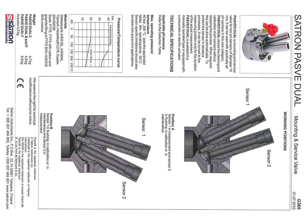
90 90
91 91
92 SATRON PASVE DUAL PASVE DUAL B (Welded on container or vertical pipe, body 15º) 92 Mounting & Service Valve PASVE DUAL T (Flow-through, threaded connection) PASVE DUAL D (Flow through, flange connection) G L Ø115 Ø (type AS) B L W L depends on the sensor type M10/15 K H PASVE DUAL D FLANGE Code Type W ØD H H ANSI 1" 150 lbs J ANSI 1" 300 lbs U ANSI 2" 150 lbs V ANSI 2" 300 lbs G DN25 PN T DN50 PN PASVE DUAL T THREAD Code Type (dim.k) B H " - NPT 1.5" - NPT 2" - NPT ØD Dimensions (in mm) Surface temperature European Directive Information Ambient temperature C Sensor connection Temperature class T6 T5 T4 ATEX directive (94/9/EC) Satron Instruments Inc. complies with the ATEX directive. European Pressure Equipment Directive (PED) (97/23/EC) - Sound Engineering Practice European Certification: II 3 GD Code A Sensor Standard sensor connection PG13.5 / Ø12 / length 120 mm
93 SATRON PASVE DUAL Selection Table PASVE DUAL Mounting type C On container or horizontal pipe, welded B On container or vertical pipe, body 15º, welded P Shape the body to be suitable to the pipe, welded F On flange T Flow-through, threaded connection D Flow-through, flange connection Process connection type, specified for mounting type F Flanges Flanges Code Type Code Type T DN50 PN40 (only H ANSI 4"150 lbs manual using) G ANSI 4"/300 lbs D DN80 PN40 E JIS 10K 80 J DN100 PN10/16 F JIS 40K 80 C DN100 PN40 A ANSI 3"/150 lbs B ANSI 3"/300 lbs 93 Mounting & Service Valve Wetted parts (C, B and P) Code Material none AISI316L (std.) 3 Hastelloy C276 4 AISI904L 6 Titanium 8 Duplex (EN ) K 254 SMO Wetted parts Code Material 2 AISI316L 3 Hastelloy C276 4 AISI904L 6 Titanium 8 Duplex (EN ) K 254 SMO G Process connection type, specified for mounting type T Threads Code Type NPT NPT NPT Process connection type, specified for mounting type D Flanges Flanges Code Type Code Type G DN25 PN40 U ANSI 2"/150 M DN40 PN40 V ANSI 2"/300 T DN50 PN40 K JIS 10K 25 H ANSI 1"/150 R JIS 10K 40 J ANSI 1"/300 S JIS 10K 40 N ANSI 1.5"/150 X JIS 10K 50 P ANSI 1.5"/300 L JIS 40K 25 Y JIS 40K 50 Seals 0 PTFE + 20C + 5Gr / FPM (std.) 1 PTFE 100% / FPM 2 PTFE +20C+5Gr / FFPM 3 PTFE 100% / FFPM Sensor connection A PG13,5 / Ø12 / 120 mm Pt100 temperature sensor 0 No sensor X With sensor (Measuring range C Specification example: PASVE DUAL C 2 0 A X AD3 1 E Z5 IEMC1 Wetted parts Code Material 2 AISI 316L 3 Hastelloy C276 4 AISI904L 6 Titanium 8 Duplex (EN ) K 254 SMO Wetted parts Code Material 2 AISI316L 3 Hastelloy C276 4 AISI904L 6 Titanium 8 Duplex (EN ) K 254 SMO 4 PTFE + 20C + 5Gr / FPM+AISI316 / PTFE 50 % (Hard) 5 PTFE 100% / FPM+AISI316 / PTFE 50% (Hard) 6 PTFE 100% / FPM + PVDF 100% (Hard) Actuator MD No actuator (manually operated AE1 Electric actuator 230 V 50 Hz AD Double-action actuator AE3 Electric actuator 115 V 60 Hz AS Spring-return actuator A0 No actuator, fittings to the actuator Solenoid for actuator (only for actuator types AD and AS) 0 No solenoid valve 2 24 V DC 2.5 W (also EEx dm) 4 28 V DC 0.4 W (EEx ia) V AC 50 Hz 2 W (as standard) V AC 60 Hz 2 W Solenoid explosion proof 0 No explosion proof 2 EEx ia IIC T6 (only 28V) 1 EEx m II T5 3 EEx dm IIC T5/T6 (only 24V) Position switches 0 None A Position switch EEX ib IIC T5/T6 X Equipped with position switches E Position switch NAMUR, DIN Special options Z1 For oxygen use Z5 Diamond-coated ball Z2 Process side flushing Z3 Actuator (AS) reverse action Documentation Installation and operating instructions Material certificates IE English 0 No material certificate IF Finnish MC1 SFS-EN (DIN ) MC2 SFS-EN (DIN ) MC3 SFS-EN B (DIN B)
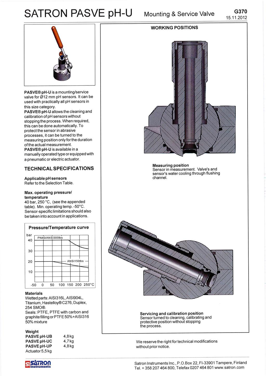
94 94
95 95
96 96
97 97


 (subject to type of rubber septum selected) Max.")
98 PASVE SC/SF/SH/SP/ST Sampling Valve The PASVE SC/SF/SH/SP/ST is a miniature ball valve which readily accepts commercially available septum hygienic rubbers. The PASVE SC/SF/SH/ SP/ST provides you with the opportunity of taking hygienic samples from your process without interrupting the process. 98 G The PASVE SC/SF/SH/SP/ST can be used in any industrial process where it is necessary obtain a sample from the process which is not influenced or contaminated from any outside disturbances. The PASVE SC/SF/SH/SP/ST is a member of the Satron PASVE Series, which is commonly used with ph probes, oxygen sensors and Satron's high precision patented pressure and level transmitters. Technical Specifications Material Housing: AISI316L Gasket: PTFE / Silicone rubber seal Max. process pressure: 10 bar (150 psi) (subject to type of rubber septum selected) Max. process temperature: 120 C (250 F) (subject to type of rubber septum selected) Operation Position of taking a sample Taking a sample Changing the rubber septum PROCESS PASVE is the registered trademark of Satron Instruments Inc. We reserve the right for technical modifi cations without prior notice. Satron Instruments Inc., P.O.Box 22, FIN Tampere, Finland Tel , Telefax ,


 PASVE SF - Flange SF D110 - Outer diameter of fl ange")

99 PASVE SC/SF/SH/SP/ST Sampling Valve 99 G PASVE SC PASVE SC - 10 PASVE SP PASVE SH - Tri-Clamp, sizes DN25/DN38 and DN40/51 PASVE ST - Tuchenhagen, sizes DN25/DN32 and DN40/DN50 PASVE SF - Flange SF D110 APV-FN Flange SF D110 Dimensions (in mm) PASVE SF - Flange SF D110 - Outer diameter of fl ange is 110 mm Ø x 90 Ø11 PASVE SF - Flange SF D110 APV-FN Outer diameter of fl ange is 110 mm 4,3 2 Ø55,35 Ø64 Ø70,6 Ø x 90 Ø11
100 PASVE SC/SF/SH/SP/ST Dimensions (in mm) 100 Sampling Valve G SC = 5,5 SC-10 = Ø40 DN25/38 = Ø50,5 DN40/50 = Ø64 PASVE SC and SC - 10 PASVE SH (Tri-Clamp) - Sizes DN25/38 and DN40 / 51 Ø68 Ø71 Ø50 Ø53 Ø66 Ø84 PASVE ST (Tuchenhagen) - Size DN40 / 50 PASVE ST (Tuchenhagen) - Size DN25 / 32 PASVE SP Ø25


101 PASVE SC/SF/SH/SP/ST Sampling Valve 101 G Upgrade kit Part no. Part name Order code Bearing Special nut V Valve ball V Valve body LV Gasket O-ring Ø11,3 x 2,4 NBR Rubber septum Rubber seal V T T T V V T Upgrade kit, assembly M Protection kit Part no. Part name Order code Pull-out sleeve Spring Locking sleeve Retaining screw M4x4 DIN916 A4 T T T Protection kit 2, assembly M
102 102 Mounting couplings for Satron VG transmitter G Thread and clamp couplings Standard coupling G1 Order codes: - AISI316L M Duplex M Hastelloy C276 M Titanium M Standard coupling G1 with cleaning Order codes: - AISI316L M Duplex M Hastelloy C276 M Titanium M Hygienic coupling G1 Order codes: - AISI316L M Duplex M Hastelloy C276 M Titanium M Coupling G1 / G½A Order code: - AISI316L M Coupling G1 / ½ -NPT Order code: - AISI316L M Coupling G1 / G¾A Order code: - AISI316L T Coupling G1 / G1A Order codes: - AISI316L M Hastelloy C276 M Coupling G1 / G1¼A Order code: - AISI316L M Coupling G1 / G1½A Order code: - AISI316L T Satron Instruments Inc., P.O.Box 22, FI Tampere, Finland Tel , Telefax ,
103 103 Mounting couplings for Satron VG transmitter G Coupling G1 / G2A Order code: - AISI316L M Coupling G1 / 2-NPT Order code: - AISI316L M Coupling G1 / M44 x 1,25 (PMC) Order codes: - AISI316L M Hastelloy C276 M Coupling G1 / Hygienic coupling ISO2852 standard: Order codes (AISI316L): - Tri-Clamp 25/38 M Tri-Clamp 40/51 M Tri-Clamp 63,5 M Tri-Clamp 70 M Tri-Clamp 76,1 M Tri-Clamp 88,9 M Tri-Clamp 101,6 M Tri-Clamp 114,3 M Tri-Clamp 139,7 M Coupling G1 / Hygienic coupling SMS standard: Order codes (AISI316L): - SMS 38 M SMS 51 M Coupling G1 / Hygienic coupling DIN11851/11887 standards: Order codes (AISI316L): - DN40 M DN50 M DN65 M Coupling G1 / PMC 1,5" Order codes: - AISI316L M Hastelloy C276 M Extended coupling G1 with cleaning Order code: - AISI316L M Extended coupling G1 Order codes: - AISI316L M Hastelloy C276 M
104 104 Mounting couplings for Satron VG transmitter G Coupling G1 / G½A + drain valve Order code: - AISI316L M Coupling G1 for pipes DN15 - DN25 and clean liquids Order codes (AISI316L): - DN15 M DN20 M DN25 M Coupling G1 for pipes DN15 - DN40 Order codes (AISI316L): - DN15 M DN20 M DN25 M DN32 M DN40 M Coupling G1 / G½A (male) with mounting bracket Order code: - AISI316L M Coupling G1 / ½ - NPT (male) with mounting bracket Order code: - AISI316L M Coupling G1 / G½ (female) with mounting bracket Order code: - AISI316L M Coupling G1 / ½ - NPT (female) with mounting bracket Order code: - AISI316L M550393N Coupling G1 / Ø52,5 L=38 (SMS nut fixing, size 38, thread 60 x 1/6) Order code: - AISI316L M
105 105 Mounting couplings for Satron VG transmitter G Ø45 G1 19,5 Coupling G1 / SMS-SI - with extension Order codes (AISI316L): - SMS-SI38 M SMS-SI51 M Coupling G1 / Sandvik-clamp - Extension length 54,5 mm Order codes: - AISI316L M Duplex M Hastelloy C276 M Thread sleeve G1 (eg. for coupling M ) Order codes: - AISI316L M Hastelloy C276 M Flange couplings FLANGE TYPE DN25 PN40 DN40 PN40 DN50 PN40 DN80 PN40 DN100 PN40 ANSI1"150LBS ANSI1"300LBS ANSI2"150LBS ANSI2"300LBS ANSI3"150LBS ANSI3"300LBS ANSI4"150LBS ANSI4"300LBS COUPLING TYPE G1 std. G1 std. HC G1 hyg. G1 hyg. HC G1 Exi G1 Exi HC ORDER CODE ORDER CODE ORDER CODE ORDER CODE ORDER CODE ORDER CODE M M M M M M M M M M M M M M M M M M M M M M M M M M M M M M M M M M M M M M M M M M M M M M M M M M M M M M M M M M M M M M M M M M M M M M M M M M M M M M FOR GASKET CHANNEL : (DIN 2512N) DN25 PN40 DN50 PN40 DN80 PN40 M M M M M M M M M M M M M M M M M M Multidimensional flange coupling ØD COUPLING TYPE D G1 std. ORDER CODE M M G1 std. HC G1 hyg. G1 hyg. HC G1 Exi G1 Exi HC ORDER CODE ORDER CODE ORDER CODE M M M M ORDER CODE M ORDER CODE M M M M M

106 106 Mounting couplings for Satron VG transmitter ØD G Pipe size Dim. Ødu Dim. A Dim. Dim. Order code Material B ØD G Ø25 Ø20.5 Ødu DN M xx +0.2 the order +0.5 Should be mentioned in DN M xx the order DN Should be mentioned in +0.2 M xx the order DN Should be mentioned in +0.2 M xx the order DN Should be mentioned in M xx the order DN M xx Should be mentioned in the order A B Plastic coupling G1 for plastic pipes DN15 - DN50 Coupling G1 / Varivent TN Order code (AISI316L): - DN25 M DN50/40 M DN80/65 M Hygienic Coupling G1 / Ø38 Order code: - AISI316L M Hastelloy C M HC Seal plug assembly for Satron coupling G1 By seal plug the coupling can be closed tightly. Order code: - AISI316L M EHEDG M Welding assistant for Satron coupling G1. It is always recommendable to use the welding assistant while welding the coupling to prevent any distortions due to heat. Order code: - Brass M Special adapter for Satron couplings G1. By using this adapter it is possible to install the sensor head ca. 3mm deep into the coupling. Order code: - EN (Duplex) M Seal for Satron couplings G1. Enables to seal the leaking metal to metal taper. Order code: - PTFE T546022
107 Mounting couplings for Satron VT Transmitters 107 G Process couplings with DIN 3852-X thread Order code: AISI316L d4 A a1 Du 0 Order code Thread A Du Length L d4 a1 M G½ Ø30 18,5 Ø M G1 Ø Ø M G1½ Ø Ø M G1½ Ø Ø M G2 Ø75 33 Ø L Process couplings with NPT thread Order code: AISI316L Order code Thread A Du Length L A L Du M ½-14 NPT Ø28 14 M ¾-14 NPT Ø35 16 M ½ NPT Ø M ¼ - 11½ NPT Ø M ½ - 11½ NPT Ø M ½ NPT Ø G¼ Ø20 G3/8 Ø Process coupling DIN G¼ Order code: - AISI316L M Process coupling G½ Order code: - AISI316L M Ø27 G½ Ø18,3 Ø30 Ø26,5 Ø33,5 G½ Ø28 30 Process coupling DIN G½ Order code: - AISI316L M ,5 25,5 Process coupling DIN X - G½, for transmitter with two o-ring Order code: - AISI316L M Process coupling PMC 1" Order code: - AISI316L M Satron Instruments Inc., P.O.Box 22, FI Tampere, Finland Tel , Telefax ,
108 Mounting couplings for Satron VT Transmitters 108 G ØD out Ø G½ T-coupling DIN 3852-X-G½ Order codes: AISI316L Pipe size Dim. ød out Dim. A Dim. B Dim. C Dim. Ø d Dim. E Order code B A Ød C DN M DN M DN M Other size, please contact Satron Instruments Inc. E Coupling flange DIN 3852-X-G½ - for the transmitter with two o-rings Tilauskoodit: AISI316L ORDER CODE TYPE OF FLANGE G½ M DN25 DN 25 PN 40 M DN40 DN 40 PN 40 M DN50 M DN80 DN 50 PN 40 DN 80 PN 40 M DN100 DN 100 PN 16 M M M M M M M M ANSI 1" 150 LBS ANSI 1" 300 LBS ANSI 2" 150 LBS ANSI 2" 300 LBS ANSI 3" 150 LBS ANSI 3" 300 LBS ANSI 4" 150 LBS ANSI 4" 300 LBS L Special flanges, please contact Satron Instruments Inc. A Welding assistant: Order codes L A Order code M M M M M M Thread A Dim. L Position, form and size G½A 25 6-k, AV22 G¾A 15 6-k, AV27 G1A 20 6-k, AV36 G1 ¼A 35 4-k, AV22 G1 ½A 35 4-k, AV22 G2A 35 4-k, AV22
109 109
*&* 9B:9':& '&* ***' '5)* C & ** ;1 &")

/' 6 ' 72 * % & **)*& '!")
110 )*!" #" $ %&' (!5& *& & 4&*& &8 '))9.&7:;0<3=>* &&?3 0,32>*& &@33 ' & 9A&1 **: ')*&* 9B:9':& '&* ***' '5)* C & ** ;1 & && * ' && ' %& ** * *&* ' &&D * D! * * *& 1* %0E3%0<3 =>?3 0,32> *& 7,3 %0E3%0<3 =>*& 2, 110! "!" # $% & ' & ( &' % &)& # " & **&* &* ' **' )**+,-* ***)** &,-***.' /* 0&/ 1& 23# 4& 5** & &' % ***)/' 6 ' 72 * % & **)*& '!+", $ '" -"," )& * ***& )' & **& 5 &%. 1 & &.,/!"#$%$"&!"#$%$"'''


111 111! "! #,! " #$ $!%&', '!!"#$ $ "%%&'( ) "!! $ $%!!%$ * $! "%%&'( *" $ % "%%&'( *" "+$% "* " "+$%,!!* " &&!$$%+ &'("""$$ $%&' (' - "&.&/!!+ ' "+"!&/! &$ /&!'" '!+ ($&$&$$!"$' $/"0$$!!$"1 / $!" '/!"$$/ &$&$(!!$'&+ "!!$ )*%'' $+ $&* )&( $ '&
112 112 # $ $$ %& '&(&&! "#$% &' && ( &' && &' && "#)* ++# # & "#",(+ ((&, + -( * --%&-'&,. #)-. #" /01) ##. #2 /01) $ + +(567 + ) + +(567 + " + +( !" 4

113 113 SATRON HPS Hydraulic Pressure Seal BP The Hydraulic Pressure Seal SATRON HPS is used in pressure measurement applications where the process medium is aggressive and it is necessary to protect the wetted parts of measuring transmitters. Processes' hygienic requirements may also necessitate the use of the pressure seal. In addition, the pressure seal has to be used when the process temperature exceeds the transmitter's specifications. Technical specifications Process connections DN25,DN50, DN80, DN100 (EN ,flange type 05, facing type B), (DIN 2501, form D) ANSI2" and 3" (ANSI B16-5) JIS 50, 80, 100 (JIS B 2220) Sandvik Clamp connector DN65 TRI-Clamp 1½", 2" and 2,5" (38/51/ 63,5 mm, ISO2852) SMS38 and SMS51 DIN11851 DN25... DN50 Other options available on separate order. Fill fluids Silicone oil DC200 for process and food industry applications Neobee M20 for food industry applications Inert oil (e.g. Fomblin Y04 or Halocarbon) for oxygen and chlorine applications Silicone oil DC705 for high-temperature and vacuum measurement applications Gaskets (Sanitary Seal) EPDM, FPM (Viton ) and PTFE Process pressures PN10/16, PN40, PN64 and PN and 300 lbs 10K and 50K Sandvik Clamp: PN64 TRI-Clamp: PN40 SMS and DIN11851 PN25 PN40 Fill fluid properties Fill fluid Temperature range/ C DC200 Silicone oil Density g/cm Thermal expansion coefficient/ 1/ C Viscosity (25 C) cst(mm 2 /s) 9.5 Measurement ranges Above 25 mbar span, depending on the measuring diaphragm's size and the process pressure. DC705 Silicone oil Inert oil Materials HPS body: EN (AISI 316) Process coupling: EN (AISI 316L) Neobee M Fill fluid steam pressure curves (specified by manufacturers) Capillary tube Capillary: EN (AISI 316) Casing: EN (AISI 316) Length selectable between 2 and 20 m. Recommendation: As short as possible. The capillary's minimum permissible bending radius is 50 mm. We recommend capillaries of equal length for differential pressure measurements in varying temperature conditions. Diaphragm materials EN (AISI 316L), CoNi-alloy, Duplex (EN ), Hastelloy C22 (EN ) / C-276 (EN ), Inconel 600 (EN ), Monel 400 (EN ), Nickel (EN ), Tantalum, Titan Ti-II (3.7035) and Zirkonium Temperature/ C Pressure/mbar abs. DC200/10 Halogarbon Neobee M Satron Instruments Inc., P.O.Box 22, FI Tampere, Finland Tel , Telefax ,

114 SATRON HPS Hydraulic Pressure Seal HPS types: construction 114 BP SATRON HPS D - Mounted between two flanges SATRON HPS TRI-C - Mounted on Tri-Clamp (ISO2852) - Sanitary seals SATRON HPS F - Flange-mounted pressure seal SATRON HPS SMS - Sanitary seals - Female Rd-thread SATRON HPS E - Flange-mounted with extension SATRON HPS DIN Sanitary seals - Female Rd-thread SATRON HPS S - Mounted on Sandvik Clamp - Sanitary seals SATRON HPS SMS-SI - Sanitary seals - Female Rd-thread 2
115 SATRON HPS Hydraulic Pressure Seal Mounting dimensions d 2 BP ød 4 ød b E b k D Type F Type E Ød1 120 Type D FLANGE SIZE ISO DN25 PN10/16 ISO DN25 PN40 ISO DN25 PN64 ISO DN25 PN100 ISO DN50 PN10/16 ISO DN50 PN40 ISO DN50 PN64 ISO DN50 PN100 ISO DN80 PN10/16 ISO DN80 PN40 ISO DN80 PN64 ISO DN80 PN100 ISO DN100 PN10/16 ISO DN100 PN40 ANSI 2" 150 lbs ANSI 2" 300 lbs ANSI 3" 150 lbs ANSI 3" 300 lbs ANSI 4" 150 lbs ANSI 4" 300 lbs JIS 10K-50 JIS 40K-50 JIS 10K-80 JIS 40K-80 JIS 10K-100 JIS 40K-100 FLANGE CODE D1A D1B D1C D1D D2A D2B D2C D2D D3A D3B D3C D3D D4A D4B A2A A2B A3A A3B A4A A4B J2A J2B J3A J3B J4A J4B FLANGE DIMENSIONS HOLES EXTENS. b D Ød 4 Ød 1 Kpl d 2 k Ød CODE E
116 116 SATRON HPS Hydraulic Pressure Seal BP Selection table : Flanged Seal HPS Process connection type D Pancake F Flanged E Flanged with extension Process connection standad D DIN (Deutsches Institut für Normung) A ANSI/ASME B16.5 (American National Standards Institute J JIS (Japanese Industrial Standards) Process connection size DIN ANSI JIS " " " 100 Pressure class of process connection (maximum working pressure) DIN ANSI JIS A PN10/16 150lbs 10K B PN40 300lbs 40K C PN D PN Extension length 0 No extension (only codes D and F) 2 Extension 51 mm (only code E) 4 Extension 102 mm (only code E) 6 Extension 152 mm (only code E) Flange material / in type E also extension material 2 EN (AISI316L) 3 Hastelloy C-276 (EN ) 8 Duplex (EN ) Diaphragm material 1 Nickel (EN ) (***) 7 CoNi-alloy 2 EN (AISI316L) 8 Duplex (EN ) 3 Hastelloy C-276 (EN ) H Hastelloy C22 (EN ) 4 Inconel 600 (EN ) M Monel 400 (EN ) 5 Tantalum Z Zirkonium (***) 6 Titan TI-II (EN ) (***) Diaphragm thickness E 0.05 mm (*) F 0.10 mm (**) Diaphragm coating 0 No coating P PTFE sintered 9 Gold / Rhodium Y Diamond Fill fluid S Silicone oil DC200 A Neobee M20, oil for food industry G Inert oil D Silicone oli DC705 (*) = Not Inconel, Monel, Nickel or Zirkonium (**) = Not Tantalum (***) = Not connection type E (with extension) 4
117 117

118 118 SATRON HPS Hydraulic Pressure Seal BP Mounting dimensions type SMS Mounting dimensions type DIN11851 A A g ØD Ød6 Size Dimensions ØD A Thread Rd 60 x 1/6 Rd 70 x 1/6 Size DN25 PN25 DN32 PN25 DN40 PN25 DN50 PN25 Dimensions Ød 6 g A , Thread Rd 52 x 1/6 Rd 58 x 1/6 Rd 65 x 1/6 Rd 78 x 1/6 Mounting dimensions type SMS-SI SMS-SI couplings : A E L1 L2 ØD Ød ØD Size SI38 SI51 ØD Dimensions A E Thread Rd 60 x 1/6 Rd 70 x 1/6 for pipe Size L Dimensions Ød L2 38, for vessel ØD Thread Rd 60 x 1/6 Rd 70 x 1/6 6
119 SATRON HPS Hydraulic Pressure Seal Hydraulic Pressure Seal Connections 119 BP Capillary connection Seal on Low or High pressure side of Differential PressureTransmitter, code H or K Same seal on both High and Low pressure sides of Differential Pressure Transmitter, code L Selection table Capillary connection type H Seal on High pressure side of Differential Transmitter K Seal on Low pressure side of Differential Transmitter L Same seal on both High and Low pressure side of Differential Transmitter M Seal on High pressure side of Pressure Transmitter, process connection G½A Capillary length (m) Mounting bracket for transmitter 0 No mounting bracket 1 Angle mounting bracket 2 Mounting plate Documentation IE English IF Finnish Material certificate 0 No material certificate MC1 SFS-EN (DIN ) MC2 SFS-EN (DIN ) MC3 SFS-EN B (DIN B) Seal on High pressure side of pressure transmitter, process connection G½A, code M 7
120 SATRON HPS Hydraulic Pressure Seal Hydraulic Pressure Seal Connections 120 BP Direct mounted connection Seal on High pressure side of Differential Pressure Transmitter, angle model, code P Seal on High pressure side of Differential Pressure Transmitter, straight model, code R Selection table Direct mounted connection type P Seal on High pressure side of Differential Transmitter, angle model R Seal on High pressure side of Differential Transmitter, straight model S Seal on High pressure side of Pressure Transmitter, process connection G½A, straight model Documentation IE English IF Finnish Material certificate 0 No material certificate MC1 SFS-EN (DIN ) MC2 SFS-EN (DIN ) MC3 SFS-EN B (DIN B) Seal on High pressure side of Pressure Transmitter, process connection G½A, straight model, code S 8
121 121
122 SATRON HPS Hydraulic Pressure Seal Type SMS-SI Type DIN11851 O-ring Pressure seal Gasket Pressure seal 122 BP Coupling Tyyppi SMS Coupling Gasket Pressure seal Coupling Specification example: SATRON HPS KA23E0S10-M52IE0 - Process connection type, sanitary DN25 DIN Material of body: EN (AISI316L) - Diaphragm material: Hastelloy C-276 (EN ) - Diaphragm thickness: 0.05mm - No diaphragm coating - Fill fluid: silicone oil - Material of process gasket: EPDM - No mounting parts - Capillary type connection: - Seal on high pressure side of Pressure Transmitter - Capillary length 5m - Mounting bracket for transmitter, type mounting plate - Documentation: English - No material certification Recommended minimum process pressure for vacuum applications T proc. C Minimum pressure for different fill fluids (kpa, abs.) DC200 Inert oil 100 cst Hastelloy is the registered trademark of Haynes International. Teflon is the registered trademark of E.I. du Pont de Nemours & Co. Viton is the registered trademark of DuPont Dow Elastomers. We reserve the right for technical modifications without prior notice. 10

123 123 SATRON HPS BA / BB Hydraulic Pressure Seal EN The Hydraulic Pressure Seal SATRON HPS is used in pressure measurement applications where the process medium is aggressive and it is necessary to protect the wetted parts of measuring transmitters. Processes' hygienic requirements may also necessitate the use of the pressure seal. In addition, the pressure seal has to be used when the process temperature exceeds the transmitter's specifications. Technical specifications Process connections Thread M45 x 2 Process pressures PN200 Measurement ranges Above 25 mbar span, depending on the measuring diaphragm's size and the process pressure. Materials HPS body: EN (AISI 316L), EN (Duplex) Capillary tube Capillary: AISI 316 Casing: AISI 316 Length selectable between 2 and 20 m. Recommendation: As short as possible. The capillary's minimum permissible bending radius is 50 mm. We recommend capillaries of equal length for differential pressure measurements in varying temperature conditions. Fill fluid properties Fill fluid Temperature range/ C DC200 Silicone oil DC705 Silicone oil Inert oil Neobee M Density g/cm Thermal expansion coefficient/ 1/ C Viscosity (25 C) cst(mm 2 /s) Diaphragm materials AISI 316L (EN ), CoNi-alloy, Duplex (EN ), Hastelloy C22 / C-276 (EN ), Inconel 600 (EN ), Tantalum Fill fluids Silicone oil DC200 for process and food industry applications Neobee M20 for food industry applications Inert oil (e.g. Fomblin Y04 or Halocarbon) for oxygen and chlorine applications Silicone oil DC705 for high-temperature and vacuum measurement applications Gaskets FPM (Viton ) Recommended minimum process pressure for vacuum applications T proc. C Minimum pressure for different fill fluids (kpa, abs.) DC200 Inert oil 100 cst Satron Instruments Inc., P.O.Box 22, FI Tampere, Finland Tel , Telefax ,
124 124 SATRON HPS BA / BB Hydraulic Pressure Seal Selection table: M45 x 2 Seal EN Process connection type BA M45 x 2 with o-ring BB M45 x 2 with o-ring + metal/metal taper HPS Body material, wetted parts 2 AISI316L (EN ) 8 Duplex (EN ), std. 3 Hastelloy C-276 (EN ) Diaphragm material 2 AISI316L (EN ) 3 Hastelloy C276 (EN ) 4 Inconel 600 (EN ) 5 Tantaali 8 Duplex (EN ) Diaphragm thickness E 0.05 mm F 0.10 mm Diaphragm coating 0 No coating P PTFE sintered 9 Gold / Rhodium Y Diamond Fill fluid S Silicone oil DC200 G Inert oil A Neobee M20, oil for food industry D Silicone oil DC705 Mounting parts 0 No mounting parts 1 Coupling 2 Pasve BA mounting valve, specify separately in the order 2

125 125 SATRON HPS BA / BB Hydraulic Pressure Seal EN Mounting dimensions, type BA Mounting dimensions, type BB 3
126 126 SATRON HPS BA / BB Hydraulic Pressure Seal EN Hydraulic Pressure Seal Connections Capillary connection Seal on Low or High pressure side of Differential PressureTransmitter, code H or K Same seal on both High and Low pressure sides of Differential Pressure Transmitter, code L Selection table Capillary connection type H Seal on High pressure side of Differential Transmitter K Seal on Low pressure side of Differential Transmitter L Same seal on both High and Low pressure side of Differential Transmitter M Seal on High pressure side of Pressure Transmitter, process connection G½A Capillary length (m) Mounting bracket for transmitter 0 No mounting bracket 1 Angle mounting bracket 2 Mounting plate Documentation IE English IF Finnish Material certificate 0 No material certificate MC1 SFS-EN (DIN ) MC2 SFS-EN (DIN ) MC3 SFS-EN B (DIN B) Seal on High pressure side of pressure transmitter, process connection G½A, code M 4
127 127 SATRON HPS BA / BB Hydraulic Pressure Seal Hydraulic Pressure Seal Connections EN Direct mounted connection Seal on High pressure side of Differential Pressure Transmitter, angle model, code P Seal on High pressure side of Differential Pressure Transmitter, straight model, code R Selection table Direct mounted connection type P Seal on High pressure side of Differential Transmitter, angle model R Seal on High pressure side of Differential Transmitter, straight model S Seal on High pressure side of Pressure Transmitter, process connection G½A, straight model Documentation IE English IF Finnish Material certificate 0 No material certificate MC1 SFS-EN (DIN ) MC2 SFS-EN (DIN ) MC3 SFS-EN B (DIN B) Seal on High pressure side of Pressure Transmitter, process connection G½A, straight model, code S 5
128 128 SATRON HPS BA / BB Hydraulic Pressure Seal Specifi cation example: SATRON HPS BB88E0S0-M52IE0 - Process connection type: Thread M45 x 2 with o-ring + metal/metal taper - Body material: EN , Duplex - Diaphragm material: EN , Duplex - Diaphragm thickness: 0.05mm - No diaphragm coating - Fill fl uid: silicone oil - No mounting parts - Hydraulic Pressure Seal Connections: Capillary type connection - Seal on High pressure side of pressure transmitter, process connection G½A, - Capillary length 5m - Mounting bracket for transmitter, type mounting plate - Documentation: English - No material certification EN Welding the coupling 52,5 Welding plug, brass M Ø60 Welding sequence Hastelloy is the registered trademark of Haynes International. Teflon is the registered trademark of E.I. du Pont de Nemours & Co. Viton is the registered trademark of DuPont Dow Elastomers. We reserve the right for technical modifications without prior notice.
129 129

130 130 Actuator tors and accessories 5/04 April 30, 2010 ACTUATORS - PISTOR 75 pneumatic power cylinder... Spec. EZ510 Satron Instruments Inc., P.O.Box 22, FIN Tampere, Finland Tel , Telefax ,


131 PISTOR 75 The pneumatic PISTOR power cylinder can be used as an actuator in manual and automatic control of control valves and louvers. 131 pneumatic power cylinder EZ510 Febr. 15, 1989 Technical specification Piston diameter: Stroke S: Effective cross-sectional area of piston: Output force - for 3 bar supply pressure: - for 6 bar supply pressure: Output work (moment of force) - for 3 bar supply pressure: - for 6 bar supply pressure: Typical time for full stroke: Weight: Type PISTOR 75/150 PISTOR 75/ mm 75 mm 150 mm 300 mm 41 cm 2 41 cm N 1200 N 2400 N 2400 N 180 Nm 360 Nm 360 Nm 720 Nm 12 s 20 s 2.8 kg 3.4 kg Supply pressure: 3 to 6 bar. Control pressure range - with standard adjustment: 0.2 to 1.0 bar - on separate order: 0.4 to 0.9 bar spans. Operating temperature: -10 to +80 C Air consumption - for 3 bar supply pressure: 15 litres/min (at STP) - for 6 bar supply pressure: 25 litres/min (at STP) Max. error of adjustment: ± 2 %. Sensitivity: 0.3 %. Load effect - for a load change from 0 to 80 % of the max. force obtainable for the supply pressure in use, the effect is 4 % of max.stroke per 1000 N. Materials - body: light alloy with epoxy powder paint, bearing bush of bronze - piston rod: ground and polished AISI 316 acid-resistant steel - piston and 0-rings: silicone rubber (max. 80 C). Connections - 1/4-18NPSF female threads. We reserve the right to make technical changes without prior notice. Performance is indicated in accordance with IEC546 and IEC770 recommendations. Satron Instruments Inc., P.O.Box 22, FIN Tampere, Finland Tel , Telefax ,

")

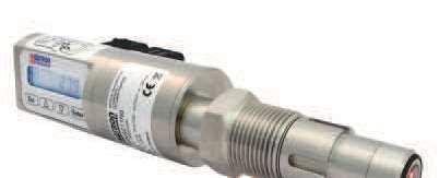
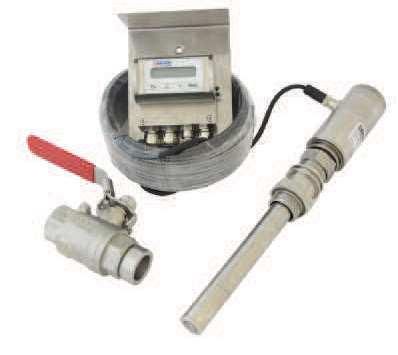
132 132!"#$% & " # " # & # " ' " # & ( ) *+, & -"./0./10 2 1!"#$%&%#'!"#$%&%#(((

133 SATRON VO Turbidity and solids content sensor SATRON VO turbidity and solids content analyzer is suitable for the measurement of different liquids. Savings can be obtained by using SATRON VO analyzer in process industries, e.g. the use of clean water can be minimized, the time used for the cleaning (CIP) will be shortened, the use of the end product (in dairy applications: milk) and the use of cleaning materials needed in the process can be optimized. The transmitter communicates digitally using the HART protocol. TECHNICAL SPECIFICATIONS Measuring range and span See Selection Chart. Zero and Span adjustment Zero elevation: Calibrated span is freely selectable on the specified range depending from the desired option. This can be made by using keyboard (display option) or HART 275/375 communicator. Damping - Time constant is continuously adjustable 0.01 to 60 s. Repeatability - 0.1% from maximum span. Temperature limits Ambient: -30 to +80 C Process: 0 to +100 C / +140 C (VOF) -5 to +100 C / +140 C (VOM & VOD) Shipping and storage: -40 to +80 C. Output 3-wire (3W), 4-20 ma Supply voltage Nominal 24 VDC, (21,6-27,6V) Humidity limits % RH EMC directive 2004/108/EC - EN :2005 CONSTRUCTION Materials: Sensing element 1) : AISI316L, Duplex (EN ), Hast. C276/C22, or Titanium Gr2. Surface quality: Polished Ra <0,8µm Lens: quartz glass, Safir glass or PC plastic Coupling 1) : AISI316L, Duplex (EN ), Hast.C276 or Titanium Gr2 Other sensing element materials: AISI316, SIS Pressure class: - PN40 - Test pressure -1 to 30 bar Housing with display, codes N0S & N0T: Housing: AISI303/316, Seals: Nitrilerubber and Viton, Nameplates: Polyester Housing with M12 connector, code H0T: Housing: AISI303/316, Seals: Viton and NBR. Housing with PLUG DIN connector, code H0S: Housing: AISI303/316, Seals: Viton and NBR. PLUG connector: PA6-GF30 jacket, Silicone rubber seal, AISI316 retaining screw. Connection hose between sensing element and housing Codes L and R : PUR signal cable or hose protected with PTFE/AISI316 braiding Calibration For customer-specified range with minimum damping. (If range is not specified, transmitter is calibrated for maximum range.) Electrical connections Housing with PLUG connector, code H0S: Connector type DIN model AF; Pg9 gland for cable; wire cross-section 0.5 to 1.5 mm 2. Housing with M12 connector, code H0T: M12 plug connector Housing with display, code N0S: Connector type DIN model AF; Pg9 gland for cable; wire cross-section 0.5 to 1.5 mm 2. Housing with display, code N0T: M12 plug connector I/O-connections bout1-3 Relay, grounding contact Maximum voltage 35 V Maximum current 50 ma Maximum leakage current 10 µa bin1-3 NC (no connection) OFF V ON Minimum values for switch in use Voltage 16 V Current 4 ma Leakage current 1 ma Current output1 Range Maximum load Factory setting ma 600 Ω ma Current output2 Internal power supply Current output 2 has same ground as binary IO Maximum load 400 Ω Range ma Factory setting ma External power supply Current output 2 is galvanically isolated Maximum supply voltage 35 VDC Range ma Factory setting ma Maximum load, See picture below Maximum isolation voltage 100 VDC Process connections - With G1 connecting thread - Tri-Clamp 25/38 and 40/51 Protection class: See Selection chart. Weight Housing with PLUG DIN43650 connector (H0T ): Housing with M12 connector (H0S ): Housing with display (N0S & N0T): Remote Housing (L): Remote sensor (R): Min. load using HART communication 250 R R max = Supply voltage -5 V I max BA200 rev kg 0.9 kg 1.3 kg 2.5 kg 2.5 kg I max = 20,5 ma I max = 22,5 ma (when the alarm current 22,5 ma is on) Current output 2 External power supply 1) Parts in contact with process medium Satron Instruments Inc., P.O.Box 22, FI Tampere, Finland Tel , Telefax ,
134 SATRON VO Turbidity and solids content sensor Dimensions and Housing types VOM 134 BA200 rev G1A G1A H0T-Housing N0S-Housing PG G1A L-Housing Standard = PVC 10 meter PG9 std.
135 135 SATRON VO Turbidity and solids content sensor BA200 rev Tri-Clamp 25/38 ja 40/51 VOM with Tri-Clamp process connections, codes TA and TB NR Housing Standard = 10meter PVC G1A VOM with remote sensor, housing type code R


136 136 BA200 rev. 9.6 SATRON VO Turbidity and solids content analyzer Dimensions and housing type VOF H / B1-housing L / B1-Housing Standard = 15 meter VOF with valve Dimensions and housing type VOD For easy installation the VOD is standard equipped with Tuchenhagen Type N but is is available with many different process connections. The process pipe is NOT included. Contact Satron for other possibilities, the picture above is a VOD equipped with G1" process connection, and a pipe with 51 Tri-clamp.
137 SATRON VO Turbidity and solids content analyzer Instructions and spare parts that are according and within the 3-A appliance 137 BA200 rev Welding the coupling These instructions apply to hygienic welded couplings; welding the G1 standard coupling is described here as an example. Place the coupling in the mounting hole as shown in Fig Make sure the leakage detection port is down. Then weld with several runs so to prevent the coupling s oval distortion and tightness problems. The inside welding must be cleaned, and polished with an end result of Ra <0,8 The analyzer must be out of the coupling while the coupling is welded.you can use the shut off plug shown in Fig. 1 5 to shut the coupling. The plug protects the coupling s sealing face and permits the starting of the process without the transmitter. It is always recommendable to use the welding assistant (M ) while welding the coupling to prevent any distortions due to heat. Do not make weld grounding via any analyzer's body! Mounting the analyzer on the coupling Welding Sequence Polished Ra <0,8 Welding assistant M Procedure Make sure that the coupling s sealing face is clean. Remove the orange protective plug from the analyzer head. Insert the analyzer in a straight line into the coupling, so that the guide groove on the transmitter aligns with the stop pin on the coupling. The analyzer settles into position when the groove and pin are aligned, and will be prevented from rotating in the coupling. When inserting the analyzer, be careful not to damage the edge of the lens on the edges of the coupling or on the end of the stop pin! Lock the transmitter in position by screwing the hex nut fully home. Finger tightness is sufficient to tighten the sealing faces. However, we recommend final tightening with a tool to eliminate the effect of vibration and other such factors. Apply 60±20 Nm torque. Do not use sealing tape etc. on threaded connection! Spare parts No. Part name Order code Note 1 O-ring EPDM A Class II (Do not exceed above 8% fat content). 1 O-ring FPM (Viton ) A Class I 1 O-ring FFPM(Kalrez ) A Class I 2 Sticker T Plug cover DIN43650 T Plug cover M12 T /G1" Welding adapter M A 5 45/G1" Welding adapter M548101A 6 Tuchenhagen / Varivent DN25 M A 6 Tuchenhagen / Varivent DN50 M A 6 Tuchenhagen / Varivent DN65,5 M A 7 Tri-clover 25/38 ISO2852 M A 7 Tri-clover 40/51 ISO2852 M A 7 Tri-clover 63.5 ISO2852 M A
138 138 SATRON VO Turbidity and solids content analyzer BA200 rev Housing with display, code N Keyboard : Esc = Press Esc move back towards the top of the main menu. = Use the UP arrow key to move up on the current menu level or to increase the selected parameter value. = Use the DOWN arrow key to move down on the current menu level or to decrease the selected parameter value. Enter = Press ENTER to move to a lower level in a menu or to accept a command or parameter value Wiring Housing with M12-connector, code HT Wiring Housing with PLUG DIN43650-connector, code HS Wiring Housing with PLUG DIN and M12-connector, test connector box, code HT & HS
139 139 SATRON VO Turbidity and solids content analyzer BA200 rev Wiring Housing with display and PLUG DIN43650-connector, code NS Wiring Housing with display and M12-connector, code NT Wiring Remote electronics housing with display, code L
140 SATRON VO Turbidity and solids content analyzer Selection Chart 140 BA200 rev Adjustability Span, min Span, max VOM 1000 FTU 5000 FTU VOF (*) 50 FTU 1500 FTU VOD 50 FTU 1500 FTU Process temperature limits N Normal version C (VOM & VOD), C (VOF) H (**) High temperature C (VOM & VOD), C (VOF) Output S 4-20mA DC/HART for use with 230VAC 50Hz J 4-20mA DC/HART for use with 110VAC 60Hz Material of wetted parts Body 2 AISI316L 3 Hast. C Titanium Gr2 8 Duplex (EN ) 9 Peek Lens 2 Sapphire glass 4 Spinel Seal 3A (***) EPDM Class II 2 FPM (Viton ) Class I 3 FFPM (Kalrez ) Class I Housing type N Housing with display and pushbuttons H Housing with, no display, (only one ma output) L Remote electronics housing with display Probe type 0 No remote probe R Remote measuring probe (not available with L housing), IP68 Connection type S DIN43650 with PG9, IP66 T M12, IP67 V PG9 (always with L housing), IP66 Cable Material 0 No VOD, L or R selected 1 PUR cable. 2 (*) AISI316L braided PTFE hose. 3 Steel reinforced PUR hose. 4 PVC cable Cable length 0 No VOD or L, R option selected 1 5 M M. (PUR std.) 5 25 M M. (PVC std.) 4 20 M.... Light source 2 365nm 4 540nm 6 640nm 8 950nm 3 460nm 5 580nm 7 880nm Process connections G1 Standard G1A thread + Oring TA Tri-Clamp 25/38 (ISO 2852) TB Tri-Clamp 40/51 (ISO 2852) TN Tuchenhagen "N" type DN50 HX (*) Fixed mounting tube, (specify length) B1 (*) G1A ball valve insertion. Extension 19cm diameter ø 24mm BX (*) G1A ball valve insertion. Extension by request diameter ø 24mm Documentation Calibration certificate AE English Installation and operating instructions IE English IF Finnish FR French Material certificates 0 No material certificate MC1 Raw material certificate without appendices, in accordance with SFS-EN (DIN ) standard MC2 Raw material certificate for wetted parts, in accordance with SFS-EN (DIN ) standard MC3 Raw material certificate for wetted parts, in accordance with SFS-EN B (DIN B) standard * Not EHEDG certified & Not within the 3A approval ** Only in combination with Quartz, Sapphire lens and Kalrez Seals. And only 880nm *** Do not exceed above 8% fat content. We reserve the right for technical modifications without prior notice HART is the registered trademark of HART Communication Foundation. Pasve is the registered trademark of Satron Instruments Inc. Hastelloy is the registered trademark of Haynes International. Viton is the registered trademark of DuPont Down Elastomer. 3-A is a registered mark owned and administered by 3-A SSI.
141 SATRON VOA Turbidity and solids content sensor SATRON VOA turbidity and solids content analyzer Is suitable for the measurement of different liquids. Savings can be obtained by using SATRON VOA analyzer in process industries, e.g. the use of clean water can be minimized, the time used for the cleaning (CIP) will be shortened, the use of the end product (in dairy applications: milk) and the use of cleaning materials needed in the process can be optimized. The transmitter communicates digitally using the HART protocol. TECHNICAL SPECIFICATIONS Measuring range and span See Selection Chart. Zero and Span adjustment Zero elevation: Calibrated span is freely selectable on the specified range depending from the desired option. This can be made by using keyboard (display option) or HART 275/375 communicator. Damping - Time constant is continuously adjustable 0.01 to 60 s. Repeatability - 0.1% from maximum span. Temperature limits Ambient: -30 to +80 C Process: -5 to +100 C / +140 C Shipping and storage: -40 to +80 C. Output 3-wire (3W), 4-20 ma Supply voltage Nominal 24 VDC, (21,6-27,6V) Humidity limits % RH EMC directive 2004/108/EC - EN :2005 CONSTRUCTION Materials: Sensing element 1) : AISI316L, Duplex (EN ), Hast. C276/C22, or Titanium Gr2. Surface quality: Polished Ra <0,8µm Lens: quartz glass, Safir glass or PC plastic Coupling 1) : AISI316L, Duplex (EN ), Hast.C276 or Titanium Gr2 Other sensing element materials: AISI316, SIS Pressure class: - PN40 - Test pressure -1 to 30 bar Housing with display, codes N0S & N0T: Housing: AISI303/316, Seals: Nitrilerubber and Viton, Nameplates: Polyester Housing with M12 connector, code H0T: Housing: AISI303/316, Seals: Viton and NBR. Housing with PLUG DIN connector, code H0S: Housing: AISI303/316, Seals: Viton and NBR. PLUG connector: PA6-GF30 jacket, Silicone rubber seal, AISI316 retaining screw. Connection hose between sensing element and housing Codes L and R : PUR signal cable or hose protected with PTFE/AISI316 braiding Calibration For customer-specified range with minimum damping. (If range is not specified, transmitter is calibrated for maximum range.) Electrical connections Housing with PLUG connector, code H0S: Connector type DIN model AF; Pg9 gland for cable; wire cross-section 0.5 to 1.5 mm 2. Housing with M12 connector, code H0T: M12 plug connector Housing with display, code N0S: Connector type DIN model AF; Pg9 gland for cable; wire cross-section 0.5 to 1.5 mm 2. Housing with display, code N0T: M12 plug connector I/O-connections bout1-3 Relay, grounding contact Maximum voltage 35 V Maximum current 50 ma Maximum leakage current 10 µa bin1-3 NC (no connection) OFF V ON Minimum values for switch in use Voltage 16 V Current 4 ma Leakage current 1 ma Current output1 Range Maximum load Factory setting ma 600 Ω ma Current output2 Internal power supply Current output 2 has same ground as binary IO Maximum load 400 Ω Range ma Factory setting ma External power supply Current output 2 is galvanically isolated Maximum supply voltage 35 VDC Range ma Factory setting ma Maximum load, See picture below Maximum isolation voltage 100 VDC Process connections - With G1 connecting thread - Tri-Clamp 25/38 and 40/51 Protection class: See Selection chart. Weight Housing with PLUG DIN43650 connector (H0T ): Housing with M12 connector (H0S ): Housing with display (N0S & N0T): Remote Housing (L): Remote sensor (R): Min. load using HART communication 250 R R max = Supply voltage -5 V I max BA210 rev kg 0.9 kg 1.3 kg 2.5 kg 2.5 kg I max = 20,5 ma I max = 22,5 ma (when the alarm current 22,5 ma is on) Current output 2 External power supply 1) Parts in contact with process medium Satron Instruments Inc., P.O.Box 22, FI Tampere, Finland Tel , Telefax ,
142 Dimensions and Housing types VOA 142 SATRON VOA Turbidity and solids content sensor BA210 rev G1A G1A H0T-Housing N0S-Housing PG G1A L-Housing Standard = PVC 10 meter PG9 std.


143 143 SATRON VOA Turbidity and solids content sensor BA210 rev Tri-Clamp 25/38 ja 40/51 VOA with Tri-Clamp process connections, codes TA and TB NR Housing Standard = 10meter PVC G1 A VOA with remote sensor, housing type code R

144 Instructions and spare parts that are according and within the 3-A appliance 144 SATRON VOA Turbidity and solids content sensor BA210 rev Welding the coupling These instructions apply to hygienic welded couplings; welding the G1 standard coupling is described here as an example. Place the coupling in the mounting hole as shown in Fig Make sure the leakage detection port is down. Then weld with several runs so to prevent the coupling s oval distortion and tightness problems. The inside welding must be cleaned, and polished with an end result of Ra <0,8 The analyzer must be out of the coupling while the coupling is welded.you can use the shut off plug shown in Fig. 1 5 to shut the coupling. The plug protects the coupling s sealing face and permits the starting of the process without the transmitter. It is always recommendable to use the welding assistant (M ) while welding the coupling to prevent any distortions due to heat. Do not make weld grounding via any analyzer's body! Mounting the analyzer on the coupling Welding Sequence Polished Ra <0,8 Welding assistant M Procedure Make sure that the coupling s sealing face is clean. Remove the orange protective plug from the analyzer head. Insert the analyzer in a straight line into the coupling, so that the guide groove on the transmitter aligns with the stop pin on the coupling. The analyzer settles into position when the groove and pin are aligned, and will be prevented from rotating in the coupling. When inserting the analyzer, be careful not to damage the edge of the lens on the edges of the coupling or on the end of the stop pin! Lock the transmitter in position by screwing the hex nut fully home. Finger tightness is sufficient to tighten the sealing faces. However, we recommend final tightening with a tool to eliminate the effect of vibration and other such factors. Apply 60±20 Nm torque. Do not use sealing tape etc. on threaded connection! Spare parts No. Part name Order code Note 1 O-ring EPDM A Class II (Do not exceed above 8% fat content). 1 O-ring FPM (Viton ) A Class I 1 O-ring FFPM(Kalrez ) A Class I 2 Sticker T Plug cover DIN43650 T Plug cover M12 T /G1" Welding adapter M A 5 45/G1" Welding adapter M548101A 6 Tuchenhagen / Varivent DN25 M A 6 Tuchenhagen / Varivent DN50 M A 6 Tuchenhagen / Varivent DN65,5 M A 7 Tri-clover 25/38 ISO2852 M A 7 Tri-clover 40/51 ISO2852 M A 7 Tri-clover 63.5 ISO2852 M A

145 145 SATRON VOA Turbidity and solids content sensor BA210 rev Housing with display, code N Keyboard : Esc = Press Esc move back towards the top of the main menu. = Use the UP arrow key to move up on the current menu level or to increase the selected parameter value. = Use the DOWN arrow key to move down on the current menu level or to decrease the selected parameter value. Enter = Press ENTER to move to a lower level in a menu or to accept a command or parameter value Wiring Housing with M12-connector, code HT Wiring Housing with PLUG DIN43650-connector, code HS Wiring Housing with PLUG DIN and M12-connector, test connector box, code HT & HS

146 146 SATRON VOA Turbidity and solids content sensor BA210 rev Wiring Housing with display and PLUG DIN43650-connector, code NS Wiring Housing with display and M12-connector, code NT Wiring Remote electronics housing with display, code L
147 Selection Chart 147 SATRON VOA Turbidity and solids content sensor BA210 rev Adjustability Span, min Span, max VOA 500 FTU FTU Depending on process media Process temperature limits N Normal version C H (**) High temperature C C Output S 4-20mA DC/HART for use with 230VAC 50Hz J 4-20mA DC/HART for use with 110VAC 60Hz Material of wetted parts Body 2 AISI316L 3 Hast. C Titanium Gr2 8 Duplex (EN ) 9 Peek Lens 2 Sapphire glass 4 Spinel Seal 3A (***) EPDM Class II 2 FPM (Viton ) Class I 3 FFPM (Kalrez ) Class I Housing type N Housing with display and pushbuttons H Housing with, no display, (only one ma output) L Remote electronics housing with display Probe type 0 No remote probe R Remote measuring probe (not available with L housing), IP68 Connection type S DIN43650 with PG9, IP66 T M12, IP67 V PG9 (always with L housing), IP66 Cable Material 0 No L or R selected 1 PUR cable. 2 (*) AISI316L braided PTFE hose. 3 Steel reinforced PUR hose. 4 PVC cable Cable length 0 No L, R option selected 1 5 M M. (PUR std.) 5 25 M M. (PVC std.) 4 20 M.... Light source 3 RED, INFRA RED & BLUE 4 RED, INFRA RED & GREEN Process connections G1 Standard G1A thread + Oring TA Tri-Clamp 25/38 (ISO 2852) TB Tri-Clamp 40/51 (ISO 2852) TN Tuchenhagen "N" type DN50 HX (*) Fixed mounting tube, (specify length) B1 (*) G1A ball valve insertion. Extension 19cm diameter ø 24mm BX (*) G1A ball valve insertion. Extension by request diameter ø 24mm Documentation Calibration certificate AE English Installation and operating instructions IE English IF Finnish FR French Material certificates 0 No material certificate MC1 Raw material certificate without appendices, in accordance with SFS-EN (DIN ) standard MC2 Raw material certificate for wetted parts, in accordance with SFS-EN (DIN ) standard MC3 Raw material certificate for wetted parts, in accordance with SFS-EN B (DIN B) standard * Not EHEDG certified & Not within the 3A approval ** Only in combination with Quartz, Sapphire lens and Kalrez Seals. And only 880nm *** Do not exceed above 8% fat content. We reserve the right for technical modifications without prior notice HART is the registered trademark of HART Communication Foundation. Pasve is the registered trademark of Satron Instruments Inc. Hastelloy is the registered trademark of Haynes International. Viton is the registered trademark of DuPont Down Elastomer. 3-A is a registered mark owned and administered by 3-A SSI.
148 SATRON VCT is an optical consistency transmitter. It is suitable for all pulps consisting of a single grade, in consistency range of 0 7%Cs located mainly within the mechanical pulp processes (SWG, TMP, PWG and CTMP). Typical applications are measurements to screens, outlet from latency removal chest, screen rejects and many others. The Satron VCT can provide an accurate and reliable consistency measurement without need for regular maintenance. TECHNICAL SPECIFICATIONS Measuring range and span See Selection Chart. Zero and Span adjustment Zero elevation: Calibrated span is freely selectable on the specified range depending from the desired option. This can be made by using keyboard (display option) or HART 275/375 communicator. Damping - Time constant is continuously adjustable 0.01 to 60 s. Repeatability % Cs. Temperature limits Ambient: -30 to +80 C Process: 0 to C Shipping and storage: -40 to +80 C. Output 3-wire (3W), 4-20 ma Supply voltage and permissible load - 24 VDC, -10 %, + 15 %, 100 ma - 115/230 VAC, -15% % (device enclosure) Humidity limits % RH 148 SATRON VCT Optical Consistency Transmitter Device enclosure, code K: EN (AISI304) Calibration For customer-specified range with minimum damping. (If range is not specified, transmitter is calibrated for maximum range.) Electrical connections Housing with PLUG connector, code H0S: Connector type DIN model AF; Pg9 gland for cable; wire cross-section 0.5 to 1.5 mm 2. Housing with M12 connector, code H0T: M12 plug connector Housing with display, code N0S: Connector type DIN model AF; Pg9 gland for cable; wire cross-section 0.5 to 1.5 mm 2. Housing with display, code N0T: M12 plug connector Device enclosures (with display), code K: - PG13,5 inlet, 3 pcs - The sensor signal M12 plug connector. Range ma Factory setting ma Maximum load, See picture below Maximum isolation voltage 100 VDC Process connections - With G1 connecting thread Protection class: See Selection chart. Weight Housing with M12 connector (H0T ): Housing with display (N0S & N0T): Remote Housing (L): Remote sensor (R): Device enclosure (K) BCs220 rev kg 1.7 kg 2.9 kg 2.9 kg 6,2 kg EMC directive 2004/108/EC - EN :2005 CONSTRUCTION Materials: Sensing element 1) : AISI316L (EN ), Duplex (EN ), Hast. C276 (EN ), or Titanium Gr2. Safir glass Coupling 1) : AISI316L (EN ), Duplex (EN ), Hast.C276 (EN ) or Titanium Gr2 Pressure class: - PN25 I/O-connections bout1-3 Relay, grounding contact Maximum voltage 35 V Maximum current 50 ma Maximum leakage current 10 µa bin1-3 NC (no connection) OFF V ON Minimum values for switch in use Voltage 16 V Current 4 ma Leakage current 1 ma Housing with display, codes N0S & N0T: Housing: AISI303/316, Seals: Nitrilerubber and Viton, Nameplates: Polyester Housing with M12 connector, code H0T: Housing: AISI303/316, Seals: Viton and NBR. Connection hose between sensing element and housing Codes L and R : PUR signal cable or hose protected with PTFE/AISI316 braiding Current output1 Range Maximum load Factory setting ma 600 Ω ma Current output2 Internal power supply Current output 2 has same ground as binary IO Maximum load 400 Ω Range ma Factory setting ma External power supply Current output 2 is galvanically isolated Maximum supply voltage 35 VDC Min. load using HART communication 250 W R max = Supply voltage -5 V I max Satron Instruments Inc., P.O.Box 22, FI Tampere, Finland Tel , Telefax , I max = 20,5 ma I max = 22,5 ma (when the alarm current 22,5 ma is on) Current output 2 External power supply 1) Parts in contact with process medium
149 149 SATRON VCT Optical Consistency Transmitter BCs Wiring Housing with M12-connector, code HT Wiring Housing with M12-connector, test connector box, code HT Wiring Remote electronic in the device enclosure. Power supply 115/230 V 50/60 Hz, code K. Only housing type L and probe type R with display. Wiring Remote electronics housing with display, code L
150 150 SATRON VCT Optical Consistency Transmitter BCs Ø36 Ø24 Dimensions Satron VCT Ø6,2 PG9 std Satron VCT L-housing
151 151 SATRON VCT Optical Consistency Transmitter BCs Selection Chart Adjustability Span, min Consistency Range VCT 1% Cs 0...7% Cs Process temperature limits N Normal version C C Output S 4-20mA DC/HART Material of wetted parts Body 2 AISI316L (EN ) 3 Hast. C 276 (EN ) 6 Titanium Gr2 (EN ) 8 Duplex (EN ) Lens 2 Sapphire glass Probe type 0 No remote probe R Remote measuring probe, IP68 Connection type T M12, IP67 U M12 & USB (only with N housing), IP67 V PG9 (always with L housing), IP66 Seal 1 EPDM 2 FPM (Viton ) 3 FFPM (Kalrez ) Housing type N Housing with display and pushbuttons (only with remote probe "R") H Housing with, no display, (only one ma output) L Remote electronics housing with display Cable Material 0 No, L or R selected 1 PUR cable. 2 AISI316L braided PTFE hose. 3 Steel reinforced PUR hose. 4 PVC cable Cable length 0 No L or R option selected 2 15 meter Light source 7 880nm 9 High IR Process connections B1 G1A ball valve insertion. Extension diameter ø 24mm Device enclosure K Remote electronic in the device enclosure. Power supply 115/230 V, IP66. Only housing type L and probe type R with display. Documentation Calibration certificate AE English Installation and operating instructions IE English IF Finnish FR French Material certificates 0 No material certificate MC1 Raw material certificate without appendices, in accordance with SFS-EN (DIN ) standard MC2 Raw material certificate for wetted parts, in accordance with SFS-EN (DIN ) standard MC3 Raw material certificate for wetted parts, in accordance with SFS-EN B (DIN B) standard We reserve the right for technical modifications without prior notice. HART is the registered trademark of HART Communication Foundation. Hastelloy is the registered trademark of Haynes International. Viton is the registered trademark of DuPont Down Elastomer.
152 SATRON VCA Optical Total Consistency Transmitter + Ash The SATRON VCA is a multichannel optical transmitter. It is suitable for total & filler (ash %) consistency measurements in majority of the pulp & paper applications. TECHNICAL SPECIFICATIONS 152 BCs230 rev Measuring range and span See Selection Chart. Zero and Span adjustment Zero elevation: Calibrated span is freely selectable on the specified range depending from the desired option. This can be made by using keyboard (display option) or HART 275/375 communicator. Damping - Time constant is continuously adjustable 0.01 to 60 s. Repeatability % Cs. Temperature limits Ambient: -30 to +80 C Process: 0 to C Shipping and storage: -40 to +80 C. Output 2 current outputs for Cs: 3-wire (3W), 4-20 ma Supply voltage and permissible load - 24 VDC, -10 %, + 15 %, 100 ma - 115/230 VAC, -15% % (device enclosure) Humidity limits % RH EMC directive 2004/108/EC - EN :2005 CONSTRUCTION Materials: Sensing element 1) : AISI316L (EN ), Duplex (EN ), Hast. C276 (EN ), or Titanium Gr2. Safir glass Coupling 1) : AISI316L (EN ), Duplex (EN ), Hast.C276 (EN ) or Titanium Gr2 Pressure class: - PN25 Calibration For customer-specified range with minimum damping. (If range is not specified, transmitter is calibrated for maximum range.) Electrical connections Housing with PLUG connector, code H0S: Connector type DIN model AF; Pg9 gland for cable; wire cross-section 0.5 to 1.5 mm 2. Housing with M12 connector, code H0T: M12 plug connector Housing with display, code N0S: Connector type DIN model AF; Pg9 gland for cable; wire cross-section 0.5 to 1.5 mm 2. Housing with display, code N0T: M12 plug connector Device enclosures (with display), code K: - PG13,5 inlet, 3 pcs - The sensor signal M12 plug connector. I/O-connections bout1-3 Relay, grounding contact Maximum voltage 35 V Maximum current 50 ma Maximum leakage current 10 µa bin1-3 NC (no connection) OFF V ON Minimum values for switch in use Voltage 16 V Current 4 ma Leakage current 1 ma Current output1 Range Maximum load Factory setting ma 600 Ω ma Process connections - With G1 connecting thread Protection class: See Selection chart. Weight Housing with M12 connector (H0T ): Housing with display (N0S & N0T): Remote Housing (L): Remote sensor (R): Device enclosure (K) 1.3 kg 1.7 kg 2.9 kg 2.9 kg 6,2 kg Housing with display, codes N0S & N0T: Housing: AISI303/316, Seals: Nitrilerubber and Viton, Nameplates: Polyester Housing with M12 connector, code H0T: Housing: AISI303/316, Seals: Viton and NBR. Connection hose between sensing element and housing Codes L and R : PUR signal cable or hose protected with PTFE/AISI316 braiding Device enclosure, code K: EN (AISI304) Current output2 Internal power supply Current output 2 has same ground as binary IO Maximum load 400 Ω Range ma Factory setting ma External power supply Current output 2 is galvanically isolated Maximum supply voltage 35 VDC Range ma Factory setting ma Maximum load, See picture below Maximum isolation voltage 100 VDC Min. load using HART communication 250 W R max = Supply voltage -5 V I max Satron Instruments Inc., P.O.Box 22, FI Tampere, Finland Tel , Telefax , I max = 20,5 ma I max = 22,5 ma (when the alarm current 22,5 ma is on) Current output 2 External power supply 1) Parts in contact with process medium
153 153 SATRON VCA Optical Total Consistency Transmitter + Ash Wiring Housing with M12-connector, code HT Wiring Remote electronic in the device enclosure. Power supply 115/230 V 50/60 Hz, code K. Only housing type L and probe type R with display. Wiring Remote electronics housing with display, code L BCs Wiring Housing with M12-connector, test connector box, code HT
154 SATRON VCA Optical Total Consistency Transmitter + Ash 154 BCs Ø36 Ø24 Dimensions Satron VCA Ø6,2 PG9 std Satron VCA with L-housing
155 SATRON VCA Optical Total Consistency Transmitter + Ash 155 BCs Selection Chart Adjustability Span, min Total Consistency Range Filler consistency VCA 1% Cs % Cs % Cs Process temperature limits N Normal version C C Output S 4-20mA DC/HART Material of wetted parts Body 2 AISI316L (EN ) 3 Hast. C 276 (EN ) 6 Titanium Gr2 (EN ) 8 Duplex (EN ) Lens 2 Sapphire glass Probe type 0 No remote probe R Remote measuring probe, IP68 Connection type T M12, IP67 U M12 & USB (only with N housing), IP67 V PG9 (always with L housing), IP66 Seal 1 EPDM 2 FPM (Viton ) 3 FFPM (Kalrez ) Housing type N Housing with display and pushbuttons (only with remote probe "R") H Housing with, no display, (only one ma output) L Remote electronics housing with display Cable Material 0 No, L or R selected 1 PUR cable. 2 AISI316L braided PTFE hose. 3 Steel reinforced PUR hose. 4 PVC cable Cable length 0 No L or R option selected 2 15 meter Light source 0 880nm / High IR 4 880nm / 640 nm / 530 nm 7 880nm / 640 nm / 465 nm Process connections B1 G1A ball valve insertion. Extension diameter ø 24mm Device enclosure K Remote electronic in the device enclosure. Power supply 115/230 V, IP66. Only housing type L and probe type R with display. Documentation Calibration certificate AE English Installation and operating instructions IE English IF Finnish FR French Material certificates 0 No material certificate MC1 Raw material certificate without appendices, in accordance with SFS-EN (DIN ) standard MC2 Raw material certificate for wetted parts, in accordance with SFS-EN (DIN ) standard MC3 Raw material certificate for wetted parts, in accordance with SFS-EN B (DIN B) standard We reserve the right for technical modifications without prior notice. HART is the registered trademark of HART Communication Foundation. Hastelloy is the registered trademark of Haynes International. Viton is the registered trademark of DuPont Down Elastomer.
156 The SATRON VCB is a multichannel optical Brightness transmitter, suitable for Brightness measurement in majority of the chemical and mechanical pulp, recycled and paper machine applications. TECHNICAL SPECIFICATIONS 156 SATRON VCB Optical Brightness Transmitter BCs250 rev Measuring range and span See Selection Chart. Zero and Span adjustment Zero elevation: Calibrated span is freely selectable on the specified range depending from the desired option. This can be made by using keyboard (display option) or HART 275/375 communicator. Damping - Time constant is continuously adjustable 0.01 to 60 s. Temperature limits Ambient: -30 to +80 C Process: 0 to C Shipping and storage: -40 to +80 C. Output 2 current outputs for Cs: 3-wire (3W), 4-20 ma Supply voltage and permissible load - 24 VDC, -10 %, + 15 %, 100 ma - 115/230 VAC, -15% % (device enclosure) Humidity limits % RH EMC directive 2004/108/EC - EN :2005 CONSTRUCTION Materials: Sensing element 1) : AISI316L (EN ), Duplex (EN ), Hast. C276 (EN ), or Titanium Gr2. Safir glass Coupling 1) : AISI316L (EN ), Duplex (EN ), Hast.C276 (EN ) or Titanium Gr2 Pressure class: - PN25 Housing with display, codes N0S & N0T: Housing: AISI303/316, Seals: Nitrilerubber and Viton, Nameplates: Polyester Housing with M12 connector, code H0T: Housing: AISI303/316, Seals: Viton and NBR. Connection hose between sensing element and housing Codes L and R : PUR signal cable or hose protected with PTFE/AISI316 braiding Device enclosure, code K: EN (AISI304) Calibration For customer-specified range with minimum damping. (If range is not specified, transmitter is calibrated for maximum range.) Electrical connections Housing with PLUG connector, code H0S: Connector type DIN model AF; Pg9 gland for cable; wire cross-section 0.5 to 1.5 mm 2. Housing with M12 connector, code H0T: M12 plug connector Housing with display, code N0S: Connector type DIN model AF; Pg9 gland for cable; wire cross-section 0.5 to 1.5 mm 2. Housing with display, code N0T: M12 plug connector Device enclosures (with display), code K: - PG13,5 inlet, 3 pcs - The sensor signal M12 plug connector. I/O-connections bout1-3 Relay, grounding contact Maximum voltage 35 V Maximum current 50 ma Maximum leakage current 10 µa bin1-3 NC (no connection) OFF V ON Minimum values for switch in use Voltage 16 V Current 4 ma Leakage current 1 ma Current output1 Range Maximum load Factory setting ma 600 Ω ma Current output2 Internal power supply Current output 2 has same ground as binary IO Maximum load 400 Ω Range ma Factory setting ma External power supply Current output 2 is galvanically isolated Maximum supply voltage 35 VDC Range ma Factory setting ma Maximum load, See picture below Maximum isolation voltage 100 VDC Process connections - With G1 connecting thread Protection class: See Selection chart. Weight Housing with M12 connector (H0T ): Housing with display (N0S & N0T): Remote Housing (L): Remote sensor (R): Device enclosure (K) Min. load using HART communication 250 W R max = Supply voltage -5 V I max 1.3 kg 1.7 kg 2.9 kg 2.9 kg 6,2 kg I max = 20,5 ma I max = 22,5 ma (when the alarm current 22,5 ma is on) Current output 2 External power supply 1) Parts in contact with process medium Satron Instruments Inc., P.O.Box 22, FI Tampere, Finland Tel , Telefax ,
157 157 SATRON VCB Optical Brightness Transmitter BCs Wiring Housing with M12-connector, code HT Wiring Housing with M12-connector, test connector box, code HT Wiring Remote electronic in the device enclosure. Power supply 115/230 V 50/60 Hz, code K. Only housing type L and probe type R with display. Wiring Remote electronics housing with display, code L
158 158 SATRON VCB Optical Brightness Transmitter BCs Ø36 Ø24 Dimensions Satron VCB Ø6,2 PG9 std Satron VCB with L-housing
159 159 SATRON VCB Optical Brightness Transmitter BCs Selection Chart Adjustability Measuring Range Span, min Brightness SCAN Consistency % Cs 1% Cs Process temperature limits N Normal version C C Output S 4-20mA DC/HART Material of wetted parts Body 2 AISI316L (EN ) 3 Hast. C 276 (EN ) 6 Titanium Gr2 (EN ) 8 Duplex (EN ) Lens 2 Sapphire glass Probe type 0 No remote probe R Remote measuring probe, IP68 Connection type T M12, IP67 U M12 & USB (only with N housing), IP67 V PG9 (always with L housing), IP66 Seal 1 EPDM 2 FPM (Viton ) 3 FFPM (Kalrez ) Housing type N Housing with display and pushbuttons (only with remote probe "R") H Housing with, no display, (only one ma output) L Remote electronics housing with display Cable Material 0 No, L or R selected 1 PUR cable. 2 AISI316L braided PTFE hose. 3 Steel reinforced PUR hose. 4 PVC cable Cable length 0 No L or R option selected 2 15 meter Light source 4 880nm / 640 nm / 530 nm 7 880nm / 640 nm / 465 nm Process connections B1 G1A ball valve insertion. Extension diameter ø 24mm Device enclosure K Remote electronic in the device enclosure. Power supply 115/230 V, IP66. Only housing type L and probe type R with display. Documentation Calibration certificate AE English Installation and operating instructions IE English IF Finnish FR French Material certificates 0 No material certificate MC1 Raw material certificate without appendices, in accordance with SFS-EN (DIN ) standard MC2 Raw material certificate for wetted parts, in accordance with SFS-EN (DIN ) standard MC3 Raw material certificate for wetted parts, in accordance with SFS-EN B (DIN B) standard We reserve the right for technical modifications without prior notice. HART is the registered trademark of HART Communication Foundation. Hastelloy is the registered trademark of Haynes International. Viton is the registered trademark of DuPont Down Elastomer.
160 160 SATRON VCF Optical Freeness Transmitter The SATRON VCF is a multichannel optical transmitter, suitable for freeness measurement in broad range of the pulp & paper applications. BCs290 rev TECHNICAL SPECIFICATIONS Measuring range and span See Selection Chart. Zero and Span adjustment Zero elevation: Calibrated span is freely selectable on the specified range depending from the desired option. This can be made by using keyboard (display option) or HART 275/375 communicator. Damping - Time constant is continuously adjustable 0.01 to 60 s. Temperature limits Ambient: -30 to +80 C Process: 0 to C Shipping and storage: -40 to +80 C. Output 2 current outputs for Cs: 3-wire (3W), 4-20 ma Supply voltage and permissible load - 24 VDC, -10 %, + 15 %, 100 ma - 115/230 VAC, -15% % (device enclosure) Humidity limits % RH EMC directive 2004/108/EC - EN :2005 CONSTRUCTION Materials: Sensing element 1) : AISI316L (EN ), Duplex (EN ), Hast. C276 (EN ), or Titanium Gr2. Safir glass Coupling 1) : AISI316L (EN ), Duplex (EN ), Hast.C276 (EN ) or Titanium Gr2 Pressure class: - PN25 Housing with display, codes N0S & N0T: Housing: AISI303/316, Seals: Nitrilerubber and Viton, Nameplates: Polyester Housing with M12 connector, code H0T: Housing: AISI303/316, Seals: Viton and NBR. Connection hose between sensing element and housing Codes L and R : PUR signal cable or hose protected with PTFE/AISI316 braiding Device enclosure, code K: EN (AISI304) Calibration For customer-specified range with minimum damping. (If range is not specified, transmitter is calibrated for maximum range.) Electrical connections Housing with PLUG connector, code H0S: Connector type DIN model AF; Pg9 gland for cable; wire cross-section 0.5 to 1.5 mm 2. Housing with M12 connector, code H0T: M12 plug connector Housing with display, code N0S: Connector type DIN model AF; Pg9 gland for cable; wire cross-section 0.5 to 1.5 mm 2. Housing with display, code N0T: M12 plug connector Device enclosures (with display), code K: - PG13,5 inlet, 3 pcs - The sensor signal M12 plug connector. I/O-connections bout1-3 Relay, grounding contact Maximum voltage 35 V Maximum current 50 ma Maximum leakage current 10 µa bin1-3 NC (no connection) OFF V ON Minimum values for switch in use Voltage 16 V Current 4 ma Leakage current 1 ma Current output1 Range Maximum load Factory setting ma 600 Ω ma Current output2 Internal power supply Current output 2 has same ground as binary IO Maximum load 400 Ω Range ma Factory setting ma External power supply Current output 2 is galvanically isolated Maximum supply voltage 35 VDC Range ma Factory setting ma Maximum load, See picture below Maximum isolation voltage 100 VDC Process connections - With G1 connecting thread Protection class: See Selection chart. Weight Housing with M12 connector (H0T ): Housing with display (N0S & N0T): Remote Housing (L): Remote sensor (R): Device enclosure (K) Min. load using HART communication 250 W R max = Supply voltage -5 V I max 1.3 kg 1.7 kg 2.9 kg 2.9 kg 6,2 kg I max = 20,5 ma I max = 22,5 ma (when the alarm current 22,5 ma is on) Current output 2 External power supply 1) Parts in contact with process medium Satron Instruments Inc., P.O.Box 22, FI Tampere, Finland Tel , Telefax ,
161 161 SATRON VCF Optical Freeness Transmitter BCs Wiring Housing with M12-connector, code HT Wiring Housing with M12-connector, test connector box, code HT Wiring Remote electronic in the device enclosure. Power supply 115/230 V 50/60 Hz, code K. Only housing type L and probe type R with display. Wiring Remote electronics housing with display, code L
162 162 SATRON VCF Optical Freeness Transmitter BCs Ø36 Ø24 Dimensions Satron VCF Ø6,2 PG9 std Satron VCF L-housing
163 163 SATRON VCF Optical Freeness Transmitter BCs Selection Chart Adjustability Measuring Range Span, min Freeness CSF Consistency % Cs 1% Cs Process temperature limits N Normal version C C Output S 4-20mA DC/HART Material of wetted parts Body 2 AISI316L (EN ) 3 Hast. C 276 (EN ) 6 Titanium Gr2 (EN ) 8 Duplex (EN ) Lens 2 Sapphire glass Probe type 0 No remote probe R Remote measuring probe, IP68 Connection type T M12, IP67 U M12 & USB (only with N housing), IP67 V PG9 (always with L housing), IP66 Seal 1 EPDM 2 FPM (Viton ) 3 FFPM (Kalrez ) Housing type N Housing with display and pushbuttons (only with remote probe "R") H Housing with, no display, (only one ma output) L Remote electronics housing with display Cable Material 0 No, L or R selected 1 PUR cable. 2 AISI316L braided PTFE hose. 3 Steel reinforced PUR hose. 4 PVC cable Cable length 0 No L or R option selected 2 15 meter Light source 4 880nm / 640 nm / 530 nm 7 880nm / 640 nm / 465 nm Process connections B1 G1A ball valve insertion. Extension diameter ø 24mm Device enclosure K Remote electronic in the device enclosure. Power supply 115/230 V, IP66. Only housing type L and probe type R with display. Documentation Calibration certificate AE English Installation and operating instructions IE English IF Finnish FR French Material certificates 0 No material certificate MC1 Raw material certificate without appendices, in accordance with SFS-EN (DIN ) standard MC2 Raw material certificate for wetted parts, in accordance with SFS-EN (DIN ) standard MC3 Raw material certificate for wetted parts, in accordance with SFS-EN B (DIN B) standard We reserve the right for technical modifications without prior notice. HART is the registered trademark of HART Communication Foundation. Hastelloy is the registered trademark of Haynes International. Viton is the registered trademark of DuPont Down Elastomer.

164 SATRON VCK Optical Total Lignin Content Transmitter The SATRON VCK is a multichannel optical transmitter, suitable for total content measurement (fiber and filtrate) in majority of the Bleach plant applications. TECHNICAL SPECIFICATIONS 164 BCs240 rev Measuring range and span See Selection Chart. Zero and Span adjustment Zero elevation: Calibrated span is freely selectable on the specified range depending from the desired option. This can be made by using keyboard (display option) or HART 275/375 communicator. Damping - Time constant is continuously adjustable 0.01 to 60 s. Repeatability - application specific Temperature limits Ambient: -30 to +80 C Process: 0 to C Shipping and storage: -40 to +80 C. Output 2 current outputs for Cs: 3-wire (3W), 4-20 ma Supply voltage and permissible load - 24 VDC, -10 %, + 15 %, 100 ma - 115/230 VAC, -15% % (device enclosure) Humidity limits % RH EMC directive 2004/108/EC - EN :2005 CONSTRUCTION Materials: Sensing element 1) : AISI316L (EN ), Duplex (EN ), Hast. C276 (EN ), or Titanium Gr2. Safir glass Coupling 1) : AISI316L (EN ), Duplex (EN ), Hast.C276 (EN ) or Titanium Gr2 Pressure class: - PN25 Calibration For customer-specified range with minimum damping. (If range is not specified, transmitter is calibrated for maximum range.) Electrical connections Housing with PLUG connector, code H0S: Connector type DIN model AF; Pg9 gland for cable; wire cross-section 0.5 to 1.5 mm 2. Housing with M12 connector, code H0T: M12 plug connector Housing with display, code N0S: Connector type DIN model AF; Pg9 gland for cable; wire cross-section 0.5 to 1.5 mm 2. Housing with display, code N0T: M12 plug connector Device enclosures (with display), code K: - PG13,5 inlet, 3 pcs - The sensor signal M12 plug connector. I/O-connections bout1-3 Relay, grounding contact Maximum voltage 35 V Maximum current 50 ma Maximum leakage current 10 µa bin1-3 NC (no connection) OFF V ON Minimum values for switch in use Voltage 16 V Current 4 ma Leakage current 1 ma Current output1 Range Maximum load Factory setting ma 600 Ω ma Process connections - With G1 connecting thread Protection class: See Selection chart. Weight Housing with M12 connector (H0T ): Housing with display (N0S & N0T): Remote Housing (L): Remote sensor (R): Device enclosure (K) 1.3 kg 1.7 kg 2.9 kg 2.9 kg 6,2 kg Housing with display, codes N0S & N0T: Housing: AISI303/316, Seals: Nitrilerubber and Viton, Nameplates: Polyester Housing with M12 connector, code H0T: Housing: AISI303/316, Seals: Viton and NBR. Connection hose between sensing element and housing Codes L and R : PUR signal cable or hose protected with PTFE/AISI316 braiding Device enclosure, code K: EN (AISI304) Current output2 Internal power supply Current output 2 has same ground as binary IO Maximum load 400 Ω Range ma Factory setting ma External power supply Current output 2 is galvanically isolated Maximum supply voltage 35 VDC Range ma Factory setting ma Maximum load, See picture below Maximum isolation voltage 100 VDC Min. load using HART communication 250 W R max = Supply voltage -5 V I max Satron Instruments Inc., P.O.Box 22, FI Tampere, Finland Tel , Telefax , I max = 20,5 ma I max = 22,5 ma (when the alarm current 22,5 ma is on) Current output 2 External power supply 1) Parts in contact with process medium
165 165 SATRON VCK Optical Total Lignin Content Transmitter Wiring Housing with M12-connector, code HT Wiring Remote electronic in the device enclosure. Power supply 115/230 V 50/60 Hz, code K. Only housing type L and probe type R with display. Wiring Remote electronics housing with display, code L BCs Wiring Housing with M12-connector, test connector box, code HT

166 SATRON VCK Optical Total Lignin Content Transmitter 166 BCs Ø36 Ø24 Dimensions Satron VCK Ø6,2 PG9 std Satron VCK with L-housing
167 167 SATRON VCK Optical Total Lignin Content Transmitter BCs Selection Chart Adjustability Measuring Range Span, min Kappa 0-50 Kappa points Consistency % Cs 1% Cs Process temperature limits N Normal version C C Output S 4-20mA DC/HART Material of wetted parts Body 2 AISI316L (EN ) 3 Hast. C 276 (EN ) 6 Titanium Gr2 (EN ) 8 Duplex (EN ) Lens 2 Sapphire glass Probe type 0 No remote probe R Remote measuring probe, IP68 Connection type T M12, IP67 U M12 & USB (only with N housing), IP67 V PG9 (always with L housing), IP66 Seal 1 EPDM 2 FPM (Viton ) 3 FFPM (Kalrez ) Housing type N Housing with display and pushbuttons (only with remote probe "R") H Housing with, no display, (only one ma output) L Remote electronics housing with display Cable Material 0 No, L or R selected 1 PUR cable. 2 AISI316L braided PTFE hose. 3 Steel reinforced PUR hose. 4 PVC cable Cable length 0 No L or R option selected 2 15 meter Light source 4 880nm / 640 nm / 530 nm 7 880nm / 640 nm / 465 nm Process connections B1 G1A ball valve insertion. Extension diameter ø 24mm Device enclosure K Remote electronic in the device enclosure. Power supply 115/230 V, IP66. Only housing type L and probe type R with display. Documentation Calibration certificate AE English Installation and operating instructions IE English IF Finnish FR French Material certificates 0 No material certificate MC1 Raw material certificate without appendices, in accordance with SFS-EN (DIN ) standard MC2 Raw material certificate for wetted parts, in accordance with SFS-EN (DIN ) standard MC3 Raw material certificate for wetted parts, in accordance with SFS-EN B (DIN B) standard We reserve the right for technical modifications without prior notice. HART is the registered trademark of HART Communication Foundation. Hastelloy is the registered trademark of Haynes International. Viton is the registered trademark of DuPont Down Elastomer.

168 SATRON VCL Optical Consistency Transmitter Satron VCL in an optical consistency transmitter. The sensor uses linearly polarized light from a LED light, which is passed through the measurement cell. The transmitted light is split into two beams in a transverse polarizing beam splitter. The beams are detected by photodiodes and combined to produce a relative depolarization signal, which is a function of the total consistency. The relative depolarization signal is insensitive to brightness, color, freeness or to soluble additives. The sensor is suitable for screened pulp application in the consistency range of approximately 0 1.5%Cs. TECHNICAL SPECIFICATIONS Measuring range and span See Selection Chart. Zero and Span adjustment Zero elevation: Calibrated span is freely selectable on the specified range depending from the desired option. This can be made by using keyboard (display option) or HART 275/375 communicator. 168 minimum damping. (If range is not specified, transmitter is calibrated for maximum range.) Electrical connections Housing with PLUG connector, code H0S: Connector type DIN model AF; Pg9 gland for cable; wire cross-section 0.5 to 1.5 mm 2. BCs260 rev Damping - Time constant is continuously adjustable 0.01 to 60 s. Temperature limits Ambient: -30 to + 80 C Process: 0 to C Shipping and storage: -40 to +80 C. Output 2 current outputs for Cs: 3-wire (3W), 4-20 ma Supply voltage and permissible load - 24 VDC, -10 %, + 15 %, 100 ma - 115/230 VAC, -15% % (device enclosure) Humidity limits % RH EMC directive 2004/108/EC - EN :2005 CONSTRUCTION Materials: Sensing element 1) : AISI316L (EN ), Sapphire glass, PEEK Pressure class: - PN10 Housing with display, codes N0S & N0T: Housing: AISI303/316, Seals: Nitrilerubber and Viton, Nameplates: Polyester Housing with M12 connector, code H0T: M12 plug connector Housing with display, code N0S: Connector type DIN model AF; Pg9 gland for cable; wire cross-section 0.5 to 1.5 mm 2. Housing with display, code N0T: M12 plug connector Device enclosures (with display), code K: - PG13,5 inlet, 3 pcs - The sensor signal M12 plug connector. I/O-connections bout1-3 Relay, grounding contact Maximum voltage 35 V Maximum current 50 ma Maximum leakage current 10 µa bin1-3 NC (no connection) OFF V ON Minimum values for switch in use Voltage 16 V Current 4 ma Leakage current 1 ma Current output1 Range Maximum load Factory setting ma 600 Ω ma Process connections - G1/2A threads - 3/4" -20, UNEF for 1/2" FEP hose Protection class: See Selection chart. Weight Housing with M12 connector (H0T ): Housing with display (N0S & N0T): Remote Housing (L): Remote sensor (R): Device enclosure (K) 1.4 kg 1.8kg 2.9 kg 2.9 kg 6,2 kg Housing with M12 connector, code H0T: Housing: AISI303/316, Seals: Viton and NBR. Connection hose between sensing element and housing Codes L and R : PUR signal cable or hose protected with PTFE/AISI316 braiding Device enclosure, code K: EN (AISI304) Calibration For customer-specified range with Current output2 Internal power supply Current output 2 has same ground as binary IO Maximum load 400 Ω Range ma Factory setting ma External power supply Current output 2 is galvanically isolated Maximum supply voltage 35 VDC Range ma Factory setting ma Maximum load, See picture below Maximum isolation voltage 100 VDC Min. load using HART communication 250 W R max = Supply voltage -5 V I max Satron Instruments Inc., P.O.Box 22, FI Tampere, Finland Tel , Telefax , I max = 20,5 ma I max = 22,5 ma (when the alarm current 22,5 ma is on) Current output 2 External power supply 1) Parts in contact with process medium


169 169 SATRON VCL Optical Consistency Transmitter Wiring Housing with M12-connector, code HT Wiring Remote electronic in the device enclosure. Power supply 115/230 V 50/60 Hz, code K. Only housing type L. Wiring Remote electronics housing with display, code L. BCs Wiring Housing with M12-connector, test connector box, code HT

170 170 SATRON VCL Optical Consistency Transmitter BCs Dimensions Satron VCL Ø6,2 PG9 std L-housing

171 171 SATRON VCL Optical Consistency Transmitter VCL accessory kit - M BCs
172 172 SATRON VCL Optical Consistency Transmitter BCs Selection Chart Adjustability Span, min Consistency range VCL 0.1%Cs %Cs Process temperature limits N Normal version C C Output S 4-20mA DC/HART Material of wetted parts Body 2 AISI316L (EN ) Lens 2 Sapphire glass Seal 1 EPDM Housing type N Housing with display and pushbuttons H Housing with, no display, (only one ma output) L Remote electronics housing with display Probe type 0 No remote probe R Remote measuring probe (not available with L housing), IP68 Connection type T M12, IP67 U M12 & USB (only with N housing), IP67 V PG9 (always with L housing), IP66 Cable Material 0 No, L or R selected 1 PUR cable. 2 AISI316L braided PTFE hose. 3 Steel reinforced PUR hose. 4 PVC cable Cable length 0 No L or R option selected 2 15 meter Light source 7 880nm Process connections B2 G1/2A, BSPP W1 3/4" -20, UNEF for 1/2" FEP hose with ferrule + nut Device enclosure K Remote electronic in the device enclosure. Power supply 115/230 V, IP66. Only housing type L and probe type R with display. Documentation Calibration certificate AE English Installation and operating instructions IE English IF Finnish FR French Material certificates 0 No material certificate MC1 Raw material certificate without appendices, in accordance with SFS-EN (DIN ) standard MC2 Raw material certificate for wetted parts, in accordance with SFS-EN (DIN ) standard MC3 Raw material certificate for wetted parts, in accordance with SFS-EN B (DIN B) standard We reserve the right for technical modifications without prior notice. HART is the registered trademark of HART Communication Foundation. Hastelloy is the registered trademark of Haynes International. Viton is the registered trademark of DuPont Down Elastomer.

173 Sampling 173 7/ SATRON SAVE sampler... G800 Since the consistency transmitters measure the mass density, indirectly, their tuning stability is monitored by sampling. By defi nition, the security will be affected by the sampling instrument and laboratory equipment, as well as goodness, above all, a suffi cient number of samples. Enough certainty to take at one time, we recommend fi ve samples, each of which separately are displayed confi guration. SAVE has been designed for controlled and safe sampling of pulp slurry. SAVE s head is shaped and dimensioned to ensure a representative sample. The sampler head is inserted deep into the process pipe, past the water layer fl owing along the pipe wall. SAVE s interior parts can be fl ushed with water after the sample has been taken, to prevent build up or blockage of sampler Since the sampling valve s shut-off mechanism is at the head of the sampler, SAVE will not get blocked even during long duty intervals SAVE s piston utilizes metal-to-metal sealing and does not include any wearing parts, such as rubber seals. Water Installation of SAVE SAVE is mounted at a point in the process line that will provide a representative sample. It must not be installed in a dead zone of fl ow. Refer to the illustrations and instructions in SAVE sampler s user s guide (document G800AV) Sample SAVE is mounted is an opening made on the process pipe through a process coupling selected in accordance with the Selection Chart. TA and SA couplings are welded on the process pipe, while FA type is laminated on plastic process pipe. After SAVE has been mounted on the process pipe you attach the supplied 400 mm plastic discharge tube with a hose clamp. This will ensure that the sample will not splash. Flushing with water is recommended in all installations. For this purpose a waterline equipped with a shutoff valve is needed to be connected to the sampler. Types of SAVE 7. Stop nut 12. Mounting clamp 15. Process coupling 20. Discharge tube 25. Actuating cylinder 27. Manually operated compressed air valve 30. Valve OPEN / CLOSED detector assy 1) 31. Overfl ow tunnel 2) 32. Water valve 1) 33. Water fl ushing connection 34. Water pipe 2) 1) 2) Is supplied on special order Not supplied with SAVE SAVE sampler is available for a manually operated (SAVE MD), as well as air-powered (SAVE AD). Manual probe is easily applied to join to-reach destinations. Pneumatically controlled the probe is also suitable for diffi cult-to-reach destinations. Satron Instruments Oy, PL 22, Tampere Puh , Telefax ,

174 SAVE Sampler 174 SAVE has been designed for controlled and safe sampling of pulp slurry. SAVE s head is shaped and dimensioned to ensure a representative sample. The sampler head is inserted deep into the process pipe, past the water layer flowing along the pipe wall. SAVE s interior parts can be flushed with water after the sample has been taken, to prevent build up or blockage of sampler. Since the sampling valve s shut-off mechanism is at the head of the sampler, SAVE will not get blocked even during long duty intervals. SAVE s piston utilizes metal-to-metal sealing and does not include any wearing parts, such as rubber seals. G800 Revision TECHNICAL SPECIFICATIONS Applicability - Concistency range % Cs Process pressure - Minimum process pressure for differen consistencies: refer to Fig 1 - Maximum process pressure: 2,5 MPa (25 bar), except when coupling material is fibreglass-reinforced plastic: 1,6 MPa - Pneumatic actuator has a return spring that shuts the valve when pressure is lost. Supply air pressure p s (AD actuator) - p s min = 1/3 x process pressure; - p s max = 1,0 MPa (10 bar) Max. discharge rate of pulp - at different process pressure: refer to Fig. 2. Connectors - Water flushing connector: G1/4 - Pneumatic connections for cylinder and regulating valve: G1/8 (5 pcs) Materials - Parts in constant contact with process medium: refer to Selection Chart - Other parts: EN (AISI316L) - Pneumatic cylinder: aluminium alloy - Piston rod: hard chrome plated steel Selection Chart Types SA Clamp mounting NS40 TA 1 1/2 - NPS thread FA Flange mounting DN40 PN16 FB Flange mounting DN48 1) Material for wetted parts 2) 2 EN (AISI316L) 3 EN (Hast.C276) 6 EN (Titaani Ti-II) Material for process coupling 2 EN (AISI316L) 3 EN (Hast.C276) 6 EN (Titanium Ti-II) 9 Fibreglass-reinforced plastic Function MD Manual AD Pneumatic SAVE Open / closed detector 0 None 1) Special size for 4 x M6 bolted flange, dimensions on page 3 2) Only parts in constant contact with process medium; other parts always EN (AISI316L) Weight Function MD AD SAVE SA 1.9 kg 2.1kg SAVE TA 1.7 kg 1.9 kg SAVE FA 5.0 kg 5.2 kg 0,3 0,2 0,1 p / MPa Pulps: - long-fibered chemical pulp - groundwood pulp - recycled fibre pulp - short-fibered chemical pulp -TMP -CTMP } } Cs = % Cs = % Q dm³/s 2,6 2,4 2,2 2,0 1,8 1,6 1,4 1,2 1,0 0,8 0,6 p / MPa 0,4 0,05 0,15 0,3 0, Cs/% Figure 1 Minimum process pressure at different consistencies At higher consistencies the sample discharge rate is lower. Figure 2 Maximum discharge rate of pulp at different process pressures with maximum valve opening. Satron Instruments Inc., P.O.Box 22, Tampere, Finland Tel , Telefax ,
 31. Overflow tunnel 2) 32. Water valve 1) 33. Water flushing connection 34.")

175 SAVE Sampler 175 G800 Revision Mounting SAVE with pneumatic cylinder (Function AD) Stop nut 12. Mounting clamp 15. Process coupling 20. Discharge tube 25. Actuating cylinder 27. Manually operated compressed air valve 30. Valve OPEN / CLOSED detector assy 1) 31. Overflow tunnel 2) 32. Water valve 1) 33. Water flushing connection 34. Water pipe 2) European Directive Information Machinery Directive 2006/42/EC - Available only for SAVE sampler with the pneumatic cylinder (AD) - Assessment of conformity with internal checks on the manufacture of machinery. Pressure Equipment Directive (PED) (97/23/EC) - Sound Engineering Practice Installation SAVE is mounted at a point in the process line that will provide a representative sample. It must not be installed in a dead zone of flow. Refer to the illustrations and instructions in SAVE sampler s user s guide (document G800AV). SAVE is mounted is an opening made on the process pipe through a process coupling selected in accordance with the Selection Chart. TA and SA couplings are welded on the process pipe, while FA type is laminated on plastic process pipe. After SAVE has been mounted on the process pipe you attach the supplied 400 mm plastic discharge tube with a hose clamp. This will ensure that the sample will not splash. Flushing with water is recommended in all installations. For this purpose a waterline equipped with a shutoff valve is needed to be connected to the sampler. Samplers with Titanium or Hastelloy C276 wetted parts flushing must be connected to prevent corrosion of the samplers interior parts. Solenoid valves (SAVE AD) must be equipped with restrictors at outlet side to dampen the piston movement. 1) 2) Is supplied on special order Not supplied with SAVE NOTE! If the process pressure exceeds 1,0 MPa (10 bar) the strength of the connection between process coupling and process pipe has to be calculated separately in accodance with the pipework s pressure endurance. If necessary, the connection must be reinforced. SAVE SA 2/3/6 2/3/6/9 MD 0 SAVE TA 2/3/6 2/3/6/9 MD 0 SAVE SA 2/3/6 2/3/6/9 AD 0 SA Coupling M TA Coupling M

176 SAVE Sampler SAVE FA 2/3/6 SAVE FB FA Coupling M G800 Revision /3/6/9 MD 2/3/6 0 2/3/6/9 MD (L75) 0 FB Coupling M

177 SAVE H Pulp sampler for high-consistencies 177 G810 Rev Satron SAVE H is a pneumatically actuated sampling valve designed for high-consistency wood pulps and/or pulp containing shives and knots. The sampler is suitable for all pulp sampling applications in the pulp and paper industry. TECHNICAL SPECIFICATIONS Applicability - Concistency range % Cs Process pressure - Minimum process pressure for different consistencies: refer to Fig 1 - Maximum process pressure: 2,5 MPa (25 bar), fiberglass-reinforced plastic process coupling 1MPa(10 bar) Supply air pressure p s (AD actuator) - 0,5MPa < p s < 0,8Mpa, (5 bar < p s < 8 bar) - p s = 0,6MPa recommended - Pneumatic actuator has a return spring that shuts the valve when pressure is lost. Connectors - Water flushing connector: R3/4 - Pneumatic connectors for cylinder: R1/4 (R1/8 adapters included) - Pneumatic connectors for regulating valve: R1/8 Materials - Parts in constant contact with process medium: EN (AISI316L) + UNS S21800 (Nitronic 60) or EN (Ti-ll) - Other parts: EN (AISI316L), aluminium alloy Couplings - Normal coupling is a clamp mounted standard coupling for the valve. - Blow line coupling is suited for abrasive applications for example digester blow line. Selection Chart Mounting types SAH Clamp FAH Flange DN80 PN40 Material for sampler 2 EN (AISI316L) 6 EN (Titaani Ti-II) Material for process coupling 0 No process coupling 2 EN (AISI316L) 6 EN (Titanium Ti-II) 9 Fibreglass-reinforced plastic Coupling type 0 No process coupling 1 Normal 2 Blow line DN150 3 Blow line DN Blow line DN Blow line DN Function AD Pneumatic SAVE H Open / closed detector 0 None 1 Yes (for pneumatic actuator only) 0,6 p / MPa European Directive Information 0,4 Machinery Directive 2006/42/EC - Assessment of conformity with internal checks on the manufacture of machinery. 0,2 Pressure Equipment Directive (PED) (97/23/EC) - Sound Engineering Practice Cs/% Weight SAVE H SA 7 kg SAVE H FA 13 kg Figure 1 Minimum process pressure at different consistencies Satron Instruments Inc., P.O.Box 22, Tampere, Finland Tel , Telefax ,


178 SAVE H Pulp sampler for high-consistencies 178 G810 Rev Dimensions R1/4 R1/4 SAVE H SAH 2/6 0 0 AD 0 R1/4 R1/4 SAVE H FAH 2/6 0 0 AD 0
SATRON VT Pressure Transmitter
 SATRON VT pressure transmitter belongs to the series V-transmitters. SATRON VT is used for 0-1.4 kpa...0-100 MPa ranges. It is a 2-wire transmitter with HART standard communication. In pressure measuring
SATRON VDt Differential Pressure Transmitter
 SATRON VDt differential pressure transmitter belongs to V-transmitter family. The series V transmitters have both analog and smart properties. SATRON VDt is used for -,1kPa...-15 MPa ranges. It is a 2-wire
SATRON VTe pressure transmitter
 SATRON VTe pressure transmitter belongs to the series V-transmitters which will have both analog and smart properties. SATRON VTe is used for 0-4 kpa...0-00 MPa ranges. The transmitter communicates in
SATRON VVFe Pressure Transmitter
 SATRON VVFe pressure transmitter belongs to Vtransmitter family. SATRON VVFe is used for 0 4 kpa...0500 kpa ranges. It is a 2wire transmitter with HART standard communication. SATRON VVFe pressure transmitter
Installation and Setting-Up Instructions Spare Parts List
 Man.rev.2 Installation and Setting-Up Instructions Spare Parts List Contents : TECHNICAL DATA 2 CONSTRUCTION AND OPERATION 3 INSTALLATION 4 SETTING-UP 5 MAINTENANCE DOCUMENTS Technical Specifications :
JUMO dtrans p20. Process pressure transmitter. Type Brief description. Key features. Block diagram
 Data Sheet 403025 Page 1/10 JUMO dtrans p20 Process pressure transmitter Brief description The JUMO dtrans p20 pressure transmitter with HART interface combines maximum precision with easy operation. It
SATRON VDt differential pressure transmitter. Installation and Setting-Up Instructions Spare Parts List
 M, revision 4 Installation and Setting-Up Instructions Spare Parts List Contents: INSTALLATION. Mechanical installation. Electrical connections SETTING UP. Using the Hart 75 user interface. Setting up
Metal tube variable area flowmeter for gases, liquids and steam
 Metal tube variable area flowmeter for gases, liquids and steam Metallic or plastic tube with a robust construction Indication by means of magnetic coupling Scales calibrated in l/h, m 3 /h, kg/h, t/h,
JUMO dtrans p20 DELTA
 Data Sheet 403022 Page 1/9 JUMO dtrans p20 DELTA Differential pressure transmitter Brief description The JUMO dtrans p20 DELTA differential pressure transmitter with HART interface combines maximum precision
Installation and Setting-Up Instructions
 Man.rev.1 Installation and Setting-Up Instructions Contents : 1 TECHNICAL DATA 2 CONSTRUCTION AND OPERATION 3 INSTALLATION 4 SETTING-UP 5 MAINTENANCE DOCUMENTS Technical Specifications : G345 Installation
PRESSURE TRANSMITTER PYRP-28 INDUSTRIAL & INTRINSICALLY SAFE PRESSURE TRANSMITTER PRESSURE TRANSMITTER
 PRESSURE PYRP-28 INDUSTRIAL & INTRINSICALLY SAFE PRESSURE The PYRP-28 pressure transmitter is suitable for the measurement of pressure, vacuum and absolute pressure of gases, vapours and liquids for industrial
Metal tube flowmeters. Series SC250. Metal Tube Flow Meters. Series SC250. Variable area flowmeter for liquids, gases and steam
 Metal tube flowmeters Variable area flowmeter for liquids, gases and steam Metallic or plastic tube with a robust construction Indication by means of magnetic coupling Scales calibrated in l/h, m 3 /h,
Intrinsically safe presure transmitters for hazardous environments Type MBS 4201, MBS 4251, MBS 4701 and MBS Technical brochure
 Intrinsically safe presure transmitters for hazardous environments Type MBS 4201, MBS 4251, MBS 4701 and MBS 4751 Technical brochure Features Ex ll 1G EEx ia llc T4 - T6 in compliance with ATEX 100a Applicable
Smart Pressure Transmitter
 DOC. NO.: C3500L-E16A Smart Pressure Transmitter with Diaphragm Seal MODEL APT3500L 298-29, GONDAN-RO, GUNPO-SI, GYEONGGI-DO, KOREA 15809 Tel : +82-31-3-6100 Fax : +82-31-29-7200 E-mail: autrol@duon.co.kr,
Rosemount 1810 Flush Mount Pressure Transmitter ROSEMOUNT 1810 FEATURES:
 Rosemount 1810 Rosemount 1810 Flush Mount Pressure Transmitter ROSEMOUNT 1810 FEATURES: A cleanable and compact stainless steel design An innovative patented venting configuration that prevents gauge reference
ETP80. Electronic Transmitter for Pressure, Differential Pressure and Level
 ETP80 Electronic Transmitter for Pressure, Differential Pressure and Level The ETP80 is a series of pressure transmitters with a wide range of s to suit most applications. The transmitters can measure
SITRANS P measuring instruments for pressure
 Overview Siemens AG 009 Supplementary electronics for 4-wire connection Design Dimensions (W x H x D) in mm (inch) Electrical connection 80 x 10 x 60 (3.15 x 4.7 x.36) Screw terminals (Pg 13.5 cable inlet)
XMP ci. Process Pressure Transmitter with HART -communication. Ceramic Sensor. accuracy according to IEC 60770: 0.1 % FSO.
 Process Pressure Transmitter with HART -communication Ceramic Sensor accuracy according to IEC 60770: 0.1 % FSO Nominal pressure from 0... 160 mbar up to 0... 20 bar Output signals 2-wire:... 20 ma others
SITRANS P measuring instruments for pressure
 Overview Application The pressure transmitter is designed for the special requirements of the food, pharmaceutical and biotechnology industries. The use of high-grade materials guarantees compliance with
Pressure transmitter for industrial applications Type MBS 4510
 MAKING MODERN LIVING POSSIBLE Data sheet Pressure transmitter for industrial applications Type MBS 4510 The high accuracy flush diaphragm pressure transmitter MBS 4510 is designed for use in non-uniform,
Smart Pressure Transmitter
 DOC. NO.: C3200L-E16B Smart Pressure Transmitter with Diaphragm Seal MODEL APT3200L DUON System Co., Ltd. 298-29, GONDAN-RO, GUNPO-SI, GYEONGGI-DO, KOREA 15809 Tel : +82-31-3-6100 Fax : +82-31-29-7200
DMP 331P DMP 331P. Industrial Pressure Transmitter. Pressure Ports And Process Connections With Flush Welded Stainless Steel Diaphragm
 DMP P Industrial Pressure Transmitter Pressure Ports And Process Connections With Flush Welded Stainless Steel Diaphragm accuracy according to IEC 60770: standard: 0.5 % FSO option: 0.5 % FSO Industrial
Smart Pressure Transmitter
 DOC. NO.: C3100L-E16B Smart Pressure Transmitter with Diaphragm Seal MODEL APT3100L DUON System Co., Ltd. 298-29, GONDAN-RO, GUNPO-SI, GYEONGGI-DO, KOREA 15809 Tel : +82-31-3-6100 Fax : +82-31-29-7200
ABB Instrumentation. 50T Series Transmitters Model 54G/A gauge/absolute pressure transmitter for sanitary use. Specification sheet
 Specification sheet 50T Series Transmitters Model 54G/A gauge/absolute pressure transmitter for sanitary use Ranges : - 100 to 4000 kpa - 1 to 40 bar - 14.5 to 600 psi Base accuracy : 0.2%(BFSL) Piezoresistive
JUMO dtrans p02. Pressure transmitter. General application. Approvals/marks of conformity. Data Sheet Page 1/6. II 1/2G Ex ia IIC T6 Ga/Gb
 sales@jumo.co.uk info@jumo.us Data Sheet 404385 Page 1/6 JUMO dtrans p02 Pressure transmitter II 1/2G Ex ia IIC T6 Ga/Gb General application The pressure transmitter Type JUMO dtrans p02 is used to measure
DMP 331P. Industrial Pressure Transmitter. Pressure Ports And Process Connections With Flush Welded Stainless Steel Diaphragm
 DMP P Industrial Pressure Transmitter Pressure Ports And Process Connections With Flush Welded Stainless Steel accuracy according to IEC 60770: standard: 0.5 % FSO option: 0.5 % FSO from 0... 00 mbar up
BGN. All Metal Variable Area Flow Meter. Technical Data Sheet
 All Metal Variable Area Flow Meter BGN Technical Data Sheet Extremely robust through star guiding system instead of guiding rod Flow metering of liquids, gases and steam Available up to nominal size of
Glass tube flowmeters Series 6000 Variable area flowmeter for liquids and gases
 Glass tube flowmeters Series 6000 Variable area flowmeter for liquids and gases Easy installation Local indication by means of direct reading Low pressure drop Scales directly in l/h, m 3 /h, kg/h, l/min,
DMK 331P. Industrial Pressure Transmitter. Pressure Ports With Flush Welded Stainless Steel Diaphragm
 Industrial Pressure Transmitter Pressure Ports With Flush Welded Stainless Steel Diaphragm accuracy according to IEC 60770: 0.5 % FSO Nominal pressure from 0... 60 bar up to 0... 400 bar Output signals
DMP 331. Industrial Pressure Transmitter for Low Pressure. Stainless Steel Sensor
 DMP Industrial Pressure Transmitter for Low Pressure Stainless Steel Sensor accuracy according to IEC 60770: standard: 0.5 % FSO option: 0.5 / 0. % FSO Nominal pressure from 0... 00 mbar up to 0... 40
Oscillating piston flowmeters Series COVOL Positive displacement flowmeter for liquids
 Oscillating piston flowmeters Series COVOL Positive displacement flowmeter for liquids Suitable for all kind of liquids Viscosity up to 120000 mpa s Excellent performance with changing process conditions
DPT 200. Differential Pressure Transmitter for Process Industry with HART -Communication. accuracy according to IEC 60770: 0.
 Differential Pressure Transmitter for Process Industry with HART Communication accuracy according to IEC 60770: 0.075 % FSO Differential pressure from mbar up to 0 bar Static pressure max. Output signal
DMK 331P. Industrial Pressure Transmitter. Pressure Ports With Flush Welded Stainless Steel Diaphragm. accuracy according to IEC 60770: 0.
 DMK P Industrial Pressure Transmitter Pressure Ports With Flush Welded Stainless Steel Diaphragm accuracy according to IEC 60770: 0.5 % FSO Nominal pressure from 0... 60 bar up to 0... 400 bar Output signals
SAVE Sampler. Installation and Setting-Up Instructions Spare Parts List. G800AV Man. revision Contents: 1 Purpose of Use
 Installation and Setting-Up Instructions Spare Parts List Contents: 1 Purpose of Use 2 Types and Applications 3 Installation 3.1 Choosing the mounting location 3.2 Installing the process coupling 3.3 Mounting
Safir-M digital. Features. LCD indicator and controls. Industries. Applications
 Features Reference accuracy, % FS 0.1 0.15 0.25 0.5 (draft pressure) Turndown 1:25 Output 4 20 ma, 0 5 ma Linear (increasing or decreasing) Square root (differential pressure) Damping (optional), s 0.5
DMP 331 DMP 331. Industrial Pressure Transmitter for Low Pressure. Stainless Steel Sensor. Pressure Transmitter. Industrial
 TEMATEC GmbH Postal address: House address Fon (+49) 0 4-870-0 Postbox 6 Löhestr. 7 Fax (+49) 0 4-870-0 http: // www.tematec.de 5759 Hennef 577 Hennef e-mail: team@tematec.de TEMATEC GmbH Data Sheet DMP
Differential pressure transmitter PASCAL Ci4 Delta P
 Differential pressure transmitter PASCAL Ci4 Delta P for high static working pressure, PN 160, Type series CI4340 Features Simultaneous display of differential pressure and static pressure Long-term stability
Differential pressure transmitter PASCAL Ci4 Delta P
 Differential pressure transmitter PASCAL Ci4 Delta P for general application, Type Series CI4300 Features Differential pressure transmitter with metallic diaphragm High-resolution graphic display with
JUMO dtrans p20. Process pressure transmitter. Brief description. Special features. Block diagram. Approvals/approval marks (see "Technical data")
") Page 1/15 JUMO dtrans p20 Process pressure transmitter Brief description The device with the HART interface combines maximum precision with simple operation. It is used to measure the system pressure of
Page 1/15 JUMO dtrans p20 Process pressure transmitter Brief description The device with the HART interface combines maximum precision with simple operation. It is used to measure the system pressure of
Pressure transmitter PASCAL CV4
 Pressure transmitter PASCAL CV4 with threaded connection, Type series CV4100 Features Application area Pharmaceutical industry Food industry Biotechnology General process technology Compact case of stainless
Differential pressure transmitter PASCAL Ci4 Delta P
 Differential pressure transmitter PASCAL Ci4 Delta P for diaphragm seal operation, Type series CI4330 Features Application area General process engineering Chemical and petrochemical industry General process
DMK 331P DMK 331P. Industrial Pressure Transmitter. Pressure Ports With Flush Welded Stainless Steel Diaphragm. Pressure Transmitter.
 TEMATEC GmbH Postal address:: Postbox 6 House address Löhestr. 7 5759 Hennef 577 Hennef Fon (+49) 0 4-87 0-0 Fax (+49) 0 4-87 0-0 http: // www.tematec.de e-mail: team@ tematec.de TEMATEC GmbH Data Sheet
Pressure transmitters for industrial applications Type MBS 4510
 Pressure transmitters for industrial applications Type MBS 4510 Technical brochure Features Designed for use in severe industrial environments Enslosure and wetted parts of acid-resistant stainless steel
ST3000 Series 900 Smart Transmitter Differential Pressure Transmitters
 ST3000 Series 900 Smart Transmitter Differential Pressure Transmitters Model STD910/STD920/STD930/STD960/STD921/STD931/STD961 OVERVIEW The ST3000 Smart Transmitter is a microprocessor-based smart transmitter
Vortex Flowmeters VFM 3100 F-T VFM 3100 W-T
 KROHNE 10/2001 7.02313.23.00 GR/OP Vortex Flowmeters F-T W-T Variable area flowmeters Vortex flowmeters Flow controllers Electromagnetic flowmeters Ultrasonic flowmeters Mass flowmeters Level measuring
Pressure transmitters for heavy-duty applications MBS 2000 and MBS 2050
 Data sheet Pressure transmitters for heavy-duty applications MBS 2000 and MBS 2050 The compact heavy duty pressure transmitters MBS 2000 and MBS 2050 are designed for use in hydraulic applications. MBS
Flow switches Series AD/VH
 Flow switches Series AD/VH Flow switch and indicator for liquids and gases Suitable for clear, opaque or turbid liquids (series AD & VH), and for gases (series AD) Flow switching by means of magnetic coupling,
2010TC for Differential Pressure, Pressure and Temperature (Mass Flow)
") Technical data 2 Principle of Operation and Construction The transmitter has a modular design and consists of the differential pressure sensor module with an integrated electronic matching unit, an amplifier
Technical data 2 Principle of Operation and Construction The transmitter has a modular design and consists of the differential pressure sensor module with an integrated electronic matching unit, an amplifier
DMP 333. Industrial Pressure Transmitter For High Pressure. Stainless Steel Sensor
 DMP Industrial Pressure Transmitter For High Pressure Stainless Steel Sensor accuracy according to IEC 60770: standard: 0.5 % FSO option: 0.5 / 0. % FSO Nominal pressure from 0... 00 bar up to 0... 600
BFS-10-O G1/4: BFS-10-O G1/2: BFS-10-O G1: Contact rating: BFS-10-O G1/4
 Flow Switches Index: B / 923-1838 BFS-10-N / BFS-10-O for monitoring liquids, with or without optical display Features set point continuously adjustable rugged, low hysteresis, any mounting position, high
Relative and absolute pressure transmitter type 528
 Relative and absolute pressure transmitter type 528 Pressure range -1... 0 60 bar The compact type 528 pressure transmitter is based upon the well proven ceramic technology developed by Huba Control over
JUMO MIDAS S05 Pressure transmitter Type
 Data Sheet 40.00 Page /8 JUMO MIDAS S05 Pressure transmitter Type 4000 Brief description The JUMO MIDAS S05 pressure transmitter is available with both relative pressure and absolute pressure measurement
TEK-B AR 3110A. Differential Pressure Transmitter. Flow Level Temperature Pressure Valves Analyzers Accessories TekValSys PRESSURE
 Technology Solutions TEK-B AR 3110A Differential Pressure Transmitter PRESSURE www.tek-trol.com Flow Level Temperature Pressure Valves Analyzers Accessories TekValSys Introduction The Tek-Bar 3110A Differential
Mobrey MLT100. Displacer Level Transmitter. Product Data Sheet February 2015 IP119, Rev CA. Level, contents or interface measurement transmitter
 Product Data Sheet February 2015 IP119, Rev CA Displacer Level Transmitter Level, contents or interface measurement transmitter Direct or external chamber mounting 4 20 ma HART output ATEX Intrinsically
Smart Pressure Transmitter
 DOC. O.: C3700-L-E16A Smart Pressure Transmitter with Diaphragm Seal MODEL APT3700-L 298-29, GODA-RO, GUPO-SI, GYEOGGI-DO, KOREA 15809 Tel : +82-31-3-6100 Fax : +82-31-29-7200 E-mail: autrol@duon.co.kr,
Pressure transmitter JUMO dtrans p02
 JUMO GmbH & Co. KG Delivery address:mackenrodtstraße 14, 609 Fulda, Germany Postal address: 605 Fulda, Germany Phone: +49 661 600-0 Fax: +49 661 600-607 e-mail: mail@jumo.net Internet: www.jumo.net JUMO
Turbine flowmeters Series TM
 Turbine flowmeters Series TM Suitable for liquids Possibility of installation in all flow directions Special design for high pressure available Excellent relationship flow range / flowmeter size Low pressure
Ar-Mite TM Low Flow Armored Flowmeter
 Data Sheet Brooks Ar-Mite TM MT 3750C Ar-Mite TM Low Flow Armored Flowmeter Ar-Mite TM Model MT 3750 Metal Tube Flowmeter Ar-Mite TM Model MT 3750 Metal Tube Flowmeter with Transmitter or Inductive Alarm
Pressure transmitter for general industrial purposes MBS 3000 and MBS 3050
 Data sheet Pressure transmitter for general industrial purposes MBS 3000 and MBS 3050 The compact pressure transmitter, type MBS 3000, is designed for use in almost all industrial applications, and offers
ORIMAS Mass Flowmeter
 Typical Applications ORIMAS Mass Flowmeter The ORIMAS mass flow meters measure the mass flow of most liquids and gases within the process industries, including chemical, petro-chemical, pharmaceutical
Electromagnetic flowmeters Series FLOMAT Insertion electromagnetic flowmeter for conductive liquids
 Electromagnetic flowmeters Series FLOMAT Insertion electromagnetic flowmeter for conductive liquids For use in large diameter pipes as an economical solution for flow measurement Flow rate measurement
STEEMCO Flowmeter for Steam
 STEEMCO Flowmeter for Steam Typical Applications The STEEMCO flow meters measure the flow of saturated and superheated steam within the process industries, including chemical, petro-chemical, pharmaceutical
Application The DA03 serves as indicator of differential. Follow mounting instructions in accordance to application.
 DA03 Differential Pressure Gauge / Differential Pressure Gauge and Switch Models for Assignment in Explosion-hazardous Areas per Directive 94/9/EC (ATEX) Application The DA03 serves as indicator of differential
2600T Series Pressure Transmitter
 Data Sheet 2600T Series Pressure Transmitter Model 261GS Gauge Model 261AS Absolute standard overload Base accuracy: ±0.15 % Span limits 0.3 to 60000kPa; 1.2inH 2 O to 8700psi 0.3 to 3000kPa abs; 2.25mmHg
p Additional dimensions see section dimensions.
 Hydrostatic pressure sensor Dimensions LHC-M20 with process connection G51 74 LHC-M40 with process connection F76 74 232.5 60 261 G1½ 28 20 Ø22 p Additional dimensions see section dimensions. Function
Pressure transmitter for marine applications MBS 3100 and MBS 3150
 Data sheet Pressure transmitter for marine applications MBS 3100 and MBS 3150 The compact ship approved pressure transmitters MBS 3100 and MBS 3150 are designed for use in almost all marine applications.
Continuous level measurement Capacitance transmitters
 Siemens AG 2011 Level Measurement SITRANS LC00 Overview Configuration Installation Build up of material or condensation in active shield area does not affect switch operation. SITRANS LC00 is an inverse
Special Purpose Transmitters
 Special Purpose Transmitters Type UT-10/UT-11 UNITRANS Universal Pressure Transmitter User Adjustable Turndown of up to 1:20 Large, Easy-to-Read LCD includes Bar Graph and Trend Display The UniTrans pressure
Level Probes multicap T DC 12 TE multicap T DC 11/16/21/26 TEN/TES
 Technical Information TI 240F/00/en Level Probes multicap T DC 12 TE multicap T DC 11/16/21/26 TEN/TES Compact capacitive level probes (with European certificates). Fully and partially insulated rod and
The EPSILON is based on the principle of measuring velocity in the pipe line, therefore the flow measurement is volumetric.
 Typical Applications EPSILON Flowmeter The EPSILON flow meters measure the flow of most liquids and gases within the process industries, including chemical, petro-chemical, pharmaceutical and the power
Level Measurement. Continuous level measurement - Capacitance transmitters SITRANS LC500. 5/282 Siemens FI Overview.
 SITRANS LC00 Overview Configuration Installation Build up of material or condensation in active shield area does not affect switch operation. SITRANS LC00 is an inverse frequency shift capacitance level
K - Flow Meter with Float
 K - Flow Meter with Float Doc. no.: 18, en_cat_k, 12/2014, rev. 1 Application All-metal flow meters with float type K are used for signaling and measuring of instant flow, flowed volume of liquid and fluent
Pressure transmitter for general industrial purposes Type MBS 3000 and MBS 3050
 MAKING MODERN LIVING POSSIBLE Data sheet Pressure transmitter for general industrial purposes Type MBS 3000 and MBS 3050 The compact pressure transmitter, type MBS 3000, is designed for use in almost all
Pressure Transmitters for Sanitary Applications Model SA-11
 Electronic Pressure Measurement Pressure Transmitters for Sanitary Applications Model SA-11 WIKA Data Sheet PE 81.80 Applications Food and beverage industry Pharmaceutical industry Biotechnology industry
Metal tube flowmeters Series M21 Variable area flowmeter for low flows of liquids, gases and steam
 Metal tube flowmeters Series M21 Variable area flowmeter for low flows of liquids, gases and steam Metallic tube with a robust construction Indication by means of magnetic coupling Scales calibrated in
STEEMCO-MAS Flowmeter for Steam
 STEEMCO-MAS Flowmeter for Steam Typical Applications The STEEMCO-MAS flow meters measure the mass flow of superheated steam within the process industries, including chemical, petro-chemical, pharmaceutical
Pressure transmitters for heavy duty applications MBS 3200 and 3250
 Data sheet Pressure transmitters for heavy duty applications MBS 3200 and 3250 The compact high temperature pressure transmitter MBS 3200 is designed for use in hydraulic and almost all industrial applications,
JUMO DELOS SI. Precision pressure transmitter with switching contacts and display. Application. Brief description. Key features.
 Data sheet 405052 Page 1/10 JUMO DELOS SI Precision pressure transmitter with switching contacts and display Application Food & pharma CIP/SIP systems Machine and system construction Air conditioning and
Valve Series V2001 Globe Valve Type 3321 with Pneumatic or Electric Actuator
 Valve Series V2001 Globe Valve Type 3321 with Pneumatic or Electric Actuator Application Control valves designed for mechanical and plant engineering. Suitable for liquids, gases and steam Nominal size
Thermal hysteresis 0.5% max. of full scale (within compensated temperature range) 1% max. for ranges mbar mbar mbar
 1% max. for ranges mbar mbar mbar") Pressure Transmitter Type FM40466 General application Pressure transmitters are used to measure the relative (gauge) and absolute pressures in liquids or gases. The measuring device for the transmitter
Pressure Transmitter Type FM40466 General application Pressure transmitters are used to measure the relative (gauge) and absolute pressures in liquids or gases. The measuring device for the transmitter
Level instruments. Continuous level measurement - Capacitance transmitters SITRANS LC300. 5/262 Siemens FI Overview.
 Overview Configuration is an inverse frequency shift capacitance continuous It is ideal for standard industrial applications in chemical, hydrocarbon processing, food and beverage and mining, aggregate
Industrial Pressure Transmitters
 Industrial Pressure Transmitters Type S-10, S-11 Applications Hydraulics and pneumatics Test equipment Pump and compressor control Liquid level measurement Special Features Standard ranges available from
Pressure transmitter for general applications Model S-10, standard version Model S-11, flush diaphragm
 Electronic Pressure Measurement Pressure transmitter for general applications Model, standard version Model S-11, flush diaphragm WIKA Data Sheet PE 81.01 Applications n Mechanical engineering n Hydraulics
Model 261GC/GG/GJ/GM/GN Gauge Model 261AC/AG/AJ/AM/AN Absolute. Series 2600T Pressure Transmitters. Engineered solutions for all applications
 Contents Data Sheet SS/261GC/AC-EN Rev. 05 Model 261GC/GG/GJ/GM/GN Gauge Model 261AC/AG/AJ/AM/AN Absolute Series 2600T Pressure Transmitters Engineered solutions for all applications With direct mount
High temperature pressure transmitters for heavy-duty applications MBS 2200 and MBS 2250
 Data sheet High temperature pressure transmitters for heavy-duty applications MBS 2200 and MBS 2250 The compact heavy duty pressure transmitter type MBS 2200 and MBS 2250 are designed for use in severe
Type 2511/12. Type Type 2030 Cable plug. ASI cable plug. Dosing control. General technical data Orifice Type 6518
 3/2-, 5/2- and 5/3-way Solenoid Valves for process pneumatics Type 658 standard standard High flow-rate capacity Reduced power consumption Single or manifold mounting Standard-, EEx m and EEx i versions
INTERPLANT STANDARD - STEEL INDUSTRY. Specification for Smart Pressure & Differential Pressure Transmitter
 INTERPLANT STANDARD - STEEL INDUSTRY IPSS Specification for Smart Pressure & Differential Pressure Transmitter Corresponding IS does not exist IPSS: 2-07-104-15 1. Scope 1.1 This Interplant Standard covers
Sentronic PLUS 614 Series
 Sentronic PLUS 64 Series Proportional Technology www.asco.com PRESSURE CONTROL: 64 SERIES SENTRONIC PLUS Sentronic PLUS Sentronic PLUS is a digitally operated pressure regulator valve. This valve accurately
Monocrystalline silicon smart differential pressure transmitter. High stability, Diaphragm sealed. Benefits. Application
 Monocrystalline silicon smart differential pressure transmitter DRS380 High stability, Diaphragm sealed Detailed Information www.dersensor.com Application the flow of gas, vapor and liquid measurement
Design and application
 Design and application The function of the SGM is based on the variable area float principle. In all cases where a dependable device is required for indicating instantaneous values and monitoring the flow
Pressure transducer DMU 01K Compact version
 Pressure transducer DMU 01K Compact version Dimensions (in mm) Wiring diagram 8 Application Special OEM unit. For electronic pressure measurement in industrial or HVAC applications (such as hydraulic,
CombiTemp Temperature Measuring System
 CombiTemp Temperature Measuring ystem Flexible building block concept All wetted parts in acid-proof, stainless steel ome hygienic connections conform to -A standards, FDA demands and EHEDG guidelines
Pressure transmitter for marine applications MBS 33M
 Data sheet Pressure transmitter for marine applications MBS 33M The standard pressure transmitter MBS 33M is designed for use in almost all marine applications, and offers a reliable pressure measurement,
Rosemount 3051CFA Annubar Flowmeter
 December 2013 Rosemount 3051 Rosemount 3051CFA Annubar Flowmeter The Rosemount 3051CFA Annubar Flowmeter utilizes the patented T-shaped sensor design that delivers best in class accuracy and performance.
INLINE Flow sensor for hazardous area II 1 G/D - II 2 D - II 3 GD - I M1
 INLINE Flow sensor for hazardous area II G/D - II D - II GD - I M Type SE0 Ex can be combined with... Flow meter with NAMUR or NPN/PNP output signal Mounting, dismounting of electronics by a Quarter-Turn
Series V2001 Valves Type 3535 Three-way Valve for Heat Transfer Oil with pneumatic or electric actuator
 Series V2001 Valves Type 3535 Three-way Valve for Heat Transfer Oil with pneumatic or electric actuator DIN version Application Mixing or diverting valves for heat transfer applications using organic media
Plastic tube variable area flowmeter for liquids and gases
 Plastic tube variable area flowmeter for liquids and gases Low cost, excellent readability and light weight Simple installation (flanged, threaded or socket ends for solvent or fusion welding connections)
Pressure transmitter for industrial applications Type MBS 4500
 MAKING MODERN LIVING POSSIBLE Data sheet Pressure transmitter for industrial applications Type MBS 4500 The high accuracy pressure transmitter MBS 4500 is designed for use in almost all industrial applications,
Pressure Transmitter
 FCO318 Differential Pressure Transmitter Accuracy 0.25% of reading Ultra low pressure measurement Wide span adjustment 2-wire ma, 3-wire or 4-wire voltage output Two configurable relays and bi-colour LED
Series V2001 Valves Type 3531 Globe Valve for Heat Transfer Oil with pneumatic or electric actuator
 Series V2001 Valves Type 3531 Globe Valve for Heat Transfer Oil with pneumatic or electric actuator DIN version Application Control valves for heat transfer applications using organic media according to