TSUBAKI POWER CYLINDER LINIPOWER JACK
|
|
|
- Russell Foster
- 5 years ago
- Views:
Transcription

1 TSUBAKI POWER CYLINDER LINIPOWER JACK


2 P.2 P.142
3 Power Cylinder 2
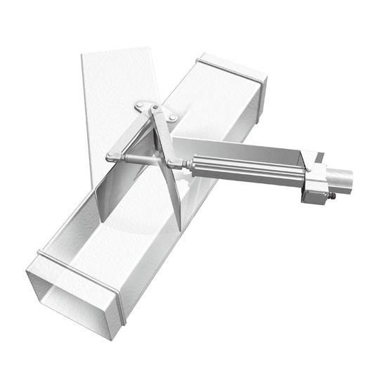
4 Application Solution TSUBAKI E&M Power Cylinders were born over 40 years ago, and have been used across a variety of industries by a wide range of customers. By taking advantage of our accumulated experience, we have continued to develop new products as well as upgrade technologies, and proactively address environmental issues to create our present series. We will continue to create products which are customer-friendly, taking the environment into consideration. For pusher/roller conveyor 3
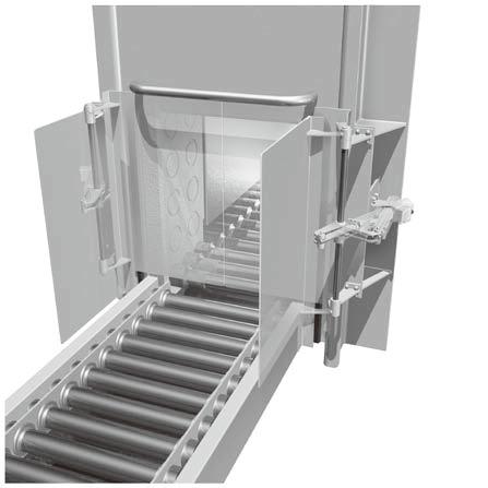
5 For heat treatment furnace/door opening and closing LCD TVs For lifters/pin insertion to fix For CT scanning/bed elevation For machine tools/door opening and closing 4
6 Power Cylinder 5
7 6


8 Power Cylinder
9
10 Power Cylinder Power Cylinder capacity range TSUBAKI E&M Power Cylinders can be used across a wide range of thrusts and speeds. Refer to the image diagram below and select the optimum model from the basic specifications list on pages 7 and 8. T series AC power source, large thrust Thrust Eco series servo type For servomotor F series DC power source, small and medium thrust Mini series Single-phase, 3-phase power source G series AC power source, medium thrust Eco series CDS type AC power source, for press contact stopping Speed 9


11 Power Cylinder Power Cylinder Eco series 10


12 Power Cylinder Eco Series Selection of each company s servomotors is facilitated. 11


13 Servo Type Expanded model Power Cylinder For low-speed uses, the motor capacity can be reduced in combination with our precision planetary reducer PAT-B. 12


14 13
15 Power Cylinder 14


16 15
17 LPES 1500 R 5 T 10 G5L A SUJ Power Cylinder 16
18 17
19 Power Cylinder 18

20 19
21 Power Cylinder 20
22 21
23 Power Cylinder 22
24 23
25 Power Cylinder 24
26 25
27 Power Cylinder 26
28 27
29 Power Cylinder 28
30 29
31 Power Cylinder 30
32 31
33 Power Cylinder 32
34 33
35 34
36
37 Power Cylinder 36


38 37


39 Power Cylinder 38


40 39


41 Power Cylinder 40
42 N 41
43 42 Power Cylinder


44 43
45 LPE 100 L K 5 MSJ Power Cylinder N 44
46 O O 45
47 Power Cylinder 46

48 Substitution for pneumatic cylinders Substitution for other companies electric cylinders 47


49 Substitution for pneumatic cylinders Power Cylinder Substitution for pneumatic cylinders Substitution for pneumatic cylinders 48


50 Substitution for hydraulic cylinders Substitution for pneumatic cylinders 49


51 Substitution for pneumatic cylinders Power Cylinder Substitution for hydraulic cylinders Substitution for pneumatic cylinders 50
52 51

 is standard.")
53 Power Cylinder F series Power Cylinder Eco series Small thrust type Power Cylinder, driven by DC (Battery) power source. AC power source is also available with AC adaptor (Option). Optimum for outdoor use, such as agricultural machine, multistory car parking. Light weight, small type Compact design where the operating part and the motor part are right angle. Effective utilization of installation space The hole of the clevis fitting is made in 2 directions at right angles to each other, the installation method can be selected from 4 directions so that it does not interfere with machine, etc. Versatile power source The DC power source type (12V DC, 24V DC) is standard. By using the AC adapter (sold separately), it can also be used with an AC power source. (LPF010, 020, 040 types) Wide variety of options Various options are available in comparison to the conventional type. Stroke adjustment external limit switch Bellows Position detection unit (internal limit switch, potentiometer) Overload detection unit Inquiry Form Mini series Multi series T series G series F series 52
54 Model No. designation LP F 040 L 2.0 V K2J Power Cylinder Thrust Nominal stroke Voltage code Options F series O O O O O O O Speed * The above is an indication example. * The speed is determined for each thrust. * Arrange the optional codes in the above specified order. Standard model list O Note) 1. In the case of 24V DC, V is attached at the end of the model number. 2. The numerical value in parentheses is an electric current value at the time of 24V DC. 3. Use a power source with a sufficient capacity in consideration of the locked rotor current. Motor specifications Standard use environment Ambient temperature Relative humidity Shock resistance value Installation altitude Atmosphere 1) If used below the freezing point, the characteristics of the cylinder (current value, speed) may change from the influence of grease. 2) Cylinders with bellows are recommended in an excessively dusty location. 3) All models are totally enclosed structures so that they can be used normally outdoors, however, when exposed to constant adverse conditions such as water, steam and snow accumulation, an appropriate cover is required. When using at 40 or higher, always protect with a heat insulating cover, etc. Never use in a flammable atmosphere. Otherwise it may cause an explosion and fire. In addition, avoid using in a location where vibration or shock exceeding 1G is applied. For use in a misty atmosphere, contact us. 53
55 Structure Power Cylinder Eco series Inquiry Form Mini series Multi series T series G series F series 54
56 Selection Operating conditions required for selection 1. Used machine and application 3. Strokemm 5. Frequency of operation, number of start/min. 2. Thrust or loadn f 4. Speedmm/s 6. Power voltage, frequency Selecting procedures 1. Select a suitable model number based on the thrust or load N {f }, stroke mm, speed mm/s. 2. Use the cylinder at an allowable operating frequency 2 times/min., allowable duty factor: 25%ED (5 minute basis), as for the frequency of operation. The Working time rate is a ratio of the operating time per 5 minutes on a 5-minute basis. Duration of life as a guide Duration of life is 15,000 reciprocations, as a guide. * Select a power cylinder of a sufficient thrust, allowing for a safety factor so that the loads used (static and dynamic) do not exceed the rated thrust. Characteristics graph 12V DC power source 24V DC power source O O O O O O Note) The graphs show standard values (12V/24V DC power source, ambient temperature 20 C). The speed and the current value vary depending on conditions of power source and ambient temperatures, etc
57 12V DC power source 24V DC power source Power Cylinder O O Eco series O O O O O O Inquiry Form Mini series Multi series T series G series F series Note) The graphs show standard values (12V/24V DC power source, ambient temperature 20 C). The speed and the current value vary depending on conditions of power source and ambient temperatures, etc
58 Dimensions Table Options Note) No limit switch for stroke adjustment is attached to the model of 50 mm stroke. The above-mentioned XA dimensions will not change even after attaching an external limit switch for stroke adjustment and bellows. The mechanical stroke preset value is 60mm or more. However, note that it does not include the coasting distance. O O Note) V is attached at the end of the model number for 24V DC. Model Circuit configuration Power rating Connection 29 57
59 Dimensions Table Options Note) No limit switch for stroke adjustment is attached to the model of 50 mm stroke. The above-mentioned XA dimensions will not change even after attaching an external limit switch for stroke adjustment and bellows. The mechanical stroke preset value is 60mm or more. However, note that it does not include the coasting distance. O Note) V is attached at the end of the model number for 24V DC. O Power Cylinder Eco series Inquiry Form Mini series Multi series T series G series F series 58 30
60 Position Detection unit Cabtire cable 0.5mm 2 x 6C length 500mm (internal limit switch) 0.5mm 2 x 3C length 500mm (potentiometer) For connection, see the position detecting device specifications on page 60. Note) Note that a position detecting unit cannot be manufactured for LPF600. Cabtire cable 0.5mm 2 x 6C length 500mm (internal limit switch) 0.5mm 2 x 3C length 500mm (potentiometer) For connection, see the position detecting device specifications on page 60. Internal structure For the position detecting unit, the following 2 types of position detecting devices can be built in as requested. Internal limit switch for position detection Potentiometer Note) An internal limit switch for position detection and a potentiometer cannot be used together
61 Position detecting device specifications Internal limit switch for position detection Use this LS when an external limit switch cannot be attached for reasons of installation space, or when the atmosphere is an adverse environment (with litter, dust, corrosion, etc.). When attaching 2 positions: Option code K2 Note) Up to 2 internal limit switches can be built in. (A position detecting device with 4 internal LS cannot be manufactured) Setting of limit switch Operate the power cylinder individually before installing to the machine and check the rotation direction of the LS cam. Install the power cylinder to the machine, and move the rod to a desired position to stop or to a position to detect the position. Rotate the LS cam and tighten the hexagon socket set screw and fix it at the position where the microswitch acts. At this point, based on the previously checked rotating direction, set the LS at the front side considering the cylinder coasting amount. Potentiometer This is a variable resistor to output electrical signals according to the stroke amount of the cylinder. Use it together with a print board and a stroke indication meter. The resistance value according to the model is already adjusted at the time of shipment. The potentiometer is set to work within the effective angle. Note that if the rod is rotated before installation, a phase with stroke will shift. <Cautions> * Note that LPF600 type with a position detecting unit is not available. * When an internal limit switch for position detection and a potentiometer are attached, the torque limiter mechanism is removed to prevent deviation in the preset values. Do not apply any load of the rated thrust or more to the cylinder during installation and operation of the cylinder. It may cause burnout of the motor. And do not hit the cylinder on the stroke end. It may cause the rod to get caught or burnout the motor. Control optional Overload detection unit Applicable for LPF010, LPF020, LPF040 AC adapter Necessary for protection against instantaneous overload and for press contact stop. Applicable for LPF010, LPF020, LPF040 Note) Check the cautions on page 62 when using an AC adapter. * For LPF100 through 600, the overload detection unit is a special type. * AC adaptor for LPF100 to 600 is not available. * As for LPF100 to 600, a special type with an AC motor is manufactured. Model Model number Power source Rated current Overload Load current protection function Start time Shock time Operation specifications Ambient temperature Ambient humidity Structure Mass O * No signal is output at time of overload. Circuit configuration Electrical rating Connection Model Total resistance Power rating Dielectric strength Effective electrical angle Effective mechanical angle Connection Model number Applicable motor Power source Rated current Overload protection function Load current Start time Shock time Operation specifications Ambient temperature Ambient humidity Structure Mass O * The overload protection function is built in the AC adapter. Power Cylinder Eco series Inquiry Form Mini series Multi series T series G series F series 60 32
 (Operation power: 200/220V 50/60Hz) The voltage signal from the potentiometer of the")
 and (-). Replace the terminals 1 and 2 on the print board to make the indication meter 100% when the stroke is minimum.")

62 Control option (for potentiometer) Stroke indication meter Stroke is indicated by % according to the signal from the print board. Model number Class Appearance Scale specifications Print board Model number (Operation power: 100/110V 50/60Hz) (Operation power: 200/220V 50/60Hz) The voltage signal from the potentiometer of the position detecting unit of the Power Cylinder F series is converted to a current value. Adjust the meter with the adjustment dial on the print board. Do not make a mistake with the stroke indication meter (+) and (-). Replace the terminals 1 and 2 on the print board to make the indication meter 100% when the stroke is minimum. Meter relay (the print board is the same as the print board of the stroke indication meter.) Used for simple adjustment of stroke on the operation panel. Iron panel is standard. Contact TEM when installing an aluminum panel. Model number Class Appearance Scale Power source Input Output contact structure Contact capacity <Relay operation> (In the case of b contact) Wiring is the same as the stroke indication meter, however, power supply is separately required for the meter relay. Supply from the operation power source, etc. As for the output contact, it is easy to connect the b contact serially to the b contact of the stroke adjustment LS, etc
63 Wire connection diagram * CAUTION LS11: Extend stroke adjustment external LS LS12: Retract stroke adjustment external LS (1) This diagram shows a single-acting circuit. When using in an inching circuit, remove the wire connections between N1 and N2, N3 and N4, and short-circuit the PBS. (2) A portion indicate a supply range of the power cylinder. Provide others than the portion on your side. (Stroke adjustment external LS is our option.) (3) Recommended breakers for LPF100H through LPF600L For 12V DC: NF32-SW 30A 250V DC (Mitsubishi Electric) or equivalent For 24V DC: NF32-SW 15A 250V DC (Mitsubishi Electric) or equivalent (4) Thermal relays for LPF100H through LPF600L For 12V DC: TH-N20 (Mitsubishi Electric) or equivalent For 24V DC: TH-N12 (Mitsubishi Electric) or equivalent Use drive relays (MF, MR) with the following capacities. * Drive relays for LPF100H through 600L are also available from us. Contact us. Use fuses with the following capacities as a guide. Be careful of the wire length (between motor and DC power source) and wire diameter in order to prevent voltage drop. Voltage drop may reduce the predetermined performance. Power Cylinder Eco series Overload detection unit (used for LPF010 through LPF040) * CAUTION When the overload detection has tripped, it is necessary to turn OFF the operation signal F or R once. If it is not turned OFF (not reset), a state that voltage is not output to the motor will be held. (Common to AC adaptor) (In the case of jogging operation, it is reset as the contact is opened when the push button is released (F or R is turned OFF).) AC adaptor wire connection diagram (used for LPF010 through LPF040) LS11: Extend stroke adjustment external LS LS12: Retract stroke adjustment external LS (1) This diagram shows a single-acting circuit. When using in an inching circuit, remove wire connections between N1, N2, N3 and N4. (2) A portion indicate a supply range of the power cylinder and AC adaptor. Provide others than the portion on your side. (Stroke adjustment external LS is our option.) (3) For relays of CF1, CF2, CR1 and CR2, OMRON relay MY or equivalent is recommended. (4) If the power source is 100V AC, connect the power to the dotted line part (100V terminal). * CAUTION 1. Securely separate contacts of the relays CF2, CR2 connected to the operation signals F, R on the AC adaptor from the AC circuit (200V class, 400V class) for use. If the AC circuit is built in the same relay, arc is generated between contacts due to surge, and the AC adaptor may be broken. 2. If a surge intrudes from the power line, connect a surge killer to the power terminal as a surge countermeasure. Surge killers which we recommend are 100V terminal ENC221D*, 200V terminal ENC471D*(Fuji Electric). For details on surge countermeasures, contact TEM. Inquiry Form Mini series Multi series T series G series F series 62 34
64 WARNING Cautions for installation Use pins to connect the power cylinder with the equipment. Align phases of pins (clevis fitting pin and end fitting pin). Apply grease into the clevis fitting holes and end fitting holes, and pins before installation. Pay attention so as not to apply a lateral load on the power cylinder when installing. All models are totally enclosed structures so that they can be used normally outdoors, however, under adverse conditions exposed to constant water and steam etc., and snow accumulation, although they are an outdoors type, an appropriate cover is required. The power cylinder can generally be used in a range of -5 to 40, although it varies depending on the use conditions. When using at 40 or higher, always protect with a heat insulating cover, etc. Never use in a flammable atmosphere, otherwise it may cause an explosion and fire. In addition, avoid using it in a location where vibration or shock exceeding 1G is applied. The main body is of outdoor specifications however, carry out proper waterproofing treatment on the motor lead wire terminal with waterproofing connectors etc. Cautions for use Speed and current value change with an increase/decrease in load. For details, refer to the characteristics diagram. Linkage operation cannot be performed due to characteristics of the motor. When rectifying alternating current to use without using battery power, make sure to smoothen the current and provide a DC power supply with a capacity so that the voltage does not drop. It greatly affects performance of the power cylinder and the duration of the life of the brush. (As an option, an AC adaptor for an output voltage of 24V is available. This adaptor supports LPF010 to 040 only. For LPF 100 or larger, contact us separately. When using with other than commercial power supply, check that power voltage variation is within a range of ±10 and the power supply is an alternating current power supply without strain.) When using an AC adaptor, use a power cylinder of 24V DC specifications. 12V DC specifications are within a voltage range from 10 to 14V, and 24V DC specifications are within a voltage range from 20 to 28V. Note that the speed varies if the voltage varies due to the characteristics of the DC motor. No overload detection mechanism is built in the LPF series. When detecting an overload, commonly use the overload detection unit as an option. For LPF010 to 040, combine with the overload detection unit to allow for press stopping. (For LPF100 to 600, an overload detection unit of special model can be manufactured, however, press stopping cannot be performed.) When press stopping is performed, allow the equipment to have a sufficient strength (rated thrust x 300%) When not using the overload detection unit, never perform press stopping, and use within the stroke range otherwise the power cylinder may be damaged. A model of stroke 50mm cannot be equipped with a stroke adjustment external LS. The mechanical stroke adjusting range of the stroke adjustment external LS is 60mm or more. However, note that it does not include a coasting distance. If coasting becomes a problem, provide a dynamic brake circuit separately. Our overload detection unit and AC adapter are provided with a dynamic brake circuit. Anti-rotation is required because the rod of the power cylinder generates a rotating force with thrust. The rotating force of the rod is as follows. Cautions for maintenance and inspection The operating portion and reduction portion are filled with grease, therefore, it is not necessary for them to be greased. The duration of life is reciprocations as a guide. Structurally, repairs and parts supply are not available. If the above reference life is exceeded, replace the main body with a new one


65 F series plus Plus Ver.1 with AC motor LPF 100 H 1.0 X - TK Power Cylinder Eco series Plus Ver.2 with ball clutch type overload protection device LPF 100 H TK Inquiry Form Mini series Multi series T series G series F series 64 36


66 F series Plus Plus Ver.3A Parallel (folded type) LPF 100 M K TK 37 65

67 Power Cylinder G series Power Cylinder Eco series Power cylinder in intermediate thrust zone which can be used with AC power supply. This can be used across a wide range of applications such as steel, food and multistory car parking for general industry. Wide variation Basic 630 models and approximately 9000 models including option are standardized. LPGA: Simple and basic economical type LPGB: Built-in slip overload protection mechanism type LPGC: Built-in thrust detection, press stop mechanism type Screw type selectable according to use Trapezoidal screw excellent in cost performance Best-suited for low-speed, low-frequency use High-efficiency, long-life ball screw Best-suited for high-speed, high-frequency use Quick delivery of special motor (For details, refer to page 120.) Heat resistance class F and class H are supported. Different voltage specifications (Overseas voltages are supported.) Inverter specifications Global specifications (CE-compliant, UL-compliant and CCC-compliant) Explosion-proof specifications Quiet operation Noise at the start and stop has been greatly reduced by drive of the motor with a quiet DC brake. Excellent speed stability This power cylinder is basically structured so that the screw shaft is rotated by the induction motor and the nut (rod) is extend and retract, allowing for a stable speed run which is hardly affected by load variation. Inquiry Form Mini series Multi series T series G series F series 66 38
68 Model No. designation LP GC 300 L T 5 V T1 K2PJ Power Cylinder Thrust Speed Motor spec symbol Options G series N N N N *1 Only parallel type is available. Shape of main body Nominal stroke * The above shows display examples. Voltage symbol *3 Anti-rotation mechanism for LPGC type is not available. *4 The clevis fitting cannot be combined with K2, K4, P or R. Trapezoidal screw type standard model list O O *1. Only parallel type is available. *2. LPGC type is not available. Ball screw type standard model list O O *1 Only parallel type is available. *2 LPGC type is not available. *3. Cannot be used for press contact stopping at the U speed. 67
69 Motor specifications Painting color Standards use environment Power Cylinder Structure Eco series Inquiry Form Mini series Multi series T series G series F series 68
70 Classification of usage according to type (protection device) The power cylinder G series includes the following three types. Each of these can be selected so that optimum functions can be fully exerted depending on application. The three types of power cylinders have the same performances (thrust, speed, stroke). This type has a stop function with a brake only. Note that use exceeding the nominal stroke may result in breakage. When using this type, sensor for stroke regulation must be installed or optional external limit switch for stroke adjustment must be used. (The other two types similarly require a sensor for stroke adjustment.) When detecting abnormalities, combination with an electric protection device is recommended. A shock relay and shock monitor are available as electric protection devices. When any overload phenomena occurs and the set thrust is exceeded, the built-in torque limiter slips to exert the protecting function. However, long time slip generates heat on the motor, resulting in burnout, or reduces the transmissible torque, resulting in malfunction of the cylinder. Therefore, usage in combination with our shock relay is recommended. A type with a thrust detecting mechanism in combination with a pre-loaded spring and a limit switch. This mechanism exerts an effect in the following cases. When press (pull) and stop are performed. When an electric signal is required at overload. When an overload is possibly applied from the load side during stoppage. The built-in spring absorbs deflection impact load for impact within the rating. * Cannot be used for press contact stopping at the mechanical stroke end. [Thrust detecting mechanism] When extending At normal condition When the cylinder is overloaded while extending When the cylinder stops within the XA dimension at the time of extending When a pressing force is attempted to be maintained even after stop When retracting When the cylinder is overloaded during retracting When the cylinder stops within the XA dimension at the time of retracting When a pressing force is attempted to be maintained even after stop Preset load for protection device Preset loads for protection devices of the GB type and GC type are as follows. The protection device does not work at the start for opening/closing of the damper or the hopper gate, normal reverse, inclination and elevation, however, when load inertia is large due to horizontal movement of the carriage, the protection device works to impair smooth operation at the start. When load inertia exceeds values shown in the table below, take countermeasures such as slow start operation by the inverter, etc. <Operation preset load for protection device> GB (with a torque limiter): 150% to 200% of rated thrust GC (with a thrust detecting mechanism): 140% to 200% of rated thrust * Use the above values as a guide. Cautions for use When installing rotary encoder or potentiometer For the LPGC type, a spring mechanism is built in the operating part. The spring slightly deflects at press (pull) and stop, or when an overload occurs, the signal amount deviates by the deflection. For LPGB type, even if the safety device is tripped, the signal amount does not deviate. However, the LPGC type can be used at normal stroke operation. When there is a problem with movement of the rod even if overload is applied from the load side during stop For the LPGC type, a spring mechanism is built in the operating part, therefore, when a large load is applied, the spring deflects and the rod moves by the deflection. When the load is eliminated, the rod returns to the original position. When using with press (pull) and stop, strength of the mating device shall be 250% of the rated thrust or more. When the LPGC type is used, the time lag should be 0.03s or less
71 Selection 1 Conditions of use required for selection 1. Machine to be used and application 2. Thrust or loadn f 3. Strokemm Selection procedures Guide for life Selection 2 4. Speedmm/s 5. Frequency of operation, number of starts/min. 6. Power source voltage, frequency 7. Type of load of machine used 8. Environment of use 9. Hours of operation a day and annual operating days 1. Select the suitable model number from the standard model list (page 67) based on thrust, load N{ }, speed (mm/s), and stroke (mm). 2. Determine the shape (straight or parallel) of the main body suitable for the installing condition, necessity of protection device and option from the machine used and use conditions. 3. Check that the frequency of operation and the working time rate are within the allowable values of the cylinder. Frequency of operation and the working time rate Allowable start cycle Allowable duty factor (%ED) 10 cycles/min. or less 25 The working time rate is a ratio of the operating time per 10 minutes on a 10-minute basis. <Expected traveling distance of trapezoidal screw type> 25km in cylinder (nut) traveling distance <Expected traveling distance of ball screw type> The life of a ball screw is determined by flaking of the rolling surface caused by its fatigue. Check the rough life with this chart of expected traveling distance. However, in the case of great impact or in the case where lubrication or maintenance is not performed properly, the expected traveling distance becomes substantially short. Expected traveling distance (km) = actual load stroke (m) frequency of use (times/day) number of operating days 10-3 expected number of years The chart on the right-hand side is based on L10 life. L10 life expresses in traveling distance a life that can be reached by 90% or more of all ball screws. If you select a power cylinder based on the life, select model No. from this chart. If the load greatly fluctuates in the middle of stroke, calculate the equivalent load (PM) by the equation on the right-hand side. Brake holding force A load holding force while the power cylinder stops is exerted more than the rated thrust, therefore, it can be used for holding a load of the rated thrust. This holding force is generated by braking operation of the brake motor. The brake is of a spring braking type that always performs braking operation by a spring force during stop, and the brake torque has a holding force of 150% or more of the motor rated torque. The expected life of the brake is 2,000,000 times. However, gap adjustment is required. * When selecting the H, U speed, refer to the cautions for selecting on page 84. * Select a power cylinder of a sufficient thrust, allowing for a safety rate so that the loads used (static and dynamic) do not exceed the rated thrust. Refer to the following cylinder characteristics data to check that the cylinder is suitable for the application. <Coasting distance and stop accuracy> Coasting amount and stop accuracy vary depending on the operation speed and load. When you attempt to correctly position, cylinders with low operation speed are recommended. Set the limit switch in consideration of the coasting distance. Refer to the cautions for selecting on page 84. Reference values of the coasting distance and stop accuracy are shown in the following table. Unit: mm * The values in the above table slightly vary depending on the models. * Coasting distance: This indicates a distance from a time when the limit switch or the stop button is operated until the cylinder stops. This coasting distance varies depending on how a load is applied and the operation circuit. * Stop accuracy: This indicates a variation in the stop position when stop is repeated. The above table takes ±25% of time lag of the relay and the brake into consideration. * An anti-rod rotation mechanism is required. Power Cylinder Eco series Inquiry Form Mini series Multi series T series G series F series 70 42
72 Dimensions Table Straight type Note) 1. The mechanical stroke includes a margin of 3 to 8 mm of the nominal stroke on both sides. 2. For U speed, only 070 and 100 are applied. Unit: mm O Options Mass: 3.5kg/set Note) Shipped as attached to the main body. The XA dimensions are the same as the standard U-type end fitting. Note) Apply grease to the trunnion pin and into the trunnion hole for installation. * Dimensions with no tolerance described have general tolerance, and their sizes become larger by approximately 2 to 5mm from the described dimensions. When designing the machine, take margins into consideration
73 MEMO Inquiry Form Mini series Multi series T series G series F series Power Cylinder Eco series 72 44
74 Dimensions Table Parallel type Note) 1. The mechanical stroke includes a margin of 3 to 8 mm of the nominal stroke on both sides. 2. For U speed, only 070 and 100 are applied. Options Unit: mm O Note) Apply grease to the trunnion pin and into the trunnion hole for installation. Mass: 3.5kg/set Note) Shipped as attached to the main body. The XA dimensions are the same as the standard U-type end fitting. Mass : 1.7kg * Dimensions with no tolerance described have general tolerance, and their sizes become larger by approximately 2 to 5mm from the described dimensions. When designing the machine, take margins into consideration
75 MEMO Inquiry Form Mini series Multi series T series G series F series Power Cylinder Eco series 74 46
76 Position detecting unit The following three types of the position detecting device can be built in the position detecting unit at your request. Mass : 7.3kg Internal structure Note) This unit cannot be mounted with a clevis fitting. Mount this unit with a trunnion fitting. Wire connection into position detecting unit Use terminals provided in the unit to connect to the internal limit switch, potentiometer and rotary encoder. COM for the internal limit switch is common. (internally wire-connected) Use shield wire for wire-connection to the rotary encoder. 1. Position detecting internal LS (with two or four pieces) Use this LS when the external LS cannot be installed due to the installation space or when performing operation in combination with the potentiometer or the rotary encoder. With two pieces: Optional symbol K2 Arrangement of LS1 and LS2 in the above figure. With four pieces: Optional symbol K4 Arrangement of all of LS1 through 4 in the above figure. Model Circuit configuration Electric rating Connection <Setting of LS> First, before installing a power cylinder to the equipment, operate the cylinder in a single unit to check the rotating direction of the LS cam. Intall the equipment to the power cylinder, stop the power cylinder, or, move it to a position where you would like to have it be detected. Then, rotate the LS cam, and tighten the hexagon socket head set screw to fix at a position where the micro switch operates. At this time, estimate a coasting amount of the power cylinder depending on the pre-checked rotating direction
77 Position detecting unit 2. Potentiometer This is a variable resistor to output electric signals depending on the stroke amount of the power cylinder. Use this unit in combination with TSUBAKI TC unit, or print board and stroke indication meter. Resistance values according to the model have been adjusted before shipment. Separately request preset values according to the model as they are described in the position detecting unit specification drawing. Pay strict attention to handling because correspondence between the stroke position and the resistance value will deviate by rotating the rod of the power cylinder. Model Manufacturer Total resistance Rated power Dielectric strength Effective electric angle Effective mechanical angle Connection Power Cylinder 3. Rotary encoder Model Manufacturer Output pulse number Output waveform Output voltage Power supply Output connection Signal 1 Signal 2 Figures in parentheses indicate terminal No. Output waveform Signal Z +5V to 24V 0V Case The output signal of the standard specification is of an incremental type, however, an absolute type is also available. The output type in standard specifications is an open collector. If voltage output type is required, see (Note 1) below. If the specification of line driver output is required, contact us. Note 1) Due to the open collector output, output signals are obtained when the pull-up resistor is connected. Signal 1 and signal 2 are output voltages of H (power supply voltage 1)V or more and L 1V or less. For the Z-phase, negative logic applies. <Reference resistance values> 5V: 220Ω, 12V: 470Ω, 24V: 1kΩ Output circuit * Best suited to controlling the stroke by a sequencer or programmable controller, etc. More accurate positioning control is possible in combination with motor speed control by an inverter, etc. The standard products incorporate an incremental type encoder. The rotary encoder has been set to output 20 pulses per stroke of 1mm. It is possible to set an accurate home position of the machine in combination with a limit switch because home position output is read out every 600 pulses. Do not apply vibration or impact to the rotary encoder because it is precision equipment. Use shield wire for wiring to the rotary encoder. As a guide for the distance between the rotary encoder and control panel, a collector current of 20mA should be able to be transmitted approximately 50m (12V pull-up). For distances other than the above, consult with us. Eco series Inquiry Form Mini series Multi series T series G series F series 76 48
78 Control option For potentiometer This meter indicates a stroke in % by a signal from the print board. Model Grade Appearance Scale specification * A separate printed board is also required. This printed board converts voltage signals from the potentiometer in the position detecting unit of the power cylinder G series into current signals. Adjust the meter with an ADJUST volume on the print board. Do not make a mistake with the stroke indication meter + and -. Replace the terminals 1 and 2 on the print board to set the indication meter to 100% when the stroke is MIN. Model LPCO-D1 (Operation power 100/110V 50/60Hz) LPCO-D2 (Operation power 200/220V 50/60Hz) This controller converts voltage signals from the potentiometer in the position detecting unit of the power cylinder G series into digital signals, and performs indication and stroke control. This controller incorporates a scaling function, and can indicate real strokes or extension (%). This R controller can be directly connected to the potentiometer. Model Total resistance value of input potentiometer Indication Appearance Comparison output Comparison preset value Comparison output contact capacity Output contact configuration Power supply Used for simple adjustment of stroke on the operation panel. Iron panel attachment is standard. Contact us separately when installing an aluminum panel. Note) For using 4 20mA output, designate as for 4 20mA output. Model Grade Appearance Scale Power supply Input Output contact configuration Contact capacity * A separate printed board is also required. The power cylinder body is equipped with a potentiometer. Since the phase of the stroke will deviate if the rod is rotated before installation, cylinders with a stroke adjusting LS are recommended. Pre-set the minimum and maximum strokes to be used with the stroke adjusting LS, and then use the meter relay. (The described specifications and dimensions may be subject to change due to circumstances.) 77
 Wire connection is the same as that for the stroke indication meter, however, it is necessary to separately feed power to the meter relay.")

79 Control option <Printed board> This is the same as the printed board for the stroke indication meter. <Relay operation> (In the case of b contact) Wire connection is the same as that for the stroke indication meter, however, it is necessary to separately feed power to the meter relay. It is easy to connect the b contact as an output contact to the b contact for the stroke adjusting LS in series. Power Cylinder Eco series Shock relay Our highly reliable shock relay is recommended as an electric safety device for the GB type power cylinder. For details, refer to the TSUBAKI E&M SAFCON overload protection devices and control devices catalogue. Shock relay TSBSA series (Economy, automatic reset type) Shock relay TSBSS series (Economy, self-holding type) Shock relay TSBED series (Digital indication, self-holding/automatic reset type) Inquiry Form Mini series Multi series T series G series F series 78
80 Wire connection Wire connection for brake motor (motor with DC brake) Brake internal wiring 200V class 400V class Power side Power side Brake external wiring 200V class 400V class Power side Note) 1. When AC external wiring in the three-phase 400V class motor, make sure to insulate the wire from the intermediate tap. In this case, input power supply to the power module requires 200 to 220V. If no power of 200 to 220V is supplied, decrease the voltage to 200 to 220V by a transformer. If a voltage of 230V or more is directly input to the power module, the brake and the power module may burn out. The capacity of the transformer shall be 90VA or more (0.1 to 0.4kW), and check that there is no voltage drop. Use an MCB with a contact capacity of 250V AC, 7A or more. The power module includes a surge absorbing protection element. Add a protection element for the contact in each part if necessary. 2. Do not put a relay contact on the output side of the standard power module (between the power module and brake coil). (Do not perform DC external wiring.) 3. By the above connection, the rod retracts in a straight type, and the rod extends in a parallel type. * Crimp contact bolt: M4 * For the other details, refer to the Operation Manual. Limit switch specification Model Circuit configuration Electric rating Connection Motor current value, Brake current value Note) 1. The above values are rated current values of the motor and brake. The numerical value in parentheses is a start current value of the motor. 2. The rated current values and start current values do not include brake current values. 3. A DC brake is used as a brake. The upper stage of the brake current value indicates a value on the primary side of the power module, and the lower stage indicates a value on the secondary side. 4. The above values are references because the rated current values for the power cylinder vary depending on the operating conditions. 5. For AC internal wiring of the 400V class, the voltage is converted to 200V through the motor intermediate tap to be input. For AC external wiring, decrease the voltage to 200 to 220V by a transformer. The capacity of the transformer shall be 90VA or more
81 Reference circuit 200V Class GA type brake internal wiring reference circuit LS01: Extend stroke adjusting external limit switch LS02: Retract stroke adjusting external limit switch (1) This diagram shows a single-acting circuit. When using in an inching circuit, remove the wire connection between N1 and N2, N3 and N4, and short-circuit the PBS. (2) If the power voltage for the motor is different from the control voltage, put a transformer into a portion in the diagram. (3) When AC external wiring the brake, remove the short piece on the terminal block and apply a normal power voltage (200 to 220V) to B1 and B2 from the outside. * For wire connection when an inverter is used, refer to page 114. Power Cylinder Eco series 400V Class GA type brake internal wiring reference circuit LS01: Extend stroke adjusting external limit switch LS02: Retract stroke adjusting external limit switch (1) This diagram shows a single-acting circuit. When using in an inching circuit, remove the wire connection between N1 and N2, N3 and N4, and short-circuit the PBS. (2) If the power voltage for the motor is different from the control voltage, put a transformer into a portion in the diagram. (3) When AC external wiring the brake, remove the wire connected to the terminal block from the motor intermediate tap and insulate it. Apply a normal power voltage (200 to 220V) to B1 and B2 (primary side of the module). If there is no power of 200V, decrease the voltage to 200V by a transformer. The capacity of the transformer shall be 90VA or more (0.1 to 0.4KW), and check that there is no voltage drop. Use a contact capacity of 250V AC, 7A or more. * For wire connection when an inverter is used, refer to page 114. (1) This diagram shows an example of kW brake internal wiring circuit for linkage of two in inching motion. (2) If the power supply voltage for the motor is different from the control voltage, put a transformer in the section in the diagram. (3) Lead wires B1 and B2 for the brakes are connected to U and W on the motor terminal block by using short pieces. (4) For using the brakes by external wiring, remove the short pieces, and externally apply not inverter output but normal power supply voltage to B1 and B2. Inquiry Form Mini series Multi series T series G series F series 80 52
82 Installation Installation direction Either horizontal, vertical and inclined directions are allowed. Installation method For installation of the main body, use a trunnion mount or clevis mount (parallel only). Apply grease to the trunnion pins and bracket holes for mounting. Install the end part with a U-type or -type end fitting. Maintenance Greasing on screw Use the screw as it is because it has been applied with greased in advance. Refill grease with reference to Table 1-2 as a guide. To apply grease to the screw, remove the greasing port bolt on the outer cylinder and advance the rod in the full stroke and apply grease to the outer circumference of the screw with a grease gun, and then reciprocate the rod within the stroke to be used. Repeat this operation a few times. Trunnion mount Clevis mount WARNING Mannual operation When manually adjusting the stroke, rotate the manual shaft on the motor opposite load side with the manual handle after releasing the brake. For how to release the brake, refer to the Operation Manual. The manual handle is attached to the product. WARNING When a load is applied to the rod, remove the load before releasing the brake. For the amount of movement of the rod per one turn of the manual shaft, refer to the standard model list (page 67). Anti-rod rotation 1. Anti-rod rotation is required because a rotating force is generated on the rod with thrust. Generally, rotation can be mainly prevented by installing the rod end to a driven machine. 2. When operating with the end set free or installing pulleys to pull a rope, use a rod anti-rotation specification (option symbol M). Setting of stroke adjusting external LS 1. Take the coasting amount (page 70) into consideration to set adjustment of the limit switch. 2. When using the cylinder at the nominal stroke, set the limit switch so that the cylinder stops within the XA dimension in the Dimensions Table. 3. When synchronized operating two or more power cylinders, install a limit switch at the extend limit and retract limit on each cylinder to stop each cylinder. Avoid controlling all power cylinders with one limit switch because accumulated errors in stroke will occur. For the control circuit, see the example of circuit for linkage on page 80. Never insert your finger into the greasing port. If the cylinder operates with your finger inserted, your finger may be injured. Table 1 Recommended grease Screw shaft TSUBAKI E&M IDEMITSU KOSAN NIPPON GREASE EXXON MOBILE COSMO OIL LUBRICANTS SHOWA SHELL * The above greases are filled before shipment. Note) JWGS100G is separately sold in a container of 100g. (See page 262.) Table 2 Lubrication cycle Traveling distance Operating frequency Note) The above values are for longer use, and do not indicate life. Greasing on Reduction part Grease has been applied on the tooth surfaces in advance, therefore, use the decelerating part as it is. Initial tooth surface application grease Planetary gear (straight type): Moly gear grease No. 1 (SUMICO LUBRICANT CO., LTD.) Helical gear (parallel type): Moly gear grease No. 1 (SUMICO LUBRICANT CO., LTD.) * Apply grease to the helical gear part (parallel type) approximately once one year
83 Adjustment of external limit switch and variation of mounting 1. Standard Mounting Form Straight Power Cylinder Parallel Eco series 2. Adjustment method The power cylinder G series has a margin of approximately 3 to 8mm of the nominal stroke on both sides which allows for mechanical stroke. The stroke to be used is within the nominal stroke, therefore, adjust the limit switch so that operation is made in this range. If the nominal stroke is exceeded, the striker protrudes from the LS guide rail. When adjusting the limit switches, adjust and fix the limit switches one by one so that the relative position between the LS guide rail and the cylinder body is not deviated. <Adjustment method> 1. Loosen the LS flange tightening bolt (A) and the guide rail tightening bolt (B). 2. Slide the flange to a position where you want it set. 3. Tighten the guide rail tightening bolt (B) beforehand. 4. Check that the guide rail and the LS rod are not twisted, and tighten the LS flange tightening bolt (A). 3. Mounting variations Mounting several pieces 4. Change in mounting work Example of normal and emergency use Different position Different direction For change in orientation and quantity, a separate Instruction Manual is available. Contact us. Either mounting direction is allowed, however, take the direction into consideration so that accumulation of dust or dirt the guide rail does not impair operation of the striker. Inquiry Form Mini series Multi series T series G series F series 82 54
84 Variation in direction and position of terminal box 1. Direction of motor terminal box The motor terminal box can be fixed in four directions shown in the following diagram. This direction can be easily changed by the customer. Be aware that if the lead wires are pulled or bent forcefully, the wires will be broken. Procedures to change are as follows. 1. Remove the lid of the terminal box. 2. Remove the two screws fixed to the terminal block. 3. Bring up the terminal block without removing the wire connection for the motor and the brake, and remove the four screws fixed to the terminal box. 4. Rotate the terminal box in the desired direction and re-fix it to the main body. 5. Install the terminal block again. Be aware that if the lead wires are trapped under the terminal block, the wires will be broken or an insulation failure will occur. 6. After connecting the power cable, install the lid, then the procedures are completed. When fixing the terminal box to the main body, check that the rubber packing is correctly sandwiched, then firmly tighten the four screws. 2. Position of motor terminal box The position of the motor terminal box can be rotated by every 90 degrees around the motor shaft as shown in the following diagram. However, this change must not be carried out by the customer. Specify the position when ordering the power cylinder
85 Cautions for selecting WARNING Anti-rod rotation is required because a rotating force is exerted on the rod with thrust. Rod rotating forces at the rated thrust are described in the model list. When operating with the end unconnected or when installing pulleys to pull rope, use an optional rod anti-rotation specification. When the cylinder operating stroke is short, a high speed type cylinder cannot be used because the operating time per one stroke becomes shorter and cannot be controlled. The following table shows the minimum necessary strokes when motor energization time is 0.5s. Refer to this table to determine the speed. Power Cylinder Eco series Cautions for installation Cautions for use Apply grease to the trunnion pin and the trunnion hole for trunnion mounting. Also, apply grease to the connecting pin of the end fitting and the connecting pin for clevis mounting. When the main body greatly swings by operation of the cylinder, consider using a sliding bearing or a rolling bearing for the connecting part. Cylinders whose trunnion hole is provided with sliding bearing are available as MTO. When the trunnion pin or connecting pin for the clevis or the end fitting is directed in the vertical direction (when the cylinder is laid horizontally), and the main body swings, take countermeasures for wear such as inserting a bearing member into the trunnion hole, the clevis fitting, or the side part of the end fitting. All models are totally enclosed structures so that they can be used normally outdoors, however, under adverse conditions exposed to constant water and steam etc., and snow accumulation, although they are an outdoors type, an appropriate cover is required. The power cylinder can generally be used in a range of -15 to 40, although it varies depending on the use conditions. When using at 40 or higher, always protect with a heat insulating cover, etc. Never use in a flammable atmosphere, otherwise it may cause an explosion and fire. In addition, avoid using it in a location where vibration or shock exceeding 1G is applied. For use in a misty atmosphere, consult with us. When using a cylinder of the cabtire cable lead wire specification outdoors, carry out waterproofing treatment sufficiently. Regulate both ends of the stroke by the limit switch. Select a type of option which allows the limit switch to be mounted on the power cylinder body. Use within the stroke range. If the stroke is exceeded, breakage may occur. As a high-speed type (U, H speed) of the power cylinder G series has a long coasting distance, the striker may override the limit switch. (The striker for the U-speed power cylinder overrides the limit switch at the rated lifted load.) For this reason, make sure to allow a limit signal to be self-held on the control circuit. Megger testing is prohibited for this cylinder. It may break the built-in power module. Remove the brake wiring for the terminal block when conducting megger testing of the external circuits. Adjustment of the limit switch for thrust detection of the GC type must not be carried out by the customer. The preset value for thrust detection may greatly change. Inquiry Form Mini series Multi series T series G series F series 84 56

![Slim & Simple Costeffective Safe To respond to voices of the power cylinder is troublesome when it comes to wiring! from customers, [simple wiring specifications] have been added to LPG series.](/docs-images/92/109001184/images/86-1.jpg "(Option) The power cylinder can be selected from two of Automatic detecting type and Centralized terminal box type with the keywords of simple, neat, reduction in wiring man-hours, and safety")
86 Easy wiring specifications This is a specification in which limit switches for thrust detection and external adjustment are wired by us before shipment. For details, request a leaflet. Expansion of models TSUBAKI E&M Power cylinder G series Plus Ver.2 Easy wiring specifications Power cylinder G series have become easier to use. Slim & Simple Costeffective Safe To respond to voices of the power cylinder is troublesome when it comes to wiring! from customers, [simple wiring specifications] have been added to LPG series. (Option) The power cylinder can be selected from two of Automatic detecting type and Centralized terminal box type with the keywords of simple, neat, reduction in wiring man-hours, and safety (automatic detecting type). In standard specifications Large number of wires and its complexity require wiring man-hours and cost at the relay box. Equipment may be damaged due to omission of wiring for the external limit switch for thrust detection and stroke adjustment. Power Cable Relay BOX Needs simplicity! Signal Cable Control Board By adoption of easy wiring specifications Automatic detecting type Pre-wired Advantages Signal Cable Slim and simple in appearance Cost reduction by pre-wired relay boxes Operates just by connecting the power cable to the terminal box Prevents damage from excessive torque and stroke caused by incomplete relay box wiring Power Cable Centralized terminal box type Control Board Pre-wired Signal Cable Power Cable Control Board 57 85


87 Power Cylinder T series Power Cylinder Eco series This is a power cylinder of a large thrust type which can be used with AC (alternating current). Power cylinder T series can be used across a wide range of applications such as steel, injection molding machines, liquid crystal and semiconductor device. This power cylinder can be used outdoors. (IP55) Two easy-to-select types T series have two types which are different in safety mechanisms from each other. The TB type incorporates a wet slip clutch. TC type is equipped with a thrust detecting limit switch. Wide variation A wide range of models are available as standard according to application, thrust and speed. Thrust can be selected in a range from 2.45kN{250kgf} to 313kN{32000kgf}, and speed can be selected in a range from 10mm/s to 120mm/s. For details, refer to the standard model list. Reliable operation All models adopt a highly efficient ball screw, quiet reduction part, and highly reliable brake motor. All series incorporate a highly reliable safety device which works effectively against overload. Abundance of options The stroke adjusting limit switch includes two types of the external type and internal type, and the stroke sensor includes two types of the potentiometer method and rotary encoder method. Control by a sequencer becomes simpler. For a stroke sensor with potentiometer, an option not only indicating stroke but also allowing for control by a meter relay is also available. Quick delivery of special motor (For details, refer to page 120.) Heat resistance class F and class H are supported. Different voltage specifications (Overseas voltages are supported.) Inverter specifications Global specifications (CE-compliant, UL-compliant and CCC-compliant) Explosion-proof specifications Inquiry Form Mini series Multi series T series G series F series 86 58
88 Model No. designation LP TB 1000 L 4 V T1 LPCJF Power cylinder Thrust Speed Motor Option Options T series N N N N N N N Nominal stroke *The above values are examples of indication. Voltage symbol *2 When four or more clevises are installed, indicate this to us separately. *3 The clevis fitting cannot be combined with K2, K4, P or R. *4 For LPT6000 and above, the -type end fitting is standard (no symbol). *5 The stroke is not changed. * The Trunnion fitting is not included in the body model number. Please separately specify a Trunnion model number. * Manual operating handles are also available. Standard model list N Note) The numerical value in parentheses on rated thrust is for the long stroke type. N (Rated thrust is 7.84kN) (Rated thrust is 15.7kN) (Rated thrust is 12.2kN) (Rated thrust is 33.3kN) DC brake Brake external wiring is available 1) The rated thrust is limited for the stroke marked with an*. 2) The speeds indicate a value at the motor synchronized rotating speed. 87
89 Motor specifications Model Output Number of poles Voltage Frequency Heat resistance class Time rating Protection method Painting color 1) 400/440V, different voltage specifications other than the above voltages are also available. 2) For motor current value and brake current value, refer to page 115. TSUBAKI olive gray (Munsell 5GY6/0.5 or approximate color) Standard use environment Outdoor type 1) Cylinders with bellows are recommended in an excessively dusty location. 2) Special painting is available for locations exposed to sea breezes and salt. Consult us. 3) All models are totally enclosed structures so that they can be used normally outdoors, however, under adverse conditions exposed to constant water and steam etc., and snow accumulation, although they are an outdoors type, an appropriate cover is required. When using at 40 or higher, always protect with a heat insulating cover, etc. Never use in a flammable atmosphere, otherwise it may cause an explosion and fire. In addition, avoid using it in a location where vibration or shock exceeding 1G is applied. For use in a misty atmosphere, contact us. Power Cylinder Structure TB type Eco series TC type Brake motor Reduction part Actuation part * The structure slightly varies depending on the model. This motor adopts a deenergization operation type (spring close type), and the brake is applied while the cylinder stops. This brake action holds load while the power cylinder stops and reduces coasting during stoppage, and serves the purpose of increasing stop accuracy. All of the brake motors adopt outdoor types. The reduction part adopts a combination of a helical gear on the high speed side and a spur gear on the low speed side. The lubrication method is grease bath type, and has a quiet operating specification. Furthermore, a manual handle shaft is provided, and the structure of the speed reducer facilitates operation at power failure and adjustment for installation. As options, various position detecting devices can be installed. The actuation part is provided with a ball screw and nut which converts a rotating force into linear motion. Further, external limit switches for stroke adjustment can be mounted. A high precision ball screw and nut have advantages such as high transmission efficiency, less wear, long life and easy lubrication. The external limit switches for stroke adjustment are structured to freely adjust the stroke and endure outdoor use. The bellows are excellent in weatherproofing, and the stroke does not change even if the bellows are mounted. The seal for the rod also endures outdoor use. Inquiry Form Mini series Multi series T series G series F series 88
90 Classification of usage for LPTB and LPTC types Both types of the power cylinders have the same basic functions (thrust, speed, stroke), however, each has its feature as regards the mechanism. Read the following to select the optimum type. TB type Wet slip clutch type (simple type) [Wet slip clutch] The screw shaft end of the reduction part incorporates a slip clutch which operates stably in grease as a safety device. Adoption of special lining exerts a protective function even at the time of overload or stroke overextension. * When overload is electrically detected, use in combination with our shock relay is recommended. TC type Thrust detecting mechanism type This type exerts its effect in the following cases. When performing press (pull) stop When requiring an electric signal at the time of overload When an overload is possibly applied from the load side during stop When an overload is impulsively applied, the incorporated spring absorbs the impact load. [Thrust detecting mechanism] This is a thrust detecting mechanism which combines two types of pre-loaded disc springs whose spring constants are different from each other and limit switches. The combined effect of these disc springs also allows for press and stop of the high speed type. (There is only one type for the 6000 type and larger.) When extending When retracting When extending When retracting When the cylinder is overloaded while extending When the cylinder stops within the XA dimension at the time of extending When a pressing force is attempted to be maintained even after stop When the cylinder is overloaded during retracting When the cylinder stops within the XA dimension at the time of retracting When a pressing force is attempted to be maintained even after stop Preset thrust for safety device For both of the TB type and TC type, the thrust for the safety device has been set to approximately 150% to 200% of the rated thrust. The safety device does not work at the start for opening/closing of the damper or the hopper gate, normal reverse, inclination and elevation, however, when a load inertia is large due to horizontal movement of carriage, the safety device may work to impair smooth operation at the start. For the allowable mass of each model, see Table 4 on page 92. O Cautions for use When pressing (pulling) and stopping at high frequency When using the power cylinder at a frequency of ten or more times a day, refer to the total stop times for every model in the following table. Note) When the power cylinder is used for press (pull) contact stopping, external wiring is recommended for the wire connection of the brake. Note) When the power cylinder is used exceeding the values on the above table, it is recommended to stop with the stroke adjusting LS. Note) When the power cylinder is used with press (pull) stop, strength of the mating equipment shall be 250% or more of the rated thrust. When multiple operation or stroke position control is performed When installing rotary encoder or potentiometer For the TC type, a spring mechanism is built in the operating part. The spring slightly deflects at press (pull) and stop, or when overload occurs, the signal amount deviates by the deflection. For the TB type, even if the safety device is tripped, signal amount does not deviate. However, the TC type can be used at normal stroke operation. When there is a problem with movement of the rod even if overload is applied from load side during stop For the TC type, a spring mechanism is built in the operating part, therefore, when a large load is applied from the load side, the spring deflects and the rod moves by the deflection. When the load is eliminated, the rod returns to the original position. 89
91 Selection 1 Conditions of use required for selection 1. Machine to be used and application 2. Thrust or loadn { } 3. Strokemm 4. Speedmm/s 5. Frequency of operation, cycles/min. Selection procedures Determination of model STEP 1 Determination of model No. STEP 2 Table 2 Allowable frequency of operation 6. Hours of operation and annual number of operating days 7. Type of load of machine used 8. Environment of use 9. Power voltage, frequency Determine the type (TB or TC) according to the use environment and method of operation. 1. Obtain annual traveling distance from the stroke, frequency of operation and hours of operation. Annual traveling distance km = Actual stroke m x Frequency of use/day x number of operating days x Obtain the operation factor from the characteristics of load and the machine used, referring to Table 1. Power cylinder model Number of starting times (Number of times/min) Load time ratio(ed) Characteristics check STEP 3 Note) The above frequencies of operation are values determined by heat generation of the motor. They are not values taking life of the cylinder body into consideration. Guide for life 3. Multiply thrust or load by operation factor to obtain a corrected thrust. 4. Determine the frame No. from the Expected Traveling Distance shown below on this page according to the corrected thrust and annual traveling distance, and select an applicable model No. from the standard model list (page 87) based on the stroke, speed, power supply voltage and frequency. 1. Use the power cylinder at a frequency of operation below the allowable frequency of operation (Table 2). 2. Check the load time ratio. 3. Positioning accuracy varies depending on the stopping method. Refer to the stopping method (page 91). Table 1 Operation factor Smooth operation without impact Small inertia Operation with light impact Intermediate inertia Operation with large impact and vibration Large inertia Damper, opening/closing of valve, conveyor changeover device Opening/closing of hopper gate, various transfer equipment, various lifter elevation Heavy object conveyance by carriage, buffer for belt conveyor, inversion opening/closing device for large lid Note) The above operation factor table shows general guidelines. Therefore, make a determination in consideration of operating conditions. Allowable frequency of operation for the power cylinder T series is within a range which satisfies the number of starting times and load time ratio in the above table. The load time ratio is expressed by the following equation. Use the number of operation times of the brake and the traveling distance of the cylinder (nut) as a guide for product life of the power cylinder T series to select the cylinder (nut). 1. Number of operation times of brake Expected life 2 million times 2. Traveling distance of cylinder (nut) The life of a ball screw is determined by flaking of the rolling surface caused by its fatigue. Check the rough life with this chart of expected traveling distance. However, in the case of great impact or in the case where lubrication or maintenance is not performed properly, the expected traveling distance becomes substantially short. Expected traveling distance (km) = actual load stroke (m) frequency of use (times/day) number of operating days 10-3 expected number of years The chart on the right-hand side is based on L10 life. L10 life expresses in traveling distance a life that can be reached by 90% or more of all ball screws. If you select a power cylinder based on the life, select model No. from this chart. If the load greatly fluctuates in the middle of stroke, calculate the equivalent load (PM) by the following equation. Equivalent load Minimum load Maximum load Load Expected Traveling Distance Expected Traveling Distance (km) Power Cylinder Eco series Inquiry Form Mini series Multi series T series G series F series 90
92 Table 3 Coasting distance and stop accuracy (Reference value) Brake holding force * When selecting the H speed, refer to the cautions for selecting on page 118. * Select a power cylinder of a sufficient thrust, allowing for a safety rate so that the loads used (static and dynamic) do not exceed the rated thrust. Example of selection Load holding force while the power cylinder stops is generated more than the rated thrust, therefore, it can be used for holding load of the rated thrust. This holding force is generated by the braking operation of the brake motor. The brake is of a spring braking type that always performs braking operation by spring force during stoppage, and brake torque has a holding force of 150% or more of the motor rated torque. Unit: mm Fig. 1 Type of load Lifting load Vertical operation Suspended load Note) Anti-rod rotation is required for actual operation. Stoppage This method operates and stops the brake by the limit switch or operation of the stop button, and allows for positioning on multi-stages such as the upper limit, lower limit and middle of the stroke. Coasting distance and stop accuracy vary depending on operating speed and load. When accurate positioning is required, low operation speed or brake individual turnoff is recommended. Take coasting distance into consideration to set the limit switch and the output stop signal. Reference values are shown in Table 3. Coasting distance: This indicates a distance from a time when the limit switch or the stop button is operated until the cylinder stops. This coasting distance varies depending on how the load is applied and the operation circuit. Stop accuracy: This indicates variation of the stop position when stop is repeated. 1. Operation methodopening degree adjustment type damper open/close (Stop at middle two points, press and stop at extend limit and retract limit) 2. Required thrust12.7kn1300kgf 3. Stroke600mm 4. Speed600mm/s for approximately 20 seconds 5. Frequency of operationone reciprocation/10 minutes (6 reciprocations/hour) 6. Operating time10 hours/day, 250 days operation/year, durable years approximately 5 years 7. Characteristics of loadoperation with light impact, loaded when extend and retract 8. Use environmentoutdoor installation, much dust, temperature Power source220v60hz <Determination of type>: With press and stop, internal stop Select TC type <Determination of model No.>: 1. Operation factor Corrected thrust12.7kn1300kgf kN1680kgf 3. Model No.LPTC 2000L6 K2 J <Characteristics check>: 1. Number of starting times Stop at two middle points Number of starting2 times/10min4 times/min Load time ratio With bellows (much dust) 2. Number of total press (pull) stop times2 times/1 reciprocation, durable years: 5 years (250 days/year) x 10 4 times30 x 10 4 times <Life check>: 1. Annual traveling distance times/hour 10 hours/day 250 days/year km 2. Expected traveling life18km 5 years90km 3. Equivalent loadpm kN1680kgf 3 This calculated value satisfies the expected traveling life of LPTC 2000 according to the load-life diagram on page 90.
93 Selection 2 Table 4 Allowable mass in consideration of inertia at time of horizontal drive Unit: Power Cylinder Note) There is no problem with low speed S. Selection 3 Multiple operation method As shown in Fig. 2, transfer or elevation can be carried out by sharing load on some power cylinders. This is because there is less speed fluctuation due to variation in load. For selection, pay attention to the items at the right. Fig. 2 Linkage operation by some power cylinders Cautions for layout When the load is in the right angle direction (lateral load) or load of which direction is biased (biased load) is applied on the rod, take the following countermeasures. Lateral load Install guide roller etc., on the rod part. (Fig. 3) Biased load Install balance weight etc. (Fig. 4) Fig. 3 Lateral load Avoid directly applying a lateral load and install a guide roller. Fig. 5 Vertical installation of the stroke adjusting external LS Fig. 4 Biased load Anti-rod rotation --- A rotating force is generated on the rod with thrust (page 87), therefore, prevent rotation on the equipment side. Vertical installation of stroke adjusting external LS (stroke 300mm or less) --- The connector portion of the external LS appears below the trunnion mounting base surface. (Fig. 5) Control method To start, turn on the power for all of the cylinders, and stop them with the limit switches installed on each power cylinder. When all of the cylinders are controlled with one limit switch, stroke error is accumulated, therefore, avoid controlling with one limit switch. For an example of the control circuit, refer to example of the multiple circuit (page 116). Multiple accuracy Variation in speed of each power cylinder during operation is generated due to variation in load, and is generally approximately 5%. For variation at stop, refer to the stop accuracy in Table 4. When synchronizing power cylinders, use the multi-series. (Page 124) Thrust per one cylinder = Table 5 Multiple factor When an unbalanced load is applied, install a balance weight etc. * In this layout, a guide is separately necessary. Required thrust N {kgf} Number of power cylinders to be used x Multiple factor Give consideration to the mounting base because cabling is required. Eco series Inquiry Form Mini series Multi series T series G series F series 92 64
94 Dimensions Table T Series 250 N Unit: mm Unit: mm Approximate mass of main body Unit: 1. This diagram shows a power cylinder with an external limit switch for stroke adjustment. 2. If the stroke is 300mm or less and a limit switch for stroke adjustment is equipped, the limit switch is vertically mounted. Note that the LA dimension becomes larger. (See in Cautions for layout on page 92.) 3. Mechanical stroke has a margin of approximately 10mm on both sides for the nominal stroke. 4. For the cylinder with bellows, the stroke will also not change. 5. For connector part dimensions of the motor terminal box, refer to page 115. Options Mass: 7.0kg/set Mass : 1.7kg Note) Shipped as attached to the main body. The XA dimensions are the same as the standard U-type end fitting. Note) Shipped attached to the main body. If it needs to be shipped individually, consult us. Note) Apply grease to the trunnion pin and trunnion hole before mounting. * Dimensions with no tolerance described have general tolerance, and their sizes become larger by approximately 2 to 5mm from the described dimensions. When designing the machine, take the margin into consideration. 93
95 Dimensions Table T Series 250 Options N Unit: mm Unit: mm Approximate mass of main body Note) Shipped as attached to the main body. The XA dimensions are the same as the standard U-type end fitting. 1. This diagram shows a power cylinder with an external limit switch for stroke adjustment. 2. If the stroke is 300mm or less and a limit switch for stroke adjustment is equipped, the limit switch is vertically mounted. Note that the LA dimension becomes larger. (See in Cautions for layout on page 92.) 3. Mechanical stroke has a margin of approximately 10mm on both sides for the nominal stroke. 4. For the cylinder with bellows, the stroke will also not change. 5. Use TC type model in brake individual turnoff. 6. For connector part dimensions of the motor terminal box, refer to page 115. Mass : 1.7kg Note) Shipped attached to the main body. If it needs to be shipped individually, consult us. Unit: Mass: 7.0kg/set Note) Apply grease to the trunnion pin and trunnion hole before mounting. * Dimensions with no tolerance described have general tolerance, and their sizes become larger by approximately 2 to 5mm from the described dimensions. When designing the machine, take the margin into consideration. Eco series Inquiry Form Mini series Multi series T series G series F series 94
96 Dimensions Table T Series 500 N Unit: mm Approximate mass of main body Unit: Unit: mm 1. This diagram shows a power cylinder with an external limit switch for stroke adjustment. 2. If the stroke is 300mm or less and a limit switch for stroke adjustment is equipped, the limit switch is vertically mounted. Note that the LA dimension becomes larger. (See in Cautions for layout on page 92.) 3. Mechanical stroke has a margin of approximately 10mm on both sides for the nominal stroke. 4. For the cylinder with bellows, the stroke will also not change. 5. For connector part dimensions of the motor terminal box, refer to page 115. Options Mass: 7.0kg/set Mass : 1.7kg Note) Shipped as attached to the main body. The XA dimensions are the same as the standard U-type end fitting. Note) Shipped attached to the main body. If it needs to be shipped individually, consult us. Note) Apply grease to the trunnion pin and trunnion hole before mounting. * Dimensions with no tolerance described have general tolerance, and their sizes become larger by approximately 2 to 5mm from the described dimensions. When designing the machine, take the margin into consideration. 95
97 Dimensions Table T Series 500 Power Cylinder N Options Note) Shipped as attached to the main body. The XA dimensions are the same as the standard U-type end fitting. Unit: mm Approximate mass of main body Unit: Note) Shipped attached to the main body. If it needs to be shipped individually, consult us. * Dimensions with no tolerance described have general tolerance, and their sizes become larger by approximately 2 to 5mm from the described dimensions. When designing the machine, take the margin into consideration. Mass : 1.7kg Unit: mm 1. This diagram shows a power cylinder with an external limit switch for stroke adjustment. 2. If the stroke is 300mm or less and a limit switch for stroke adjustment is equipped, the limit switch is vertically mounted. Note that the LA dimension becomes larger. (See in Cautions for layout on page 92.) 3. Mechanical stroke has a margin of approximately 10mm on both sides for the nominal stroke. 4. For the cylinder with bellows, the stroke will also not change. 5. Use TC type model in brake individual turnoff. 6. For connector part dimensions of the motor terminal box, refer to page The terminal box lead-out direction in this diagram is for the H speed. For the S, L, and M speeds, the direction is the same as the LPTC250 type. Mass: 7.0kg/set Note) Apply grease to the trunnion pin and trunnion hole before mounting. Eco series Inquiry Form Mini series Multi series T series G series F series 96
98 Dimensions Table T Series 1000 N Unit: mm Unit: mm Approximate mass of main body Unit: 1. This diagram shows a power cylinder with an external limit switch for stroke adjustment. 2. If the stroke is 300mm or less and a limit switch for stroke adjustment is equipped, the limit switch is vertically mounted. Note that the LA dimension becomes larger. (See in Cautions for layout on page 92.) 3. Mechanical stroke has a margin of approximately 10mm on both sides for the nominal stroke. 4. For the cylinder with bellows, the stroke will also not change. 5. For connector part dimensions of the motor terminal box, refer to page 115. Options Mass: 7.0kg/set Mass : 2.6kg Note) Shipped as attached to the main body. The XA dimensions are the same as the standard U-type end fitting. Note) Shipped attached to the main body. If it needs to be shipped individually, consult us. Note) Apply grease to the trunnion pin and trunnion hole before mounting. * Dimensions with no tolerance described have general tolerance, and their sizes become larger by approximately 2 to 5mm from the described dimensions. When designing the machine, take the margin into consideration. 97
99 Dimensions Table T Series 1000 Power Cylinder Options N Unit: mm Unit: mm Approximate mass of main body Note) Shipped as attached to the main body. The XA dimensions are the same as the standard U-type end fitting. Unit: 1. This diagram shows a power cylinder with an external limit switch for stroke adjustment. 2. If the stroke is 300mm or less and a limit switch for stroke adjustment is equipped, the limit switch is vertically mounted. Note that the LA dimension becomes larger. (See in Cautions for layout on page 92.) 3. Mechanical stroke has a margin of approximately 10mm on both sides for the nominal stroke. 4. For the cylinder with bellows, the stroke will also not change. 5. Use TC type model in brake individual turnoff. 6. When the model of the TC type nominal stroke 1000mm is used, press and stop cannot be carried out near the maximum stroke in terms of buckling strength. 7. For connector part dimensions of the motor terminal box, refer to page 115. Mass : 2.6kg Note) Shipped attached to the main body. If it needs to be shipped individually, consult us. * Dimensions with no tolerance described have general tolerance, and their sizes become larger by approximately 2 to 5mm from the described dimensions. When designing the machine, take the margin into consideration. Mass: 7.0kg/set Note) Apply grease to the trunnion pin and trunnion hole before mounting. Eco series Inquiry Form Mini series Multi series T series G series F series 98
100 Dimensions Table T Series N Unit: mm Unit: mm Approximate mass of main body Unit: 1. This diagram shows a power cylinder with an external limit switch for stroke adjustment. 2. If the stroke is 300mm or less and a limit switch for stroke adjustment is equipped, the limit switch is vertically mounted. Note that the LA dimension becomes larger. (See in Cautions for layout on page 92.) 3. Mechanical stroke has a margin of approximately 10mm on both sides for the nominal stroke. 4. For the cylinder with bellows, the stroke will also not change. 5. For connector part dimensions of the motor terminal box, refer to page 115. Options Mass: 9.2kg/set Mass : 5.0kg Note) Shipped as attached to the main body. The XA dimensions are the same as the standard U-type end fitting. Note) Shipped attached to the main body. If it needs to be shipped individually, consult us. Note) Apply grease to the trunnion pin and trunnion hole before mounting. * Dimensions with no tolerance described have general tolerance, and their sizes become larger by approximately 2 to 5mm from the described dimensions. When designing the machine, take the margin into consideration. 99
101 Dimensions Table T Series Power Cylinder Options N Unit: mm Note) Shipped as attached to the main body. The XA dimensions are the same as the standard U-type end fitting. Unit: mm Approximate mass of main body 1. This diagram shows a power cylinder with an external limit switch for stroke adjustment. 2. If the stroke is 300mm or less and a limit switch for stroke adjustment is equipped, the limit switch is vertically mounted. Note that the LA dimension becomes larger. (See in Cautions for layout on page 92.) 3. Mechanical stroke has a margin of approximately 10mm on both sides for the nominal stroke. 4. For the cylinder with bellows, the stroke will also not change. 5. Use TC type model in brake individual turnoff. 6. When the model of the TC type nominal stroke 1000 or 1200mm is used, press and stop cannot be carried out near the maximum stroke in terms of buckling strength. 7. For connector part dimensions of the motor terminal box, refer to page 115. Note) Shipped attached to the main body. If it needs to be shipped individually, consult us. * Dimensions with no tolerance described have general tolerance, and their sizes become larger by approximately 2 to 5mm from the described dimensions. When designing the machine, take the margin into consideration. Mass : 5.0kg Unit: Mass: 9.2kg/set Note) Apply grease to the trunnion pin and trunnion hole before mounting. Eco series Inquiry Form Mini series Multi series T series G series F series 100
102 Dimensions Table T Series 4000 N Unit: mm Unit: mm Approximate mass of main body Unit: 1. This diagram shows a power cylinder with an external limit switch for stroke adjustment. 2. If the stroke is 300mm or less and a limit switch for stroke adjustment is equipped, the limit switch is vertically mounted. Note that the LA dimension becomes larger. (See in Cautions for layout on page 92.) 3. Mechanical stroke has a margin of approximately 10mm on both sides for the nominal stroke. 4. For the cylinder with bellows, the stroke will also not change. 5. For connector part dimensions of the motor terminal box, refer to page 115. Options Mass : 9.5kg Mass: 16.4kg/set Note) Shipped as attached to the main body. The XA dimensions are the same as the standard U-type end fitting. Note) Shipped attached to the main body. If it needs to be shipped individually, consult us. Note) Apply grease to the trunnion pin and trunnion hole before mounting. * Dimensions with no tolerance described have general tolerance, and their sizes become larger by approximately 2 to 5mm from the described dimensions. When designing the machine, take the margin into consideration. 101
103 Dimensions Table T Series Power Cylinder Options N Unit: mm Unit: mm Note) Shipped as attached to the main body. The XA dimensions are the same as the standard U-type end fitting. Approximate mass of main body 1. This diagram shows a power cylinder with an external limit switch for stroke adjustment. 2. If the stroke is 300mm or less and a limit switch for stroke adjustment is equipped, the limit switch is vertically mounted. Note that the LA dimension becomes larger. (See in Cautions for layout on page 92.) 3. Mechanical stroke has a margin of approximately 10mm on both sides for the nominal stroke. 4. For the cylinder with bellows, the stroke will also not change. 5. Use TC type model in brake individual turnoff. 6. When the model of the TC type nominal stroke 1500mm is used, press and stop cannot be carried out near the maximum stroke in terms of buckling strength. 7. For connector part dimensions of the motor terminal box, refer to page 115. * Dimensions with no tolerance described have general tolerance, and their sizes become larger by approximately 2 to 5mm from the described dimensions. When designing the machine, take the margin into consideration. Mass : 9.5kg Note) Shipped attached to the main body. If it needs to be shipped individually, consult us. Unit: Mass: 16.4kg/set Note) Apply grease to the trunnion pin and trunnion hole before mounting. Eco series Inquiry Form Mini series Multi series T series G series F series 102
104 Dimensions Table T Series Options N Unit: mm Approximate mass of main body Unit: Unit: mm 1. This diagram shows a power cylinder with an external limit switch for stroke adjustment. 2. Mechanical stroke has a margin of approximately 10mm on both sides for the nominal stroke. 3. For the cylinder with bellows, the stroke will also not change. 4. Use TC type model in brake individual turnoff. 5. When the model of the TC type nominal stroke 1500mm is used, press and stop cannot be carried out near the maximum stroke in terms of buckling strength. 6. For connector part dimensions of the motor terminal box, refer to page 115. Mass : 16.5kg Note) Shipped attached to the main body. If it needs to be shipped individually, consult us. * Dimensions with no tolerance described have general tolerance, and their sizes become larger by approximately 2 to 5mm from the described dimensions. When designing the machine, take the margin into consideration. Mass: 39.0kg/set Note) Apply grease to the trunnion pin and trunnion hole before mounting. 103
105 Dimensions Table T Series Options N Unit: mm Approximate mass of main body Unit: Unit: mm 1. This diagram shows a power cylinder with an external limit switch for stroke adjustment. 2. Mechanical stroke has a margin of approximately 10mm on both sides for the nominal stroke. 3. For the cylinder with bellows, the stroke will also not change. 4. Use TC type model in brake individual turnoff. 5. When the model of the TC type nominal stroke 1500mm is used, press and stop cannot be carried out near the maximum stroke in terms of buckling strength. 6. For connector part dimensions of the motor terminal box, refer to page 115. Mass : 27.0kg Note) Apply grease to the trunnion pin and trunnion hole before mounting. * Dimensions with no tolerance described have general tolerance, and their sizes become larger by approximately 2 to 5mm from the described dimensions. When designing the machine, take the margin into consideration. Note) Shipped attached to the main body. If it needs to be shipped individually, consult us. Mass: 70.6kg/set Power Cylinder Eco series Inquiry Form Mini series Multi series T series G series F series 104
106 Dimensions Table T Series N Unit: mm Approximate mass of main body 1. This diagram shows a power cylinder with an external limit switch for stroke adjustment. 2. Mechanical stroke has a margin of approximately 10mm on both sides for the nominal stroke. 3. For the cylinder with bellows, the stroke will also not change. 4. Use TC type model in brake individual turnoff. 5. When the model of the TC type nominal stroke 2000mm is used, press and stop cannot be carried out near the maximum stroke in terms of buckling strength. 6. For connector part dimensions of the motor terminal box, refer to page 115. Options Unit: mm Unit: Mass : 33.0kg Note) Shipped attached to the main body. If it needs to be shipped individually, consult us. Mass: 84.4kg/set Note) Apply grease to the trunnion pin and trunnion hole before mounting. * Dimensions with no tolerance described have general tolerance, and their sizes become larger by approximately 2 to 5mm from the described dimensions. When designing the machine, take the margin into consideration. 105
107 Dimensions Table T Series Power Cylinder Options N Unit: mm Unit: mm Mass : 54.0kg Note) Shipped attached to the main body. If it needs to be shipped individually, consult us. Approximate mass of main body 1. This diagram shows a power cylinder with an external limit switch for stroke adjustment. 2. Mechanical stroke has a margin of approximately 10mm on both sides for the nominal stroke. 3. For the cylinder with bellows, the stroke will also not change. 4. Use TC type model in brake individual turnoff. 5. When the model of the TC type nominal stroke 2000mm is used, press and stop cannot be carried out near the maximum stroke in terms of buckling strength. 6. For connector part dimensions of the motor terminal box, refer to page 115. Unit: Mass: 124.6kg/set Note) Apply grease to the trunnion pin and trunnion hole before mounting. Eco series Inquiry Form Mini series Multi series T series G series F series * Dimensions with no tolerance described have general tolerance, and their sizes become larger by approximately 2 to 5mm from the described dimensions. When designing the machine, take the margin into consideration. 106
108 Dimensions Table T Series N Unit: mm Unit: mm Approximate mass of main body Unit: 1. This diagram shows a power cylinder with an external limit switch for stroke adjustment. 2. Mechanical stroke has a margin of approximately 10mm on both sides for the nominal stroke. 3. For the cylinder with bellows, the stroke will also not change. 4. For connector part dimensions of the motor terminal box, refer to page 115. Options Mass : 185.0kg Note) Shipped attached to the main body. If it needs to be shipped individually, consult us. Mass: 149.2kg/set Note) Apply grease to the trunnion pin and trunnion hole before mounting. * Dimensions with no tolerance described have general tolerance, and their sizes become larger by approximately 2 to 5mm from the described dimensions. When designing the machine, take the margin into consideration. 107
109 Position detecting unit The following three types of position detecting devices can be built in as your requested. 1. Position detecting internal limit switch (with two or four switches) 2. Potentiometer 3. Rotary encoder Internal structure Power Cylinder Note) Mounting cannot be carried out with clevis fitting. Mount this unit with trunnion fitting. Mass of positional detecting unit Position detecting internal LS Position detecting internal LS 1. Position detecting internal limit switch (with two or four switches) With two switches (symbol K2) Layout of micro switches LS1 and LS2 in the previous diagram With four switches (symbol K4) Layout of micro switches LS1, LS2, LS3 and LS4 in the previous diagram Unit: Extend: External press stop, position detecting Retract: Determined position stop Both ends determined position stop Both ends external press stop, position detection Extend: Middle determined position stop External press stop, position detection Retract: Two-determined position stop For both extend and retract: External press stop, position detection Middle determined position stop Model Electric configuration Contact configuration Note) In the table at the left Stops with operation of the micro switch for thrust detection. Stops with operation of the micro switch for position detection. Detects position with operation of the micro switch for position detection. <Setting of LS> For adjustment of the operating position, operate the power cylinder to adjust the LS cam. Loosen the hexagon socket head set screws (2 pieces) on the LS cam with a hexagon bar wrench (nominal 1.5). Eco series Inquiry Form Mini series Multi series T series G series F series 108
110 Position detecting unit 2. Potentiometer This is a variable resistor to output electric signals depending on the stroke amount of the cylinder. Use this unit in combination with a printed board and a stroke indication meter. Resistance values according to the model have been adjusted before shipment. Separately request preset values according to the model as they are described in the position detecting unit specification drawing. Pay strict attention to handling because correspondence between the stroke position and the resistance value will deviate by rotating the rod of the power cylinder. Model Manufacturer Total resistance value Rated power Dielectric strength Effective electric degree Effective mechanical degree Connection Potentiometer specifications 3. Rotary encoder Model Manufacturer Output pulse number Output waveform Output voltage Power supply Output connection Signal 1 Signal 2 Signal Z +5V to 24V 0V Case Figures in parentheses indicate terminal No. Output waveform Output circuit 109
111 Position detecting unit Wire connection in position detecting unit Use terminals provided in the unit for wire connection to the position detecting internal limit switch, potentiometer and rotary encoder. COM on the internal LS means common use. (internally wire-connected) Use shield wire for wiring to the rotary encoder. Symbol Contact Terminal No. Common use Power Cylinder Eco series Control option Stroke indication meter Model Grade Appearance Scale specifications Printed board Inquiry Form Mini series Multi series T series G series F series 110
112 Control option Meter relay Used for simple adjustment of stroke on the operation panel. Iron panel installation is standard. Separately indicate to us when installing an aluminum panel. Note) For using 4 20mA output, designate as for 4 20mA output. * A separate printed board is also required. Model number Class Appearance Scale Power source Input Output contact configuration Contact capacity (Described specifications and dimensions may be subject to change due to circumstances.) The main body of the power cylinder is provided with a potentiometer. The phase of a stroke deviates if the rod is rotated before installation. Therefore, cylinders with a stroke adjusting limit switch are recommended. Pre-set minimum and maximum strokes to be used with the stroke adjusting limit switch, then use the meter relay. <Print board> This is the same as the print board for the stroke indication meter. <Relay operation> (In the case of b contact) Wire connection is the same as that for the stroke indication meter, however, it is necessary to separately feed power to the meter relay. Supply power from the operating power supply. It is easy to connect the b contact as an output contact to the b contact for the stroke adjusting LS in series. Shock relay Our highly reliable shock relay is recommended as an electric safety device for the power cylinder of the TB type. For details, refer to the TSUBAKI E&M electric overload protection devices shock monitor shock relay catalogue. 111
113 Stroke control for power cylinder There are various methods of positioning control for the power cylinder. Positioning accuracy greatly varies depending on the speed of the power cylinder, the size of the load, the size of a load inertia, the operating direction (vertical, horizontal) and the wire connection method for the brake. Control methods may be limited depending on the operating condition. As such, what methods there are will be conceptually described here. Limit switch method With stroke adjusting limit switch Positioning of stroke upper and lower limit With position detecting limit switchintermediate positioning Accuracy generally increases with lower cylinder speed. Press (pull) stop (Thrust detecting limit switch for T series TC type is used.) This is a method that stoppers are mechanically provided on both ends of a stroke used for equipment driven by the power cylinder, and press, pull stop are carried out, and then a thrust detecting limit switch for the power cylinder is used. The stroke is mechanically regulated by the stoppers, therefore, accurate positioning is possible. Method with potentiometer This method is convenient when you want to change the stroke of the power cylinder on the control side. Accuracy generally increases as the cylinder speed decreases. For the power cylinder body, the method with a stroke adjusting limit switch is recommended to prevent stroke over. Control with meter relay Method with rotary encoder (RE) This method controls stroke by a programmable controller (PC). Use the PC with a counter. Use a limit switch to detect home position. (For the power cylinder body, the method with a stroke adjusting limit switch is recommended.) Direct control method With this method, when OFF signals for the motor and the brake are not simultaneously outputted from the PC, and OFF signal for the motor is outputted earlier, the cylinder coasts while decelerating. Highly accurate positioning is possible because the power cylinder operates at a low speed such as output of an operation signal for the brake just before the stop position. Motor speed control method Note that, when a heavy object is moved up or down, or a load with a large inertia is operated, it may not be sufficiently slowed down by any method. Power Cylinder Eco series Inquiry Form Mini series Multi series T series G series F series 112
114 Wire connection Wire connection for brake motor (Motor with DC brake) 200V class 400V class Common to 200/400V For 5.5kW or higher, use brake external wiring. 200V class 400V class 200V class 400V class Common to 200/400V * Crimp contact bolt: M
115 Wire connection Wire connection method when inverter is used or brake is used in individual turnoff DC brake If the motor is operated by the inverter, it is necessary to individually turn off the brake. When individually turning off the brake, as shown in the following diagram, remove the short piece, and do not connect wire to the brake power module from the inverter output, apply a normal power voltage. Separately provide a power supply shown in the following diagram and apply power to the brake power module. If separate power cannot be provided, decrease the voltage by a transformer. Use a transformer whose the capacity is more than necessary, and check that there is no voltage drop. And if the motor voltage of 0.1 to 0.4kW is 400V class, also remove the wire from the motor intermediate tap and insulate it. If the motor voltage of 0.4kW or less is 400V class, remove the wire from the motor intermediate tap and insulate it, and separately provide a power supply of 200V to 220V and apply power to the brake power module. If there is no power source of 200V to 220V, decrease the voltage to 200V to 220V by a transformer. The capacity of the transformer shall be 90VA or more, and check that there is no voltage drop. Use an electromagnetic contactor for the brake of 200V class with a rated load of 250V AC, 7A or more. For the 400V class, use an electromagnetic contactor with a contact voltage of 400 to 440V AC, an induction load of 1A or more (e.g. electromagnetic contactor for AC motor 2.2kW). The power module includes a surge absorbing protection element. Add a protection element for the contact in each part if necessary. Do not put a relay contact on the output side of the standard power module (between the power module and brake coil). When carrying out [DC individual turnoff wiring] in which the relay contact is put into the position, contact us beforehand. Power Cylinder Eco series 200V class 400V class 200V class or more Common to 200/400V 400V class Inquiry Form Mini series Multi series T series G series F series
116 Wire connection Dimensions of motor terminal, connector part Limit switch specifications Note) A rubber plug or plate has been inserted into the connector to prevent water etc., from intruding before shipment. Make sure to remove it when using. Limit switch type Electric capacity Contact configuration Connector (Applicable cable outer diameter) Motor current valuebrake current value Note) 1. The above values are rated current values of the motor and brake. A numerical value in parentheses is a start current value of the motor. 2. The rated current values and start current values do not include a brake current value. 3. A DC brake is used as a brake. The upper stage of the brake current value indicates a value on the primary side of the power module, and the lower stage indicates a value on the secondary side. 4. The above values are references because the rated current values for the power cylinder vary depending on operating conditions. 5. For simultaneous turnoff of 0.1kW to 0.4kW, 400V class, the voltage is converted to 200V through the motor intermediate tap to be input. For individual turnoff, decrease the voltage to 200 to 220V by a transformer. The capacity of the transformer capacity shall be 90VA or more. 6. For individual turnoff of 0.75kW or more, 400V class, the DC module is applicable for 400V class, therefore, it is unnecessary to decrease the voltage. 7. For 0.75kW and 1.5kW of 400V class, the brake model Nos. are SLB07LPV and SLB15LPV, respectively.
117 Reference circuit 0.75 to 3.7kW TC type reference circuit diagram LS01: Stroke adjusting external limit switch for extending LS21: Thrust detecting limit switch for extending LS02: Stroke adjusting external limit switch for retracting LS22: Thrust detecting limit switch for retracting Power Cylinder 0.75 to 3.7kW Brake individual turnoff two units multiple reference circuit diagram * For reference circuit for the type of 0.4kW or less, refer to page 80. (1) This diagram is an example when the thrust detecting limit switch is used for overload protection. (2) This diagram shows a single-acting circuit. When using in an inching circuit, remove wire connection between N1 and N2, N3 and N4 and short-circuit the PBS. (3) If the power source voltage for the motor is different from the control voltage, place a transformer into a portion in the diagram. (4) The lead wires B1 and B2 for the brake are connected to the motor terminal blocks U and W using short pieces. (5) When individually turning off the brake, remove the short piece and apply a normal power source voltage other than inverter output to B1 and B2 from the outside. LS111: LPNo.1 Stroke adjusting external limit switch for extending LS1 LS112: LPNo.1 Stroke adjusting external limit switch for retracting LS1 LS211: LPNo.2 Stroke adjusting external limit switch for extending LS2 LS212: LPNo.2 Stroke adjusting external limit switch for retracting LS2 (1) This diagram is an example of 0.75kW or more brake individual turnoff two units inching multiple circuit. (2) If the power source voltage for the motor is different from the control voltage, place a transformer into a portion in the diagram. (3) As the brake terminal blocks B1 and B2 are connected to the motor terminal blocks U and W using short pieces, remove the short pieces before use. (4) Apply a normal power source voltage other than inverter output to B1 and B2 from the outside. Eco series Inquiry Form Mini series Multi series T series G series F series
118 Installation Installation direction Any of horizontal, vertical and inclined direction is allowed. Installation method For installation of the main body, use a trunnion mount or clevis mount (parallel only). Apply grease to the trunnion pin and the bracket hole before mounting. Install the end part with a U-type or-type end fitting. Fig. 1 Installation method Maintenance Lubrication on ball screw Use the ball screw as it is because it has been lubricated with grease in advance. Refill grease with reference to Table 1-2 as a guide. To apply grease to the ball screw, remove the greasing port bolt on the outer cylinder and advance the rod in the full stroke and apply grease to the outer circumference of the screw with a grease gun, and then reciprocate the rod within the stroke to be used. Repeat this operation a few times. WARNING Never insert your finger into the greasing port. If the cylinder operates with your finger inserted, your finger may be injured. Table 1 Recommended grease Trunnion mount Clevis mount TSUBAKI E&M * For the mount fitting, refer to the item of options. IDEMITSU KOSAN Manual operation When manually adjusting the stroke, rotate the manual handle shaft on the reducer part with a monkey wrench or a socket wrench after releasing the brake for the brake motor. WARNING Screw shaft NIPPON GREASE EXXON MOBILE COSMO OIL LUBRICANTS SHOWA SHELL * The above greases are filled before shipment. Note) JWGS100G is separately sold in a container of 100g. When load is applied to the rod, remove the load before releasing the brake. For the amount of movement of the rod per one turn of the manual shaft, refer to the standard model list (page 87). Table 2 Lubrication cycle Anti-rod rotation 1. Anti-rod rotation is required because a rotating force is generated on the rod with thrust (refer to page 87). Generally, rotation can be mostly prevented by installing the rod end to a driven machine. 2. When operating with the end set free or in the case of application to install pulleys to pull a rope, a rod anti-rotation is normally required. Lateral load on rod Install the power cylinder so as to prevent bending load (lateral load) from acting on the rod. Setting of stroke adjusting external LS Take a coasting amount into consideration for adjustment of the limit switch. When using the cylinder at the nominal stroke 100%, set the limit switch so that the cylinder stops within the XA dimension in the Dimensions Table. When simultaneously operating two or more power cylinders, install a limit switch at the upper limit and lower limit on each cylinder. Note) The above values are for longer use, and do not indicate the life. Greasing on Reduction part For the gear and the bearing in the reducer part, the gear case is filled with grease. Accordingly, it is not necessary to grease because they normally endure use for one year or longer. However, operation for a long time or use after long storage impairs the lubrication effect due to deterioration of grease. Therefore, inspect and grease. Reducer part initial filled grease Gear case: DAPHNE EPONEX SRNo.1 IDEMITSU KOSAN Planetary gear (straight type): Moly gear grease No. 1 SUMICO LUBRICANT CO., LTD. Gap adjustment of brake Although the electromagnet stroke (gap) of the brake has been adjusted to approximately 1.2 through 1.3mm (limit gap 1.5mm) for 0.4kW or less or to approximately 0.2mm (limit gap 0.5mm) for 0.75kW or more, re-adjust it before it exceeds the limit gap value. For details, refer to the Operation Manual. Fig. 2 Inspection location
119 Cautions for selecting Anti-rod rotation is required because a rotating force is exerted on the rod with thrust. Rod rotating forces at the rated thrust are described in the model list. When operating with the end unconnected or when installing pulleys to pull rope, use an optional rod anti-rotation specification. When the cylinder operating stroke is short, a high speed type cylinder cannot be used because the operating time per one stroke becomes shorter and cannot be actually controlled. The following table shows minimum necessary strokes when motor energization time is 0.5s. Refer to this table to determine the speed. WARNING Power Cylinder Eco series Cautions for installation Apply grease to the trunnion pin and the trunnion hole for trunnion mounting. Also, apply grease to the connecting pin of the end fitting and the connecting pin for clevis mounting. When the main body greatly swings by operation of the cylinder, consider using a sliding bearing or a rolling bearing for the connecting part. Cylinders whose trunnion hole is provided with sliding bearing are available as MTO. When the trunnion pin or connecting pin for the clevis or the end fitting is directed in the vertical direction (when the cylinder is laid horizontally), and the main body swings, take countermeasures for wear such as inserting a bearing member into the trunnion hole, the clevis fitting, or the side part of the end fitting. All models are totally enclosed structures so that they can be used normally outdoors, however, under adverse conditions exposed to constant water and steam etc., and snow accumulation, although they are an outdoors type, an appropriate cover is required. The power cylinder can generally be used in a range of -15 to 40, although it varies depending on the use conditions. When using at 40 or higher, always protect with a heat insulating cover, etc. Never use in a flammable atmosphere, otherwise it may cause an explosion and fire. In addition, avoid using it in a location where vibration or shock exceeding 1G is applied. When using a cylinder of the cabtire cable lead wire specification outdoors, carry out waterproofing treatment sufficiently. Cautions for use Regulate the both ends of the stroke by the limit switch. Select a type of option which allows the limit switch to be mounted on the power cylinder body. Use within the stroke range. If the stroke is exceeded, breakage may occur. As a high-speed type (H speed) of the power cylinder T series has a long coasting distance, the striker may override the limit switch. For this reason, make sure to allow a limit signal to be self-held on the control circuit. Megger testing is prohibited for this cylinder. It may break the built-in power module. Remove the brake wiring for the terminal block when conducting megger testing of the external circuits. Adjustment of the limit switch for thrust detection of the TC type must not be carried out by the customer. The preset value for thrust detection may greatly change. Inquiry Form Mini series Multi series T series G series F series


120 Power Cylinder Scum Skimmer Specifications Power 6 features Cylinder Water treatment plant 6 Power cylinder G series, T series Right Angle Specifications Power Cylinder Right Angle Specification 6 1 Low speed Low noise Fall-preventing mechanism Wide variety of options Features 5 6 Space savings Global measures 119

121 Power cylinder brake motor upgrades Further evolution in the strength of "TSUBAKI" motors! Power Cylinder Eco series Six specifications of brake motor upgrades 1 Heat resistance specification: T Inquiry Form Mini series Multi series T series G series F series 120
122 2 Different voltage specification: V We will deliver conventionally-available different voltage motors in a short period of time. Also, an estimation request and arrangements can be made smoothly through model-numbering of each voltage. <Common specifications> Adaptable models: G series and T series of power cylinders Adaptable motor capacity: 0.1kW 1.5kW Totally outdoor type (IP55) with brake Heat resistance class B Different voltage supported Reference delivery time + one week Model No.: V1 (380V, 50Hz), V2 (380V, 60Hz), V3 (415V, 50Hz), V4 (460V, 60Hz) Usable temperature range: C (non-condensing) Duty factor: 25%ED Rating: S2 30min. Brake power supply module: Built into the terminal box Note For using the brakes by external wiring, contact us. 3 Inverter specification: Z Compared with conventional products, substantial reduction in delivery time and price reduction have been realized. The controllability of power cylinders has been improved as speed control including acceleration and deceleration and speed variations can be performed easily. Also, outdoor type with brake is standard. <Common specifications> Adaptable models: G series and T series of power cylinders Adaptable motor capacity: 0.1kW 1.5kW Totally outdoor type (IP55) with brake (The heat resistance class of the brake is B.) Heat resistance class F Constant torque operation can be performed in the range of 6 60Hz. Inverter drive supported Reference delivery time 30 days Model No.: Z (200V class), ZV (400V class) Usable temperature range: 0 40 C (non-condensing) Duty factor: 25%ED Rating: S2 30min. Brake power supply module: Built into the terminal box * Apply not inverter output but normal power supply voltage to the brake power supply module. Applicable power supply voltage is V for 200V class and V for 400V class. 4 Global specification: N Power cylinders conforming to worldwide directives, standards and systems (CE, UL and CCC) are available. They can be used for equipment to be exported abroad. <Common specifications> Adaptable models: G series and T series of power cylinders Adaptable motor capacity: 0.1kW 0.4kW Usable temperature range: C (non-condensing) Totally indoor type with brake Note Only brake motors are compliant with the standards. If limit switches, etc., are required, contact us. CE-compliant Reference delivery time 60 days Model No.: Z (200V class), VN (400V class) Specifications (both N and VN) Protection class: IP20 Heat resistance class: B UL-compliant Reference delivery time 60 days Target directive and standard Target directive: Low Voltage Directive 73/23/EEC Target standard: EN (general motor regulations) Products to be exported to the European market must be CE-marked to prove conformity with safety requirements provided by EC Directives. (Being CE-compliant is to affix a CE mark to products to prove conformity with EC Directives.) 121 Model No.: N2 (230/240V, 60/60Hz), VN2 (460V, 60Hz) Specifications (both N2 and VN2) Protection class: IP20 Heat resistance class: A CCC-compliant Reference delivery time 60 days Model No.: N3 (200/220/200/220V, 50/50 60/60Hz) * Only 200/220V, 50/60Hz for 0.4kW. VN3 (380V/50Hz) Specifications (both N3 and VN3) Protection class: IP23 Heat resistance class: E Target standard and file No. Target standard: UL1004 UL file No.: E National standard: GB12350 UL is an abbreviation for Underwriters Laboratories which represents safety standards for testing in the U.S. (Being UL-compliant is to affix a UL mark to products to prove UL standard certification with use of UL-standard-accredited motors.) Our certification in C-UR model conforms with both UL and CSA standards. CCC is the China Compulsory Certification system, and for exporting 1.1kW or smaller motors to China, it is necessary to indicate a CCC mark to prove compulsory certification. We have received certification from the CQC (China Quality Certification Center).
123 5 Explosion-proof specification: D Power cylinders adaptable to explosion-proof structures, which can be used in class 1 and class 2 hazardous locations, can be delivered in a short period of time. A vessel having an explosion-proof structure withstands the pressure of an explosion of explosive gas, if caused inside the vessel, and poses no danger of catching fire with external explosive gas. <Common specifications> Adaptable models: G series and T series of power cylinders Adaptable motor capacity: 0.2kW 1.5kW Totally outdoor type (IP44) with brake Heat resistance class B d2g4-compliantd Reference delivery time 30 days Model No.: D (200V class), VD (400V class) Usable temperature range: C (non-condensing) Duty factor: 25%ED Note Inverters cannot be used. Stroke adjusting external limit switches are available. Contact us. LPTC (thrust detection mechanism type) and the position detecting unit part cannot be explosion-proof. Brakes cannot be used by external wiring. Rating: S3 40%. Brake power supply module: None (AC brake) Power Cylinder 6 Adapter specification: A To be prepared for customer-desired manufacturer, IEC, NEMA, overseas standards, and other special flange motors, adapters are available from us to facilitate installation. Also, they are available for other special flange sizes and motor shaft diameters. Contact us. <Common specifications> Adaptable models: T series of power cylinders Adaptable motor capacity: 0.1kW 7.5kW Eco series Adapter supported Model No.: A (adaptable to all brake motors) Standards use environment of power cylinder Usable temperature range: -15 to 40 C (non-condensing) *40 C or higher is also supported. Duty factor: Within 25%ED Note The brake motor starting torque should be 200% or more of the rated torque. Make sure to prepare power cylinders with brakes because they are highly efficient. The brake torque should be 150% or more of the rated torque. T series adapter interconnection dimensions list (IEC standard motor) Inquiry Form Mini series Multi series T series G series F series 122
124 LP T C 4000 L 10 V T1 LJ - TK Power cylinder Option Series name Motor specification symbol Voltage symbol Protective device Stroke Thrust Speed Note 1) ZV only for double voltage with inverter drive supported. * All special specifications of brake motors other than the above shall be expressed as X. Contact us for reference delivery time of a lot of 5 units or more (3 units or more in the case of explosion-proof specification). 123
 and thrust detecting type with a safety device (LPTC) are available. Select a type according to the application.")
125 Eco series Power Cylinder Power Cylinder Multi series This is a power cylinder that allows multiple use of cylinders to completely synchronize by one motor. Compact economy type (LPTB) and thrust detecting type with a safety device (LPTC) are available. Select a type according to the application. Tough configuration Operating part to carry a load is separated from the reduce part. There is no change in gear tooth contact due to fluctuation load. multiple use of some units is allowed multiple use of some units is allowed by use of an input shaft with sufficient strength. Long life Long life is realized by adopting a ball screw with a large load capacity. Swinging operation is allowed Since the input shaft and trunnion part have the same shaft center, swing is allowed while linkage operation is performed. Safety Thrust detecting mechanism to detect overload and protect can be built in. (LPTC) Inquiry Form Mini series Multi series T series G series F series
126 Model No. designation LP TB 1000 BR6LJ Power cylinder T series Thrust Options * The above is an indication example. * Relationship between rotating direction of input shaft and moving direction of rod * Relationship between rotating direction of input shaft and moving direction of rod R-type Standard model list L-type Power cylinder model Rated thrust Screw lead N Gear ratio Total efficiency No-load idling torque N Holding torque N Allowable input torque Note 1) N Required input torque to rated thrustnote 2) N Rod movement in one turn of input shaft Maximum input rotation speednote 3) Rod rotation force at rated thrust N Stroke Approximate weight N Note 1) Allowable torque for only input shaft. (Check this torque before multiple operation.) Note 2) Values including no-load idling torque. Note 3) When intending to use exceeding the maximum input rotation speed, consult us beforehand. Note 4) When using at half of the rated thrust or lower, consult TEM because of different idle torque at no load. Standard use environment Environment Outdoor type 1) This use environment shows values for the power cylinder body only. For a driving part other than this standard, consider separately. 2) Power cylinders with bellows are recommended in an excessively dusty location. 3) For locations exposed to sea breezes and salt, it is possible for some specifications such as painting specifications, structure of adjusting limit switch to be changed. Painting color TSUBAKI olive gray (Munsell 5GY6/0.5 Approximate color)
127 Structure Basic type Note) No overload protection device is provided. Power Cylinder Eco series With thrust detecting mechanism Operating part Reducer part * Structure slightly varies depending on model. The operating part uses a ball screw to convert rotating force into linear motion. And this part is equipped with an external limit switch for stroke adjustment. Adopts a ball screw of high transmission efficiency and high load capacity, and has features of long life and easy maintenance. The stroke can be freely adjusted by the external limit switch. Additionally, the bellows are extremely weather resistant and the stroke does not change, even when fitted. The reducer part adopts a spiral bevel gear, and has high transmission capacity due to special heat treatment. The spiral gear is supported by a dedicated bearing so there is no thrust force effect. Therefore the tooth contact does not change even with load variation. Transmission capacity is also ensured. Since the input shaft and trunnion fitting have the same shaft center, swing motion is allowed. Lubrication for the reducer part is a grease bath type. Inquiry Form Mini series Multi series T series G series F series
128 Classification of usage for LPTB and LPTC types Both types of the power cylinders have the same basic functions (thrust, speed, stroke), however, the features of each mechanism will differ. Read the following to select the optimum type. TB type Basic type (without overload protection device) * For mechanical protection and for electric overload detection on the input side, combination with our shock relay is recommended. TC type Thrust detecting mechanism type This type exerts its effect in the following cases. When performing press (pull) stop When requiring electric signal at overload When overload is possibly applied from load side during stoppage When overload is impulsively applied, the incorporated spring deflects to absorb an impact load. [Thrust detecting mechanism] This is a thrust detecting mechanism which combines two types of pre-loaded disc springs whose spring constants are different from each other and limit switches. The combination effect of these disc springs also allows for press and stop of high speed type. (There is only one type for the 6000 type or larger.) When extending When retracting When extending When the cylinder is overloaded while extending When the cylinder stops within the XA dimension at the time of extending When a pressing force is attempted to be maintained even after stop When retracting When the cylinder is overloaded during retracting When the cylinder stops within the XA dimension at the time of retracting When a pressing force is attempted to be maintained even after stop Cautions for use When pressing (pulling) and stopping at high frequency When using the power cylinder at a frequency of ten or more times a day, refer to the reference total stop times for each model in the table below. Type Reference total stop times (x 10 4 times) When multiple operation run or stroke position control is performed When there is a problem with movement of the rod even if overload is applied from load side during stop For the TC type, a spring mechanism is built in the operating part, therefore, when a large load is applied from the load side, the spring deflects and the rod moves by the degree of deflection. When the load is eliminated, the rod returns to the original position. Note) When the power cylinder is used with press (pull) stop and with internal stop, the wire connection for the brake is recommended to be external wiring. Note) When the power cylinder is used exceeding the value in the above table, it is recommended to stop with the stroke adjusting LS, however, when press (pull) stop, or internal stop is required due to circumstances of the equipment, consult us. Note) When the power cylinder is used with press (pull) stop, strength of the mating equipment shall be 250% or more of the rated thrust
129 Selection of cylinder Conditions of use required for selection 1. Machine to be used and application 2. Thrust or loadn { f } 3. Strokemm 4. Speedmm/s Selection procedures 1. Select either one of LPTB or LPTC according to the application. 2. Determine an operation factor from characteristics of load, and machine to be used. 3. Determine annual traveling distance from the stroke, frequency of operation and hours of operation. 5. Frequency of operation, number of cycles/min. 6. Hours of operation and annual number of operating days 7. Type of load of machine used 8. Environment of use 6. Select model No. to be used from the standard models based on the corrected thrust and stroke. 7. Calculate life from the load life chart and compare it with the annual traveling distance to check the life. Power Cylinder Annual traveling distance (km) = Actual stroke (m) x Frequency of use/day x number of operating days x If load greatly varies in the middle of the stroke, calculate the equivalent load by the following equation. Load-Life chart Eco series Equivalent load N Minimum load N Maximum load N 5. Multiply equipment maximum load by operation factor, and for multiple operation, divide by multiple factor and number of multiple units to obtain corrected thrust. Equipment maximum load x operation factor Corrected thrust = number of multiple units x multiple factor Operation factor Number of multiple (units) multiple factor Smooth operation Damper, opening/closing of valve, without impact conveyor switching device Small inertia Operation with Opening/closing of hopper gate, light impact Intermediate inertia various transfer equipment, various lifter elevation Operation with large Heavy object conveyance by carriage, impact and vibration buffer for belt conveyor, inversion opening/ Large inertia closing equipment for large lid Note) The above operation factor table shows general guidelines. As such, determine in consideration of operating conditions. Multiple factor Note ) Number of multiple units is up to six units. Selection of driving source Load N Traveling life distancekm The life distance has been calculated from B 10* life. * B10 life is a life which 90% or more of a group of the same ball screws which are operated under the same condition expire without flaking. As a driving motor, motors with a speed reducer, DC motors, servomotors or ball change motors are available. The motor to be used rotates in reverse by load because the power cylinder is highly efficient. Make sure to use a motor with a brake. Use a brake of a spring close type and with brake torque 150% or more. Select a driving motor according to the following equation. Calculate necessary input torque and use a motor which satisfies the calculated torque value. For specifications of the power cylinder, refer to page 125. R N N R N Note) Note that, if any motor of a larger capacity than necessary is used, when it is locked in the course of the stroke, impact load acts on the power cylinder due to rotation energy of the motor, resulting in breakage. Wire connection should be carried out according to brake individual turnoff. Inquiry Form Mini series Multi series T series G series F series
130 Dimensions Table LPTB basic type -type end fitting U-type end fitting Unit: mm
131 Dimensions Table LPTC With thrust detecting mechanism With stroke adjusting external limit switch (option) -type end fitting U-type end fitting Power Cylinder Eco series Unit: mm Inquiry Form Mini series Multi series T series G series F series
132 Options Bellows Model No. LPTB J Bellows Stroke Thrust Dimensions of bellows Fig. 1 Unit: mm Trunnion Model No. LPTB 500B - T Trunnion For multi series Thrust Fig. 2 Multi series trunnion fitting Unit: mm * Note that there are some models which may interfere with the bracket in an installation method in which the trunnion fitting installation face is on the cylinder end. Limit switch specifications Limit switch type Electric capacity Contact configuration (Applicable cable outer diameter) Electric wiring An electric wiring diagram is shown on the right. Carry out sequence as a guide. Power cylinder reference circuit CB

133 Maintenance and inspection Greasing on ball screw Use the ball screw as it is because it has been lubricated with grease in advance. Refill grease with reference to the Table below as a guide. To apply grease to the ball screw, remove the greasing port bolt on the outer cylinder and advance the rod in the full stroke and apply grease to the outer circumference of the screw with a grease gun. Lubrication cycle Note) The above values are for longer use, and do not indicate the life. Greasing on Reduction part Recommended grease Ball screw TSUBAKI E&M IDEMITSU KOSAN NIPPON GREASE EXXON MOBILE COSMO OIL LUBRICANTS SHOWA SHELL * The above greases are filled before shipment. Note) JWGS100G is separately sold in a container of 100g. Power Cylinder Eco series For the gear and the bearing in the reducer part, the gear case is Inspection location filled with grease. Accordingly, it is not necessary to grease because they normally endure use for one year or longer. However, operation for a long time or use after long storage impairs lubrication effect due to deterioration of grease. As such, inspect and fill the grease. WARNING Never insert your finger into the greasing port. If the cylinder operates with your finger inserted, your finger may be injured. Synchronizing operation Multi series has a feature to ensure synchronization of multiple power cylinders. Refer to the layout shown below to plan synchronizing operation. <Type 1> Image <Type 3> <Type 2> Inquiry Form Mini series Multi series T series G series F series
134 WARNING Cautions for selecting The LPTB type of the multi series is not equipped with an overload protecting function. If an overload protecting function is required on the cylinder main body, select the LTPC type. If this cylinder is used for press contact or pull contact stopping, the strength of the mating equipment side must be 300% or more of the rated thrust. When installing a sprocket, a gear or a pulley on the input or output shaft, check that an overhang load acting on the shaft is less than the allowable overhang load. Cautions for installation Securely carry out centering between the center of the trunnion fitting and the center of the end fitting mount part. Prevent lateral load from acting on the cylinder due to swing particularly when the cylinder operates. Coupling is recommended to couple the input shaft and the driving shaft. Use a type of coupling including chain coupling, gear coupling and disk coupling which can absorb misalignment. Note that, if the floating shaft of the coupling to couple the driving part and cylinders is long, vibration may be generated by its rotation. Consider together with rigidity of the floating shaft and backlash of the coupling. Apply grease to the connecting pin on the end fitting. All models are totally enclosed structures so that they can be used normally outdoors, however, under adverse conditions exposed to constant water and steam etc., and snow accumulation, although they are an outdoors type, an appropriate cover is required. The power cylinder can generally be used in a range of -20 to 40, although it varies depending on the conditions of use. When using at 40 or higher, always protect with a heat insulating cover, etc. Never use in a flammable atmosphere, otherwise it may cause an explosion and fire. In addition, avoid using it in a location where vibration or shock exceeding 1G is applied. For use in a misty atmosphere, contact us. Cautions for use Regulate both ends of the stroke by the limit switch. Select a type of option which allows the limit switch to be mounted on the power cylinder body. Use within the stroke range. If the stroke is exceeded, breakage may occur. If the power cylinder multi series is used at high speed, since the coasting distance is long, the striker may override the limit switch. For this reason, make sure to allow the limit signal to be self-held on the control circuit. Anti-rod rotation is required because a rotating force is generated on the rod with thrust. The rod rotating force at the rated thrust is described in the model list. When operating with the end unconnected or when installing pulleys to pull a rope, contact us since a rod anti-rotation specification is also available. Adjustment of the limit switch for thrust detection of TC type must not be carried out by the customer. The preset value for thrust detection may greatly change

135 Power Cylinder Mini series Power Cylinder Eco series This series is suitable for automation with small force near by for the packaging machine and transfer machine, etc. ith single-phase power source is available This can be readily used only with a single-phase power source and ancillary equipment is also unnecessary. (Power cylinder with three-phase motor or brake motor is also available.) Power cylinders with a potentiometer are optimum for remote operation. Long life design Long life design with a die cast structure, grease hermetically sealed type and large screw diameter. Wide variety of options Wide variety of options such as adjusting limit switches, potentiometers, bellows and trunnion fitting are also available. Inquiry Form Mini series Multi series T series G series F series
136 Model No. designation LP B 40 L 1 V L P J Power cylinder Brake Options Thrust Speed Nominal stroke Voltage symbol * Specify LP040-T as a trunnion fitting. * Power cylinders with a three-phase motor and with a brake motor are also available. (Refer to page 139 through 140.) * Be careful not to make mistakes in motor specifications (power supply, voltage and presence or absence of brake). Standard model list N * Mini-series does not take stroke margin into consideration. Motor specifications Standard use environment Model Number of poles, output Voltage Frequency Current value Condenser capacity Protecting structure Painting color Note) This cylinder cannot be used outdoors. Ambient temperature Relative humidity Impact resistance value Installation altitude Atmosphere Remark TSUBAKI olive gray (Munsell 5GY6/0.5 or approximate color) 135
137 Structure Basic type Power Cylinder With potentiometer Eco series Feature Power cylinder in a small thrust zone operable with a single-phase power source. Various motors including not only single-phase motors but also three-phase motors or brake motors can be selected. Since the cylinder body incorporates an anti-rotation function, the cylinder can be used as it is even if used with the end set free. The model with a potentiometer basically built-in a potentiometer. As the potentiometer is rotated via small gear by rotation of the screw shaft, potentiometer output proportional to the stroke can be obtained. Inquiry Form Mini series Multi series T series G series F series 136
138 Selection Conditions of use required for selection 1. Machine to use and application 2. Thrust or loadn f 3. Strokemm Selection procedure Model selection Selecting model No. 4. Speedmm/s 5. Frequency of operation, number of cycles/min. 6. Power source voltage, frequency Determine a model (basic type, with stroke adjusting external limit switch, with potentiometer) according to the application. Select an applicable model No. from the standard model list (Page 135) based on the thrust or load (N{kgf}), stroke (mm), and speed (mm/s). Characteristics check Use the power cylinder at an operating frequency below the allowable operating frequency (Table 1). Table 1 Allowable operating frequency (Number of cycles/min) Installation Installation direction Either horizontal, vertical and inclined direction is allowed. Installation method Lubrication This is of a grease lubrication type. As the power cylinder is applied with grease before shipment, use as it is. Refill grease with reference to Table 2-3 as a guide when temperature rises or noise increases. For greasing it is necessary to disassemble the main body since there is no greasing port. For disassembling method, contact us separately. Table 2 Recommended grease Note) Use the same grease for the screw and the reducer part. Table 3 Lubrication cycle Note) The above values are for longer use, and do not indicate the life. Wire connection For installation of the main body, use trunnion fitting (separately sold attachment). (page 139) Apply grease to the trunnion pin and bracket hole before mounting. Use tap holes (4-M6) on the reducer part cover to install flange, and use U-shape end fitting or tap hole (M8) for installation of the end. For retracting, turn the switch in reverse. Installation of external limit switch Limit switch Potentiometer 1. For power cylinders without a limit switch, separately install a limit switch to regulate the stroke. 2. Check the coasting amount before determination of the mounting position. The coasting amount is approximately 3 to 6mm. 3. Set the limit switch so that the cylinder stops within L dimension in the dimensions table when using in the full nominal stroke. 4. Minimum preset value of the stroke is 60mm. Vibration insulation treatment Load is retained by a self-lock system of the trapezoidal screw. However, since secure retention may be difficult in a vibration conveying location, carry out vibration proofing treatment or select a power cylinder with a brake. Manual operation Remove the rubber plug on the reducer part and turn the shaft with a screwdriver. When it is turned clockwise, the rod retracts to move by 3mm per one turn. The power cylinder with a potentiometer cannot be manually operated. Lateral load on rod Install the power cylinder so as to prevent a bending load (lateral load) from acting on the rod. Model Electric rating Model Resistance value Effective electric angle Rated power Withstand voltage To indicate stroke, use stroke indication meter and print board on page
139 Dimensions Table Basic type (This diagram shows a power cylinder with stroke adjusting external limit switch.) r Power Cylinder r Eco series Power cylinder with a stroke adjusting external limit switch, with potentiometer Note) Dimensions in the parentheses indicate a value for power cylinders with a limit switch. r N r Unit: mm Inquiry Form Mini series Multi series T series G series F series 138
140 Options Use bellows when equipment is installed in a location exposed to dust or water. This shows dimension for a cylinder without a limit switch. This dimension is 65 for the cylinder with a limit switch. Apply grease to the trunnion pin and trunnion hole before mounting. Application With three-phase motor 1. Outline This is a model which can be used with a three-phase power source. As this motor is of an induction type, the coasting amount slightly increases. Use this model in an application of relatively low frequency. 2. Specifications Same as those of the standard models except for specifications and dimensions of the motor. <Outside dimension> <Specifications of motor> Power Motor model Time rating Output Rated current Wire connection Black (U) White (W) Gray (V) 3. Model No. designation LP40L1T Three-phase 200V 50/60Hz 139
141 Application With brake motor 1. Outline When you want to increase cylinder stop accuracy or reduce the coasting amount, power cylinders with a brake motor are optimum. Load can be securely retained in a vibration conveying location. All brakes retain a load even at power failure because they are of a deenergization type. 2. Specifications Same as those of the standard models except for specifications and dimensions of the motor. Outside dimensions of capacitors for single-phase 100V and 200V Power Cylinder <Specifications of brake motor> Power source Specifications of brake 3. Model No. designation LPB40L1 Motor model Time rating Output Rated current Power source Input current Static friction torque N N No symbol With brake motor N Single-phase 100V Single-phase 200V Three-phase 200V <Wire connetion> Rod retract Turn the switch SW 2 to B. Rod extend Rod retract Replace either two wires of black, gray and white wires. Rod extend In the connecting diagram, C.R is a contact protecting CR circuit. Make sure to insert a contact protecting CR as shown in the diagram because the contacts to open/close the brake generate spark when the contacts open/close. C0.10.2F (400V) R5200 (1/4 W or less) Protecting CR is not attached. Eco series Inquiry Form Mini series Multi series T series G series F series 140
142 WARNING Cautions for selecting Cylinders with bellows are available as an option for dust proofing. Note that the effective stroke is shorter in the case of a cylinder with bellows. For effective strokes, refer to the Dimensions Table. This cylinder is not provided with an overload protecting function. Even a type without brake calculatory has a self-lock system and retains a load, however, the self-lock system may not work due to vibration or impact. If vibration or impact is given, select a type with a brake. For operating frequency, refer to the following table. Cautions for installation Securely carry out centering between the center of the trunnion fitting and the center of the end fitting mount part. Prevent a lateral load from acting on the cylinder due to swing particularly when the cylinder operates. Apply grease to the trunnion pin and the trunnion hole for trunnion mounting. Also, apply grease to the connecting pin of the end fitting. All models are of ordinary outdoor specification, and it can be used in a location not exposed to water and steam, etc., where dust is in the extent in an ordinary factory. The power cylinder can generally be used in a range of -15 to 40, although it varies depending on the use conditions. When using at 40 or higher, always protect with a heat insulating cover, etc. Never use in a flammable atmosphere, otherwise it may cause an explosion and fire. In addition, avoid using it in a location where vibration or shock exceeding 1G is applied. Cautions for use Do not allow a force (traverse load) bending the rod to act. For position adjustment by manual operation, remove the rubber plug (opposite side of the cylinder) on the gear case and turn the end of the screw shaft with a screw driver. When it is turned counterclockwise, the cylinder extends. Make sure to turn OFF the power for manual operation. The power cylinder with potentiometer cannot be manually operated. When pressing to an external stopper and stopping the cylinder, place a cushion (such as rubber plate) between them. Operate the limit switch so as not to restrain the motor before pressing against the stopper

143 Linipower Jack Application Basic specifications list Model Features Selecting Technical Notes Screw Shaft Speed and Allowable Load Allowable Buckling Load Expected Travel Distance Technical Data JWM JWB JWH Options Notes on Installation Product Information 142
144 ac Dome/Adjusts seat elevation Application Solution TSUBAKI E&M Linipower Jack is our latest jack realized through a combination of technology cultivated over years of experience as a top manufacturer of power cylinders and product manufacturing in consideration of thorough quality controls and environmental consciousness. Linipower Jacks play an active role across various fields including iron and steel, stage setting, medical equipment, and liquid crystal /PDP devices. In addition, specifications and options are offered for selection according to the variety of application and intended purpose. 143
145 Dome/Adjusts mound elevation Aircraft/Lifts and lowers part Parabolic Antenna/Adjusts antenna angles 144
146 Linipower Jack Linipower Jack Basic specifications list U S (Standard Model for Lifting) D S (Standard Model for Suspending) U R (Travel Nut Type for Lifting) D R (Travel Nut Type for Suspending) * * Standard * Output Sensor Input Accessories *1 Basic capacity means a maximum load which the jack can support (retain). *2 Rotating force is generated on the screw shaft of the jack. Select anti-rotation specification if the screw shaft is free or there is no guide, etc., on the equipment side. 145 Stroke
147 U R (Travel Nut Type for Lifting) D S (Standard Model for Suspending) U S (Standard Model for Lifting) D R (Travel Nut Type for Suspending) U R (Travel Nut Type for Lifting) D S (Standard Model for Suspending) U S (Standard Model for Lifting) D R (Travel Nut Type for Suspending) 146


148 Linipower Jack JWM 1. Economical Simple, compact and affordable. 2. Low Speed, Low Frequency The unique sliding motion of trapezoidal screw provides smooth and consistent low speed, suitable for low frequency operations. 3. Load Machine screw has a self-lock feature based on calculation, and can maintain loads. * Self-lock may not be effective where vibration or shock is present. In this case, install a brake unit. JWB 1. High Efficiency JWB's ball screw generates high efficiency and its compact drive unit produces high power. 2. High Speed Compared to the JWM, its high efficiency allows easier high speed drive. 3. Extended Life Long and predictable ball screw life. *Self-lock is not provided. Must install a brake unit. JWH 1. Super High Speed Effective high lead screw allows maximum screw shaft speed of 7.5m/min. 2. Quiet Operation JWH (High Lead Ball Screw Type) requires less input rpm at its drive and reducer units to run at the same speed of JWB (Ball Screw Type), resulting in considerably quiet operation. *Self-lock is not provided. Must install a brake unit. 147
149 Linipower Jack Selecting Your Linipower Jack Technical Notes Selecting Your Linipower Jack Selecting Process Example Technical Notes Screw Shaft Speed and Allowable Load Allowable Buckling Load Allowable Side Load Expected Travel Distance and Wear Life Technical Data (Allowable OHL and Allowable Screw Shaft rpm) Inquiry Form Product Information Installation Precautions Options JWH JWB JWM Linipower Jack Inquiry Form Technical Notes 148
150 Selecting Your Linipower Jack Selecting Process 1) Equipment Table or theatre lifter, conveyer line selector etc. 2) Layout Patterns of multiple jack systems (4, 6 or more units), driving, coupling etc. 3) Maximum Load (W) Load or work weight N {kgf}. 4) Screw Shaft Speed (V) Required speed for jack, m/min. 5) Stroke Actual stroke used, mm. 6) Screw Types Machine Screw Type (JWM), Ball Screw Type (JWB), High Lead Ball Screw Type (JWH). 7) Installation Configuration Basic specifications (lift or suspend, with or without rotation prevention). Travel nut type (lift or suspend). 8) Installation Conditions Fixed base, shaft end, clevis etc. For compression loads, consider buckling. 9) Life Expectancy Years jack will withstand wear (for JWB, JWH only). STEP1Selecting Your Linipower Jack 1. Adjusted Load Ws Calculate the "Adjusted Load" Ws, by determining the correct safety coefficient rate (Table 1) for specific load conditions. O O Table 1. Coefficient Sf Load Conditions Smooth movement with no shock Light load Light shock Medium load Severe shock and/or vibration Heavy load Example Purposes Opening and closing a valve Adjusting a conveyor Use with various kinds of transporting equipment and lifters Use with large transporting carriages Holding the position of a press roller Table 2. Synchronous Drive Coefficient fd No. of units Coefficient Coefficient Range Note) The above table is for general reference only. Consider particular operating conditions under which you operate before selecting a coefficient. 2. Load per jack Calculate load W per jack, by using the adjusted load Ws obtained above. For a synchronous drive, use a synchronous drive coefficient (Table 2). O O Points of preliminary jack selection 3. Jack Selection Follow these steps to make a preliminary jack selection. Select (temporary) worm speed ratio by adjusting the screw shaft rpm. If difficult to select, inspect by H speed. Consider traveling space when selecting stroke. Select options based on your needs. 4. Verifying Buckling and Screw Shaft rpm Allowable Buckling Load For a compressive load, verify that it does not exceed the allowable buckling load (See pages ). If it does, increase jack size and recalculate. Allowable Screw Shaft rpm If using a travel nut, verify that it does not exceed the allowable shaft rpm (See page 163). If it does, increase jack size and recalculate. 5. Confirming Required Input rpm Determine the required input rpm, using the required screw shaft speed. R 6. Verifying Required Input Torque Calculate required input torque. O O R O * For screw lead, gear ratio, overall efficiency and tare drag torque, see pages 169, 195 and 219. Take caution in selecting screw units. (8mm0.008m) 7. Verifying Input Capacity R R O 149
151 8. Allowable Overhang Load If attaching a sprocket, gear, or belt to the input shaft, verify that the total weight is within the allowable overhang load. (See page 163) If not, increase jack size and recalculate. 9. Verifying Wear Life (JWB/JWH only) Check if wear life is sufficient. (See page 162) When increasing travel distance, increase jack size and recalculate. * Life cannot be calculated for JWM (Machine Screw Type). STEP2Parts Options Motor Determine the required drive unit capacity for synchronous drive Pt. 1. Add the torque required for each jack T14 on the drive unit side to determine the overall Torque Tt. <Required Torque per Jack> <Required Torque for the Drive Unit> O O O For a four unit system (Fig. 1), Fig. 1 T1 T2 Gearbox Gearbox Ls Counter or Position Sensor Gearbox Drive Unit T4 T3 10. Selecting Your Options Select options that best suit your needs. 1. Output Option 2. Installation Option 3. Sensor Option 4. Input Option 5. Accessory Option 11. Jack Number Determine the actual Linipower Jack number that meets the above conditions. 2. Be certain that the required input torque calculated is within the allowable input shaft torque. (e.g.) If jacks are arranged in a linear structure as shown in Fig. 2, the drive unit input shaft consumes the total input torque required for both jacks. This doubled torque should not exceed the allowable input torque. Fig. 2 Tt TB TA Drive Unit 3. Next, determine the required drive unit capacity Pt with input rpm N and overall Torque Tt determined in 1. Other Parts Options Ls Counter or Position Sensor (See page 228) o 1. Gear box...select based on input rpm and required torque. See TSUBAKI E&M Miter Gear Box Catalog. (Bulletin No.04001) 2. Coupling...Select based on allowable torque and maximum shaft diameter. See TSUBAKI E&M Coupling Catalog. (Bulletin No.06009) Linipower Jack Inquiry Form Product Information Installation Precautions Options JWH JWB JWM Technical Notes 150
152 Example Jack Selection Example 1 Example : Four jack synchronous drive for lifting with 3-phase 220v/60Hz motor (see layout below), operating at room temperature under low dust conditions. Guide installed on the equipment to prevent side load. Fixed base-guided shaft end/fixed shaft end. Operation cycle : (2 times/hour) X (8 hours/day) X (300 days/year) X (3 years usage) Maximum load : 88.2 kn {9 tf} / 4 Units Required speed : 10 mm/s (600 mm/min) Operating stroke : 260 mm Four Jack Drive System * * * * Jacks lift as rotational input is applied in the direction of each arrow. * See the previous page for T 1 T 4 SI Unit 1. Adjusted load Ws is (coefficient Sf=1.3) 2. Load W per jack is 3. Considering speed, efficiency and drive unit, JWB050USH is preliminarily selected. 4. For 260mm operating stroke, use 300 mm stroke for the jack. Considering its possible dust generation and shaft end stability (see layout above), the appropriate jack would be JWB050USH3JM. 5. Since this load is compressive, calculate the operated buckling load based on the formula used on pages (Assume safety level Sf=4.) See page 160 for details on calculations. *Refer to dimensions on page This is not a travel nut type so there is no need to confirm allowable screw shaft rpm. (Inspect the allowable screw shaft rpm if using a travel nut.) Gravitational Unit 1. Adjusted load Ws is (coefficient Sf=1.3) o 2. Load W per jack is o 3. Considering speed, efficiency and drive unit, JWB050USH is preliminarily selected. 4. For 260mm operating stroke, use 300 mm stroke for the jack. Considering its possible dust generation and shaft end stability (see layout above), the appropriate jack would be JWB050USH3JM. 5. Since this load is compressive, calculate the operated buckling load based on the formula used on pages (Assume safety level Sf=4.) See page160 for details on calculations. *Refer to dimensions on page 203. o 6. This is not a travel nut type so there is no need to confirm allowable screw shaft rpm. (Inspect the allowable screw shaft rpm if using a travel nut.) 151
153 Selecting Parts (Parts Options) SI Unit A. Selecting a Drive Unit 1.Calculate the required torque T 1 (2.3.4) for each jack on the drive unit side. SI Unit 1 Gravitational Unit 1o Since 4 jacks follow the same route SI Unit 1 Gravitational Unit 1o 2.Inspecting the Rated Input Torque In this case, inspection is not necessary because 2 or more jacks are not arranged in a linear structure. 3.Required Capacity for the Drive Unit Pt SI Unit Gravitational Unit from the input rpm 360r/min we find Based on this data we select GMTA370-50L5B, TSUBAKI E&M 3.7kW gearmotor with a brake unit. For details, see TSUBAKI E&M Compact Gearmotor Catalog (Bulletin No.07003). B.1.Select a gear box based on the required input torque of 15.4Nm{1.57ofm}, and input rpm of 360r/min Gear box on each side of the jack must tolerate the combined torque of 2 jacks. Thus we selected gear box ED4M. o (Caution: Make sure the direction of the gear box shaft rotation is correct.) Gravitational Unit 7. Required Input Capacity 7. Required Input Capacity o From From Rated input capacity for JWB050USH3 is 0.58 kw < 2.2 kw. (If not suitable, increase the frame number or reduce the screw shaft rpm and recalculate.) 8.Overhang load dose not apply so inspection is not required. Inspect as appropriate. 9. Verifying Wear Life for JWB Calculate the expected travel distance from usage frequency. (See page 162) Expected driving distance = 0.26x2x8x300x10-3 x3=3.74 km We then find that the suitable jack number is JWB050. OK 10.Jack Options Possible dustuse with bellow Shaft endtable shaft end Finally, we conclude by selecting JWB050USH3JM. Rated input capacity for JWB050USH3 is 0.58 kw < 2.2 kw. (If not suitable, increase the frame number or reduce the screw shaft rpm and recalculate.) 8.Overhang load dose not apply so inspection is not required. Inspect as appropriate. 9. Verifying Wear Life for JWB Calculate the expected travel distance from usage frequency. (See page 162) Expected driving distance = 0.26x2x8x300x10-3 x3=3.74 km We then find that the suitable jack number is JWB050. OK 10.Jack Options Possible dustuse with bellow Shaft endtable shaft end Finally, we conclude by selecting JWB050USH3JM Gear box by the gearmotor requires torque for 4 jacks 76.1 Nm 7.76 o From this, we find that the gear box ED6M is most suitable. Gear box by the jack LeftED4M 1-LR-O-Y RightED4M 1-LR-Y Gear box by the gearmotored6m 1-LR-Y (For details see TSUBAKI E&M Miter Gear Box Catalog). B.2. Select couplings based on your requirements. (See TSUBAKI E&M Coupling Catalog for details.) The following is an example process for selecting the right couplings Select couplings used between each jack and their adjacent gear box based on the required input torque per jack, 15.4Nm {1.57om}, input shaft diameter (20 for JWB050USH), and the gear box shaft diameter (19 for ED4M). Required number is 2 2 2= Select couplings used between the gear boxes based on the required torque for the nearest pair of jacks, o and the diameter of each gear box shaft: one by the jack (19 for ED4M), and the other by the gearmotor (25 ED6M). Required number is Select couplings used between each gear box and the gearmotor based on the total required torque for the four jacks, o and the diameters of the gear box (25 for ED6M) and the output shafts (50 for GMTA370-50L5B). Linipower Jack Inquiry Form Product Information Installation Precautions Options JWH JWB JWM Technical Notes 152
154 Screw Shaft Speed (Lifting) and Allowable Load for JWM (Machine Screw Type) This graph illustrates the relationship between screw shaft speed and allowable load for each frame number. Use this graph to select the correct frame number for specific requirements. If inspection is required, see page 149 for calculation details. H Speed 153
155 L Speed Linipower Jack Inquiry Form Product Information Installation Precautions Options JWH JWB JWM Technical Notes 154
156 Screw Shaft Speed (Lifting) and Allowable Load for JWB (Ball Screw Type) This graph illustrates the relationship between screw shaft speed and allowable load for each frame number. Use this graph to select the correct frame number for specific requirements. If inspection is required, see page 149 for calculation details. H Speed 155
157 L Speed Linipower Jack Inquiry Form Product Information Installation Precautions Options JWH JWB JWM Technical Notes 156
158 Screw Shaft Speed (Lifting) and Allowable Load for JWH (High Lead Ball Screw Type) This graph illustrates the relationship between screw shaft speed and allowable load for each frame number. Use this graph to select the correct frame number for specific requirements. If inspection is required, see page 149 for calculation details. H Speed 157
159 Allowable Buckling Load for JWM (Machine Screw Type) Use this graph to select the correct frame number based on a specific buckling load, for compression loads. The graph for Allowable Buckling Load assumes a load safety rate of Sf = 4. From the installation conditions shown in A and C below, determine the correct distance for LA and LC. (For other installation conditions, see page 160) The graphs allow you to select the correct frame number based on a specific load W (vertical axis) and stroke distance LA (horizontal axis). Make sure side load does not apply. The graph below assumes no side load. If the shaft is loaded in tension buckling can be avoided, and hence be highly economical. Fixed base - Shaft end free Fixed base - Guided shaft end/fixed shaft end Linipower Jack 158 Notes)1. The dotted line on the graph represents an example based on W78.4kN {8tf} load (buckling safety rate of Sf =4) and installation condition C with a distance of 300mm. From this graph, JWM100 is selected as the suitable frame number for these conditions. 2. If full inspection is required, see page 160 for calculation details. Inquiry Form Product Information Installation Precautions Options JWH JWB JWM Technical Notes
160 Allowable Buckling Load for JWB (Ball Screw Type) Use this graph to select the correct frame number based on a specific buckling load, for compression loads. The graph for Allowable Buckling Load assumes a buckling load safety rate of Sf = 4. From the installation conditions shown in A and C below, determine the correct distance for LA and LC. (For other installation conditions, see page 160) The graphs allow you to select the correct frame number based on a specific load W (vertical axis) and stroke distance LA (horizontal axis). Make sure side load does not apply. The graph below assumes no side load. If the shaft is loaded in tension buckling can be avoided, and hence be highly economical. Fixed base - Shaft end free Fixed base - Guided shaft end/fixed shaft end 159 Notes)1. The dotted line on the graph represents an example based on W78.4kN {8tf} load (buckling safety rate of Sf =4) and installation condition C with a distance of 300mm. From this graph, JWM100 is selected as the suitable frame number for these conditions. 2. If full inspection is required, see page 160 for calculation details.
161 Allowable Buckling Load for JWH (High Lead Ball Screw Type) Use this graph to select the correct frame number based on a specific buckling load for compression loads. The graph for Allowable Buckling Load assumes a buckling load safety rate of Sf = 4. From the installation condition shown in C below, determine the correct distance for Lc. (For other installation conditions, see technical data). The graph allows you to select the correct frame number based on a specific load W (vertical axis) and stroke distance Lc (horizontal axis). Make sure side load does not apply. The graph below assumes no side load. If the shaft is loaded in tension buckling can be avoided, and hence be highly economical. Fixed base - Guided shaft end/fixed shaft end Note) If a detailed study is required, check by the following formula. Formula used to calculate Allowable Buckling Load Formula used to calculate allowable buckling load. Installation Conditions We calculate the P CR of JWM100USH5JI, based on 49000N load and installation condition C (Fixed base and guided shaft end/fixed shaft end.) O O Fixed base-shaft end free Base and shaft end with clevis Fixed base-guided shaft end/fixed shaft end SI Unit Gravitational Unit SI Unit SI Unit Gravitational Unit SI Unit Gravitational Unit We calculate the P CR of JWM100USH5JI, based on 5000kgf load and installation condition C (Fixed base and guided shaft end/fixed shaft end.) O O Gravitational Unit Linipower Jack 160 Inquiry Form Product Information Installation Precautions Options JWH JWB JWM Technical Notes
162 Allowable Side Load for JWM (Machine Screw Type) Guides are typically used for Machine Screw Types as shown in the diagram below. However, if the shaft projection distance (L) beyond the housing surface is relatively short, a certain amount of side load is acceptable. Note) L represents the distance of screw shaft projection that affects side load. It does not refer to stroke distance. O Allowable Side Load for JWB and JWH (Ball Screw and High Lead Ball Screw Types) If side load applies, make consideration so that it does not directly apply the jack by installing a guide as shown below. 161
163 Expected Travel Distance for JWB and JWH (Ball Screw and High Lead Ball Screw Types) Ball screw life is determined by the flaking of the rolling surface due to fatigue. Verify ball screw life expectancy using the graphs shown. However, note that conditions such as severe shock and failure to conduct regular maintenance can largely affect the life of a ball screw. Expected travel distance (km) = Actual load stroke (m) x Usage frequency (times/day) x No. of operating days/yr. x 10-3 x Expected no. of years The graph on the right is based on life expectancy of B10. B10 represents distance traveled by 90% of the entire unit. If selecting a jack based on life, use the following graph and determine the frame number first. Each graph shows the equivalent Pm or 39.2kN {4tf} for the required expected travel distance, 5km. The coordinates of horizontal and vertical axes suggest suitable frame numbers. In this case, jacks JWB050, JWH050 or above are recommended. If the load largely fluctuates in the middle of a stroke, use the following formula to calculate equivalent load. O O O <JWM (Machine Screw Type) Expected Travel Distance> Machine screw life cannot be determined by the formula used to calculate a ball screw wear life. Use the information below as a reference. JWM050 and below---5km (Average expected life) JWM100 and above---1km (Average expected life) 162 Linipower Jack Inquiry Form Product Information Installation Precautions Options JWH JWB JWM Technical Notes
164 Technical Data 1. Allowable Overhang Load When installing a sprocket, gear, or belt, use the following formula to verify that any overhang load applied to the shaft falls within the allowable OHL (Table 1). O.H.L.Overhang load N {Of} T Input torque Nm {Ofm} f Coefficient - power transmission element Lf Coefficient-Load position R Sprocket, Gear, V pulley or Pitch diameter m Table 2. Coefficient- Power Transmission Element ( f ) Table 1. Allowable O.H.L. O O O O O Table 3. Coefficient (Lf) - Load Position Q : Shaft Length L : Loaded Position 2. Screw Shaft rpm When using a travel nut with screw shaft rotation, make sure the screw shaft rpm is within the rated value determined by the following formula. In cases where it exceeds the allowable rate, increase the frame number and recalculate. (Verify the allowable screw shaft rpm if the input rpm is 900 r/min or over with H speed standard stroke, or if the stroke used exceeds the standard value.) MAKE SURE NCNS Mounting plane to the equipment (Calculation Example) Assume JWM200URH20D with input rpm of 1200r/min with fixed shaft end. Screw shaft rpm Ns is: * See dimensions on page 186 Shaft end free Shaft end guided 163

165 Linipower Jack JWM Drawings JWM Reference Number System Reference Table for Standard Use Dimensions Precautions Linipower Jack Inquiry Form Product Information Installation Precautions Options JWH JWB JWM Technical Notes 164

166 Drawings JWM (Machine Screw Type) Standard Model JWM Standard Model for Lifting JWM Standard Model for Suspending 165
 Travel Nut Type Rotation Prevention Type with Guide Key Linipower Jack Inquiry Form Product Information Installation Precautions Options JWH JWB JWM Technical")
167 JWM (Machine Screw Type) Rotation Prevention Type Rotation Prevention Type with Guide Nut Note) The 10 space in each corner between the guide and the pipe allows smooth rotation. JWM (Machine Screw Type) Travel Nut Type Rotation Prevention Type with Guide Key Linipower Jack Inquiry Form Product Information Installation Precautions Options JWH JWB JWM Technical Notes 166
168 JWM Reference Number System JWM (Machine Screw Type) Linipower Jack Jack Type Machine screw Basic Capacity *Compact type is available for JWM300 and 500. See page 257. *JWM750 and 1000 are manufactured upon inspecting specific needs. Installation Type Gear Ratio Stroke mm *The above values are examples. For actual stroke used, refer to the Model comparison Table for JWM on page 145. Flange Installation 167
169 Examples) Machine Screw Type 98.0kN {10tf} Rotation prevention (for lifting) Gear ratio H (1/8) Stroke 300mm Machine Screw Type 49.0kN {5tf} Standard use (for lifting) Gear ratio H (1/6) Stroke 1000mm Bellows / Table Type End Fitting 4 Internal LS Potentiometer 3 Phase motor with brake and gear; reducer ratio of 1/10 Linipower Jack No symbol Output Option Note) To request the above parts, provide their letter symbols in the order given. When travel nuts are used, B, and M are not required. Note) Travel nut type with bellows is estimated for each order. Enter necessary information in the inquiry form on page 249 to contact TSUBAKI E&M. Installation Option Sensor Option Accessories Input Option Note) For standard lifting only. Note) To request the above parts, provide their letter symbols in the order given. * Use as a set with clevis mounting adapter. Inquiry Form Product Information Installation Precautions Options JWH JWB JWM Technical Notes 168
170 Reference Table for Standard Use JWM (Machine Screw Type) O O O O Note 1) The allowable torque is for jack input shaft only. (Reconfirm if synchronous drive.) Note 2) Includes tare drag torque. Note 3) Rotation prevention types for frames are steel square pipes. Note 4) Standard percentage duty cycle is 30 minutes. Thus, driving time is based on 30 minute intervals. Precautions 1.All loads (static, dynamic or shock) should be within the rated capacity of the jack at sufficient safety levels. 2.Operating Temperature Range refers to the surface temperature of the jack during operation. To check, measure the surface temperature of the input shaft unit or travel nut (if used). Be sure all the rotating parts have completely stopped before proceeding to measure. 3.Be sure to operate within the allowable input rpm of 1800/min. 4.Number of synchronizing jacks which can be connected on the same line is limited by shaft strength. Refer to the allowable input shaft torque on the above table. 5.Activating torque for the drive unit should be maintained at 200% above the required torque. 6.If operating in freezing temperatures, a change in viscosity may reduce the efficiency of the grease. Set the drive unit so as to accommodate this change. 169
171 7.Although JWM (Machine Screw Type) comes with a self-locking device, it may not be effective with vibration or shock. Use a brake under such conditions. 8.Be certain that the jack rating exceeds the maximum stroke. Over travel can cause the lift shaft to disengage from the worm wheel. JWM (Machine screw type) is not equipped with a fall stop, therefore, if the stroke range is exceeded, the screw shaft falls. 9.Do not use mechanical stops under any circumstances. This will cause major internal damage. 10.Input shaft key is provided with each unit. (The input shaft key complies with JIS B (normal grade).) Linipower Jack Inquiry Form Product Information Installation Precautions Options JWH JWB JWM Technical Notes 170
172 JWM002 Dimensions - Standard Model O JWM002 Dimensions - Rotation Prevention Type O 171 * For dimensions with no tolerances, general tolerances shall apply, and they may be approximately 2 5mm larger than the dimensions shown. For machine design, take margins into consideration.
173 Output Options Note) For detailed measurements on units with bellows, see page 248. Linipower Jack JWM002 Dimensions - Travel Nut Type Travel nut type cannot be equipped with optional end fitting (B..M). For types with bellows, refer to page 249. O Inquiry Form Product Information Installation Precautions Options JWH JWB JWM Technical Notes * For dimensions with no tolerances, general tolerances shall apply, and they may be approximately 2 5mm larger than the dimensions shown. For machine design, take margins into consideration. 172
174 JWM005 Dimensions - Standard Model O JWM005 Dimensions - Rotation Prevention Type O 173 * For dimensions with no tolerances, general tolerances shall apply, and they may be approximately 2 5mm larger than the dimensions shown. For machine design, take margins into consideration.
175 Output Options Linipower Jack JWM005 Dimensions - Travel Nut Type Travel nut type cannot be equipped with optional end fitting (B..M). For types with bellows, refer to page 249. O Inquiry Form Product Information Installation Precautions Options JWH JWB JWM Technical Notes * For dimensions with no tolerances, general tolerances shall apply, and they may be approximately 2 5mm larger than the dimensions shown. For machine design, take margins into consideration. 174
176 JWM010 Dimensions - Standard Model O JWM010 Dimensions - Rotation Prevention Type O 175 * For dimensions with no tolerances, general tolerances shall apply, and they may be approximately 2 5mm larger than the dimensions shown. For machine design, take margins into consideration.
177 Output Options Note) For detailed measurements on units with bellows, see page 248. Linipower Jack JWM010 Dimensions - Travel Nut Type Travel nut type cannot be equipped with optional end fitting (B..M). For types with bellows, refer to page 249. O Inquiry Form Product Information Installation Precautions Options JWH JWB JWM Technical Notes * For dimensions with no tolerances, general tolerances shall apply, and they may be approximately 2 5mm larger than the dimensions shown. For machine design, take margins into consideration. 176
178 JWM025 Dimensions - Standard Model O JWM025 Dimensions - Rotation Prevention Type O 177 * For dimensions with no tolerances, general tolerances shall apply, and they may be approximately 2 5mm larger than the dimensions shown. For machine design, take margins into consideration.
179 Output Options Linipower Jack JWM025 Dimensions - Travel Nut Type Travel nut type cannot be equipped with optional end fitting (B..M). For types with bellows, refer to page 249. O Inquiry Form Product Information Installation Precautions Options JWH JWB JWM Technical Notes * For dimensions with no tolerances, general tolerances shall apply, and they may be approximately 2 5mm larger than the dimensions shown. For machine design, take margins into consideration. 178
180 JWM050 Dimensions - Standard Model O JWM050 Dimensions - Rotation Prevention Type O 179 * For dimensions with no tolerances, general tolerances shall apply, and they may be approximately 2 5mm larger than the dimensions shown. For machine design, take margins into consideration.
181 Output Options Linipower Jack JWM050 Dimensions - Travel Nut Type Travel nut type cannot be equipped with optional end fitting (B..M). For types with bellows, refer to page 249. O Inquiry Form Product Information Installation Precautions Options JWH JWB JWM Technical Notes * For dimensions with no tolerances, general tolerances shall apply, and they may be approximately 2 5mm larger than the dimensions shown. For machine design, take margins into consideration. 180
182 JWM100 Dimensions - Standard Model O JWM100 Dimensions - Rotation Prevention Type O 181 * For dimensions with no tolerances, general tolerances shall apply, and they may be approximately 2 5mm larger than the dimensions shown. For machine design, take margins into consideration.
183 Output Options Linipower Jack JWM100 Dimensions - Travel Nut Type Travel nut type cannot be equipped with optional end fitting (B..M). For types with bellows, refer to page 249. O Inquiry Form Product Information Installation Precautions Options JWH JWB JWM Technical Notes * For dimensions with no tolerances, general tolerances shall apply, and they may be approximately 2 5mm larger than the dimensions shown. For machine design, take margins into consideration. 182
184 JWM150 Dimensions - Standard Model O JWM150 Dimensions - Rotation Prevention Type O 183 * For dimensions with no tolerances, general tolerances shall apply, and they may be approximately 2 5mm larger than the dimensions shown. For machine design, take margins into consideration.
185 Output Options Linipower Jack JWM150 Dimensions - Travel Nut Type Travel nut type cannot be equipped with optional end fitting (B..M). For types with bellows, refer to page 249. O Inquiry Form Product Information Installation Precautions Options JWH JWB JWM Technical Notes * For dimensions with no tolerances, general tolerances shall apply, and they may be approximately 2 5mm larger than the dimensions shown. For machine design, take margins into consideration. 184
186 JWM200 Dimensions - Standard Model O JWM200 Dimensions - Rotation Prevention Type O 185 * For dimensions with no tolerances, general tolerances shall apply, and they may be approximately 2 5mm larger than the dimensions shown. For machine design, take margins into consideration.
187 Output Options Linipower Jack JWM200 Dimensions - Travel Nut Type Travel nut type cannot be equipped with optional end fitting (B..M). For types with bellows, refer to page 249. O Inquiry Form Product Information Installation Precautions Options JWH JWB JWM Technical Notes * For dimensions with no tolerances, general tolerances shall apply, and they may be approximately 2 5mm larger than the dimensions shown. For machine design, take margins into consideration. 186
188 JWM300 Dimensions - Standard Model O For JWMC300 (compact type), see page Output Options 187 * For dimensions with no tolerances, general tolerances shall apply, and they may be approximately 2 5mm larger than the dimensions shown. For machine design, take margins into consideration.
189 JWM500 Dimensions - Standard Model Output Options For JWMC500 (compact type), see page O Linipower Jack Inquiry Form Product Information Installation Precautions Options JWH JWB JWM Technical Notes * For dimensions with no tolerances, general tolerances shall apply, and they may be approximately 2 5mm larger than the dimensions shown. For machine design, take margins into consideration. 188
190 Cautions for selecting Warning Duty cycle of JWM (Machine screw type) is within 20% ED. Duty cycle is a ratio of operating time per 30 min on the basis of 30 min interval. Although JWM (Machine screw type) comes with a self-locking device based on calculation, it may not be effective due to vibration or shock. Separately a brake mechanism is required under such conditions. Activating torque for the drive unit should be maintained at 200% above the required torque. Allowable input rotation speed of linear power jack is 1800 r/min, however, when inputting a speed exceeding the maximum input rotation speed at the basic capacity, check the screw shaft speed (elevation speed) and allowable load related graphs on page 153. Select a stroke for the jack with an extra margin with respect to the used stroke. Rotating force is generated on the screw shaft (travel nut in the case of travel nut type) with thrust, therefore, rotation prevention is required. Screw rotation torque at the basic capacity is described in the standard specification list. When operating with the end unconnected, and pulling the rope with a sheave installed, use the rotation prevention type. However, the rotation prevention type cannot be manufactured for the travel nut type, therefore, provide a rotation prevention mechanism on the device. When installing a sprocket, gear, or belt to the input or output shaft, confirm that any overhang load applied to the shaft decreases to the allowable OHL or less. O.H.L.Overhang load N {Of} T Input torque Nm {Ofm} f Coefficient - power transmission element Lf Coefficient - Load operating position R Sprocket, Gear, V pulley or Pitch diameter m Q : Shaft Length : Loaded Position Coefficient Power Transmission Element (f) Sprocket Gear V-belt Flat belt Coefficient (Lf) Load Position Allowable O.H.L Precautions for installation Jacks that range under the basic capacity of 49.0 kn {5tf} or less are provided with screw covers made of hard vinyl chloride pipe. Never suspend or carry a jack by use of the screw cover, which is dangerous. JWM (Machine screw type) is not equipped with a fall stop, therefore, if the stroke range is exceeded, the screw shaft falls. Take jack coasting amount into consideration to set the stroke adjusting limit switch. Precautions for use Do not use mechanical stops under any circumstances. Operating Environment for jack is as follows. Operating part and reducer unit are factory greased. Therefore, use jack as delivered. For lubrication grease, lubrication cycle and lubrication amount to the screw shaft and reducer unit, refer to page 253. Inspect regularly for general backlash and screw unit condition. Jack life and replacement timing are determined by the following: Backlash in the direction of screw shaft and nut reaches 1/4 of the screw pitch. Replace gear when its input shaft exceeds 30 rpm with backlash (rattle between input shaft and worm wheel) at H speed, or exceeds 60 rpm at L speed. In either case, if it is used at the replacement timing, this may cause rotation failure of screw shaft and input shaft, and further sudden drop of travel nut. 189

191 Linipower Jack JWB Drawings JWB Reference Number System Reference Table for Standard Use Dimensions Precautions Linipower Jack Inquiry Form Product Information Installation Precautions Options JWH JWB JWM Technical Notes 190
192 Drawings JWB (Ball Screw Type) Standard Model Standard Use for Lifting Standard Use for Suspending 191

193 JWB (Ball Screw Type) Rotation Prevention Type Rotation Prevention Type with Guide Nut Linipower Jack Technical Notes JWM Note) The 10 space in each corner between the guide and the pipe allows smooth rotation. JWB JWB (Ball Screw Type) Travel Nut Type JWH Options Installation Precautions Product Information 192
194 JWM Reference Number System JWB (Ball Screw Type) Linipower Jack Jack Type Ball screw Basic Capacity *Compact type is available for JWM300 and 500. See page 257. *JWM750 and 1000 are manufactured upon inspecting specific needs. Installation Type Stroke mm *The above values are examples. For actual stroke used, refer to the Model comparison Table for JWB on page 145. Gear Ratio Flange Installation *Be sure to use the flange installation method U or D with travel nuts. *Above are only necessary with travel nuts. 193
195 Examples) Machine Screw Type 98.0kN {10tf} Rotation prevention (for lifting) Gear ratio H (1/8) Stroke 300mm Machine Screw Type 49.0kN {5tf} Standard use (for lifting) Gear ratio H (1/6) Stroke 1000mm Bellows Table Type End Fitting 4 Internal LS Potentiometer 3 Phase motor with brake and gear; reducer ratio of 1/10 Linipower Jack No symbol Output Option Note) To request the above parts, provide their letter symbols in the order given. When travel nuts are used, B, and M are not required. Note) Travel nut type with bellows is estimated for each order. Enter necessary information in the inquiry form on page 249 to contact TSUBAKI E&M. Installation Option Note) For standard lifting only. Sensor Option Note) To request the above parts, provide their letter symbols in the order given. Input Option Accessories * Use as a set with clevis mounting adapter. Inquiry Form Product Information Installation Precautions Options JWH JWB JWM Technical Notes 194
196 Reference Table for Standard Use JWB (Ball Screw Type) O O O O O Note 1) The allowable torque is for jack input shaft only. (Reconfirm if synchronous drive.) Note 2) Includes tare drag torque. Note 3) Rotation prevention types for frames are steel square pipes. Note 4) Standard percentage duty cycle is 30 minutes. Thus, driving time is based on 30minute intervals. Precautions 1.All loads (static, dynamic or shock) should be within the rated capacity of the jack at sufficient safety levels. 2.Operating Temperature Range refers to the surface temperature of the jack during operation. To check, measure the surface temperature of the input shaft unit or travel nut (if used). Be sure all the rotating parts have completely stopped before proceeding to measure. 3.Be sure to operate within the allowable input rpm of 1800/min. 4.Number of synchronizing jacks which can be connected on the same line is limited by shaft strength. Refer to the allowable input shaft torque on the above table. 5.Activating torque for the drive unit should be maintained at 200% above the required torque. 6.If operating in freezing temperatures, a change in viscosity may reduce the efficiency of the grease. Set the drive unit so as to accommodate this change. 195
197 7.Since JWB (Ball Screw Type) is highly efficient, sufficient brake that over powers the holding torque is required to sustain its shaft. 8.Be certain that the jack rating exceeds the maximum stroke. Over travel can cause the lift shaft to disengage from the ball nut. JWB (Ball Screw Type) is supported by a stopper (shaft end). However, this is merely for the purpose of securing the screw shaft during installation. While installing, take caution so that the screw shaft does not rotate by its own weight and become disengaged. If rotation cannot be avoided, use a model with rotation prevention. (Contact TEM for details.) 9.Do not use mechanical stops under any circumstances. This will cause major internal damage. 10.Input shaft key is provided with each unit. (The input shaft key complies with JIS B (normal grade).) Linipower Jack Inquiry Form Product Information Installation Precautions Options JWH JWB JWM Technical Notes 196
198 JWB005 Dimensions - Standard Model O JWB005 Dimensions - Rotation Prevention Type O 197 * For dimensions with no tolerances, general tolerances shall apply, and they may be approximately 2 5mm larger than the dimensions shown. For machine design, take margins into consideration.
199 Output Options Note) For detailed measurements on units with bellows, see page 248. Linipower Jack JWB005 Dimensions - Travel Nut Type Travel nut type cannot be equipped with optional end fitting (B..M). For types with bellows, refer to page 249. Note) Ball nut return tube and travel flange openings may vary from this drawing. Note the return tube measurements when installing to equipment. O Inquiry Form Product Information Installation Precautions Options JWH JWB JWM Technical Notes * For dimensions with no tolerances, general tolerances shall apply, and they may be approximately 2 5mm larger than the dimensions shown. For machine design, take margins into consideration. 198
200 JWB010 Dimensions - Standard Model O JWB010 Dimensions - Rotation Prevention Type O 199 * For dimensions with no tolerances, general tolerances shall apply, and they may be approximately 2 5mm larger than the dimensions shown. For machine design, take margins into consideration.
201 Output Options Note) For detailed measurements on units with bellows, see page 248. Linipower Jack JWB010 Dimensions - Travel Nut Type Note) Ball nut return tube and travel flange openings may vary from this drawing. Note the return tube measurements when installing to equipment. Travel nut type cannot be equipped with optional end fitting (B..M). For types with bellows, refer to page 249. O Inquiry Form Product Information Installation Precautions Options JWH JWB JWM Technical Notes * For dimensions with no tolerances, general tolerances shall apply, and they may be approximately 2 5mm larger than the dimensions shown. For machine design, take margins into consideration. 200
202 JWB025 Dimensions - Standard Model O JWB025 Dimensions - Rotation Prevention Type O 201 * For dimensions with no tolerances, general tolerances shall apply, and they may be approximately 2 5mm larger than the dimensions shown. For machine design, take margins into consideration.
203 Output Options Linipower Jack JWB025 Dimensions - Travel Nut Type Note) Ball nut return tube and travel flange openings may vary from this drawing. Note the return tube measurements when installing to equipment. Travel nut type cannot be equipped with optional end fitting (B..M). For types with bellows, refer to page 249. O Inquiry Form Product Information Installation Precautions Options JWH JWB JWM Technical Notes * For dimensions with no tolerances, general tolerances shall apply, and they may be approximately 2 5mm larger than the dimensions shown. For machine design, take margins into consideration. 202
204 JWB050 Dimensions - Standard Model O JWB050 Dimensions - Rotation Prevention Type O 203 * For dimensions with no tolerances, general tolerances shall apply, and they may be approximately 2 5mm larger than the dimensions shown. For machine design, take margins into consideration.
205 Output Options Linipower Jack JWB050 Dimensions - Travel Nut Type Note) Ball nut return tube and travel flange openings may vary from this drawing. Note the return tube measurements when installing to equipment. Travel nut type cannot be equipped with optional end fitting (B..M). For types with bellows, refer to page 249. O Inquiry Form Product Information Installation Precautions Options JWH JWB JWM Technical Notes * For dimensions with no tolerances, general tolerances shall apply, and they may be approximately 2 5mm larger than the dimensions shown. For machine design, take margins into consideration. 204
206 JWB100 Dimensions - Standard Model O JWB100 Dimensions - Rotation Prevention Type O 205 * For dimensions with no tolerances, general tolerances shall apply, and they may be approximately 2 5mm larger than the dimensions shown. For machine design, take margins into consideration.
207 Output Options Linipower Jack JWB100 Dimensions - Travel Nut Type Travel nut type cannot be equipped with optional end fitting (B..M). For types with bellows, refer to page 249. Note) Ball nut return tube and travel flange openings may vary from this drawing. Note the return tube measurements when installing to equipment. O Inquiry Form Product Information Installation Precautions Options JWH JWB JWM Technical Notes * For dimensions with no tolerances, general tolerances shall apply, and they may be approximately 2 5mm larger than the dimensions shown. For machine design, take margins into consideration. 206
208 JWB150 Dimensions - Standard Model O JWB150 Dimensions - Rotation Prevention Type O 207 * For dimensions with no tolerances, general tolerances shall apply, and they may be approximately 2 5mm larger than the dimensions shown. For machine design, take margins into consideration.
209 Output Options Linipower Jack JWB150 Dimensions - Travel Nut Type Travel nut type cannot be equipped with optional end fitting (B..M). For types with bellows, refer to page 249. Note) Ball nut return tube and travel flange openings may vary from this drawing. Note the return tube measurements when installing to equipment. O Inquiry Form Product Information Installation Precautions Options JWH JWB JWM Technical Notes * For dimensions with no tolerances, general tolerances shall apply, and they may be approximately 2 5mm larger than the dimensions shown. For machine design, take margins into consideration. 208
210 JWB200 Dimensions - Standard Model O JWB200 Dimensions - Rotation Prevention Type O 209 * For dimensions with no tolerances, general tolerances shall apply, and they may be approximately 2 5mm larger than the dimensions shown. For machine design, take margins into consideration.
211 Output Options Linipower Jack JWB200 Dimensions - Travel Nut Type Travel nut type cannot be equipped with optional end fitting (B..M). For types with bellows, refer to page 249. Note) Ball nut return tube and travel flange openings may vary from this drawing. Note the return tube measurements when installing to equipment. O Inquiry Form Product Information Installation Precautions Options JWH JWB JWM Technical Notes * For dimensions with no tolerances, general tolerances shall apply, and they may be approximately 2 5mm larger than the dimensions shown. For machine design, take margins into consideration. 210
212 JWB300 Dimensions - Standard Model O For JWBC300 (compact type), see page Output Options 211 * For dimensions with no tolerances, general tolerances shall apply, and they may be approximately 2 5mm larger than the dimensions shown. For machine design, take margins into consideration.
213 JWB500 Dimensions - Standard Model O Linipower Jack Output Options For JWBC500 (compact type), see page Inquiry Form Product Information Installation Precautions Options JWH JWB JWM Technical Notes * For dimensions with no tolerances, general tolerances shall apply, and they may be approximately 2 5mm larger than the dimensions shown. For machine design, take margins into consideration. 212
214 Cautions for selecting Warning Duty cycle of JWB (Ball Screw Type) is within 30% ED. Duty cycle is a ratio of operating time per 30 min on the basis of 30 min interval. JWB (Ball Screw Type) does not have a self-locking device, therefore, a brake mechanism is required. Activating torque for the drive unit should be maintained at 200% above the required torque. Allowable input rotation speed of linear power jack is 1800 r/min, however, when inputting a speed exceeding the maximum input rotation speed at the basic capacity, check the screw shaft speed (elevation speed) and allowable load related graphs on page 155. Select a stroke for the jack with an extra margin with respect to the used stroke. Rotating force is generated on the screw shaft (travel nut in the case of travel nut type) with thrust, therefore, rotation prevention is required. Screw rotation torque at the basic capacity is described in the standard specification list. When operating with the end unconnected, and pulling the rope with a sheave installed, use the rotation prevention type. However, the rotation prevention type cannot be manufactured for the travel nut type, therefore, provide a rotation prevention mechanism on the device. When installing a sprocket, gear, or belt to the input or output shaft, confirm that any overhang load applied to the shaft decreases to the allowable OHL or less. Coefficient Power Transmission Element (f) Sprocket Gear O.H.L.Overhang load N {Of} V-belt T Input torque Nm {Ofm} Flat belt f Coefficient - power transmission element Lf Coefficient - Load operating position R Sprocket, Gear, V pulley or Pitch diameter m Allowable O.H.L Precautions for installation Some screw covers of jacks are made of hard vinyl chloride pipe. Do not lift jack and transport with this pipe, which may result in dropping. JWB (Ball Screw Type) rotates by self weight of the screw shaft or travel nut, therefore, retract its stroke to the minimum and provide a rotation prevention for installation. Take jack coasting amount into consideration to set the stroke adjusting limit switch. Precautions for use Q : Shaft Length : Loaded Position Coefficient (Lf) Load Position Do not perform manual operation from the input shaft with load applied. The input shaft is rotated by the load, which is dangerous. When JWB (Ball Screw Type) is used in the vertical direction, the jack may be reversed by the load because of its excellent efficiency. Never perform manual operation. Do not use mechanical stops under any circumstances. Operating Environment for jack is as follows. Operating part and reducer unit are factory greased. Therefore, use jack as delivered. For lubrication grease, lubrication cycle and lubrication amount to the screw shaft and reducer unit, refer to page 253. Inspect regularly for general backlash and screw unit condition. Jack life and replacement timing are determined by the following: Metal particles due to wear on the screw surface are visible. Replace gear when its input shaft exceeds 30 rpm with backlash (rattle between input shaft and worm wheel) at H speed, or exceeds 60 rpm at L speed. In either case, if it is used at the replacement timing, this may cause rotation failure of screw shaft and input shaft, and further sudden drop of travel nut. 213
215 Linipower Jack JWH Drawings JWH Reference Number System Reference Table for Standard Use Dimensions Precautions Linipower Jack Inquiry Form Product Information Installation Precautions Options JWH JWB JWM Technical Notes 214

216 Drawings JWH (High Lead Ball Screw Type) Standard Model JWH Standard Use for Lifting JWH Standard Use for Suspending Adapter Bushing Screw cover High lead ball screw shaft Ball nut Gear case cover Ball nut Input shaft Gear case cover Input shaft Worm wheel Gear case High lead ball screw shaft Worm wheel Gear case Screw cover Bushing Adapter 215
217 JWH (High Lead Ball Screw Type) Rotation Prevention Type With Rotation Prevention and Guide Nut Caution Each High Lead Ball Screw Jack with rotation prevention is made-to-order based. Inform TSUBAKI E&M of operating conditions such as a load per one jack and screw shaft speed of the jack. We will take the conditions into account. Linipower Jack square pipe Note) The 10 space in each corner between the guide and the pipe allows smooth rotation. JWH (High Lead Ball Screw Type) Travel Nut Type Inquiry Form Product Information Installation Precautions Options JWH JWB JWM Technical Notes 216
218 JWH Reference Number System JWH (High Lead Ball Screw Type) Linipower Jack Stroke mm Frame No. Basic Capacity Installation Type * Rotation prevention for JWH are available upon request. To request, provide TSUBAKI E&M with information on your operation conditions. Gear Ratio symbol Frame No. *The above values are examples. For actual stroke used, refer to the Model Comparison Table for JWH on page 145. Flange Installation * Be sure to use the flange installation method U or D with travel nuts. * Above are only necessary with travel nuts. 217
219 Examples) Linipower Jack Output Option Note) To request the above parts, provide their letter symbols in the order given. When travel nuts are used, B, and M are not required. Note) Bellows is of special specification, therefore contact TSUBAKI E&M. Note) Travel nut type with bellows is estimated for each order. Enter necessary information in the inquiry form on page 249 to contact TSUBAKI E&M. Installation Option Sensor Option Accessories Input Option Note) For standard lifting only. Note) To request the above parts, provide their letter symbols in the order given. Inquiry Form Product Information Installation Precautions Options JWH JWB JWM Technical Notes 218
220 Reference Table for Standard Use JWH (High Lead Ball Screw Type) O O O O O Note 1) The allowable torque is for jack input shaft only. (Reconfirm if synchronous drive.) Note 2) Includes tare drag torque. Note 3) Standard percentage duty cycle is 30 minutes. Thus, driving time is based on 30 minute intervals. Precautions 1.All loads (static, dynamic or shock) should be within the rated capacity of the jack at sufficient safety levels. 2.Operating Temperature Range refers to the surface temperature of the jack during operation. To check, measure the surface temperature of the input shaft unit or travel nut (if used). Be sure all the rotating parts have completely stopped before proceeding to measure. 3.Allowable input rpm is 1800r/min. Be sure to operate within this allowable capacity. 4.Number of synchronizing jacks which can be connected on the same line is limited by shaft strength. Refer to the allowable input shaft torque on the above table 5.Activating torque for the drive unit should be maintained at 200% above the required torque. 6.If operating in freezing temperatures, a change in viscosity may reduce the efficiency of the grease. Set the drive unit so as to accommodate this change. 7.Since JWH (High Lead Ball Screw Type) is extremely efficient, sufficient brake that over powers the holding torque is required to sustain its shaft. 219
221 8.Be certain that the jack rating exceeds the maximum stroke. Over travel can cause the lift shaft to disengage from the ball nut. JWH (High Lead Ball Screw Type) is supported by a stopper (shaft end). However, this is merely for the purpose of securing the screw shaft during installation. While installing, take caution so that the screw shaft does not rotate by its own weight and become disengaged. If rotation cannot be avoided, use a model with rotation prevention. (Contact TEM for details.) 9.Do not use mechanical stops under any circumstances. This will cause major internal damage. 10.Input shaft key is provided with each unit. (The input shaft key complies with JIS B (normal grade).) Linipower Jack Inquiry Form Product Information Installation Precautions Options JWH JWB JWM Technical Notes 220
222 JWH010 Dimensions - Standard Model O Output Option Note) For detailed measurements on units with bellows, see page 248. JWH010 Dimensions - Travel Nut Type O Note) Ball nut return tube and travel flange openings may vary from this drawing. Note the return tube measurements when installing to equipment. 221 Travel nut type cannot be equipped with optional end fitting (B..M). For types with bellows, refer to page 249. * For dimensions with no tolerances, general tolerances shall apply, and they may be approximately 2 5mm larger than the dimensions shown. For machine design, take margins into consideration.
223 JWH025 Dimensions - Standard Model Output Option JWH025 Dimensions - Travel Nut Type Note) Ball nut return tube and travel flange openings may vary from this drawing. Note the return tube measurements when installing to equipment. O O Linipower Jack Inquiry Form Product Information Installation Precautions Options JWH JWB JWM Technical Notes Travel nut type cannot be equipped with optional end fitting (B..M). For types with bellows, refer to page 249. * For dimensions with no tolerances, general tolerances shall apply, and they may be approximately 2 5mm larger than the dimensions shown. For machine design, take margins into consideration. 222
224 JWH050 Dimensions - Standard Model O Output Option JWH050 Dimensions - Travel Nut Type O 223 Note) Ball nut return tube and travel flange openings may vary from this drawing. Note the return tube measurements when installing to equipment. Travel nut type cannot be equipped with optional end fitting (B..M). For types with bellows, refer to page 249. * For dimensions with no tolerances, general tolerances shall apply, and they may be approximately 2 5mm larger than the dimensions shown. For machine design, take margins into consideration.
225 JWH100 Dimensions - Standard Model Output Option JWH100 Dimensions - Travel Nut Type Note) Ball nut return tube and travel flange openings may vary from this drawing. Note the return tube measurements when installing to equipment. O O Linipower Jack Inquiry Form Product Information Installation Precautions Options JWH JWB JWM Technical Notes Travel nut type cannot be equipped with optional end fitting (B..M). For types with bellows, refer to page 249. * For dimensions with no tolerances, general tolerances shall apply, and they may be approximately 2 5mm larger than the dimensions shown. For machine design, take margins into consideration. 224
226 JWH150 Dimensions - Standard Model O Output Option JWH150 Dimensions - Travel Nut Type O 225 Note) Ball nut return tube and travel flange openings may vary from this drawing. Note the return tube measurements when installing to equipment. Travel nut type cannot be equipped with optional end fitting (B..M). For types with bellows, refer to page 249. * For dimensions with no tolerances, general tolerances shall apply, and they may be approximately 2 5mm larger than the dimensions shown. For machine design, take margins into consideration.
227 JWH200 Dimensions - Standard Model O Linipower Jack Output Option JWH200 Dimensions - Travel Nut Type Note) Ball nut return tube and travel flange openings may vary from this drawing. Note the return tube measurements when installing to equipment. Travel nut type cannot be equipped with optional end fitting (B..M). For types with bellows, refer to page 249. * For dimensions with no tolerances, general tolerances shall apply, and they may be approximately 2 5mm larger than the dimensions shown. For machine design, take margins into consideration. O Inquiry Form Product Information Installation Precautions Options JWH JWB JWM Technical Notes 226
228 Cautions for selecting Warning Duty cycle of JWH (High Lead Screw Type) is within 30% ED. Duty cycle is a ratio of operating time per 30 min on the basis of 30 min interval. JWH (High Lead Screw Type) does not have a self-locking device, therefore, a brake mechanism is required. Activating torque for the drive unit should be maintained at 200% above the required torque. Allowable input rotation speed of linear power jack is 1800 r/min, however, when inputting a speed exceeding the maximum input rotation speed at the basic capacity, check the screw shaft speed (elevation speed) and allowable load related graphs on page 157. Select a stroke for the jack with an extra margin with respect to the used stroke. JWH (High Lead Screw Type) is equipped with a fall stop, however, if the stroke range is exceeded, the screw shaft falls out. Rotating force is generated on the screw shaft (travel nut in the case of travel nut type) with thrust, therefore, rotation prevention is required. Screw rotation torque at the basic capacity is described in the standard specification list. When operating with the end unconnected, and pulling the rope with a sheave installed, use the rotation prevention type. Rotation prevention type of JWH (High Lead Screw Type) is of special specification, therefore, contact TSUBAKI E&M. However, the rotation prevention type cannot be manufactured for the travel nut type, therefore, provide a rotation prevention mechanism on the device. Bellows is of special specification, therefore, contact TSUBAKI E&M. When installing a sprocket, gear, or belt to the input or output shaft, confirm that any overhang load applied to the shaft decreases to the allowable OHL or less. Coefficient Power Transmission Element (f) Sprocket Gear V-belt O.H.L.Overhang load N {Of} Flat belt T Input torque Nm {Ofm} f Coefficient - power transmission element Lf Coefficient - Load operating position R Sprocket, Gear, V pulley or Pitch diameter m Allowable O.H.L Precautions for installation Q : Shaft Length : Loaded Position Coefficient (Lf) Load Position Some screw covers of jacks are made of hard vinyl chloride pipe. Do not lift jack and transport with this pipe, which may result in dropping. JWH (High Lead Screw Type) rotates by self weight of the screw shaft or travel nut, therefore, retract its stroke to the minimum and provide a rotation prevention for installation. Take jack coasting amount into consideration to set the stroke adjusting limit switch. Precautions for use Do not perform manual operation from the input shaft with load applied. The input shaft is rotated by the load, which is dangerous. When JWH (High Lead Screw Type) is used in the vertical direction, the jack may be reversed by the load because of its excellent efficiency. Never perform manual operation. Do not use mechanical stops under any circumstances. Operating Environment for jack is as follows. Operating part and reducer unit are factory greased. Therefore, use jack as delivered. For lubrication grease, lubrication cycle and lubrication amount to the screw shaft and reducer unit, refer to page 253. Inspect regularly for general backlash and screw unit condition. Jack life and replacement timing are determined by the following: Metal particles due to wear on the screw surface are visible. Replace gear when its input shaft exceeds 30 rpm with backlash (rattle between input shaft and worm wheel) at H speed, or exceeds 60 rpm at L speed. In either case, if it is used at the replacement timing, this may cause rotation failure of screw shaft and input shaft, and further sudden drop of travel nut. 227
229 Linipower Jack Jacks with Motors Gearmotor Motor Hypoid Motor Servo Motor Control Option Jack Control System LS Counter Position Sensors Internal LS Potentiometer Stroke Display Meter, Printed Circuit Board, Meter Relay Rotary Encoder Others Clevis and Trunnion Mounting Adapters Hand Wheel, Columns Safety Caps Bellows Bellows Inquiry Form for travel nut type Linipower Jack Inquiry Form Product Information Installation Precautions Options JWH JWB JWM Technical Notes 228
230 With Gearmotor JWM (Machine Screw Type) O O * Other shaft speeds and thrusts also available. * Values in striped cells indicate thrust rates that exceed allowable capacities. Be sure to adjust thrust to below these rates. * These thrust rates do not take allowable buckling rates into account. Consider as necessary. 229
231 With Gearmotor JWB (Ball Screw Type) O O With Gearmotor JWH (High Lead Ball Screw Type) O O * Other shaft speeds and thrusts also available. * Values in striped cells indicate thrust rates that exceed allowable capacities. Be sure to adjust thrust to below these rates. * These thrust rates do not take allowable buckling rates into account. Consider as necessary. Linipower Jack Inquiry Form Product Information Installation Precautions Options JWH JWB JWM Technical Notes 230
232 Outline Drawings for Motored Jacks Standard Gearmotor Mounting Note) For standard (US, DS) and rotation prevention types (UM, DM), screw shafts will lift in the direction of For travel nut types (UR,DR), nuts will lift in the direction of with normal wiring. with normal wiring. Gearmotor Mounting on the Opposite Side Note) For standard (US, DS) and rotation prevention types (UM, DM), screw shafts will lift in the direction of For travel nut types (UR,DR), nuts will lift in the direction of with normal wiring. with normal wiring. * ( ) assumes 1/30 rpm. 231

233 Standard Gearmotor Specialized Gearmotor * * Linipower Jack Motor current value and brake current value Note) 1. The above values are the rated current values of motors and brakes. They are given for reference because they may differ according to the actually acting thrust, jack efficiency, etc. 2. The rated current values do not include brake current values. 3. The brake current values show the values on the secondary side of the power supply module (0.1kW up to 1.5kW). Circuit Diagrams Circuit Diagrams for 2540W * Consult TEM Circuit Diagrams for kW Inquiry Form Product Information Installation Precautions Options JWH JWB JWM Technical Notes 232
234 With Motor JWM (Machine Screw Type) O O O O O O * Other shaft speeds and thrusts also available. * Values in striped cells indicate thrust rates that exceed allowable capacities. Be sure to adjust thrust to below these rates. * These thrust rates do not take allowable buckling rates into account. Consider as necessary. * As for worm ratio L, consult TEM. 233
235 Outline Drawings for Motored Jacks Standard Gearmotor Mounting Linipower Jack Gearmotor Mounting on the Opposite Side Note) For standard (US, DS) and rotation prevention types (UM, DM), screw shafts will lift in the direction of For travel nut types (UR,DR), nuts will lift in the direction of with normal wiring. Note) For standard (US, DS) and rotation prevention types (UM, DM), screw shafts will lift in the direction of For travel nut types (UR,DR), nuts will lift in the direction of with normal wiring. with normal wiring. with normal wiring. Inquiry Form Product Information Installation Precautions Options JWH JWB JWM Technical Notes 234

236 Motor Specifications Motor current value and brake current value Note) 1. The above values are rated current values of the motor and brake. A numerical value in parentheses is a start current value of the motor. 2. The rated current values and start current values do not include a brake current value. 3. A DC brake is used as a brake. The upper stage of the brake current value indicates a value on the primary side of the power module, and the lower stage indicates a value on the secondary side. 4. The above values are references because the rated current values for the power cylinder vary depending on operating conditions. 5. For simultaneous turnoff of 0.1kW to 0.4kW, 400V class, the voltage is converted to 200V through the motor intermediate tap to be input. For individual turnoff, decrease the voltage to 200 to 220V by a transformer. The capacity of the transformer capacity shall be 90VA or more. 6. For individual turnoff of 0.75kW or more, 400V class, the DC module is applicable for 400V class, therefore, it is unnecessary to decrease the voltage. 7. For 0.75kW and 1.5kW of 400V class, the brake model Nos. are SLB07LPV and SLB15LPV, respectively. Circuit Diagrams Circuit Diagrams for kW(200V) Circuit Diagrams for kW(200V) Brake Internal Wiring Brake Internal Wiring Brake External Wiring Brake External Wiring Circuit Diagrams for kW(400V) Circuit Diagrams for kW(400V) Brake Internal Wiring Brake Internal Wiring Brake External Wiring Brake External Wiring 235

237 Hypoid Motor Type Notes 1. TSUBAKI E&M compact Hypoid Motor is a space saver. 2. To install, the Hypoid Motor can be adjusted at 90 intervals from the input shaft, based on specific applications. Linipower Jack Servo Motor Type Notes 1. Allows complete control of screw shaft speed. 2. Allows accurate control of stopping. 3. Allows accurate control of force applied to the jack. 4. Maintains load with Servo Lock function. 5. Operates multiple jack systems without mechanical connections. 6. Compatible with any brand of servo motor. Inquiry Form Product Information Installation Precautions Options JWH JWB JWM Technical Notes 236
 LS Counter and position sensor cannot be used together.")
238 Jack Control System We offer various stroke control options to suit your specific needs and conditions. Select from a limit switch, analog device with potentiometer, and digital device with an encoder. Note) LS Counter and position sensor cannot be used together. If a limit switch is required in addition to a potentiometer or rotary encoder, be sure to use the Internal LS. *Above is a standard model. Installation of input shaft on the opposite side is also possible. Note) LS Counters and position sensors with motor or gearmotors cannot be used for manual operations, due to both sides of the manual shaft being occupied. 237
239 LS Counter A compact stroke adjusting device as well as a detection unit that combines a cam mechanism with a microswitch. It can be mounted directly to the input shaft of a jack, and mechanical positioning of upper and lower limits of strokes can easily be performed. Stroke control can be performed only by setting the stop position by the reset button. This economy-type limit switch allows for easy adjustment. Position Sensor Internal LS Potentiometer Rotary Encoder 3 options are available based on specific needs. A combination of all 3 is also available. Internal LS Can be used in addition to a potentiometer and rotary encoder, and is effective under dusty conditions. 2 or 4 microswitch types available. (K2 or K4) Potentiometer Comes with a convenient meter that displays stroke range, and allows full adjustment of stroke. It also measures changes in stroke resistance. Below are options available with a potentiometer. Stroke display meter (PCB provided) Meter relay (PCB provided) Rotary Encoder Digital signal of Sequencer or PLC (programmable controller) allows you to control jack stroke. Open collector and line driver output power sources are available. The following option is possible with a rotary encoder. Linipower Jack Inquiry Form Product Information Installation Precautions Options JWH JWB JWM Technical Notes 238
240 LS Counter A Limit Switch that uses a mechanical counter to accurately measure and adjust stroke at small intervals. It can be mounted directly to the input shaft. Use two counters and limit switches to control both the upper and lower travel limits. Its one-touch reset button also allows you to stop or reset stroke at any time. Note) LS Counters cannot be used with a rotary encoder or potentiometer. Rotary encoders and potentiometers must be used with a position detection unit (with internal LS). * LS is not factory adjusted and requires initial setting before use. * Take caution so as to avoid water from contacting internal parts while adjusting. When the limit switch is working, the numbers displayed on the LS Counter unit changes from to (or to 00000). * The above installation position (left of input shaft) is standard. 239


241 Setting the LS Counter Setting the limit switch is as easy as 1 6 below. 1. Remove cover. Linipower Jack 5. Next, set the jack at another position and confirm in the same manner. 6. Replace cover. 2. Set jack at desired maximum and minimum positions manually or by inching. 3. Press the counter reset button. (The display will show and measure from this position.) 4. Confirm by moving the jack and then returning it to the set position. Limit switch is now activated. Note) Turning the shaft or travel nut after adjustment will change the setting. Inquiry Form Product Information Installation Precautions Options JWH JWB JWM Technical Notes 240
242 Position Sensors 3 kinds of position sensors are available. Internal LS (2 or 4) Potentiometer Rotary Encoder Position detection unit wiring To connect internal LS, potentiometer or rotary encoder, use the terminal block installed in the unit. Use a shield wire in wiring a rotary encoder. 241
. *LS is not factory adjusted. Potentiometers are programmed to activate within effective angles.")
243 Internal LS K2Arrange microswitches LS1 and LS2 as shown below. K4Arrange microswitches LS1, LS2, LS3, LS4 as shown below. Potentiometer LS Setting Consider inertia when adjusting LS Cam. To adjust LS Cam, use a hexagonal wrench and loosen the hexagonal screws (2). *LS is not factory adjusted. Potentiometers are programmed to activate within effective angles. Do not rotate the input shaft before installing the screw shaft to your equipment. This can shift the stroke phase. Note that the output resistance value varies depending on each frame No. and each stroke. Total resistance value is 1.0 k, however, depending on the stroke, approximately 1/3 of the total resistance value may be output according to the rotation angle, therefore, confirm it before use. Potentiometer Control Option 1 Stroke Display Meter Displays stroke in % by receiving signals from the Printed Circuit Board. Jack models with a potentiometer should be used. * A separate printed board is also required. Printed Circuit Board Converts power signals from potentiometer into currents. In order to adjust the meter, adjust the volume on the printed circuit board. Do not confuse - and +. When adjusting the meter to 100% while stroke is at MIN, replace the terminal 1.2 of the printed circuit board. Model no. LPCO-D1 (voltage 100/110V 50/60Hz) LPCO-D2 (voltage 200/220V 50/60Hz) Linipower Jack Inquiry Form Product Information Installation Precautions Options JWH JWB JWM Technical Notes 242
 For using 4 20mA output, designate as for 4 20mA output. * A separate printed board is also required. Use Linipower Jack models with a potentiometer.")
244 Potentiometer Control Option 2 Meter Relay Easy stroke adjustment is possible using the display panel. Standard model comes with a metal panel. Aluminum panels are available upon request. Note) For using 4 20mA output, designate as for 4 20mA output. * A separate printed board is also required. Use Linipower Jack models with a potentiometer. Take caution so that the input shaft does not rotate while the shaft and the potentiometer are not fully connected. This can shift the phase of the stroke. Once the maximum and minimum stroke positions are roughly set using the LS, use the meter relay thereafter. <Relay> (Brake Contact) Wiring is the same as that for a stroke display meter. However, a separate power source is necessary for the relay. Supply power from the main source used for operation and connect brakes contact in series rather than arranging them in a parallel method. 243
245 Rotary Encoder Model Manufacturer Output pulse number Output waveform Output voltage Power supply Output connection Signal 1 Signal 2 Figures in parentheses indicate terminal No. Signal Z +5V to 24V Case Output waveform The output signal of the standard specification is of an incremental type, however, an absolute type is also available. The output type in standard specifications is open collector. If voltage output type is required, see (Note 1) below. If the specification of line driver output is required, contact us. Note 1) Due to the open collector output, output signals are obtained when the pull-up resistor is connected. Signal 1 and signal 2 are output voltages of H (power supply voltage 1)V or more and L 1V or less. For the Z-phase, negative logic applies. <Reference resistance values> 5V: 220Ω, 12V: 470Ω, 24V: 1kΩ Output circuit * Best suited to controlling the stroke by a sequencer or programmable controller, etc. More accurate positioning control is possible in combination with motor speed control by an inverter, etc. The standard products incorporate an incremental type encoder. It has been set to output 300 pulses per revolution of the input shaft. It is possible to set an accurate home position of the machine in combination with a limit switch because home position output is read out every 600 pulses. Do not apply vibration or impact to the rotary encoder because it is precision equipment. Use shield wire for wiring to the rotary encoder. As a guide for the distance between the rotary encoder and control panel, a collector current of 20mA should be able to be transmitted approximately 50m (12V pull-up). For distances other than the above, consult with us. Linipower Jack Inquiry Form Product Information Installation Precautions Options JWH JWB JWM Technical Notes 244
246 Clevis and Trunnion Mounting Adapters 1. Clevis Mounting Adapter Convenient for use with opening/closing or tilting devices. *This graph is based on JWB. Clevis Measurements Note)Although standard clevis mounting adapters are for lifting, suspending types are also available. Note)Clevis mounting adapters for rotation prevention are also available in different configurations. 2. Trunnion Mounting Adapter This trunnion mounting adapter is the same as those for power cylinders. Trunnion Measurements 245
 only.")
247 Hand Wheel and Fitting 1. Hand Wheel Hand wheels are available for Linipower Jack so that it can be easily used for manual operation. Types of hand wheels and applicable jack frame No. are as follows. Hand wheels are used for self-lock equipped JWM (Machine Screw Type) only. Hand wheels are not available for JWB (ball screw type) and JWH (high lead ball screw type) because they are not equipped with a self-lock with the result that the input shaft may be reversed by a load, where it is dangerous to use the hand wheel. Hand wheel efficiency is determined by the required torque for a specified load and the diameter of the hand wheel via the following equation. Required Input Torque Hand Wheel Efficiency = Hand Wheel Radius Hand wheel efficiency equivalent to or below ois recommended. Also, vibration and shock may cause self-lock failure, in which case a brake unit is recommended. Linipower Jack 2. Fitting This can be used with Open/Close, Reverse Rotation, Positioning and other devices. Hand Wheel Measurements Example model No. for order placement: JWM010-NV100 * * * Note) When using in combination with hand wheels marked with an * and crevice fitting, trunnion fitting, hand wheel interferes with trunnion fitting. Separately contact TSUBAKI E&M. Inquiry Form Product Information Installation Precautions Options JWH JWB JWM Technical Notes 246
248 Safety Cap The cap is attached to the jack input shaft, on the other side of the motor unit. By covering the shaft, a safety cap can prevent accidents and even prevent dust generation for clean room operations. It is compatible with any of the three jack models: JWM (Machine Screw Type), JWB (Ball Screw Type) and JWH (High Lead Ball Screw Type). Even if the jack body has already been purchased, safety caps can be installed subsequently. Cap structure Dimensional drawing *All of the above are in stock. Installation screws are provided. Material : MC Nylon Color : Black Safety caps made from other materials are also available. 247
249 Bellows Use to protect jack components from liquid, chips, dirt, dust and other debris. Bellows Below JW010 Sizes below JW010 with bellows are as follows. Take caution in jack sizing, especially when using for suspension. Jack Models JWM JWB JWH010 Linipower Jack A flange is provided for jacks under JW010 with bellows. When using for suspension, avoid the bellows interfering with machine parts, including the bellows band. High Lead Ball Screw Bellows for High Lead Ball Screw Types are specially designed for specific shaft rpm. Contact TSUBAKI E&M to select the most suitable bellows for your High Lead Ball Screw. Inquiry Form Product Information Installation Precautions Options JWH JWB JWM Technical Notes 248
250 Bellows Inquiry Form for Travel Nut Type Select bellows for use with travel nuts based on the diagrams below. Select from band or flange type bellows. (Lifting) (Suspending) Bellows Types Band - Band Type Band - Flange Type Flange - Flange Type 249
251 Linipower Jack Installation Maintenance and Inspection General Notes Glossary Linipower Jack Inquiry Form Product Information Installation Precautions Options JWH JWB JWM Technical Notes 250
252 Installation 1. Orientation Jacks can be installed horizontally, perpendicularly or inclined. Before installing, however, be sure to select the correct (lifting or suspending) jack type. Since jacks have an open structure, grease or oil separated from grease may splatter or drop. Prepare oil pans or the like. Especially in the case of using a jack for suspending, grease may run down the screw shaft. 2. Installation Method Tighten bolts into the 4 mounting holes in the gear case (mounting bolts are not provided). See Table 1 for bolt sizes. Strength class 8.8 or 10.9 bolts are usually used for mounting. Use 10.9 when load applies directly to the mounting bolts as in Fig. 1. Table 1. Bolt Sizes * A suspending load together with a self weight of the jack are applied on the mounting bolt as a tension load. 3. Installing Motor, Reducer When installing a motor and reducer unit in addition to the jack body, prepare a robust counter making allowance for a safety factor to prevent alignment accuracy at installation from being reduced even if the maximum load is applied. Make sure that the transmission shaft connected to the input shaft is aligned accurately (Fig.2). Using a floating shaft may result in malfunction due to vibration depending on rotation speed, therefore, sufficiently consider rigidity of the shaft and backlash of the coupling. 4. Rotation Prevention The jack s thrusting force may cause the screw shaft (nut in the case of ravel nut type) to rotate, in which case a rotation prevention is required. Screw rotation torque at the basic capacity is described in the standard specification list. When operating with the end connected, and pulling the rope or chain with a sheave or sprocket installed, use the rotation prevention type (symbol M). 5. Shaft End Attach shaft end by applying an adhesive agent to its setscrew. It is possible for the shaft end to become detached by the rotational torque applied to the shaft. To avoid this, use one of the following adhesives: <Tightening Agents> Use the following brands or their equivalent. Read instructions and safety precautions provided with each product before applying. Tightening Agents <Fixing with set screw> After tightening the end fitting, fix with the attached set screw (hexagon socket head screw) as a locking device. 251
253 6. Setting the Limit Switch Consider maximum possible inertia before setting the limit switch. This means calculating the maximum coasting distance affected by specific load and installation conditions. Also, install a mechanical stopper within the stroke range in case of emergencies. 7. Setting the Position Detection Unit An optional position detection unit (internal LS, potentiometer or rotary encoder) is not factory adjusted for its stroke. Make sure to adjust stroke prior to use. Control units such as the potentiometer and rotary encoder generate various signals by measuring the rotation number of the input shaft. Do not allow the screw shaft (nut in the case of the travel nut) to rotate after adjustment because the setting will deviate if the screw shaft is rotated with the input shaft fixed. When adjusting the internal LS, operate the jack manually or by inching with sufficient care so as not to exceed the stroke range of the jack. If the jack exceeds its stroke limit, the screw shaft may fall off or the bellows may be damaged. 8. Horizontal use of jack with bellows When using a jack with bellows in the horizontal direction (including use with swing), the screw shaft may catch the bellows, and damage the bellows, or result in failure of the jack. Please contact TSUBAKI E&M. 9. Caution 1Jacks that range under the standard capacity of 49.0kN {5tf} are provided with screw covers made of hard vinyl chloride pipe. Never suspend or carry a jack by its cover. 2Be certain that the jack rating exceeds the maximum possible stroke. If the stroke capacity is exceeded, the shaft may disengage from the unit or fail to function. Preventative devices for such situations are not provided for JWMs (Machine Screw Type) so over stroke must be avoided. Shaft protection provided for JWBs (Ball Screw Type) and JWHs (High Lead Ball Screw Type) is solely for the purpose of preventing shaft rotation during installation. When installing, be sure that the shaft does not rotate or move. When rotation cannot be avoided, use a rotation prevention type. 3Do not operate input shaft manually while loaded. Load pressure will rotate the shaft. 4Do not use mechanical stops. This will cause major internal damage. 5Provide oil pans for food manufacturing machines to prevent oil from leaking into food products. 6To install a screw shaft or cover to the base, avoid drilling large holes so as not to reduce the surface area of contact between the jack and the base. 7Apply load in the same direction as that of the screw shaft. Load from inappropriate angles can bend the shaft (Fig. 3). For side load, make sure to use guides so the load or bending momentum do not apply directly to the jack. Linipower Jack Inquiry Form Product Information Installation Precautions Options JWH JWB JWM Technical Notes 252
254 Maintenance and Inspection 1. Screw shaft and reducer unit are factory greased. See Table 1 for the type of grease used. 2. Regular lubrication intervals for the shaft screw are as recommended in Table 2. For the amount of grease, see Table 3. To regrease, expand the shaft to full stroke, remove old grease and apply using a grease gun or brush. Grease for maintenance is also available. Contact TSUBAKI E&M. 3. Reducer units should be greased based on the lubrication intervals shown in Table 2. However, these intervals may vary depending on operation frequency and conditions. Reducer units of JW025 or greater are provided with grease nipples and hexagon socket head plug. When greasing, remove the hexagon socket head plug and pour grease until grease seeps from the hole for the hexagon socket head plug. After greasing, firmly rewind the seal tape on the hexagon socket head plug to tighten so as to prevent grease from leaking. Table 1. Recommended Grease * Factory filled with this grease. Note) JWGS100G is separately sold in a 100g container. (See page 262.) Table 2. Lubrication Intervals * Numerical values described above do not indicate the life of screws and reducer units. Table 3. Amount of Grease 4. Grease upper bearings for JWB (Ball Screw Type) and JWH (High Lead Ball Screw Type) using the grease nipple set attached to their housings, at 6-month intervals. Not necessary for jacks JWB/JWH010 and below. 5. Inspect regularly for general backlash and screw unit condition. Jack life and replacement timing are determined by the following: JWMBacklash in the direction of screw shaft and nut hits 1/4 of the screw pitch. JWBJWHVisible particles due to wear and tear of the screw unit. All typesreplace gear when its input shaft exceeds 30 rpm with backlash at H speed, or exceeds 60 rpm at L speed. Generally, continuous use without lubrication at recommended intervals may cause inefficiency of shafts and failure of travel nuts. 6. Adjust brake gaps for brake and gearmotors before their gaps reach their maximum capacities. Gap adjustment is not possible for gearmotors with outputs 25W or 40W. For details, see respective instruction manuals. 253
255 General Notes 1.Carefully consider jack ratings before making a selection. Make sure that all anticipated loads, whether static, dynamic or shock, fall within the rated capacity of the jack at reasonable safety levels. 2.Carefully consider the combination of screw shaft rpm and rated load. Also, take extra care in verifying rated buckling load, overhang load and shaft rpm. Exceeding the data provided in this catalog can cause major damage to the system. 3.Confirm that the operating temperature of the jack is within To measure, check the surface temperature of input shaft (or nut, if used). Make sure that all rotating parts are completely stopped before proceeding to measure. 4. Do not exceed the maximum rpm of 1800/min. 5. Continuous operation is not possible. Duty cycle at 30 minute intervals for JWM is within 20% ED, JWB and JWH are within 30% ED. Linipower Jack 6. Be sure not to exceed the maximum input torque for multiple jack systems by verifying the rated input torque for each jack. 7. Activating torque should be maintained at 200% above the required torque. 8. If operating in freezing temperatures, a change in viscosity may reduce the efficiency of the grease. Set the drive unit so as to accommodate this change. 9. Although JWM is equipped with a self-locking device, vibration and shock may affect its efficiency, in which case a brake unit is required. Because of their extremely high efficiencies, JWB and JWH must have sufficient brake units that over power their holding torques. 10. Evaluate operating environment based on the following: 11. When dust level is high, protect shaft with a bellows. The bellows, which are not water-proof, do not prevent external water from entering and grease in the jack from penetrating to the outside. (For outdoor use, place a cover to protect jack from factors such as rain and wind). Inquiry Form Product Information Installation Precautions Options JWH JWB JWM Technical Notes 254
256 Glossary Basic Capacity : The maximum possible load sustained or lifted by a jack. Must be calculated by using the safety rate Sf. Outer Screw Diameter / Minor Screw Diameter: As illustrated below. Screw Shaft Rotational Torque for Basic Capacity : Torque generated when the screw (or nut) auto-rotates to lift load of basic capacity. Rotation prevention must be installed either on the machine or the jack to prevent screw and nut from rotating simultaneously. Rated Load : Load derived from the maximum allowable input capacity once the input screw shaft rpm is determined. Buckling : Buckling is produced when the jack rapidly bends from excessive thrusts. Buckling load varies depending on installation condition and/or position. Rated Screw Shaft rpm : Screw shaft may resonate and vibrate when its rpm comes close to the eigen frequency. It is important that the rpm is lower than the resonance point or the rated screw shaft rpm. Must confirm this for travel nut types. Screw Lead : Distance the shaft (or nut, if used) advances in one revolution of worm wheel. Stroke : Possible distance traveled by screw shaft (or nut). Derived from XMAX XMIN Worm Ratio : Number of input shaft revolutions required to complete one worm wheel revolution. (Gear ratio of input shaft and worm wheel.) Overall Efficiency : Total efficiency of the jack including those of the screw and the worm wheel. Maximum Allowable Input Capacity : Input capacity that can regulate the balance between load and screw shaft speed or input rpm. Operate within the rated capacity of duty cycle (%ED) and reducer unit surface temperature (max.80). Tare Drag Torque : Torque required to rotate the input shaft of an unloaded jack. Holding Torque : Input torque required for sustaining basic load capacity. Coasting Distance (Inertia) : Distance traveled after the motor is switched off. System inertia results in over travel depending on the load, brake size and operation circuit. Stopping Accuracy : Range of positions where the screw shaft stops after each operation. Self-lock : The ability to maintain load with no brake unit. Self-lock applies to all frame numbers for JWM (Machine Screw Type) Duty Cycle : The ratio of run time to total cycle time. Thrust : Power converted from rated torque that is used to lift maximum loads for motored or geared jacks. Motors must be selected carefully when used to run a jack with another motored jack. Also, select thrust for motored jacks with care. Ball Screw Wear Life : Ball screw wear life is determined by the distance advanced by the screw nut until the ball "flakes" from friction and fatigue. This distance varies even when operated under similar conditions. If the system runs without this "flaking" of the nut for more than 90% of the time, this is considered B10 or the rated ball screw wear life. Allowable Input Shaft Torque : Maximum possible torque allowed for input shaft only. For multiple jack systems, it is the sum of total torque required for synchronous drive, and the actual amount of torque transferred from one jack to another. Required Input Torque of Basic Capacity : Input torque required at the input shaft to lift load of basic capacity. Screw Movement Per Revolution of Input Shaft : Distance the screw shaft (or nut) advances in one revolution of the input shaft. Maximum Input rpm for Basic Capacity : Maximum possible rpm applied to the input shaft to lift load of basic capacity. 255
257 Linipower Jack Linipower Jack Compact Type Linipower Jack LD Type Linipower Jack Bevel Gear Type Mechatro Center Quick Delivery Linipower Jack Inquiry Form Product Information Installation Precautions Options JWH JWB JWM Technical Notes 256
: 73% (30t type), 85% (50t type) Installation area ratio: 77% (30t type), 63% (50t type) Lightweight and")
258 Linipower Jack Compact Type Debut of compact type for 30/50t Features Technology is concentrated in a compact size. Best suited for downsizing as it is lightweight and compact. High performance and high efficiency Comparison with conventional product Mass ratio (max): 73% (30t type), 85% (50t type) Installation area ratio: 77% (30t type), 63% (50t type) Lightweight and compact Downsizing Mass ratio Installation area ratio High performance and high efficiency Conventional product Conventional product Model No. designation JW M C 300 US H 10 JM - TK Jack type Linipower jack M: Trapezoidal screw B: Ball screw Basic capacity Compact type kN 30tf kN 50tf Installation type US: Standard model for lifting DS: Standard model for suspending Worm gear ratio Stroke (mm) * The above shows examples. Output option No symbol: Screw shaft end (standard) J: Bellows B: Rod type end fitting : -type end fitting M: Table type end fitting Note) Output options are the same as conventional products. However, contact us for installation of position detecting unit to 50t type. Basic specifications list *1 The allowable torque is for a jack input shaft only. (Reconfirm for linkage operation.) *2 The values include drag torque in no-load idling. 257
259 Screw shaft speed (elevation speed) and allowable load related graphs These graphs show the relationship between screw shaft speed and allowable load. Since these graphs have been prepared in consideration of the maximum allowable input capacity of each jack frame No., check the allowable load with these graphs to determine the frame No. If detailed consideration is required, confirm by calculation (page 149). JWMC (trapezoidal screw type) H speed L speed Linipower Jack JWBC (ball screw type) H speed L speed Inquiry Form Product Information Installation Precautions Options JWH JWB JWM Technical Notes 258
260 Allowable buckling load For use with compression loads, determine the jack frame No. with respect to buckling load from these graphs. The buckling selection graphs assume the safety rate Sf=4. From the installation conditions A and C shown below, select stroke distances LA and LC. (For installation conditions other than the following, see page 160.) Select a jack frame No. from the intersection point of the load W (vertical shaft) and stroke distance (horizontal shaft) per jack. Lateral load should not be applied. No lateral load is considered in the following buckling selection graphs. In an installed condition, if the equipment is devised so that the screw shaft becomes a tensile load, it will be economical having no buckling. Fixed base Shaft end free Fixed base Guided shaft end/fixed shaft end JWMC (trapezoidal screw type) 259 Note)1. The dotted lines on the above graph show an example in which the load is W392kN {40tf} and the stroke distance is 1200mm in the installation condition C with the buckling safety rate Sf=4. In this case, jack JWBC500 that satisfies the intersection point of the vertical axis and horizontal axis can be selected. 2. If detailed consideration is required, confirm by calculation (page 160).
261 Dimensions table; trapezoidal screw type Dimensions table; Ball screw type For suspending For lifting For suspending For lifting For suspending For lifting For suspending For lifting Linipower Jack Inquiry Form Technical Notes JWM JWB JWH Options Installation Precautions Product Information 260


262 Linipower Jack LD Type Excellent choice for clean room systems such as FDP (Liquid Crystal/PDP). This model regulates dust generation caused by wear as well as rust produced from the screw. Factory tested for dust volume, it is highly reliable for clean room operations. 1. Basic Specifications RAYDENT Treatment on the screw shaft Feature Special anti-rust element is processed into the surface of the screw shaft. * RAYDENT Treatment is a registered trademark of RAYDENT INDUSTRIAL CO., LTD. Rust prevention Grease for clean room applied to the screw shaft Dust prevention Feature Special grease for clean room is factory applied to screw shafts. This grease is effective in preventing dusting. Urethane resin painting Cleanliness Feature Urethane resin painting is applied to the jack housing. The painting itself is peel-resistant, and its glossy appearance offers a clean look. 2. Dust Emission Comparison Graphs (Our test results) * The above data is based on dust emitted from the screw portion. Use a safety cap to prevent dust from the oil seal in the input shaft portion. Dust is collected in this cap and prevented from entering into the atmosphere. 3. Options The following options are available with Linipower Jack LD Type: (Select according to specific requirements) Input shaft...electroless nickel plating End fitting...electroless nickel plating Steel pipe...metallic screw cover Safety cap...plastic Ball nut...raydent treatment. 261

 specification This photo shows bevel gear type LD specification.")

263 Linipower Jack Bevel Gear Type Bevel gear type released in response to voices demanding high speed and high frequency operation. 1. Basic Specifications Higher speed is realized by combination with high lead ball screw. High speed Linipower Jack Adoption of bevel gear in reducer unit allows for high speed and high frequency operation. Easy installation by unitization Assembly man-hours are also reduced. Optimum for use in clean rooms in combination with LD (low dusting) specification This photo shows bevel gear type LD specification. (Option mounted product) Reduction in assembly man-hours Lubrication Grease for Power Cylinder Linipower Jack TSUBAKI E&M Low dusting grease for screw shaft LD grease Effective for use in clean rooms! Model No.: JWGC100G Linipower jack screw set on sale High frequency TSUBAKI E&M screw shaft lubrication grease Effective for use in clean rooms! Model No.: JWGS100G Sets of screw shafts and nuts for linipower jacks are on sale. For screw specifications (screw diameter and screw lead), see the following pages. Trapezoidal screw Ball screw For use and selection set with coupling and reducer, please feel free to consult with us. (100g filled) (100g filled) P P Inquiry Form Product Information Installation Precautions Options JWH JWB JWM Technical Notes 262


264 Selection service Service contents An optimum jack linkage system is offered according to customer application. Selection of drive part and peripheral equipment, preparation of layout drawing, etc., are flexibly handled. Selecting calculation Selection of drive source Type Characteristics Torque Selection of coupling Size Length Shaft diameter Selection of gearbox Capacity Gear ratio Shaft arrangement Selection of jack Model No. Buckling Life Quick response! To improve design efficiency! Preparation of layout drawing 5.5 kw 5.5kW 263
265 For linkage of two [Ideally, T-type] Straight type T-type Linipower Jack For linkage of four Ideally, H-type U-type T-type H-type Inquiry Form Product Information Installation Precautions Options JWH JWB JWM Technical Notes 264


266 Linipower Jack Quick Delivery Service SAVE YOUR TIME!! That is our promise. In trouble... I must make arrangements for jacks in a hurry. I wonder if the delivery time is OK. In such a case, leave it to TSUBAKI E&M! Safe and secure! Delivery chart for standard Linipower Jack 5 days 1 week 1 week 2 months * Contact us for a lot of 5 units or more regarding the above. 265
T series. Power Cylinder. Eco series
 Power Cylinder T series Power Cylinder This is a power cylinder of a large thrust type which can be used with AC (alternating current). Power cylinder T series can be used across a wide range of applications
Brake Pack SB50W. Standard AC Motors A-143. Standard AC Motors Intro duction. Brake Pack. AC Speed Control Motors Inverter.
 Standard AC SB5W Standard AC Intro duction Induction Reversible Right -Angle Gearheads SB5W AC Speed Control Inverter SB5W US ES2 FE1/FE2 Watertight, Dust-Resistant Torque Accessories Installation A-143
EMC-HD. C 01_2 Subheadline_15pt/7.2mm
 C Electromechanical 01_1 Headline_36pt/14.4mm Cylinder EMC-HD C 01_2 Subheadline_15pt/7.2mm 2 Elektromechanischer Zylinder EMC-HD Short product name Example: EMC 085 HD 1 System = ElectroMechanical Cylinder
Power Controller. (see note 1) 10 sec
 10 sec") Power Controller Single-phase Models EUN Series AC Power Controller with Phase-control System Allows Precise Temperature Control Models with Base-up and Soft-start Functions Available EH Series Phase Control
Power Controller Single-phase Models EUN Series AC Power Controller with Phase-control System Allows Precise Temperature Control Models with Base-up and Soft-start Functions Available EH Series Phase Control
Model Number Structure. Power Controllers G3PX. Single-phase Models. Model Number Legend
 Power Controllers GPX Refer to Safety Precautions (page 0). Single-phase Models EUN Series AC Power Controllers with Phase-control System Allow Precise Temperature Control Models with Base-up and Soft-start
AC Motor Systems. Speed Control Systems B-137. Speed Control Systems Introduction. BHF Series FE200 ES01/ US Series
 AC Motor Systems Speed Control Systems Introduction BHF Series FE1/FE2 ES1/ES2 US Series FB FE1/ FE2 ES1/ ES2 US Installation Page BHF Series B-138 FE1/FE2 B-156 ES1/ES2 B-172 US Series B-22 B-137 RoHS-Compliant
TOWA SEIDEN INDUSTRIAL CO., LTD.
 INSTRUCTION MANUAL SOUNDING LEVEL METER MODEL: TLX-120AP/200AP Meanings of indications for safety used in this Instruction Manual are as follows. WARNING: Indicates that improper handling assumes the risk
5-Phase Stepper Motor
 Ordering Information Application model: Standard shaft type, Hollow shaft type, Shaft type+ A 8K M 5 6 6 B Motor type Motor phase Rated current Max. Holding torque Shaft type Motor length : provides single
Linear Actuators. Linear actuators for industrial, mobile, medical, office and domestic applications.
 Linear actuators for industrial, mobile, medical, office and domestic applications. Linear Motion. Optimized. Performance Overview Standard Actuator Range ELECTRAK 1 1SP 050 PPA-DC 10 LA14 Product availability
COMPACT BUT CUT OFF DC POWER CURRENT, POWER CAPSULE CONTACT RELAY
 COMPACT BUT CUT OFF DC POWER CURRENT, POWER CAPSULE CONTACT RELAY EB RELAYS (AEB) (1A type) FEATURES Compact and high capacity using double contacts in series and permanent magnet installed. (1,A/3 times)
Instruction Manual. Table of Contents. Powder Clutch, Brake MODEL ZKB-AN,BN Powder Clutch ZKB-YN,XN Powder Brake
 ZJ-267A Powder Clutch, Brake MODEL ZKB-AN,BN Powder Clutch ZKB-YN,XN Powder Brake Instruction Manual Table of Contents Cautions on Safety - - - - - - - - - - - - - - - - - 1 1. Cautions before use - -
TECHNICAL GUIDE FOR PROXIMITY SENSORS DEFINITIONS YAMATAKE PROXIMITY SENSOR CATEGORIES
 TECHNICAL GUIDE FOR PROXIMITY SENSORS DEFINITIONS "" includes all sensors that detect the presence of a metallic object approaching the sensing face or near the sensing face without mechanical contact.
BLH. 24 VDC Input 15W / 30W / 50W / 100W BLH
 BLH 24 VDC Input 15W / 30W / 50W / 100W BLH BLH BLH BLH BLH 2 3 System Configuration Geared Type/Combination Type Parallel Shaft Gearhead/Round Shaft Type The system configuration shown above is an example.
RoHS-Compliant Brushless Motor Systems FBL Series. Features
 Speed Control Systems RoHS-Compliant Brushless Motor Systems FB Series The FB Series consists of a high performance, compact, brushless motor and driver. This product is available with 75 W (1/1 HP) and
EX Series. Electric Actuators for Ball and Butterfly Valves
 EX Series Electric Actuators for Ball and Butterfly Valves Next-Generation Electric Actuator Realization of Upgraded General-Purpose Actuators The modularization and adoption of the common parts have brought
Linear Actuators. Linear actuators for industrial, mobile, medical, office and domestic applications.
 Linear Actuators Linear actuators for industrial, mobile, medical, office and domestic applications. Performance Overview Standard Actuator Range ELECTRAK 1 1SP 050 PPA-DC 10 LA14 Product availability
Focus on Sci. & Tech. Grasp Details
 Focus on Sci. & Tech. Grasp Details B Series Safety brake, adopts modular design and has multiple functions, which can facilitate super rapid response with its professionally designed for low power electromagnetic
Linear Valve Electric Actuator
 Linear Valve Electric Actuator www.powervalves.nl Company Profile Company Profile Sun Yeh Electrical Ind. Co., Ltd. was founded in 1986. We always strive for technical excellence, innovation and the highest
2-Color Display High-Precision Digital Pressure Switch
 2-Color Display High-Precision Digital Pressure Switch Series ZSE3/ISE3 2-color digital display allows you to choose the setting according to your application requirements. 4 different display settings
SERVO-TOP II ELECTRONIC ACTUATOR
 INSTRUCTION MANUAL SERVO-TOP II ELECTRONIC ACTUATOR (linear type) PSN1 / PSN MODEL PSN1/PSN BEFORE USE... Thank you for choosing M-System. Before use, please check contents of the package you received
HEAVY DUTY POWER RELAYS FEATURES
 VDE VC HEAVY DUTY POWER RELAYS VC RELAYS Faston terminal Screw terminal mm 9 FEATURES VC power relays are designed for controlling heavy duty loads safely: Contact gap of 3 mm or more -point contacts for
Linipower Jack JWH. JWM Technical Notes. Model Comparison Table Drawings Reference Table for Standard Use Dimensions Precautions
 JWH Model Comparison Table Drawings Reference Table for Standard Use Dimensions Precautions Inquiry Form Product Information Installation Precautions Options JWH JWB JWM Technical Notes 184 Drawings JWH
Stepping Motor and Driver Package. High-Efficiency AR Series. DC Power-Supply Input. Built-in Controller Type Pulse Input Type
 Stepping Motor Driver Package High-Efficiency R Series DC Power-Supply Input Built-in Type Type The extensive R Series DC Power-Supply Input lineup that utilizes high-efficiency technology. Two types are
C-SERIES S-SERIES. Metric Machine Screw Jacks EMA LINEAR ACTUATORS
 C-SERIES S-SERIES Metric Machine Screw Jacks EMA LINEAR ACTUATORS Power Jacks has a proud engineering heritage dating from the earliest years of the 20th Century. A heritage that is about excellence: about
Technical Explanation for Inverters
 CSM_Inverter_TG_E_1_2 Introduction What Is an Inverter? An inverter controls the frequency of power supplied to an AC motor to control the rotation speed of the motor. Without an inverter, the AC motor
ELECTRONIC CONTROL ACTUATOR
 ELECTRONIC CONTROL ACTUATOR Nucom Series LINEAR TYPE Nucom L50S OPERATION MANUAL Koei Industry Co., Ltd. FOR YOUR SAFETY In order for better and safety use of the product for a long period, please observe
Pressure Controller. Cataloge K Code Characteristics Index. K00-2 Pressure Controller Brief Introduction
 K Pressure Controller Cataloge Code Characteristics Index K00-2 Pressure Controller Brief Introduction KC32 Screw Tube Differential Pressure Controller K01 KY10 Bellows Type Differential Pressure Controller
Precision Modules PSK
 Precision Modules PSK The Drive & Control Company Rexroth Linear Motion Technology Ball Rail Systems Roller Rail Systems Standard Ball Rail Systems Super Ball Rail Systems Ball Rail Systems with Aluminum
EX Series. Electric Actuators for Ball and Butterfly Valves
 EX Series Electric Actuators for Ball and Butterfly Valves Next Generation Electrical Actuator Realization of Upgraded General-Purpose Actuators The modularization and the adoption of common parts have
Brushless Motors. BMU Series. Connector Type NEW. Easy speed control, easier to use. New connector type with smart wiring.
 Brushless Motors BMU Series NEW Connector Type Easy speed control, easier to use. New connector type with smart wiring. The new connector type in the compact, high-efficiency BMU series, directly connects
Linear Actuators. Linear actuators for industrial, mobile, medical, office and domestic applications.
 Linear actuators for industrial, mobile, medical, office and domestic applications. LIFTING COLUMNS RODLESS OTHER 5 LA24 TC16 DMD DMA LM80-H LM80-V LM80-I / / / / / / / / / / / / / / / / better best best
Planetary Roller Type Traction Drive Unit for Printing Machine
 TECHNICAL REPORT Planetary Roller Type Traction Drive Unit for Printing Machine A. KAWANO This paper describes the issues including the rotation unevenness, transmission torque and service life which should
MY /2-DIGIT DIGITAL MULTIMETER Users Manual
 MY-65 4 1/2-DIGIT DIGITAL MULTIMETER Users Manual Read the Users Manual thoroughly before use. WARRANTY This instrument is warranted to be free from defects in material and workmanship for a period of
Brushless DC Motor Systems FBL2 Series
 FBL2 Series The FBL2 Series consists of a high performance, compact, brushless DC motor and driver. This product is available with 75 W (1/1 HP) and 12 W (1/6 HP) output power. For easy installation, the
OPERATING AND MAINTENANCE MANUAL. Primary Current Injection Test Set. 750ADM-H mk2
 OPERATING AND MAINTENANCE MANUAL Product: Type: Primary Current Injection Test Set 750ADM mk2 750ADM-H mk2 DESIGNED AND MANUFACTURED BY: T & R Test Equipment Limited 15-16 Woodbridge Meadows, Guildford,
The gear boxes can be run at the same speeds as the actuator models. Do not exceed torque ratings.
 1. What is the lifting torque required? The lifting torque for a single actuator depends on the load, the worm gear ratio, type of screw (machine cut or ball screw) and the pitch of the lifting screw.
ITVX Series. Stepless control of air pressure proportional to an electrical signal. Supply pressure: 5.0 MPa
 5.0 MPa Maximum Supply Pressure High Pressure Electro-Pneumatic Regulator X Series This product is only for blowing gas. This product does not have sufficient pressure control for other applications (driving,
MDS-E/EH Series Drive Units
 MDS-E/EH Series Drive Units MDS-E Series Drives and Motors MDS-E Series 1-Axis Servo Drive Unit Model Number V1-20 V1-40 V1-80 V1-160 V1-160W V1-320 V1-320W Stocked Item - - S S - - - Drive Unit Category
ELECTRONIC CONTROL ACTUATOR
 ELECTRONIC CONTROL ACTUATOR Nucom Series LINEAR TYPE Nucom L25 Nucom L50 OPERATION MANUAL Koei Industry Co., Ltd. FOR YOUR SAFETY In order for better and safety use of the product for a long period, please
Advanced "Positioning" is in your hand.
 AZ Series Equipped Motorized Linear Slides Motorized Cylinders EAC Series / AZ Series Equipped Motorized Linear Slides Motorized Cylinders EAC Series / Lineup Added Battery-free Absolute Sensor Equipped
Motorized Linear Actuators. EZS Series SPV Series EZC Series EZA Series PWA Series
 Motorized Linear Actuators EZS Series SPV Series EZC Series EZA Series PWA Series Advancing Positioning Applications Oriental Motor s Motorized Actuators Oriental Motor offers a broad lineup of motorized
LINEAR ACTUATORS INDEX
 LINEAR ACTUATORS INDEX Linear actuators LMR Series LMR 01 thrust force up to 1 300 N DC motor... page 2 LMR 03 thrust force up to 6 000 N DC motor... page 3 Linear actuators ATL Series ATL 02 thrust force
DL (AZD1) Mini Limit Switches
 Mini Limit Switches") COMPACT SIZE LIMIT SWITCES DL (1) Mini Limit Switches (with forced contact opening mechanism) An economic compact limit switch equipped with a forced contact opening mechanism and excellent environment
COMPACT SIZE LIMIT SWITCES DL (1) Mini Limit Switches (with forced contact opening mechanism) An economic compact limit switch equipped with a forced contact opening mechanism and excellent environment
Compact Modules. with ball screw drive and toothed belt drive R310EN 2602 ( ) The Drive & Control Company
 The Drive & Control Company") with ball screw drive and toothed belt drive R310EN 2602 (2007.02) The Drive & Control Company Bosch Rexroth AG Linear Motion and Assembly Technologies Ball Rail Systems Roller Rail Systems Linear Bushings
with ball screw drive and toothed belt drive R310EN 2602 (2007.02) The Drive & Control Company Bosch Rexroth AG Linear Motion and Assembly Technologies Ball Rail Systems Roller Rail Systems Linear Bushings
506E. LM Guide Actuator General Catalog
 LM Guide Actuator General Catalog A LM Guide Actuator General Catalog A Product Descriptions 506E Caged Ball LM Guide Actuator Model SKR.. A2-4 Structure and Features... A2-4 Caged Ball Technology... A2-6
Inner block. Grease nipple. Fig.1 Structure of LM Guide Actuator Model KR
 LM Guide ctuator Model LM Guide + all Screw = Integral-structure ctuator Stopper Housing all screw Inner block Grease nipple Outer rail earing (supported side) Housing Stopper Double-row ball circuit earing
ELECTRONIC CONTROL ACTUATOR
 ELECTRONIC CONTROL ACTUATOR Nucom Series LINEAR TYPE Nucom L100 OPERATION MANUAL Koei Industry Co., Ltd. FOR YOUR SAFETY In order for better and safety use of the product for a long period, please observe
Linear Actuators. Linear actuators for industrial, mobile, medical, office and domestic applications.
 Linear Actuators Linear actuators for industrial, mobile, medical, office and domestic applications. Performance Overview Standard Actuator Range ELECTRAK 1 1SP 050 PPA-DC 10 LA14 Product availability
Low-Speed. Constant Speed Motors. Standard AC Motors A-203. Standard AC Motors Introduction. Low-Speed Synchronous Motors.
 Standard C Constant Speed Low-Speed Synchronous Standard C Introduction Induction Reversible Electromagnetic Brake V Series Clutch & Brake Synchronous Low-Speed Synchronous Low-Speed Synchronous Watertight,
Model Number Structure
 Terminal Relay G6B-4@@ND Compact Terminal Relay with 4 Independent Outputs Equipped with four G6B Mini-relays that are compact, highly sensitive, and highly resistant to dielectric surges, and that can
SE-3SCR-LM MANUAL MOTOR LOAD MANAGER
 3714 Kinnear Place Saskatoon, SK Canada S7P 0A6 Ph: (306) 373-5505 Fx: (306) 374-2245 www.littelfuse.com/relayscontrols SE-3SCR-LM MANUAL MOTOR LOAD MANAGER MARCH 5, 2013 REVISION 4 MOTOR LOAD MANAGER
Linear Torque Limiting Clutch
 LM Series Features & Options Linear Torque Limiting Clutch Innovation Description & Operation Sankyo's LM Series offers adjustable torque limiting in any linear axis. It mounts directly to linear slide
Stromag Dessau. safety in motion PRODUCT CATALOGUE. NFF4F-LS Brake. for Slow-Running High Torque Drivelines, in harsh environment
 Stromag Dessau safety in motion PRODUCT CATALOGUE NFF4F-LS Brake for Slow-Running High Torque Drivelines, in harsh environment ENGINEERING THAT MOVES THE WORLD Applications Holding brake variations with
High-Efficiency AR Series. RK Series /0.72 /Geared. CRK Series. RBK Series. CMK Series. 2-Phase Stepping Motors A-278.
 A Stepping Motors Stepping Motors Introduction A-2 Introduction AC Power Supply Input Stepping Motor and Driver Packages A-17 DC Power Supply Input Stepping Motor and Driver Packages Stepping Motors (Motor
Vacuum pump system type
 type VS*P Vacuum component C O N T E N T S Series variation 166 20 mm width universal type (/M) 168 10.5 mm width universal type (/M) 184 31.5 mm width discrete type (VSQP) 214 11 mm pitch manifold dedicated
19mm Thickness. Phone: Fax: Web:
 19mm Thickness Minimum Space Required Type2 Appropriate Safety Safety level required by global standards 'Safety' has joined 'Environment' as one of the keywords of the new century. The importance of machine
NX Series. Tuning-Free AC Servo Motor Unit
 Tuning-Free AC Servo Motor Unit NX Series An AC servo motor unit that is capable of high accuracy control with easy operation. Smooth operation can be achieved in high inertia loads or belt drive applications
Series C95N. ISO/VDMA Cylinder: With Lock Type Double Acting, Single Rod. ø32, ø40, ø50, ø63, ø80, ø100. How to Order
 ISO/VDMA Cylinder: ith Lock Type Double Acting, Single Rod Series CN ø, ø, ø, ø, ø, ø How to Order ithout auto switch CN B - XG ith auto switch CND B - XG Built-in magnet Mounting style B L G C D Basic/without
240 g. 290 g. Electric Actuators Series LEPY/LEPS. Miniature Rod Type/Miniature Slide Table Type
 Electric Actuators Series / Miniature Rod Type/Miniature Slide Table Type RoHS Compact and lightweight Rod Type Series Weight 24 g 6-25 Maximum pushing force: 5 N Positioning repeatability:.5 mm Possible
G7L. A High-capacity, High-dielectric-strength Relay Compatible with Momentary Voltage Drops. Application Examples. Model Number Legend
 A High-capacity, High-dielectric-strength Relay Compatible with Momentary Voltage Drops No contact chattering for momentary drops up to % of rated. Wide-range AC-activated coil that handles 1 to 1 or to
INSTRUCTION MANUAL MANOSTAR TRANSMITTER EMT1. RoHS READ THE INSTRUCTION MANUAL BEFORE USING. No. TR-EMT1-E08
 RoHS READ THE INSTRUCTION MANUAL BEFORE USING INSTRUCTION MANUAL MANOSTAR TRANSMITTER No. TR--E08 1-2-,Nishi-shiriike-cho,Nagata-ku,Kobe,Hyogo 65-001 JAPAN TEL. +81(78)-61-6000 FAX. +81(78)-61-6020 INTRODUCTION
Driving Characteristics of Cylindrical Linear Synchronous Motor. Motor. 1. Introduction. 2. Configuration of Cylindrical Linear Synchronous 1 / 5
 1 / 5 SANYO DENKI TECHNICAL REPORT No.8 November-1999 General Theses Driving Characteristics of Cylindrical Linear Synchronous Motor Kazuhiro Makiuchi Satoshi Sugita Kenichi Fujisawa Yoshitomo Murayama
MaxPak Plus Analog DC V S Drive
 Three-Phase 3-600 HP non-regenerative and 5-150 HP regenerative drives Designed to accommodate a wide range of industrial requirements, the DC V S Drive has been widely applied worldwide. Selected ratings
RoHS Directive-Compliant Motorized Linear Slides EZS Series for Clean Room Use. Features
 Motorized Actuators RoHS Directive-Compliant Series for Clean Room Use The Series for Clean Room Use is a product designed with the same level of function and performance as the Series but is ideal for
MODEL: PSN3. Final Control Elements. STROKE 6: 0 to 60 mm (0 to 2.36 )
") Final Control Elements SERVO-TOP II ELECTRONIC ACTUATOR (linear type; max. thrust 5000 N) Functions & Features Control valve actuator drive I to I positioner incorporated Lightweight, compact design High
Final Control Elements SERVO-TOP II ELECTRONIC ACTUATOR (linear type; max. thrust 5000 N) Functions & Features Control valve actuator drive I to I positioner incorporated Lightweight, compact design High
Electric Cylinder. LZB/LZC Series. It can be operated like an air cylinder. LZB Series. LZC Series LEF LEJ LEL LEM LEY LES LER LEH 25A- LEC
 Electric Cylinder LZB/LZC Series It can be operated like an air cylinder. LZB Series LZC Series Model LZB LZC Max. thrust Max. speed 196 N 0 mm/s Lead screw Slide screw: ø8, ø Lead: 2, 6, Stroke 25, 40,
PAF500F24 SERIES Instruction Manual
 PAF500F24ERIES PAF500F24 SERIES Instruction Manual Before using this product Be sure to take note of precautions and warnings indicated in this manual when using this product. Improper usage may lead to
Installation. Standard AC Motors A-305. Standard AC Motors Introduction. Installation. Induction Motors. Reversible Motors.
 Installation Introduction Synchronous Low-Speed Watertight, Synchronous Dust-Resistant Installation Heads Pack Accessories Installation A-35 Installation Handling the Handling Always carry the motor by
SHIMADEN SINGLE-PHASE THYRISTOR POWER REGULATOR
 Shimaden, Temperature and Humidity Control Specialists C %RH SHIMADEN SINGLE-PHASE THYRISTOR POWER REGULATOR approved BASIC FEATURES Easy Front Key Setting compliance A 7-segment LED displays input and
Model Number Structure. Characteristics. Model Number Legend. Soft Starter. Applicable Motors. Accessories
 Three-phase Hybrid Soft er (Soft, Kick, Current Limit, Soft Stop) CSM DS_E_6_1 Built-in Bypass Relay and Smooth s/stops Achieved in a Compact er Advanced functions include soft start, kick start, and soft
Filterpack FR-BFP2-(H)0.4K to (H)15K
0.4K to (H)15K") INVERTER INSTRUCTION MANUAL FR-BFP2-(H)0.4K to (H)15K 1. Product Checking... 1 2. Applicable Inverter... 1 3. Installation... 2 3.1 Inverter Installation (installation of the )...2 4. Wiring... 4 5. Main
INVERTER INSTRUCTION MANUAL FR-BFP2-(H)0.4K to (H)15K 1. Product Checking... 1 2. Applicable Inverter... 1 3. Installation... 2 3.1 Inverter Installation (installation of the )...2 4. Wiring... 4 5. Main
OPERATION MANUAL & PART LIST
 MOTORIZED TROLLEY OPERATION MANUAL & PART LIST SERIES: ADVANTAGE AMT-100 ADVANTAGE AMT-200 ADVANTAGE AMT-300 ADVANTAGE AMT-500 SAFETY-IMPORTANT The use of any hoist and trolley presents some risk of personal
RoHS-Compliant. Brushless DC Motor and Driver Package BX Series
 RoHS-Compliant Brushless DC Motor and Driver Package BX Series RoHS-Compliant Brushless DC Motor and Driver Package BX Series The BX Series brushless DC motor and driver packages offer high performance
Ordering Information. General-purpose Basic Switch X. Direct Current Switch with Built-in Magnetic Blowout. Model Number Legend
 General-purpose Basic Switch X Direct Current Switch with Built-in Magnetic Blowout Incorporates a small permanent magnet in the contact mechanism to deflect the arc to effectively extinguish it. Ideal
Ball. Ball cage. Fig.1 Structure of Caged Ball LM Guide Actuator Model SKR
 Caged all LM Guide Actuator Model Inner block all screw shaft Grease nipple Outer rail all cage all Structure and Features Fig.1 Structure of Caged all LM Guide Actuator Model Caged all LM Guide Actuator
Installation Manual. RW240/400/600 Motor Gearbox
 Installation Manual RW240/400/600 Motor Gearbox Ridder Drive Systems Lorentzstraat 36-38 C 3846 AX Harderwijk P.O. Box 360 C 3840 AJ Harderwijk The Netherlands T +31 (0)341 416 854 C F +31 (0)341 416 611
Installation, Operation and Maintenance Manual
 HQ 005. ELECTRIC ACTUATORS QUARTER-TURN ELECTRIC ACTUATORS Installation, Operation and Maintenance Manual s Version Ver. 1 Revision Rev. 1 Document No. HKQI-611 Small & Compact Design High corrosion resistance
Portable Instruments. Bulletin 2000-E
 Portable Instruments Bulletin 2000-E Usage Precautions Warning: Indicates usage precautions that must be read to ensure the safety of users and the equipment. Safety Instructions for Portable Instruments
ROD SLIDERS INDEX ACTUATORS GENERAL CATALOG. Characteristics 779. Handling Instructions, and Precautions 783
 Presenting our CAD drawing data catalog ACTUATORS GENERAL CATALOG ROD SLIDERS INDEX Characteristics 779 Handling Instructions, and Precautions 783 Standard Cylinders Specifications 785 Order 78 Dimensions
Highly Efficient, Grease Lubricated, Compact Design. Hypoid gearing delivers efficiencies up to 85% and smooth, quiet operation
 Highly Efficient, Grease Lubricated, Compact Design Grease lubricated design is maintenance free, requires no oil changes and is up to 85% efficient across all ratios Hypoid gearing delivers efficiencies
Watertight, Dust-Resistant. Motors. Standard AC Motors A-207. Standard AC Motors Intro duction. Motors. AC Speed Control Motors Inverter.
 Standard AC Standard AC Intro duction Induction Reversible Electromagnetic Brake Right-Angle Gearheads SB5W US ES2 FE1/FE2 AC Speed Control Inverter Torque Accessories Installation A-27 Standard AC RoHS-Compliant
240 g. 290 g. Compact and lightweight. Electric Actuators. Series LEPY/LEPS. Miniature Rod Type/Miniature Slide Table Type
 Electric ctuators Series LEPY/LEPS Miniature Rod Type/Miniature Slide Table Type Step Motor (Servo/2 VDC) and lightweight Rod Type Series LEPY Weight 2 g LEPY6-2 RoHS Maximum pushing force: N Positioning
NEW LM Actuator. US Only. Optimal for high speed and long stroke Long term maintenance-free operation is actualized Lightweight, compact structure
 NEW LM Actuator Optimal for high speed and long stroke Long term maintenance-free operation is actualized Lightweight, compact structure TY US Only CATALOG No.352E Structure of Model TY This belt drive
C-Lube Linear Way MV
 -Lube Linear Way 49 50 -Lube Maintenance Free Series -Lube Linear Way Long term maintenance free compliant! The aquamarine end plate is the symbol of maintenance free. Designation of Identification Number
Ordering Information. Switching Power Supply S82F. Industrial-Grade Power Supply for General or Peak Load Applications SWITCHING POWER SUPPLIES
 Switching Power Supply S82F Industrial-Grade Power Supply for General or Peak Load Applications Correct input voltage range is automatically selected: 1 VAC or 2 VAC. Model S82F-P is suitable for peak
D4DL. Guard Lock Safety-door Switch. Model Number Structure
 Guard Lock Safety-door Switch Two new types added to series: Mechanical-lock models that lock automatically when the Operation Key is inserted, and solenoid-lock models that lock when voltage is applied
Installation. Standard AC Motors. Standard AC Motors C-277. Installation. Introduction. Induction Motors. Reversible Motors
 Standard AC Standard AC Installation Brake Brake s Installation C-277 Installation Installation Handling the Handling Always carry the motor by placing it in the original package. If the motor must be
 www.motiontech.com.au Copyright SERVOMECH This catalogue contents are under publisher copyright and may not be reproduced unless permission is agreed. Every care has been taken to ensure the accuracy of
Space-saving installation Flexible motor mounting
 Space-saving installation Flexible motor mounting compatible!! Pulse train input compatible Automatic actuator recognition Addition of new controller compatible with pulse trains Enables current position
Safety Limit Switch
 Safety Limit Switch D4B-@N CSM_D4B-_N_DS_E_5_1 Snap-action contact with certified direct operation certification. Maintenance, seal, and resistance to shock increased and direct mechanism added. Three-conduit
Linear Drive with Toothed Belt Series OSP-E..B. Contents Description Overview Technical Data Dimensions Order Instructions 46
 Linear Drive with Toothed Belt Contents Description Page Overview 35-38 Technical Data 39-43 Dimensions 44-45 Order Instructions 46 35 The System Concept ELECTRIC LINEAR DRIVE FOR POINT-TO-POINT APPLICATIONS
BLU Series. RoHS-Compliant. Brushless DC Motor and Driver Package. Features
 RoHS-Compliant Brushless DC Motor and Driver Package BLU Series The BLU Series combines a brushless DC motor and a panel-installation type driver, enabling speed control via simple wiring and easy operation.
1. General Description
 General Description 1. General Description A: SPECIFICATION Front Rear Model Wheel arch height (Tolerance: +12 mm 24 mm ( +0.47 in 0.94 in)) mm (in) 376 (14.8) Camber (Tolerance: 0 45 Differences between
Linear Actuator with Toothed Belt Series OSP-E..B
 Linear Actuator with Toothed Belt Series OSP-E..B Contents Description Data Sheet No. Page Overview 1.20.001E 21-24 Technical Data 1.20.002E-1 to 5 25-29 Dimensions 1.20.002E-6 30 Order Instructions 1.20.002E-7
Model Number Structure
 Small Sealed Switch D4E-@N Slim and Compact Switch with Better Seal and Ensuring Longer Service Life than D4E Flat springs with an improved lever ratio of the built-in switch ensure smooth snap action
RVS-AX Instruction Manual
 RVS-AX Analog Soft Starter 8-170A, 220-600V Instruction Manual Ver. 10/11/2009 2 Table of Content RVS-AX Instruction Manual 1. TABLE OF CONTENT 1. Table of Content...2 2. Safety & Warnings...3 2.1 Safety...3
4mm(H)x8mm(W) Micro LM Guides
x8mm(W) Micro LM Guides") 4mm(H)x8mm(W) Micro LM Guides US, EPC, Patent Pending CATALOG No.293E Micro LM Guides RSR3M/3N The micro size allows space-saving design. Can be used in various fields of industry including micro machines
4mm(H)x8mm(W) Micro LM Guides US, EPC, Patent Pending CATALOG No.293E Micro LM Guides RSR3M/3N The micro size allows space-saving design. Can be used in various fields of industry including micro machines
SYSDrive Frequency Inverter
 SYSDrive Frequency Inverter T V/f control T PID control T Standard LED, optional LCD operator T Fieldbus options: DeviceNet T 7 configurable digital inputs T 3 configurable digital outputs T Low audible
AXH Series. Brushless Motor and Driver Package. Features
 Brushless Motor and AC Speed Control Standard AC Brake FBL2 AXU AXH HBL MSS W ES US Gearheads Linear Heads Water Tight FPW Accessories Brushless Motor and Package AXH Series More compact, Higher power.
D4DL. Guard Lock Safety-door Switch. Ordering Information. Model Number Legend Switches D4DL- -
 Guard Lock Safety-door Switch Polymer housing, IP65, and slow-action contacts with positive opening. 2 versions Mechanical lock/solenoid release Solenoid lock/mechanical release Rotatable operating head