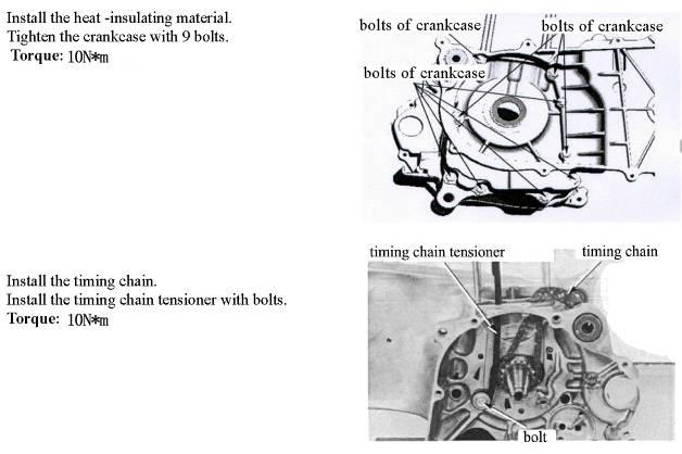
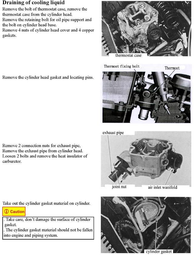
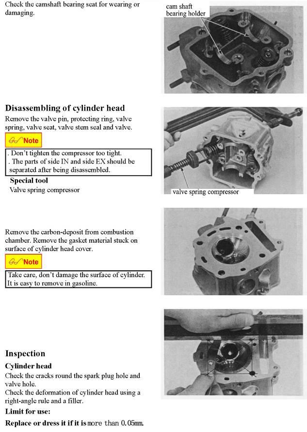
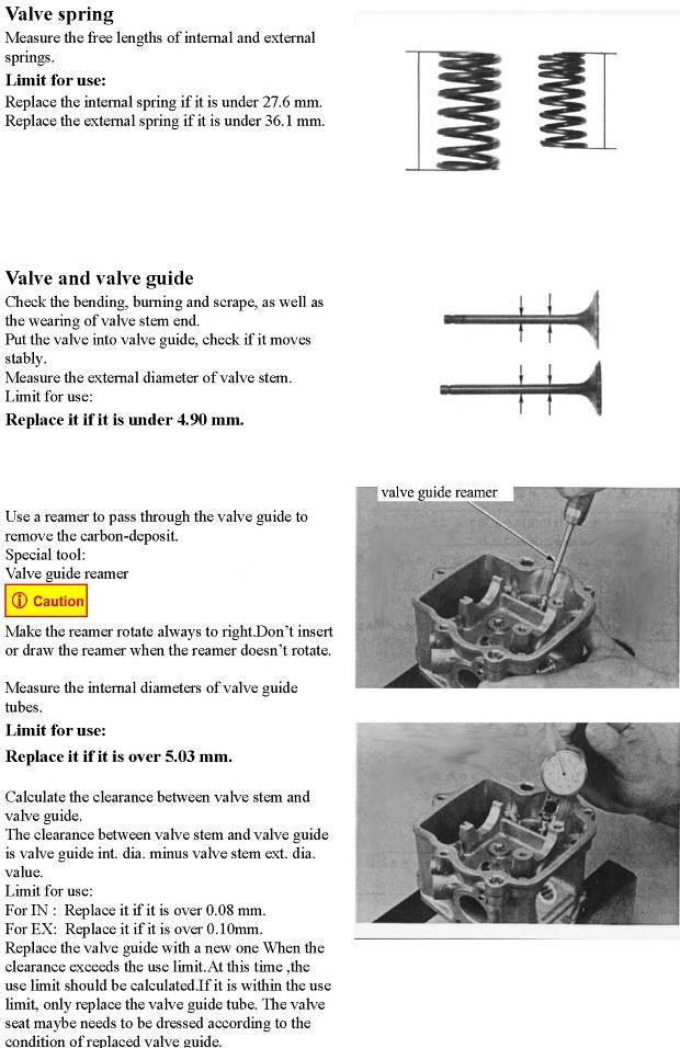
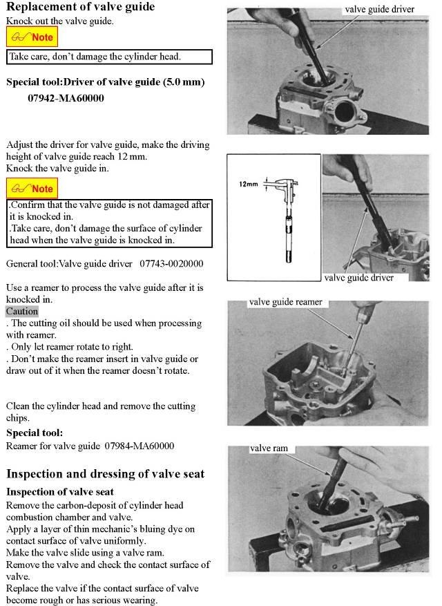
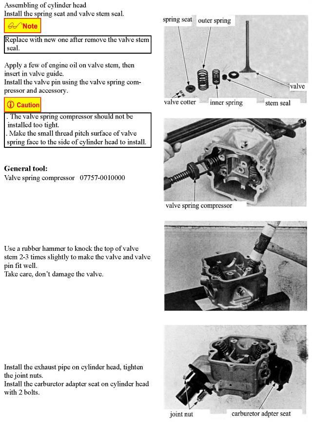
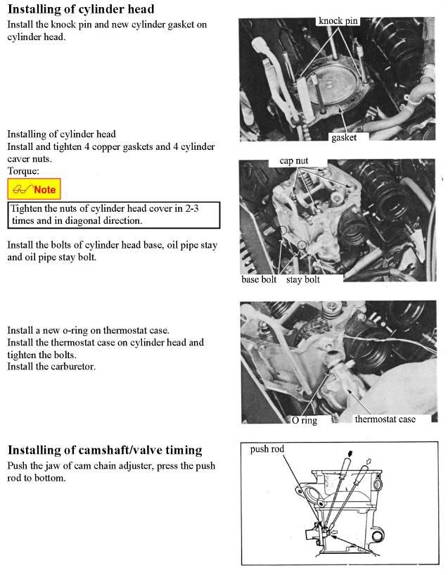
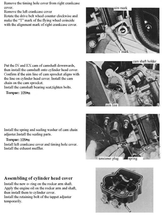
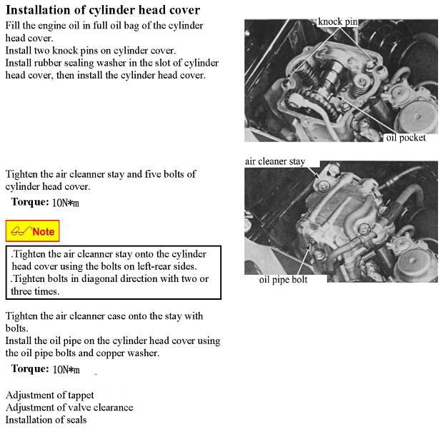
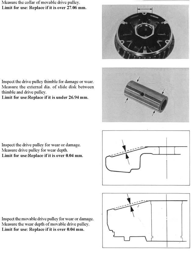
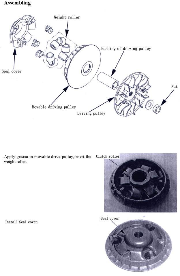
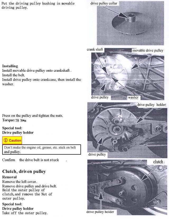
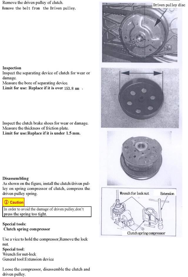
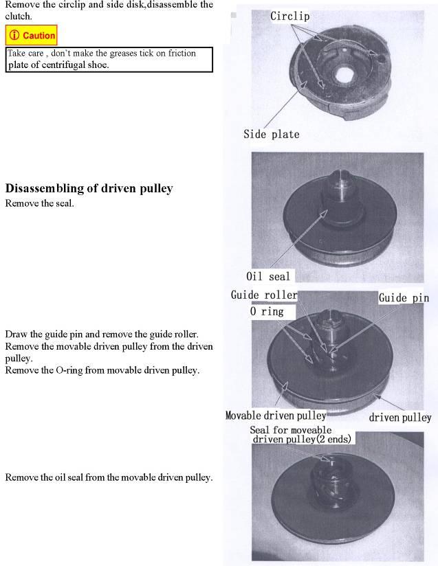
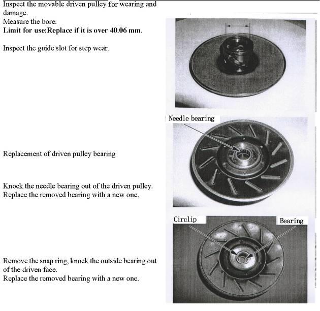
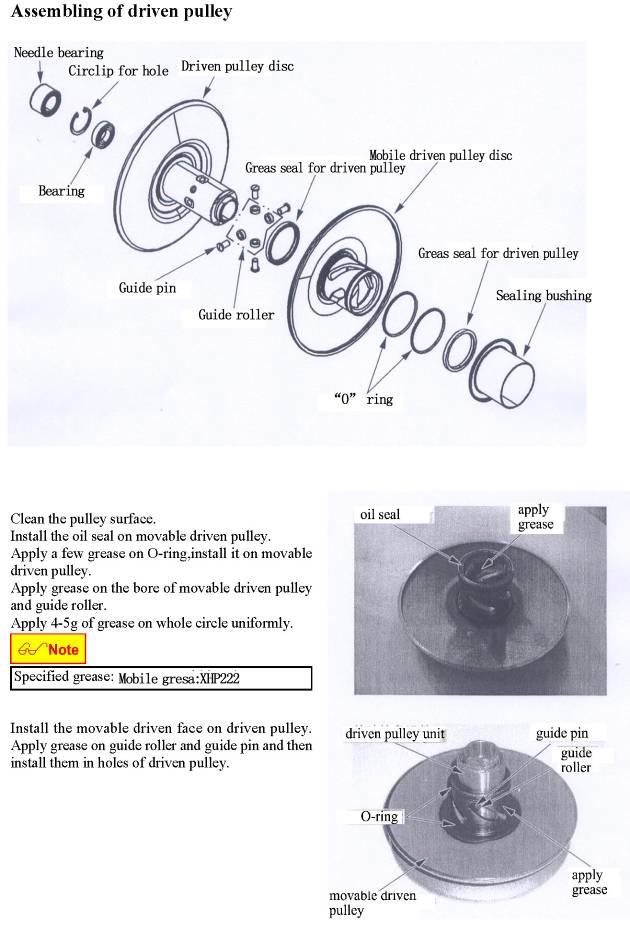
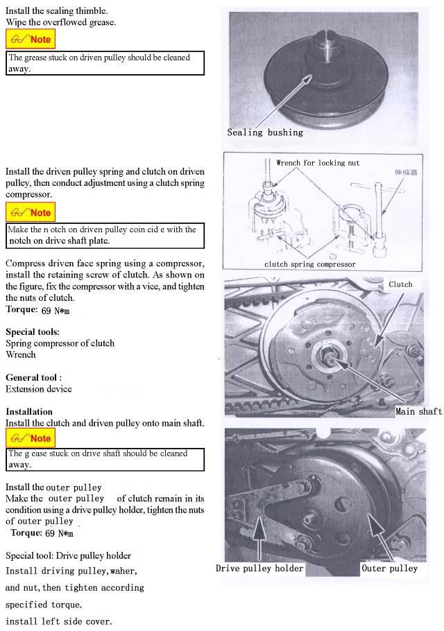
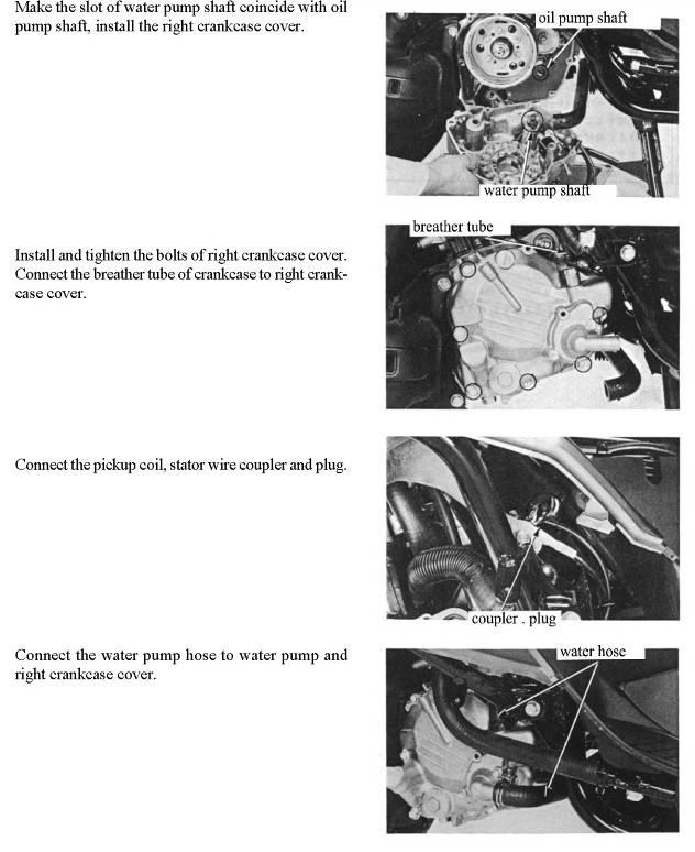
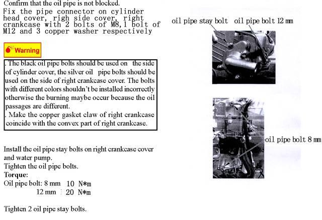
JNSZ250DN. Owner s Manual. Parts Manual MINIMUM RECOMMENDED OPERATOR AGE:
|
|
|
- Primrose Carpenter
- 5 years ago
- Views:
Transcription

1 Owner s Manual Parts Manual JNSZ250DN READ THIS MANUAL CAREFULLY IT CONTAINS IMPORTANT SAFETY INFORMATION. MINIMUM RECOMMENDED OPERATOR AGE: 16 FOR OFF-ROAD USE ONLY This vehicle is designed and manufactured for off-road use only. USA only: It does not confirm to federal motor vehicle safety standards and operation on Public streets, roads, or highways is illegal 0
2 CONTENTS WARRANTY POLICY... 3 OWNER S MANUAL FOREWORD A FEW WORDS ABOUT SAFETY IMPORTANT SAFETY INFORMATION SAFETY LABELS ARE YOU READY TO DRIVE? IS YOUR VEHICLE READY TO DRIVE? SAFE DRIVING PRECAUTIONS OPERATION SERVICE INSTRUCTION REPAIR ENGINE REPAIR INFORMATION ABOUT REPAIR INSPECTION, ADJUSTMENT AND MAINTENANCE COOLING SYSTEM CRANK CASE CYLINDER AND CYLINDER VALVE CYLINDER, PISTON CTV GEARBOX,GEAR SHIFT MECHANISM MAGNETO, STARTER, CLUTCH AND OIL PUMP CHASSIS REPAIR WIRING DIAGRAM PARTS MANUAL CRANKCASE ASSY SIDE COVER ASSY.L RIGHT COVER ASSY CYLINGDER HEAD CASEING ASSY CYLINGDER HEAD ASSY CYLINGER BODY ASSY TIMING CHAIN MAGNETOR ASSY ADMISSION MACHANISM CRANK LINK LEVER & PISTON SPEED CHANGER CLUTCH ASSY GEARBOX COVER ASSY TRANSMISSION GEAR ASSY GEAR SHIFT MACHANISM ENGINE OIL PUMP ASSY COOLANT PUMP ASSY ELECTRIC STARTER ASSY CARBURETOR ASSY
3 20 FRAME & FUEL TANK & RADIATOR FRONT SUSPENSION STEERING&THROTTLE&BRAKE&SHIFT ENGINE RACK & TRANSMISSION ENGINE ASSEMBLY EXHAUST,SHIFT& BRAKE REAR SUSPENSION ELECTRICAL PARTS OTHER PARTS PREPARATION ATTACH INSTRUCTION ATTACH BATTERY ATTACH PROTECTIVE BARS ATTACH REAR SHOCK ATTACH TRAILING ARM ATTACH FRONT SHOCK ATTACH FRONT TIRE ATTACH SEAT AND SAFT BELT ATTACH THE RADIATOR ATTACH SILENCER DEALER PRE-DELIVERY INSPECTION

4 WARRANTY POLICY 3
5 4
6 5
7 6
8 7
9 8
10 9
11 10
12 11
13 12
14 13
15 OWNER S MANUAL FOREWORD Thank you for choosing our Off highway recreational vehicle. We hope you will have fun with it. Before you start operate the Off highway recreational vehicle, please read through this Owner s Manual carefully as it contains important safety and maintenance information. Failure to follow the warnings contained in this manual can result in serious injuries. Be sure to follow the recommended maintenance schedule and service your Off highway recreational vehicle accordingly. Preventive maintenance is extremely important to the longevity of your Off highway recreational vehicle. We hope you will have a pleasant experience with our products and thanks again for choosing US. A FEW WORDS ABOUT SAFETY In order to keep everyone safe, you must take responsibility for the safe operation of your Off highway recreational vehicle. To help you make informed decisions about safety, we have provided operating procedures and other information on labels and in this manual. This information alerts you to potential hazards that could hurt you or others. It is not practical or possible to warn you about all hazards associated with operating or maintaining a Off highway recreational vehicle. You must use your own good judgment. You will find important safety information in a variety of forms, including: Safety Labels - On the Off highway recreational vehicle. Safety Messages Preceded by a safety alert symbol and one of two signal words: WARNING, or CUATION. These signal words mean: 14
16 Physical harm may result from failure to adhere to the instructions that are described within the WARNING labels. Safety Headings---It means Important Safety Reminders or Important Safety Precautions. Safety Section --- It means Go- Off highway recreational vehicle Safety. Instructions --- how to use this Go Off highway recreational vehicle correctly and safely. This entire manual is filled with important safety information----please read it carefully. IMPORTANT SAFETY INFORMATION Your off highway recreational vehicle will provide you with many years of service and pleasure. Providing you take responsibility for your own safety and understand the challenges you can meet while driving. There is much that you can do to protect yourself when you drive. You ll find many helpful recommendations throughout this manual. The following are a few that we consider most important. Follow the Age Recommendation It is strongly recommended that no one under the age of 16 be permitted to drive this off highway recreational vehicle without adult supervision. Always Wear a Helmet It s a proven fact: helmets significantly reduce the number and severity of head injuries. Always wear an approved motorcycle helmet. We also recommend that you wear eye protection, sturdy boots, gloves, and other protective gear. Drive Off-Road Only Your off highway recreational vehicle is designed and manufactured for off-road use only. The tires are not made for pavement, and the off highway recreational vehicle does not have some features required for use on public roads. Take Time to Learn & Practice Even if you have derived other off highway recreational vehicle, take time to become familiar with how this off highway recreational vehicle works and handles. Practice in a safe area until you build your skills and get accustomed to this off highway recreational vehicle s size and weight. Because many accidents involve inexperienced or untrained drives, we urge all drivers to take a training course approved by the off highway recreational vehicle Safety Institute. Check with your dealer for more information on training courses. Be Alert for Off-Road Hazards The terrain can present a variety of challenges when you drive off-road. Continually read the terrain for unexpected turns, drop-offs, rocks, ruts, and other hazards. Always keep your speed low enough to allow time to see and react to hazards. Drive within Your Limits Pushing limits is another major cause of off highway recreational vehicle accidents. Never drive beyond your personal abilities or faster than conditions warrant. Remember that alcohol, drugs, fatigue, and inattention can significantly reduce your ability to make good judgments and driver safely. Don t Drink and drive 15
17 Alcohol and driving don t mix. Even one drink can reduce your ability to respond to changing conditions, and your reaction time gets worse with every additional drink. So don t drink and drive, and don t let your friends drink and drive either. Never run your Go- Off highway recreational vehicle indoors. The exhaust from the engine contains a tasteless, odorless and poisonous gas called carbon monoxide. Keep away from moving parts of the off highway recreational vehicle The operator of the off highway recreational vehicle should never place their hands or other parts of their body near any moving part of the off highway recreational vehicle. Failure to adhere to this warning will cause physical harm to your body. Skidding or Sliding The terrain surface can be a major factor affecting turns, Skidding a turn is more likely to occur on slippery surfaces such as snow, ice, mud and loose gravel. If you skid on ice, you may lose all directional control. To avoid skidding on slippery terrain, keep you speed low and drive carefully. SAFETY LABELS This section presents some of the most important information and recommendations to help you drive your off highway recreational vehicle safely, Please a few moments to read these pages. The labels are considered permanent parts of the off highway recreational vehicle. If a label comes off or becomes hard to read, contact your dealer for warning labels replacements. 16

18 ! WARNING 17
19 Never shift or engage the reverse lever when the off highway recreational vehicle is in motion. Only engage the shift lever when the off highway recreational vehicle is at a full stop. Give a slight throttle and release throttle, then engage shift. Only shift from neutral. The shift lever must be in neutral and parking lever pulled when leaving the off highway recreational vehicle. ARE YOU READY TO DRIVE?! WARNING Do not shift when pushing throttle. Gear damage can occur. Gears are not warranted from shifting in motion or over running while shifting. Before each drive, you need to make sure you and your off highway recreational vehicle are both ready to drive. To help get you prepared, this section discusses how to evaluate your driving readiness, what items you should check on your Off highway recreational vehicle, and adjustments to make for your comfort, convenience, or safety. Before you drive your off highway recreational vehicle for the first time, we urge you to: Read this owner s manual and the labels on your off highway recreational vehicle carefully. Make sure you understand all the safety messages. Know how to operate all the controls. Have adult present if under 16 years old. Before each drive, be sure: You feel well and are in good physical and mental condition. You are wearing an approved motorcycle helmet (with chin strap tightened securely), eye protection, and other protective clothing. You don t have any alcohol or drugs in your system. Protective Apparel For your safety, we strongly recommend that you always wear an approved motorcycle helmet, eye protection, boots, gloves, long pants, and long-sleeved shirt or jacket whenever you drive. Although complete protection is not possible, wearing proper gear can reduce the chance of injury when you drive. The following suggestions will help you choose the proper driving gear. Helmets and Eyes Protection Your helmet is your most important piece of driving gear because it offers the best protection against head injuries. A helmet should fit your head comfortably and securely. An open-face helmet offers some protection, but a full-face helmet offers more. Regardless of the style, look for a DOT (Department of Transportation) sticker in any helmet you buy. Always wear a face shield or goggles to protect your eyes and help your vision. 18
20 Operating this Off highway recreational vehicle without wearing an approved motorcycle helmet, eye protection, and protective clothing could increase your chances of head and/or eye injury, possibly death in the event of severe accident. Always wear approved motorcycle helmet that fits properly and wear eye protection (goggles or face shield), gloves, boots, long-sleeved shirt or jacket and long pants. Additional Driving Gear In addition to a helmet and eye protection, we also recommend: Sturdy off-road motorcycle boots to help protect your feet, ankles, and lower legs. Off-road motorcycle gloves to help protect your hands. Driving pants with knee and hip pads, a driving jersey with padded elbows, and chest/shoulder protector. Drive Training Developing your driving skills is an on-going process. Even if you have driven other off highway recreational vehicles, take time to become familiar with how this off highway recreational vehicle works and handles. To build skills, Practice driving the off highway recreational vehicle in a safe area, do not drive in rough terrain until you get accustomed to the off highway recreational vehicle s controls, and feel comfortable with its size and weight. Operating Off highway recreational vehicle without proper instruction could increase your risk of an accident, which could lead to serious injury or death. Attempt supporting with your hands to the ground when the Off highway recreational vehicle turning over could lead to serious injury or death. Never support with your hands to ground when the Off highway recreational vehicle will turn over. Age Recommendation It is strongly recommended that no one under the age of 16 be permitted this off highway recreational vehicle without adult supervision. A child driving an Off highway recreational vehicle that is not recommended for his/her age could lose Off highway recreational vehicle control and result in severe injury or death. A child under 16 should have adult supervision when operate on the Off highway recreational vehicle. 19
21 No Alcohol or Drugs Alcohol, drugs and driving don t mix. Even a small amount of alcohol can impair your ability to operate the off highway recreational vehicle safely. Likewise, drugs-even if prescribed by a physician-can be dangerous while operating the off highway recreational vehicle. Consult your doctor to be sure it is safe to operate a vehicle after taking medication. Operating this Off highway recreational vehicle after alcohol or drugs can seriously impaired your judgment, balance, perception, and judgment. This can result in serious injury or death. Never consume alcohol or drugs before or while operating this Off highway recreational vehicle. IS YOUR VEHICLE READY TO DRIVE? Before each drive, it s important to inspect your Off highway recreational vehicle and make sure any problems are corrected. A pre-drive inspection is necessary, not only for safety, but also for comfort. Because having a breakdown, or even a flat tire, can be a major inconvenience. If your off highway recreational vehicle has overturned or has been involved in a collision, do not drive it until your dealer has inspected your off highway recreational vehicle, There may be damages or other problems you cannot see. Improperly maintaining this Off highway recreational vehicle or failing to correct a problem before driving can cause a crash in which you can be seriously hurt even die. Always perform a pre-drive inspection before every drive and correct each problem. Pre-drive Inspection Check the following items before riding the off highway recreational vehicle: Engine Oil Check the oil level add oil if needed. Check for leaks. Fuel Check the fuel level add fuel if needed. Also make sure the fuel fill cap is securely fastened. Check for leaks. Tires Use a tire gauge to check the air pressure. Adjust if needed. Also look for signs of damages or excessive wear. Nuts & Bolts Check the wheels to see that the axle nuts are tightened, Use a wrench to make sure all accessible nuts; bolts, and fasteners are tight. Under body & Exhaust System Check for and remove any dirt, vegetation or other debris that could be fire hazard or interfere with the proper operation of the off highway recreational vehicle. Air Cleaner Housing Drain Tube 20
22 Check for deposits in the drain tube. If necessary, clean the tube and check the air cleaner housing. Leaks, Loose Parts Walk around you off highway recreational vehicle and look for anything that appears unusual, such as a leak or loose cable. Lights Make sure the headlight; brake light and taillight are working properly. Throttle Check the free play and adjust if needed. Press the throttle to make sure it moves smoothly without sticking, and snaps back automatically when it is released. Brakes Press the brake pedal several times, check for proper brake pedal free play. Make sure there is no brake fluid leakage. Steering Wheel Check that the wheels turn properly as you turn the steering wheel. Cable Check the cable housing for wear. Check the fittings for looseness. Replace or tighten as needed. Tie rod Check the tie rod housing for wear. Check the fittings for looseness. Replace or tighten as needed. SAFE DRIVING PRECAUTIONS Off-Road Use Only You off highway recreational vehicle and its tires are designed and manufactured for off-road use only, not for pavement. Driving on pavement can affect handling and control. You should not drive your off highway recreational vehicle on pavement. Operating this Off highway recreational vehicle on paved surfaces may seriously affect handling and control of the Off highway recreational vehicle, and may cause the vehicle to go out of control. Never operate the Off highway recreational vehicle on any paved surfaces, including sidewalks, driveways, parking lots and streets. When driving off-road, also remember to always obey local off-road driving laws and regulations. Obtain permission to drive on private property. Avoid posted areas and obey no trespassing signs. You should never drive your off highway recreational vehicle on public streets, roads or highways, even if they are not paved. Drivers of street vehicles may have difficulty seeing and avoiding you, which could lead to a collision. In many states it is illegal to operate off highway recreational vehicles on public streets, roads and highways. Operating this Off highway recreational vehicle on public streets, roads or highways can cause collision with other vehicle. Never operate this Off highway recreational vehicle on any public streets, roads or highways, even dirt or gravel one. 21
23 Keep Hands and Feet on Controls Always keep both hands on the steering wheel and both feet on the foot controls. When driving your off highway recreational vehicle. It is important to maintain your balance and to control of the off highway recreational vehicle. Removing hands or foot away from the controls can reduce your ability to react control of the off highway recreational vehicle. Removing hand from Steering wheel or feet from foot controls during operation can reduce your ability to control the Off highway recreational vehicle. Always keep both hand on the steering wheel and both feet on the foot controls of you re Off highway recreational vehicle during operation. Control Speed Driving at excessive speed increases the chance of an accident. In choosing a proper speed, you need to consider the capability of your Off highway recreational vehicle, the terrain, visibility and other operating conditions, plus your own skills and experience. Operating this Off highway recreational vehicle at excessive speeds increases your changes of losing control of the Off highway recreational vehicle, which can result in an accident. Always drive at a speed that is proper for you re Off highway recreational vehicle, the terrain, visibility and other operating conditions, and your experience. Use Care on Unfamiliar or Rough Terrain Before driving in a new area, always check the terrain thoroughly. Don t drive fast on unfamiliar terrain or when visibility is limited. (It s sometimes difficult to see obstructions like hidden rocks, bumps, or holes in time to react). 22
24 Failure to use extra care when Operating this Off highway recreational vehicle on unfamiliar terrain could result in the Off highway recreational vehicle overturning or going out of control. Go slowly and be extra careful when operating on unfamiliar terrain. Always be alert to changing terrain conditions when operating the Off highway recreational vehicle. Never drive past the limit of visibility. Maintain a safe distance between your off highway recreational vehicle and other off-road vehicles. Always exercise caution and use extra care on rough, slippery and loose terrain. Failure to use extra care when operating on excessively rough, slippery or loose terrain could cause loss of traction or vehicle control, which could result in an accident, including an overturn. Do not operate on excessively rough, slippery or loose terrain until you have learned and practiced the skills necessary to control the Off highway recreational vehicle on such terrain. Always be especially cautious on these kinds of terrain. Do Not Perform Stunts You should always operate your off highway recreational vehicle in a safe and reasonable manner. When driving, always keep all four wheels on the ground. Attempting wheelies and other stunts increases the chance of an accident, including an overturn. Never attempt stunts, such as wheelies or jumps. Don t try to show off. 23
25 SPECIFICATIONS DIMENSIONS Overall Length in. (2500mm) Overall Width in. (1520mm) Overall Height in. (1570mm) Wheelbase in. (1970mm) Front Track in. (1300mm) Rear Track in. (1290mm) Ground Clearance in. (300mm) ENGINE Type liquid-cooled. 4-Stroke Bore x Stroke mm 60mm Displacement cc Corrected compression ratio :1 Carburetor KEI HIN: No. VE 14CEQKY Output Power hp/7000rpm Maximum Torque Nm /5500r/min Starting Electric Ignition C.D.I Lubrication Force & Splash Transmission Automatic (C.V.T system) Spark Plug DPR7EA-9 (NGK) Plug gap mm Fuel type RQ90 (unleaded) Lubricate oil SAE-10W/30 CAPACITIES Maximum load Ibs Fuel tank L Engine oil ml Gear oil ml Coolant ml Starting <5s Climbing Battery V 9Ah Head Light V 15W Tail Light V 5W/10W/21W Fuse A Brake Track < 20miles/h Top speed miles/h (or limited as customers require) CHASSIS Front, Rear brake Hydraulic disc, right foot control Front tire Rear tire Front Suspension Independent Dual A-Arm Rear Suspension Trailing Arm/Double Oil& Damped Shock Restraint System Dual 4-point Harness Final Drive Chain Ax62 TIRE PRESSURE Front kpa 6.1psi Rear kpa 8.1psi WEIGHT Net Weight kg/ 771lbs WARRANTY Parts and workmanship Days 24


26 OPERATION A. Operation controls WARNING-Do not attempts to start or operate the engine until completely familiar with the location and use of each control necessary to operate this vehicle. The operator must know how to stop this machine before starting and driving it. a. Throttle The right foot pedal is the throttle that controls the off highway recreational vehicle speed. As the engine speed increased above idle, the clutch automatically engages and moves the vehicle forward. Allow the throttle to return to the idle position at any time, and the clutch disengages. (See Fig. 1) Each time prior to starting the engine, check the throttle assembly to ensure that when pedal is pushed all the way forward the assembly is working smoothly and returns to idle when released. Do not operate if pedal or engine throttles linkage fail to return to idle. If unable to correct the problem through lubrication, adjustment or replacement of worn parts, contact your dealer for assistance. b. Brake The brake is located on the left side of the off highway recreational vehicle (See Fig. 1). Applying pressure to the pedal draws the brake caliper around the brake pump at the 4 wheels and slows or stops the off highway recreational vehicle. BRAKE PEDAL THROTTLE PEDAL c. Start engine Insert the key into key-switch, turn the key clockwise, and release the key when the engine starts. The engine will warm up for 5 minutes and the engine choke will close automatically and run at normal RPM (Warning: Don t crank starter more than 5 seconds at one time). (See Figure 2) d. Run you Off highway recreational vehicle Press the shift lever forwards to L position, the cart will move forwards at low speed, H position, high speed; N position, no speed; and R position the cart will move backwards. (Note: if the shift can t engage, give a slight throttle, and then try it again) RPM INDICATOR ODOMETE HORN BUTTON Figure 1 WATER TEMPERATURE INDICATOR Figure 2 VOLTAGE METER IGNITION START SWITCH 25


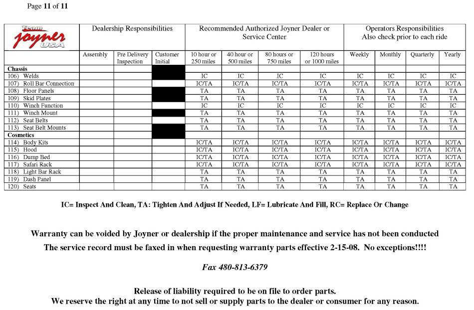
27 If the shift engages press down the throttle pedal slowly, the cart will accelerate. (See Figure 2) e. Operate lights See figure 4, press down the button, the corresponding light will run. And if move the shift lever to L position, the L light will shine, H position, the H light, N position, the N light, and R position, the R light, DIPPED BEAM HEADLIGHT HIGHT BEAM HEADLIGHT Figure 3 SHIFTER LEVER SHIFTER INDICATOR SHIFTER INDICATOR TURNNING LIGHT Figure 4 SPOT LAMP B. Pre-Drive Inspection Perform this pre-drive inspection every day before driving vehicle. If not performed, serious damage to the vehicle or personal injury may result. a. Check for Engine Oil Level. Check for leaks, add oil if required. b. Check for Fuel Level. Add fuel as necessary and do not overfill. Check for leaks c. Check for Brakes. Depress the rear brake pedal several times, and then check for proper brake pedal free play. Make sure there is no brake fluid leakage. Adjust if necessary. d. Check Tires. Check tires condition and pressure. The pressure on both Front and Rear tire is 42kpa/6.1PSI and 56kpa/8.1PSI. e. Check Drive Chain. Check for drive chain s condition and tension. Lubricate if necessary. f. Check Throttle. Check for smooth operation. Assure throttle snaps back to idle. g. Check Engine Stop Button. Perform engine stop button test. Repair as necessary. h. Check all Nuts, Bolts, and fasteners. Check wheels to see that all axle nuts and lug nuts are tightened properly. Check and tighten as necessary all other fasteners to specified condition. i. Check Roll Cage Bar. Ensure all protective roll cage bar are in place before operating the off highway recreational vehicle. j. Check Brake Light. Check for proper operation. k. Check Wheels. Check for tightness of wheel nuts and axle nuts; check that axle nuts are secured by cotter pins. 26
28 l. Check Steering. Check for free operation for any unusual looseness in any area. Always follow rules for safe operation and wear a helmet. 27

29 m. Component locations SAFETY BELT SPOT LIGHT RADIATOR STEERING WHEEL HEAD LIGHT FRONT TURN SIGNAL FRONT SHOCK FRONT ARM AXLE NUTS WHEEL NUTS RADIATOR RADIATOR CAP ROLL BAR FUEL TANK RESERVE TANK BATTERY BATTERY BRAKE LIGHT MUFFLER REAR SHOCK CV SHAFT REAR TIRE C. Passengers 28


30 The vehicle allows for two riders only. Combine maximum weight of driver and the passenger should not exceed 180kg (400Ibs). D. Seat Adjustment The seat must always be securely fastened in the position which best affords the operator control of the foot pedals, steering wheel, and the remote stop button. a. Pull seat adjustment handle upward to disengage seat slide. b. Move seat to desired position. c. Be sure seat adjustment handle snaps back into place and that seat is locked into position. Seat adjustment handle Figure 5 Before attempting to adjust the seat ensures that engine of the Off highway recreational vehicle is stopped. Never operate this Off highway recreational vehicle when the provided seat is not securely fastened, to do so could result in a strong possibility of severe personal injury or loss of life. Before attempting to adjust the seat ensure the engine of the Off highway recreational vehicle is stopped. E. Shift Adjustment a. Press down the shift lever to the L position so that the unit can move forward at low speed, press the lever to H position so that the unit can move forward at high speed, Pull back the shift to N position so that the unit can t move, pull back the lever to R so that the unit can move backward. (See Fig. 6) ADJUSTMENT NUTS b. Loosen lock nut, and remove the cotter pin and the plain washer. Rotate the joint, the shifter lever will rotate clockwise or counter clockwise, so you can adjust the lever in proper position JOINT LOCK NUT Figure 6 29

31 Never engage the shift lever when the Off highway recreational vehicle is in motion Only engage the shift lever when the off highway recreational vehicle is at a full stop Give a slight throttle and loosen throttle, then engage shift from neutral to shift. The shift lever must be on neutral and pull parking lever when leave the Off highway recreational vehicle F. Parking Adjustment Press down the reverse lever to the F position so that the unit can move forwards; pull back the lever to P so that the unit can park. (See Fig. 7) Adjust Nut #1; Make sure cable is not too tight or too loose. Adjust Nut #2 accordingly to adjustment of Nut #1. (See Figure 7) NUT #1 NUT #2 G. Starting And Operating Instructions a. Before starting the engine, be sure that the driver is seated properly in the off highway recreational vehicle and tighten the seat belt. b. Testing the Off highway recreational vehicle in an open place at the beginning to learn how to start, turn and stop. c. Operate the Off highway recreational vehicle slowly until you are familiar with it. d. The turning radius of this off highway recreational vehicle is small and agile, so the centrifugal force is very high when turning at high speed. Slow down to a more controllable speed when turning to prevent the off highway recreational vehicle from rolling over. e. To prevent vehicle from rolling over, be sure to only turn the vehicle at a slow more controllable speed. Heel on the ramp of the main board when turning, Keep your leg rely on the foot pedal, you can feel the off highway recreational vehicle is stable because of the gravity is adjusted and won t roll over. Figure 7 PUSHING BAR H. Foot brake adjustment a. Loosen the thin nut M8 b. Rotate the pushing bar to make space proper. c. Tighten thin nut M8. d. With the same way to adjust another pair. THIN NUT M8 Figure 8 30


32 SERVICE INSTRUCTION A. Air Filter. Clean every 80 running hours. If Filter core the vehicle is operated under Cover 1 extremely dusty condition, we suggest cleaning after every use and replace more often. a. Remove cleaner cover 1. b. Remove air cleaner filter core (See Fig. 9) c. Check the filter paper, if the filter paper is dusty, please clean with pressure air or replace with a new one B. Engine Lubrication Figure 9 You must change the oil in the crankcase after the first 5 hours of operating of your new engine and after 10 hours of use thereafter. That will insure proper lubrication of internal parts and prevent costly repairs due to excessive wear. Never operate this Off highway recreational vehicle when the provided seat is not securely fastened, to do so could result in a strong possibility of severe personal injury or loss of life. a. Remove fill plug located on bottom of engine (See Fig. 10). Tip Off highway recreational vehicle backwards slightly by blocking up the front end and drain oil into suitable container. b. Replace fill plug and tighten securely. Place Off highway recreational vehicle in a level position. c. Refill crankcase (approximately 1000 ml/1qt) to top of filler neck with SAE 10W/30 oil. Use same grade of oil as used originally. d. Check oil level before each use of dart or after each 10 hours of operation. Add oil to bring up to proper lever. Do not mix various grades of oil. OIL INLET Figure 10 OIL INLET C. Engine Coolant You should check the coolant for lack. If lack, you should refill coolant (approximately 1800 ml) into the radiator or reserve coolant. The lack of coolant will cause engine overheat. This can cause engine damage. D. Spark Plug a. Remove the spark plug and inspect it (Use a spark plug wrench) The electrodes should be kept clean and free of carbon. The presence of carbon or excess oil Figure 11 31

33 will greatly reduce proper engine performance. If possible, check the spark plug gap (area between electrodes) using a wire feeler gauge. This specification is ~ (See Fig. 11) b. Before installing spark plug coat threads lightly with graphite grease if possible, to ensure easy removal next time the spark plug needs inspection. c. It is advisable to replace the spark plug at least once a year to insure easy starting and good engine performance. E. Carburetor Adjustment Never make unnecessary adjustments. The factory recommended settings are correct for most applications. It s not necessary to disassemble the screw unless the carburetor needs to be replaced. Prepare a 50r/w tachometer before adjustment. a. Warm up the engine (5~10min) b. Tighten the airscrew gentle. Back out 2-3/8 turns counter clockwise. c. Connect the tachometer; adjust the throttle to limit the idle speed. The standard value is (1500RPM). d. Turn the airscrew slowly and observe the RPM of the engine, stop adjusting as the RPM reaches the top speed. e. Adjust the screw and adjust the idle speed to an ideal value. f. Repeat step d and e until the rotate speed of engine stables. Figure 12 F. Cleaning Instructions Keep your off highway recreational vehicle clean. With a clean rag, wipe off and dirt and oil from around controls. Wipe off any spilled fuel and oil. Keep the engine clean off foreign object and be sure to check that air intake fan is free off debris for proper cooling. G. Off highway recreational vehicle Lubrication Lubricate vehicle every 90 days of use, Apply several drops of lithium grease in arrow-pointed points in the following picture. 32


34 Front arm Rear arm Tie rod Steering shaft & Arm 33
 a.")

35 H. Chain Lubrication I. To increase chain life, it should be Lubricated with a spray or Chain lubricant. J. Chain Adjustment Check the chain adjustment after first two hours of use. Readjust if it has more than 1/2 flex. (See figure 13) a. Loosen NUT #1, and NUT #2. b. Rotate BOLT #1, the BEARING BLOCK will move forwards or backwards, so the chain will become loose and tight. Repeat this procedure until chain is at proper tension. c. Tighten all of the nuts. NUT #2 NUT #1 BOLT #1 Figure 13 J. Adjustment of Front and Rear Shock 34
36 There are five adjustable positions on each Front shock. The default position is in the first set by manufacture (See Fig.14) Use a round nut wrench as you adjust the front shock, the tension of shock spring will increase as you screw to left, decrease as you screw to the right. There is screw on the rear shock; use shock wrench as you adjust the rear shock, the tension of shock spring will increase as you screw to right, decrease as you screw to left. (See Fig.15) LEFT ROTATE RIGHT ROTATE LEFT ROTATE RIGHT ROTATE SPRING ADJUSTMENT CAM Figure 14 Figure 15 K. Storage Instruction In the event you re off highway recreational vehicle is not to be operated for periods in excess of 30 days or at the end of each driving season prepare for storage as follows: a. Drain fuel tank and carburetor by allowing engine to run out of fuel, or use a fuel stabilizer. b. Lubricate engine cylinder by removing the spark plug and pour one ounce of clean lubricating oil through the spark plug hole into the cylinder. Crank the engine slowly to spread oil and replace spark plug. c. Do not save or store gasoline over winter. Using old gasoline, which has deteriorated from storage, will cause hard starting and affect engine performance. Do not drain fuel while engine is hot. Be sure to move Off highway recreational vehicle outside before draining fuel. 35
37 REPAIR ENGINE REPAIR Units translation form Item Example Unit conversion Pressure 200kpa(2.00kgf/cm 2 ) 33kpa(250mmHg) 1kgf/cm 2 = kpa 1kpa=1000pa 1mmHg= pa= kpa Torque 18N. m(1.8kga. m) 1kgf. m= n. M Volume 419ml 1ml=1cm 3 =1cc 1L=1000cm 3 Force 12N(1.2kgf) 1kgf= N Explanation for symbols in manual That dangerous items,need to pay special attention. Or it will cause accident even death., Important item need to pay some attention, otherwise, the engine will be damaged and stop running., General notes and tips. 36

38 INFORMATION ABOUT REPAIR Engine number location Engine number Specification table No. Item specification 1 Engine Model 172MM-C 2 Displacement 244.3CM 3 3 Types of fuel RQ-90 4 Starting electric 5 Type Single-cylinder, four-stroke water-cooled, vertical 6 Bore Stroke 72mm 60mm 10 7 Compression pressure 1470kpa-600rpm 8 The maximum power 11kw/7000rpm 9 Maximum torque 17.6N m/5500rpm Distribution phase Intake valve Exhaust Valve Open Closed Open Closed BTDC0 (1mm) ABDC30 (1mm) BBDC35 (1mm) BTDC5 (1mm) 11 Unladen stability minimum rpm 1500±150rpm 12 Lubrication system Lubrication type Pump type Lubricating oil filter type Pressure/ Splashing Rotor Metal strainer full-flow filtration 37

39 Lubrication capacity 1.0L 13 Cooling Compulsory 14 Fuel system Electric System al Power transmission system Air Filters Carburetor Ignition way Ignition time Spark Plug Electrode gap Clutch type Transmission Type Foam plastic fitter core KEIHNCV30 C.D.I Electronic ignition 10 BTDC 1500rpm DPR7EA-9(NGK) mm Dry-foot block automatic centrifugal CVT+Gearbox Continuously variable rate Gear box rate Gears High Low reverse Primary secondary Power output Sprocket output Inspection parameters table Lubrication device Item Standards Limit When the replace oil 0.8l - Engine oil capacity Full capacity 1.0l - Recommended engine oil: 4-stroke motorcycle specified oil AE-10W-40 20W-50d to use a substitute oil, follow the following items: API classification: SF,SE SAE specification: Choose one from the left illustration according temperature. (Temperature) Gap between rotors of Inside 0.15mm 0.20mm and outside oil pump rotor Oil pump Gap 0.15~0.23mm 0.25mm Face Gap 0.05~0.10mm 0.12mm 38
40 Cylinder Head Valve Item Standards Limit Cylinder compression pressure 1470kpa-600rpm Valve Clearance IN 0.10mm EX 0.10mm Planeness of the surface Cylinder Head connect 0.02mm 0.05mm Camshaft Height of cam top IN mm 31.52mm EX mm 31.52mm Valve Rocker inner diameter IN/EX mm 12.1mm Rocker Rocker outer diameter IN/EX mm 11.91mm Valve shaft diameter IN mm 4.90mm EX mm 4.90mm Valve guide sleeve inner IN mm 5.03mm Valve, diameter EX mm 5.03mm Valve Gap between valve shaft IN mm 0.08mm guide and valve guide sleeve EX mm 0.10mm sleeve Depth of the hole in valve guide sleeve seat IN/EX 12/12mm Valve seat width in contact IN/EX 1.1mm 1.8mm Valve Free length( outer spring/ Spring Inner spring) IN/EX 40.0/30.5mm 36.0/27.5mm 39
41 CVT Item Standard Limit Transmission mobile-disc-unite hole inner diameter mm 27.06mm Transmission Driving wheel disc sleeve outer mm 26.94mm driving pulley diameter Centrifugal roller unite outer diameter mm 22.4mm Belt width 24.2±0.5mm 22.5mm Friction plate thickness 1.5mm inner diameter of clutch outer mm 153.8mm wheel disc Clutch Driven free length of clutch spring 135.0mm 127.0mm pulley Outer diameter of driven wheel mm disc bushing 39.94mm Inner diameter of mobile driven mm wheel disc 40.06mm Speech reducing mechanism Volume of oil Recommended oil Starting motor Item When replacing When disassembling Standards 0.75l( fill to neck) 0.85l(fill to neck) SAE10W-40/SF Grade Item Standards Limit the use of Starting motors Brush length 10mm 7mm Crankshaft Pistons Cylinder Item Standards Limit ( Units mm) ( Units mm) Connecting Axial clearance mm Crankshaft rod tip Radial clearance mm 0.05mm Crankshaft run-out tolerance 0.02mm 0.10mm Pistons installation direction IN point to intake valve Pistons diameter mm 71.9mm Pistons pin hole diameter mm 17.03mm Piston Pin diameter mm 16.98mm Pistons Clearance between cylinder and mm piston 17.04mm Clearance between piston and piston pin mm 0.15mm Clearance between piston pin and connecting rod mm 0.04mm 40
42 Piston pin and linkage between mm the gap 0.06mm Clearance Piston Ring(1) mm 0.09mm between Piston groove Ring and piston ring Piston Ring(2) mm 0.09mm Piston Ring(1) mm 0.05mm Piston Ring cut Piston Ring(2) mm 0.05mm gap Oil ring mm Piston Ring installation direction mark upward Diameter mm 72.1mm Cylinder Planeness of upper surface 0.05mm Roundness 0.002mm 0.05mm Cylindricity 0.005mm 0.05mm Battery charge devices Item Standards Type Permanent Magnet AC AC Magneto Output Three-phase AC Charging coil resistance(20 ) Ω Rectifier type Three-phase ring rectifying, SCR 41
43 Attention Washer O ring cotter pin and spring washer need to be replaced with a new on after disassembly. before tightening bolt, nut and screw, rotate the hardware several rounds and make sure screws can match well, then tighten the hardware from big to small, from inside to outside and with the specified torque. only CF parts, or recommended part, grease and oil always use special tools and general tools when necessary. before measure and check the parts taken off, make sure it is clean, and apply some oil before install back. 42
44 must smear or inject specified grease or oil on the special points. check every tightened points and all the mobile parts after assembly. 43
45 Engine torque table Hardware specification Torque required Where is the hard ware Nut M N M Fixing transmission Nut M N M Fixing clutch Nut M N M Fixing flywheel Cap-Nut M8 30N M Matching the stud fastening cylinder Cylinder stud 30N M Fixing crankcase assembly Filter net cover 20N M Right-covered Lvyou Bolt M N M Right case filter hole Inner hex bolt M N M Fixing clutch Reamed boltsm N M Fixing oil pipe M7 1(left) 12N M Coolant pump impeller Bolt M8 10N M Oil pipe reamed bolt Bolt M8 10N M Exhaust pipe bolt M8 1 10N M Tension spring seat bolt M N M Spark Plug Bolt M N M Oil outlet bolt Screw M4 12 5N M Oil stop plate on gearbox cover Bolt M5 10 8N M Seal pressure plate on gearbox Bolt M N M oil outlet plug bolt on gearbox M N M Oil inlet plug bolt on gearbox Round Nut M N M Fix driving bevel gear BoltM N M Fix driven bevel gear Hollow bolt M N M Fix gear-shift stopping ball Torque table for the other bolts and nuts specification Torque N m(k g f m) specification Torque N m(k g f m) 5mm Bolt Nut 5(0.5) 5mm Screw 4(0.4) 6mm Bolt Nut 10(1.0) 6mm Screw 9(0.9) 8mm Bolt Nut 22(2.2) 6mm SH Flanged bolts 10(1.0) 10mm Bolt Nut 34(3.5) 6mm Flanged bolts nuts 12(1.2) 12mm Bolt Nut 54(5.5) 8mm Flanged bolts nuts 26(2.7) 10mm Flanged bolts nuts 39(4.0) 44
46 172MM-B 172MM-c Special tools No. Tools name Specification Used for Remarks chapter 1 Bearing-removed tool 12mm Bearing 6201 Work with8,9 9 2 Bearing-removed tool 15mm Bearing 6202 Work with8,9 4,9 4 Bearing-removed tool 17mm Bearing 6303 Work with8,9 9 5 Bearing-removed tool 20mm Bearing 6304 Work with8,9 9 6 Bearing-removed tool 22mm bearing on the left of main shaft Work with8,9 9 7 Bearing-removed tool 25mm Bearing 6305 Work with8,9 9 8 Handle for bearing removed-tool 4,9 9 Balance block for bearing removed tool 4,9 10 Bearing guide 12mm Bearing 6201 Work with Bearing guide 15mm Bearing 6202 Work with Bearing guide 17mm Bearing 6303 Work with Bearing guide 20mm Bearing 6304 Work with Bearing guide 22mm bearing on the left of main shaft Work with Bearing guide 25mm Bearing 6305 Work with Handle for bearing-pushed tool 9 17 hook wrench 34~36mm Round nut 9 18 Punch Riveting 9 19 Water-Seal-removed tool Water Seal static ring 4 20 Bearing tools 28 30mm pushing oil seal on water pump 4 21 Valve Guide Reamer Processing valve guide 6 22 Valve Guide-removed tool Removing valve guide 6 23 Belt wheel support Stopping belt to run 8 24 Clutch spring Assembling or disassembling compressor driven pulley 8 25 Flywheel-removed tool Disassembling flywheel Fixing-nut wrench Assembling or disassembling driven pulley 8 45
47 Grease, seal glue, threads glue Appling point Attention type coolant temperature sensor threads locking threads of timing sprocket fixing screw glue Driven wheel ball bearings(690iuu) Driven wheel needle roller bearings g(don t smear to the Driven round of movable round action-driven driven- belt Multi-purpose groove working-surface) grease O-ring sealing surface seal lip Combination of speed reducer Plane sealant 46

48 Engine oil pathway Outer oil pipe unit Oil filter net Oil Pump Oil outlet bolts 47
49 48
50 49
51 50
52 51
53 INSPECTION, ADJUSTMENT AND MAINTENANCE Period Hour 20h running in Every 40h Every 80h Remark Item Month Match condition, non-normal sound I I I exhaust condition I I I no blue or black gas Engine body In:0.08~0.12 valve gap I I I Out:0.08~0.12 idle speed I I I 1500±150RPM I I I No carbon, spark plug gas between Replace every 6000km poles:0.8~0.9mm Air filter C C C Fuel pipes on carburetor Replace every 4 years Driving belt - I R Dirty, quantity I I I Lubrication leakage I I I oil filter I - I oil replacement R - R Coolant quantity I I I Coolant pipe I I I Cooling Opening pressure of radiator valve I I I Coolant replacement every 2 years transmission leakage,quantity I replace every one year Clutch If work I I: inspection; C: clean; R: replacement The period in the table above is for normal condition; shorten the period if the using condition is dirtier. 52

54 Check the quantity of gearbox oil To check the oil level. Put the engine or vehicle on a flat floor, turn off the engine, and take off the oil-filling bolt, fill the specified oil until the oil lever get up to the lip. If lack of oil, fill the specified oil with the same way. Specified oil: SAE10W-40, SE-API; Before put the oil-filling bolt back, make Sure the seal washer is not damaged. Replace the oil in gearbox Oil-filling bolt Oil-draining bolt Oil-draining washer 1. Remove the oil-filling bolt 2. To drain oil in the gearbox, Remove the oil-draining bolt. 3. Put back the oil-draining bolt. 4. Fill in the gear box with specified oil Specified oil: SAE10W-40, SE-API Oil capacity: 0.75L 5. Install the oil-filling bolt back. 6. Start engine, check if leak and quantity. Make sure all the O-ring and seal-washer are not damaged. Oil-ring Oil-draining washer Oil-draining bolt Oil-filling bolt Driving belt pulley and driven belt pulley 1. Take of left side cover. 2. Check the wear condition on the driving belt pulley and driven belt pulley. 3. If wore out, measure the depth of wearing. (Refer to related instruction) 53


55 Spark plug 1. Removing the spark plug. 2. Check the spark plug if damage, dirty or sediment. 3. If dirt or sediment, clean with spark plug cleaning tool or cleaning brush. Adjust the gap of spark plug if necessary Specified gap of spark plug DPR7EA-9NGK To install spark plugs, rotate the spark plug with hand until can t rotate anymore. Then fasten the spark plug with spark plug sleeve. Torque:18N m Idle adjustment Adjust the idle speed after the engine warm up. if the carburetor was repaired, adjust the idle speed after adjust air-regulating screw. According the related requirement, do the following operation: Worm up engine Connect RPM indicator. Rotate valve stopping screw clockwise or count-clockwise until the RPM indicator display 1500± 150rpm If the idle speed is not steady or the RPM change after operate the throttle pedal, just adjust air regulating screw according third chapter. Valve stopping screw 54

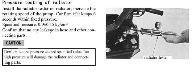
56 The maintenance for air filter 1. Take off the air filter unite. 2. Disassembly 5 self-taping screws from air filter unite, and take off the left cover. 3. Remove cleaner cover. 4. Remove air cleaner filter core. 5. Check the filter paper, if the filter paper is dusty, please clean with compressed air or replace with a new one If the vehicle is operated under extremely dusty condition, we suggest cleaning after every use and replace more often. Valve clearance inspecting and adjustment Fixing bolt Do this operation when the engine temperature is under Take off left side cover assy. 2. Take off inspecting-cover from right cover. 3. Turn the belt pulley from right to left until align the top-dead-center mark on the magneto with the mark beside inspecting-hole, so the piston stay on the top dead center. 4. Loosen the bolts fixing adjusting-disc. 5. Turn the adjusting-disc with the marks IN, and EX respectively, make rockers contact with valve rod, then reverse one scale. 6. Tighten the bolts to fix adjusting-disc tightly, and put all the parts back. Cylinder pressure inspection 1. Pull off the high-voltage cap. 2. Unbolt spark plug. 3. Connect the pressure indicator to the screw hole which holding spark plug. 4. Open throttle fully. 5. Start the engine and read the display on the pressure indicator Standard pressure: 1470kpa~600rpm Special tool: pressure indicator. If the pressure is lower, check the following items: Adjusting disc 55

57 Air leakage between air valve and air valve seat. Failure of valve gas. Damage of cylinder-cover seal-washer. Wearing out of piston rings. Wearing of piston and cylinder. If the pressure is higher, check the following items: Accumulating carbon on both the top of piston and cylinder cover. Oil dipstick Don t hold the start-key more than 5 seconds, the battery will run out. Inspection of oil quantity 1. Put the engine on a level ground. 2. Keep the engine running for 2~3 minutes, 2~3 minutes later after stopping the engine, and check the oil lever. 3. Insert the oil dipstick, if the oil lever is below the lower limit, Fill in the specified oil until the lever catch up upper limit. 4. Replace the oil if the oil is polluted heavy. Replacement of oil and oil filter cleaning 1. After warm up the engine, take off dipstick, and unbolt oil-draining bolt, drain the oil. 2. Take off the spring and filter-screen. 3. Clean the filter-screen Torque:20N m Oil-draining bolt Filter cover Oil dipstick Upper limitation Lower limitation Oil dipstick O-ring Right side cover The open of the filter-screen should head toward inside. 4. Clean the oil-draining bolt and washer, and put them back with the standard torque. Torque:20N m Washer Oil-draining Filter net Spring Filter cover O-ring Change the O-ring or the washer if damaged 56

58 5. fill in the specified oil. Oil capacity: 0.8 L Recommended oil: SAE10W-40 or SAE20W-50 API: SE or SF (or pick one type of oil from right illustration according the weather temperature) Temperature 57
59 Fuel system When using gasoline, must be careful to fire, Pay attention to the working position of O-ring, replace with a new one when put back. Drain all the fuel in the floating-house by loosening the fuel-draining screw before operation. Don t disassembly the enriching-device. To close the enriching-valve earlier after the engine already warming-up, a heating-tube is put on the carburetor to heat enriching mechanism. Specifications Chock diameter Model Reversing rounds of the air-adjusting screw Idle Speed 30mm CV rounds 1500±150rpm Tools General tool Float ruler Trouble shooting Can t start No fuel in fuel tank Fuel path is blocked Too much fuel in cylinder Air filter is blocked Fuel is dirty Idle speed not steady Failure of adjustment Too thick gas-mixture Too thin gas-mixture Air filter blocked air leakage on carburetor support failure of air cutting valve suction pressure tube broken Open the throttle fully, no output, engine stop Vacuum diaphragm broken. Suction pressure channel blocked Failure of fuel pump Thin gas mixture fuel holes blocked vent hole on the fuel tank blocked fuel filter blocked fuel tube broken, damaged, blocked failure of float valve action low fuel lever Thick gas mixture enriching valve keep open failure of float valve action high fuel lever wrong position of enriching-valve plate groove 58


60 Disassembly carburetor 1. Take off all the related parts. 2. Loosen the air filter clip. 3. Loosen the screw, take off the air filter. Do not take off screws. Caliper for air filter 4. Pull off the heating-tube from carburetor, Heating pipe Fuel pipe 5. Pull off the vacuum tube from air-cut-valve. Loosen the clip fixing carburetor, take off the carburetor from engine. Vacuum tube Insure the carburetor clean all the time. Air shut-off valve 59
 if failure of conduction, replace with a new")
61 6. Remove the 2 screws which fix enriching-mechanism, take off the enriching-mechanism. Pay attention to protect the valve anytime. Inspection on fuel enriching mechanism Check the fuel enriching mechanism to see conduction resistance: 10Ω(the engine stopped for more than10 minutes) if failure of conduction, replace with a new fuel enriching mechanism. Small screw Adjusting plate Connect a PE tube to the enriching jet hole, and connect the yellow cable on the enriching mechanism to the positive pole of battery +, green cable to the negative pole. And keep it for 5 minutes. Then breathe the PE tube, going through means good. Cut the cables you connected just now, do the breathing work again after 30 minutes of cutting, going through means good. PE pipe Check the valve and enriching-needle on the enriching-mechanism to see if scratched, wore out and damaged, if one of them happen, change the fuel enriching mechanism. Needle Valve 60

62 Vacuum chamber Disassembly Loosen the fuel-draining bolt; drain the fuel in the vacuum chamber. Fuel-draining screw Small screws Remove the 2 small screws; open the cover of vacuum chamber. Take off spring and vacuum piston. Diaphragm Spring Take off the fuel controlling needle seat. Take off the spring and needle. Pay attention to protect the vacuum diaphragm Vacuum cylinder Spring Inspection on vacuum piston Check the needle to see if worn out, damaged. Check the vacuum diaphragm to see if damaged, aged, cracked. Diaphragm Needle Fixing plug 61

63 Assembly Assemble all the parts by reversing the steps of disassembly. Support the bottom of vacuum piston to keep it fully open, make sure the vacuum diaphragm go in to the groove of carburetor. Then put back the spring following the right figure. Vacuum cylinder Groove Bulge Protect the vacuum diaphragm from damage. Support the vacuum piston until fasten the 2 screws on cover. Groove Screws Scre Float chamber Remove the 4 screws, take off the float chamber. Float Float valve Float Take out of float pin, remove float and float valve Float pin Float valve Float valve Check float valve Check the contact plane of float valve to see if wore. Float Float 62

64 Take off the main jet, idling jet, air regulating screw. Idle jet Main jet Don t damage jets, screws. Remember the rounds you rotate the screws to take off. If fasten the screws too much, then contacting plane maybe damaged.. Air adjusting screw Idle jet Float needle valve seat Main jet Main jet holder Clean the jets in fresh washing liquid. Blow the pathway of the fuel with compressed air. Do cleaning after the disassembly of vacuum chamber. Air adjusting screw Float Main jet Float pin Assembly Put back main jet, idling jet, air controlling screws for idle speed. Heating tube Put back float needle valve, float, float pin, then install carburetor-heating tube 63

65 Check fuel lever Check the oil lever near the main jet. (By seeing the height of float) Oil lever:18.5±1.0mm General tools: Float ruler. Confirm the action of float is normal, and then install the float chamber. If the fuel lever is out of the limitation, replace with a new float. Ari cutting valve The valve can be checked on the vehicle. 1. Pull off the suction tube and vent tube. 2. Connect the vacuum pump to the hole connect to suction tube. 3. Connect the pressure pump to the hole connected to the vent tube. 4. Turn on the suction pump. Standard pressure: 380mmHg If there is no air going through the vent tube under suction pressure, and air going through after taking off the suction pressure, that means the valve is normal. Replace O -ring 1. Take off the carburetor 2. Pull the vent tube from air cutting valve. 3. Remove the 2 screws, and take off the air cutting valve. 4. Take off the O -ring. 5. Put a new O-ring back, and then install the valve to the carburetor, then fasten the small screws. 6. Tighten the clip fixing air cleaner Do the following adjustment Throttle adjustment; idle speed adjustment. Airway Scre 64

66 Adjustment of Air-regulating screw for idle speed Make the adjustments after the engine warm up. 1. Disassemble the related parts. 2. Connect a RPM meter. 3. Screw the air-regulating screw to the end and reverse 2.5 rounds. Standard reversing round: 2.5 rounds. 4. After the engine warm up, adjust the idle speed adjusting screw to get the standard RPM. Standard RPM: 1500±100rpm. 5. Accelerate from idle speed to make sure if the acceleration is steady. On the other hand, make sure the deceleration is steady by decelerating to the idle speed, after return to the idle speed, check if the RPM change. If necessary, adjust the air-regulating screw as following steps. 1) Rotate the adjusting screw clockwise or count clockwise until find a point near the standard reversing rounds where the idle speed is highest. 2) Rotate the idle speed adjusting screw to find a required RPM. 3) Repeat step 1, and 2. 4) Accelerate slowly, make sure the speed changes smoothly and the idle speed doesn t fluctuate. 5) If the idle speed fluctuate, repeat steps1~4. Air adjusting screw for idle Air adjusting screw for idle. 65
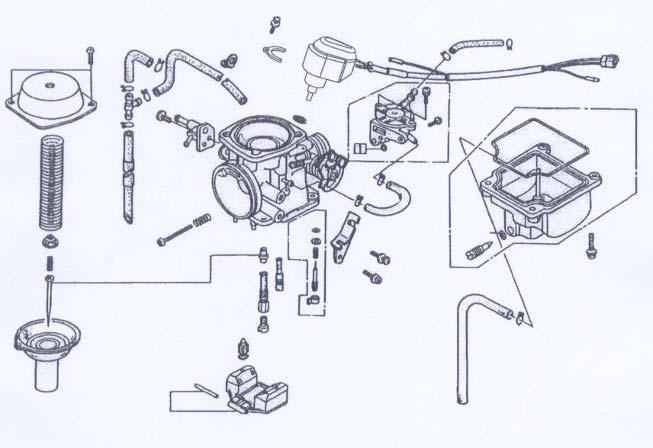
67 Carburetor 66

68 COOLING SYSTEM 67
69 68
70 69
71 70
72 71
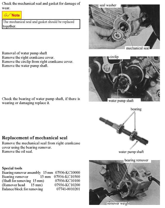
73 72

74 73
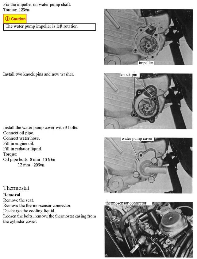
75 74
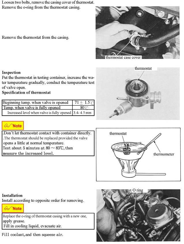
76 75
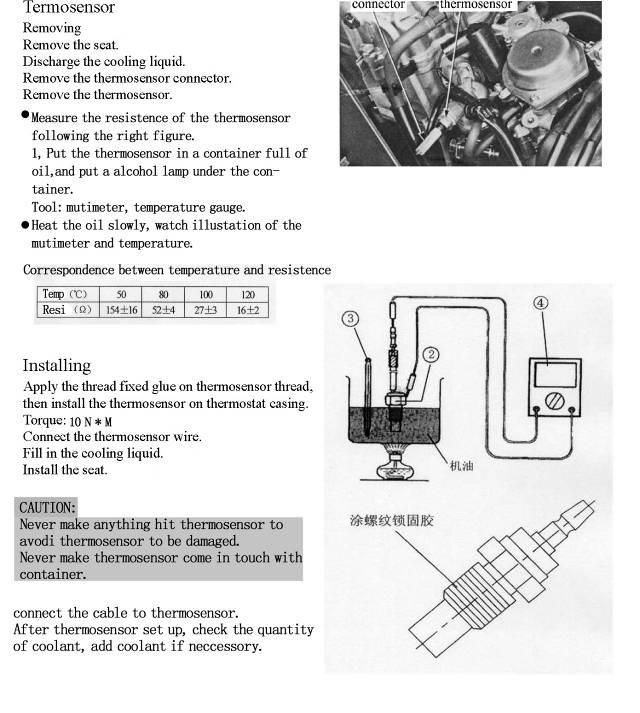
77 76
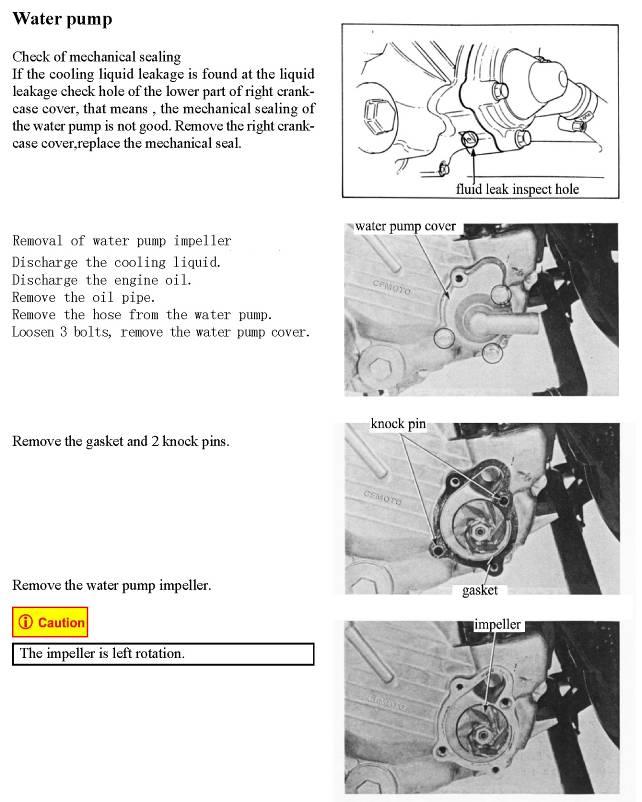
78 12N*m Left rotation Water pump 77
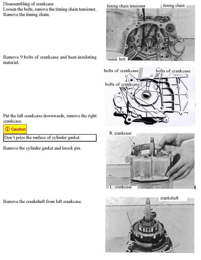
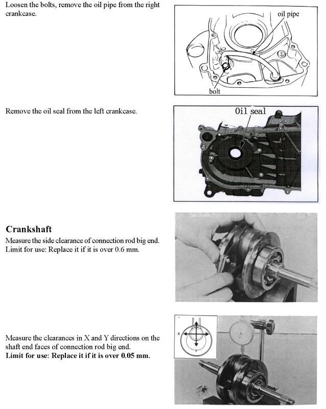
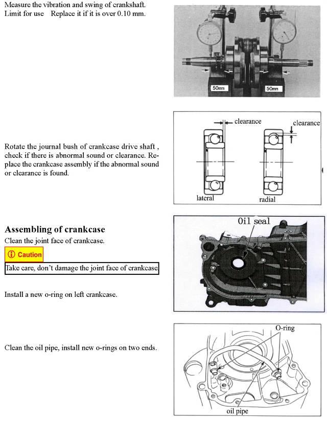
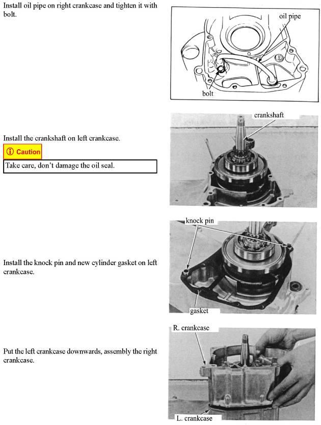
79 CRANK CASE 78
80 79
81 80
82 81
83 82
84 83
85 84
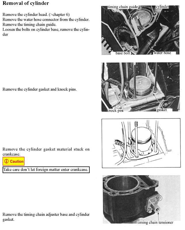
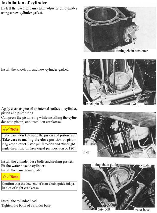
86 CYLINDER AND CYLINDER VALVE 85
87 86
88 87
89 88
90 89
91 90
92 91
93 92
94 93
95 94
96 95
97 96
98 97
99 98
100 99
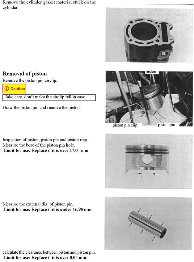
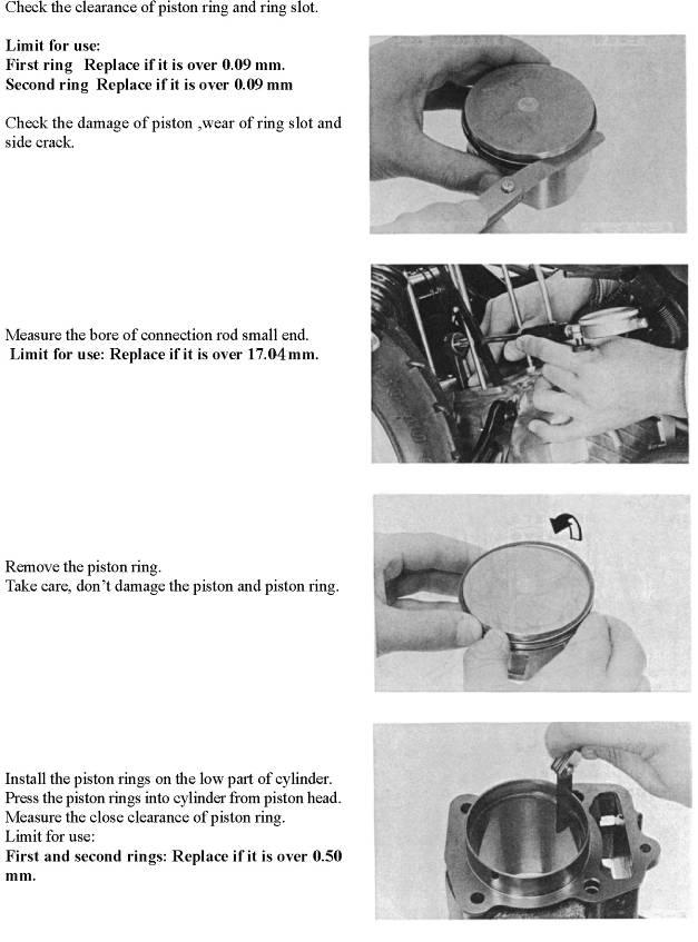
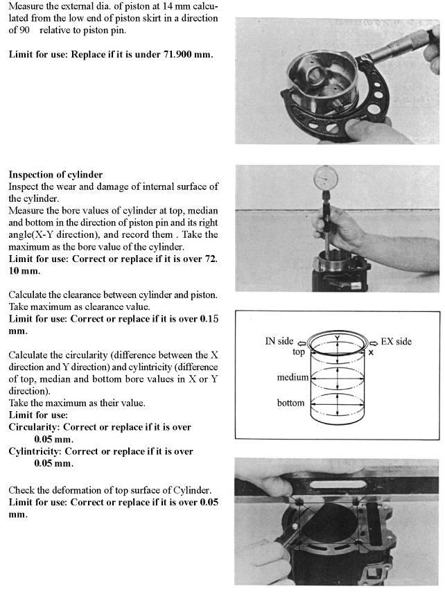
101 CYLINDER, PISTON 100
102 101
103 102
104 103
105 104
106 105
107 106
108 107
109 CTV 108
110 109
111 110
112 111
113 112
114 113
115 114
116 115
117 116
118 117

119 118
120 119
121 120
122 121
123 122
124 123
125 124
126 GEARBOX,GEAR SHIFT MECHANISM Precaution Recommended oil: 4 Stroke motorcycle SAE10W-30 or 4 trip motorcycle SAE20W-50. API classification SE or SF-class engine oil (chose the type of oil according the figure on page) Oil capacity: 0.85 L (when disassembly) 0.70 L (when replacement) Torque Gearbox bolts M5 5 N*m M6 10 N*m M 8 22 N*m Draining bolt 20 N*m Filling bolt 20 N*m Round bolt fixing driving angel gear 85 N*m Round bolt fixing driven angel gear 40 N*m Tools No. Tool specification use Remarks 1 Bearing-remover 12mm Remove bearing 6201 Work with 8,9 2 Bearing-remover 15mm Remove bearing 6202 Work with 8,9 4 Bearing-remover 17mm Remove bearing 6303 Work with 8,9 5 Bearing-remover 20mm Remove bearing 6304 Work with 8,9 6 Bearing-remover 22mm Remove the bearing on the left of main shaft Work with 8,9 7 Bearing-remover 25mm Remove bearing 6305 Work with 8,9 8 Bearing-remover handle 9 Balance block of Bearing-remover 10 Guide for press bearing 12mm Assembly bearing 6201 Work with Guide for pressing bearing 15mm Assembly bearing 6202 Work with Guide for pressing bearing 17mm Assembly bearing 6303 Work with Guide for pressing bearing 20mm Assembly bearing 6304 Work with Guide for pressing bearing 22mm assembly the bearing on the left of main shaft Work with Guide for press bearing 25mm Assembly bearing 6305 Work with Handle for pressing bearing 17 Hook wrench 34mm-36mm Remove or assembly round nut 18 Punch Riveting 125
127 Trouble shooting Engine can run vehicle can t move Damage of gearbox Failure of gear-shifting mechamism Abnormal sound when moving Wearing, sintering on gears, damage on the surface of gears. Wearing, loosening on bearings Wrong clearance of angel gears Gear position display don t work, gear jump. Failure of connector to gear position display Failure of connection between chip and display. Failure of gear-shifting limitation. Leaking of oil Over-quantity of oil. Wearing or damage of oil seal. 126

128 Disassembly 1. Remove left side cover. 2. Remove transmission, clutch,belt. 3. Unscrew the draining bolt to drain the oil. 4. Remove gear shifting arm. 5. Unscrew the gear shift limiting bolt. 6. Unscrew the bolt fixing sprocket cover, and remove the sprocket cover, driving sector gear and driven sector gear and so on. 7. Unscrew the bolt fixing the pressing-sprocket plate, and take off sprocket. 8. Unscrew the bolt fixing gear box cover, and take off the gear box cover. 9. Take off the main shaft comp, counter shaft comp, transition shaft comp, output shaft comp and gear-moved drum assy. 127
129 128
130 Inspection Check the surface of input main shaft to see if turn to blue, pitting, damage, wearing. Replace with a new one if any of the situations happen. Replace the seals with a new one after being removed anyway. Check if wearing or damage on counter shaft 1. Beak down the counter shaft according the right figure. 2. Measure the run out tolerance of the counter shaft with a dial indicator, replace with a new on if the tolerance is more than 0.03mm. 3. Check the surfaces of the gears to see if turn to blue, pitting, damage, over wearing, replace with a new one if any of them happen. 4. Check the clearance between shifting fork and gear: as the right figure, measure the clearance with a feeler. Replace shifting fork or gear if the clearance is more than 0.05mm. Standard clearance : 0.1~0.3mm 5. Measure the width of the groove for shifting fork with a slide caliper. 129
131 Inspection on gear-shift drum assembly 1. Break down the assembly according the right figure. 2. Check the drum, forks, fork pins to see if pitting, damage, wearing out. If that, replace with a new one. 3. Check to see if contacting chip deform, lack of the elastic force, if that, replace with a new one. 4. Measure the thickness of the shifting-fork. the standard thickness: 5.90~6.00mm. 5. Check these areas pointed by 1 and 2 to see if damage, bend. If that, replace with a new one. 130

132 Check the transition shaft to see if wearing out, damaged. 1. Break down the output driving shaft Comp. 2. Check to see if turning blue, pitting, damage, wearing out, if that, replace the part with a new one. Tool: circlip pliers Inspection on gear-shifting limiting bolt 1. Break down the limiting bolt Comp. 2. Check the wearing and damage on the ball, if any of them happen, replace a new ball. Check the wearing and damage on gear-shifting sector gear Comp. 1. Break down the Comp as the right figure. 2. Whenever remove the seal and the gasket, replace with a new one when put them back., at the same time, clean the surfaces going to be in contact. To be careful not to damage or scratch the surfaces. 3. Check the surfaces on gears and shaft to see if pitting, damage, wearing out. Replace with a new one if any of them is found. Check the gearbox cover to see if damaged, wearing out. 1. Check the bearing to see if it works well, if not, replace with a new one. 2. Check the points of contact on gears-display to see if rust, if that polish the surface with sandpapering. 3. Always use a bearing- remover when replacing bearing. Bearing remover Bearing remover unit 15: Bearing-remover 15 Bearing-remover handle Balance block of Bearing-remover Bearing remover unit 17: Bearing-remover 17 Bearing-remover handle Balance block of Bearing-remover 131


133 Bearing remover unit 20: Bearing-remover 20 Bearing-remover handle Balance block of Bearing-remover Bearing remover unit 12: Bearing-remover 12 Bearing-remover handle Balance block of Bearing-remover Check the bearings on the left case of gearbox 1. Check the bearing to see if it works well, if not, replace with a new one. 2. Always use a bearing- remover when replacing bearing. Bearing remover Bearing remover unit 15: Bearing-remover 15 Bearing-remover handle Balance block of Bearing-remover Bearing remover unit 22: Bearing-remover 22 Bearing-remover handle Balance block of Bearing-remover Bearing remover unit 20: Bearing-remover 20 Bearing-remover handle Balance block of Bearing-remover Bearing remover unit 12: Bearing-remover 12 Bearing-remover handle Balance block of Bearing-remover Inspection on output shaft Comp 1. Break down the output shaft Comp as the right figure. 2. Check to see if turning blue, pitting, damage, wearing out, if that, replaces the part with a new one. 132
 Apply the engine oil to the movable parts. 4) Apply the grease to the sealing parts, such as: seals, O rings. 5) Replace with a new one after the pats like oil seal, O ring are removed. 2.")
 Always use a special tool to push down the bearing.")
134 Assembly 1. The order of the assembly is contrary to the disassembly. Pay attention to the following tips: 1) Clean parts before installment. 2) Confirm there are no scratches on the surface of part. 3) Apply the engine oil to the movable parts. 4) Apply the grease to the sealing parts, such as: seals, O rings. 5) Replace with a new one after the pats like oil seal, O ring are removed. 2. If the bearings in the left case and gearbox cover need to be replaced. Pay attention to the following cautions: 1) Apply engine oil to the cylinders of bearing and case hole. 2) Always use a special tool to push down the bearing. Special tools: Guide for press bearing 25mm Guide for pressing bearing 15mm Guide for pressing bearing 12mm Guide for pressing bearing 22mm Guide for press bearing 17mm Handle for pressing bearing 3. Install main shaft 1) Apply engine oil on the surfaces which main shaft and bearing contact in. 2) Put the main shaft on to the left case. 133
135 4. Assembly output shaft Comp. 1) Put the gear (2) on to the output shaft after put the circlip (3) on to the output shaft(4), and put the washer (1) on to the output shaft(4), 2) Put the parts (5, 6, and 7) on to the output shaft after the gear box cover is put back. General tool: Shaft circlip pliers 134
136 5. Assembly counter shaft Comp. 1) Put all the parts on to the counter shaft in a contrary order of disassembly. 2) Apply engine oil on every needle bearing. 3) After assembly, check to see if the driven gear, reverse driven gear, low speed driven gear can run freely. General tool: Shaft circlip pliers 6. Assembly gear shift drum unit. 1) Put all the parts on to gear shift drum with contrary order of disassembly. 2) Apply engine oil in the holes in shift forks and pin holes 3) If the touch-chip of gear position display or the circlips of shift forks deform, replace with a new one. 4) After assembly, turn the forks to make sure that they can run smoothly. General tool: Nipper pliers, flat screwdriver Assembly transition shaft Comp Assemblies the transition shaft comp with reversing the order of disassembly. General tool: Shaft circlip pliers 135
 Assemble counter shaft Comp and gear shift drum Comp well, Make sure the gear shifting forks go into the groove on slide bushing on counter shaft.")
137 9. Assembly 1) Apply engine oil on the matching surfaces on both main shaft and bearing, then install the main shaft in to left case. 2) Assemble counter shaft Comp and gear shift drum Comp well, Make sure the gear shifting forks go into the groove on slide bushing on counter shaft. 3) Put the assembly assembled by last step in to the related holes in left case. 4) Put the output driving shaft Comp and transition shaft Comp in to the related holes in the left case. 5) Apply engine oil on the gear s surfaces, matching surfaces and bearing. 6) Turn the output shaft with your left hand while turn the gear shift drum with your right hand, check to see if shift gears easily and smoothly, and the gears can engage each other fully. 7) Smear the seal glue on to the surfaces is going to be touched with gasket uniformly. 8) Knock down pins.(2pieces, 10x14 ). 136
 Install output sprocket, pressing plate, bolts.")
 Install sprocket pin and sprocket cover. a. Put the knock pin (11, 2pcs) in to the holes in the sprocket cover.")

138 9) Put on gasket. 10) Assemble the gear box cover Comp, install the parts 5,6,7 in to the related holes respectively. Torque: 22 N*m 11) Install output sprocket, pressing plate, bolts. Torque: 10N*m 12) Turn the gear shifting drum to the natural position, put on driving sector gear Comp, driven sector gear Comp and sprocket. Align the marks on both driving sector gear and driven sector gear. 13) Install sprocket pin and sprocket cover. a. Put the knock pin (11, 2pcs) in to the holes in the sprocket cover. b. Put on sprocket and sprocket cover. c. Put the parts 14,15 into the related holes. Torque: 10N*m. d. Install the part 16, use a special tool to push the seal down, and smear some grease on the lip of seal. 14) Put the draining bolt (4) with washer (3) into the related hole. Torque: 20N*m 15) Install seal, sector gear house cover, gear shifting arm Comp. Torque for bolt of M6: 10N*m. Smear some grease on the lip of seal. 137
 Install")
 Fill oil through the fill bolt hole, and then screw the filling")

139 16) Install seal of main shaft, transmission, clutch and belt. Torque: Nut of clutch: 49N*m Nut of transmission: 78N*m 17) Install left cover. 18) Fill oil through the fill bolt hole, and then screw the filling bolt. Put the engine into a horizontal position. Fill in the oil specified for 4 strokes motor. Fill in the oil to the neck of filling bolt hole. After fill in oil, install O-ring and screw the filling bolt. 138
140 Gear box cover Gear shifting mechanism 139

141 Speed reducing gear 140
142 MAGNETO, STARTER, CLUTCH AND OIL PUMP 141
143 142
144 143
145 144
146 145
147 146
148 147
149 148
150 149
151 150
152 151
153 152
154 153
155 CHASSIS REPAIR A. Front Wheel Replacement Do not disassemble the castle nuts when you replace the front wheels. It is only necessary to tighten the nuts so that the wheel turns freely on the axle with minimum end play. (See Fig. 16) Tighten the nuts after replacing the wheels. Castle nuts Torque: 180±5 N.M Wheel nuts Torque: 70±5 N.M Figure 16 B. Rear Wheel Replacement Do not disassemble the castle nuts when you replace the rear wheels. It is only necessary to tighten the nuts so that the wheel turns freely on the axle with minimum endplay. (See Fig. 17) Tighten the nuts and put on the cotter Pin after replacing the wheels. Castle nuts Torque: 180±5 N.M Wheel nuts Torque: 70±5 N.M Figure 17 C. Front Wheel Alignment a. The front wheels should be toe-in from 1/8 to 1/4. To check for alignment, measure distance A and B between the centerline (CL) of the wheels. The proper toe-in dimension A should be 1/8-1/4 greater than dimension B. b. To adjust the alignments, loose the lock nuts on both sides of Front Tie Rods. To make Dimension B smaller, scare the rod to the left. Adjust the rod to right direction to make Dimension B larger. After adjusted to desired length, tighten the lock nut against the rod end. Recheck the dimensions for proper alignment. 154
156 G WIRING DIAGRAM Alternator Thermometer swich (88 o C) H-gear sensor L-gear sensor N-gear sensor Reverse sensor Rectifier, regulator 3 ~ G Battery 12V 9Ah Ignition switch OFF ON Start M Start motor 12V 600W Fuse box Ignition coil Flasher 12V 45W High beam switch blue Dipped beam switch green Turn signal switch Charge indication red Reverse indication yellow Horn button Brakes light switch ON ON ON OFF tc BP v n' t C v tc H L N R Speed sensor water temperature sensor Thermometer swich (102 o C) Radiator fan 12V 10A Horn R L R L Headlight 12V 35/35W Tail lamp/ the brake light 12V 5/21W Turning signal, before R 12V 10W Turning signal, Rear R 12V 10W Turning signal, before L 12V 10W Turning signal, Rear L 12V 10W L R 10A 5A 5A 5A 5A 15A 10A 12V U S U R Start relay Speed sensor Spot light switch BR RG Y NB P O RW RY NB UW NR RY Speed meter Rev meter water temperature meter Voltage meter v UR RW UW UY RB sw PY RW Wire's colour symbol RS---red/grey B---black R---red U---blue RU---red/blue P---purple S---grey W---white YG---yellow/green L---Cambridge blue N---brown K---pink NB---brown/black NR---brown/red UW---blue/white RB---red/black GY---green/yellow SB---grey/black BR---black/red Y---yellow WG---white/green GB---green/black WR---white/red BW---black/white O--Orange Spot light 3x (12V 21W) NR K k 155
157 PARTS MANUAL 1 CRANKCASE ASSY. No. ERP CODE P/N ENGLISH Qty 1 02.DLJ.172MM-C MM-C LEFT CRANK CASE ASSY DLJ.172MM-C MM-C RIGHT CRANK CASE ASSY DLJ.172MM MM SEAL 28X40X DLJ.172MM MM INNER OIL PIPE SEAL RING DLJ.172MM MM CYLINGDER STUD A DLJ.152MI MI LOCATING PIN Φ10x DLJ.172MM MM CYLINGDER STUD B DLJ.172MM-B MM-B CRANK CASE SEAL WASHER DLJ.172MM MM INNER OIL PIPE DLJ.152MI MI BOLT M6X DLJ.152MI MI BOLT M6X DLJ.1P52MI P52MI BOLT M6X DLJ.1P52MI-A P52MI-A BOLT M6X DLJ.152MI MI OUTER SLEEVE.EAR DLJ.152MI MI "O" RING FOR SEAL DLJ.152MI MI INNER SLEEVE.EAR DLJ.GB/T GB/T BEARING

158 1 CRANKCASE ASSY. No. ERP CODE P/N ENGLISH Qty DLJ.172MM MM BALL BEARING 22X50X DLJ.GB/T GB/T FB33X35X5 FB33X35X5 OIL SEAL FB 33X35X DLJ.GB/T GB/T BEARING DLJ.GB/T GB/T RS 6202-RS BEARING 6202-RS DLJ.172MM-B MM-B HOLLOW BOLT M14X DLJ.CF CF WASHER 14.4X22X DLJ.CF CF SPACER SPRING DLJ.GB/T /8 GB/T /8 STEEL BALL 1 "O" RING FOR 02.DLJ.152MI MI SEAL13.5X DLJ.172MM-B MM-B ODOMETER SENSOR DLJ.172MM-B MM-B SEAL CAP DLJ.152MI MI BOLT M6X
159 2 SIDE COVER ASSY.L No. ERP CODE P/N ENGLISH Qty 1 02.DLJ.172MM-B MM-B LEFT SIDE COVER DLJ.172MM-B MM-B AIR DAMPER DLJ.GB/T M6X12 GB/T M6X12 SCREW DLJ.172MM-B MM-B BOLT DLJ.152MI MI BOLT DLJ.152MI MI LOCATING PIN Φ10x DLJ.172MM-B LEFT SIDE COVER SEAL 172MM-B WASHER DLJ.152MI MI BOLT 1 158

160 3 RIGHT COVER ASSY No ERP CODE P/N ENGLISH Qty 1 02.DLJ.172MM MM CYLINDER HEAD COVER AIR PIPE DLJ.172MM MM RIGHT SIDE COVER BREATH PIPE DLJ.172MM MM AIR FILTER BREATH PIPE DLJ.172MM MM BREATH PIPE CLAMP DLJ.172MM MM RIGHT SIDE COVER DLJ.172MM MM CABLE PRESS PLATE DLJ.172MM MM RIGHT SIDE COVER SEAL WASHER DLJ.172MM MM OIL FILTER CAP DLJ.152MI MI OIL FILTER CORE DLJ.172MM MM SPRING DLJ.172MM MM ENGINE OIL METER DLJ.172MM MM WAY DLJ.152MI MI UPPER OBSERVATION HOLE CAP DLJ.172MM MM BOLT DLJ.172MM MM "O" RING 30X DLJ.152MI MI SEAL RING.CAP DLJ.172MM MM "O" RING 18X DLJ.172MM MM OUTLET BOLT DLJ.152MI MI WASHER
161 3 RIGHT COVER ASSY No. ERP CODE P/N ENGLISH Qty DLJ.152MI MI LOCATING PIN Φ8x DLJ.QC/T A10 QC/T A10 CLAMP DLJ.QC/T A12 QC/T A12 CLAMP DLJ.172MM MM BREATH FAUCET DLJ.172MM WATER OUTLET 172MM FAUCET DLJ.152MI MI BOLT M6X DLJ.172MM MM PROTECTION PIPE DLJ.152MI MI BOLT M6X DLJ.1P52MI P52MI BOLT M6X
162 4 CYLINGDER HEAD CASEING ASSY No. ERP CODE P/N ENGLISH Qty 1 02.DLJ.172MM MM OIL PIPE CLAMP DLJ.172MM MM CYLINDER HEAD COVER DLJ.172MM MM STOP PLATE DLJ.152MI MI SEAL WASHER DLJ.172MM MM SWING ARM.INLET AXIS DLJ.172MM MM SWING ARM.OUTLET AXIS DLJ.172MM MM OUTER ENGINE OIL PIPE DLJ.152MI MI OIL PIPE RUBBER RING DLJ.172MM MM OIL PIPE MOUNT DLJ.152MI MI SHOCK ABSORBER RUBBER STRIP DLJ.152MI MI REAMED BOLT A M8X DLJ.152MI MI REAMED BOLT M12X DLJ.152MI MI REAMED BOLT M8X DLJ.152MI MI UPPER OBSERVATION HOLE CAP DLJ.152MI MI WASHER DLJ.152MI MI EAR WASHER DLJ.152MI MI WASHER DLJ.152MI MI UPPER OBSERVATION HOLE SEAL DLJ.152MI MI SWING ARM AXIS SEAL RING DLJ.GB/T M5X16- GB/T M D Cr 5X16-D Cr CRUCIFORM SLOT SCREW DLJ.GB/T D Cr GB/T D Cr SMALL WASHER DLJ.152MI MI LOCATION PIN Φ10X DLJ.GB/T9074, GB/T M6X12 8 BOLT M6X
163 4 CYLINGDER HEAD CASEING ASSY No. ERP CODE P/N ENGLISH Qty DLJ.BOLTM6X25 BOLTM6X25 BOLT M6X DLJ.152MI MI BOLT M6X DLJ.152MI MI BOLT M6X DLJ.172MM MM SHOCK ABSORBER SLEEVE DLJ.172MM MM BREATH PIPE FAUCET DLJ.172MM MM AIR FILTER MOUNT DLJ.172MM MM BLOCKING 1 162
164 5 CYLINGDER HEAD ASSY No. ERP CODE P/N ENGLISH Qty 1 02.DLJ.172MM MM CYLINDER HEAD DLJ.172MM MM EXHAUST FLANGE DLJ.152MI MI BEARING COVE.CAM AXIS DLJ.172MM MM EXHAUST NUT DLJ.172MM MM CYLINDER HEAD SEAL WASHER DLJ.172MM MM CARBURETOR SEAT UNIT DLJ.172MM MM AIR INLET PIPE CLAMP UNIT DLJ.152MI MI THERMOSTAT DLJ.152MI MI UPPER THERMOSTAT SHELL DLJ.152MI MI CARBURETOR RUBBER PIPE DLJ.172MM MM LOWER THERMOSTAT SHELL DLJ.172MM MM SPARK PLUG DLJ.152MI MI BOLT M6X DLJ.172MM MM BREATH SEAL WASHER DLJ.152MI MI WATER TEMP SENSOR DLJ.GB/T GB/T M6X18-D M6X18-D Cr Cr SOCKET HEAD SCREW DLJ.172MM MM DOUBLE-SCREW BOLT DLJ.152MI MI WASHER DLJ.152MI MI CAP NUT M DLJ.152MI MI "O" RING 14.8X DLJ.172MM MM "O" RING 31X DLJ.152MI MI BOLT M6X DLJ.152MI MI LOCATION PIN Φ10X
165 5 CYLINGDER HEAD ASSY No. ERP CODE P/N ENGLISH Qty DLJ.QC/T A6,5 QC/T A6.5 STEEL RING CLAMP DLJ.152MI MI BOLT M6X DLJ.152MI MI BOLT M6X DLJ.152MI MI CARBURETORS BREATHE PIPE DLJ.GB/T D Cr GB/T D Cr SMALL WASHER DLJ.152MI MI SCREW BLOCKAGE 1 164
166 6 CYLINGER BODY ASSY No. ERP CODE P/N ENGLISH Qty 1 02.DLJ.172MM MM CYLINDER DLJ.172MM MM CYLINDER SEAL WASHER DLJ.152MI MI TENSIONER UNIT DLJ.152MI MI SPRING SEAT BOLT DLJ.152MI MI TENSIONER SPRING DLJ.152MI TENSIONER SEAL 152MI WASHER DLJ.172MM WATER INLET RUBBER 172MM PIPE DLJ.172MM MM WATER PIPE JACKET DLJ.QC/T B24 QC/T B24 STEEL BAND CLAMP DLJ.152MI MI WASHER DLJ.GB/T D ZN GB/T D ZN SMALL WASHER DLJ.152MI MI LOCATION PIN Φ10X DLJ.152MI MI BOLT M6X DLJ.152MI MI BOLT M6X
167 7 TIMING CHAIN No. ERP CODE P/N ENGLISH Qty 1 02.DLJ.172MM MM CHAIN UNIT DLJ.172MM MM TENSION PLATE DLJ.172MM CHAIN GUIDE 172MM PLATE DLJ.GB D Zn GB D Zn BIG WASHER DLJ.GB/T M6X12-D Zn GB/T M6X12-D Zn BOLT 1 166
168 8 MAGNETOR ASSY No. ERP CODE P/N ENGLISH Qty 1 02.DLJ.172MM MM FREE-WHEELING CLUTCH DLJ.172MM MM TRIGGER COIL DLJ.172MM MM CABLE PRESS BAND DLJ.172MM MM FREE-WHEELING DLJ.172MM MM STATOR UNIT DLJ.GB/T70, M8X18 GB/T M8X18 SOCKET HEAD SCREW DLJ.172MM MM NUT M16X DLJ.172MM MM WASHER16.3X30X DLJ.152MI MI BOLT M5X DLJ.152MI MI BOLT M6X
169 9 ADMISSION MACHANISM No. ERP CODE P/N ENGLISH Qty 1 152MI MI VALVE ROD SEAL MM MM CAM UNIT MI MI SWING ARM MM MM INTAKE VALVE MM MM EXHAUST VALVE MM MM OUTTER VALVE SPRING MM MM INNER VALVE SPRING MI MI VALVE SPRING PAN MI MI VALVE SPRING SEAT MI MI VALVE CLAMP 4 11 NTN: NTN: BALL BEARING 2 12 GB894.A GB894.A RETAINER RING AXIS MM MM CHAIN PULLY MI MM CAM AXIS 1 168
170 10 CRANK LINK LEVER & PISTON No. ERP CODE P/N ENGLISH Qty 1 02.DLJ.172MM-A MM-A CRANK LINK UNIT 1 02.DLJ.172MM MM PISTON RING DLJ.172MM MM PISTON RING 1 02.DLJ.172MM MM OIL RING DLJ.172MM MM PISTON DLJ.172MM MM PISTON PIN DLJ.152MI MI OIL CHANNEL JOINT DLJ.152MI MI JOINT SPRING DLJ.152MI MI WOODRUFF KEY DLJ.172MM MM PISTON PIN STOP RING DLJ.GB/T X14 GB/T X14 PIN 1 169
171 11 SPEED CHANGER. No. ERP CODE P/N ENGLISH Qty 1 02.DLJ.172MM MM NUT M14X DLJ.172MM MM WASHER14.5X DLJ.172MM-A MM-A DRIVE WHEEL PAN DLJ.172MM-A MM-A DRIVE WHEEL PAN SLEEVE DLJ.172MM-A MM-A MOVABLE DRIVE PAN DLJ.172MM-A MM-A OFFCENTER ROLLER DLJ.172MM-A MM-A SLIDING BLOCK DLJ.172MM-A MM-A PUSH PAN 1 170
172 12 CLUTCH ASSY No. ERP CODE P/N ENGLISH Qty 1 02.DLJ.172MM MM BOLT M12X DLJ.172MM-A MM-A OUTTER WHEEL DISC DLJ.172MM MM THIN NUT M30X DLJ.172MM-A MM-A DRIVE PAN UNIT 1 5 DAMPING RUBBER 02.DLJ.172MM-A MM-A BLOCK DLJ.172MM-A MM-A CLUTCH BLOCK DLJ.172MM-A MM-A RELEASE SPRING DLJ.172MM-A MM-A SIDE PAN DLJ.GB/T GB/T SPLIT WASHER DLJ.172MM MM NEEDLE BEARING DLJ.GB/T893, GB/T HOLE RETAINER RING DLJ.GB/T GB/T BEARING DLJ.172MM-A MM-A DRIVEN PAN UNIT DLJ.172MM-A MM-A GALLOWS ROLL DLJ.172MM-A DRIVEN PAN GREASE 172MM-A SEAL DLJ.172MM-A MM-A MOVABLE DRIVEN PAN DLJ.GB/T3452, ,2X1,8 GB/T X1.8 "O" SEAL RING DLJ.172MM-A MM-A SEAL BUSHING DLJ.172MM-A MM-A CLUTCH SPING DLJ.172MM-A MM-A SLEEVE DLJ.172MM-A MM-A GUIDE PIN DLJ.172MM-B MM-B COG BELT 1 171

173 13 GEARBOX COVER ASSY No. ERP CODE P/N ENGLISH Qty 1 02.DLJ.172MM-C MM-C GEARBOX COVER DLJ.172MM-C MM-C GEAR BOX PAPER WASHER DLJ.172MM MM BOLT M12X1.5.OIL OUTLET DLJ.152MI MI WASHER DLJ.172MM-B MM-B SHIFT DISPLAY SWITCH DLJ.GB/T RS GB/T RS BALL BEARING DLJ.GB/T GB/T BALL BEARING DLJ.GB/T GB/T BALL BEARING DLJ.GB/T RS GB/T RS BALL BEARING DLJ.172MM-B MM-B BOLT M8X DLJ.172MM-B MM-B BOLT M8X DLJ.1P52MI-A P52MI-A BOLT M8X DLJ.CF CF "O" RING 19X DLJ.CF CF OIL INLET BOLT DLJ.172MM-C MM-C OIL SEAL 32X62X DLJ.CF CF AIR PIPE JOINT DLJ.152MI MI LOCATION PIN Φ8X DLJ.172MM-C MM-C PAPER WASHER DLJ.172MM-C MM-C CHAIN PULLY COVER DLJ.GB M6X40-D Cr GB M6X40-D Cr BOLT DLJ.152MI MI BOLT M6X DLJ.CF CF OIL SEAL SD 15X25X DLJ.172MM-B MM-B OIL STOP CHIP DLJ.GB/T GB/T SCREW M4X

174 14 TRANSMISSION GEAR ASSY No. ERP CODE P/N ENGLISH Qty 1 02.DLJ.172MM-B MM-B TRANSITION GEARS ASSY DLJ.GB/T894, GB/T RETAINER RING DLJ.172MM-B MM-B TRANSITION GEAR DLJ.172MM-B MM-B TRANSITON GEAR-AXIS DLJ.172MM-B MM-B MAIN AXIS DLJ.172MM-B MM-B SECONDARY AXIS ASSY DLJ.172MM-B MM-B WASHER.15X28X DLJ.172MM-B HIGH SPEED DRIVING 172MM-B GEAR DLJ.NTN:K16X20X10 NTN: K16X20X10 NEEDLE BEARING DLJ.172MM-B MM-B SHIFT SLIDING SLEEVE DLJ.172MM-B MM-B SECONDARY AXIS DLJ.172MM-B MM-B WASHER 24X33X DLJ.GB/T894, GB/T CIRCLIP.AXIS DLJ.K24X28X10 K24X28X10 NEEDLE BEARING DLJ.172MM-B MM-B REVERSE DRIVEN GEAR DLJ.172MM-B MM-B OUTPUT DRIVEN GEAR DLJ.172MM-B MM-B LOW SPEED DRIVEN GEAR DLJ.172MM-C MM-C OUTPUT AXIS ASSY DLJ.172MM-C MM-C WASHER 20X32X DLJ.172MM-C MM-C OUTPUT DRIVEN GEAR 1 173
175 14 TRANSMISSION GEAR ASSY No. ERP CODE P/N ENGLISH Qty DLJ.CF CF RETAINER RING.AXIS DLJ.172MM-C MM-C OUTPUT AXIS DN A DN A CHAIN PULLEY DN CHAIN PULLEY PRESS DN PLATE DLJ.172MM-C MM-C BOTL M6X DLJ.172MM-B MM-B WASHER 16X28X
176 15 GEAR SHIFT MACHANISM No. ERP CODE P/N ENGLISH Qty 1 02.DLJ.172MM-B MM-B SHIFT DRUM ASSY DLJ.172MM-B MM-B SHIFT YOKE DLJ.172MM-B MM-B SHIFT YOKE PIN DLJ.172MM-B MM-B SHIFT YOKE PIN SNAP RING DLJ.172MM-B MM-B SHIFT DRUM DLJ.172MM-B MM-B SPEED DISPLAY TOUCH CHIP DLJ.CF DRIVEN SECTOR GEAR CF WASHER DLJ.CF CF DRIVING SHIFT SECTION GEAR DLJ.CF CF WASHER 13.5X22X DLJ.CF DRIVING SHIFT SECTOR GEAR CF AXIS DLJ.CF CF DRIVEN SECTOR GEAR SPRING DLJ.CF CF WASHER 6.6X20X DLJ.151MI MI BOLT M6X DLJ.151MI MI BOLT M6X DLJ.172MM-C DRIVE SHIFT SECTOR GEAR 172MM-C COMP DLJ.172MM-B MM-B SHIFT AXIS DLJ.172MM-B MM-B SHIFT PRESS SPRING DLJ.172MM-B MM-B SHIFT PRESS BUSHING 1 175
177 16 ENGINE OIL PUMP ASSY No. ERP CODE P/N ENGLISH Qty 1 02.DLJ.151MI MI OIL PUMP ASSY DLJ.151MI MI OIL PUMP BODY DLJ.151MI MI OIL PUMP COVER DLJ.151MI MI OIL PUMP AXIS DLJ.151MI MI OIL PUMP CHAIN PULLEY DLJ.151MI MI CHAIN.OIL PUMP DLJ.151MI MI INNER ROTOR.OIL PUMP DLJ.151MI MI OUTTER ROTOR.OIL PUMP DLJ.151MI OIL PUMP SPACER PLATE 151MI A DLJ.151MI OIL PUMP SPACER PLATE 151MI B DLJ.GB M3X12 GB M3X12 SCREW DLJ.151MI MI LOCATION PIN 4X DLJ.GB894, GB RETAINER RING.AXIS DLJ.151MI MI BOLT M6X DLJ.151MI MI BOLT M6X
178 17 COOLANT PUMP ASSY No. ERP CODE P/N ENGLISH Qty 1 02.DLJ.172MM MM WATER PUMP IMPELLER DLJ.152MI MI WATER SEAL ASSY DLJ.172MM MM WATER PUMP COVER DLJ.172MM MM COVER SEAL WASHER DLJ.172MM MM WATER PUMP AXIS DLJ.152MI MI BOLT M6X DLJ.152MI MI BOLT M6X DLJ.GB/T893, GB/T HOLE RETAINER RING DLJ.152MI MI WASHER.7.5X13X DLJ.152MI MI WASHER.6X12X DLJ.NTN:6800 NTN: 6800 NEEDLE BEARING DLJ.172MM MM GREASE SEAL 10X20X DLJ.152MI MI LOCATION PIN Φ8X
179 18 ELECTRIC STARTER ASSY No. ERP CODE P/N ENGLISH Qty 1 02.DLJ.172MM MM DUPLICATE GEAR AXIS DLJ.172MM MM DRIVEN GEAR COMP DLJ.172MM MM DUPLICATE GEAR COMP DLJ.172MM MM MOUNTING PLATE DLJ.172MM MM STARTER COMP DLJ.152MI MI BOLT M6X DLJ.172MM MM BOLT M6X

180 19 CARBURETOR ASSY No. ERP CODE P/N ENGLISH Qty 1 02.DLJ.172MM MM CARBURETOR ASSY 1 179
181 20 FRAME & FUEL TANK & RADIATOR 20 FRAME&FUEL TANK&RADIATOR
182 20 FRAME&FUEL TANK&RADIATOR NO. ERP CODE PART NO. DESCRIPTION Q'TY 1 02.DN DN MAIN FRAM (OPTION) DN DN COVER.FR DN DN LEFT SPORT WING(OPTION) DN DN LOWER SPORT WING(OPTION) DN DN UPPER SPORT WING(OPTION) M12X1,25X65/ M12x1.25x65 FLANGE BOLT M12X1.25X D D NYLON BUSHING M12X1,5/05 SJ2842-M12x1.5 FLANGE NUT M DN A DN A RIGHT PROTECTIVE BAR M10X1,25X20/ M10X1.25X20 FLANGE BOLT M10X1.25X M10X1,25/05 SJ2842-M10x1.25 FLANGE NUT M M10X1,25X65/ M10X1.25X65 FLANGE BOLT M10X1.25X DN DN ARC CUSHION \U DN DN REINFORCED BAR M8X20/ M8X20 FLANGE BOLT M8X D D WATER TANK.GK D D WATER TANK CAP.GK ,1-M8/ M8 FLANGE LOCK NUT M DN DN TOP PROTECTIVE BAR DN DN TOP PROTECTIVE BAR DI DI RADIATOR SAFETY COVER M8X30/ M8X30 FLANGE BOLT M8X DN DN RADIATOR SUPPORT JD JD RADIATOR RUBBER BUSHING D D RADIATOR CAPRADIATOR DI DI RADIATOR D D ACT(ACTIVATED CARBON D D BLOCK SHEET.ACT D D SUPPORT.ACT ,1-M6/ M6 FLANGE LOCK NUT M M6X20/ M6X20 FLANGE BOLT M6X DN A DN A LEFT PROTECTIVE BAR DN DN INLET PIPE.ACT JD JD FUEL TANK CAP DN DN FUEL TANK M8X20/ M8X20 FLANGE BOLT M8X20F M8/05 SJ2842-M8 FLANGE NUT M8F JD JD FUEL SWITCHF DN DN FUEL PIPE DS DS GAS FILTER DN DN FUEL PIPE DN A DN A SHIFT COVER D D SEAL CUSHING.WATER TANK JD JD RUBBER WASHER DN DN CLAMP 1.FUEL FILTER DN DN PROTECTIVE SPRING1.FUEL DN DN CLAMP 2.FUEL FILTER DN DN PROTECTIVE SPRING 2.FUEL 1 181
183 20 ALUMINIUM BAFFLE
184 20 ALUMINIUM BAFFLE NO. ERP CODE PART NO. DESCRIPTION Q'TY 1 02.DNB DNB MAIN FRAME DNB DNB LEFT SIDE BAFFLE DNB DNB BAFFLE UNDER SEATS DNB DNB BAFFLE UNDER FOOT DNB DNB FRONT LOWER BAFFLE DNB DNB RIGHT SIDE BAFFLE DNB DNB CONSOLE PLATE DNB DNB WING BOX LS LS LOCK ON WING BOX 1 183
185 21 FRONT SUSPENSION 21 FRONT SUSPENSION
186 21 FRONT SUSPENSION NO. ERP CODE PART NO. DESCRIPTION Q'TY 1 02.DN DN RIGHT LOWER A-ARM DN DN RIGHT KNUCKLE DN DN BRAKE CLIPPER DN DN RIGHT UPPER A-ARM M14X1,5X90/ M14X1.5X90 FLANGE BOLT M14X1.5X DN DN LEFT UPPER A-ARM ,1-GE20C GE20C JOINT BEARING GE20C ,2-φ φ35 HOLE RETAINOR RING DN DN SPACER.GE20C M14/05 SJ2842-M14 FLANGE NUT M14x M14X1,5X60/ M14X1.5X60 FLANGE BOLT M14X1.5X ,1-POSA14X2, POSA14x2.0 ROD END BEARING DN DN ROD END BEARING SPACER ,1-M14X1,5-R/ M14x1.5-R THIN NUT M DN DN LEFT UPPER A-ARM M12X1,5/05 SJ2842-M12X1.5 FLANGE NUT M12X DN DN SHOCK ABSORBOR SPACER M12X1,5X170/ M12X1.5X170 FLANGE BOLT M12X1.5X DN DN FR SHOCK ABSORBOR M12X1,5X60/ M12X1.5X60 FLANGE BOLT M14X1.5X M14X1,5X80/ M14X1.5X80 FLANGE BOLT M14X1.5X DN DN LEFT KNUCKLE M8X20/ M8x20 FLANGE BOLT M8X DN DN BRAKE CLIPPER DN DN FRONT WHEEL BUSHING FB28X47X FB28x47x7 GREASE SEAL FB47X28X BALL BEARING JD JD FRONT WHEEL BUSHING JD JD FRONT BRAKE DISC DS DS FRONT WHEEL KNURLED BOLT JD EU JD EU BEARING HUB BALL BEARING FB25X40X FB25x40x6 GREASE SEAL FB40X25X JD JD SMALL SPACER D D REAR WHEEL AXLE WASHER φ16/05 93-φ16 SPRING WASHER M16/ M16 SLOTTED NUT M φ4X40/05 91-φ4x40 COTTER PIN 4x DN DN TYRE 21X JD JD RIM 10X
187 21 FRONT SUSPENSION
188 21 FRONT SUSPENSION NO. ERP CODE PART NO. DESCRIPTION Q'TY φ10/05 93-φ10 SPRING WASHER φ10X20X2/05 95-φ10x20x2 PLAIN WASHER M10X1, M10x1.25 CAPPED NUT M10X M12X1,5X80/ M12X1.5X80 FLANGE BOLT M12X1.5X D D ROD END BEARING D D SPACER φ12.tie ROD DN DN FRACTION PLATE DN DN FRACTION PLATE DN DN BRAKE CLIPPER SPRING PLATE DN DN BRAKE CLIPPER SPRING PLATE JD JD FRONT WHEEL HUB COVER 2 187
189 STEERING&THROTTLE&BRAKE&SHIFT STEERING&THROTTLE&BRAKE&SHIFT
190 22 STEERING&THROTTLE&BRAKE&SHIFT No. ERP CODE PART NO. DESCRIPTION Q'TY 1 02.D D ROD END BEARING POSA12L ,1-M12-L/ M12-L THIN NUT M12L DN DN TIE ROD ,1-M12X80/ M12x80 BOLT M12X D D REINFORCED SHEET.TIE ROD D D TIE ROD SPACER D D DUST GUARD PLATE D D TIE ROD SUPPORT ,1-M M8 GREASE CUP M8X D D STEERING BOX CASE D D STEERING RACK D D BUSH BEARING14c7x18x D D STEERING BOX COVER PLATE D D STEERING GEAR SHAFT D D BALL BEARING 20x42x M10X30/ M10X30 FLANGE BOLT M10x D D BEARING STOP PLATE M6X25/ M6x25 FLANGE BOLT M6x M8X30/ M8x30 BOLT M8X φ8/05 93-φ8 SPRING WASHER DN DN SLIP UNIVERSAL JOINT SHAFT DN DN SPRING PLATE DN DN SLIP UNIVERSAL JOINT SLEEVE ,2-φ φ26 CIRCLIP FOR HOLE BALL BEARING DN DN STEERING COLUMN SLEEVE BALL BEARING ,2-φ φ28 CIRCLIP FOR HOLE DN DN STEERING COLUMN SHAFT ,1-M8/ M8 FLANGE LOCK NUT M TR TR STEERING WHEEL ,2-M6X25/ M6x25 INNER SUNK SCREW M6x TR TR PLASTIC COVER M4/05 41-M4 CROSS PANHEAD SCREW M4x φ4/05 93-φ4 SPRING WASHER DN DN MAIN BRAKE PISTON ,1-M8/ M8 FLANGE LOCK NUT M DN DN BRAKE PUSH POLE ,1-M8-R/ M8-R THIN NUT M M8X30/ M8X30 FLANGE BOLT M8x D D "T" BLOCK φ3X30/05 91-φ3x30 COTTER PIN 3x φ10X20X2/05 95-φ10X20X2 PLAIN WASHER DN DN BRAKE BOARD FOOT PIN 1 189
191 STEERING,THROTTLE,BRAKE&SHIFT STEERING&THROTTLE&BRAKE&SHIFT
192 22 STEERING&THROTTLE&BRAKE&SHIFT No. ERP CODE PART NO. DESCRIPTION Q'TY D D BUFFER BUSHING.LINK ROD X25/ x25 PIN B M6x DN A DN A BRAKE BOARD DN A DN A THROTTLE PIN DN DN THROTTLE BOARD DN A DN A THROTTLE CABLE JD JD SHIFT RUBBER BUSHING DI DI SHIFT LEVER D D SHIFT SPRING D D STOP RING D D SHIFT LEVER COVER φ8X16X1,5 95-φ8x16x1.5 PLAIN WASHER φ3X30/05 91-φ3x30 COTTER PIN 3x DN A DN A SHIFT CABLE M10X1,25X30/ M10X1.25X30 FLANGE BOLT M10x1.25x M10X1,25/05 SJ2842-M10x1.25 FLANGE NUT M10x ,1-M6/ M6 FLANGE LOCK NUT M DN DN FOOT BRAKE SPRING.DN φ6X12X1/05 95-φ6x12x1 PLAIN WASHER ,1-M6/ M6 SPRING WASHER M6X10/ M6x10 FLANGE BOLT M6X ,1-GE12C GE12C JOINT BEARING GE12C φ8X16X1,5 95-φ8x16x1.5 PLAIN WASHER φ2X25/05 91-φ2x25 COTTER PIN 2x
193 23 ENGINE RACK & TRANSMISSION 23 ENGINE RACK&TRANSMISSION
194 23 ENGINE RACK&TRANSMISSION No. ERP CODE PART NO. DESCRIPTION Q'TY 1 02.DN DN CV AXLE.ASSY DI DI BRIDLE.BOOT DLJ.BT-2075 BT-2075 OUTER BOOT DI DI BRIDLE.BOOT DLJ.BT-2075 BT-2075 INNER BOOT DLJ.MQC MQC STEEL THREAD CIRCLIP ,2-φ φ26 CIRCLIP FOR AXIS M5X6/09 77-M5X6 HOLDING SCREW M5x DN DN SPROCKET SHAFT SLEEVE FB38X62X FB38x62x8 GEASE SEAL FB 38x62x ,2-φ φ62 CIRCLIP FOR HOLE BALL BEARING M12X1,5X45/ M12X1.5X45 FLANGE BOLT M12x1.5x DI DI BEARING SEAT(CAST STEEL) FB35X55X FB35x55x8 GEASE SEAL FB 35x55x M10X1,25/05 SJ2842-M10x1.25 FLANGE NUT M12x M8X30/ M8x30 FLANGE BOLT M8x DN DN CHAIN PULLEY(43 TOOTH) DN A DN A 10A CHAIN(66) DN DN MID AXIS ,1-M8/ M8 FLANGE LOCK NUT M M10X1,25/05 SJ2842-M10x1.25 FLANGE NUT M10x DS DS ENGINE BUMPER M12X1,5X115/ M12X1.5X115 FLANGE BOLT M12x1.5x ,1-M10X100/ M10x100 SOCKET HEAD BOLT M10x ,1-M10-R/ M10-R THIN NUT M DN A DN A ENGINE RACK M12X1,25X80/ M12x1.25x80 BOLT M12x1.5x M10X1,25X25/ M10X1.25X25 FLANGE BOLT M12x1.5x M12X1,5X115/ M12x1.5x115 FLANGE BOLT M12x1.5x DN A DN A ENGINE STAY.REAR DI DI ENGINE ASSY DI DI ENGINE STAY SPACER D D ENGINE RACK CUSHION M12X1,25/05 SJ2842-M12x1.25 NUT M12x
195 24 ENGINE ASSEMBLY 24 ENGINE ASSEMBLY CONNECT TO ACT
196 24 ENGINE ASSEMBLY No. ERP CODE PART NO. DESCRIPTION Q'TY 1 02.DI DI RADIATOR DI DI RADIATOR VALVE DN DN SUCTION PIPE M8X20/ M8x20 FLANGE BOLT M8X D D WATER TANK.GK D D SEAL CUSHION D D WATER TANK CAP ,1-M8/ M8 FLANGE LOCK NUT M DN DN OVERFLOWING PIPE DN DN ENGINE OUTLET WATER PIPE DN DN ENGINE INLET WATER PIPE M6X20/ M6x20 FLANGE BOLT M6X D D SUPPORT.ACT D D ACT STOP ,1-M6/ M6 FLANGE LOCK NUT M D D ACT DN DN INLET PIPE.ACC JD JD FUEL TANK CAP M8X25/ M8x25 FLANGE BOLT M8X D D FUEL TANK JD JD FUEL SWITCH DN DN GAS PIPE DS DS GAS FILTER DN DN GAS PIPE DN DN OUTLET CVT AIR FILTER M5X30/ M5x30 CROSS PANHEAD SCREW M5X DN DN CVT WRAP HOOP DI DI ENGINE ASSY DN DN OUTLET PIPE.ACC DS DS AIR BOX DLJ.CF250T CF250T AIR FILTER WRAP HOOP M5X30/ M5x30 CROSS PANHEAD SCREW M5X DN DN AIR FILTER SUPPORT EAR D818-M6X20 D818-M6x20 CROSS PANHEAD SCREW M6X DI DI AIR FILTER SHELL DI DI AIR FILTER SUPPORT EAR M8X20/ M8x20 FLANGE BOLT M8X DN DN AIR FILTER CORE DN DN AIR FILTER COVER BOX DN DN AIR&OIL SEPARATOR FILTER SPONGE DN DN AIR&OIL SEPARATOR COVER M5X30/ M5x30 CROSS PANHEAD SCREW M5X DN DN CVT INLET AIR FILTER JD JD RUBBER SEAL WASHER DLJ.REV-22A REV-22A AIR INTLET 1 195
197 25 EXHAUST,SHIFT& BRAKE 25 EXHAUST&SHIFT&PARKING BRAKE
198 25 EXHAUST&SHIFT&PARKING BRAKE No. ERP CODE PART NO. DESCRIPTION Q'TY 1 02.DI DI ENGINE ASSEMBLY DI DI GEAR SHIFT ARM DI A DI A FIXED MOUNT OF SHIFT CABLE DI A DI A FIXED MOUNT OF SHIFT CABLE M6X10/ M6x10 HEXAGON-HEADED FLANGE BOLT DN A DN A SHIFT CABLE φ8X16X1,5 95-φ8x16x1.5 PLAIN WASHER φ2X25/05 91-φ2x25 COTTER PIN 2X M8X20/ M8x20 HEXAGON-HEADED FLANGE BOLT D D ASBESTOS MUFFLER GASKET DN DN MUFFLER ELBOW PIPE DI DI INTAKE MUFFLER CLAMP M8X25/ M8x25 FLANGE BOLT M8X DN B DN B SHORTER MUFFLER M8X30/ M8x30 HEXAGON-HEADED FLANGE BOLT DN DN MUFFLER MOUNT JD A JD A RUBBER MUFFLER BUSHING DN DN RIGHT TAIL SIDE BOARD M8/05 SJ2842-M8 SELF-LOCKING HEXAGON-HEADED JD JD SHIFT RUBBER BUSHING DI DI SHIFT LEVER D D SHIFT SPRING D D STOP RING D D SHIFT LEVER COVER φ8X16X1,5 95-φ8x16x1.5 PLAIN WASHER φ3X30/05 91-φ3x30 COTTER PIN 3x DI DI SHIFT CABLE φ6X12X1/05 95-φ6x12x1 PLAIN WASHER φ6/05 93-φ6 SPRING WASHER M6X10/ M6x10 FLANGE BOLT M6X ,1-GE12C GE12C JOINT BEARING GE12C X x25 B PIN 8x φ3X30/05 91-φ3x30 COTTER PIN 3X D D PARKING MACHANISM D D PARKING STEEL BUSHING D D PARKING BRAKE JOINT φ3X30/05 91-φ3x30 COTTER PIN 3x D D PARKING BRAKE CABLE DI DI GUARD SPRING DN DN PARKING BRAKE OIL TUBE DI DI PARKING BRAKE OIL CUP DN DN BRAKE CALIPER
199 25 EXHAUST,SHIFT& BRAKE 25 EXHAUST&SHIFT&PARKING BRAKE
200 25 EXHAUST&SHIFT&PARKING BRAKE No. ERP CODE PART NO. DESCRIPTION Q'TY DN DN PARKING BRAKE MAIN PISTON DN DN PARKING BRAKE ASSY JD JD RADIATOR SLEEVE D D GRAPHITE WASHER E E ONE-WAY VALVE JD JD AIR-INLET PIPE SV SV CLAMP E E AIR FILTER E E AIR FILTER SUPPORT DN DN MUFFLER ELBOW PIPE M6/05 SJ2842-M6 FLANGE NUT M S S HEAT SHIELD DN A DN A MUFFLER ELBOW PIPE DI DI MUFFLER RUBBER BUMPER DI DI MUFFLER BRACKET DN DN MUFFLER MOUNT 1 199
201 26 REAR SUSPENSION 26 REAR SUSPENSION
202 26 REAR SUSPENSIONG No. ERP CODE PART NO. DESCRIPTION Q'TY 1 02.DN DN BRAKE CALIPER DN DN RIGHT TRAILING ARM φ8/05 93-φ8 SPRING WASHER φ8X16X1,5 95-φ8x16x1.5 PLAIN WASHER M8X20/ M8X20 FLANGE BOLT M8X ,1-M10X1,25/ M10X1.25 FLANGE NUT M10X D D TRAILING ARM STEEL BUSHING D D TRAILING ARM RUBBER BUSHING M10X1,25X M10X1.25X70 FLANGE BOLT M10X1.25X DN DN LEFT TRAILING ARM M12X1,5X45/ 5787-M12X1.5X45 FLANGE BOLT M12X1.5X DN DN SHOCK ABSORBER SPACER DN DN SHOCK ABSORBER ,1-M12X1,5/ M12X1.5 FLANGE NUT M12X DN DN BRAKE CALIPER ,3-M8X20/ M8x20 INNER HEXAGON SUNK SCREW M8X DI A DI A REAR BRAKE DISC FB32X47X FB32X47X8 GREASE SEAL FB 32X47X BALL BEARING DI DI REAR WHEEL SPACER DI DI REAR WHEEL SPACER DI DI KNURLED BOLT DI DI BRAKE DISC HUB DN DN REAR TIRE 22X D D REAR RIM φ10X20X2/05 95-φ10X20X2 PLAIN WASHER M10X1, M10x1.25 CAPPED NUT M10X φ10/05 93-φ10 SPRING WAHSER D D REAR WHEEL AXLE WASHER DI DI HALF AXLE SLOTTED NUT φ4X40/05 91-φ4x40 COTTER PIN 4X JD JD FRONT WHEEL HUB COVER DLJ.BT-2075 BT-2075 INNER BOOT DI DI SMALL BRIDLE.BOOT DLJ.BT-2075 BT-2075 OUTER BOOT DI DI BIG BRIDLE.BOOT DN DN CV AXLE.ASSY DN DN FRACTION PLATE DN DN FRACTION PLATE DN DN BRAKE CLIPPER SPRING PLATE DN DN BRAKE CLIPPER SPRING PLATE
203 27 ELECTRICAL PARTS 27 ELECTRICAL PARTS
204 27 ELECTRICAL PARTS No. ERP CODE PART NO. DESCRIPTION Q'TY 1 02.D B D B SPOT LIGHT D D HEAD LIGHT DN DN TURNING SIGNLE D D VOLTAGE REGULATOR DI DI IGNITION COIL DLJ.CF250T cf250t CDI D D STARTER RELAY DN DN FUSE BOX D D HORN D D BATTERY D D TAILLIGHT ASSEMBLY DN DN HARNESS D A D A IGNITION SWITCH D D HORN BUTTON DN DN SPEED METER DN DN TACHO METER N N WATER TEMPERATURE INDICATOR.N D D VOLTAGE METER.D DN A DN A PANEL SWITCH.DN DN DN BATTERY RUBBER COVER M6X110/ M6x110 BOLT M6X DN DN BATTERY STOP BAND D A D A FLASHER COAT D A D A FLASHER APPARATUS D D SPOT LIGHT BULB D D HENDLIGHT BULB D D HENDLIGHT BULB D D FRONT TURNING-SIGNLE BULB D D TAILLIGHT BULB D D BRAKE LIGHT BULB DLJ.M-FUSE-5A M-FUSE-5A FUSE 5A DLJ.M-FUSE-10A M-FUSE-10A FUSE 10A DLJ.M-FUSE-20A M-FUSE-20A FUSE 20A D A D A ELECTRIC COVER 1 203
205 28 OTHER PARTS 28 OTHER PARTS J O Y N E R J O Y N E R J O Y N E R 204
206 28 OTHER PARTS No. ERP CODE PART NO. DESCRIPTION Q'TY 1 02.DN DN RIGHT SEAT COMP DN DN LEFT SEAT COMP ,1-M10X1,25/ M10X1.25 FLANGE NUT M10X D A D A SAFTY BELT DI DI RIGHT SEAT ADJUSTER DI DI LEFT SEAT ADJUSTER DN DN ROOF RACK D D LOOP M10x D D SPACER ,1-M10X1,25/ M10x1.25 FLANGE NUT M10x DN B DN B EXHAUST PIPE FOR AU JD JD SEAL SLEEVE JD JD SMALL CLAMP DN B DN B MUFFLER DLJ.JN EU JN EU LEFT BACK VIEW MIRROR DLJ.JN EU JN EU RIGHT BACK VIEW MIRROR DN DN CANVAS ROOF D D SAFTY BELT TUBE D D CLOTH COVER FOR ENTIRE KART D B D B FOAM COVER D B D B ENVELOPMENT DN DN FRONT SHOCK ABSORBER COAT DN DN REAR SHOCK ABSORBER COAT DN DN "JOYNER" PLATE 1 205
207 28 OTHER PARTS
208 28 OTHER PARTS No. ERP CODE PART NO. DESCRIPTION Q'TY D818-M6X20 D818-M6x20 PHILIPS HEAD SCREW M6X D A D A RUBBER WASHER ,1-M6/ M6 LOCK FLANGE NUT M D A D A MUD GUARD DN DN FR R MUD GUARD SUPPORT DN DN FR L MUD GUARD SUPPORT DN DN RL MUD GUARD SUPPORT DN DN RR MUD GUARD SUPPORT ,1-M8/ M8 FLANGE NUT M M8X20/ M8X20 FLANGE BOLT M8X DN DN REAR TIRE 22X JD JD REAR RIM 10X DN DN FRONT TIRE 21X JD JD FRONT RIM 10X DN DN REAR DESERTR TIRE 22X DN DN FRONT DESERT TIRE 21X M12X1,5X30/ M12X1.5X30 bolt-washer M12*1.5* ,1-M12X1,5/ M12x1.5 nut-washer M12* SV SV safety belt 1 207
 Cut the inlet of plastic bottle b) Fill the battery with electrolyte to upper lever by inserting every inlet of the battery STEP 2: Put the battery into the box on Off highway")
209 PREPARATION ATTACH INSTRUCTION2 ATTACH BATTERY STEP 1: FILL THE ELECTROLYTE AS BELOW a) Pull the seal cap out of the plastic bottle b) Turn over the seal cap 180 degree, fix it on the outlet of plastic bottle a) Cut the inlet of plastic bottle b) Fill the battery with electrolyte to upper lever by inserting every inlet of the battery STEP 2: Put the battery into the box on Off highway recreational vehicle. STEP 3: Connect the wire to battery; red to +, black to -. STEP 4: Fix the RUBBER COVE, STOP BAND and tighten both bolts and nuts. Notice: Before use new battery, it needs to notice follows: 208


210 1- After the battery is filled electrolyte, the new battery need to recharge as the Owner s manual said. Otherwise, the new battery will be damaged and can t recharge. 2- The new battery can t overload in use, otherwise it damage forever. 3- The new battery need to maintenance with recharge as the Owner s manual said. ATTACH PROTECTIVE BARS M12x1.75 Torque: 70±5 N.M M10x1.5 Torque: 40±5 N.M
")


211 ATTACH REAR SHOCK a) Remove the bolt and the nut b) Attach the rear shock as below picture: Torque: 70±5 N.M SPACER SPACER ATTACH TRAILING ARM Torque: 40±5 N.M 210


212 ATTACH FRONT SHOCK Torque: 70±5 N.M


213 3. ATTACH FRONT TIRE The hub to fix the front tire is packed as below: 1- Remove four nuts, four spring washers, and four plain washers on the hub. 2- Fix the rim on the hub. 3- Insert the washers, spring washers through bolt on the hub. Tighten four nuts. Torque:70±5 N.M Notice: Direction marked on the tire must correspond to the vehicle forward 212


214 ATTACH SEAT AND SAFT BELT Torque: 70±5 N.M FIX SAFTY BELT ATTACH THE RADIATOR 1- Attach the radiator as below pictures. 2- Connect wire from fan motor to main wire. 3- Arrange the main and reserve coolant rubber tube as below picture. 213


215 ATTACH SILENCER Attach the SILENCER as below pictures. 214
Follow the Age Recommendation Adult Supervision should be present for all people under the age of 18.
 Your Kart will provide you with many years of service and pleasure. Providing you take responsibility for your own safety and understand the challenges you can meet while driving. There is much that you
DAZON Limited Warranty
 1 DAZON Limited Warranty The warranty policy applies to those cases where the new seller vehicle unloaded from its shipping container, set up and delivered by authorize dealer and under normal use and
Owner s manual. 150CC Go-Kart FOR OFF-ROAD USE ONLY READ THIS MANUAL CAREFULLY IT CONTAINS IMPORTANT SAFETY INFORMATION.
 Owner s manual READ THIS MANUAL CAREFULLY IT CONTAINS IMPORTANT SAFETY INFORMATION. MINIMUM RECOMMENDED OPERATOR AGE 14 150CC Go-Kart FOR OFF-ROAD USE ONLY OWNER S MANUAL FOREWORD 1 A FEW WORDS ABOUT SAFETY
DLX 400IIR Limited Warranty
 DLX 400IIR Limited Warranty The warranty policy applies to those cases where the new vehicle unloaded from its shipping container, set up and delivered by an authorized dealer, and under normal use and
DLX 400IIR Limited Warranty
 DLX 400IIR Limited Warranty The warranty policy applies to those cases where the new vehicle unloaded from its shipping container, set up and delivered by an authorized dealer, and under normal use and
Parts manual MINIMUM RECOMMENDED OPERATOR AGE
 Owner s manual Parts manual JNSZ2000SR READ THIS MANUAL CAREFULLY. IT CONTAINS IMPORTANT SAFETY INFORMATION. MINIMUM RECOMMENDED OPERATOR AGE FOR OFF-ROAD USE ONLY This vehicle is designed and manufactured
MOTOX 70cc Assembly Manual
 MOTOX 70cc Assembly Manual Assembly Manual This manual should be considered a permanent part of the motorcycle and should remain if it is resold. This manual contains the latest product information available
OWNER S MANUAL CONTENTS. Page 1. FORWORD 5 2. A FEW WORDS ABOUT SAFETY IMPORTANT SAFETY INFORMATION SAFETY LABELS...7
 CONTENTS OWNER S MANUAL Page 1. FORWORD 5 2. A FEW WORDS ABOUT SAFETY. 5 3. IMPORTANT SAFETY INFORMATION..6 4. SAFETY LABELS...7 5. QUALIFICATIONS FOR FUN-KART USERS 7 6. ARE YOU READY TO DRIVE?.9 7. IS
ATV-50/90/100 I/II/V OWNER S MANUAL
 1 ATV-50/90/100 I/II/V OWNER S MANUAL FOREWORD May we, the manufacturer, take this opportunity to thank you for choosing our ATV to serve you. This Owner s Manual is prepared for you the details as to
May we, the manufacturer, take this opportunity to thank you for choosing our ATV to serve you.
 FOREWORD May we, the manufacturer, take this opportunity to thank you for choosing our ATV to serve you. This Owner s Manual is prepared for you the details as to operate and maintenance necessarily to
ATV-320 R OWNER S MANUAL
 ATV-320 R OWNER S MANUAL FOREWORD May we, the manufacturer, take this opportunity to thank you for choosing our ATV to serve you. This Owner s Manual is prepared for you to properly operate in safety.
This manual should be considered a permanent part of the ATV and should remain with the ATV when it is resold.
 This manual should be considered a permanent part of the ATV and should remain with the ATV when it is resold. This publication includes the latest production information available before printing. Honda
THIS VEHICLE IS FOR OFF-ROAD USE ONLY THIS VEHICLE IS NOT DESIGNED FOR USE ON RENTAL TRACKS OR RACING
 Book 1 of 2 Model 3171 Ages 13 and up 25 mph max speed Model 5210 Ages 13 and up 25 mph max speed Model 6152 Ages 13 and up 39 mph max speed Model 7151 Ages 13 and up 39 mph max speed FUN KART OPERATOR
CONTENT. 3. Maintenance
 CONTENT Foreword -------------------------------------------------------------------------------------------- 1 1. The performance, technical parameters and structure of Go Kart--------------------------------------------2
JNSZ800DL. Owner s manual. Parts manual MINIMUM RECOMMENDED OPERATOR AGE FOR OFF-ROAD USE ONLY
 Owner s manual Parts manual JNSZ800DL READ THIS MANUAL CAREFULLY IT CONTAINS IMPORTANT SAFETY INFORMATION. MINIMUM RECOMMENDED OPERATOR AGE FOR OFF-ROAD USE ONLY This vehicle is designed and manufactured
NOTES FOR SAFETY OPERATOR-ONLY.
 NOTES FOR SAFETY Both the parents and their child must fully understand everything in this manual before riding. This vehicle is for OPERATOR-ONLY. This vehicle is only designed for operation on level,
ATV-320 S/U ATV-320SD S/U OWNER S MANUAL V
 ATV-320 S/U ATV-320SD S/U OWNER S MANUAL V1.0 2014.03.01 0 FOREWORD May we, the manufacturer, take this opportunity to thank you for choosing our ATV to serve you. This Owner s Manual is prepared for you
Owner s Manual SZ250DS. Parts Manual MINIMUM RECOMMENDED OPERATOR AGE:
 Owner s Manual Parts Manual READ THIS MANUAL CAREFULLY IT CONTAINS IMPORTANT SAFETY INFORMATION. SZ250DS MINIMUM RECOMMENDED OPERATOR AGE: 16 FOR OFF-ROAD USE ONLY This vehicle is designed and manufactured
BLAZER250 OWNER S MANUAL BOOK FORWARD. Sincerely appreciate your choice of our vehicle, we will provide you the best services.
 BLAZER250 OWNER S MANUAL BOOK FORWARD Sincerely appreciate your choice of our vehicle, we will provide you the best services. This Owner s manual contains important safety and maintenance information.
This manual should be considered a permanent part of the ATV and should remain with the ATV when it is resold.
 This manual should be considered a permanent part of the ATV and should remain with the ATV when it is resold. This publication includes the latest production information available before printing. Honda
COMPONENT LOCATIONS B C D G F C D F G
 E ABCDEF 0000 COMPONENT LOCATIONS O H B C D G F J M L K P I O N B A C D J H A E I F G N M FIG. CYLINDER HEAD ASSY. 0 0 0 PARTS MANUAL CYLINDER HEAD ASSY. M0-00-0 HEAD CYLINDER SUBASSY 0--00 PLUG SPARK(CHSA
3. INSPECTION/ADJUSTMENT
 SERVICE INFORMATION...3-0 FINAL REDUCTION GEAR OIL...3-7 MAINTENANCE SCHEDULE...3-2 DRIVE BELT...3-7 FUEL FILTER...3-3 BRAKE SHOE...3-8 THROTTLE OPERATION...3-3 BRAKE ADJUSTING NUT...3-8 AIR CLEANER...3-4
WARNING - BEFORE YOU DRIVE
 See back cover for a pre-ride checklist section 3 operation WARNING - BEFORE YOU DRIVE 1. Always perform a pre-ride inspection of the vehicle using the checklist provided on the back cover of this manual.
3. INSPECTION/ADJUSTMENT
 3 SERVICE INFORMATION...3-0 FINAL REDUCTION GEAR OIL...3-7 MAINTENANCE SCHEDULE...3-2 DRIVE BELT...3-7 FUEL FILTER...3-3 BRAKE SHOE...3-8 THROTTLE OPERATION...3-3 BRAKE ADJUSTING NUT...3-8 AIR CLEANER...3-4
Honda TRX420TM/FM FOURTRAX 420/4 4 OWNER S MANUAL
 Honda TRX420TM/FM FOURTRAX 420/4 4 OWNER S MANUAL Introduction Congratulations on choosing your Honda ATV. When you own a Honda, you re part of a worldwide family of satisfied customers people who appreciate
3. INSPECTION/ADJUSTMENT
 3 3 INSPECTION/ADJUSTMENT SERVICE INFORMATION -------------------------------------------- 3-1 MAINTENANCE SCHEDULE ---------------------------------------- 3-2 FUEL LINE/FUEL FILTER -------------------------------------------
ATV Safety... Important safety information you should know, plus a look at the safety related labels on your ATV.
 Contents These pages give an overview of the contents of your owner s manual. The first page of each section lists the topics covered in that section. ATV Safety... Important safety information you should
Operating and Assembly Manual
 Model 1080 Operating and Assembly Manual Midwest Equipment Manufacturing, Inc. 5225 Serum Plant Road Thorntown, IN 46071 08-02-16 SAFETY RULES Remember, any power equipment can cause injury if operated
This manual should be considered a permanent part of the ATV and should remain with the ATV when it is resold.
 This manual should be considered a permanent part of the ATV and should remain with the ATV when it is resold. This Owner s Manual covers the TRX420FA and TRX420FPA models. You may find descriptions of
INSPECTION/ADJUSTMENT
 3 3 INSPECTION/ADJUSTMENT SERVICE INFORMATION----------------------------------------------------------------------- 3-1 MAINTENANCE SCHEDULE-------------------------------------------------------------------
CHASSIS CONTENTS EXTERIOR PARTS 7-1 FRONT WHEEL 7-2 FRONT BRAKE 7-6 HANDLEBARS 7-13 FRONT FORK 7-15 STEERING 7-23 REAR WHEEL 7-26 REAR BRAKE 7-30
 CHASSIS CONTENTS EXTERIOR PARTS 7- FRONT WHEEL 7-2 FRONT BRAKE 7-6 HANDLEBARS 7-3 FRONT FORK 7-5 STEERING 7-23 REAR WHEEL 7-26 REAR BRAKE 7-30 REAR SHOCK ABSORBER 7-32 SWING ARM 7-33 7 7- CHASSIS EXTERIOR
This manual should be considered a permanent part of the ATV and should remain with the ATV when it is resold.
 This manual should be considered a permanent part of the ATV and should remain with the ATV when it is resold. This Owner s Manual covers the TRX500FM and TRX500FPM models. You may find descriptions of
Trench Filler for Compact Utility Loaders
 Form No. 3353-608 Rev A Trench Filler for Compact Utility Loaders Model No. 22472 260000001 and Up Operator s Manual Register your product at www.toro.com Original Instructions (EN) Contents Page Introduction................................
SPECIFICATIONS TEST AND ADJUSTMENT SPECIFICATIONS SPECIFICATIONS ENGINE FD620D, K SERIES
 ENGINE FD620D, K SERIES SPECIFICATIONS SPECIFICATIONS TEST AND ADJUSTMENT SPECIFICATIONS Engine Oil Pressure Sensor Activates............................... 98 kpa (14.2 psi) Oil Pressure While Cranking
Operating and Assembly Manual
 Model 470-/H/PRO/IC Operating and Assembly Manual Midwest Equipment Manufacturing, Inc. 5225 Serum Plant Road Thorntown, IN 46071 11-11-11 SAFETY RULES Remember, any power equipment can cause injury if
CHASSIS CONTENTS EXTERIOR PARTS 6-1 FRAME COVER 6-2 REAR FRAME COVER 6-4 FRONT WHEEL 6-6 FRONT BRAKE 6-10 HANDLEBARS 6-17 FRONT FORK 6-19
 CHASSIS CONTENTS EXTERIOR PARTS 6- FRAME COVER 6- REAR FRAME COVER 6-4 FRONT WHEEL 6-6 FRONT BRAKE 6-0 HANDLEBARS 6-7 FRONT FORK 6-9 STEERING 6-6 REAR WHEEL 6-3 REAR BRAKE 6-39 6 REAR SHOCK ABSORBER 6-43
BT49QT-9O3 User s Manual
 BT49QT-9O3 User s Manual Preface Thank you very much for purchasing BAOTIAN brand motorcycle of model BT49QT-9O3, which developed by BAOTIAN MOTORCYCLE INDUSTRIAL CO., LTD. And welcome to join the driver
SPECIFICATIONS TEST AND ADJUSTMENT SPECIFICATIONS SPECIFICATIONS ENGINE FD620D, K SERIES
 TEST AND ADJUSTMENT Engine Oil Pressure Sensor Activates............................... 98 kpa (14.2 psi) Oil Pressure While Cranking (Minimum).......................... 28 kpa (4 psi) Oil Pressure.....................................
AMERICAN SPORTWORKS LIMITED WARRANTY
 MY VEHICLE IDENTIFICATION NUMBER Record the VIN number and Model number of your ASW Fun Kart below for service and insurance records. The VIN number can be found on the crossbar, behind the seat. VIN:
BR-250 / BR-250SS / M2-250 SERVICE MANUAL
 BR-250 / BR-250SS / M2-250 SERVICE MANUAL Manufactured by PGO of Motive Power Industry Co., Ltd 1. INSPECTION/ADJUSTMENT 1 1 INSPECTION/ADJUSTMENT SERVICE INFORMATION -------------------------------------------------
Operating and Assembly Manual
 Model 455-IC/PRO/H Operating and Assembly Manual Midwest Equipment Manufacturing, Inc. 5225 Serum Plant Road Thorntown, IN 46071 03-08-12 SAFETY RULES Remember, any power equipment can cause injury if
OWNERS MANUAL. Two Stroke Dirt Bike. Distributed by SSR Motorsports. Address: Alondra Blvd, Norwalk CA
 OWNERS MANUAL Two Stroke Dirt Bike Distributed by SSR Motorsports Address: 12825 Alondra Blvd, Norwalk CA 90650 www.ssrmotorsports.com Please note that this is a general manual. The model of the vehicle
3. INSPECTION/ADJUSTMENT
 3 INSPECTION/ADJUSTMENT SERVICE INFORMATION------------------------------------------------ 3-1 MAINTENANCE SCHEDULE-------------------------------------------- 3-3 FUEL LINE/THROTTLE OPERATION---------------------------------
Operating and Assembly Manual
 Model 455-IC/PRO/H Operating and Assembly Manual Palmor Products Inc. 5225 Serum Plant Road Thorntown, IN 46071 03-08-12 SAFETY RULES Remember, any power equipment can cause injury if operated improperly
Operating and Assembly Manual
 Model 380/385-IC/385-LH Operating and Assembly Manual Midwest Equipment Manufacturing, Inc. 5225 Serum Plant Road Thorntown, IN 46071 2-0916 SAFETY RULES Remember, any power equipment can cause injury
YFM125GZ This A This ATV should not be ridden by anyone under 16 years of age.
 READ THIS MANUAL CAREFULLY! It contains important safety information. OWNER S MANUAL WARNING LIT--- YFMGZ This A This ATV should not be ridden by anyone under years of age. C-- EBU0 Read this manual carefully
1.CONTENTS 1. Contents Control location Before riding Safe riding Driving Use genuine spare parts Use
 1.CONTENTS 1. Contents... 1 2. Control location... 3 3. Before riding... 4 4. Safe riding... 4 5. Driving... 5 6. Use genuine spare parts... 5 7. Use of each component... 6 Gauges... 6 Operation of ignition
ATV 300 DVX CAT GREEN (A2011KSF2BUSZ) Page 1 of 56 AIR INTAKE ASSEMBLY
 Page 1 of 56 AIR INTAKE ASSEMBLY") 2011 ATV 300 DVX CAT GREEN (A2011KSF2BUSZ) Page 1 of 56 AIR INTAKE ASSEMBLY 2011 ATV 300 DVX CAT GREEN (A2011KSF2BUSZ) Page 2 of 56 AIR INTAKE ASSEMBLY Ref # Part Number Qty S/P/F Description 1 3303-705
2011 ATV 300 DVX CAT GREEN (A2011KSF2BUSZ) Page 1 of 56 AIR INTAKE ASSEMBLY 2011 ATV 300 DVX CAT GREEN (A2011KSF2BUSZ) Page 2 of 56 AIR INTAKE ASSEMBLY Ref # Part Number Qty S/P/F Description 1 3303-705
SMF / DSF / DTF SMF / DSF / DTF 200
 2006 SMF / DSF / DTF 200 1 The drawings in this parts book have been scaled so that parts can be easily recognized. 1 CYLINDER ASSY 2 CYLINDER ASSY Ref # Part # Description 1 410 0001A CYLINDER HEAD COVER
CHASSIS CONTENTS EXTERIOR PARTS 6-1 FRONT WHEEL 6-2 FRONT BRAKE 6-6 HANDLEBARS 6-12 REAR WHEEL 6-30 REAR BRAKE 6-34 REAR SHOCK ABSORBER 6-36
 CHASSIS CONTENTS EXTERIOR PARTS 6-1 FRONT WHEEL 6-2 FRONT BRAKE 6-6 HANDLEBARS 6-12 FRONT FORK ( ) 6-14 FRONT FORK ( ) 6-20 STEERING 6-27 REAR WHEEL 6-30 REAR BRAKE 6-34 REAR SHOCK ABSORBER 6-36 6 SWING
DVX 300 Euro. Model Number A2012KSF2BEUK SHARE OUR PASSION.
 ATV 2012ATV Illustrated Parts Manual DVX 300 Euro Model Number A2012KSF2BEUK TM SHARE OUR PASSION. TABLE OF CONTENTS 2012 ATV DVX 300 Euro (Model No. A2012KSF2BEUK) BODY PANEL AND HEADLIGHT ASSEMBLY...
Model 452-DIC/DH. Operating and Assembly Manual
 . Model 452-DIC/DH Operating and Assembly Manual Palmor Products Inc. 5225 Serum Plant Road Thorntown, IN 46071 02-14-12 SAFETY RULES Remember, any power equipment can cause injury if operated improperly
Model 858-RH. Operating and Assembly Manual. Palmor Products Inc Serum Plant Road Thorntown, IN 46071
 Model 5-RH Operating and Assembly Manual Palmor Products Inc. 55 Serum Plant Road Thorntown, IN 6071 3/31/015 SAFETY RULES Remember, any power equipment can cause injury if operated improperly or if the
Table of Contents. Safety symbols... 3 Assembly 6. Operation Maintenance Troubleshooting 11. Storage. 12. Notes. 13
 Table of Contents Safety symbols... 3 Assembly 6 Operation... 8 Maintenance... 10 Troubleshooting 11 Storage. 12 Notes. 13 2 Safety Information Attention; this machine can be dangerous! All operators should
X4 (GREEN) (A2000ATF2AUSG) Page 1 of 80 AIR INTAKE ASSEMBLY
 (A2000ATF2AUSG) Page 1 of 80 AIR INTAKE ASSEMBLY") 2000 300 2X4 (GREEN) (A2000ATF2AUSG) Page 1 of 80 AIR INTAKE ASSEMBLY 2000 300 2X4 (GREEN) (A2000ATF2AUSG) Page 2 of 80 AIR INTAKE ASSEMBLY Ref # Part Number Qty S/P/F Description 1 3570-001 1 /P Intake,
2000 300 2X4 (GREEN) (A2000ATF2AUSG) Page 1 of 80 AIR INTAKE ASSEMBLY 2000 300 2X4 (GREEN) (A2000ATF2AUSG) Page 2 of 80 AIR INTAKE ASSEMBLY Ref # Part Number Qty S/P/F Description 1 3570-001 1 /P Intake,
Unit: mm (in) ITEM STANDARD LIMIT IN. 33 (1.3) EX.
 ITEM STANDARD LIMIT IN. 33 (1.3) EX.") Model: DR650SEL0 E-03, 24, 28, 33 Date: July 16, 2009 SERVICE DATA VALVE + GUIDE Valve diam. Valve clearance (when engine is cold) Valve guide to valve stem clearance Valve stem deflection Valve guide
Model: DR650SEL0 E-03, 24, 28, 33 Date: July 16, 2009 SERVICE DATA VALVE + GUIDE Valve diam. Valve clearance (when engine is cold) Valve guide to valve stem clearance Valve stem deflection Valve guide
RedGum GP160 Splitter. Owner s Manual
 RedGum GP160 Splitter Owner s Manual Product Description & Intended Purpose: This Log Splitter / Wood Splitter is an outdoor product that splits wood logs for use as fuel in a fireplace or a woodstove.
I: INSPECT AND CLEAN, ADJUST, LUBRICATE OR REPLACE IF NECESSARY C: CLEAN A: ADJUST R: REPLACE L: LUBRICATE I: INSPECTION D: DIAGNOSE
 2. Periodic Maintenance > Periodic Maintenance Chart XCITING 400i Maintenance Schedule Perform the pre-ride inspection (Owner's Manual) at each scheduled maintenance period. This interval should be judged
3. INSPECTION/ADJUSTMENT
 3 3 INSPECTION/ADJUSTMENT SERVICE INFORMATION-------------------------------------------------- 3-1 MAINTENANCE SCHEDULE---------------------------------------------- 3-3 FUEL LINE---------------------------------------------------------------------
Operating and Assembly Manual
 Model CV385-PRO Operating and Assembly Manual Midwest Equipment Manufacturing, Inc. 5225 Serum Plant Road Thorntown, IN 46071 2-09-16 SAFETY RULES Remember, any power equipment can cause injury if operated
610 BUSHEL MANURE SPREADER
 610 BUSHEL MANURE SPREADER RODA MANUFACTURING 1008 LOCUST ST. HULL, IA. 51239 Art s-way Manufacturing 712-439-2366 Co., Inc. Hwy 9 West - PO Box 288 WWW.RODAMFG.COM Armstrong, IA. 50514 U.S.A 2 INTRODUCTION
MUDD-OX INC. MAX AND BUFFALO ATV OPERATOR S MANUAL MODEL YEARS DO NOT REMOVE THIS OPERATOR S MANUAL FROM THIS VEHICLE
 MUDD-OX INC. MAX AND BUFFALO ATV OPERATOR S MANUAL MODEL YEARS 1990-2015 DO NOT REMOVE THIS OPERATOR S MANUAL FROM THIS VEHICLE For parts and accessories visit www.max6x6.com 1 Your ATV can be hazardous
ATV I l. l u. r a. Parts Manual ARCTIC CAT. 250 cc/300 cc
 2000 I l l u st ATV 250 cc/300 cc Model No. A2000ATE2AUSG (250 - Green) Model No. A2000ATE2AUSR (250 - Red) Model No. A2000ATF2AUSG (300 2x4 - Green) Model No. A2000ATF2AUSR (300 2x4 - Red) Model No. A2000ATF4AUSG
Illustrated Parts Manual. Model Number A2011KSF2BEUZ (Black-Cat Green) A2011KSF2BEOJ (White-Cat Green)
 A2011KSF2BEOJ (White-Cat Green)") Illustrated Parts Manual 2 1 10 DVX 300 Euro Model Number A2011KSF2BEUZ (Black-Cat Green) A2011KSF2BEOJ (White-Cat Green) S H A R E O U R PAS S IO N. TM TABLE OF CONTENTS 2011 ATV DVX 300 Euro Black-Cat
Illustrated Parts Manual 2 1 10 DVX 300 Euro Model Number A2011KSF2BEUZ (Black-Cat Green) A2011KSF2BEOJ (White-Cat Green) S H A R E O U R PAS S IO N. TM TABLE OF CONTENTS 2011 ATV DVX 300 Euro Black-Cat
FOREWORD. We hope you will have a pleasant experience with our products and thanks again for choosing Joyner.
 CONTENTS FOREWORD Thank you for choosing our Go-Kart. We hope you will have fun with it. Before you start operate the Go-Kart, please read through this Owner s Manual carefully as it contains important
Motorcycle - Specifications
 Motorcycle - Specifications Model Name FZ400R Model Code 46X0 Model Year 1985 Destination JAPAN Section/Item Chassis Maintenance Specification (Chassis) Chassis Frame type Double cradle Caster angle 26.00
Owner s manual JNSZ650UV
 Owner s manual JNSZ650UV INTRODUCTION Thank you for choosing JOYNER JNSZ650UV. It represents the result of many years of JOYNER experience in the production of utility vehicles. With the purchase of this
RASER R1/ RASER FX OWNER'S MANUAL
 RASER R1/ RASER FX OWNER'S MANUAL IMPORTANT NOTES FOR SAFE OPERATION FAILURE TO FOLLOW THE INSTRUCTIONS CONTAINED HEREIN MAY RESULT IN DAMAGE TO YOUR SCOOTER, DECREASE ENGINE LIFE, CAUSE INJURY TO YOURSELF
WARNING. The engine exhaust from this product contains chemicals known to cause cancer, birth defects or other reproductive harm.
 WARNING The engine exhaust from this product contains chemicals known to cause cancer, birth defects or other reproductive harm. We ve created a web site just for YOU! S S S S S S Check it out... Technical
Valve + Valve Guide Unit: mm (in) Item Standard Limit Valve diam. IN (1.20) EX (1.06) Valve clearance (when cold)
 Item Standard Limit Valve diam. IN (1.20) EX (1.06) Valve clearance (when cold)") Model: LT-A400FL9 P-17, 24, 28,03 Date: Feb. 12, 2018 SERVICE DATA Valve + Valve Guide Valve diam. IN. 30.6 (1.20) EX. 27.0 (1.06) Valve clearance (when cold) IN. 0.05 0.10 (0.002 0.004) EX. 0.22 0.27
Model: LT-A400FL9 P-17, 24, 28,03 Date: Feb. 12, 2018 SERVICE DATA Valve + Valve Guide Valve diam. IN. 30.6 (1.20) EX. 27.0 (1.06) Valve clearance (when cold) IN. 0.05 0.10 (0.002 0.004) EX. 0.22 0.27
MODEL 565CKG Operating and Assembly Manual Midwest Equipment Manufacturing, Inc Serum Plant Road Thorntown, IN 46071
 MODEL 565CKG Operating and Assembly Manual Midwest Equipment Manufacturing, Inc. 5225 Serum Plant Road Thorntown, IN 46071 11-20-14 SAFETY RULES Remember, any power equipment can cause injury if operated
SERVICE MANUAL HYOSUNG MOTORS & MACHINERY INC HR8310 SERVICE MANUAL
 HYOSUNG MOTORS & MACHINERY INC. SERVICE MANUAL SERVICE MANUAL 99000HR8310 FOREWORD GROUP INDEX This manual contains an introductory description on HYOSUNG & and procedures for its inspection/service and
SERIES OFF-ROAD KART USER S MANUAL. Thank you very much for your choice of this Off-road Kart.
 SERIES OFF-ROAD KART USER S MANUAL Dear Sir or Madam, Thank you very much for your choice of this Off-road Kart. This Off-road Kart is manufactured according to the full survey of market demand. We hope
SERVICE DATA CHAIN SAW ECHO: CS-500ES STAGE MODEL. (Serial number : and after) CONTENTS INTRODUCTION
 CONTENTS INTRODUCTION") 01-50D-01 1 0 SERVICE DATA CHAIN SAW ECHO: STAGE MODEL (Serial number : 37000001 and after) INTRODUCTION We are constantly working on technical improvement of our products. For this reason, technical data,
01-50D-01 1 0 SERVICE DATA CHAIN SAW ECHO: STAGE MODEL (Serial number : 37000001 and after) INTRODUCTION We are constantly working on technical improvement of our products. For this reason, technical data,
INDEX INTRODUCTION. Reference No L-01 REVISED:
 12-21L-01 1 1 INTRODUCTION We are constantly working on technical improvement of our products. For this reason, technical data, equipment and design are subject to change without notice. All specifications
Walker Loader Bucket OPERATOR S AND PARTS MANUAL
 Walker Loader Bucket OPERATOR S AND PARTS MANUAL Please Read and Save These Instructions For Safety, Read all Safety and Operation Instructions Prior To Operating Machine P/N 6690 TABLE OF CONTENTS Introduction
Indicates a potential hazard that could result in death or injury. Indicates a potential hazard that could result in motorcycle damage.
 FOREWORD This motorcycle has been designed and produced utilizing Suzuki s most modern technology. The finest product, however, cannot perform properly unless it is correctly assembled and serviced. This
SERVICE DATA POWER PRUNER ECHO: PPF-300ES ECHO: PPT-300ES. (Serial number : and after) CONTENTS INTRODUCTION
 CONTENTS INTRODUCTION") 17-28A-00, 1 1 SERVICE DATA We are constantly working on technical improvement of our products. For this reason, technical data, equipment and design are subject to change without notice. All specifications
17-28A-00, 1 1 SERVICE DATA We are constantly working on technical improvement of our products. For this reason, technical data, equipment and design are subject to change without notice. All specifications
1.6L 4-CYL - VIN [E]
![1.6L 4-CYL - VIN [E]](/thumbs/81/84172348.jpg "1.6L 4-CYL - VIN [E]") 1.6L 4-CYL - VIN [E] 1993 Nissan Sentra 1993 NISSAN ENGINES 1.6L 4-Cylinder NX, Sentra * PLEASE READ THIS FIRST * NOTE: For engine repair procedures not covered in this article, see ENGINE OVERHAUL PROCEDURES
1.6L 4-CYL - VIN [E] 1993 Nissan Sentra 1993 NISSAN ENGINES 1.6L 4-Cylinder NX, Sentra * PLEASE READ THIS FIRST * NOTE: For engine repair procedures not covered in this article, see ENGINE OVERHAUL PROCEDURES
Light condition and operation Windshield glass condition Wiper blade condition Paint condition and corrosion Fluid leaks Door and hood lock condition
 GENERAL CHECKS Engine Compartment The following should be checked regularly: Engine oil level and condition Transmission fluid level and condition Brake fluid level Clutch fluid level Engine coolant level
K EN R A ugu st Specifications Industrial Engine. M G D (Engine) MGB (Engine)
 MGB (Engine)") K EN R 623 0-00 A ugu st 200 6 Specifications 2506-15 Industrial Engine M G A (Engine) MGB (Engine) M G D (Engine) Important Safety Information i01658146 Most accidents that involve product operation,
K EN R 623 0-00 A ugu st 200 6 Specifications 2506-15 Industrial Engine M G A (Engine) MGB (Engine) M G D (Engine) Important Safety Information i01658146 Most accidents that involve product operation,
TABLE OF CONTENTS 1-1 SPECIFICATIONS INSPECTION PRECAUTIONS SAFETY PRECAUTIONS SPECIAL TOOLS TIGHTENING TORQUE
 TABLE OF CONTENTS 1. GENERAL INFORMATION PAGE 1-1 SPECIFICATIONS 3 1-2 INSPECTION PRECAUTIONS 10 1-3 SAFETY PRECAUTIONS 11 1-4 SPECIAL TOOLS 12 1-5 TIGHTENING TORQUE 14 1-6 LUBRICATION POINTS 16 1-7 PARTS
ROKETA GK-13(KTX-250W)(L5G)
(L5G)") ROKETA GK-13(KTX-250W)(L5G) Comprehensive Owner s Manual, Assembly Guide, and Parts List (UNOFFICIAL) Roketa GK-13 Combined Owner s Manual CONTENTS Page 1. FOREWORD... 1 2. A FEW WORDS ABOUT SAFETY...
ROKETA GK-13(KTX-250W)(L5G) Comprehensive Owner s Manual, Assembly Guide, and Parts List (UNOFFICIAL) Roketa GK-13 Combined Owner s Manual CONTENTS Page 1. FOREWORD... 1 2. A FEW WORDS ABOUT SAFETY...
Read this manual carefully. It contains important safety information. Children under the age of 16 should be supervised by a responsible adult.
 WD90 Read this manual carefully. It contains important safety information. Children under the age of 16 should be supervised by a responsible adult. OWNER S MANUAL Minimum Age Requirement: 10 Model: 90cc
MODELS 1324 & 1624 & 1824
 THE MODELS 1324 & 1624 & 1824 HYDRAULIC TRENCHERS CONGRATULATIONS! You are now the proud owner of a BARRETO trencher. Please take a moment of your time to look over the following information. Familiarize
WEBER CARBURETOR TROUBLESHOOTING GUIDE
 This guide is to help pinpoint problems by diagnosing engine symptoms associated with specific vehicle operating conditions. The chart will guide you step by step to help correct these problems. For successful
90 Utility Model Number A2013KUB2BUSZ SHARE OUR PASSION.
 2013 90 Utility Model Number A2013KUB2BUSZ TM SHARE OUR PASSION. TABLE OF CONTENTS 2013 ATV 90 (Model No. A2013KUB2BUSZ) BODY PANEL AND HEADLIGHT ASSEMBLY... 1 FRONT AND REAR RACK ASSEMBLY... 2 FRAME AND
Disassembly and Assembly
 SENR9973-01 September 2007 Disassembly and Assembly 400C Industrial Engine HB (Engine) HD (Engine) HH (Engine) HL (Engine) HM (Engine) HN (Engine) HP (Engine) HR (Engine) Important Safety Information Most
00-36A-04 CS-350T, CS-350TES, CS-350WES 1
 00-36A-04,, 1 0 INTRODUCTION We are constantly working on technical improvement of our products. For this reason, technical data, equipment and design are subject to change without notice. All specifications,
QUICK REFERENCE GUIDE
 QUICK REFERENCE GUIDE www.familygokarts.com CUSTOMER SERVICE Customer Service is our top prority and checking these simple steps will help us in better serving you needs. Please remember that although
11/14/ U. Baja Motorsports Inc. P.O. Box Phoenix, AZ Toll Free: PARTS AND PRICES ARE SUBJECT TO CHANGE 1 of 53
 250U Toll Free: 888-863-2252 PARTS AND PRICES ARE SUBJECT TO CHANGE 1 of 53 FIG. 1 PNEUMATIC MECHANISM 1-1 250U-100 883099019951 CAMSHAFT 1 1 1-2 250U-101 883099019968 KEY, WOODRUFF 1 1 1-3 250U-102 883099019975
Installation Instructions
 Preparing your vehicle to install your brake system upgrade 1. Rack the vehicle. 2. If you don t have a rack, then you must take extra safety precautions. 3. Choose a firmly packed and level ground to
BRAKE SYSTEM Return To Main Table of Contents
 BRAKE SYSTEM Return To Main Table of Contents GENERAL... 2 BRAKE PEDAL... 10 MASTER CYLINDER... 13 BRAKE BOOSTER... 16 BRAKE LINE... 18 PROPORTIONING VALVE... 19 FRONT DISC BRAKE... 20 REAR DRUM BRAKE...
400 4x4 Euro MODEL NUMBER A2008IDG4BEUR (RED) MODEL NUMBER A2008IDG4BEUG (GREEN) MODEL NUMBER A2008IDG4BEUZ (CAT GREEN) MORE TO GO ON.
 MODEL NUMBER A2008IDG4BEUG (GREEN) MODEL NUMBER A2008IDG4BEUZ (CAT GREEN) MORE TO GO ON.") 2008 400 4x4 Euro Illustrated Parts Manual MODEL NUMBER A2008IDG4BEUR (RED) MODEL NUMBER A2008IDG4BEUG (GREEN) MODEL NUMBER A2008IDG4BEUZ (CAT GREEN) MORE TO GO ON. TM TABLE OF CONTENTS 2008 ATV 400 4x4
2008 400 4x4 Euro Illustrated Parts Manual MODEL NUMBER A2008IDG4BEUR (RED) MODEL NUMBER A2008IDG4BEUG (GREEN) MODEL NUMBER A2008IDG4BEUZ (CAT GREEN) MORE TO GO ON. TM TABLE OF CONTENTS 2008 ATV 400 4x4
ATV 90 UTILITY GREEN (A2006KUB2BUSG) Page 1 of 60 AIR INTAKE ASSEMBLY
 Page 1 of 60 AIR INTAKE ASSEMBLY") 2006 ATV 90 UTILITY GREEN (A2006KUB2BUSG) Page 1 of 60 AIR INTAKE ASSEMBLY 2006 ATV 90 UTILITY GREEN (A2006KUB2BUSG) Page 2 of 60 AIR INTAKE ASSEMBLY Ref # Part Number Qty S/P/F Description 1 3303-005
2006 ATV 90 UTILITY GREEN (A2006KUB2BUSG) Page 1 of 60 AIR INTAKE ASSEMBLY 2006 ATV 90 UTILITY GREEN (A2006KUB2BUSG) Page 2 of 60 AIR INTAKE ASSEMBLY Ref # Part Number Qty S/P/F Description 1 3303-005
Product Handbook GAS POWERBOARD. Powered Personal Transportation GAS POWERBOARD PLEASE BE SAFE WHEN RIDING FOR THE BLADEZ MOBY 35/40
 Powered Personal Transportation GAS POWERBOARD ` Product Handbook FOR THE BLADEZ MOBY 35/40 GAS POWERBOARD Models: PB-SE802 PB-SE803 PB-SE1802 PB-SE1803 PLEASE BE SAFE WHEN RIDING ALWAYS WEAR A HELMET
518xi, 520xi & 522xi GARDEN TRACTOR
 FORM NO. 96 58xi, 50xi & 5xi GARDEN TRACTOR MODEL NO. 77 990000 & UP MODEL NO. 75 990000 & UP MODEL NO. 756 990000 & UP SET UP INSTRUCTIONS Loose Parts Use the chart below to identify parts for assembly.
ATV 90 UTILITY CALIFORNIA GREEN (A2008KUB2BCAG) Page 1 of 58 AIR INTAKE ASSEMBLY
 Page 1 of 58 AIR INTAKE ASSEMBLY") 2008 ATV 90 UTILITY CALIFORNIA GREEN (A2008KUB2BCAG) Page 1 of 58 AIR INTAKE ASSEMBLY 2008 ATV 90 UTILITY CALIFORNIA GREEN (A2008KUB2BCAG) Page 2 of 58 AIR INTAKE ASSEMBLY Ref # Part Number Qty S/P/F Description
2008 ATV 90 UTILITY CALIFORNIA GREEN (A2008KUB2BCAG) Page 1 of 58 AIR INTAKE ASSEMBLY 2008 ATV 90 UTILITY CALIFORNIA GREEN (A2008KUB2BCAG) Page 2 of 58 AIR INTAKE ASSEMBLY Ref # Part Number Qty S/P/F Description
USER AND SAFETY MANUAL
 USER AND SAFETY MANUAL HANDLE- BARS STEM COLLAR ROD SADDLE SAFETY HOOK- STRIP BRAKE SUPPORT BARS AFT TUBE FRONT TUBE SAFETY RULES SECURE THE ROD AND ATTACH SAFETY HOOK-STRIP before every ride. RIDE WHEELA
COLT 2310, 2510, AND 2712 COM PACT TRACTORS CHAPTER 9 TROUBLESHOOTING AND ANALYSIS
 COLT 2310, 2510, AND 2712 COM PACT TRACTORS CHAPTER 9 TROUBLESHOOTING AND ANALYSIS 9-A-1 UPON RECEIVING ANENGINE FORRE- PAIR. Learn the history of the unit from the customer. While the customer is present