CONTENT. 3. Maintenance
|
|
|
- Henry Strickland
- 5 years ago
- Views:
Transcription
1 CONTENT Foreword The performance, technical parameters and structure of Go Kart Performance and Specifications 1.2 Parts and their locations 2.The use of Go Kart Caution and safety note 2.2 Instrument and control 2.3 Before riding 2.4 Basic operation 2.5 Grinding-in 2.6 Circuit diagram 3. Maintenance Engine maintenance 3.2 Periodical maintenance 4. Trouble shooting VIN number
2 FOREWORD Congratulations on having this new kart. We recommend that you read this owner s manual before you ride the kart. This manual contains the vehicle structure, operation instructions, safety information and some helpful suggestion. The manual has a special section concerning maintenance. To protect your investment, we strongly recommend you to keep your go-kart well maintained. In case of any problem on your Kart, please refer to the trouble-shooting section. We hope you enjoy riding of your vehicle, and we would appreciate feedback or comments from you. Our company reserves all the right to revise and explain this manual, and we reserve the right to improve, without notice beforehand, the product after publishing this manual. Some pictures in this manual are sketch maps for reference. In case of any deviation from the material objects, please refer to the actual items. Copyright reserved 2
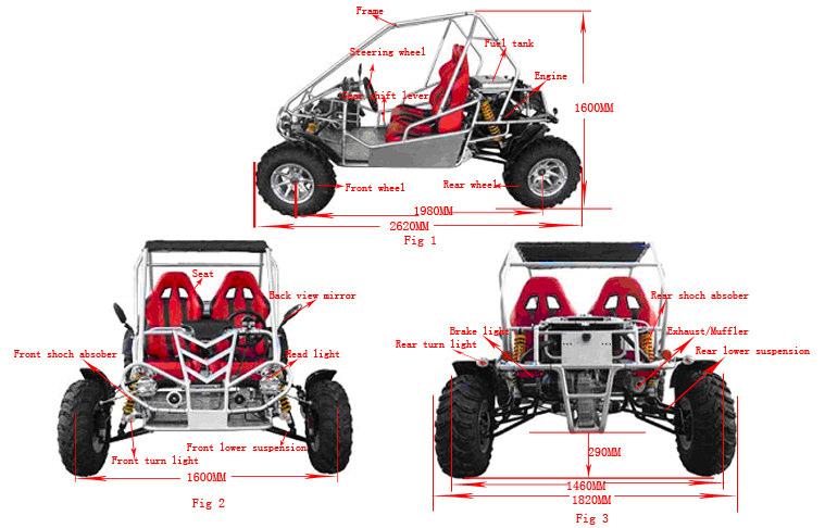
3 1. The performance, Technical parameter and Structure of Go Kart 1.1Performance and Specifications Model GK250-2D/2E Displacement 244cc length 2620mm (106.3 inches) Bore stroke 72 60mm Width 1820mm (70.9 inches) Compression ratio 10:1 Height 1600mm (66.9 inches) Rated power 12.5kw/7500±500r/min Wheelbase 1980mm (78.7 inches) Max torque 17.6N.m/5500r/min Front wheel track 1600mm (61.8 inches) ignition CDI Rear wheel track 1460mm (56.7 inches) lubrication Forced lubrication & splash lubrication Ground clearance 290mm (8.3 inches) Start Electronic Max speed 50km/h Gear shift hand Braking length <7m (30km/h) Spark plug C7HSA Climbing capacity 45 Gross weight 535kg Net weight 360kg Fuel type RQ93 (unleaded) Loading capacity 2person or 175kg Engine oil type SAE15W40(summer) SAE10W/30(winter) Oil mass 1.0 L suspension Front wheel Rocker arm,independent suspension Gear box oil 0.18 L Rear wheel Oleo-pneumatic damping shock absorber Fuel tankage 11 L Brake Front wheel Hydraulic disc brake,right foot control Cooling liquid 1.19L Rear wheel Engine type Single cylinder,4 stroke, liquid cooling Tire Front wheel Battery 12V12Ah Rear wheel Head light 12V/55W Tire pressure Front wheel 200kpa Fuse 15Ah Rear wheel 200kpa Rear light and brake light 12V 5W/10W 2 Component location and structure 3
4 4


5 2. The use of Go Kart 2.1 Safety Note Read this owner s manual carefully and make sure you understand it completely before driving this kart. People under age of sixteen are not allowed to drive this kart. This kart is designed and manufactured for off-road use only. Operation on public streets, roads or high ways is illegal. Please make sure to wear an approved motorcycle helmet and have the seat belt well fastened before driving the kart. Do not drive this kart at night. It s dangerous to drive on an unknown road. Keep a safe distance between your kart and other vehicles. Never risk drunken driving or drive the kart after taking medicine, which will endanger your driving and result in injury even death. Check fuel level before the kart is used. Never refuel the tank while the engine is hot or running. Spilled gasoline should be wiped off prior to starting the engine. Don t drive your kart indoors. Exhaust contains a kind of tasteless, odorless and poisonous gas called carbon monoxide. 2.2 Instrument and control (1) The ignition switch and light switch are located on the right side of steering wheel. Ignition switch Light switch (2) Light Fig 4 After the engine has started, turn on the light switch, both head lights and taillight will be on. When the brake pedal is stepped, the brake light will be on (3) Fuel tank Fuel tank is located close to the rear carrier of the kart. Turn the lid counterclockwise to open and then refuel. The tank capacity is 11 L. (4) Fuel valve Fuel valve is located under the fuel tank, and it has two positions, namely vertical (On) and level (Off). Fuel valve lever (ON) Fuel valve lever (OFF) Fig 5 Fig 6 5
 The parking brake grip is located on the left side of seat.")
 Brake")


6 When the lever is vertical, fuel valve is open. When the lever is horizontal, fuel valve is closed. (5) The parking brake grip is located on the left side of seat. When you stop the cart, step on the brake pedal and pull up the parking-brake grip. If you want to release the kart, just put down the parking-brake grip Parking broke grip (6) Brake pedal Fig 7 Brake pedal is underneath the left side of steering wheel. It controls the front and rear brake discs, operated by left foot. For braking, step down the brake pedal; when you release your foot from the brake pedal, it will automatically return to its normal position. Brake pedal Accelerator pedal (7) Accelerator pedal Fig 8 Accelerator pedal is below the right side of the steering wheel and is controlled by the right foot. To accelerate, step down the pedal ;when you release your foot from the accelerator pedal, it will automatically return to its normal position. (8) Forward and reverse control stick Gear shift leaver Fig 9 6

 The seat back lock lever is underneath the seat, pull up the lever to adjust the seat, when satisfied, release the lever to lock the")


7 Forward and reverse of the vehicle is controlled by the control stick, push the stick into the slot D to make the kart move forward; keep the stick in slot N to park; pull back the stick in slot R to reverse the vehicle. Warning: Make sure the vehicle is completely stopped before changing shift, or it will damage the parts in gearbox. (9) The seat back lock lever is underneath the seat, pull up the lever to adjust the seat, when satisfied, release the lever to lock the position.; seat location adjuster is in the inner side of the seat, pull up to adjust, when satisfied, release the lever to lock Seat back lock switch Fig 10 (10)The gearbox is a small advanced structure, its main function is to control the vehicle forward and backward. Gearbox Fig 11 The reverse ratio is 2.19; please use SAE10-30 engine oil. Drain all the oil in the gearbox before replace the oil.periodically change oil according to the maintenance table in periodical maintenance section. (11) Steering side rod Front wheel alignment can be accomplished by actual use of steering side rod. (The angle of inner obliquity is 1 o, normally no need to adjust) 7
 Smoothly (2) No obstacle (3) No clearance Brake (1) Travel length of pedal is proper (2) No slippery.")


8 Steering side rod Fig Before riding Please check all the following items before driving. Items Purpose Steering (1) Smoothly (2) No obstacle (3) No clearance Brake (1) Travel length of pedal is proper (2) No slippery. Tire (1) Proper pressure (2) No crack or cut. Fuel Keep enough fuel for intended driving distance Light Check all the lamps headlights, tail lamps, stop lamps. Battery Check the electrolyte lever, fill some if necessary 2.4 Basic operation guide Driving this Go Kart is the same as driving a car. 2.5.Grinding in Proper grinding-in of new kart is very important to prolong the life span of the vehicle and achieve its best performance. During the initial 10 hours of your driving, limit the driving speed to 25km/h to avoid early damage of parts due to high driving speed. 2.6.Circuit diagram 8
9 3.Go Kart Maintenance 3.1 Engine maintenance (1) #93 or above unleaded gasoline is recommended. Note: using unleaded gasoline can extend the life of spark plug (2) A. How to choose engine oil User should choose proper type of engine oil according to the local temperature. Please refer to Fig16. a 20W - 40 b 10W - 40 c 10W - 30 d 5W 30 e 5W 20 F C B. Oil Level: The level of engine oil should be between upper scale and lower scale. Upper scale Lower scale Fig 13 C. Oil Filling: Oil should be filled through filling port. After oil filling, let the engine run in idle for 3-5minutes and then check the oil level; add enough if it s inadequate D. Changing Oil: Unscrew the oil drain bolt to let out old oil ; screw down the bolt when all the old oil is let out before new oil is filled in. 9


10 Oil drain bolt Filling port Fig 14 E. Gear oil AP/GL 4SAE75/85,85,80/90 or 90 are recommended for gearbox the amount required is 2 L; and the oil level should be between upper scale and lower scale. Fig 15 3 Cooling liquid A. Cooling system of the engine must be filled with adequate cooling liquid. Cooling liquid is a mixture of water and coolant. Water and coolant should be mixed by a specific ratio (the ratio 60% water and 40% coolant in summer, water and coolant ratio 50% in winter). The water must be distilled water or boiled water. Do not use water direct from well, river or other unclean water. The filling port of the radiator Auxiliary tank Fig 16 10
11 B. After 5-minute running of the engine, stop it and wait for 15 minutes before you inspect the cooling water level. If it is still not enough, add more cooling water to the limit line PERIODICAL MAINTENANCE The maintenance intervals in the following table are based on average riding conditions. Unusual condition requires more frequent service. Time of service Initial service Monthly Quarterly Yearly Items (First wee Tire pressure/wear I I Brake performance I I Tightness of fasteners I I Air cleaner C I Carburetor I A C Spark plug C, A Brake fluid I Engine oil I R Gear box oil I R Oil filter screen C Chassis C, I L Fuel switch/fuel tank I C Battery I Valve clearance of engine A Control cables I Cooling liquid I R Remarks: A: To adjust; C: To clean; I: To inspect, clean or replace if necessary; L: To lubricate; R: To replace. 11
 Fuel tank check Check for enough fuel in the fuel tank. The fuel tank capacity is 11 L. RQ93 or above unleaded gasoline is recommended.")

12 The following are some instructions during the periodical check: 1). Engine oil check Oil level stick Fig 17 Check the oil gauge. Make sure there is enough lubricating oil 2.) Fuel tank check Check for enough fuel in the fuel tank. The fuel tank capacity is 11 L. RQ93 or above unleaded gasoline is recommended. Do not fill too much fuel, or the fuel may overflow and cause a fire. 3.) Tire pressure check Check if the tire pressure is normal. The recommended tire pressure is 98kpa; Check if there are any metal fragments or nails stuck in the tire; if so, remove them immediately. Check if there is any crack or severe tear on the tire, replace the tire if necessary. 4.) Battery check The normal voltage should be above 12.8V; Keep the terminals clean and the connections tight.; If the voltage is below the normal condition, remove the battery to recharge 5.) Chassis check After cleaning the chassis, inspect the body, front and rear suspensions, rocker arm, rear axle and fasteners and check if there is any weld failure, crack or loose connections. Apply some weight to the front bumper and the rear carrier to check the performance of front and rear shock absorber.. 6.)Idling speed adjustment Idle adjusting screw Fig 18 12

13 Start the engine and warm it up for about 5 minutes. Tighten or loosen the idle adjusting screw to make the engine in idle running condition Turn the idle adjusting screw counter-clockwise, the idle speed decrease, whereas clockwise the idle speed increases. The idle speed has already been adjusted to the optimum condition when the kart left the factory. Normally, there is no need to readjust it 7) Brake system check The brake pedal must have proper length of travel. Length of travel is the distance from brake pedal s idle position to it s working position, and it is about 15-25mm. Brake master cylinder Fig 19 Periodically inspect the thickness of the brake disc. It should be replaced in case of any wear of over 1mm. Periodically inspect the level of the brake fluid in the oil cup. When the brake fluid is below the required level, fill new DOT3 or DOT4 brake fluid. Always keep the brake discs and the brake pads clean. 7) Maintenance guide Repair should be done by professional service center, unless the owner has a complete set of repairing tools and maintenance manuals. Stop the engine before repairing the kart. WARNING: If your kart has experienced a collision or overturn, please carefully inspect each part of the kart, such as the frame, suspension and steering device; Driving damaged kart is forbidden as it will endanger yourself. 13
14 4. Trouble Shooting (1) Engine does not start, or suddenly stops during driving, first inspect electrical circuit status and then check for enough fuel in the fuel tank, and then perform following inspection. Troubles Causes Solving methods Engine suddenly stops. (1) Spark short circuit. (2) Carbon accumulation on spark plug. (3) Ignition coil is damaged. (4) Piston seized in the cylinder. (1) Clean or replace (2) Remove accumulated carbon. (3) Replace. (4) Repair or Engine runs more and more slowly, until finally stops running. (1) Fuel dust clogs. (2) Cylinder head blows or gasket is damaged. (1) Clean (2) Tighten or replace (.2) Engine difficult to start Troubles Causes Solving methods Fuel fail to flow into the carburetor. (1) Fuel screen clogged (2) Fuel pipeline clogged. (3) Fuel in the fuel tank exhausted. (4) Fuel valve clogged. (1) Clean and wash (2) Clean and purge. (3) Refuel. (4) Clean and purge Inspection finds the spark is weak. (1) Spark plug damaged. (2) The clearance adjustment of the spark plug is improper. (3) CDI components have defects. (4) The ignition coil is damaged. (1) Replace. (2) Adjust. (3) Replace (4) Replace Spark plug fails to create spark. (1) Spark plug is damaged. (2) Spark plug is dirty or wet or shorted out. (3) The clearance adjustment of the spark plug is improper. (4) CDI components have defects. (5) The ignition switch is damaged. (6) The ignition switch has bad contact. (7) Electrical wire is damaged. The cylinder compression pressure is too low. (1) Too much wear on the cylinder or piston ring. (2) Piston ring gets stuck (3) Cylinder head gasket is damaged. 14 (1) Replace. (2) Clean (3) Adjust. (4) Replace (5) Replace (6) Replace (7) Repair or replace. (1) Repair or replace. (2) Repair (3) Replace
15 (4) Spark plug is loose. (5) Cylinder head has air leakage and is tightened (4) Properly tighten (5) Properly tighten unevenly. (3)Abnormal sound from Engine Troubles Causes Solving methods It is noisier as the rpm increases. (1) Too much clearance between piston and cylinder. (2) Piston ring is too loose. (3) Too much wear at the crank bearing (1) Repair the cylinder or replace it. (2) Replace (3) Replace (4) Braking is bad Trouble Causes Solving methods Braking is not effective (1) Excessive wear at the brake pads. (2) Brake pads are dirty. (3) Brake disc wears or stained with oil. (4) Too much idle travel (5) There is air in the hydraulic braking system. (1) Replace (2) Clean. (3) Clean or replace (4) Adjust (5) Eliminate air (5). Fuel consuming is too much Troubles Causes Solving methods Fuel consuming too much (1) Carburetor adjustment is not proper (2) Fuel pipeline leakage (3) Carburetor float dose not work (4) Brakes drag (5) Tire pressure is not enough (6) Engine works improperly (7) Too much dirt in the air cleaner and cause it clogging and too thick mixed air (1) Adjust the carburetor (2) Find the repair the leakage (3) Repair or replace (4) Adjust until brakes move smoothly. (5) Inflate the tire to its prescribed pressure (6) Inspect the engine (7) Maintain the air cleaner, and clear the dirt and dust, or replace the filter Product identification number: 5. VIN Please take down the frame number and engine number for reference. The frame number is stamped on back of the kart. 15
BLAZER250 OWNER S MANUAL BOOK FORWARD. Sincerely appreciate your choice of our vehicle, we will provide you the best services.
 BLAZER250 OWNER S MANUAL BOOK FORWARD Sincerely appreciate your choice of our vehicle, we will provide you the best services. This Owner s manual contains important safety and maintenance information.
ATV-320 R OWNER S MANUAL
 ATV-320 R OWNER S MANUAL FOREWORD May we, the manufacturer, take this opportunity to thank you for choosing our ATV to serve you. This Owner s Manual is prepared for you to properly operate in safety.
May we, the manufacturer, take this opportunity to thank you for choosing our ATV to serve you.
 FOREWORD May we, the manufacturer, take this opportunity to thank you for choosing our ATV to serve you. This Owner s Manual is prepared for you the details as to operate and maintenance necessarily to
ATV-50/90/100 I/II/V OWNER S MANUAL
 1 ATV-50/90/100 I/II/V OWNER S MANUAL FOREWORD May we, the manufacturer, take this opportunity to thank you for choosing our ATV to serve you. This Owner s Manual is prepared for you the details as to
ATV-320 S/U ATV-320SD S/U OWNER S MANUAL V
 ATV-320 S/U ATV-320SD S/U OWNER S MANUAL V1.0 2014.03.01 0 FOREWORD May we, the manufacturer, take this opportunity to thank you for choosing our ATV to serve you. This Owner s Manual is prepared for you
BT49QT-9O3 User s Manual
 BT49QT-9O3 User s Manual Preface Thank you very much for purchasing BAOTIAN brand motorcycle of model BT49QT-9O3, which developed by BAOTIAN MOTORCYCLE INDUSTRIAL CO., LTD. And welcome to join the driver
NOTES FOR SAFETY OPERATOR-ONLY.
 NOTES FOR SAFETY Both the parents and their child must fully understand everything in this manual before riding. This vehicle is for OPERATOR-ONLY. This vehicle is only designed for operation on level,
3. INSPECTION/ADJUSTMENT
 3 3 INSPECTION/ADJUSTMENT SERVICE INFORMATION -------------------------------------------- 3-1 MAINTENANCE SCHEDULE ---------------------------------------- 3-2 FUEL LINE/FUEL FILTER -------------------------------------------
INSPECTION/ADJUSTMENT
 3 3 INSPECTION/ADJUSTMENT SERVICE INFORMATION----------------------------------------------------------------------- 3-1 MAINTENANCE SCHEDULE-------------------------------------------------------------------
3. INSPECTION/ADJUSTMENT
 3 SERVICE INFORMATION...3-0 FINAL REDUCTION GEAR OIL...3-7 MAINTENANCE SCHEDULE...3-2 DRIVE BELT...3-7 FUEL FILTER...3-3 BRAKE SHOE...3-8 THROTTLE OPERATION...3-3 BRAKE ADJUSTING NUT...3-8 AIR CLEANER...3-4
3. INSPECTION/ADJUSTMENT
 SERVICE INFORMATION...3-0 FINAL REDUCTION GEAR OIL...3-7 MAINTENANCE SCHEDULE...3-2 DRIVE BELT...3-7 FUEL FILTER...3-3 BRAKE SHOE...3-8 THROTTLE OPERATION...3-3 BRAKE ADJUSTING NUT...3-8 AIR CLEANER...3-4
Racing NAVODILO ZA UPORABO USER'S MANUAL
 Racing NAVODILO ZA UPORABO USER'S MANUAL TOMOS USER'S MANUAL YOUNGST'R YOUNGST'R FULL RACING 45 1 CONTENTS Warnings 3 Riding Safety Tips 3 Technical Specification 4-5 Technical Description 6-9 Vehicle
Engine Does Not Start or Is Hard to Start Cause of Trouble. 1. Open the drain screw, and check Fuel not supplied (1) Fuel tank empty
 Fuel tank empty") 20. Engine Does Not Start or Is Hard to Start 20-1 Engine Output Insufficient 20-2 Poor Performance at Low Speed and Idling 20-3 Poor Performance at High Speed 20-3 Unsatisfactory Operation 20-4 Fuel Gauge
20. Engine Does Not Start or Is Hard to Start 20-1 Engine Output Insufficient 20-2 Poor Performance at Low Speed and Idling 20-3 Poor Performance at High Speed 20-3 Unsatisfactory Operation 20-4 Fuel Gauge
USER MANUAL. GASOLINE SCOOTER (4 Stroke engine) OFF ROAD USE ONLY. Read these instruction carefully before using
 OFF ROAD USE ONLY. Read these instruction carefully before using") USER MANUAL GASOLINE SCOOTER (4 Stroke engine) OFF ROAD USE ONLY Read these instruction carefully before using Ⅰ.Safe for use(caution) 1. Don t allow anyone who dose not understand this instruction manual
USER MANUAL GASOLINE SCOOTER (4 Stroke engine) OFF ROAD USE ONLY Read these instruction carefully before using Ⅰ.Safe for use(caution) 1. Don t allow anyone who dose not understand this instruction manual
RASER R1/ RASER FX OWNER'S MANUAL
 RASER R1/ RASER FX OWNER'S MANUAL IMPORTANT NOTES FOR SAFE OPERATION FAILURE TO FOLLOW THE INSTRUCTIONS CONTAINED HEREIN MAY RESULT IN DAMAGE TO YOUR SCOOTER, DECREASE ENGINE LIFE, CAUSE INJURY TO YOURSELF
CHASSIS CONTENTS EXTERIOR PARTS 7-1 FRONT WHEEL 7-2 FRONT BRAKE 7-6 HANDLEBARS 7-13 FRONT FORK 7-15 STEERING 7-23 REAR WHEEL 7-26 REAR BRAKE 7-30
 CHASSIS CONTENTS EXTERIOR PARTS 7- FRONT WHEEL 7-2 FRONT BRAKE 7-6 HANDLEBARS 7-3 FRONT FORK 7-5 STEERING 7-23 REAR WHEEL 7-26 REAR BRAKE 7-30 REAR SHOCK ABSORBER 7-32 SWING ARM 7-33 7 7- CHASSIS EXTERIOR
3. INSPECTION/ADJUSTMENT
 3 3 INSPECTION/ADJUSTMENT SERVICE INFORMATION-------------------------------------------------- 3-1 MAINTENANCE SCHEDULE---------------------------------------------- 3-3 FUEL LINE---------------------------------------------------------------------
1.CONTENTS 1. Contents Control location Before riding Safe riding Driving Use genuine spare parts Use
 1.CONTENTS 1. Contents... 1 2. Control location... 3 3. Before riding... 4 4. Safe riding... 4 5. Driving... 5 6. Use genuine spare parts... 5 7. Use of each component... 6 Gauges... 6 Operation of ignition
KING CANADA 950W PORTABLE GENERATOR MODEL: KCG-951G INSTRUCTION MANUAL COPYRIGHT 2011 ALL RIGHTS RESERVED BY KING CANADA TOOLS INC.
 KING CANADA 950W PORTABLE GENERATOR MODEL: KCG-951G INSTRUCTION MANUAL COPYRIGHT 2011 ALL RIGHTS RESERVED BY KING CANADA TOOLS INC. WARRANTY & SERVICE INFORMATION 1-YEAR LIMITED WARRANTY FOR THIS 950W
PERIODIC MAINTENANCE
 PERIODIC MAINTENANCE CONTENTS PERIODIC MAINTENANCE SCHEDULE 2 1 MAINTENANCE PROCEDURES 2 3 2 BATTERY 2 3 CYLINDER HEAD NUTS AND EXHAUST PIPE NUTS 2 4 CYLINDER HEAD AND CYLINDER 2 4 SPARK PLUG 2 4 FUEL
SERIES OFF-ROAD KART USER S MANUAL. Thank you very much for your choice of this Off-road Kart.
 SERIES OFF-ROAD KART USER S MANUAL Dear Sir or Madam, Thank you very much for your choice of this Off-road Kart. This Off-road Kart is manufactured according to the full survey of market demand. We hope
AIR-COOLED DIESEL GENERATOR OWNERʼS MANUAL. This manual contains important safety information. TDG2500E TDGW7000E TDG7000SE TDG4500E
 AIR-COOLED DIESEL GENERATOR OWNERʼS MANUAL This manual contains important safety information. TDG2500E TDGW7000E TDG7000SE TDG4500E TDG8000-3 TDG7000SE-3 TDG7000E TDG8000E TDGW7000SE TDG7000E3 TDGW8000E
Gasoline Inverter Generator
 user manual Gasoline Inverter Generator table of contents Preface Introduction... Safety Information Exhaust fumes are poisonous... Fuel is highly flammable and poisonous... Engine and muffler may be hot...
GASOLINE GENERATOR SET USER S MANUAL
 GASOLINE GENERATOR SET USER S MANUAL Foreword Thank you for purchasing our gasoline generator and hope that you will enjoy operating your unit, one of the finest models in the market. This Manual provides
Follow the Age Recommendation Adult Supervision should be present for all people under the age of 18.
 Your Kart will provide you with many years of service and pleasure. Providing you take responsibility for your own safety and understand the challenges you can meet while driving. There is much that you
CHASSIS CONTENTS EXTERIOR PARTS 6-1 FRAME COVER 6-2 REAR FRAME COVER 6-4 FRONT WHEEL 6-6 FRONT BRAKE 6-10 HANDLEBARS 6-17 FRONT FORK 6-19
 CHASSIS CONTENTS EXTERIOR PARTS 6- FRAME COVER 6- REAR FRAME COVER 6-4 FRONT WHEEL 6-6 FRONT BRAKE 6-0 HANDLEBARS 6-7 FRONT FORK 6-9 STEERING 6-6 REAR WHEEL 6-3 REAR BRAKE 6-39 6 REAR SHOCK ABSORBER 6-43
DAZON Limited Warranty
 1 DAZON Limited Warranty The warranty policy applies to those cases where the new seller vehicle unloaded from its shipping container, set up and delivered by authorize dealer and under normal use and
Light condition and operation Windshield glass condition Wiper blade condition Paint condition and corrosion Fluid leaks Door and hood lock condition
 GENERAL CHECKS Engine Compartment The following should be checked regularly: Engine oil level and condition Transmission fluid level and condition Brake fluid level Clutch fluid level Engine coolant level
Owner s manual. 150CC Go-Kart FOR OFF-ROAD USE ONLY READ THIS MANUAL CAREFULLY IT CONTAINS IMPORTANT SAFETY INFORMATION.
 Owner s manual READ THIS MANUAL CAREFULLY IT CONTAINS IMPORTANT SAFETY INFORMATION. MINIMUM RECOMMENDED OPERATOR AGE 14 150CC Go-Kart FOR OFF-ROAD USE ONLY OWNER S MANUAL FOREWORD 1 A FEW WORDS ABOUT SAFETY
Water pump Owner's Manual
 Water pump Owner's Manual Safety Precautions I. General Safeguards Please read this operation manual to have a thorough understanding of the content there before use the product. Failure to do so may lead
EW-54. Owners Manual.
 EW-54 Owners Manual www.electricwheelstore.com Dear consumers, Foreword Welcome to the big family of Electric Wheels, and thank you for your choice of Electric Wheels electric tricycle! The electric tricycle
Instruction Model 18537
 Instruction 738-556 Model 18537 LIMITED WARRANTY H. D. Hudson Manufacturing Company warrants to the original purchaser only that this product will continue to function as intended if used in accordance
WEBER CARBURETOR TROUBLESHOOTING GUIDE
 This guide is to help pinpoint problems by diagnosing engine symptoms associated with specific vehicle operating conditions. The chart will guide you step by step to help correct these problems. For successful
SERVICE MANUAL HYOSUNG MOTORS & MACHINERY INC HR8310 SERVICE MANUAL
 HYOSUNG MOTORS & MACHINERY INC. SERVICE MANUAL SERVICE MANUAL 99000HR8310 FOREWORD GROUP INDEX This manual contains an introductory description on HYOSUNG & and procedures for its inspection/service and
CHASSIS CONTENTS FRONT WHEEL 6-1 FRONT BRAKE 6-6 FRONT FORK 6-14 STEERING STEM 6-20 REAR WHEEL AND REAR BRAKE 6-25 SUSPENSION 6-31 REAR SWING ARM 6-36
 CHASSIS CONTENTS FRONT WHEEL 6-1 FRONT BRAKE 6-6 FRONT FORK 6-14 STEERING STEM 6-20 REAR WHEEL AND REAR BRAKE 6-25 SUSPENSION 6-31 REAR SWING ARM 6-36 6 6-1 CHASSIS FRONT WHEEL REMOVAL Support the machine
CHASSIS CONTENTS EXTERIOR PARTS 6-1 FRONT WHEEL 6-2 FRONT BRAKE 6-6 HANDLEBARS 6-12 REAR WHEEL 6-30 REAR BRAKE 6-34 REAR SHOCK ABSORBER 6-36
 CHASSIS CONTENTS EXTERIOR PARTS 6-1 FRONT WHEEL 6-2 FRONT BRAKE 6-6 HANDLEBARS 6-12 FRONT FORK ( ) 6-14 FRONT FORK ( ) 6-20 STEERING 6-27 REAR WHEEL 6-30 REAR BRAKE 6-34 REAR SHOCK ABSORBER 6-36 6 SWING
2.CONTROL LOCATION MODEL: ORBIT II 125(AE12W1-6)
") 1.CONTENTS 1. Contents... 1 2. Control location... 3 3. Before riding... 4 4. Safe riding... 4 5. Driving... 5 6. Use genuine spare parts... 5 7. Use of each component... 6 Gauges... 6 Operation of ignition
1.CONTENTS 1. Contents... 1 2. Control location... 3 3. Before riding... 4 4. Safe riding... 4 5. Driving... 5 6. Use genuine spare parts... 5 7. Use of each component... 6 Gauges... 6 Operation of ignition
MIKUNI VM26 Carburetor Kit Instruction Manual
 MIKUNI VM26 Carburetor Kit Instruction Manual (For exclusive use in the Super Head 4VALVE+R-equipped motorcycle) Item No. (Carburetor set) AKEGAWA-made products. Please strictly follow the following instructions
BRAKE SYSTEM Return To Main Table of Contents
 BRAKE SYSTEM Return To Main Table of Contents GENERAL... 2 BRAKE PEDAL... 10 MASTER CYLINDER... 13 BRAKE BOOSTER... 16 BRAKE LINE... 18 PROPORTIONING VALVE... 19 FRONT DISC BRAKE... 20 REAR DRUM BRAKE...
LDG6000SA DIESEL GENERATOR OWNERS MANUAL
 LDG6000SA DIESEL GENERATOR OWNERS MANUAL BEFORE OPERATING THIS EQUIPMENT PLEASE READ THESE INSTRUCTIONS CAREFULLY Preface Thank-you for purchasing this generator. This operation manual contains information
SECTION 5 MAINTENANCE
 SECTION 5 Maintenance requirements................................ 166 General maintenance..................................... 167 Does your vehicle need repairing?......................... 170 Scheduled
Parking brake Mechanical brake acting on rear wheels
 11 Brake System 11.1 General SPECIFICATIONS EJTC0010 Master cylinder Type Tandem type I.D. mm(in.) 20.64 mm (0.813 in.) Fluid level warning sensor Provided Brake booster Type Vacuum Boosting ratio 4.0
IMPORTANT: Read this manual fully before assembly and use and observe all safety rules and operating instructions
 PETROL ENGINE Model: MLR52 IMPORTANT: Read this manual fully before assembly and use and observe all safety rules and operating instructions Contents Technical Specification 2 Safety 3 Starting 5 Running
John Deere. MODEL: 1010 Gasoline Wheel Tractor JD-O-OMT15504
 John Deere MODEL: Gasoline Wheel Tractor THIS IS A MANUAL PRODUCED BY JENSALES INC. WITHOUT THE AUTHORIZATION OF JOHN DEERE OR IT'S SUCCESSORS. JOHN DEERE AND IT'S SUCCESSORS ARE NOT RESPONSIBLE FOR THE
SAFE DRIVE IMPORTANT. SMR Motorcycle congratulates you on choosing one of its products. ATTENTION
 1 SAFE DRIVE This vehicle must only be run on racetracks and away from normal roads. Parents are responsible for the safety of children, therefore they must pay the utmost attention to them; Always wear
YK1900i DIGITAL INVERTER GASOLINE GENERATOR OWNER S MANUAL PLEASE READ THIS MANUAL CAREFULLY. IT CONTAINS IMPORTANT SAFETY INFORMATION.
 YK1900i DIGITAL INVERTER GASOLINE GENERATOR OWNER S MANUAL PLEASE READ THIS MANUAL CAREFULLY. IT CONTAINS IMPORTANT SAFETY INFORMATION. PREFACE Thank you for purchasing YANGKE generator. This manual covers
OWNERS MANUAL. Two Stroke Dirt Bike. Distributed by SSR Motorsports. Address: Alondra Blvd, Norwalk CA
 OWNERS MANUAL Two Stroke Dirt Bike Distributed by SSR Motorsports Address: 12825 Alondra Blvd, Norwalk CA 90650 www.ssrmotorsports.com Please note that this is a general manual. The model of the vehicle
FORZA BOSS OUTBOARD MOTOR
 FORZA BOSS OUTBOARD MOTOR Table of Contents 1. Safety Information.....1 2. Product Features and Operation... 2 3. Technical Features and Specifications......6 4. Overall Dimensions...8 5. Installation..........8
20. TROUBLESHOOTING ENGINE DOES NOT START OR IS HARD TO START XL200
 20. ENGINE DOES NOT START OR IS HARD TO START 20-1 ENGINE LACKS POWER 20-2 POOR PERFORMANCE AT LOW AND IDLE SPEED 20-3 POOR PERFORMANCE AT HIGH SPEED 20-4 POOR HANDLING 20-4 ENGINE DOES NOT START OR IS
I: INSPECT AND CLEAN, ADJUST, LUBRICATE OR REPLACE IF NECESSARY C: CLEAN A: ADJUST R: REPLACE L: LUBRICATE I: INSPECTION D: DIAGNOSE
 2. Periodic Maintenance > Periodic Maintenance Chart XCITING 400i Maintenance Schedule Perform the pre-ride inspection (Owner's Manual) at each scheduled maintenance period. This interval should be judged
SERVICE DATA ITEM STD/SPEC. LIMIT. ( in) 1st & 2nd R Approx. 8.2 mm (0.32 in)
 1st & 2nd R Approx. 8.2 mm (0.32 in)") 2 STROKE CYLINDER + PISTON + PISTON RING CONROD + CRANKSHAFT CLUTCH SERVICE DATA Piston to cylinder clearance 0.045 0.055 mm (0.0018 0.0022 in) 0.120 mm (0.0047 in) Cylinder bore Piston diam. Cylinder
2 STROKE CYLINDER + PISTON + PISTON RING CONROD + CRANKSHAFT CLUTCH SERVICE DATA Piston to cylinder clearance 0.045 0.055 mm (0.0018 0.0022 in) 0.120 mm (0.0047 in) Cylinder bore Piston diam. Cylinder
5. FUEL SYSTEM FUEL SYSTEM 5-0
 5 FUEL SYSTEM 5-0 SERVICE INFORMATION GENERAL INSTRUCTIONS SERVICE INFORMATION...5-1 CARBURETOR INSTALLATION...5-9 TROUBLESHOOTING...5-1 PILOT SCREW ADJUSTMENT...5-10 CARBURETOR REMOVAL...5-2 AUTO BYSTARTER...5-3
Operator s Manual ACCESS MOTOR
 Operator s Manual ACCESS MOTOR TE-250/300U 250/300 2x4 Dear Customers, Thank you for purchasing TE-250/300U. You will find it easier to start your engine with actuation of the manual choke for 20-30 seconds
BRAKE E
 8-1 GENERAL...8-2 SPECIFICATIONS...8-6 COMPONENTS...8-7 FRONT BRAKE...8-12 DISASSEMBLY INSPECTION REASSEMBLY (Pn1, Cu2 3 TON SERIES)...8-12 DISASSEMBLY INSPECTION REASSEMBLY (Pn2 3 TON SERIES)...8-17 BRAKE
February 26, ch.12.notebook. Ch. 12. Preventative Maintenance and Troubleshooting. Feb 23 5:03 PM
 Ch. 12 Preventative Maintenance and Troubleshooting Feb 23 5:03 PM 1 Why PM? preventive maintenance certain maintenance tasks must be performed regularly to keep an engine working properly helps premature
Motorcycle - Specifications
 Motorcycle - Specifications Model Name FZ400R Model Code 46X0 Model Year 1985 Destination JAPAN Section/Item Chassis Maintenance Specification (Chassis) Chassis Frame type Double cradle Caster angle 26.00
Instruction Manual. Vibratory Plate Compactor
 Instruction Manual Vibratory Plate Compactor Model VPC45R Model VPC65R Model VPC85R Model VPC95R Table of Contents 1. INTRODUCTION...1 2. SAFETY...1-2 3. SPECIFICATIONS.....2 4. APPLICATION.. 2 5. CHECK
2. CONTROL LOCATION MODEL: AJ05W5-6 AJ05W6-6 AJ05W7-D AJ12W2-6. Helmet hook. Front light/ Position light. Seat lock. Air Cleaner. Kick starter pedal
 1. CONTENTS 1. Contents... 1 2. Control location... 3 3. Before riding... 4 4. Safe riding... 4 5. Driving... 5 6. Use genuine spare parts... 5 7. Use of each component... 6 Gauges... 6 Operation of ignition
2. CONTROL LOCATION. Oil level HU05 / HU10 SERIES. Fuel tank. Front turn. light. Fuel tank cap. Fuses & C.D.I. & Battery. Helmet hook.
 1. CONTENTS 1. Contents... 1 2. Control Location... 3 3. Before Riding... 4 4. Safe Riding... 4 5. Riding... 5 6. Use Genuine Spare Parts... 5 7. Use of Each Component... 6 Gauges... 6 Operation of Ignition
OPEN-FRAME GASOLINE GENERATOR
 R WUXI KIPOR POWER CO., LTD. OPEN-FRAME GASOLINE GENERATOR SINGLE-PHASE KGE2500X/E KGE4000X KGE6500X/E THREE-PHASE KGE6500X3/E3 CONTENTS 1. Safety information 2. Identification of components 3. Pre-operation
SECTION 8 2 DO IT YOURSELF MAINTENANCE. Chassis
 DO IT YOURSELF MAINTENANCE Chassis SECTION 8 2 Checking the coolant level of the traction motor................ 184 Checking the radiator....................................... 185 Checking brake fluid........................................
Typical Install Instructions
 Typical Install Instructions Read & understand all steps of these instructions before beginning this installation. WEBER Conversion Kit, VW T-1/2, up to 1835cc 32 / 36 DFEV Weber Carburetor These instructions
BR-250 / BR-250SS / M2-250 SERVICE MANUAL
 BR-250 / BR-250SS / M2-250 SERVICE MANUAL Manufactured by PGO of Motive Power Industry Co., Ltd 1. INSPECTION/ADJUSTMENT 1 1 INSPECTION/ADJUSTMENT SERVICE INFORMATION -------------------------------------------------
PREFACE. Thank you for your purchase of the Böhler-AG Petrol Generator.
 1 PREFACE Thank you for your purchase of the Böhler-AG Petrol Generator. The Böhler-AG Petrol Generator is a Powerful, low fuel consumption, low pollution, low noise, simple to operate and easy to move.
2. CONTROL LOCATION MODEL: AY05W-T. Helmet hook Storage box. Rear brake level. Air Cleaner. Kick starter pedal. Engine number.
 1. CONTENTS 1. Contents... 1 2. Control location... 3 3. Before riding... 4 4. Safe riding... 4 5. Driving... 5 6. Use genuine spare parts... 5 7. Use of each component... 6 Gauges... 6 Operation of ignition
Do not bend or twist the control cable. Damaged control cable will not operate smoothly and may stick or bind.
 XL200 4. FUEL SYSTEM SERVICE INFORMATION 4-1 TROUBLESHOOTING 4-2 CARBURETOR 4-3 PILOT SCREW ADJUSTMENT 4-14 ACCELERATOR PUMP ADJUSTMENT 4-15 AIR CLEANER HOUSING 4-15 FUEL TANK 4-16 SERVICE INFORMATION
12. CARBURETOR 12-0 CARBURETOR VITALITY 50
 12 12 CARBURETOR SERVICE INFORMATION (2-STROKE)... 12-2 SERVICE INFORMATION (4-STROKE)... 12-3 THROTTLE VALVE (2-STROKE)... 12-5 CARBURETOR (2-STROKE)... 12-7 AIR SCREW ADJUSTMENT (2-STROKE)... 12-13 REED
Property of American Airlines
 MH Utility Vehicle Section 3 SECTION 3: SPECIFICATIONS AND CAPABILITIES A. DIMENSIONS 1. Length, Excluding Coupler... 153 inches (389 cm) 2. Width, Overall... 78 inches (198 cm) 3. Height, Overall... 78
11 OPERATION AND VERIFICATION
 11 OPERATION AND VERIFICATION Section Page 11.1 PREPARATION FOR A FIRST TIME START... 11-3 11.2 STARTING THE ENGINE... 11-9 11.3 RUNNING THE ENGINE... 11-12 11.4 STOPPING THE ENGINE... 11-14 (Rev. 3/04)
2.CONTROL LOCATION MODEL: PCH 50 & PCH125 & PCH150. High& Low beam/turn signal/seat open/horn switch. Rear brake level. Helmet hook.
 1 1.CONTENTS 1. Contents... 1 2. Control location... 3 3. Before riding... 4 4. Safe riding... 4 5. Driving... 5 6. Use genuine spare parts... 5 7. Use of each component... 6 Gauges... 6 Operation of ignition
4. FUEL SYSTEM CK 1 4-0
 4 4 4-0 SERVICE INFORMATION... 4-1 FLOAT LEVEL INSPECTION... 4-5 TROUBLESHOOTING... 4-2 CARBURETOR INSTALLATION... 4-6 THROTTLE VALVE DISASSEMBLY... 4-3 THROTTLE VALVE ASSEMBLY... 4-6 CARBURETOR REMOVAL...
Raider-Classic 150 (Oil-cooled&Internal Gearbox): Service Manual (single/ double-seat) FOREWORD
: Service Manual (single/ double-seat) FOREWORD") FOREWORD This service manual has been specially prepared to provide all the necessary information for the proper maintenance and repair of the RAIDER CLASSIC 150 (EEC-approved for on-road use). The Buggy
FOREWORD This service manual has been specially prepared to provide all the necessary information for the proper maintenance and repair of the RAIDER CLASSIC 150 (EEC-approved for on-road use). The Buggy
GENERATOR MODEL NO: FG3005 OPERATION & MAINTENANCE INSTRUCTIONS PART NO: LS0413
 GENERATOR MODEL NO: FG3005 PART NO: 8857707 OPERATION & MAINTENANCE INSTRUCTIONS LS0413 INTRODUCTION Thank you for purchasing this CLARKE Generator. Before attempting to use this product, please read this
COLT 2310, 2510, AND 2712 COM PACT TRACTORS CHAPTER 9 TROUBLESHOOTING AND ANALYSIS
 COLT 2310, 2510, AND 2712 COM PACT TRACTORS CHAPTER 9 TROUBLESHOOTING AND ANALYSIS 9-A-1 UPON RECEIVING ANENGINE FORRE- PAIR. Learn the history of the unit from the customer. While the customer is present
Owner s Manual ELECTRIC GENERADORS R7100DP / G7100G
 Owner s Manual ELECTRIC GENERADORS R7100DP / G7100G Thank you for choosing a generator set of our company. This manual contains the information on how to do that. Please read it carefully before operating.
Lazer5 Owner s Manual
 Lazer5 Owner s Manual 1 Preface Thank You for purchasing the Lazer5 50cc Moped, it will bring you years of pleasurable riding in a safe to operate package. Riding a moped is one of the most exciting past
This owner's manual is considered a permanent part of the engine and should remain with the engine if resold.
 Thank you for purchasing a water pump. Please reliably keep this Manual for your reference at any time. This owner's manual is considered a permanent part of the engine and should remain with the engine
Engines Original Instructions Model: DG350
 Engines Original Instructions Model: DG350 Henton and Chattell Ltd: London Road, Nottingham NG2 3HW. UK. CONTENTS SECTION 1 INTRODUCTION......3 SECTION 2 SAFETY MESSAGES...3 SECTION 3 SAFETY INFORMATION...3
A SYSTEMATIC SEQUENCE FOR PM INSPECTIONS
 A SYSTEMATIC SEQUENCE FOR PM INSPECTIONS TYPE OF INSPECTION UNDER THE HOOD GASOLINE AND DIESEL 1 Fuel, oil, exhaust leaks - inspect 2 Oil and fuel lines inspect for kinks and wear 3 Automatic transmission
YFZ450S OWNER S MANUAL WARNING. READ THIS MANUAL CAREFULLY! It contains important safety information.
 READ THIS MANUAL CAREFULLY! It contains important safety information. OWNER S MANUAL WARNING LIT-11626-17-11 YFZ450S This ATV should not be ridden by anyone under 16 years of age. 5TG-28199-10 EBU00776
User Manual of Bagibike Electric Bicycles
 User Manual of Bagibike Electric Bicycles Model: Bagibike B16. http://www.bagibike.com Page 1 FOREWORD The following operation manual is a guide to assist you. This manual is not a complete document on
Instructions Suzuki Samurai Brake System Bleeding. Suggested Tools:
 86-95 Suzuki Samurai Brake System Bleeding Instructions CAUTION: Safety glasses should be worn at all times when working with vehicles and related tools and equipment. Suggested Tools: Brake Fluid, DOT
PF-4000, PF-4010, PF-4210 MULTI-PURPOSE ENGINE
 PF-4000, PF-4010, PF-4210 MULTI-PURPOSE ENGINE Date 09-26-01 Supplier To The Outdoor Power Equipment Industry ISM, Inc. 1028 4 th Street SW Auburn, WA 98001 Phone: (253) 333-1200 Fax: (253) 333-1212 WWW.TANAKA-USA.COM
MXU 300/250/150 OFF-ROAD
 OWNER'S MANUAL KWANG YANG MOTOR CO.,LTD. MXU 300/250/150 OFF-ROAD Issued: 01.JUL.2005 IMPORTANT NOTICES READ THIS MANUAL CAREFULLY Your Owner's Manual contains important information on safety, operation,
2004 IMPREZA SERVICE MANUAL QUICK REFERENCE INDEX
 2004 IMPREZA SERVICE MANUAL QUICK REFERENCE INDEX ENGINE SECTION 1 FU(H4SO) EMISSION CONTROL (AUX. EMISSION CONTROL DEVICES) INTAKE (INDUCTION) EC(H4SO) IN(H4SO) This service manual has been prepared to
SERVICE MANUAL ATV-50/100 R HER CHEE INDUSTRIAL CO., LTD. MARCH, High Power Engine
 SERVICE MANUAL ATV-50/00 R MARCH, 005 High Power Engine HER CHEE INDUSTRIAL CO., LTD. Foreword This service manual contains information on servicing ATV-50/00R. This manual is written for use as a guideline
9.7 Replacement of the compressed air distributor
 9.6.6 9.6.7 screw in the bolt and to increase unscrew the bolt. For a complete rotation of the bolt, the variation is of 1mm. After measuring the pointer position and the compensatory adjustment screw
SECTION 6 2 SERVICE PROCEDURES AND SPECIFICATIONS. Engine. Specifications
 SERVICE PROCEDURES AND SPECIFICATIONS Engine SECTION 6 2 Specifications........................................... 170 Fuel.................................................... 172 Facts about engine oil
3. INSPECTION/ADJUSTMENT
 3 INSPECTION/ADJUSTMENT SERVICE INFORMATION------------------------------------------------ 3-1 MAINTENANCE SCHEDULE-------------------------------------------- 3-3 FUEL LINE/THROTTLE OPERATION---------------------------------
SERVICE DATA Date: July 27, 2001 Model: RM250K2
 2 STROKE CYLINDER + PISTON + PISTON RING Piston to cylinder clearance 0.050 0.060 mm 0.120 mm (0.0020 0.0024 in) (0.0047 in) Cylinder bore 66.400 66.415 mm (2.6142 2.6148 in) Nicks or Measure 20 mm (0.79
GENERATOR MODEL NO: FG3000 OPERATION & MAINTENANCE INSTRUCTIONS PART NO: LS0609
 GENERATOR MODEL NO: FG3000 PART NO: 8857700 OPERATION & MAINTENANCE INSTRUCTIONS LS0609 INTRODUCTION Thank you for purchasing this CLARKE Generator. Before attempting to use this product, please read this
EGL MOTOR OWNER S MANUAL-LYDA203E-6 WARNING: READ THIS MANUAL CAREFULLY!
 EGL MOTOR OWNER S MANUAL-LYDA203E-6 WARNING: READ THIS MANUAL CAREFULLY! INTRODUCTION Thank you for your purchase LINGYING ATV LYDA203E-6 series. This manual will provide you with a good basic understanding
OWNER S MANUAL MRT 50-MRT SM 50 MRT 50 PRO-MRT SM 50 PRO
 OWNER S MANUAL MRT 50-MRT SM 50 MRT 50 PRO-MRT SM 50 PRO english RIEJU S.A. is grateful for the confidence you have put in their company and would like to congratulate you on your choice of motorcycle.
Raider Mini 90 (single/double-seat): Service Manual Version:2.0 Feb FOREWORD
: Service Manual Version:2.0 Feb FOREWORD") FOREWORD This service manual has been specially prepared to provide all the necessary information for the proper maintenance and repair of the Raider Mini 90. The Raider Mini 90 fits the needs of a wide
FOREWORD This service manual has been specially prepared to provide all the necessary information for the proper maintenance and repair of the Raider Mini 90. The Raider Mini 90 fits the needs of a wide
CHEM-TEX POWER MAX 25 GOLD EDITION TRUCK MOUNT MANUAL
 CHEM-TEX POWER MAX 25 GOLD EDITION TRUCK MOUNT MANUAL Congratulations On your purchase of a Power Max 25 Gold Edition Truck mount. The Power Max 25 Gold Edition are designed for the professional cleaning
ENGINE LUBRICATION & COOLING SYSTEMS SECTIONLC CONTENTS. ENGINE LUBRICATION SYSTEM...2 Precautions...2
 ENGINE LUBRICATION & COOLING SYSTEMS SECTIONLC CONTENTS ENGINE LUBRICATION SYSTEM...2 Precautions...2 LIQUID GASKET APPLICATION PROCEDURE...2 Preparation...2 SPECIAL SERVICE TOOLS...2 Lubrication Circuit...3
MOTORCYCLE OWNER S MANUAL
 MOTORCYCLE OWNER S MANUAL SNAKE EYES XF250-GS SSR MOTORSPORTS INC. Important Cautions About motorcycle break-in: The first 600 miles of operation is very important in the entire service life of a motorcycle.
WINDSHIELD WIPER BLADES
 OUTSIDE VEHICLE OUTSIDE VEHICLE GENERAL These are maintenance and inspection items which are considered to be the owner s responsibility. They can be done by the owner or they can have them done at a service
AG-HA-2500N GASOLINE GENERATOR
 AG-HA-2500N GASOLINE GENERATOR OWNER S MANUAL BEFORE OPERATING THIS EQUIPMENT PLEASE READ THESE INSTRUCTIONS CAREFULLY (I)WARNING 1. Read the operator s instruction manual. 2. Attention! Exhaust gases
SAVE THESE INSTRUCTIONS
 OPERATION MANUAL WARHORSE IMPORTANT SAFETY INSTRUCTIONS WARNING: Failure to observe these instructions can cause personal injury to machine operator or bystanders. WARNING: Asphyxiation Hazard. An improperly