Operator s Manual ACCESS MOTOR
|
|
|
- Cora Armstrong
- 5 years ago
- Views:
Transcription
1 Operator s Manual ACCESS MOTOR TE-250/300U 250/300 2x4
2 Dear Customers, Thank you for purchasing TE-250/300U. You will find it easier to start your engine with actuation of the manual choke for seconds after you receive your new ATV. That is because we have drained out the fuel in the carburetor when we finished assembling the ATV. This will ensure ATV performance and safety. This manual describes detailed instructions of correct operation, maintenance and adjustment of TE-250/300 U to ensure durable, safe and comfortable riding. In order for you to ride more safely and more comfortably, please read this manual thoroughly before riding it. Have a nice time riding! If data and relevant pictures contained in this manual differ from the real ATV, the data of the real ATV shall supersede data contained herein.
3 1. Important Message... 1 Riding Precautions... 3 Attire; Check before Riding... 4 Particular Attention on Parts That May Cause Burn; Load Weight Limit. 5 Looking at The Terrain... 6 Making Turns; Going Uphill Going Downhill; Riding through Water Naming of Each Component Operation of Each Component Ignition switch; Reverse Indicator Light and Neutral Indicator Light 14 High Beam Indicator Light; Temperature Indicator Meter Left/Right Signal Indicator; Fuel Level Indicator Headlight Switch Startup Rocker Switch Accelerator Limiting Device; Accelerator Lever Manual Choke Rocker Switch; Shift Stick Brake Handle Lever Locking Button, Flagpole holder Seat Lock Steering Handle Lock LCD Instrument Panel Adjustment Starting the Engine Electrically Before Starting The Engine, First Check Oil And Fuel Levels When Starting The Engine, Pull Tight The Front or The Rear Brake When the Engine is Difficult to Start Starting by Manual Cranking Normal Usage Normal Riding How to Stop the ATV Checks Before Riding Oil Check and Refilling Recommended Oil Specification and Grade Changing Oil Fuel Check and Refueling Front and Rear Brake Fluid Level Check and Refilling Headlight Check; Headlight Beaming Distance Adjustment Tire Check Front and Rear Shock Absorber Check Transmission Chain Check and Adjustment Coolant Check; Refilling; Changing Coolant Changing Gear Oil How to Replace the Air Cleaner Spark Plug Check Simple Maintenance Regular Maintenance Table Battery Electrolyte Check Replacing the Fuse Lubricating Each Part of the ATV When Failure Occurs Specifications... 56
4 Important Message Negligence of the following signs and warnings may cause serious damage and even death. Sign location ` (1) (4) (2) (3) (5) 1
 (2)")
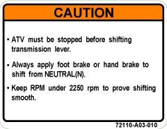

5 (1) (3) (4) (2) (5) 2
6 1. Riding Precautions TE 250 ATV is a special multipurpose four-wheel motorbike with entertainment features. In this section, we will describe important notes and techniques in order for you to safely ride this ATV. Please read this manual thoroughly and spend some time practicing on your new ATV. Pay attention on your safety and that of others. * If you do not have any experience riding an ATV, you can only ride it with instruction by a licensed or qualified instructor. First of all, you have to ride it slowly to feel and adjust yourself to the ATV, even if you are an experienced rider. * Do not attempt to utilize the maximum limits of this ATV. Notes: A. You should familiarize yourself with basic operations of this ATV before you try more difficult operational techniques. B. To ensure the rider s and others safety, anyone who drinks, takes drugs or medicine is not permitted to ride this ATV. The rider s ability to control this ATV will be reduced by the effects of medicine or alcohol. 3
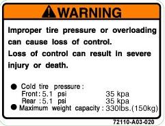
7 Attire Check Before Riding To ensure safety, the rider shall wear a safety helmet, goggles, gloves, boots and protective clothing when riding this ATV. * Conduct a pre-riding check in accordance with Check before riding in user s manual on Page 34 before riding to ensure safety and the service life of this ATV. * Your ability of controlling this ATV will be affected by insufficient tire pressure or a tire that is out of specification. Contact your service center for inspection to reduce the risk of an accident. 4
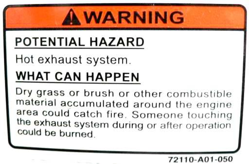
, do not touch these parts. When the ATV is parked, also note that children or passers-by should not touch these parts to avoid injury.")

8 Particular Attention on Parts That May Cause Burn * The exhaust pipe and the engine become very hot when or after the ATV runs for a period of time. To avoid personal injury (including human and objects, etc), do not touch these parts. When the ATV is parked, also note that children or passers-by should not touch these parts to avoid injury. Load Weight Limit Maximum allowable weight for this ATV is 200 kg (two riders) * When you carry loads on the ATV, slow down your speed to increase effective braking distance. * When you carry loads on the ATV, you should keep loads in balance to avoid loss of control of the ATV due to imbalance. Max weight 200 kg * To reduce the risk of fire, do not park this ATV near a dry lawn or flammable substances. Notes: 1. Load weight limit: 200 kg 2. Exceeding the maximum load weight for this ATV may cause an accident. 3. When using this ATV as a trailer, slow down your riding speed. 5
9 Looking At The Terrain * Watch your speed and control technique when you ride on excessively flat, loose and rough surface, and keep an eye on any potential hazards such as pits, water puddles, rocks, root blocks, etc to avoid the risk of an accident. * When riding with poor visibility, e.g. riding at night, turn on the headlight and slow down your speed to ensure safety. * When riding in the area where your viewing angle is limited, e.g. riding on a rough road in hills, it is advisable to attach a flag of some height in the rear of the ATV for warning purposes. This can assure safety for the rider, other riders and onlookers. 6
10 Making Turns When you approach a turn, first slow down and smoothly turn the handlebars to the direction you are going. Also, move your gravity to the outer floor panel and tilt your upper body to the inner side of the turn, which enables your control at the turn to be smoother and safer. Going Uphill Note: When going uphill, move your gravity as forward as possible. Also, sit in the front part of the seat and bend your upper body forward. Keep a steady speed in the uphill process and keep the ATV balanced. Notes: 1. If the slope is too high to proceed and the ATV is moving backward, apply the front brake to slow down and carefully control the ATV to slip down. If it is beyond control, the rider should immediately get off from the left side to avoid the risk of being crushed by the ATV once it turns over. 2. Do not apply only the rear brake to avoid the ATV flipping over. 3. Do not abruptly apply the accelerator. 7
11 Going Downhill Riding Through Water Note: Place your gravity as backward as possible and straighten both of your arms. Keep the ATV in balance and apply the rear brake to slow down your speed. Unless otherwise necessary, do not press the accelerator lever. Do not apply only the front brake to avoid the ATV flipping over. Watch the speed of water current and its depth if riding through water is necessary. If water flows very fast or is deep, the performance of the ATV will be affected, which may cause unsafety to the rider. Notes:. Do not ride across a river with fast current or great depth to avoid loss of control of the ATV and cause risk of hazard to the rider.. After crossing the water area, you should check that the brake function is normal. If it is not, slow down your speed and also intermittently apply both front and rear brakes to restore the brake function.. If it takes a long period of time to ride through the water area and the brake system submerges in water too long, it will lead to loss of brake function. Do not ride this ATV any longer and take it to the nearest service center for inspection and servicing. 8
12 * Smoking is strictly prohibited when refueling the ATV. Turn off your engine when refueling the ATV. * Functionality of the ATV is dependant upon its structure. Any modification without our permission may cause performance degradation and in turn affect the service life of the ATV and riding safety. It is illegal to modify this ATV without our permission. Do not attempt to make any modification. 9
13 2. Naming of Each Component 2 (01) Headlight / position light (02) Front brake handle lever (03) Right front turn signal light (04) Handlebar to lock (05) Left front turn signal light
 Rear light / brake light (08)")
 Exhaust pipe (11) License plate")
 Manual Choke rocker switch 9 10 7 6")
14 (06) Right rear turn signal light (07) Rear light / brake light (08) Ignition switch (09) Left rear turn signal light (10) Exhaust pipe (11) License plate light (12) Battery (13) Accompanying tools (14) Manual Choke rocker switch
 Seat (18) Aux liquid bottle 18")
15 (15) Shift stick (16) Front brake reservoir (17) Seat (18) Aux liquid bottle
 Left footrest (23) Fuel tank cap (24) Throttle Bottom Clamp (25) Right footrest (26) Foot brake (1 for 4 wheel) (27) parking lever (28) Cranking handle (29) Throttle")
16 (30) (27) (21) (29) (23) (28) (22) (19) (20) (24) (26) (25) (19) LCD instrument panel (20) Front brake handle lever (21) High/low beam switch Startup rocker switch Warning light switch Turn signal light switch Horn switch (22) Left footrest (23) Fuel tank cap (24) Throttle Bottom Clamp (25) Right footrest (26) Foot brake (1 for 4 wheel) (27) parking lever (28) Cranking handle (29) Throttle (30) Power Supplier-12V 13
17 3. Operation of Each Component Ignition switch OFF : At this position, power supply to the ATV is completely cut off. The key can be removed. (The engine stops) ON : At this position, power supply to the ATV is connected. The key cannot be removed at this position. (The engine can be started up.) : At this position, power supply to the ATV is connected. The key cannot be removed and the position light comes on. (The engine can be started up.) Reverse Indicator Light: 1. The reverse indicator light comes on (red light) when you turn on the ignition switch, when the transmission is at the reverse gear. 2. Neutral Indicator Light: The neutral indicator light comes on (green light) when you turn on the ignition switch, when the transmission is at the neutral position (1) Key hole (2) Key Note: Do not turn the key to the OFF position while riding. This is the major cause of an accident. Note: When starting the engine, the transmission should be at the neutral position to avoid any risk of hazard. 14
18 3. High Beam Indicator Light: When this light comes on, the headlight is using high beam light. 4. Temperature Indicator Light: When this light comes on, it means the engine temperature is too high. Check the coolant level in the Aux Liquid Bottle Left/Right signal indicator: When operating the Left/right turn signal light switch, this indicator will come on. 6. Fuel level indicator: When the pointer of the fuel level indicator rests near the last scale, the fuel remaining in the tank is about 1.8 liters. Refuel with 95 unleaded gasoline as early as possible Note: *When the engine over-temperature indicator light comes on, you must stop the engine and let it cool down. Note: There is no need to add any additive to the fuel when refueling. Addition of any additive in fuel may cause engine failure. 15
 : At this position, the headlight comes on and the light is beaming at a far distance. (The headlight will not come on if the ignition switch is not turned on.")
19 Headlight Switch Startup Rocker Switch : At this position, the headlight comes on and the light is beaming at a short distance. (The headlight will not come on if the ignition switch is not turned on.) : At this position, the headlight comes on and the light is beaming at a far distance. (The headlight will not come on if the ignition switch is not turned on.) When the engine is started electrically, be sure to pull tight the front or rear brake handle lever to energize the system. Then the engine can be started while pressing the startup rocker switch. 16


20 Accelerator Lever The speed of the ATV is controlled via the accelerator lever. The ATV speed increases when pressing the accelerator lever using your thumb. Press the accelerator lever slowly. When starting the engine or riding uphill, press the accelerator lever slowly, the engine revs up and produces more power. To reduce the speed, release the accelerator lever. Accelerator Limiting Device To protect a new rider who is not familiar with this ATV from an accident, this ATV is fitted with an accelerator limiting device that can adjust the travel of the throttle valve, which in turn limits engine power. Adjustment:.Loosen the retaining nut, and then turn the adjusting screw with a screwdriver rider. Turning clockwise will reduce the travel of the throttle valve, while turning counterclockwise will increase the travel and increase the engine power up to its maximum..when the appropriate engine power is reached, tighten the retaining nut again. (2) (1) Note: *The play of the accelerator lever should be 1 to 4 mm, which can avoid jerking ahead when the engine is started. ( (1) Retaining nut (2) Adjusting screw 17
 Shift Stick To make the ATV to stop, move forward, or reverse, use the shift stick to")
21 Manual Choke Rocker Switch. When the engine starts to cool, the engine can be easier to start up with the choke switch being pushed leftward..after the engine warms up for 2-3 minutes, push the rocker switch back to its original position (push rightward) Shift Stick To make the ATV to stop, move forward, or reverse, use the shift stick to shift gears. (With pulling and releasing the rear brake handle lever) N: At this position, the gear is in neutral. (The shift stick must be at this position when the ATV is stopped or started) D: At this position, the engine is in forward gear. (The ATV moves forward) R: At this position, the engine is in reverse gear. (The ATV moves backward.) 18 Note: *The shift stick should be placed at the N position, when the engine starts up or stops to avoid the risk of hazard. *After the engine starts up, and when operating the shift stick, you should also pull the rear brake handle lever, or the engine will stop. This serves as a safe interrupting system.

22 Parking Lever (Rear Brake) How to use it: Turn the rear brake lever to the left side tightly. How to release it: Pull parking lever to the right side,it will return automaticto it s position,the rear brake will be relieved at the same time. Flagpole Holder This allows you to position the desired flags in the holder. Note: *When starting the engine or parking the ATV, apply the parking lever to lock the rear wheels to prevent the ATV from moving and causing the risk of hazard. *If the play of the brake handle level is incorrect, the rear wheels may not be locked, which may cause the risk of a hazard. 19


23 Seat lock The seat can be removed. The battery, fuses, and tool kit are located under the seat. How to remove the seat: Pull the locking lever rightward, and then lift rear part of the seat backward. Now the seat can be removed. How to mount the seat: Push the retaining tab under the front seat into the holder on the frame. Then push downward the rear part of the seat, and the seat can be attached on the frame. Note: *After the seat is mounted, you need to ascertain that it is firmly attached to the frame by moving it upward/downward, and forward/backward. If the seat is not firmly attached, it may cause the rider to lose control of the ATV and lead to an accident. 20

24 Steering Handle Lock To prevent thefting, the handlebars can be locked when the ATV is parked. How to lock the handlebars: Turn the handlebars to the left all the way until it stops, and then turn the key clockwise to lock the handlebars. Then, remove the key. How to unlock the handlebars: Turn the key counterclockwise to unlock the handlebars, and then remove the key. LOCK UNLOCK Notes: * After the handlebars are locked, verify that they are really locked by slightly turning them. *After the handlebars are unlocked, verify that they are really unlocked by rotating the handle. This can prevent risk of hazard when riding. 21

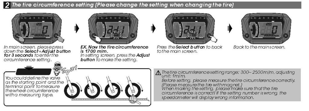
25 LCD Instrument Panel Adjustment 22
26 23
 Pull tight the front or the rear brake handle lever, or step on the brake pedal.")

27 4. Starting the Engine Electrically (1) Before starting the engine, first check oil and fuel levels.. Turn the ignition switch to the ON position. (2) Pull tight the front or the rear brake handle lever, or step on the brake pedal. Note: When starting the engine, the ignition circuit for the electric startup can only be energized with actuation of the startup switch in combination with the front or the rear brake handle lever being pulled tight or the brake pedal being depressed. (1) Key hole (2) Key Note: *When the ignition switch is turned on, check that the neutral indicator light comes on. The gear should be in neutral when the engine is started. 24

28 When Starting The Engine. Press the startup rocker switch, and the engine can be started.. If the engine starts to cool, let the engine warm up for 2-3 minutes.. Do not rev the engine to high speed while it is idling. This can ensure the engine life. Notes: *Once the engine starts to run, immediately release the startup rocker switch. *Do not press the startup rocker switch while the engine is running, or it will lead to an adverse effect to the engine. *Do not press the startup switch for over four seconds, when the electric motor is used to start the engine.. If the ATV has been stored for a long time or when the fuel tank is empty, it is very likely that you can not start the engine even if the fuel tank has been topped up. Now, you should drain fuel in the carburetor by loosening the draining screw using a screwdriver, and then restart the engine. Smoking is strictly prohibited when draining fuel. When The Engine is Difficult to Start:. If the engine does not start within 3-4 seconds after pressing the startup switch, you may need to push the choke lever to the left, which can help engine start up. Note: Note: *After the engine warms up for 2-3 minutes, you must push the choke lever back to its original position. Otherwise, the engine speed will be affected. *After draining fuel in the carburetor, remember to tighten the draining screw. Otherwise, this can cause hazard due to fuel leakage. 25


29 5. Starting by Manual Cranking The cranking handle is located at the ATV mechanism to the left side of the engine. It is used to manually start the engine, as the battery power is too low to start the engine. 1. Turn counterclockwise and release the cranking handle from its retaining groove. 2. Pull the handle promptly all the way to its full length. 3. When the engine starts to run, turn the handle clockwise and lock it into its retaining groove. Note: Do not let water enter the ATV mechanism. Lock the cranking handle back to its retaining groove after it is used. 26

30 6. Normal Usage When riding: The rear brake handle lever is kept at the braking position, and then put the shift stick to the D or R position. * The rider shall put both of his feet on floor panel and keep his body upright with two hands holding the handlebars. Do not make haste, relax, carefully heed surrounding conditions and ride safely. Note: *When the engine is idling, do not push the accelerator to rev the engine. Note: *Before riding, the rear brake handle levers should be kept at braking positions. 27


31 Placing the parking lever back to its original position (OFF) is in the brake releasing (unlocking) status. Release the rear brake handle lever, and slowly push the accelerator lever, the ATV will start to run smoothly. Note: *After releasing the parking brake on the rear wheels, do not push or press the accelerator lever to avoid jerking ahead and causing the risk of hazard. Note: *Do not push the accelerator with force to avoid dash-out of the ATV. 28
32 Normal Riding Make sure that the surroundings are safe before setting out on the trip. (See Riding Precautions) The speed of the ATV is controlled via the accelerator lever. Pushing the accelerator lever... the speed increases The accelerator lever should be pushed slowly. When going uphill, slowly push the accelerator lever the engine will rev up and power increases. Return to original position... the speed decreases. 29
33 Prolonged Engine Life Depends Upon Correct Riding Keep the ATV speed no more than 40 km/h during the first month when new ATV starts to operate. (Engine running in period) When Applying Brakes, Simultaneously Apply Both Front and Rear Brake Handle Levers. * After returning the accelerator lever back to its OFF position, firmly hold the brake handle levers and step on foot brake. * Ideally, when applying brakes, start to slowly pull the brake handle levers and then pull them firmly to the end. Notes: *Care should be taken if applying only one brake handle lever on one side, it is easy to cause the ATV to skid and be unstable. *Do not attempt to apply emergency brakes during riding, it is easy to cause the ATV to skid, and is very dangerous for the rider. 30


34 Do Not Apply Emergency Brake and Have a Quick Turn Using emergency brakes and quickly turning are two major causes to lead to skidding and turning over, which is very dangerous for the rider. Riding with Particular Attention in Raining Days * In raining days the condition of road surface differs from that in clear days. The brake distance will be extended. Ride at a lower speed and apply brakes earlier. * When going downhill, put the accelerator lever back to the OFF position and intermittently apply brakes. Ride at a slower speed. 31

35 How to Stop the ATV When approaching the parking space: * Check that the surroundings are in safe condition and then slowly park the ATV. * Put the accelerator lever back to the original position, and pull both front and rear brake handle levers, which will activate the brake light to alert coming ATVs in the back. When the ATV Comes to a Full Stop Put the shift stick at the N position and turn the ignition switch to the OFF position. (1) Key hole (2) Key Note: *Turning off the ignition switch and removing the key during riding will cause the electrical system to disable. This is a major cause of an accident. Do not do that until the ATV comes to a full stop. 32

36 When parking the ATV: * To prevent the ATV from moving, pull tight the brake handle lever and push the parking lever to the ON position (leftward) to lock the rear wheels. When transporting the ATV: * First drain fuel in the tank and the carburetor. * Loosen the draining screw of the carburetor. Use a container to keep drained fuel. * After the fuel is drained, tighten the draining screw. Draining screw Note: *If the play of the rear brake handle lever is incorrect, it will not lock the rear wheels, which will lead to the risk of hazard. Note: *Smoking is strictly prohibited when draining fuel. 33


37 7. Check Before Riding Pre-riding Check Make it a habit to check the ATV before riding. For safety reason and to prevent malfunction and an accident from happening, it is necessary to have a pre-riding check. Even for a relatively simple and easy trip, a pre-riding check is also required. If an abnormality is found, ride your ATV to the nearest workshop or service center for inspection and repair. Oil Check and Refilling * Oil level check 1. Start the engine and let it warm up for 2-3 minutes. Then turn off the ignition switch for 2-3 minutes. Visually check the oil window. 2. If the oil level is at the lower limit, refill oil until the level reaches the upper limit. HI LOW Notes: *If the ATV is parked on a tilted surface or the engine just stops, the oil level will not be accurate. *When the engine stops, it is still very hot. If you check the oil level or replace oil right after, care should be taken to avoid being burn. 34
38 Recommended Oil Specification and Grade Oil specification: SAE 15W40# API.SG/CD or above Engine oil grade: SG/CD or above certified by API (American Petroleum Institute) Oil capacity: Full capacity: 1.6 liter Replacing volume: 1.4 liter Note: *To prevent using low-grade oil, it is recommended you go to a workshop of the dealer from whom you purchased your ATV or the service center for oil change. 35


39 Changing Oil * 1. Start the engine and let it warm up for 2-3 minutes, and then turn off the ignition switch and remove the oil filling cap. 2. Remove the oil pan drain plug at the bottom of the engine. Turning clockwise the plug to tighten it, and turn counterclockwise to loosen it. Use a container to keep the drained oil. 3. After oil is drained up, tighten the oil pan drain plug. Then, fill in correct oil with appropriate volume. 4. Visually check that the oil level is between the upper and lower limits. Then, tighten the oil filling cap. 5. The tightening torque for the oil pan drain plug is 3.0 kg-m. Oil filling cap Oil pan drain plug Note: *To reduce the risk of getting burn, do not change oil when the engine is still very hot. 36

40 Fuel Check and Refueling * Refuel Unleaded #92 or 95 as early as possible * How to use the fuel cap: 1. First stop the engine 2. Turning the cap clockwise you can open the cap, while turning counterclockwise you can tighten the cap. 3. When starting the engine, turn the ignition switch from the OFF to ON position. Notes: * Smoking is strictly prohibited when refueling the ATV. * Stop the engine before refueling. * No need to add any additive in fuel when refilling. Addition of any additive may cause engine failure. * Do not top up fuel to the opening. Otherwise, fuel may spill as it may expand by heat or sunlight and lead to the risk of hazard. (1) Key hole (2) Key 37


41 Front and Rear Brake Fluid Level Check and Refilling * Brake fluid level check 1. Position the handlebars in the middle. Check front and rear brake fluid levels in the reservoirs. Fluid level should be between upper and lower limits. 2. When the fluid level drops to the lower limit, check the condition of the brake shoe wear. 3. If the brake shoe wear is within the specified limit, then it normally represents that there is leakage in the system. Ride your ATV to the dealer s workshop or service center for inspection. * Brake fluid refilling 1. Position the handlebars in the middle. Remove two fixing screws on the cover of the brake fluid reservoir, and then take out the cover. 2. Refill brake fluid, recommended DOT-4 grade, until it reaches the upper limit. Then, position back the cover and tighten two fixing screws. 3. Change brake fluid once a year. Notes: * Do not mix brake fluid of different brands or grades, which may lead to brake failure and the risk of hazard. * When changing brake fluid, cover the painted area with cloth to prevent painted surface from being damaged by brake fluid. 38


42 Is Brake Performance Good? Ride slowly to verify that the front and rear brake performance is good. Brake Light Check * Turn the ignition switch to the ON position. * Pull both the front and rear brake handle levers to make sure that the brake light illuminates. * Check that the brake light housing is clean or damaged. 39


43 Headlight Check * Turn the ignition switch to ON position. * Operate the headlight switch and check that the high beam or low beam illuminates. * Check that the headlight housing is clean or damaged. Headlight Beaming Distance Adjustment Headlight s beaming distance is adjustable. How to adjust it: Turn on the ignition switch and also turn on the headlight switch. Then screw in or out the adjusting screw to adjust the beaming distance. 40


44 Tire Check * Is tire pressure OK? * See the following table when checking tire pressure. Front wheel Rear wheel Recommended standard value kgf/cm PSI 0.28 kgf/cm PSI Lower limit 0.25 kgf/cm PSI 0.25 kgf/cm PSI Upper limit 0.35 kgf/cm 2 5 PSI 0.35 kgf/cm 2 5 PSI * If metal chips or small stones are found in tire grooves, remove them before riding. * If tire crack is found or tire wear exceeds the prescribed limit, immediately change the tire. * If tire groove depth is less than 3mm, immediately change the tire. 41


45 Front And Rear Shock Absorber Check Put your weight on the handlebars and rear hand rest and shake them upward/downward to check that the shock absorbers are OK. Rear Shock Absorber Adjustment To ensure riding comfort, the travel of rear shock absorber is adjustable. How to adjust it: 1. Using a wrench to loosen the retaining nut and adjust the absorber travel. 2. Turning counterclockwise the retaining nut is to increase the travel, and turning clockwise is to reduce the travel. 3. Tighten the retaining nut again after a proper travel is obtained. 42

46 Transmission Chain Check and Adjustment The chain between two sprockets should have 3 cm clearance. How to adjust: * Loosen the fixing bolt of the rear wheel hub. Use a screwdriver to hold the rear wheel hub and the ride sprocket so that the ATV will not move. * While pushing the ATV forward will loosen the chain, pulling backward will tighten the chain. Adjust the chain until it has reached 3 cm clearance for upper and lower chain. * Tighten the fixing bolt again. 43

47 To refill coolant, normally do not open the radiator cap when the engine is still hot. 1. Park the ATV on a flat surface with stand. 2. Open the Aux Liquid Bottle and refill coolant until the level reaches the upper limit. * If the coolant level drops significantly, it usually represents a problem in the system. * Recommended anti-freeze: Te-she Anti-freeze Name Prescribed concentration Anti-freeze 30%(50% in cold zone) Concentration and anti-freeze temperature -12 : 25% -15 : 30% -24 : 40% -35 : 50% Notes: * Use soft water to mix with anti-freeze * Note that low grade coolant will shorten the radiator service life * Under normal conditions, coolant should be replaced once a year or every 10000km. 44


48 Changing Coolant Notes: * Care should be taken when opening the radiator cap, as coolant may be very hot with high pressure. Steam may cause burn and hazards. Wait until the radiator cools down. Use a piece of cloth to cover the cap and slowly open it. * In case that coolant drips on the painted surface, immediately rinse it with clean water. Radiator cap <How to drain coolant> 1. First remove the front cover 2. Push downward the radiator cap and turn counterclockwise to open the cap. 3. Remove the draining bolt and let coolant drain out. Tilting the ATV rightward may facilitate coolant to drain faster. 4. Take out the Aux Liquid Bottle and pour out coolant. Draining bolt 45
49 Filling Coolant 1. Position the draining bolt and Aux Liquid Bottle in place. 2. First fill up the radiator and then the Aux Liquid Bottle until the coolant level reaches the upper limit. 3. Ensure that the radiator cap and Aux Liquid Bottle cap are firmly closed 4. Start the engine and let the radiator fan run more than two times. Then stop the engine. (Be sure to wait until the radiator cools down before opening the cap, to avoid getting burnt.) 5. Open the radiator cap and check that coolant level is still at the upper limit, if not, refill coolant and then firmly tighten the cap. 6. Start the engine again and let it run for 1-2 minutes. Open the radiator cap and check that the coolant level is still at the upper limit, if not, refill coolant again. Keep repeating this procedure until coolant level can retain at the upper limit. 46
 SAE 90# Gear oil Tightening torque for the draining bolt of gear oil is 2.45 kg-m Tightening torque for the filling cap of gear oil is 2.")

50 Changing Gear Oil (Drain period) For a new ATV, the drain period is one month, and then change the gear oil every six months afterwards. (Recommended gear oil) SAE 90# Gear oil Tightening torque for the draining bolt of gear oil is 2.45 kg-m Tightening torque for the filling cap of gear oil is 2.45 kg-m (1) Gear oil filling cap Gear Oil Capacity Full capacity: 1.0 Liter Regular replacement volume: 0.8 Liter How to change: 1. Start the engine and let it warm up for 2-3 minutes. Turn off the ignition switch and remove the filling cap of gear oil. 2. Remove the draining bolt at the bottom of the engine. Turning clockwise is to tighten the bolt, while turning counterclockwise is to loosen the bolt. Use a container to keep the drained gear oil. 3. After draining up gear oil, tighten the bolt again. Fill in correct gear oil with appropriate volume. 4. Then, firmly tighten the filling cap to avoid oil seeping. (2) Gear oil draining bolt Notes: Change gear oil more frequently under the following conditions: * Often riding in rain * Usually operating for long hours or long trip * Riding under heavy load 47

 1. Remove the seat 2.")


51 How to Replace the Air Cleaner exceed two-thirds of the pipe length. A dirty air cleaner is the major causes of engine power drop and high fuel consumption. The air cleaner for this model is a wet sponge type. Check and replace the air cleaner every three months. (How to replace it) 1. Remove the seat 2. Unclip two fixing clips on the air cleaner cover and remove the air cleaner cover. 3. Loosen the screw and take out the cleaner core. 4. Replace the air cleaner core. (How to mount it) *To mount it, take the reverse steps as above for replacing it. Notes: * If the air cleaner is not mounted correctly, dirt/dust may directly be drawn in the cylinder, causing engine wear, power drop and resulting in shorter engine life. * Do not wet the air cleaner when washing the ATV. Wet air cleaner may cause the engine to be difficult to start. * Check and replace the air cleaner at a shorter period under the following conditions: 1. Often riding in rain 2. Often riding on the dusty road surface. Fixing clips Air cleaner cover Screw Air cleaner core Clip Oil collecting pipe Note: Regularly drain off the accumulated oil in the oil collecting pipe under the air cleaner. Do not let accumulated oil 48


52 Spark Plug Check Dirty pole or too wide a gap will cause incomplete sparking. <How to clean it> * Ideally, use a spark plug cleaner to clean it. * Or, use a needle brush to clean it. <Adjustment> * The gap between two poles normally is mm as shown in Figure A. (N.G.K) DPR7EA-9 Do not use a spark plug other than a recommended one. Note: When the engine stops, it is still very hot. Be careful not to get burnt. First put the spark plug with hand tight, and then tighten it using a spark plug spanner. 49
53 Simple Maintenance If check results show that cleaning, adjustment and replacement are required. Conduct those operations in accordance with the description in the regular check record. Notes: Ensure safety when serving the ATV: * Use suitable tools. * Make preparation while the engine stops. * When the engine stops, the engine and exhaust pipe are still very hot. Care should be taken to avoid getting burnt. 50
54 Regular Maintenance Table Emission control system, checklist for serving items and timetable: For riding safety, keeping performance, prolonging ATV life, and reducing exhaust emission, you should inspect those service items for routine maintenance. I: Inspect, and clean, lubricate, refill, adjust or replace if required A: Adjust C: Clean R: Replace T: Tighten Month km km km km km km km km km km 0 km 0 km 0 km 0 km 0 km 0 km Remarks Lubrication System Engine oil Oil strainer R C I R C R R R C R R R R R C R R R R R C I: Inspect Gear oil R R R R Fuel supply Gasoline filter I I system Fuel strainer C C Carburetor A A Fuel pipe I I Air supply system Air cleaner R R Secondary air cleaner R R Secondary air inlet system pipe I Air inlet manifold screws I Control related air pipe I I Catalyst converter I I Transmission system Cam chain (4T) I I Transmission chain (M/C ATV) I I Ride belt I I Valve gap (4T) I I Ignition system Spark plug/ 4T R C.D.I I I Ignition circuit I I Others Important body bolts T T A T A T A T A T A T T A T Brake system A A T A T A T A T A T A A T A A: Adjust C: Clean R: Replace T: Tighten *If cleaning, lubrication, refill, adjustment, or replacement are found necessary during riding or inspection, you can take corrective actions directly provided that exhaust emission is not seriously affected. However, it these have seriously affected exhaust emission, these corrective actions will not be conducted until they are reported for approval. (2) Maintenance other than planned schedule Item Cause for maintenance Ignition system If abnormal ignition, engine over-heat, engine stall are found, immediately perform inspection. Removing Deposit If engine power reduces significantly after operation of ten to fifteen months Transmission system If power reduces significantly when accelerating after operation of ten to fifteen months Piston If the engine is under severe load in the first month since operation, the piston, piston rings, cylinder may wear or get stuck. The engine should be cleaned or honed. Some parts may be renewed. 51


55 Battery Electrolyte Check 1. The battery for this model is a servicing-free type without need of refilling battery electrolyte. Notes: * Do not open the cover of the enclosed battery that contains battery electrolyte * If the ATV has not been used for a long period of time, the battery may have discharged and reduced its power. In this case, remove the battery and recharge it to its full power and then put it in a cool and well-ventilated place. * If the ATV will not be used for a long period of time, remove the connecting wire at the negative pole. 2. Battery stud terminal Remove the seat before cleaning the battery stud terminals. * If the stud terminal becomes corroded, remove the battery and clean it thoroughly. * After cleaning the stud, you may apply a thin layer of grease or Vaseline. Then, position the battery in place and attach the connecting wires. (1) Battery tie band (2) Positive pole (3) Negative pole (4) Fuse box (5) Battery (6) Relay Notes: * While removing or mounting the battery, do not allow flammable gas to get close. * To remove the battery, first turn off the ignition switch. Then first detach the negative(-) connecting wire. However, to connect the battery, first attach the positive(+) wire and then the negative(-) wire. * If the terminal screw becomes loose, tighten it firmly. 52
56 Replacing the Fuse Turn off the ignition switch and check if the fuse is blown. When replacing the fuse, always get a fuse of the specified rating. * Before replacing the fuse, first find out why it is blown. * Remove the seat * The fuse is located behind the battery * To remove the fuse: Open the fuse box and take out the blown fuse. If the fuse is not well in contact, it will create heat and easily leads to circuit failure. * To assemble it: Insert the fuse in the holder and position the cover back in place. Be sure to gently pull the fuse to ascertain that the fuse has good contact. A loose fuse will generate heat. Fuse rating: 10A, 15A and 30A. * To replace the battery (lamps), use only the original components of the prescribed specification. * If components are not original or out of specification, the fuse can easily be blown, and the battery will not be in balanced status. When washing the ATV, do not wash it with high-pressure water jet. Notes: * To remove the fuse: Care should be taken when removing the fuse, as its holder is very small. If the fuse does not have good contact after opening the cover, it may generate heat and lead to circuit failure. * To assemble the fuse: Insert the fuse in its holder. Be sure to gently pull the fuse to ascertain that the fuse is well in contact. A loose fuse will generate heat. 53
57 Lubricating Each Part of the ATV Visually check that all parts that need lubrication are sufficiently lubricated. 54
58 When Failure Occurs If ATV experiences a malfunction during use, please take it to a dealer or service center for inspection. If The Engine Stops If the engine stops during riding, first check the following; * Is fuel available? * The way to start the engine is correct * Any failure occurs on other part 55
59 Specifications TE 250-U Item Specification Engine type One cylinder, Liquid cooling, four stroke Displacement 249.4cc Compression ratio 11.0 Bore X Stroke 71x63 Max. Power 12.9 kw at 7000 min -1 Max. Torque 20.8 Nm at 3500 min -1 Transmission type CVT Fuel tank capacity 14.8 L Oil replacement volume 1.6 L Net Weight 255Kg Overall Length 2060mm Overall Width 1215mm Overall Height 1210mm Wheelbase 1270mm Tire size Front: 25x8-12 Rear: 25x10-12 Starting method Hand-pull start /electric start Ignition method C.D.I TE 300-U Specification One cylinder, Liquid cooling, four stroke 280.2cc x kw at 7000 min Nm at 5500 min -1 CVT 14.8 L 1.6 L 255Kg 2060mm 1215mm 1210mm 1270mm Front: 25x8-12 Rear: 25x10-12 Hand-pull start /electric start C.D.I 56
AX600 EFI 4x4 OWNER S MANUAL
 AX600 EFI 4x4 OWNER S MANUAL P/N 72117-A40-000 Dear Customers, Thank you for purchasing AX600U 4x4 EFI. This manual describes detailed instructions of correct operation, maintenance and adjustment of AX600U
ATV-320 R OWNER S MANUAL
 ATV-320 R OWNER S MANUAL FOREWORD May we, the manufacturer, take this opportunity to thank you for choosing our ATV to serve you. This Owner s Manual is prepared for you to properly operate in safety.
ATV-320 S/U ATV-320SD S/U OWNER S MANUAL V
 ATV-320 S/U ATV-320SD S/U OWNER S MANUAL V1.0 2014.03.01 0 FOREWORD May we, the manufacturer, take this opportunity to thank you for choosing our ATV to serve you. This Owner s Manual is prepared for you
1.CONTENTS 1. Contents Control location Before riding Safe riding Driving Use genuine spare parts Use
 1.CONTENTS 1. Contents... 1 2. Control location... 3 3. Before riding... 4 4. Safe riding... 4 5. Driving... 5 6. Use genuine spare parts... 5 7. Use of each component... 6 Gauges... 6 Operation of ignition
NOTES FOR SAFETY OPERATOR-ONLY.
 NOTES FOR SAFETY Both the parents and their child must fully understand everything in this manual before riding. This vehicle is for OPERATOR-ONLY. This vehicle is only designed for operation on level,
3. INSPECTION/ADJUSTMENT
 3 3 INSPECTION/ADJUSTMENT SERVICE INFORMATION -------------------------------------------- 3-1 MAINTENANCE SCHEDULE ---------------------------------------- 3-2 FUEL LINE/FUEL FILTER -------------------------------------------
SECTION 8 2 DO IT YOURSELF MAINTENANCE. Chassis
 DO IT YOURSELF MAINTENANCE Chassis SECTION 8 2 Checking the coolant level of the traction motor................ 184 Checking the radiator....................................... 185 Checking brake fluid........................................
INSPECTION/ADJUSTMENT
 3 3 INSPECTION/ADJUSTMENT SERVICE INFORMATION----------------------------------------------------------------------- 3-1 MAINTENANCE SCHEDULE-------------------------------------------------------------------
ATV-50/90/100 I/II/V OWNER S MANUAL
 1 ATV-50/90/100 I/II/V OWNER S MANUAL FOREWORD May we, the manufacturer, take this opportunity to thank you for choosing our ATV to serve you. This Owner s Manual is prepared for you the details as to
May we, the manufacturer, take this opportunity to thank you for choosing our ATV to serve you.
 FOREWORD May we, the manufacturer, take this opportunity to thank you for choosing our ATV to serve you. This Owner s Manual is prepared for you the details as to operate and maintenance necessarily to
BT49QT-9O3 User s Manual
 BT49QT-9O3 User s Manual Preface Thank you very much for purchasing BAOTIAN brand motorcycle of model BT49QT-9O3, which developed by BAOTIAN MOTORCYCLE INDUSTRIAL CO., LTD. And welcome to join the driver
Light condition and operation Windshield glass condition Wiper blade condition Paint condition and corrosion Fluid leaks Door and hood lock condition
 GENERAL CHECKS Engine Compartment The following should be checked regularly: Engine oil level and condition Transmission fluid level and condition Brake fluid level Clutch fluid level Engine coolant level
SECTION 6 2 SERVICE PROCEDURES AND SPECIFICATIONS. Engine. Specifications
 SERVICE PROCEDURES AND SPECIFICATIONS Engine SECTION 6 2 Specifications........................................... 170 Fuel.................................................... 172 Facts about engine oil
Part 7 DO IT YOURSELF MAINTENANCE
 Part 7 DO IT YOURSELF MAINTENANCE Chapter 7 2 Engine and Chassis Checking the engine oil level Checking the engine coolant level Checking brake fluid Checking power steering fluid Checking tire pressure
SECTION 6 2 SERVICE PROCEDURES AND SPECIFICATIONS. Engine. Specifications
 SERVICE PROCEDURES AND SPECIFICATIONS Engine SECTION 6 2 Specifications........................................... 162 Fuel.................................................... 164 Facts about engine oil
Operation and Maintenance Instructions
 X-Treme TM Electric Moped Operation and Maintenance Instructions Electric Moped XM-3100 Revised 11/6/08 Operation and Maintenance Instructions We strongly recommend that you read this entire manual before
Owner s/operator s Manual
 Water Pump MP2533E2 Owner s/operator s Manual Completely read and understand this manual before using this product. Foreword This Owner s/ Operator s Manual is designed to familiarize the operator with
3. INSPECTION/ADJUSTMENT
 SERVICE INFORMATION...3-0 FINAL REDUCTION GEAR OIL...3-7 MAINTENANCE SCHEDULE...3-2 DRIVE BELT...3-7 FUEL FILTER...3-3 BRAKE SHOE...3-8 THROTTLE OPERATION...3-3 BRAKE ADJUSTING NUT...3-8 AIR CLEANER...3-4
3. INSPECTION/ADJUSTMENT
 3 SERVICE INFORMATION...3-0 FINAL REDUCTION GEAR OIL...3-7 MAINTENANCE SCHEDULE...3-2 DRIVE BELT...3-7 FUEL FILTER...3-3 BRAKE SHOE...3-8 THROTTLE OPERATION...3-3 BRAKE ADJUSTING NUT...3-8 AIR CLEANER...3-4
CONTENT. 3. Maintenance
 CONTENT Foreword -------------------------------------------------------------------------------------------- 1 1. The performance, technical parameters and structure of Go Kart--------------------------------------------2
SECTION 1 7 OPERATION OF INSTRUMENTS AND CONTROLS Ignition switch, Transmission and Parking brake
 SECTION 1 7 OPERATION OF INSTRUMENTS AND CONTROLS Ignition switch, Transmission and Parking brake Ignition switch.............................................. 114 Automatic transmission.....................................
1200W INVERTER GENERATOR
 1200W INVERTER GENERATOR MODEL NO: IG1200 PART NO: 8877070 OPERATION & MAINTENANCE INSTRUCTIONS LS0117 INTRODUCTION Thank you for purchasing this CLARKE 1200W Inverter Generator. Before attempting to use
RASER R1/ RASER FX OWNER'S MANUAL
 RASER R1/ RASER FX OWNER'S MANUAL IMPORTANT NOTES FOR SAFE OPERATION FAILURE TO FOLLOW THE INSTRUCTIONS CONTAINED HEREIN MAY RESULT IN DAMAGE TO YOUR SCOOTER, DECREASE ENGINE LIFE, CAUSE INJURY TO YOURSELF
SECTION 7 2 DO IT YOURSELF MAINTENANCE MR2 U. Engine and Chassis
 SECTION 7 2 DO IT YOURSELF MAINTENANCE Engine and Chassis Checking the engine oil level................................. 168 Checking the engine coolant level............................ 169 Checking brake
RedGum GP160 Splitter. Owner s Manual
 RedGum GP160 Splitter Owner s Manual Product Description & Intended Purpose: This Log Splitter / Wood Splitter is an outdoor product that splits wood logs for use as fuel in a fireplace or a woodstove.
Gasoline Inverter Generator
 user manual Gasoline Inverter Generator table of contents Preface Introduction... Safety Information Exhaust fumes are poisonous... Fuel is highly flammable and poisonous... Engine and muffler may be hot...
2.CONTROL LOCATION MODEL: ORBIT II 125(AE12W1-6)
") 1.CONTENTS 1. Contents... 1 2. Control location... 3 3. Before riding... 4 4. Safe riding... 4 5. Driving... 5 6. Use genuine spare parts... 5 7. Use of each component... 6 Gauges... 6 Operation of ignition
1.CONTENTS 1. Contents... 1 2. Control location... 3 3. Before riding... 4 4. Safe riding... 4 5. Driving... 5 6. Use genuine spare parts... 5 7. Use of each component... 6 Gauges... 6 Operation of ignition
WARNING - BEFORE YOU DRIVE
 See back cover for a pre-ride checklist section 3 operation WARNING - BEFORE YOU DRIVE 1. Always perform a pre-ride inspection of the vehicle using the checklist provided on the back cover of this manual.
MOTORINI GP 50. User s Manual.
 MOTORINI GP 50 User s Manual www.motorini.co.uk Dear user: Thank you for choosing to buy a Motorini GP 50 This manual provides the correct operation and maintenance methods for safe riding and maintaining
AIR-COOLED DIESEL GENERATOR OWNERʼS MANUAL. This manual contains important safety information. TDG2500E TDGW7000E TDG7000SE TDG4500E
 AIR-COOLED DIESEL GENERATOR OWNERʼS MANUAL This manual contains important safety information. TDG2500E TDGW7000E TDG7000SE TDG4500E TDG8000-3 TDG7000SE-3 TDG7000E TDG8000E TDGW7000SE TDG7000E3 TDGW8000E
3. INSPECTION/ADJUSTMENT
 3 3 INSPECTION/ADJUSTMENT SERVICE INFORMATION-------------------------------------------------- 3-1 MAINTENANCE SCHEDULE---------------------------------------------- 3-3 FUEL LINE---------------------------------------------------------------------
1100W PORTABLE GENERATOR
 1100W PORTABLE GENERATOR MODEL NO: G1200 PART NO: 8010110 OPERATION & MAINTENANCE INSTRUCTIONS LS0312 INTRODUCTION Thank you for purchasing this CLARKE 1100W Portable Generator. Before attempting to use
WEBER CARBURETOR TROUBLESHOOTING GUIDE
 This guide is to help pinpoint problems by diagnosing engine symptoms associated with specific vehicle operating conditions. The chart will guide you step by step to help correct these problems. For successful
PCBL 1600/1800 POWER WHEELCHAIR MODERN USER'S MANUAL Edition
 PCBL 1600/1800 POWER WHEELCHAIR MODERN USER'S MANUAL Edition 09.2013 mdh sp. z o.o. 90-349 Łódź, ul. Tymienieckiego 22/24 tel. (+48) 42 212 32 08 fax: (+48) 42 674 04 99 www.mdh.pl viteacare@mdh.pl 1 TABLE
Brake System H TX, H2.0TXS [B475]; H TX [B466] Safety Precautions Maintenance and Repair
![Brake System H TX, H2.0TXS [B475]; H TX [B466] Safety Precautions Maintenance and Repair](/thumbs/86/93834005.jpg "Brake System H TX, H2.0TXS [B475]; H TX [B466] Safety Precautions Maintenance and Repair") HMM180001 Brake System H1.5-1.8TX, H2.0TXS [B475]; H2.5-3.5TX [B466] Safety Precautions Maintenance and Repair When lifting parts or assemblies, make sure all slings, chains, or cables are correctly fastened,
HMM180001 Brake System H1.5-1.8TX, H2.0TXS [B475]; H2.5-3.5TX [B466] Safety Precautions Maintenance and Repair When lifting parts or assemblies, make sure all slings, chains, or cables are correctly fastened,
CHASSIS CONTENTS EXTERIOR PARTS 6-1 FRAME COVER 6-2 REAR FRAME COVER 6-4 FRONT WHEEL 6-6 FRONT BRAKE 6-10 HANDLEBARS 6-17 FRONT FORK 6-19
 CHASSIS CONTENTS EXTERIOR PARTS 6- FRAME COVER 6- REAR FRAME COVER 6-4 FRONT WHEEL 6-6 FRONT BRAKE 6-0 HANDLEBARS 6-7 FRONT FORK 6-9 STEERING 6-6 REAR WHEEL 6-3 REAR BRAKE 6-39 6 REAR SHOCK ABSORBER 6-43
SECTION 6 3 SERVICE PROCEDURES AND SPECIFICATIONS. Chassis
 SECTION 6 3 SERVICE PROCEDURES AND SPECIFICATIONS Chassis Specifications 206 Checking brake fluid 208 Checking power steering fluid 209 Checking tire pressure 210 Rotating tires 211 Checking and replacing
Engine coolant. Introduction WARNING
 Engine coolant Introduction In this section you ll find information about: Warning light and engine coolant temperature gauge Engine coolant specifications Checking engine coolant level and topping off
The following procedures should be observed to ensure safe driving.
 Driving the vehicle The following procedures should be observed to ensure safe driving. n Starting the hybrid system ( P. 162) n Driving STEP 1 With the brake pedal depressed, shift the shift lever to
Maintenance of Pleasureboat Diesel Engine GM Series
 Maintenance of Pleasureboat Diesel Engine GM Series.Safety Precaution for Inspection )Battery Fluid Battery fluid is diluted sulfuric acid. It can blind you if it gets in your eyes, or burn your skin.
SECTION 6 3 SERVICE PROCEDURES AND SPECIFICATIONS. Chassis
 SERVICE PROCEDURES AND SPECIFICATIONS Chassis SECTION 6 3 Specifications........................................... 208 Checking brake fluid...................................... 210 Checking power steering
5.5KVA GENERATOR MODEL NO: PG6500DVES OPERATION & MAINTENANCE INSTRUCTIONS PART NO: LS0616
 5.5KVA GENERATOR MODEL NO: PG6500DVES PART NO: 8857810 OPERATION & MAINTENANCE INSTRUCTIONS LS0616 INTRODUCTION Thank you for purchasing this CLARKE 5.5KVA Generator. Before attempting to use this product,
USER MANUAL. GASOLINE SCOOTER (4 Stroke engine) OFF ROAD USE ONLY. Read these instruction carefully before using
 OFF ROAD USE ONLY. Read these instruction carefully before using") USER MANUAL GASOLINE SCOOTER (4 Stroke engine) OFF ROAD USE ONLY Read these instruction carefully before using Ⅰ.Safe for use(caution) 1. Don t allow anyone who dose not understand this instruction manual
USER MANUAL GASOLINE SCOOTER (4 Stroke engine) OFF ROAD USE ONLY Read these instruction carefully before using Ⅰ.Safe for use(caution) 1. Don t allow anyone who dose not understand this instruction manual
9-2 In case of emergency
 In case of emergency If you park your vehicle in case of an emergency... 9-2 Temporary spare tire... 9-2 Maintenance tools... 9-3 Flat tires... 9-5 Changing a flat tire... 9-5 Tire pressure monitoring
PCBL 1610/ 1810 DE LUXE POWER WHEELCHAIR USER'S MANUAL Edition
 PCBL 1610/ 1810 DE LUXE POWER WHEELCHAIR USER'S MANUAL Edition 08.2010 mdh sp. z o.o. 90-349 Łódź, ul tymienieckiego 22/24 tel. (+48) 42 212 32 08 fax: (+48) 42 674 04 99 www.mdh.pl export@mdh.pl 1 TABLE
User manual. B950I, B1000i, B2000i, B3000i
 User manual B950I, B1000i, B2000i, B3000i Always read the user manual thoroughly before using the generator. Never use the generator in a closed room/area. Exhaust may cause suffocation. The exhaust pipe
I: INSPECT AND CLEAN, ADJUST, LUBRICATE OR REPLACE IF NECESSARY C: CLEAN A: ADJUST R: REPLACE L: LUBRICATE I: INSPECTION D: DIAGNOSE
 2. Periodic Maintenance > Periodic Maintenance Chart XCITING 400i Maintenance Schedule Perform the pre-ride inspection (Owner's Manual) at each scheduled maintenance period. This interval should be judged
BLAZER250 OWNER S MANUAL BOOK FORWARD. Sincerely appreciate your choice of our vehicle, we will provide you the best services.
 BLAZER250 OWNER S MANUAL BOOK FORWARD Sincerely appreciate your choice of our vehicle, we will provide you the best services. This Owner s manual contains important safety and maintenance information.
KING CANADA 950W PORTABLE GENERATOR MODEL: KCG-951G INSTRUCTION MANUAL COPYRIGHT 2011 ALL RIGHTS RESERVED BY KING CANADA TOOLS INC.
 KING CANADA 950W PORTABLE GENERATOR MODEL: KCG-951G INSTRUCTION MANUAL COPYRIGHT 2011 ALL RIGHTS RESERVED BY KING CANADA TOOLS INC. WARRANTY & SERVICE INFORMATION 1-YEAR LIMITED WARRANTY FOR THIS 950W
Owner s manual Miro 125. Nipponia S.A. ODB001- EN
 Owner s manual Miro 125 Nipponia S.A. ODB001- EN INTRODUCTION This Owner s Manual contains basic instructions on how to operate, inspect and maintain your scooter. Please read it carefully and thoroughly.
User Manual of Bagibike Electric Bicycles
 User Manual of Bagibike Electric Bicycles Model: Bagibike B16. http://www.bagibike.com Page 1 FOREWORD The following operation manual is a guide to assist you. This manual is not a complete document on
Engine Does Not Start or Is Hard to Start Cause of Trouble. 1. Open the drain screw, and check Fuel not supplied (1) Fuel tank empty
 Fuel tank empty") 20. Engine Does Not Start or Is Hard to Start 20-1 Engine Output Insufficient 20-2 Poor Performance at Low Speed and Idling 20-3 Poor Performance at High Speed 20-3 Unsatisfactory Operation 20-4 Fuel Gauge
20. Engine Does Not Start or Is Hard to Start 20-1 Engine Output Insufficient 20-2 Poor Performance at Low Speed and Idling 20-3 Poor Performance at High Speed 20-3 Unsatisfactory Operation 20-4 Fuel Gauge
Wheel Horse. 44 Snowthrower. for 5xi Lawn and Garden Tractors. Model No & Up. Operator s Manual
 FORM NO. 8 Rev A Wheel Horse Snowthrower for 5xi Lawn and Garden Tractors Model No. 7966 890050 & Up Operator s Manual IMPORTANT: Read this manual, and your tractor manual, carefully. They contain information
CHASSIS CONTENTS EXTERIOR PARTS 7-1 FRONT WHEEL 7-2 FRONT BRAKE 7-6 HANDLEBARS 7-13 FRONT FORK 7-15 STEERING 7-23 REAR WHEEL 7-26 REAR BRAKE 7-30
 CHASSIS CONTENTS EXTERIOR PARTS 7- FRONT WHEEL 7-2 FRONT BRAKE 7-6 HANDLEBARS 7-3 FRONT FORK 7-5 STEERING 7-23 REAR WHEEL 7-26 REAR BRAKE 7-30 REAR SHOCK ABSORBER 7-32 SWING ARM 7-33 7 7- CHASSIS EXTERIOR
2.CONTROL LOCATION MODEL: PCH 50 & PCH125 & PCH150. High& Low beam/turn signal/seat open/horn switch. Rear brake level. Helmet hook.
 1 1.CONTENTS 1. Contents... 1 2. Control location... 3 3. Before riding... 4 4. Safe riding... 4 5. Driving... 5 6. Use genuine spare parts... 5 7. Use of each component... 6 Gauges... 6 Operation of ignition
2. CONTROL LOCATION. Oil level HU05 / HU10 SERIES. Fuel tank. Front turn. light. Fuel tank cap. Fuses & C.D.I. & Battery. Helmet hook.
 1. CONTENTS 1. Contents... 1 2. Control Location... 3 3. Before Riding... 4 4. Safe Riding... 4 5. Riding... 5 6. Use Genuine Spare Parts... 5 7. Use of Each Component... 6 Gauges... 6 Operation of Ignition
Earth Auger MAG500 MAG500RS
 Earth Auger MAG500 MAG500RS US Owner s/operator s Manual Completely read and understand this manual before using this product. - 0 - Foreword This Owner s/ Operator s Manual is designed to familiarize
GENERAL INSTRUCTIONS
 KYMCO MXU 500i/700i Repair Manual Cooling System 6.Cooling System This chapter covers the location and servicing of the external components for the KYMCO MXU 700i and MXU 500i models. 1.Coolant... 6-4
BR-250 / BR-250SS / M2-250 SERVICE MANUAL
 BR-250 / BR-250SS / M2-250 SERVICE MANUAL Manufactured by PGO of Motive Power Industry Co., Ltd 1. INSPECTION/ADJUSTMENT 1 1 INSPECTION/ADJUSTMENT SERVICE INFORMATION -------------------------------------------------
WARNING: Read these instructions before using the machine GENERATOR MODEL NO: IG3500F PART NO: OPERATION & MAINTENANCE INSTRUCTIONS
 WARNING: Read these instructions before using the machine GENERATOR MODEL NO: IG3500F PART NO: 8877100 OPERATION & MAINTENANCE INSTRUCTIONS ORIGINAL INSTRUCTIONS LS0217 INTRODUCTION Thank you for purchasing
2. CONTROL LOCATION MODEL: AJ05W5-6 AJ05W6-6 AJ05W7-D AJ12W2-6. Helmet hook. Front light/ Position light. Seat lock. Air Cleaner. Kick starter pedal
 1. CONTENTS 1. Contents... 1 2. Control location... 3 3. Before riding... 4 4. Safe riding... 4 5. Driving... 5 6. Use genuine spare parts... 5 7. Use of each component... 6 Gauges... 6 Operation of ignition
2. CONTROL LOCATION MODEL: AY05W-T. Helmet hook Storage box. Rear brake level. Air Cleaner. Kick starter pedal. Engine number.
 1. CONTENTS 1. Contents... 1 2. Control location... 3 3. Before riding... 4 4. Safe riding... 4 5. Driving... 5 6. Use genuine spare parts... 5 7. Use of each component... 6 Gauges... 6 Operation of ignition
Table of Contents. Technical Information Warning Statement
 Table of Contents Technical Information-----------------------------------1 Warning Statement--------------------------------------2 Read Before Riding-------------------------------------3 List of Parts-----------------------------------------------4
TUNE UP EG2 12 ENGINE MECHANICAL
 EG212 TUNEUP 1. CHECK COOLANT LEVEL AT RESERVOIR TANK The engine coolant level should be between the LOW and FULL lines. If low, check for leaks and add engine coolant up to the FULL line. 2. CHECK COOLANT
GENERATOR MODEL NO: FG2500 OPERATION & MAINTENANCE INSTRUCTIONS PART NO: LS0114
 GENERATOR MODEL NO: FG2500 PART NO: 8857727 OPERATION & MAINTENANCE INSTRUCTIONS LS0114 INTRODUCTION Thank you for purchasing this CLARKE Generator. Before attempting to use this product, please read this
Operator Manual. This operator manual has. information for all models. of series M plus some. options and accessories. Some of the illustrations
 M S E R I E Operator Manual S This operator manual has information for all models of series M plus some options and accessories. Some of the illustrations and information may not The most apply to your
SECTION 3 STARTING AND DRIVING MR2 U
 STARTING AND DRIVING SECTION 3 Before starting the engine................................... 122 How to start the engine...................................... 122 Tips for driving in various conditions...........................
AIR PAINT SHAKER OWNER'S MANUAL
 AIR PAINT SHAKER OWNER'S MANUAL WARNING: Read carefully and understand all INSTRUCTIONS before operating. Failure to follow the safety rules and other basic safety precautions may result in serious personal
Operator Manual. The most important component is you. This operator manual. has information for. all models of series. B plus some options and
 Operator Manual This operator manual has information for all models of series B plus some options and accessories. Some of the illustrations and information may not apply to your truck. The most important
rtable Electric Scooter USER MANUAL A new era in urban mobility PLEASE CAREFULLY READ THE USER MANUAL AND WARRANTY BOOK BEFORE USING!
 rtable Electric Scooter USER MANUAL A new era in urban mobility PLEASE CAREFULLY READ THE USER MANUAL AND WARRANTY BOOK BEFORE USING! The most economical vehicle in history User Manual Page 1 / 20 04/2017
INSTRUCTION MANUAL GASOLINE BRUSH CUTTER TR L. 42.7cc. 1.3 kw. 450 mm. Note : Read and carefully before using this machine
 INSTRUCTION MANUAL GASOLINE BRUSH CUTTER TR15142 Note : Read and carefully before using this machine 42.7cc 1.3 kw 450 mm 18" 0.70 L MANUAL SAFETY SYMBOLS AND IMPORTANT INFORMATION This symbol accompanied
Thank you for purchasing the Direct Bikes DB50QT-6 scooter.
 Manual-DB50QT-6 Dear Customer: Thank you for purchasing the Direct Bikes DB50QT-6 scooter. The Direct Bikes DB50QT-6 scooter is manufactured using some of the most advanced production techniques in the
Brushcutters. Bent Shaft Brushcutter. Straight Shaft Brushcutter BCS260 BCB260
 Brushcutters BCB260 Bent Shaft Brushcutter BCS260 Straight Shaft Brushcutter Please read this instruction manual carefully before operating your new Sanli Brushcutter. Congratulations on choosing a Sanli
3KVA DUAL VOLTAGE GENERATOR MODEL NO: PG3800DV
 3KVA DUAL VOLTAGE GENERATOR MODEL NO: PG3800DV PART NO: 8857815 OPERATION & MAINTENANCE INSTRUCTIONS LS1016 INTRODUCTION Thank you for purchasing this CLARKE 3KVA Dual Voltage Generator. Before attempting
CHASSIS CONTENTS EXTERIOR PARTS 6-1 FRONT WHEEL 6-2 FRONT BRAKE 6-6 HANDLEBARS 6-12 REAR WHEEL 6-30 REAR BRAKE 6-34 REAR SHOCK ABSORBER 6-36
 CHASSIS CONTENTS EXTERIOR PARTS 6-1 FRONT WHEEL 6-2 FRONT BRAKE 6-6 HANDLEBARS 6-12 FRONT FORK ( ) 6-14 FRONT FORK ( ) 6-20 STEERING 6-27 REAR WHEEL 6-30 REAR BRAKE 6-34 REAR SHOCK ABSORBER 6-36 6 SWING
GENERATOR MODEL NO: FG3000 OPERATION & MAINTENANCE INSTRUCTIONS PART NO: LS0609
 GENERATOR MODEL NO: FG3000 PART NO: 8857700 OPERATION & MAINTENANCE INSTRUCTIONS LS0609 INTRODUCTION Thank you for purchasing this CLARKE Generator. Before attempting to use this product, please read this
Riding Your Halo Go Before You Begin Safety Alerts
 HALO GOTM Before You Begin---------------------01 Riding Your Halo Go-----------07-10 Main Components-------------------02 Safety Alerts--------------------------11 Charging Your Batteries------------03
Operation Manual. 10 Mini-Cultivator MODEL #
 10 Mini-Cultivator MODEL # 103350 Operation Manual This safety alert symbol identifies important safety messages in this manual. Failure to follow this important safety information may result in serious
YFZ450S OWNER S MANUAL WARNING. READ THIS MANUAL CAREFULLY! It contains important safety information.
 READ THIS MANUAL CAREFULLY! It contains important safety information. OWNER S MANUAL WARNING LIT-11626-17-11 YFZ450S This ATV should not be ridden by anyone under 16 years of age. 5TG-28199-10 EBU00776
LAWN MOWER OWNER S MANUAL
 LAWN MOWER OWNER S MANUAL Woodies SKU: 1153279 & 1153280 CAUTION: Read and follow all Safety Rules and Instructions before operating this equipment Thank you for choosing our Gasoline Lawnmower. 1 To ensure
Disc Brake System ( For Cross-Country)
") Technical Service Instructions General Safety Information Disc Brake System ( For Cross-Country) SI-8C60F t WARNING Please use extra caution to keep your fingers away from the rotating disc brake rotor
Technical Service Instructions General Safety Information Disc Brake System ( For Cross-Country) SI-8C60F t WARNING Please use extra caution to keep your fingers away from the rotating disc brake rotor
WARM ENGINE STARTING PROCEDURE
 saw starting COLD ENGINE STARTING PROCEDURE 1. Pull the choke lever out. 2. Lock the throttle in the start position by depressing and holding the throttle lock button (C) while releasing the trigger (A)
Part 1 OPERATION OF INSTRUMENTS AND CONTROLS
 Part 1 OPERATION OF INSTRUMENTS AND CONTROLS Chapter 1-6 Ignition switch, Transmission and Parking brake Ignition switch with steering lock Automatic transmission Manual transmission Four-wheel drive system
Racing NAVODILO ZA UPORABO USER'S MANUAL
 Racing NAVODILO ZA UPORABO USER'S MANUAL TOMOS USER'S MANUAL YOUNGST'R YOUNGST'R FULL RACING 45 1 CONTENTS Warnings 3 Riding Safety Tips 3 Technical Specification 4-5 Technical Description 6-9 Vehicle
OWNER'S MANUAL WARNING DANGER. Propane cylinders sold separately. The propane cylinder must be disconnected when this firebowl is not use.
 OWNER'S MANUAL READ BEFORE USE! Model No.: BH5003-3 Style No.: 66646 For Outdoor Use Only! Use Propane Gas Only! Propane cylinders sold separately. USE PROPANE GAS ONLY! -Do not store or use gasoline or
INSTALLATION INSTRUCTIONS
 INSTALLATION INSTRUCTIONS Disc Brake Spindle Kit SUM-BKA2447 1964-72 A-BODY 1967-69 F-BODY 1968-74 X-BODY Thank you for choosing SUMMIT RACING for your braking needs. Please take the time to read and carefully
BRAKE E
 8-1 GENERAL...8-2 SPECIFICATIONS...8-6 COMPONENTS...8-7 FRONT BRAKE...8-12 DISASSEMBLY INSPECTION REASSEMBLY (Pn1, Cu2 3 TON SERIES)...8-12 DISASSEMBLY INSPECTION REASSEMBLY (Pn2 3 TON SERIES)...8-17 BRAKE
ATV Operation. Hazard Assessment and Training Briefing. Fuel. Recommended. Rules
 Page 1 of 5 and Training Briefing Welcome to the ATV Operation and Training Briefing. This document is designed to review the hazards associated with operating an ATV as well as provide detailed controls
3. INSPECTION/ADJUSTMENT
 3 INSPECTION/ADJUSTMENT SERVICE INFORMATION------------------------------------------------ 3-1 MAINTENANCE SCHEDULE-------------------------------------------- 3-3 FUEL LINE/THROTTLE OPERATION---------------------------------
PF-4000, PF-4010, PF-4210 MULTI-PURPOSE ENGINE
 PF-4000, PF-4010, PF-4210 MULTI-PURPOSE ENGINE Date 09-26-01 Supplier To The Outdoor Power Equipment Industry ISM, Inc. 1028 4 th Street SW Auburn, WA 98001 Phone: (253) 333-1200 Fax: (253) 333-1212 WWW.TANAKA-USA.COM
MODEL 565CKG Operating and Assembly Manual Midwest Equipment Manufacturing, Inc Serum Plant Road Thorntown, IN 46071
 MODEL 565CKG Operating and Assembly Manual Midwest Equipment Manufacturing, Inc. 5225 Serum Plant Road Thorntown, IN 46071 11-20-14 SAFETY RULES Remember, any power equipment can cause injury if operated
DYNAPAC CONCRETE EQUIPMENT RAMIRENT. BG70 Power Floats INSTRUCTIONS & SPARE PARTS CATALOGUE BG70 - IS ENG
 DYNAPAC CONCRETE EQUIPMENT INSTRUCTIONS & SPARE PARTS CATALOGUE BG70 Power Floats BG70 - IS - 10682 - ENG SAFETY INSTRUCTIONS - MACHINES SUBMITTED : Powered with : Electric, Pneumatic, Petrol or Diesel
Thank you for purchasing the Direct Bikes DB50QT-A scooter.
 Manual-DB50QT-A Dear Customer: Thank you for purchasing the Direct Bikes DB50QT-A scooter. The Direct Bikes DB50QT-A scooter is manufactured using some of the most advanced production techniques in the
I. VARIOUS PART NAMES: 1 1.L: 7 II: OPERATION DESCRIPTIONS OF SYSTE 3 2.R: 7 A. INSTRUMENT PANEL COMPONENT 3 H. UNDER SEAT STORAGE BOX: 8
 I. VARIOUS PART NAMES: 1 1.L: 7 II: OPERATION DESCRIPTIONS OF SYSTE 3 2.R: 7 A. INSTRUMENT PANEL COMPONENT 3 H. UNDER SEAT STORAGE BOX: 8 1.Speedometer: 3 I. STEERING HANDLE LOCK: 9 2.Odometer: 3 1.Locking:
PLEASE BE SAFE WHEN RIDING... ALWAYS WEAR A HELMET AND OBEY ALL LAWS!
 Powered Personal Transportation Electric Power Board Product Handbook FOR THE BLADEZ XTR Street ELECTRIC POWER BOARD Model: PB-SM1806 PLEASE BE SAFE WHEN RIDING... ALWAYS WEAR A HELMET AND OBEY ALL LAWS!
GENERATOR MODEL NO: FG3005 OPERATION & MAINTENANCE INSTRUCTIONS PART NO: LS0413
 GENERATOR MODEL NO: FG3005 PART NO: 8857707 OPERATION & MAINTENANCE INSTRUCTIONS LS0413 INTRODUCTION Thank you for purchasing this CLARKE Generator. Before attempting to use this product, please read this
OPERATOR S MANUAL 7(5 & ( 8&. $5.00 P/N REV.B
 OPERATOR S MANUAL &281 2817( 7(5 %$/$1&( /,)7 7758& 8&. $5.00 P/N 901345 REV.B As a lift truck operator, you are responsible for a machine that is useful, powerful, and can be hazardous if not operated
This chapter covers the location and servicing of the front brake components for the KYMCO MXU 700i and MXU 500i models.
 KYMCO MXU 500i/700i Repair Manual Brake System 9.Brake System This chapter covers the location and servicing of the front brake components for the KYMCO MXU 700i and MXU 500i models. 1.Brake Discs... 9-3
142F 144F GASOLINE ENGINE SM-142F-01A INSTRUCTION MANUAL
 142F 144F GASOLINE ENGINE SM-142F-01A INSTRUCTION MANUAL Thank you for purchasing our engine. This manual covers the operation and maintenance of your engine. All information in this publication is base
Engine oil. Introduction. Warning and indicator lights WARNING
 Engine oil Introduction In this section you ll find information about: Warning and indicator lights Engine oil specifications Engine oil capacities Checking the engine oil level and adding oil Engine oil