Parts manual MINIMUM RECOMMENDED OPERATOR AGE
|
|
|
- Audra Park
- 6 years ago
- Views:
Transcription

1 Owner s manual Parts manual JNSZ2000SR READ THIS MANUAL CAREFULLY. IT CONTAINS IMPORTANT SAFETY INFORMATION. MINIMUM RECOMMENDED OPERATOR AGE FOR OFF-ROAD USE ONLY This vehicle is designed and manufactured for off-road use only. USA only; It does not confirm to federal motor vehicle safety standards, and operation on public streets, roads, or highways is illegal. 0
2 CONTENTS Warranty policy... 2 OWNER S MANUAL FOREWORD A FEW WORDS ABOUT SAFETY IMPORTANT SAFETY INFORMATION IMPORTANT SAFETY INFORMATION SAFETY LABELS ARE YOU READY TO DRIVE? ARE YOU READY TO DRIVE? IS YOUR VEHICLE READY TO DRIVE? IS YOUR VEHICLE READY TO DRIVE? SAFE DRIVING PRECAUTIONS SPECIFICATIONS Operation SERVICE INSTRUCTIONS Repairmen manual Engine repairmen PARTS MANUAL ENGINE Frame DEALER PRE-DELIVERY INSPECTION

3 Warranty policy 2
4 3
5 4
6 5
7 6
8 7
9 8
10 9
11 10
12 11
13 12
14 OWNER S MANUAL FOREWORD Thank you for choosing Joyner off high way recreational vehicle. We hope you will have fun with it. Before you start to operate the off high way recreational vehicle, please read through this Owner s Manual carefully as it contains important safety and maintenance information. Failure to follow the warnings contained in this manual can result in serious injuries. Be sure to follow the recommended maintenance schedule and service your vehicle accordingly. Preventative maintenance is extremely important to the longevity of your off high way recreational vehicle. JOYNER believes in conservation and protection of earth s natural resources. To that end, we encourage every vehicle owner to recycle, trade in, or properly dispose of, as appropriate, used motor oil, coolant, and other fluids, batteries, and tires. We hope you will have a pleasant experience with our products and thanks again for choosing JOYNER OFF HIGH WAY RECREATIONAL VEHICLE. 13
15 A FEW WORDS ABOUT SAFETY In order to keep everyone safe, you must take responsibility for the safe operation of your OFF HIGH WAY RECREATIONAL VEHICLE. To help you make informed decisions about safety, we have provided operating procedures and other information on labels and in this manual. This information alerts you to potential hazards that could hurt you or others. It is not practical or possible to warn you about all hazards associated with operating or maintaining a OFF HIGH WAY RECREATIONAL VEHICLE. You must use your own good judgment. You will find important safety information in a variety of forms, including: Safety Labels - On the VEHICLE. Safety Messages Preceded by a safety alert symbol words: WARNING, or CAUTION. and one of two signal These signal words mean: Physical harm may result from failure to adhere to the instructions that are described within the WARNING labels. Safety Headings --- such as Important Safety warnings or Important Safety Precautions. Instructions --- how to use this OFF HIGH WAY RECREATIONAL VEHICLE correctly and safely. This entire manual is filled with important safety information----please read it carefully. 14
16 IMPORTANT SAFETY INFORMATION Your OFF HIGH WAY RECREATIONAL VEHICLE will provide you with many years of service and pleasure. Providing you take responsibility for your own safety and understand the challenges you can meet while driving. There is a lot you can do to protect yourself when you drive. You ll find many helpful recommendations throughout this manual. The following are a few that we consider most important. Follow the Age Recommendation It is strongly recommended that no one under the age of 16 be permitted to drive this OFF HIGH WAY RECREATIONAL VEHICLE without adult supervision. Always Wear a Helmet It s a proven fact: helmets significantly reduce the number and severity of head injuries. Always wear an approved motorcycle helmet. We also recommend that you wear eye protection, sturdy boots, gloves, and other protective gear. Drive Off-Road Only Your OFF HIGH WAY RECREATIONAL VEHICLE is designed and manufactured for off-road use only. The tires are not made for pavement, and the OFF HIGH WAY RECREATIONAL VEHICLE does not have turn signals and other features required for use on public roads. If you need to cross a paved or public road, get off and walk your OFF HIGH WAY RECREATIONAL VEHICLE across. Take Time to Learn & Practice Even if you have driven other OFF HIGH WAY RECREATIONAL VEHICLE, take time to become familiar with how this OFF HIGH WAY RECREATIONAL VEHICLE works and handles. Practice in a safe area until you build your skills and get accustomed to this OFF HIGH WAY RECREATIONAL VEHICLE s size and weight. Because many accidents involve inexperienced or untrained drives, we urge all drivers to take a training course approved by the OFF HIGH WAY RECREATIONAL VEHICLE Safety Institute. Check with your dealer for more information on training courses. Be Alert for Off-Road Hazards The terrain can present a variety of challenges when you drive off-road. Continually read the terrain for unexpected turns, drop-offs, rocks, ruts, and other hazards. Always keep your speed low enough to allow time to see and react to hazards. Drive within Your Limits Pushing limits is another major cause of OFF HIGH WAY RECREATIONAL VEHICLE accidents. Never drive beyond your personal abilities or faster than conditions warrant. Remember that alcohol, drugs, fatigue, and inattention can significantly reduce your ability to make good judgments and driver safely. Don t Drink and drive Alcohol and driving don t mix. Even one drink can reduce your ability to respond to changing conditions, and your reaction time gets worse with every additional drink. So don t drink and drive, and don t let your friends drink and drive either. 15
17 Never run your OFF HIGH WAY RECREATIONAL VEHICLE indoors. The exhaust from the engine contains a tasteless, odorless and poisonous gas called carbon monoxide. IMPORTANT SAFETY INFORMATION Keep away from moving parts of the OFF HIGH WAY RECREATIONAL VEHICLE The operator of the OFF HIGH WAY RECREATIONAL VEHICLE should never place their hands or other parts of their body near any moving part of the OFF HIGH WAY RECREATIONAL VEHICLE. Failure to adhere to this warning will cause physical harm to your body. Skidding or Sliding The terrain surface can be a major factor affecting turns, Skidding a turn is more likely to occur on slippery surfaces such as snow, ice, mud and loose gravel. If you skid on ice, you may lose all directional control. To avoid skidding on slippery terrain, keep you speed low and drive carefully. 16

18 SAFETY LABELS This section presents some of the most important information and recommendations to help you drive your OFF HIGH WAY RECREATIONAL VEHICLE safely, please take a few moments to read these pages. The labels are considered permanent parts of the OFF HIGH WAY RECREATIONAL VEHICLE. If a label comes off or becomes hard to read, contact your dealer for warning labels replacements. 17
19 ARE YOU READY TO DRIVE? Before each drive, you need to make sure you and your OFF HIGH WAY RECREATIONAL VEHICLE are both ready to drive. To help get you prepared, this section discusses how to evaluate your driving readiness, what items you should check on your OFF HIGH WAY RECREATIONAL VEHICLE, and adjustments to make for your comfort, convenience, or safety. Before you drive your OFF HIGH WAY RECREATIONAL VEHICLE for the first time, we urge you to: Read this owner s manual and the labels on your OFF HIGH WAY RECREATIONAL VEHICLE carefully. Make sure you understand all the safety messages. Know how to operate all the controls. Never drive this OFF HIGH WAY RECREATIONAL VEHICLE if under 16 years old. Before each drive, be sure: You feel well and are in good physical and mental condition. You are wearing an approved motorcycle helmet (with chin strap tightened securely), eye protection, and other protective clothing. You don t have any alcohol or drugs in your system. Protective Apparel For your safety, we strongly recommend that you always wear an approved motorcycle helmet, eye protection, boots, gloves, long pants, and long-sleeved shirt or jacket whenever you drive. Although complete protection is not possible, wearing proper gear can reduce the chance of injury when you drive. The following suggestions will help you choose the proper driving gear. Helmets and Eyes Protection Your helmet is your most important piece of driving gear because it offers the best protection against head injuries. A helmet should fit your head comfortably and securely. An open-face helmet offers some protection, but a full-face helmet offers more. Regardless of the style, look for a DOT (Department of Transportation) sticker in any helmet you buy. Always wear a face shield or goggles to protect your eyes and help your vision. Operating this OFF HIGH WAY RECREATIONAL VEHICLE without wearing an approved motorcycle helmet, eye protection, and protective clothing could increase your chances of head and/or eye injury, possibly death in the event of severe accident. Always wear approved motorcycle helmet that fits properly and wear eye protection (goggles or face shield), gloves, boots, long-sleeved shirt or jacket and long pants. 18
20 ARE YOU READY TO DRIVE? Additional Driving Gear In addition to a helmet and eye protection, we also recommend: Sturdy off-road motorcycle boots to help protect your feet, ankles, and lower legs. Off-road motorcycle gloves to help protect your hands. Driving pants with knee and hip pads, a driving jersey with padded elbows, and a chest/shoulder protector. Drive Training Developing your driving skills is an on-going process. Even if you have driven other VEHICLEs, take time to become familiar with how this VEHICLE works and handles. Practice driving the VEHICLE in a safe area to build your skills. Do not drive in rough terrain until you get accustomed to the OFF HIGH WAY RECREATIONAL VEHICLE s controls, and feel comfortable with its size and weight. Operating OFF HIGH WAY RECREATIONAL VEHICLE without proper instruction could increase your risk of an accident which could lead to serious injury or death. Attempt supporting with your hands to the ground when the OFF HIGH WAY RECREATIONAL VEHICLE turning over could lead to serious injury or death. Never support with your hands to ground when the OFF HIGH WAY RECREATIONAL VEHICLE will turn over. Age Recommendation It is strongly recommended that no one under the age of 16 be permitted this OFF HIGH WAY RECREATIONAL VEHICLE without adult supervision. A child driving a OFF HIGH WAY RECREATIONAL VEHICLE that is not recommended for his/her age could lose OFF HIGH WAY RECREATIONAL VEHICLE control and result in severe injury or death. A child under 16 should have adult supervision when operate on the OFF HIGH WAY RECREATIONAL VEHICLE. Alcohol or Drugs Alcohol, drugs and OFF HIGH WAY RECREATIONAL VEHICLEs don t mix. Even a small amount of alcohol can impair your ability to operate a vehicle safely. Likewise, drugs, even if prescribed by a physician, can be dangerous while operating a vehicle. Consult your doctor to be sure it is safe to operate a vehicle after taking medication. 19
21 Operating this OFF HIGH WAY RECREATIONAL VEHICLE after consuming alcohol or drugs can seriously affect your judgment, because you to react more slowly, affect your balance and perception, and could result in serious injury or death. Never consume alcohol or drugs before or while operating this OFF HIGH WAY RECREATIONAL VEHICLE. IS YOUR VEHICLE READY TO DRIVE? Before each drive, it is important to inspect your OFF HIGH WAY RECREATIONAL VEHICLE and make sure any problems you find are corrected. A pre-drive inspection is a must, not only for safety, but because having a breakdown, or even a flat tire, can be a major inconvenience. If your OFF HIGH WAY RECREATIONAL VEHICLE has overturned or has been involved in a collision, do not drive it until your OFF HIGH WAY RECREATIONAL VEHICLE has been inspected by your dealer, there may be damages or other problems you cannot see. Improperly maintaining this OFF HIGH WAY RECREATIONAL VEHICLE or failing to correct a problem before driving can cause a crash in which you can be seriously hurt or died. Always perform a pre-drive inspection before every drive and correct any problems. Pre-drive Inspection Check the following items before you get on the OFF HIGH WAY RECREATIONAL VEHICLE: Engine Oil Check the level and add oil if needed. Check for leaks. Coolant Check the coolant and add coolant if need. Check for the leaks. Fuel Check the level and add fuel if needed. Also make sure the fuel fill cap is securely fastened. Check for leaks. Tires Use a gauge to check the air pressure. Adjust if needed. Also look for signs of damages or excessive wear. Nuts & Bolts Check the wheels to see that the axle nuts are tightened, Use a wrench to make sure all accessible nuts, bolts, and fasteners are tight. Pre-drive Inspection Underbody & Exhaust System Check for, and remove any dirt, vegetation or other debris that could be fire hazard or interfere with the proper operation of the OFF HIGH WAY RECREATIONAL VEHICLE. Air Cleaner 20
22 Check the air filter. Replace it if needed. Leaks, Loose Parts Walk around you OFF HIGH WAY RECREATIONAL VEHICLE and look for anything that appears unusual, such as a leak or loose cable. Lights Make sure the headlight, brake light and tail light are working properly. Throttle Check the free play and adjust if needed. Press the throttle to make sure it moves smoothly without sticking, and snaps back automatically when it is released. Clutch cable Check the free play of clutch cable and adjust if needed. Press the clutch cable to make sure it moves smoothly without sticking, and snaps back automatically when it is released. Brakes Press the brake pedal several times, check for proper brake pedal free play. Make IS YOUR VEHICLE READY TO DRIVE? Sure there is no brake fluid leakage. Engine Stop When engine is running, turn the switch key counterclockwise. Make sure engine stops. Steering Wheel Check that the wheels turn properly as you turn the steering wheel. Cable Check the cable housing for wear. Check the fittings are tight. Replace or tighten as needed. Tie rod Check the tie rod housing for wear. Check the fittings are tight. Replace or tighten as needed. Off-Road Use Only Your vehicle and its tires are designed and manufactured for off-road use only, not for pavement. Driving on pavement can affect handling and control. You should not drive your OFF HIGH WAY RECREATIONAL VEHICLE on pavement. Operating this OFF HIGH WAY RECREATIONAL VEHICLE on paved surfaces may seriously affect handling and control of the OFF HIGH WAY RECREATIONAL VEHICLE, and may cause the vehicle to go out of control. Never operate the OFF HIGH WAY RECREATIONAL VEHICLE on any paved surfaces, including sidewalks, driveways, parking lots and streets. When driving off-road, also remember to always obey local off-road driving laws and regulations. Obtain permission to drive on private property. Avoid posted areas and obey no trespassing signs. You should never drive your OFF HIGH WAY RECREATIONAL VEHICLE on public streets, roads or highways, even if they are not paved. Drivers of street vehicles may have difficulty seeing and avoiding you, which could lead to a collision. In many states it is illegal to operate OFF HIGH WAY RECREATIONAL VEHICLEs on public streets, roads and 21
23 highways. Operating this OFF HIGH WAY RECREATIONAL VEHICLE on public streets, roads or highways can cause collision with other vehicle. Never operate this OFF HIGH WAY RECREATIONAL VEHICLE on any public streets, roads or highways, even dirt or gravel one. Keep Hands and Feet on Controls Always keep both hands on the steering wheel and both feet on the foot controls. When driving your OFF HIGH WAY RECREATIONAL VEHICLE. It is important to maintain your balance and control of the OFF HIGH WAY RECREATIONAL VEHICLE. Removing hands or feet away from the controls can reduce your ability to react and control the vehicle. Removing hand from Steering wheel or feet from foot controls during operation can reduce your ability to control the OFF HIGH WAY RECREATIONAL VEHICLE or could cause you to lose your balance and fall off the OFF HIGH WAY RECREATIONAL VEHICLE. Always keep both hand on the steering wheel and both feet on the foot controls of your OFF HIGH WAY RECREATIONAL VEHICLE during operation. SAFE DRIVING PRECAUTIONS Control Speed Driving at excessive speed increases the chance of an accident. In choosing a proper speed, you need to consider the capability of your OFF HIGH WAY RECREATIONAL VEHICLE, the terrain, visibility and other operating conditions, plus your own skills and experience. Operating this OFF HIGH WAY RECREATIONAL VEHICLE at excessive speeds increases your changes of losing control of the OFF HIGH WAY RECREATIONAL VEHICLE, which can result in an accident. Always drive at a speed that is proper for your OFF HIGH WAY RECREATIONAL VEHICLE, the terrain, visibility and other operating conditions, and your experience. Use Care on Unfamiliar or Rough Terrain Before driving in a new area, always check the terrain thoroughly. Don t drive fast on unfamiliar terrain or when visibility is limited. (It s sometimes difficult to see obstructions like hidden rocks, bumps, or holes in time to react). 22
24 Failure to use extra care when Operating this OFF HIGH WAY RECREATIONAL VEHICLE on unfamiliar terrain could result in the OFF HIGH WAY RECREATIONAL VEHICLE overturning or going out of control. Go slowly and be extra careful when operating on unfamiliar terrain. Always be alert to changing terrain conditions when operating the OFF HIGH WAY RECREATIONAL VEHICLE. Never drive past the limit of visibility. Maintain a safe distance between your OFF HIGH WAY RECREATIONAL VEHICLE and other off-road vehicles. Always exercise caution and use extra care on rough, slippery and loose terrain. Failure to use extra care when operating on excessively rough, slippery or loose terrain could cause loss of traction or vehicle control, which could result in an accident, including an overturn. Do not operate on excessively rough, slippery or loose terrain until you have learned and practiced the skills necessary to control the OFF HIGH WAY RECREATIONAL VEHICLE on such terrain. Always be especially cautious on these kinds of terrain. Do t Perform Stunts You should always operate your OFF HIGH WAY RECREATIONAL VEHICLE in a safe and reasonable manner. When driving, always keep all four wheels on the ground. Attempting wheelies and other stunts increases the chance of an accident, including an overturn. Never attempt stunts, such as wheelies or jumps. Don t try to show off. 23
25 SPECIFICATIONS DIMENSIONS Overall Length in. (3837mm) Overall Width in. (2250mm) Overall Height in. (1880mm) Wheelbase in. (2630mm) Front Track in. (1750mm) Rear Track in. (1840mm) Ground Clearance in. (365mm) ENGINE Type Bore,4-Stroke, Liquid-cooled Bore x Stroke mm 90mm Displacement cc Compression ratio :1 Carburetor Electric fuel injection system Rated Power kw/5750rpm Maximum Torque /4300~4500Nm/r/min Starting Electric Ignition C.D.I Lubrication Force & Splash Transmission hydraulic clutch, 4 shift/reverse Spark Plug A CA Fuel type RQ90 (unleaded) Lubricate oil SAE 15W-40 CAPACITIES Maximum load kg Fuel tank L Engine oil ml Coolant ml Starting <10s Climbing Battery V45Ah Head Light V 55/55W/Both Tail Light V10W/5W/21W/Both Spot light v35w/four Main Fuse A SPECIFICATIONS Brake Track < 20miles/h Top speed miles/h (or limited as customers require) CHASSIS Front, Rear brake Hydraulic disc, right foot control Front tire Rear tire Front Suspension Independent Dual A-Arm Rear Suspension Longitudinal Control Arm Final Drive shaft driven TIRE PRESSURE Front kpa 1.15kg/c m2 16psi Rear kpa 1.15kg/c m2 16psi WEIGHT Net Weight kg WARRANTY Parts and workmanship Days 24

26 Operation WARNING-Do not attempt to start or operate the engine until completely familiar with the location and use of each control necessary to operate this vehicle. The operator must know how to stop this machine before starting and driving it. Throttle The right foot pedal is the throttle that controls the OFF HIGH WAY RECREATIONAL VEHICLE speed. To disengage the clutch at any time, allow the throttle to return to the idle position. (See Fig. 1) Each time prior to starting the engine, check the throttle assembly to ensure that when pedal is pushed all the way forward the assembly is working smoothly and returns to idle when released. Do not operate if pedal or engine throttle linkage fail to return to idle. If unable to correct the problem through lubrication, adjustment or replacement of worn parts, contact your dealer for assistance. Brake The brake is located on the middle of the three control pedals (See Fig. 1). Applying pressure to the pedal applies pressure to the brake caliper around the brake disc at the front and rear wheels and slows or stops the vehicle. Clutch The left foot pedal controls the clutch cable (See Fig. 1). With the pedal down, you can shift the shift lever. Improper operation of the clutch will lead to excessive wear of the clutch friction surface. Fig. 1 25


27 Start engine 1. Press the clutch pedal down; put the gear shift lever in neutral 2 Insert the key into the starting electric door lock. Fig. 2 If the engine is cold; 1. Press down the clutch pedal 2. Turn the key clockwise to the on position. Release the key and the clutch pedal when the engine starts. Fig. 3 If the engine is warm; Press the throttle slightly and turn the key clockwise to the on position, release the key and the throttle when the engine starts. Each time prior to starting the engine, check the throttle assembly to ensure that when pedal is pushed all the way forward the assembly is working smoothly and returns to idle when released. Do not operate if pedal or engine throttle linkage fail to return to idle. If unable to correct the problem through lubrication, adjustment or replacement of worn parts, contact your dealer for assistance. 26

28 Before you start the engine, check that the parking brake is engaged, and the gear shift lever is in neutral. Trying to start the engine in gear may damage the starter motor, clutch or gearbox. Release the key at once if the engine starts. Holding the key in start position when the engine is running will cause damage to the starter motor. If the engine does not start after 10 seconds, a second attempt to start the engine can be allowed. Improper operation will damage the engine. Engine stop key Stop-key test. Before driving this vehicle, test the Engine Stop key to assure that it is operating properly. With the engine running, turn the key counterclockwise to the off position for the engine to shut down. Passengers The vehicle allows for two riders only. Combined maximum weight of driver And the passenger should not exceed 300kg / 661 Lbs. Seat Adjustment The seat must always be securely fastened in the position which best allows the operator control of the foot pedals, steering wheel, and the remote Stop key. Fig. 4 a. Pull seat adjustment handle upward to disengage seat slide. b. Move seat to desired position. c. Be sure seat adjustment handle snaps back into place and that seat is locked into position. (See Fig. 4 ) 27

29 Before attempting to adjust the seat ensures that engine of the OFF HIGH WAY RECREATIONAL VEHICLE is stopped. Never operate this OFF HIGH WAY RECREATIONAL VEHICLE when the provided seat is not securely fastened, to do so could result in a strong possibility of severe personal injury or loss of life. Before attempting to adjust the seat ensures that engine of OFF HIGH WAY RECREATIONAL VEHICLE is stopped. Gear Shift Adjustment 1. Loosen the nuts. 2. Press down the clutch pedal fully. 3. Operate the shift lever as to change gearshift from 1 to 4 and reverse smoothly. 4. First, tighten nut 1 with thread glue. Then second, tighten nut 2 with thread glue.(see Fig. 7) Fig. 7 Break-in The first month is most important in the life of your vehicle. Proper operation during this break-in period will help assure maximum life and performance from your new vehicle. The following guidelines explain proper break-in procedures. 1. After the engine starts, the engine is not allowed in high speed in the neutral gearshift. 2. Drive vehicle from stop to low speed slowly. 3. Avoid braking strongly. 28
30 4. Do not exceed the vehicle speed on the below schedule The speed of vehicle Max speed in each gear The first 1000 km 1 st Gear 25km/h 2 nd Gear 45km/h 3 rd Gear 70 km/h 4 th Gear 100km/h Starting And Operating Instructions a. Before starting the engine, be sure that the driver is seated properly in the OFF HIGH WAY RECREATIONAL VEHICLE and tighten the seatbelt. b. Testing the OFF HIGH WAY RECREATIONAL VEHICLE in an open place at the beginning to learn how to start, turn and stop. c. Operate the OFF HIGH WAY RECREATIONAL VEHICLE slowly until you are familiar with it. d. The turning radius of this OFF HIGH WAY RECREATIONAL VEHICLE is small and agile, so the centrifugal force is very high when turning at high speed. Slow down to a more controllable speed when turning to prevent the OFF HIGH WAY RECREATIONAL VEHICLE from rolling over. e. To prevent vehicle from rolling over, be sure to only turn the vehicle at a slow more controllable speed. Pre-Drive Inspection Perform this pre-drive inspection every day before driving vehicle. If not performed, serious damage to the vehicle or personal injury may result. 1. Check for Engine Oil Level. Check for transmission Oil Level. Check for leaks, add oil if required. 2. Check the coolant. Check for leaks, add the coolant if required. 3. Check for Fuel Level. Add fuel as necessary and do not overfill. Check for leaks. 4. Check for Brakes. Depress the brake pedal several times, and then check for proper brake pedal free play. Make sure there is no brake fluid leakage. Adjust if necessary. 5. Check the clutch cable, Assure the cable snaps back and has a smooth operation. Ensure the clutch can operate smoothly. Adjust if necessary, or replace the clutch if necessary. 6. Check Tires. Check tires condition and pressure. The pressure on both Front and Rear tire is 16psi. 7. Check Throttle. Check for smooth operation. Ensure the throttle snaps back to idle. 8. Check Engine Stop key. Perform engine stop key test. Repair as necessary. 9. Check all Nuts, Bolts, and fasteners. Check wheels to see that all axle nuts and lug nuts are tightened properly. Check and tighten as necessary all other fasteners to specified torque. 10. Check rolls cage cars. Ensure all protective roll cage bars are in place before operating the OFF HIGH WAY RECREATIONAL VEHICLE. 29
31 11. Check Brake Light. Check for proper operation. 12. Check Wheels. Check for tightness of wheel nuts and axle nuts; check that axle nuts are secured by cotter pins. 13. Check Steering. Check for free operation and for any unusual looseness in any area. Always follow rules for safe operation and wear a helmet. 30
 b.")


32 SERVICE INSTRUCTIONS Service Air Filter Service air filter refer to preventative maintenance log NOTE: Service more often under dusty conditions. Fig.8 a. Remove filter cover(see Fig. 8) b. Check the filter cover and the air filter, if the filter cover and the air filter is dusty, please clear the filter cover and replace with a new air filter. B. Engine Lubrication Engine oil replacement You must change the oil in the crankcase refer to maintenance log. That will insure proper lubrication of internal parts and prevent costly repairs due to excessive wear. Fig. 9 Fig
. c. Tighten the engine oil outlet plug. d. Remove the oil filler cap (see Fig.")
33 High Low oil level in engin MAX MIN Fig. 11 Fig. 12 a. With the engine warm, put the vehicle on the level ground. b. Shut down the engine; put a collecting oil plate under the engine oil outlet. Loosen the oil outlet plug in the warm engine. Let the engine oil out fully (see Fig. 9). c. Tighten the engine oil outlet plug. d. Remove the oil filler cap (see Fig. 10), fill oil (SAE 10W/30-50) about 3.86 liters to the engine. e. Pull out the engine oil dip stick (see Fig. 11), confirm the corrective oil level in the crankcase (see Fig. 12). Check engine oil and recharge a. If the color of engine oil changes, you need to replace the engine oil. Replace the engine oil as above. b. Check the engine oil level, change if necessary from d as above. 32

. d. Tighten the transmission oil outlet plug (see Fig. 14). e. Remove the plug (see Fig.")
34 Transmission lubrication You must change the oil in the transmission after the first 5 hours of operating of your new engine and after 10 hours of use thereafter. That will insure proper lubrication of internal parts and prevent costly repairs due to excessive wear. Fig. 13 Fig. 14 a. Put the vehicle on the level ground. b. Shut down the engine; put a collecting oil plate under the transmission oil outlet. Loosen the oil outlet plug in the warm engine. Let the transmission oil out fully (see Fig. 14). c. Remove the iron dust plug, this plug has a magnet on it. Iron dust caused by moving parts will stick to the plug. Clean the iron dust from this dust plug (see Fig.14). d. Tighten the transmission oil outlet plug (see Fig. 14). e. Remove the plug (see Fig. 13), fill oil (GL-4 75W/90 Gear Oil) about 2.2 liters. Check transmission oil If the color of transmission oil changes, you need to replace oil. Replace transmission oil as above. D. Engine Coolant You must check the coolant for level and leaks. If it is low, you need to refill coolant into the radiator (approximately 6000 ml). The lack of coolant will cause the engine to overheat. This can cause engine damage. 33
. 2. Pour fresh coolant to filler neck. 3. Start the engine at idle. 4. Increase the engine rev s a few times 5. Repeat 2, 3, 4 till the coolant is at neck and no bubbles come up. 6.")

35 The coolant should always be topped up, since the coolant can evaporate. Figure 15 Figure 16 Put the vehicle on level ground. 1. Turn the coolant cap counterclockwise and open the cap (see Fig. 15). 2. Pour fresh coolant to filler neck. 3. Start the engine at idle. 4. Increase the engine rev s a few times 5. Repeat 2, 3, 4 till the coolant is at neck and no bubbles come up. 6. Refit the coolant cap, turn it clockwise and tighten it 7. Turn the reserve coolant case cap counterclockwise and open the cap (see Fig. 16). 8. Pour fresh coolant of the specified type into the reserve coolant tank till the coolant reaches 2/5 to 3/5 of the reserve coolant tank volume. 9. Close the reserve coolant case cap, turn it clockwise and tighten it 34
36 Top up the reserve coolant If the coolant in the reserve coolant tank is less than 2/5, it needs to be topped up. 1. Turn the reserve coolant case cap counterclockwise and open the cap. 2. Pour fresh coolant of the specified type into the reserve coolant tank till the coolant reaches 2/5 to 3/5 of the reserve coolant tank volume. 3. Close the reserve coolant case cap, turn it clockwise and tighten it Opening the radiator cap while the engine is hot can be hazardous. Opening the radiator cap can spray the high temperature coolant in your eyes, face and any parts of your body. This can result in severe injury. Never open the radiator cap while the engine is hot. New and used coolant can be hazardous. Children and pets may be harmed by new or used coolant. Continuous or brief contact with coolant may be dangerous for your health. Keep new and used coolant away from the children and pets. To minimize your exposure to new and used coolant, wear a long sleeve shirt and moisture-proof gloves (such as dishwashing gloves) when you change coolant. If coolant contacts your skin, wash thoroughly with soap and water. Wash any clothing or rags if wet with coolant. Recycle or properly dispose of used coolant. Harm or damage may occur if use coolant that don t meet to the specification 50% standard green coolant and 50% distill water. G. Cleaning Instructions Keep your vehicle clean. With a clean rag, wipe off any dirt and oil from around controls. Wipe off any spilled fuel and oil. Keep the engine clean of foreign object and be sure to check that air intake fan is free of debris for proper cooling. H. Vehicle Lubrication Lubricate vehicle every 90 days of use, Apply several drops of oil in specific points. I. Storage Instruction In the event your vehicle is not to be operated for periods in excess of 30 days or at the end of each driving season prepare for storage as follows: a. Drain fuel tank by allowing engine to run out of fuel, or use a fuel stabilizer. b. Lubricate engine cylinder by removing the spark plug and pour one ounce of clean 35
37 lubricating oil through the spark plug hole into the cylinder. Crank the engine slowly to spread oil and replace spark plug. c. Do not save or store gasoline over winter. Using old gasoline, which has deteriorated from storage, will cause hard starting and affect engine performance. Do not drain fuel while engine is hot. Be sure to move OFF HIGH WAY RECREATIONAL VEHICLE outside before draining fuel. Front Wheel Alignment 1. Put the vehicle on level ground. 2. The toe-in of the front wheels should be 0.2 inches. Check for alignment, measure distance A and B between the centerline (CL) of the wheels. The proper toe-in dimension A should be 0.2 inches greater than dimension B. 3. To adjust the alignments, loose the lock nuts on both sides of Front Tie Rods. To make Dimension B smaller, turn the rod to the left. Turn the rod to the right to make Dimension B larger. After adjusted to desired length, tighten the lock nut against the rod end. Recheck the dimensions for proper alignment. 36
38 Repairmen manual Engine repairmen Precaution a. Strictly observe all requirements and specifications in this manual. b. Check the earth polarity of accumulator. This gasoline engine adopts negative earth. c. Grinding in must be conducted when using a new gasoline engine. d. When gasoline engine is running, your head, hand, cloth, tool and other things should be strictly forbidden to approach the running fan and pump belt. e. When running or just stopping, doesn t touch exhaust sub-tube etc heat exhaust parts. Don t open radiator cover when it is hot. f. When starting gasoline engine, you must not throttle fiercely in order to avoid running at a high speed and too low fuel pressure. g. When running at a high speed and overload, don t stop engine. You should stop it after it runs at a low speed for 3-5 minutes. Grinding in of new gasoline engine and its precautions. New gasoline engine must be grinded in before using it normally. It should be mounted on a car and driven for 1000km according to the running criteria in table 1 or grinded in on the gasoline engine test platform for 50 hours according to the grinding in criteria Grinding in of new gasoline engine and its precautions Engine oil, fuel, coolant, and electrolyte of accumulator should be sufficient. Don t operate it at high speed at once after starting the engine. You should preheat it step by step. You d better drive it on cement pavement or asphaltum pavement, and avoid running on soil sand road as little as possible. Don t exceed the high speed that asked in table 1. After driving for 1000km, the new car can be used normally. Check the valve clearance, firing advance angle, idle, tightness of water pump belt, then adjust them to meet the manual requirement. Change filter, lubricant of gasoline engine, gearbox and differential. Screw tightly connecting bolt of cylinder cover, every bracket bolt, admission and exhaust sub-tube bolt or nut. Storage of gasoline engine There is a small quantity of lubricant in SQR484F gasoline engine when it left factory. It should be stored in clean, dry and ventilated warehouse without any corrosive gas. Storage period should be half a year. If period of storage were longer than half a year, you should fill 4.5L antirust lubricant into gasoline engine and remove spark plug of all cylinder, and make all piston be between upper dead and lower dead point, and fill 0.006L antirust lubricant into every cylinder and start gasoline engine for 3-4 times using start motor. Each time is about 15 seconds long. And then remove bleeding screw plug and spark plug, and screw them tightly according to the specified torque. 37
39 ENGINE PARAMETER AND SPECIAL MAINTENANCE TOOLS Engine Model Engine Type SQR484F 4-Cylinder, Water Cooled, In-line Double Overhead Camshaft, 16 Valve, Controllable Burning Rate, Variable Valve Timing Cylinder Diameter(mm) 83.5 Piston Stroke (mm) 90 Displacement (L) Compression Ratio 10 Rated Power(KW) 95 Rev at Rated Power(r/min) 5750 Max. Torque(N M) 180 Rev at Max. Torque(r/mim) Minimum Fuel Consumption Rate(g/Kw.h) 275 Cylinder Pressure(Bar) 10-15±0.2 Fuel Pressure(Bar) 4 Engine Oil Pressure (Bar) A/C Circuit Pressure (Bar) Expansion Tank Cap (kpa) Thermostat Working Low Idle Speed (800±50r/min) High Idle Speed (2000r/min) High Speed (4000r/min) ±0.5 High Pressure Circuit Low Pressure Circuit Pressure Relief Valve (Release Pressure to Outside) Vacuum Valve(Lead Air into Tank) Start Working Temperature 88± ~
40 Temperature ( ) Full Working Temperature 104 TECHNOLOGY DATA INSTRUCTION Item Cam Height Standard Value Intake cam Exhaust cam Camshaft Cylinder Head Valve Valve Spring Camshaft Diameter Axial clearance of Camshaft Intake cam / Exhaust cam / Intake cam Exhaust cam Plane Degree of Lower Surface 0.04 Whole Height 140±0.41 Surface Grind Limit* Total Grinding Quantity of Cylinder Block and Head Fringe Thickness on Top of Valve Valve Stem Diameter Seal Bandwidth Gap Between Valve Stem And Guide Tilt Angle Height Intake Valve 0.3±0.15 Exhaust 0.3±0.15 Valve Intake Valve 5.98±0.008 Exhaust 5.96±0.008 Valve Intake Valve Exhaust Valve Intake Valve 0.02 Exhaust 0.04 Valve Intake Valve 65 Exhaust 68 Valve Intake Valve Exhaust Valve Free Height 47.7 Working Tension in Advance/ 620N/32mm 39
41 Valve Guide Working Height Kg /mm Valve Guide Length 38±0.25 Inside Diameter 5.4±0.1 Outer Diameter / Pressure Height 16±0.3 Protruding Part of Valve Stem 47.5 Piston Piston Skirt Diameter 83.46±0.009 Side 1st Ring Clearance nd Ring End Play 1st Ring nd Ring Piston Ring 1st Ring / 0.03 Ring Groove Piston Pin Height 2nd Ring / 0.02 Oil Ring / 0.01 Height/ Depth 1st Ring / / nd Ring Oil Ring 2.5 Diameter 21 0 / Length 60 Diameter of Piston Pin Hole 21 Axial Clearance -0.07/ Crankshaft Cylinder Connecting Crankshaft Main shaft Diameter Radical Clearance ~0.034 Coaxial Degree 0.05 Cylindricy Roundness Connecting Rod Cylindricity Journal Diameter Roundness Whole Height 218±0.05 Cylinder Hole Roundness / / 0.01 Straightness Accuracy Upper Surface Plainness 0.04 Radial Clearance of Connecting Rod Bearing
42 g Rod Axial Clearance of Big End


43 SPECIAL TOOLS Camshaft Timing Tool Crankshaft Timing Tool Flywheel Tool Guide Sleeve of Crankshaft Oil Seal Guide Sleeve of Camshaft Oil Seal Hydraulic Hoist Fuel Pressure Gauge Cylinder Pressure Gauge: when measure the cylinder pressure, firstly remove the spark plug, screw the pipe end of instrument instead of it, and operate the engine by starter, then take 42

44 the maximum value in cylinder pressure gauge as cylinder pressure. ENGINE NUMBER POSITIONS Fig
. 2.")

. 6.")
45 COLLATING METHOD OF ENGINE TIMING 1. Remove the upper cover of engine timing belt (see Fig. 18). 2. Remove the lower cover of engine timing belt (see Fig. 19). 3. Loosen the central bolt of timing belt tension pulley and remove the timing belt (see Fig. 20). 4. Draw out the high voltage ignition cable (see Fig. 21). Fig. 18 Fig. 19 Fig. 20 Fig Loosen the bolt of valve cover and remove the valve cover (see Fig. 22). 6. Rotate the camshaft in order to clip the camshaft tool into the slot at the end of camshaft (see Fig. 23) 44


46 Fig. 22 Fig Loosen the bolts of air intake and exhaust camshaft tension pulleys with torque wrench. te: It is not to remove but loosen. 8. Revolving the crankshaft, you may rotate in the crankshaft tool so as to it cannot move in both direction. te: Do it with patience and carefulness lest the crankshaft should be broken. Crankshaft Tool Fig. 24 Fig Mount the timing belt and rotate tension pulley with Allen wrench in order to tension the belt and make the finger of tensioned point to the middle of U slot opening. Fasten the bolt 45
. Fig. 26 ENGINE BODY SECTION 1 WHEEL TRAIN I.")
47 of tension pulley, the fastening bolts of air intake and exhaust camshaft tension pulleys and camshaft (see Fig. 26). Torque: 120±5Nm. 10. Remove the special timing tool, and mount the valve cover, the high voltage ignition cable and the timing belt cover. (See Fig. 26). Fig. 26 ENGINE BODY SECTION 1 WHEEL TRAIN I. STRUCTURAL DIAGRAM 46
48 Part Name Fig Bolt Lower Part Of Timing Front Cover 2 Bolt Upper Part Of Timing Front Cover 3 Bolt Upper Part Of Timing Front Cover 4 Lower Part Of Timing Front Cover 5 Upper Part Of Timing Front Cover Torque value Nm Re-sc rew angle 6 Washer-Lower Part Of Timing Front Cover 7 Bolt-Crankshaft Timing Gear Washer-Crankshaft Timing Gear Crankshaft Timing Gear 1 0 Timing Belt 1 1 Water Pump 1 2 Bolt-Timing Gear 了
49 1 3 Timing Gear Rear Cover 1 4 Camshaft Timing Gear 1 5 Bolt-Camshaft Timing Gear Bolt-Timing Tensioner Timing Tensioner 1 8 Bolt-Timing Idler wheel Timing Idler wheel 2 0 Contact Idler wheel 2 1 Bolt-Contact Idler wheel 40+5 II. MAINTENANCE 1. Replace upper and lower covers of timing belt 1.1 Needed tools and auxiliary materials Allen wrench, 10#, 13# sleeve, ratchet wheel and ratchet rod. 1.2 Removal 1) Loosen the five bolts on the upper cover with Allen wrench. 2) Remove the upper cover of timing belt. (See Fig. 28). 3) Clip the flywheel with flywheel tool. (See Fig. 29). 48
 Remove the crankshaft pulley with")
 Remove the 5 bolts on the lower")

50 Fig. 28 Fig. 29 4) Remove the crankshaft pulley with 13# sleeve. (See Fig.30) Fig. 30 5) Remove the 5 bolts on the lower cover of timing belt with 10# sleeve, ratchet wheel and ratchet rod. (See Fig.31) 6) Remove the lower cover. (See Fig.32) 49
 Remove the upper and lower covers of timing belt (see replace covers of timing belt for details).")
 Chap of back-side rubber (2) Chap of dedendum, chap of separated cord fabric. (3)Wearing, gear missing and incomplete gear of cord fabric. (see Fig.33) (4) Abnormal wearing of belt flank.")
51 Fig. 31 Fig Inspection Observe the timing cover and the timing belt. Replace the timing belt cover or adjust the position of timing belt if any trail from crack or friction is found. 1.4 Installation The installing steps are reverse to those for removal. te: Install the lower cover first and then install the upper one. 2. Replace timing belt 2.1 Needed tools and auxiliary materials Allen wrench, 10#, 13# sleeve, ratchet wheel and ratchet rod. 2.2 Removal 1) Remove the upper and lower covers of timing belt (see replace covers of timing belt for details). 2) Loosen the central bolt of tension pulley and remove the timing belt. 2.3 Inspection Check the timing belt carefully; replace the parts if any following situation occurs. (1) Chap of back-side rubber (2) Chap of dedendum, chap of separated cord fabric. (3)Wearing, gear missing and incomplete gear of cord fabric. (see Fig.33) (4) Abnormal wearing of belt flank. (see Fig.34) 50
 If the belt is spotted with much oil stains, and the rubber may be damaged due to expansion, you should replace the belt. 2.4 Installation The installing steps are reverse to those for removal.")
52 Fig.33 Fig.34 Replace the belt as any following situation occurs, even though abrasion cannot be found directly. 1) The water pump leaks water out, and requires continuing infusion. 2) If the belt is spotted with much oil stains, and the rubber may be damaged due to expansion, you should replace the belt. 2.4 Installation The installing steps are reverse to those for removal. te: Do engine timing. 3. Replace idler wheel, tensioner and contact belt pulley 3.1 Needed tools and auxiliary materials Allen wrench, 10#, 13# and 15# sleeve, ratchet wheel and ratchet rod. 3.2 Removal 1) Remove the timing belt (see replace timing belt for details). (See Fig.35) 2) Remove idler wheel, tension pulley and contact belt pulley. (See Fig.35) Fig.35 51
53 3.3 Inspection 1) Check from appearance Check idler wheel, tension pulley and contact belt pulley carefully for any damages, such as sunken trace and sliding damage etc. 2) Check performance Revolve tension pulley, idler wheel and contact belt pulley respectively to insure that they can run freely without stagnancy. Replace it with the spare part if any above problem is found. 3.4 Installation 1) The installing steps of tension pulley, idler wheel and contact belt pulley are reverse to those for removal. 2) Mount the timing belt and collate engine timing. 3) Mount other parts. SECTION 2 CYLINDER HEAD I. STRUCTURAL DIAGRAM 52

54 Fig Gasket Intake Manifold 2. Intake Manifold Assembly 3. Hexagonal Flange Bolt 4. Throttle Valve Body Assembly 5. Gasket Throttle Valve Body Assembly 6. Oil injector Assembly 7. Fuel Distribution Pipe Assembly 8. Bracket 53

55 Fig Intake Valve 2. Valve Oil Seal 3. Valve Spring Seat 4. Valve Spring 5. Valve Spring Retainer 6. Keeper 7. Exhaust Valve 8. Intake Camshaft Assembly 9. Bearing Cap Assembly 10. Control Valve-Camshaft Phaser Assembly 11. First Bearing Cap Assembly 12. Front Camshaft Oil Seal 13. Exhaust Camshaft Assembly 14. Rocker Arm Assembly 15. Hydraulic Tappet Assembly 16. Stud Bolt (9 Bars) 17. Cylinder Head Gasket 18. Temperature Sensor 19. Engine Hanger 20. Cylinder Head Bolt 21. Cylinder Head Assembly 54
 2 ) Loosen the plug of oil injector. (see Fig.38) 3 ) Remove the connecting bolt between. Engine oil dipstick and intake manifold. (see Fig.39) 4) Remove the clamp between intake hose and throttle valve body.")
 te: Because this throttle valve body is electronic, do not force the middle vanes turning manually or with other objects. 6) Loosen the joint of oil intake pipe. (See Fig.")
56 II. MAINTENANCE 2.1 Replace intake manifold, delivery pipe and oil injector Needed tools and auxiliary materials Ratchet wheel, ratchet rod, 10# sleeve and crosshead screwdriver Process of removal 1 Put the ignition key at the OFF position. ) 2 ) Loosen the plug of oil injector. (see Fig.38) 3 ) Remove the connecting bolt between. Engine oil dipstick and intake manifold. (see Fig.39) 4) Remove the clamp between intake hose and throttle valve body. (See Fig.39) 5) Remove the connecting bolt of throttle valve body, and take out throttle valve body. (See Fig.40) te: Because this throttle valve body is electronic, do not force the middle vanes turning manually or with other objects. 6) Loosen the joint of oil intake pipe. (See Fig.41) 7) Remove the fastening nut of intake manifold and take out the intake manifold. (see Fig.41) Fig. 38 Fig

57 Fig. 40 Fig

 Remove the timing belt (see it and replacement of engine timing be timing calibration for details). 3) Remove the cover of engine valve chamber.")
 5) Dismantle the belt pulley of air intake and exhaust camshafts with torque wrench. (See Fig.44) 6) Remove the back cover of timing belt. (See Fig.45) Fig.")
 te: The second, third, fourth and fifth camshaft bearing caps are marked with I1, I2, I3, I4 (E1, E2, E3, E4), which stands for the corresponding")
58 2.1.3 Installation steps The installing steps are reverse to those for removal. 2.2 Replace camshaft, bearing bushings, valve and valve oil seal Needed tools and auxiliary materials Special tools for valve oil seal, engine transmission oil, a set of sleeve tools, an adjustable spanner, special tools for timing and a set of Allen wrenches Removal 1) Remove the dynamo belt (See reof dynamo belt for details). 2) Remove the timing belt (see it and replacement of engine timing be timing calibration for details). 3) Remove the cover of engine valve chamber. (See Fig.42) 4) Clamp the timing special tool into camshaft slot and fasten the bolt. (See Fig.43) 5) Dismantle the belt pulley of air intake and exhaust camshafts with torque wrench. (See Fig.44) 6) Remove the back cover of timing belt. (See Fig.45) Fig. 42 Fig. 43 Fig. 44 Fig. 45 7) Dismantle the bearing caps of air intake and exhaust camshaft respectively and put them down in the sequence. (see Fig.46 47) te: The second, third, fourth and fifth camshaft bearing caps are marked with I1, I2, I3, I4 (E1, E2, E3, E4), which stands for the corresponding bearing cap of 1, 2, 3, 4 cylinder respectively. ("I refers to intake camshaft, E refers to exhaust camshaft). 57

 Remove the valve spring with special tools.")
 2.2.3 Inspection 1) Check the valve spring.")
59 Fig. 46 Fig. 47 See the following picture for removal sequence of intake and exhaust camshaft-bearing caps: Fig. 48 8) Take out the camshaft and the hydraulic tappet. 9) Remove the valve spring with special tools. (Picture is unavailable) 10) Remove the used valve oil seal with special tools. (Picture is unavailable) Inspection 1) Check the valve spring. Measure the free length, the verticality and the length under special pressure with caliper. Replace with the new valve spring if the measured value exceeds the limit value. 58
60 Fig. 49 2) Check camshaft Measure the camshaft diameter with micrometer caliper. (See Fig.50) Standard Value(mm) Diameter Limit Value (mm) Replace with the new camshaft if the measured value exceeds the limit value. 3) Examine camshaft Measure the high of cam with micrometer caliper. (See Fig.51) Replace with the new camshaft if the measured value exceeds the limit value. limit Standard value Value (mm) (mm) Intake Cam Exhaust Cam 59
 Examine diameter of valve stem Measure the diameter of")

61 Fig. 50 Fig.51 4) Examine diameter of valve stem Measure the diameter of valve stem with a: micrometer caliper. See the picture for measuring points: they are 26, 52, and 78 mm from measure positions to bottom of valve. (see Fig.52,53) Fig. 52 Fig.53 60
 c: Calculate the difference of measured value and the clearance.")
 e: Check the valve seat insert. (See Fig.57) Fig.")
62 b: Use internal micrometer gauge to measure the internal diameter of valve guide and the measuring point is a quartering point of guide. (See Fig.55) c: Calculate the difference of measured value and the clearance. (See Fig.55) Replace the valve or the guide if the value exceeds the limit value. d: Examine the contact bandwidth of valve. (See Fig.56) e: Check the valve seat insert. (See Fig.57) Fig. 55 Fig.56 Fig. 57 Standard Value Outer IN 61
63 Diameter of Valve stem (mm) Inner Diameter of Valve guide (mm) Clearance (mm) Thickness of Valve Top (mm) Seal Bandwidth (mm) EX 5.98± ±0.008 IN 5.4±0.1 EX 5.4±0.1 IN 0.02 EX 0.04 IN 0.3±0.15 EX 0.3±0.15 IN EX
 Fig. 59 6) Examine the plainness of cylinder a: Clear the lower surface of cylinder head. (See fig.60,61) b: With the help of ruler and feeler gauge, check whether the lower surface of cylinder head is warped.")
64 f: Examine the protruding capacity of valve stem. And examine the protruding high of valve stem with vernier caliper.(see fig.58) Fig. 58 5) Examine the axial clearance of camshaft. Replace the camshaft if the value of axial clearance exceeds the normal value. (See fig.59) Fig. 59 6) Examine the plainness of cylinder a: Clear the lower surface of cylinder head. (See fig.60,61) b: With the help of ruler and feeler gauge, check whether the lower surface of cylinder head is warped.(measure it in the sequence of A, C, D, E, F, G in the picture) (See fig.60,61) 63
 The installing steps are reverse to those for removal. te: 1) Dismantle valve springs into groups.")

65 Fig. 60 Fig.61 C: Revise it if the planeness exceeds, and replace when it exceeds the limit value. The permitted maximum abrading thickness between cylinder block and cylinder head is: Installation (See fig.62) The installing steps are reverse to those for removal. te: 1) Dismantle valve springs into groups. The 1st and 4th cylinders are in one group and the 2nd and 3rd ones are in the other group. Then put the piston to the upper point of 1st and 4th cylinders in order to dismantle the valve spring of 1st and 4th cylinders, replace their valve oil seal and mount the spring immediately. And put the piston to the upper point of 2nd and 3rd cylinders in order to replace the other valve oil seal. Those steps prevent from that the valve falls into cylinder and the unanticipated trouble occurs. 2) Wipe the engine transmission oil on the opening of oil seal when mounting the valve oil seal. 3) Fasten the cylinder bolt as the following process. A: Smear some oil on the top and root of bolt. B: Fasten to 40±5NM in sequence C: Fasten 90±5 degree clockwise. Fasten 90±5 degree clockwise. 64

 Loosen the clamp of thermostat water exhaust pipe")
66 Fig Replace thermostat Structural diagram Fig Needed tools and auxiliary materials Hatch clamp, 10# sleeve, ratchet wheel and wrench Removal 1) Loosen the clamp of thermostat water exhaust pipe with hatch clamp to release the coolant. 65
67 te: Do it after the temperature decreased to prevent scald. 2) Remove the 4 bolts of thermostat cover with 10# sleeve wrench. 3) Take out the thermostat Inspection Put the thermostat in the boiling water and use it with thermometer. Then observe the temperatures when the thermostat is turning on and fully opened. Temperature value Regular unlocking 87 temperature fully opened temperature 104 Replace the new thermostat if the measured value is abnormal Installation the installing steps are reverse to those for removal. te: Fill in the engine coolant with fixed quantity after installation. SECTION 3, SHORT ENGINE I.STRUCTURE DIAGRAM 66
68 Fig Piston 2. Connecting Rod Upper Bearing 3. Timing Hole Plug 4. Connecting Rod Lower Bearing 5. Pad 6. Bolt 7. Oil Filter 8. Oil Cooler 9. Oil Filter Seat 10. Connecting Rod Bolt 11. Connecting Rod Bearing Cap 12. Oil Pump 13. Bolt 14. Gasket 15. Crankshaft Timing belt pulley 16. Gasket 17. Bolt 18. Crankshaft Pulley 19. Bolt 20. Bolt 21. Coolant pump 22. Coolant Pump Gasket 67

69 Fig Crankshaft Main Bearing Bolt 26. O-Type Ring 24. Frame Bolt
70 25. Frame Crankshaft 28. Cylinder Block 69
 Loosen the oil discharge bolt of oil pan to discharge the engine oil. (See fig.66) te: Engine oil should be stored in special container.")
 3) Remove the connecting bolt (2 bars, black) between oil pan and transmission housing with 17# sleeve wrench. (See fig.")
71 II. MAINTENANCE 1. Replace oil pan 1.1 Needed tools and auxiliary materials 10# open end wrench, 10#, 15# and 17# sleeve, ratchet wheel and ratchet rod, Le Tai 5901 Glue, engine oil 1.2 Process of Replacement Process of removal 1) Loosen the oil discharge bolt of oil pan to discharge the engine oil. (See fig.66) te: Engine oil should be stored in special container. And Pay attention to environment protection. 2) Remove the fastening bolt of oil pan with 10# open end wrench and 10# sleeve.(18 bars of M7 25, 3 bars of M7 40, 4 bars of M7 95)(See fig.67) 3) Remove the connecting bolt (2 bars, black) between oil pan and transmission housing with 17# sleeve wrench. (See fig.68) 4) Remove the connecting bolt between the oil return pipe of PVC valve and the oil pan with 15# sleeve wrench. (See fig.69) Fig. 66 Fig.67 70

 Spread Le Tai 5910 glue on the connection surfaces of frame and oil pan, close the oil pan and fasten the fastening bolt of oil pan.")
 Torque: 15±3NM 3) Infuse engine oil to specified capacity. Fig. 70 Fig.")
72 Fig. 68 Fig. 69 5) Tap the edge of oil pan with rubber pestle, and then remove the oil pan. te: Pay attention to safety because the oil pan might fall down when being tapped. 6) clean the engine frame with right-angled tool to get rid of old Le Tai glue. (See fig.70) te: Do not lacerate the frame surface Installation 1) Spread Le Tai 5910 glue on the connection surfaces of frame and oil pan, close the oil pan and fasten the fastening bolt of oil pan. te: Spread glue to the inner of hole for installing bolt on the oil pan! 2) Screw the bolt. Screw to combine enough at first then to get specified Torque. See the diagram for screwing sequence. (See fig.71) Torque: 15±3NM 3) Infuse engine oil to specified capacity. Fig. 70 Fig Replace the engine oil strainer 2.1 Needed tools and auxiliary materials 10# open end wrench, 10#, 15#, 17# sleeve, ratchet wheel and ratchet rod, Le Tai 5901 Glue, engine oil 2.2 Process of replacement 71
 Fig. 72 3) Draw out the engine oil strainer carefully. 2.2.2 Installation 1) Spin the nozzle of engine oil strainer into the frame carefully. 2) Mount the 8 bolts for the strainer and fasten them.")
73 2.2.1 Process of removal 1) Remove the oil pan.(see replace oil pan for details) 2) Remove the connecting bolt between engine oil strainer and frame with 10# sleeve wrench.(total 8 bars)(see fig.72) Fig. 72 3) Draw out the engine oil strainer carefully Installation 1) Spin the nozzle of engine oil strainer into the frame carefully. 2) Mount the 8 bolts for the strainer and fasten them. te: the bolts should be mounted with Le Tai 243 glue. Torque: 8±3Nm 3) Install oil pan (See installation of oil pan for details). 3 Replace the piston, piston ring, piston pin and connecting rod bearing 3.1 Needed tools and auxiliary materials 10# open end wrench, 10#, 15#, 17# sleeve, ratchet wheel and ratchet rod, Le Tai 5901 Glue, engine oil, torque wrench Special tools for installing piston, feeler gauge, clearance gauge, micrometer caliper 3.2 Process of replacement Process of removal 1) Dismantle the timing belt (see dismantle the timing belt in the section of replacement of engine timing belt for details). 2)Remove the oil pan(see REPLACE OIL PAN for details. 3) Remove the cylinder head. (See removal of cylinder head for details). 4) dismantle the engine oil strainer (see the replacement of engine oil strainer for details). 72

74 73 Fig. 73

75 Fig Inspection I. Check piston 1) Examine the diameter of piston. Measure the diameter along the vertical direction to piston pin and at the place 11mm under piston skirt with micrometer caliper. Fig
76 Replace with the new one if the part cannot be worn and torn any longer. 2) Examine the clearance between piston ring and ring groove. a. Clean up the accumulated carbon in the ring groove with piston ring. (See fig.76) Fig. 76 b. Examine the clearance between piston ring and ring groove with feeler gauge. (See fig.77) Fig. 77 Replace with the new one if the examined clearance cannot be worn and torn any longer. 3) Inspect the end clearance of piston ring. a. Put the piston ring at the position 45mm below the top surface of cylinder aperture and push the piston ring into cylinder with piston. (See fig.78) b. Measure the opening with feeler gauge. (See fig.79) Replace with the new piston if the examined clearance exceeds the limit. 75
 Inspect the diameter of piston pin and piston pin")


77 Fig. 78 Fig. 79 4) Inspect the diameter of piston pin and piston pin hole. a. As the following picture, measure the piston pin position around with micrometer caliper. And take the maximum value as the diameter of piston pin. (See fig.80) b. Measure the diameter of piston pin hole around with micrometer gauge for inside diameter, as the following picture, and take the minimum value as the diameter of pin hole.(see fig.81,82,83) Fig. 80 Fig. 81 Fig. 82 Fig
 Work out the Roundness and cylindricity through twice measuring. 1Roundness=Max. diameter Min.")
78 5) Inspect the connecting rod journal and connecting rod bearing a. Examine the diameter of connecting rod journal. (See fig.84) Measure the axle diameter of connecting rod with micrometer caliper. Rotate the crankshaft 90 and measure it again. (See fig.85) Work out the Roundness and cylindricity through twice measuring. 1Roundness=Max. diameter Min. diameter /2 as the picture, take the vertical diameters on the same plane, subtract the half of Minimum from the Maximum to get roundness. 2cylindricity= Maximum bore -Minimum bore/2 As the picture, measure the bores of 3 planes along both A direction and B direction respectively. Get the maximum and the minimum from 6 values, and then subtract the half of Minimum from the Maximum to get cylindricity; 77

79 Fig. 84 Fig

80 b. Inspect the radial clearance of connecting rod bearing (See fig.86) Inspect the radial clearance of connecting rod bearing with clearance gauge. Clean up the connecting rod journal and connecting rod bearing. And put clearance gauge on the journal, fasten bearing bushing and fasten the bolt according to set torque. te: Do not rotate the crankshaft during the process. Fig. 86 Loosen the connecting rod bolt, remove the cap, and measure the maximum width of pressed clearance gauge with the ruler on its package to get the clearance value. Fig. 87 Replace with the new connecting rod bearing if the examined clearance exceeds the limit. te: Use the same brand consistent with assorting sign when you replace the bearing bushing. Selection of connecting rod bearing: You may select the connecting rod bearing by observing the sign on the first balance weight at the front end of crankshaft.(see picture, unavailable) 6)Inspect the planeness of cylinder block surface. a. Clean the upper surface of cylinder block. b. Check with ruler and feeler gauge whether the surface of cylinder block is warped. (Measure it in the sequence of A, C, D, E, F, G in the picture) 79
 Inspect cylinder a: Inspect if the cylinder wall is scratched or scored.")

81 Fig. 88 C: Revise it if the warping amount is excessive. Replace with the new cylinder if it exceeds the limit. The maximum for the sum of permitted abrading thickness of cylinder block and cylinder head is: 7) Inspect cylinder a: Inspect if the cylinder wall is scratched or scored. If there are cylinder scoring and scratching you need to hone cylinder wall, replace cylinder liner or replace cylinder block. b: Examine the inner diameter and cylindericity of cylinder with cylinder gauge cylindricity= Maximum bore -Minimum bore/2 Fig. 89 As the picture, measure the bores of 3 planes along both a direction and B direction respectively. Get the maximum and the minimum from 6 values, and then subtract the half of Minimum from the Maximum to get cylindricity; Installation 1) Spread oil on the piston pin and in the piston pin hole, connect the piston and connecting rod with piston pin, and mount the piston pin circlip. Fig


82 2) Mount the piston ring. Mount the rings on the piston in the sequence of oil ring expander, upper and lower segments, 2nd air ring and 1st air ring; Pay attention to the direction of piston ring, the side with TOP should be upward. The two segments and expander are staggered. The angle of expander connector points to the top of piston, and the 1st ring and 2nd ring form 120 with the upper expander. Fig. 91 Fig. 92 3) Mount the upper bearing of connecting rod and the connecting rod together. te: the gap on bushing should be orderly with that of connecting rod. Fig. 93 4) Spread the engine transmission oil in the engine cylinder, clasp the piston ring with special tool, tap the piston head with wooden handle and encase the piston connecting rod assembly. te: the end of connecting rod with a point should face the cylinder and consists with the arrowhead on the top side of piston. 81
 Close the connecting rod cap and screw down the bolt.")
 Mount the oil pan. 10) Mount the cylinder head. 11) Mount the timing belt during timing adjusting. 4. Replace front oil seal of crankshaft 4.")
83 Fig. 94 Fig. 95 5) Mount the lower bearing of connecting rod and the connecting rod cap together. Then spread engine transmission oil. te: the gap on bushing should be orderly with that of connecting rod. Fig. 96 6) Close the connecting rod cap and screw down the bolt. Torque: 25±3N m, then screw 90 ±5 7) Examine the axial clearance of connecting rod. Examine the axial clearance with micrometer gauge or feeler gauge. Fig. 97 8) Mount the engine oil strainer. 9) Mount the oil pan. 10) Mount the cylinder head. 11) Mount the timing belt during timing adjusting. 4. Replace front oil seal of crankshaft 4.1 Needed tools and auxiliary materials Ratchet wheel and ratchet rod, 13#, 15#, 17#, 22# sleeve, 13# open end wrench, Allen wrench, engine transmission oil and guide sleeve of crankshaft oil seal 4.2 Process of Replacement Process of Removal 1) Dismantle the timing belt (See replacing the timing belt for details). 82


84 Fig. 98 2) Engage the gear to 5th, and then press the brake with toes, Dismantle the connecting bolt of timing belt pulley and crankshaft with torque wrench. Remove the timing belt. Torque: 130±10, then screw 65 ±5 Fig. 99 3) Pry out the old oil seal with right-angled screwdriver carefully. te: Be careful in dismantling the oil seal not to damage the oil seal seat ring Installation 1) Clean the oil seal seat ring and spread transmission oil on the seat ring 2) Spread transmission oil at the seal lip. Fig

 Engage the gear to 5th, then press the brake with toes, and remove the timing belt pulley. 3) Dismantle the fastening bolt of oil pump with 10# sleeve and take out the oil pump.")
85 Fig ) Press the oil seal into oil seal seat ring and knock it to right position with hammer. Fig Replacement of oil pump 5.1 Needed tools and auxiliary materials A set of big sleeves, a set of small sleeves and a set of open end wrench 5.2 Process of Replacement Process of Removal 1) Dismantle the timing belt (See removal of timing belt for details). 2) Engage the gear to 5th, then press the brake with toes, and remove the timing belt pulley. 3) Dismantle the fastening bolt of oil pump with 10# sleeve and take out the oil pump. Torque: 8+3NM 4) Pry out the oil seal. 5) Clean the seat ring of oil pump Installation 1) Spread oil on the gasket of oil pump. 2) Mount the oil pump in its seat ring. te: The bulge of oil pump should be put downwards because the wrong position cannot make the bolt be screwed in. 3) Mount the oil seal. 4) Mount the other parts. 6. Replacement of crankshaft rear oil seal 6.1 Needed tools and auxiliary materials 84

.")
 For removing the flywheel, lock the flywheel with special tool and then")
 Pry the old oil seal with the right-angled screwdriver.")
86 A set of big sleeves, a right-angled screwdriver, a small hoist and engine oil 6.2 Process of Removal 1)Suspend the engine assembly from vehicle (See suspending of engine assembly for details). 2) Remove the clutch pressure plate. 3) For removing the flywheel, lock the flywheel with special tool and then screw off the fastening bolt with sleeve wrench. 4) Pry the old oil seal with the right-angled screwdriver. te: Do not damage the oil seal seat ring. Fig. 103 Fig Installation 1) Clean the oil seal seat ring. Clean the oil seal seat ring with clean oiled gauze. Fig. 105 Fig

 Remove the timing belt (see replace timing belt for details). 4) Dismantle the accessories, such as dynamo, A/C compressor, power steering pump and bracket.")
87 3) Mount the flywheel and the clutch pressure plate, and then mount the engine on the vehicle. Torque: 25±5N.M, then screw 30 ±5. 7. Replace crankshaft and thrust washer 7.1 Needed tools and auxiliary materials A set of open end wrenches, a set of sleeve tools, a small hoist, Le Tai glue, Engine oil, feeler gauge, feeler gauge, micrometer gauge. 7.2 Process of Removal 1)Suspend the engine assembly from vehicle (See suspending of engine assembly for details). 2) Drain out the engine oil. 3) Remove the timing belt (see replace timing belt for details). 4) Dismantle the accessories, such as dynamo, A/C compressor, power steering pump and bracket.(see the replacement of engine accessory for details) 5) Dismantle the engine cylinder head assembly. (See the replacement of cylinder head for details) 6) Dismantle the engine clutch pressure plate, the flywheel and the timing belt pulley. 7) Remove the oil pan and engine oil strainer.(see the replacement of oil pan and strainer for details.) 8) Remove the piston connecting rod assemblies for 4 cylinders and Put them in order. te: You d better stick the number on each piston connecting rod assembly to prevent from wrong mounting. 9) Dismantle engine oil pump assembly. 10) Dismantle the frame assembly under cylinder block and remove the crankshaft and thrust washer. 7.3 Inspection 1) Radial clearance of crankshaft a): Clean the journal and bearing bushing. b): Install crankshaft c): Make the length of plastic clearance gauge equal to the width of bearing. Then put it on the journal paralleling the axis. Fig. 107 Fig
: Measure the width at the most bread part of pressed plastic line with ruler on plastic clearance gauge package, then get clearance value.")
88 d): Mount the main bearing cap carefully and screw down the bolt with specified torque.(see Fig.108) e): Dismantle the main bearing cap carefully. f): Measure the width at the most bread part of pressed plastic line with ruler on plastic clearance gauge package, then get clearance value. Replace the new bearing bushing if the measured clearance value exceeds the limit value. te: Replace the whole group when replacing bearing bushing. Selecting method of main bearing bushing: By observing the sign on cylinder (see the picture), we could see 5 as which correspond to bearing bushings respectively. There two kinds of signs on this vehicle, A and B, corresponding to two kinds bushing, red one and blue one (the color can be recognized on the new bushing but it is possible unrecognized the color on the old one.) A corresponds to red bushing, and B corresponds to blue bushing. Fig ) Inspect the crankshaft axial clearance Mount the crankshaft and measure its radical clearance with micrometer gauge. Fig. 110 Replace the new thrust washer if the measured value exceeds the limit value. Standard thickness of thrust washer: 7.4 Installation 1) Clean the engine and spread the engine transmission oil on the crankshaft journal. 87

 Mount the engine accessories, suspend the engine assembly from vehicle and mount the water pipe and insert electric connector. 8 Replace coolant pump 8.")
89 2) Mount the crankshaft correctly and then mount the thrust washer. Fig ) Mount the cylinder frame and screw down the crankshaft fastening bolt. See the picture for the screwing sequence Screwing way and Torque: A: Pre-fasten the bolt according to the sequence in the picture. B: Screw the bolt as the sequence on the picture to 45±5 N.m. C: Screw 180±5 Fig ) Mount and screw down the bolt of frame periphery. Torque: 23N.m 5) Mount the engine oil strainer, oil pan, crankshaft front and rear oil seal and oil pump. 6) Mount the engine accessories, suspend the engine assembly from vehicle and mount the water pipe and insert electric connector. 8 Replace coolant pump 8.1 Needed tools and auxiliary materials A box sleeve wrench, a set of open end wrench, Allen wrench, coolant 8.2 Removal 1) Remove the engine timing belt.(see engine timing calibration for details.) 2) Loosen the engine water exhaust pipe, and exhaust coolant. 3) Removal the coolant pump. 8.3 Installation 88
90 The installing steps are reverse to those for removal. Infuse enough coolant after installation. te: Do not splash the coolant on the timing belt and skin. ENGINE EFI SYSTEM 1. NOTICE TO THE EFI SYSTEM SERVICE GENERALSERVICE NOTICE DURING THE SERVICE SERVICE TOOLS EXPLANATIONS OF THE ABBREVIATION IN THE MANUAL ME7.9.7 SYSTEM INTRODUCTION SYSTEM BASIC PRINCIPLE SYSTEM GENERAL INTRODUCTION: ME7.9.7-MOTRONIC EMS CONTROL SIGNAL: ME7.9.7 SYSTEM INPUT/OUTPUT SIGNAL INTRODUCTION OF SYSTEM MALFUNCTION DIAGNOSIS FUNCTION MALFUNCTION INFORMATION RECORD , CONTROL STRATEGY OF FAILURE LAMP , DIAGNOSIS METER CONNECTION , READ MALFUNCTION INFORMATION BY WINK CODE WORKING PRINCIPLE AND CHARACTER OF EFI SYSTEM ELEMENT ELECTRONIC CONTROL UNIT -ECU COOLANT TEMPERATURE SENSOR KNOCK SENSOR OXYGEN SENSOR SPEED SENSOR (CRANKCASE POSITIONING SENSOR) PHASE SENSOR (CAM SHAFT POSITIONING SENSOR) ELECTRIC FUEL PUMP
91 3.8 ELECTROMAGNETIC INJECTOR AIR FLOW SENSOR DOUBLE SPARK IGNITION COIL CARBON CANISTER SOLENOID VALVE FUEL PRESSURE REGULATOR ELECTRONIC THROTTLE VALVE AND ACCELERATOR FAN CONTROL AIR CONDITIONER CONTROL ME7 SYSTEM TEST AND REPAIR ACCORDING TO TDC ENGINE DTC (DIAGNOSTIC TROUBLE CODE) LIST DIAGNOSIS FLOW WHEN THERE IS DIFFERENT DTC TYPICAL FAILURE AND ITS DIAGNOSIS FLOW EXPLANATION TYPICAL FAILURE DIAGNOSIS FLOW The engine does not rotate or rotate slowly when it is started The engine can draw rotating but cannot start successfully when it is started It is hard to start the heating car it s hard to start the cold car rmal engine speed but hard to start at any time Regular starts but the idle speed is not steady at any time Regular starts but the idle speed is not steady during engine heating Regular starts but idle speed is not steady after the engine heating Regular starts but idle speed is not steady or dying out when there is partial loading Regular starts with high idle speed Low engine speed or dying out exists when it is 90
92 accelerated React slowly when it is accelerated The performance is poor when it is accelerated EFI SERVICE MANUAL A21 car is equipped with ME7.9.7 EFI system which developed by UAES. This manual will introduce the general service and the operational principle and character of sensor elements of EFI system in detail. At last there will be some diagnostic method and flow for the typical problems. 1. NOTICE TO THE EFI SYSTEM SERVICE 1.1. GENERAL SERVICE Digital multimeter is the only permitted instrument to inspect the EFI system. please use the quality spare parts for service, otherwise cannot make sure the EFI work properly. please use lead free gasoline during service. Please be obedient to the service and diagnose flow. It is forbidden to disassembly the EFI part during service. it should be careful to take the electronic component (ECU, sensor, etc.) for preventing from dropping to the ground. please protect the environment; deal with the rejectamenta carefully and effectively NOTICE DURING THE SERVICE do not disassemble any part or inserts of the EFI system from its original position at random to prevent from damaging parts or that moisture and dirt oil come into the inserts. And that will keep the system from working properly. Please leave the ignition switch at shut off position when you disconnect and connect the inserts otherwise it will damage the electric element. It is must keep the ECU under 80, when you do the work of hot status simulation and other works which may cause the temperature increase. the supplying oil pressure is high (around 300kPa); the entire fuel pipe is made up of anti high pressure pipe. There is high pressure in fuel pipe even the engine does not run. So do not disassemble the fuel pump at random when carrying out service for fuel system. Before disassemble the fuel pipe please carry out discharge pressure procedure. The method is as below: Disassemble the fuel pump relay (or disconnect the connector plug), start engine at its idle running and it dies out by itself. After the service supply fuel to engine fuel pipe at first, the method is: turn ignition key to ON position and wait a while, repeat this four or five times. Disassembly of fuel pipe and fuel filter should be carried out at a place with good ventilation and done by professional maintainer. do not give electricity to fuel pump when the electrical pump is taken out of fuel tank in order to prevent from electrical spark and cause fire. Fuel pump is not allowed to carry out running test at dry or water situation, which will decrease its life. And do not exchange anode 91


93 and cathode of the pump. Carry out jump spark inspection at necessary time when inspect the ignition system, and the time to inspect must be short. Do not open the throttle valve to prevent a lot of unburned gasoline entering exhaust pipe and damage the 3-way catalytic converter ( It is better to take off the corresponding injector insert during the jump spark testing) The adjustment of idle speed is done completely by EFI without manual work. The accelerator stop screw of throttle valve has been fixed well in advance by manufacturer so that it is not allowed to change it original position by the customer. Do not exchange the anode and cathode of the accumulator to prevent damaging the electronic component. This system uses cathode ground. Do not disassemble accumulator cable when the engine is running. Disassemble the cable of accumulator anode and cathode, and ECU when there is welding work on the car. do not inspect the input and output signal of component by impaling the lead surface SERVICE TOOLS Tool name: (see Fig.113) EFI system diagnostic tester Function: Read/clear the breakdown code in EFI and inspect data, test part motion. Tool name: (see Fig.113) Ignition timing lamp Function: Inspect engine ignition timing. Fig. 113 Fig. 114 Tool name: (see Fig.115) Digital multimeter Function: Inspect the character parameter of voltage, current, resistance. Tool name: (see Fig.116) Fuel pressure gauge Function: Inspect the pressure in fuel system, judge the status of fuel pump and fuel pressure regulator. 92
 Pressure gauge for cylinder Function: Inspect")


94 Fig. 115 Fig. 116 Tool name: (see Fig.117) Pressure gauge for cylinder Function: Inspect the pressure in every cylinder. Fig. 117 Tool name: (see Fig.118) Fuel injector cleaner and analyzer Function: Analyze and clean the injector. Tool name: (see Fig.119) Vacuum meter Function: Inspect the pressure of intake manifold 93


95 Fig. 118 Fig EXPLANATIONS OF THE ABBREVIATION IN THE MANUAL DG Speed Sensor DVE Electronic Throttle Valve DR Fuel Pressure Regulator FPM Accelerator Pedal ECU Electronic Control Unit (Computer) EKP Fuel Pump EMS Engine Management System EV Fuel Injector LSH Heating Oxygen Sensor KS Knock Sensor KSZ Fuel Distributing Pipe Assembly KVS Fuel Distributing Pipe ROV Ignition System with Distributor PG Phase Sensor RUV Ignition System without Distributor TEE Oil Pump Bracket Assembly TF-W 94
96 Coolant Temperature Sensor TEV Purge Canister Control Valve HFM Air Flow Sensor ZSK Ignition Coil 2. ME7.9.7 SYSTEM INTRODUCTION 2.1. SYSTEM BASIC PRINCIPLE SYSTEM GENERAL INTRODUCTION: ME7.9.7-MOTRONIC EMS Engine management system (EMS) is composed mainly by three components: sensor, ECU, and actuator. And these three parts control the intake air quantity, fuel injection quantity and ignition advance angle. The basic frame is shown in chart 2.1. In engine electronic control system, the sensor is the input part used for measuring all kinds of physics signal (temperature and pressure etc.) and change them to corresponding electronic signal; the function of ECU is accepting the signal and calculate it according to the programmed program and generate corresponding output signal to power drive circuit; and the power drive circuit makes the engine running according to established strategy by driving every actuator to do different action; at the same time the malfunction diagnosis system of ECU monitors all parts or control function, and if a malfunction is detected and confirmed it will memorize malfunction code, transferring limping home function, and when the malfunction is deleted, the normal value will be desterilized. Engine electronic control system schematic of ME7.9.7 chart
 Accelerator Electronic Throttle Valve Air Quality Flow Meter Injector Electronic Fuel Pump Coolant temperature sensor Fuel Pressure")
97 The basic component of ME7.9.7 engine electronic control system: Electronic Control Unit (ECU) Accelerator Electronic Throttle Valve Air Quality Flow Meter Injector Electronic Fuel Pump Coolant temperature sensor Fuel Pressure Regulator Throttle position sensor Fuel Pump Bracket Camshaft Position Sensor Fuel Distributing Pipe Speed Sensor Oxygen Sensor Canister Control Valve Knock Sensor Ignition Coil ME7.9.7 engine management system is an electronic gasoline control system, and it can provide lots of control characters about operator and vehicle or equipment. The system adopts a combination method of open loop and closed loop (feedback) control to provide all kinds of control signal to engine. The main function of the system: 1) The basic functions of applying physics mode engine For the system structure based on torque, the airflow sensor will confirm the loading of cylinder and improve the mixture air control function closed loop control. 96
98 Fuel injects ignition timing on the order of cylinder order, including knock control and emission control functions. 3 ways catalytic convert heating Canister control Idle speed control Limping home 2.2. CONTROL SIGNAL: ME7.9.7 SYSTEM INPUT/OUTPUT SIGNAL The main sensor input signal of ECU of ME7 system: Air flow signal Throttle valve corner signal Coolant temperature signal Engine speed signal Phase signal Knock sensor signal Oxygen sensor signal Speed signal Air conditioner pressure signal The above information after the transaction of ECU, there will generate required actuator control signal, and this signal will be magnified in output driving circuit and was transferred to its corresponding actuator. The signals include below information: Injection timing and injection continuous time Fuel pumprelay Opening degree of canister control valve Ignition coil closing angle and ignition angle of advance Air conditioner compressor relay Cooling fan relay 2.3. INTRODUCTION OF SYSTEM MALFUNCTION DIAGNOSIS FUNCTION MALFUNCTION INFORMATION RECORD The ECU monitors sensor, actuator, related circuit, malfunction indicator and accumulator voltage etc., and EUC itself continuously. At the same time the ECU inspect the reliability test on sensor signal output, actuator driving signal and internal signal (e.g.: closed loop control, coolant temperature, knock control, idle engine speed and accumulator voltage etc.). ECU will set the malfunction record on RAM malfunction memory immediately once the malfunction or the 97

99 unlikelihood signal is detected. The malfunction information is recorded by malfunction code and displayed according to its appeared order, dividing malfunction into steady malfunction and contingency malfunction (for example the malfunction is caused by short time cable braking or bad contact of the inserts) according to its appeared frequency. Chart 2.4 EFI System Malfunction Diagnosis Principle Chart 2.3.2, CONTROL STRATEGY OF FAILURE LAMP When there is no trouble: The failure lamp is lighting and die out within 4 seconds after the ignition switch is ON Starting within 4 seconds, the failure lamp dies when the engine speed signal is found; The failure lamp winking at 2HZ frequency when the K cable contact to ground more than 2.5 seconds. When there is a trouble: The failure lamp always on light when the ignition switch is ON; Start and die out when the engine speed signal is detected; If the failure lamp was defined as lighting mode, it will always on light after reach its confirmed conditions; Output winking code that is P-CODE value after the K cable contact with the ground more than 2.5 seconds. For example: the winking mode of P0203 is: wink 10 times continuously intermission wink 2 times continuously intermission -wink 10 times continuously intermission wink 3 times continuously , DIAGNOSIS METER CONNECTION 98
100 This system adopts K cable communication protocol and use ISO standard diagnosis joint, please see chart 2.5. This standard diagnosis joint is connected to engine harness fixed. The pins of.4, 7 and 16 on the standard diagnosis joint are used for EMS. The pin of. 4 on standard diagnosis joint is ground wire; Pin of.7 is connecting to.71 pin of ECU, which is engine data K cable;.16 pin is connecting to accumulator anode. Chart 2.5 ISO Standard Diagnosis Joint 2.3.4, READ MALFUNCTION INFORMATION BY WINK CODE Switch on ignition switch and use engine data K cable(that is standard diagnosis joint 7#)to ground(use one lead connect pin of diagnosis joint 4# and pin of 7#) more than 2.5 seconds, if there are malfunction code in ECU malfunction memorizer, the malfunction light wink code of engine now is P-CODE value. Such as: P0203 winking type is: wink 10 times continuously intermission wink 2 times continuously intermission -wink 10 times continuously intermission wink 3 times continuously. 3. WORKING PRINCIPLE AND CHARACTER OF EFI SYSTEM ELEMENT 3.1 ELECTRONIC CONTROL UNIT -ECU 1) Exterior drawing 2) Purpose: ECU accepts and deals with engine status signals inputted from sensors and drives the actuators to work. Making engine working as the established program, insure power good, fuel consuming effectively and low emission. 3) Mounting position: Passenger compartment 4) Functions Multipoint injection in order Control ignition 99
101 5) Definition of pin Pin point Pin 1 Oxygen sensor heating 42 2 Ignition coil Ignition 44 4 Oxygen sensor heating 45 Connection point Air intake temperature n persistent power n persistent power 5 Ignition coil 1 46 Canister valve 6 7 Injection nozzle 4(cylinder. 2) Injection nozzle 2(cylinder.3) Engine speed 49 Injection nozzle 3(cylinder.4) 100
102 9 10 Coolant temperature Fuel consuming 11 Trouble light Persistent power 13 Ignition coil Main relay Engine speed sensor A Accelerator position sensor 50 Fan control 1 51 electronically 2 53 electronically Electronic throttle valve position Downstream oxygen sensor 17 Sensor 1 58 Brake switch Upstream oxygen sensor Knock sensor A Knock sensor B 21 Brake light Accelerating sensor 59 Speed signal 60 Medium switch 61 Power Injection nozzle 1(cylinder.1) CAN communication n persistent power Electronic throttle valve control Electronic throttle valve control Electronic throttle valve control Electronic throttle valve control 68 Cooling fan Air conditioner relay Fuel pump relay 101
103 EOBD inspection light 5V power supply 2 5V power supply 1 Engine speed sensor B Diagnosis K cable Anti theft device 74 Clutch switch Sensor Sensor 2 77 Air conditioner switch Power steering switch Headlamp switch 37 Air flow sensor 78 Sensor Electronic throttle valve control Engine coolant temperature sensor Accelerator position sensor Air conditioner pressure 79 Phase sensor 80 Power 2 81 CAN communication 6)rmal working voltage: 9--16V rmal working temperature: ) Malfunction phenomena and diagnosis method Malfunction phenomena: idle speed not stable, accelerating not good, cannot start, idle speed is too high, exhaust gas exceed standard, difficult to start, air conditioner failure, injector control failure, engine dies out etc. Reasons for general malfunction: 1, ECU component was burnt down caused by overloading of the exterior connected electrical device; 2, circuit board was rust and erode caused by water in ECU. Service notice: 1, do not disassemble ECU at random during the service; 2, disassemble accumulator 5 minutes prior to disassemble ECU; 3, keep the disassembled ECU carefully; 4, prohibit to connect any circuit to ECU connecting line. Simple measurement method: 1 (connect ECU joint)read engine malfunction record by K line. 2 (disassemble ECU joint)check the connecting line of ECU, and pay more attention to check the power supply and ground line of ECU; 102
104 3 Check the working conditions of exterior sensor and its output signal and its circuit; 4 Check actuator and its circuit; 5 At last change ECU and have a test. 3.2 COOLANT TEMPERATURE SENSOR 1) Exterior drawing and pin This sensor has two exchangeable pins. 2)Purpose: The sensor provide the coolant temperature signal to ECU for ignition timing and modifying fuel injection of starting, idle speed and normal working. 3) Installation position Coolant temperature sensor was installed on the water outlet of cylinder block and the copper heat conducted socket was inserted into water. There are thread on the socket, and screw in coolant temperature sensor onto the threaded hole on cylinder block by the hexagon head of the socket. The maximum moment is 20Nm. 4) Working principle This sensor is a thermostat of negative temperature coefficient (NTC), and its value will decrease with the coolant temperature increasing but the changes are not linearity. There are several different resistance values at different temperature: 103
105 5)rmal working temperature: rmal working voltage: 5V DC 6) Malfunction phenomenon and diagnosis method. Malfunction phenomenon: Difficult to start Reasons of malfunction: man made Simple measurement method: (Disassemble the joint)leave the digital multimeter at ohm shift and contact the.1 and. 2 pin of the sensor by its two meter pens. When it is 20 Rated the resistance is 2.5kΩ±5%. The other temperature can get reference from above chart. 3.3 KNOCK SENSOR 1) Exterior drawing and pin This sensor has three pins;.1 and.2 pin connect with ECU, and. 3 pin connects with shield. 2) Purpose: This sensor provides engine knock information to ECU, and carries out knock control. 3) Installation position There is a hole in the middle of knock sensor, and the sensor is assembled on the block between.2 and.3 cylinder head. For the aluminum alloy block, using long bolt with 30mm long; for the casting iron, using 25mm long bolt. And the moment is 20±5Nm. 104
106 4) Working principle Knock sensor is a kind of vibrating acceleration sensor and is assembled on cylinder block. The sense organ of the sensor is a piezoelectric element. The vibration of cylinder block is transferred to piezoelectric crystal by mass block inside of sensor. The piezoelectricity crystalloid gets pressure from mass block vibration, producing voltage on two polar and transferring vibration signals to voltage signal and output it. Because the frequency of knock vibration signal is much higher than the normal engine vibration signal, the ECU can separate the signal into knock signal and non knock signal. 5)rmal working temperature: ) Malfunction phenomenon and diagnosis method Chart 3-4 Exterior drawing of knock sensor Malfunction phenomenon: badness accelerating. rmal malfunction reason: all kinds of liquid such as oil, coolant, braking liquid and water contact with sensor for a long time and erode the sensor. Simple measuring method: (disassemble the joint) put digital multimeter at 105
107 ohm shift, and contact the.1,. 2 and.3 pin with its two meter pens. The resistance value should be more than 1MΩat normal conditions. Leave the digital multimeter at millivolt shift, and tap around the sensor using little hammer, there should be voltage signal output. 3.4 OXYGEN SENSOR 1) Exterior drawing and pin There are 4 pins on this oxygen sensor. 1 connect to heating power anode (white). 2 connects to heating power cathode (white). 3 connects to signal cathode (gray). 4 connects to signal anode (black) 2) Installation position: Assemble it on the top of exhaust pipe. 3)Purpose: The oxygen sensor checks the oxygen percent in exhaust gases and transfer the signal to ECU, and ECU will control the fuel closed loop according to this information. This will make engine working at its optimum conditions. And transfer and purify CO, HC, NOx compound in 3-way catalytic converter of the tail gas maximally. 4) Working principle Sensing element of oxygen sensor is a kind of ceramic tube with holes, and outside of tube walls are surrounded by engine exhaust gas and inside is air. Ceramic sensor element is a kind of solid state electrolyte with electrical heating tube inside. The working of oxygen sensor is carried out by transferring the concentration difference of the oxygen ion outside of ceramic tube to voltage (100mv 900mv) signal and output. 5) Working voltage: 12 14V 6) Malfunction and diagnosis method Malfunction: badness idle speed, badness acceleration, badness tail gas, over fuel consume etc. Reason: 1, moisture entering inside of sensor, and when the temperature is changed pin is broken; 2, sensor poisoning (Pb, S, Br, Si) 106
108 tice: it is forbidden to use cleaning liquid, oiliness liquid or volatility solid during service. Measuring method: a) disassemble joint, put digital multimeter to ohm shift, connect meter pen to.1(white) and.2(white) pins of the sensor. rmally the resistance value is 1~6Ω. b) Connect the joint and keep it at idle speed status. When the oxygen sensor reaches to its working temperature 350, keep digital multimeter to DC volt shift and connect meter pen to.3 (gray) and.4 (black) pins of sensor. w the voltage should be fluctuate between V quickly (the data also can be gotten from data flow inspected by diagnosis meter). 3.5 SPEEDSENSOR (CRANKCASE POSITIONING SENSOR) 1) Exterior drawing and pin.1pin connects to shield.2 and.3 pin provide signal to ECU. 2) Installation position: on the flywheel plane at rear of engine. Service notice: For the inductive engine speed sensor, it is permitted to take out from its pack before it is assembled to the auto or testing device right away. Inductive engine speed sensor is assembled by press in method but not hammer tapping. Tightening torque is 8.2Nm. Gas clearance between inductive engine speed sensor and pulse disc is mm. 3) Purpose: Speed sensor provides engine speed, crankshaft angle and top dead center signal to ECU. That will control engine ignition and injection timing. 4) Working principle: The inductive engine speed sensor work together with pulse disc, it is used in ignition system without distributor providing engine speed and crank shaft top dead center information. Speed sensor is made up of a permanent magnet and coil outside of magnet. Pulse disc is a tooth disc with 60 teeth originally but there are two teeth opening. Pulse disc is assembled on crank shaft and rotate with crankshaft. When the tip of the tooth passed the end 107
109 of inductive engine speed sensor, the magnet pulse disc incises the magnetic line of force, generating rotating speed signal and output. 5)Working temperature: Resistance of coil in room T: Ω 6) Malfunction and diagnosis method: Malfunction: cannot start etc. Reason: man failure Service notice: use pressing method but not a hammer to install it. Simple measure method: disconnect the joint, put digital multimeter to ohm shift, connecting two meter pen to. 2 and. 3 sensor connectors. The rated resistance is 860Ω±10% When it is
 Installation position: on the valve cover. There is only one hole on this sensor casing for tightening M6, and the torque is: 8±0.5Nm.")
110 3.6 PHASESENSOR (CAM SHAFT POSITIONING SENSOR) 1) Exterior drawing and pin This sensor has three pins:. 1 grounding,. 2 for signal output and. 3 connecting to power anode. 2) Installation position: on the valve cover. There is only one hole on this sensor casing for tightening M6, and the torque is: 8±0.5Nm. 3)Purpose: This sensor provides crankshaft phase information to ECU, that is to say, to separate crankshaft compression top dead center and exhaust top dead center. 4) Working principle It is a Hall sensor. 5)Working temperature: Working voltage: V Trigger gap: mm 6) Malfunction and diagnosis method Malfunction: cannot start, emission exceed standard, fuel consume increased. Reason: Man made. Simple measuring method: (connect the joint) switch on ignition switch but do not start the engine; put digital multimeter on DC volt, connect two meter pen to. 3 and. 1 sensor connectors and make sure there is 12V reference voltage. Start the engine, checking if it is in good conditions of. 2 pin by oscillograph on vehicle. 3.7 ELECTRIC FUEL PUMP 1) Exterior drawing and pin The electric fuel pump has two pins connecting to pump relay. There are + and - showing anode and cathode on the pump housing near to pins. 2) Installation position: inside fuel tank 109
111 3)Purpose: Deliver the fuel to engine fuel supplying pipe at certain flow and fuel pressure and keep the stable fuel pressure (realized by fuel pressure regulator) 4) Working principle The electric fuel pump is made up of DC electromotor, vane pump and end cover (it s an integration of check valve, relief valve and an anti electromagnetic interference element). Pump and electromotor are coaxial assembly and within the same casing. The pump and electromotor are full of gasoline for coolant and greasing inside of the casing. The accumulator provide power to electric fuel pump via fuel pump relay, and the relay switches on electric fuel pump only when engine starting and running. When the engine stops for some reason, the pump will stop to run by itself. 5)Working voltage:8 14V Working temperature: System pressure: 300KPa 6) Malfunction and diagnosis method Malfunction: big running noise, badness acceleration, cannot start (difficult to start) etc. Reason: use of low quality fuel and cause 1, colloid became insulation layer; 2, fuel pump bushing and armature come to together; 3, components of fuel level sensor eroded. Service notice: 1, the electric fuel pump can has different flow according to the requirement of engine, but with the same exterior looking. The pump which can be assembled to perhaps is not the fittest. For service the replaced electric fuel pump must has the same part number as the original pump; 2, do not change the pump at dry status to prevent the pump from accident; 3, when it needs changing fuel pump, please clean fuel tank and fuel filter. Simple measuring method: (disconnect joint) leave digital multimeter at ohm shift, connect two meter pen to two pins of pump, measure the resistance, it is not zero or infinite(that is non short circuit, open circuit).(connect the 110

112 joint)connect the fuel pressure meter to fuel intake pipe and start the engine, observing if the fuel pump works; If it is not running, check if there is power or not on the pin of + ; if it is running, at the condition of idle speed, check the fuel pressure if it is around 260kPa; plug off the fuel pressure regulator vacuum pipe if it is around 300kPa. 3.8 ELECTROMAGNETIC INJECTOR 1) Exterior drawing and pin There are two pins on each injector. One of them is. 87 pin aside of casing marked with plus and connected to main relay output; and another on connect with ECU. 27,6,7,47 pins. 2) Installation position: On the air intake manifold near the end of air intake port. When you.disassemble and reassemble the fuel injector the O ring must be changed. And pay attention no to damage the sealing surface of the injector. 3) Purpose: Inject some fuel to its correspondent cylinder at proper time to meet the engine requirement of different power and different torque. 4) Working principle: ECU sends electrical impulse to injector coil and form magnetic field force. When magnetic field force increase to conquer Return spring pressure, needle valve gravity and friction force, the needle valve begin to rise up and start the injection process. The pressure of return spring makes needle valve close again when the injection impulse is stopped. 5) Working voltage: 6 16V Working injection pressure: 350KPa 6) Malfunction and diagnosis method Malfunction: badness idle speed, badness acceleration, cannot start (difficult to start) etc. Reason: lack of maintenance causes invalid by the colloid inside of injector became insulation layer. Simple measure method: (disconnect the joint) leave digital multimeter at ohm shift, connect the meter pen to the two pins of injector. The rated resistance should be 11-13Ωwhenitis
 Installation position It is behind the air cleaner of the air intake tube.")
 Working principle If there are no airflow passing when the air quality and flow meter works, temperature grads of both sides of the heating area spread symmetry and temperature of these two points")
113 3.9 AIR FLOW SENSOR 1) Exterior drawing and pin definition This sensor is 5 pins:. 1 is intake temperature pressure signal;. 2 is accumulator pressure;. 3 is grounding;. 4 is reference voltage 5V;. 5 is intake airflow signal output. 2) Installation position It is behind the air cleaner of the air intake tube. 3) Purpose: This sensor is hot cable airflow sensor, which check the temperature and air intake flow entering to cylinder and provide evidence to ECU to calculate fuel injection quantity. 4) Working principle If there are no airflow passing when the air quality and flow meter works, temperature grads of both sides of the heating area spread symmetry and temperature of these two points are same. When the air passes here just one way, the air will be heated when it passes the central heating area and this will make the heat exchange different of the heat diaphragm of both sides. This will make the temperature of two sensing element measuring point inside of the flow meter Changes differently and appears difference in temperature. And the difference of the temperature will increase with the increase of the airflow. Big/small and positive/negative of the temperature difference improved the quality and direction of the airflow. And the inside evaluate circuit will transfer the temperature difference to voltage signal and output. 5)Working temperature: )Malfunction and diagnosis method Reason: sensing element is polluted by the dust particle, oil and water and causes the part invalid. 112
114 Service notice: 1, it is prohibited to use erosion liquid to clean sensing element during service; 2, not to use high pressure air to impact sensing element; 3, make sure there are no dust into air pipe when you change air cleaner and no unqualified air into air cleaner. Simple measuring method: static measurement: (zero flow measurement). 3 grounding;. 4 input 5V reference voltage;.2 input 14V rated voltage; check. 5 output voltage, if the output is bigger than 1.025V, can confirm the Function of this sensor is not qualified. Dynamic measurement: if it is confirmed the sensor is broken, connect a tail gas analysis meter to exhaust pipe and check it by using two working conditions method : 1, idle speed working conditions; 2, 2000rpm stable working conditions. Check the reading of HC CO CO2, normally HC<100ppm CO<0.5%,CO2 >13.5% 3.10 DOUBLE SPARK IGNITION COIL 1)Exterior and pin definition. 1 coil primary winding connect with.5 pin of ECU;. 2 coil primary winding connect with. 2 pin of ECU;. 3 and.4 pins connect with power anode. 2) Installation position: on the engine 3)Purpose: Ignition coil transfers the low voltage of primary winding to high voltage of secondary winding, and produce spark by spark plug discharging then burning the combustible gas inside of the cylinder. 4) Working principle Ignition coil ZS -K22 is made up of two primary windings, two secondary windings, mandrel, and casing. When one of the primary windings grounding channel is connected, the primary winding is in charging. Once the circuit is cut off by ECU, the charging is stopped. At the same time the high voltage is sensed in the secondary winding and making the spark plug discharging. There is a different with the distributor ignition coil: for the ignition coil ZS -K22, there is one spark plug on both side of the secondary winding, and the both spark plugs can ignite at the same time. These two primaries connect and disconnect to power correspondently these two discharge alternatively. alternatively. secondary wi And ndings 5)Working voltage:14v Working temperature: ) Malfunction and diagnosis method Malfunction: cannot start. Reason: current is too big and got burnt, damage by outside force etc. Service notice: forbid to use "short circuit test igniting method to test ignition function, prevents the electronic controller from damaging. Simple measuring method: (disassemble the joint) leave digital multimeter at 113
115 ohm shift, connect two meter pen to two pins of primary winding, the resistance value is Ωwhen it is 20 ; secondary winding resistance value is kΩ CARBON CANISTER SOLENOID VALVE 1) Exterior drawing and pin definition Canister control valve only has two pins; one is connect to.87 pin of main relay output end; and another pin connected to. 5 pin of ECU. 2) Installation position: Canister vacuum pipe of intake manifold 3) Purpose: Control the quantity of the cleaning flow from canister to air intake chief pipe. The absorption of the canister is limited so if the gasoline vapor adhesive to canister cannot be consumed the gasoline vapor will volatility to outside and pollute the air. 4) Working principle Canister is made up of electromagnetic coil, armature and valve etc. There is strainer on the intake. The flow quantity passes canister valve is correlate not only to electrical impulse duty ratio of canister control valve output by ECU, but also to the pressure difference between canister valve intake and outlet. When there is no electronic impulse, the canister control valve will shut down. 5) Working voltage: 9 16V Working temperature: ) Malfunction and diagnosis method 114
116 Malfunction: Function invalidation. Reason: some particle coming to inside of valve causes erosion or poor sealing. Service notice: 1, let the airflow direction be accord with the regulation; 2, when there are black particle inside of valve and causes the control valve invalidation, the valve need to be changed, please check the canister working conditions; 3, avoid the water, fuel and other liquid into valve during the service; 4, hang the valve on the tube to avoid the transferring of solid sound. Simple measurement method: (disassemble the joint) leave digital multimeter to ohm shift, two meter pen connect to the pins of canister valve, it is 26±4 Ω when it is FUEL PRESSURE REGULATOR 1) Exterior drawing 2) Installation position: Fuel bracket assembly 3) Purpose: Adjust the pressure inside of fuel pipe; keep the System pressure around 350Kpa. 4) Working principle: See chart 3-23, one piece of flexible film made up of rubber and fiber separate the fuel pressure regulator into two compartments. The upper compartment communicates to the air, and there is spring inside. The lower compartment is full of fuel entering from the fuel intake under the fuel pressure regulator. The lower part of the film gets the pressure from fuel and the upper part gets the pressure from air and spring. The film can distort and drive valve seat making the valve open and close, but the distortion is smaller the acting force of the spring may be seemed as not changed. So the opening and closing of the valve is decided by the pressure difference of the fuel pressure 115


117 from lower compartment and the air pressure from the upper compartment. If the valve is closed at first, then the fuel pressure increased causing the pressure difference between upper and lower compartments increased. At last the film was raised up by the fuel pressure and valve is opened. The fuel return to fuel tank from oil return port of pressure regulator, the fuel pressure decreased until the valve is closed. If the engine changes its working conditions now, the pressure difference of fuel system and the air pressure is about the same. 5) Malfunction and diagnosis method Malfunction: fuel pressure is too high or too low, difficult to start. Reason: long time using without maintenance causing: 1, strainer jammed; 2, particle causes big leaking; 3, manmade mechanical damages. Service notice: 1, prohibit using high pressure air blowing film element; 2, Forbid using strong causticity liquid to wash it; 3, avoid it from distorting by outside force. Simple measurement method: connect fuel pressure gauge at fuel intake pipe, start the engine and make the engine running at idle speed; check the fuel pressure around 350kPa or not; step on the gas until the engine speed to 2500rpm, and observe if the fuel pressure at around 350kPa ELECTRONIC THROTTLE VALVE AND ACCELERATOR 1) Exterior drawing and pin Accelerator pin definition Pin.1 and.2 is the anode of the 5V reference voltage Pin.3 and.5 is the cathode of 5V reference Voltage Pin. 4 and. 6 is output voltage signal Electronic throttle valve pin definition Pin. 1 is motor anode. Pin. 2 is potentiometer anode. Pin. 3 is potentiometer cathode. Pin. 4 is motor cathode. Pin. 5 is signal output
118 Pin. 5 is signal output 2. 2) Installation position: Electronic throttle valve: front end of intake manifold; accelerator: driver cockpit. 3) Working principle: The engine on time torque requirement was transferred from accelerator to ECU, and ECU sends impulse electronic signal to electronic throttle valve according to torque requirement information; the motor is running and drive throttle valve to its opening required degrees; this throttle valve can stay at one fixed position or change to another position upon required to meet the 27 Chart 3-25 Circuit Diagram of Accelerator Requirement of the engine working conditions according to the impulse signal frequency and width of impulse FAN CONTROL ECU control the fan according to water temperature of the engine and the requirement signal and control the fan system delay at the fit conditions. 1) Conditions for fan running at low speed: a)engine coolant temperature between 96 to 102. b) There is air conditioner requirement and the air conditioning compressor begins to work. 2) Conditions for fan running at high speed: a) Engine coolant temperature sensor broken b) Engine coolant temperature higher than ) Conditions of fan continue to work after the engine stops working A) Engine air intake temperature sensor is broken and delay 60 seconds. B) Engine coolant temperature sensor is broken and delay 60 seconds. C) Engine coolant temperature higher than 100.5, high speed delay
119 seconds. D) Temperature of intake air more than 70.5, delay 60 seconds. 4) Malfunction diagnose Short circuits from high relay line to power supply Short circuits from high-speed relay line to ground Open circuits of high-speed relay line Short circuits from low-speed relay to power supply Short circuits from low-speed relay line to ground Open circuits of low-speed relay line Engine coolant temperature sensor failure Engine intake air temperature sensor failure 3.15 AIR CONDITIONER CONTROL 1) Working principle Switch on the air conditioner and blower; air conditioner pressure is regular; evaporator temperature sensor inspect the right data; requirement signal of air conditioner is sending by these switches to ECU, and ECU controls air conditioning relay attracting and provide rotating speed signal to step motor and open the electronic fan and air conditioning chart to work. 2) Air conditioner control strategy a) The air condition can be switched on after 5 seconds of the engine starts. b)cut off the air conditioner when temperature of intake air higher than c)cut off air conditioner when the coolant temperature higher than ; resume the air conditioning control after its lower than d) Cut off air conditioner when the engine speed is higher than 6520rpm or lower than 520rpm. e) Cut off air conditioner when the pressure inside of air conditioner high pressure pipe is higher than 20bar and resume the control when the pressure 118
120 is lower than 9.5bar. f)cut off air conditioner when the evaporator temperature is lower than 1.5 ; and resume the control when it is higher than 4.5. g) Cut off air conditioner when the system pressure is lower than 8.04V; consume the control when it is higher than 10.01V. 3) Malfunction diagnosis Blower circuit malfunction (fuse is burnt, relay circuit is open circuit or short circuit) Irregular pressure of air conditioner (much higher of the high voltage or the much lower of the low voltage) Malfunction of evaporator temperature sensor Air conditioner relay circuit is failure (short circuit to ground, short circuit to power supply, open circuit). 4 ME7 SYSTEM TEST AND REPAIR ACCORDING TO TDC Explanation: 1. When it is confirmed that malfunction is steady we can carry out the test and repair as below, otherwise this will cause wrong diagnosis. 2. There is multimeter mentioned below, it is referred to digital multimeter; prohibit to use finger multimeter check the EFI system. 3. Check and repair the vehicle with anti theft system please re-program the replaced ECU when there is the occasion of changing the ECU at flow up steps. 4.In this items when the TDC of P0171 P0172 P0335 P0336 P1651 existing, the engine trouble light will not light on. 5. If it shows much lower of the voltage in some circuit in DTC explanation, it refers to perhaps there is ground short circuit inside of this circuit; If it shows much higher of the voltage in some circuit in DTC explanation, it refers to perhaps there is power supply short circuit inside of this circuit; If it shows circuit failure in DTC explanation, it refers to perhaps there is open circuit or multi circuit malfunction inside of this circuit. Diagnosis help: 119
121 1. DTC cannot be deleted; it is steady failure; if it is occasional failure, check if it is because of the loosening of cable joint. 2. Check according to the above steps and find nothing wrong; 3. During check and repair pay attention that the influence of vehicle maintenance, cylinder pressure and mechanical ignition timing to the system; 4. Change ECU and test it. If the DTC can be deleted, the malfunction is inside of ECU; if the DTC cannot be deleted, change back to the original ECU and check it again according to above items. 4.1 ENGINE DTC (DIAGNOSTIC TROUBLE CODE) LIST P0107 P0108 P0112 P0113 P0117 P0118 P0122 Much lower voltage of the air intake pressure sensor Much higher voltage of the air intake pressure sensor Indicated temperature is much lower of the air intake temperature sensor Temperature is much higher indicated by the air intake temperature sensor Temperature is much lower indicated by engine coolant temperature sensor Temperature is much higher indicated by engine coolant temperature sensor The circuit voltage of throttle position sensor is much lower P0340 P0342 P0343 P0443 P0444 P0445 P0480 Phase sensor signal failure Much lower voltage of the phase sensor Much higher voltage of the phase sensor Canister control valve drive grade control circuit failure Much lower voltage of canister control valve drive grade control circuit Much higher voltage of canister control valve drive grade control circuit Air conditioner condenser cooling fan relay control circuit failure 120
122 P0123 P0130 P0132 P0134 P0135 P0171 P0172 P0201 P0202 P0203 P0204 P0230 P0325 The circuit voltage of throttle position sensor is much higher Unreasonable failure of the upstream oxygen sensor signal Much higher voltage of upstream oxygen sensor Signal failure of upstream oxygen sensor Heating circuit failure of upstream oxygen sensor Closed loop air fuel ratio control self adapting exceeds it maximum limit Closed loop air fuel ratio control self adapting exceeds it minimum limit The 1st cylinder injector circuit failure The 2nd cylinder injector circuit failure The 3rd cylinder injector circuit failure The 4th cylinder injector circuit failure Fuel pump control circuit failure Knock sensor circuit failure P0500 P0506 P0507 P0508 P0509 P0511 P0560 P0562 P0563 P0601 P0602 P0645 P0646 Unreasonable failure of speed signal Rotating speed of idle speed is lower than target idle speed Rotating speed of idle speed is higher than target idle speed Idle speed regulator control circuit voltage is too low Idle speed regulator control circuit voltage is too high Idle speed regulator control circuit failure System voltage signal unreasonable System voltage is too low System voltage is too high ECU testing code failure ECU diagnosis data ID code failure Air conditioner compressor relay control circuit failure Much lower voltage of air conditioner 121
123 P0335 P0336 Crank shaft position sensor signal failure Crank shaft position sensor signal P0647 P1651 compressor relay control circuit Much higher voltage of air conditioner compressor relay control circuit Trouble light control circuit failure DIAGNOSIS FLOW WHEN THERE IS DIFFERENT DTC P0107 Much lower voltage of the air intake pressure sensor. Operating steps Result Connect the diagnostic tester and commutator, put the ignition switch to ON Observe air intake pressure item in data flow, if it is about 101kpa (specific data is correlated to that time air pressure). Take off the joint of cable air intake pressure sensor, check the voltage between pin. 3 and pin. 1 by multimeter and look if it is around 5V. Check if it is short circuit to ground between ECU pin. 17,. 33,. 37 and sensor connector.1, Follow up steps To step. 5 Next steps To step. 5 Repair or replace cable.3 and. 4. Start the engine at idle speed. Step on the Diagnosis accelerator slowly help approach to open 122
124 completely and observe the value changes of diagnostic tester air intake pressure, the changes should be not big; step on the accelerator quickly to complete open, the displayed value should be reach up to 90kpa instantaneous. Replace the sensor DTC: P0108 Much higher voltage of the air intake pressure sensor. Operating steps Result Connect the diagnostic tester and commutator, 1 put the ignition switch to ON Observe air intake pressure item in data flow, if it is 2 about 101kpa(specific data is correlated to that time air pressure) Take off the joint of cable air intake pressure sensor, 3 Check the voltage between pin. 3 and pin. 1 by multimeter and look if it is around 5V. Check if it is open circuit or short circuit to power supply between ECU pin. 17,. 33, and sensor connector.1,.3 and. 4. Start the engine at idle speed. Step on the accelerator Follow up steps To step. 5 Next steps To step. 5 Repair or replace cable Diagnosis help 123
125 5 slowly approach to open completely and observe the value changes of diagnostic tester air intake pressure, the changes should be not big; step on the accelerator quickly to complete open, the displayed value should be reach up to 90kpa instantaneous. Replace the sensor. Operating steps Result Connect the diagnostic tester and 1 commutator, put the ignition switch to ON Observe air intake temperature item in data flow, if it is 2 same temperature with air intake pipe(specific data is correlated to the engine temperature at that time) tice: if the value is -40 there is perhaps open circuit failure in the circuit. Take off the joint of cable air intake temperature sensor, 3 check the resistance values using multimeter between sensor connector. 1 and. 2 and check if it is corresponding to its temperature (please reference the related section of this service manual) Take off the joint of cable air intake 4 temperature sensor, check the voltage Follow up steps To step. 5 Replace sensor To step 5 124
126 5 between pin.1 and pin.2 by multimeter and look if it is around 5V. Check if it is open circuit or short circuit to power supply between ECU pin. 17,. 40 and sensor connector.1,.2 Start the engine at idle speed. Observe the value changes 6 Of diagnostic tester air intake temperature, the value should increase with the increase of the engine intake air. Repair or replace cable Diagnosis help Replace the sensor DTC: P0113 Temperature is much higher indicated by the air intake temperature sensor. Operating steps Result Connect the diagnostic tester and commutator, 1 put the ignition switch to ON. Observe air intake temperature item in data flow, if it is 2 same temperature with air intake pipe(specific data is correlated to the engine temperature at that time) tice: if the value always is -40 there is perhaps open circuit failure in the circuit. Follow up steps To step. 5 Take off the joint of 125
127 cable air intake temperature sensor, 3 Check the resistance values using multimeter between sensor connector. 1 and. 2 and check if it is corresponding to its temperature (please reference the related section of this service manual). Take off the joint of cable air intake temperature sensor, 4 Check the voltage between pin.1 and pin.2 by multimeter and look if it is around 5V. Check if it is short circuit to ground between ECU pin. 17,. 40 and sensor 5 connector.1,.2 Start the engine at idle speed. Observe the value changes 6 of diagnostic tester air intake temperature, the value should increase with the increase of the engine intake air. Replace sensor To step 5 Repair or replace cable Diagnosis help Replace the sensor 126
128 DTC: P0117 Temperature is much lower indicated by engine coolant temperature sensor.. Operating steps Result Connect the diagnostic tester and commutator, 1 put the ignition switch to ON. Observe coolant temperature item in data flow, if It is same temperature with engine temperature (specific data is correlated to the engine 2 temperature at that time). tice: if the value always is -40 there is perhaps open circuit failure in the circuit. Take off the joint of coolant temperature sensor on The cable, check the resistance values using multimeter between sensor connector. 1 and. 2 and check if it 3 is corresponding to its temperature (please reference the related section of this service manual). Take off the joint of coolant temperature sensor on 4 The cable, check the voltage between pin.1 and pin.2 by multimeter and observe if it is around 5V. Check if it is open circuit or short circuit to power supply between ECU pin.39,. 35 and 5 sensor Follow up steps To step 6 Next Replace sensor To step 6 Repair or replace cable 127
129 Connector.1,.2. Start the engine at idle Diagnosis speed. Observe the help value 6 changes of diagnostic tester coolant temperature, the value should increase with the increase of the engine coolant temperature. Replace sensor DTC: P0118 Temperature is much higher indicated by engine coolant temperature sensor. Operating steps Result Connect the diagnostic tester and commutator, put the ignition switch to ON. Observe coolant temperature item in data flow, if It is same temperature with engine temperature (specific data is correlated to the engine temperature at that time). tice: if the value always is -40 there is perhaps open circuit failure in the circuit. Take off the joint of coolant temperature sensor on the cable, check the resistance values using multimeter between the sensor connector. 1 and the. 2 and check if it is corresponding to its temperature (please reference the related section of this service manual). Take off the joint of coolant temperature sensor on Follow up steps To step 6 Next Replace sensor To step 6 128
130 4 The cable, check the voltage between pin.1 and pin.2 by multimeter and observe if it is around 5V. 5 Check if it is short circuit to ground between ECU Pin.39,. 35 and sensor connector.1,.2. Start the engine at idle speed. Observe the value 6 Changes of diagnostic tester coolant temperature, the value should increase with the increase of the engine coolant temperature. Repair or replace cable Diagnosis help Replace sensor DTC: P0122 Indicated temperature is much lower of the air intake temperature sensor.. Operating steps Result Connect the diagnostic tester and commutator, 1 put the ignition switch to ON. Observe throttle valve absolute opening item in data flow, check the value 2 if it is between 4% and 10% (specific data is correlated to the vehicle type). Step on the accelerator slowly to complete opening 3 and observe throttle valve absolute opening item in data flow, check if the value is increased to around 85-90% with the opening of the throttle valve (specific data is correlated to the vehicle type). Follow up steps To step. 5 To step
131 4 5 6 Repeat step 3 and observe throttle valve absolute opening item in data flow, and check if there is jump during the changes. Take off the joint of throttle valve positioning sensor on the cable, check if there is short circuit to ground between pin.17,.32,.16 of ECU and pin.1,.2,.3. Check the voltage between pin.1 and pin.2 by Replace the sensor Repair or replace cable Replace sensor. Operating steps Result Connect the diagnostic tester and commutator, 1 put the ignition switch to ON Observe throttle valve absolute opening item in data flow, check the value if it is between 4% 2 and 10% (specific data is correlated to the vehicle type). Step on the accelerator slowly to complete opening and observe throttle valve absolute opening item 3 in data flow, check if the value is increased to around 85-90% with the opening of the throttle valve (specific data is correlated to the vehicle type). Follow up steps To step. 5 To step
132 4 5 6 Repeat step 3 and observe throttle valve absolute opening item in data flow, and check if there is jump during the changes. Take off the joint of throttle valve positioning sensor on the cable, check if there is open circuit or short circuit to power supply between pin.17,.32,.16 of ECU and pin.1,.2,.3 of sensor Check the voltage between pin.1 and pin.2 by multimeter and observe if it is around 5V. Replace the sensor Repair or replace cable Replace sensor Diagnosis help DTC: P0130 Unreasonable failure of the upstream oxygen sensor signal (tice: below diagnosis process is fit for those without P0135 at the same time; if there is P0135 failure, please deal with P0135 failure at first and then check as below.). Operating steps Result Connect the diagnostic tester and commutator, 1 put the ignition switch to ON Start the engine and leave it at idle speed until its coolant reaches to the normal value. Observe the 2 value changes of oxygen sensor voltage item on diagnostic meter, the displayed value should change rapidly from 100mV-900mV. Check if there is short 3 circuit to ground between pin.36,.18, of ECU Follow up steps Diagnosis help Repair or change cable 131
133 and pin A (opposite to oxygen sensor gray connecting line), B (opposite to oxygen sensor black connecting line). DTC: P0132 Much higher voltage of upstream oxygen sensor (tice: below diagnosis process is fit for those without P0135 at the same time; if there is P0135 failure, please deal with P0135 failure at first and then check as below.) 37. Operating steps Result Connect the diagnostic tester and commutator, 1 put the ignition switch to ON. Start the engine and leave it at idle speed until its 2 coolant reaches to the normal value. Observe the value changes of oxygen sensor voltage item on diagnostic meter, the displayed value should change rapidly from 100mV-900mV. Check if there is short circuit to power supply between pin.36,.18, of ECU and pin A 3 (opposite to oxygen sensor gray connecting line), B (opposite to oxygen sensor black connecting line). A, check if the exhaust system is jammed B, check if the injector is 4 leaking C, check if the fuel pressure is over higher D, check if the Follow up steps Diagnosis help Repair or change cable Diagnosis help Check and repair according to diagnosis 132
134 valve clearance is over smaller etc. Diagnosis help DTC: P0134 Signal failure of upstream oxygen sensor (tice: below diagnosis process is fit for those without P0135 at the same time; if there is P0135 failure, please deal with P0135 failure at first and then check as below.). Operating steps Result Connect the diagnostic tester and commutator, 1 put the ignition switch to ON. Start the engine and leave it at idle speed until its 2 coolant temperature reaches to the normal value. Observe the value changes of oxygen sensor voltage item on diagnostic meter, the displayed value should change rapidly from 100mV-900mV. Check if there is open circuit between pin.36,.18, of ECU and pin A (opposite to oxygen 3 sensor gray connecting line), B (opposite to oxygen sensor black connecting line) of sensor joint. Follow up steps Diagnosis help Repair or change cable Diagnosis help DTC: P0135 Heating circuit failure of upstream oxygen sensor. Operating steps Result 1 Connect the diagnostic tester and commutator, put the ignition switch to ON. Follow up steps 133
135 Take off the oxygen sensor joint on the cable and 2 Check the voltage between the pins of C (opposite to oxygen sensor white connecting line) and D (opposite to oxygen sensor white connecting line) by multimeter, and observe if it is about 12V. Check the resistance value between oxygen sensor connectors C 3 (white) and D (white) using multimeter, and observe if it is 2-5Ωwhen it is 20. Check the fuse inside of oxygen sensor heating 4 circuit and observe if it is blow. Check if there is open circuit or short circuit to power supply between ECU pin.1, main relay sensor 5.87 and pin C (opposite to oxygen sensor white connecting line), D (opposite to oxygen sensor white connecting line) of sensor joint. To step.4 Change sensor Change fuse Repair or change cable Diagnosis help DTC: P0171 Closed loop air fuel ratio control self adapting exceeds it maximum limit (tice: below diagnosis flow is fit for when air intake pressure sensor failure, canister control valve failure and oxygen sensor failure are not appeared at the same time; if there are failures existing at the same time please deal with other failures at first and then do as below.). Operating steps Result 1 Connect the diagnostic tester and commutator, put the ignition switch to ON. Follow up steps 134
136 Start the engine and leave it at idle speed until its 2 coolant temperature reaches to the normal value. Observe the value changes of oxygen sensor voltage item on diagnostic meter, and the displayed value keeps around the value of 100mV at some working conditions. Connect the fuel pressure meter (connection position is the front end of fuel distributing pipe assembly fuel 3 intake pipe); start the engine and check the fuel pressure at idle speed conditions if it is around 260kpa; take off the vacuum pipe on fuel pressure regulator, check the pressure and observe if it is around 300kpa. Check if there is short circuit to ground between ECU pin.36,.18 and pin A (opposite to 4 oxygen sensor gray connecting line), pin B (opposite to oxygen sensor black connecting line) of sensor joint. A, check if there is a heavy leaking in air intake system B, check if the injector is jammed 5 C, check if the clearance of spark plug is too big D, check if the sub live wire resistance is too big E, check if the valve clearance is too big etc. Diagnosis help Repair or replace the cable Repair or replace cable Repair according to diagnosis data Diagnosis help DTC: P0172 Closed loop air fuel ratio control self adapting exceeds it minimum 135
137 limit (tice: below diagnosis flow is fit for when air intake pressure sensor failure, canister control valve failure and oxygen sensor failure are not appeared at the same time; if there are failures existing at the same time please deal with other failures at first and then do as below.). Operating steps Result Connect the diagnostic tester and commutator, 1 put the ignition switch to ON Start the engine and leave it at idle speed until its coolant temperature reaches to the normal value. Observe the value changes of oxygen sensor voltage item on 2 diagnostic meter, and the displayed value keeps around the value of 900mV at some working conditions. Connect the fuel pressure meter (connection position is the front end of fuel distributing pipe assembly fuel 3 intake pipe); start the engine and check the fuel pressure at idle speed conditions if it is around 260kpa; take off the vacuum pipe on fuel pressure regulator, check the pressure and observe if it is around 300kpa. Check if there is short circuit to power supply between ECU pin.36,.18 and pin A (opposite 4 to oxygen sensor gray connecting line), pin B (opposite to oxygen sensor black connecting line) of sensor joint. Follow up steps Diagnosis help Repair or replace the cable Check and repair fuel system Repair or replace cable 136
138 5 A, check if the injector is leaking B, check if the exhaust pipe is jammed C, check if the valve clearance is too small etc. Repair according to diagnosis data Diagnosis help DTC: P0201 the 1 st cylinder injector circuit failure. Operating steps Result Connect the diagnostic tester and commutator, 1 put the ignition switch to ON Take off the 1st cylinder injector joint from the cable, 2 Check the voltage value between this joint pin.1 and the power cathode by multimeter and observe if it is 12V. Check if there is open circuit or short circuit to 3 ground between the 1st injector joint pin.1 and main relay. Check the resistance value by multimeter between 1st 4 cylinder injector pin.1 and.2, and observe if it is 11-13Ωwhen it is 20. Check the voltage value 5 by multimeter between 1st cylinder injector pin 2 Follow up steps To step.4 Repair or replace the cable Change injector Repair according to 137
139 6 and power supply cathode cylinder injector pin.2 and power supply cathode, and observe if it is around 3.7V. Check if there is open circuit or short circuit to ground between 1st cylinder injector joint pin.2 and the ECU pin.27. DTC: P0202 The 2 nd cylinder injector circuit failure. Operating steps Result Connect the diagnostic tester and commutator, 1 put the ignition switch to ON Take off the 2nd cylinder injector joint from the cable, 2 Check the voltage value between this joint pin.1 and the power cathode by multimeter and observe if it is 12V. Check if there is open circuit or short circuit to ground between the 2nd injector joint pin.1 and 3 main relay. Check the resistance value by multimeter between 2nd 4 cylinder injector pin.1 and.2, and observe if it is 11-13Ωwhen it is 20. Check the voltage value by multimeter between 2nd 5 cylinder injector pin.2 and power supply cathode, and observe if it is around 3.7V. diagnosis data Diagnosis help Repair or replace cable Diagnosis help Follow up steps To step.4 Repair or replace the cable Next Change injector Diagnosis help 138
140 6 Check if there is open circuit or short circuit to ground between 2nd cylinder injector joint pin.2 and the ECU pin.6. DTC: P0203 the 3 rd cylinder injector circuit failure. Operating steps Result Connect the diagnostic tester and commutator, 1 put the ignition switch to ON Take off the 3rd cylinder injector joint from the cable, 2 Check the voltage value between this joint pin.1 and the power cathode by multimeter and observe if it is 12V. Check if there is open circuit or short circuit to ground between the 3rd injector joint pin.1 and 3 main relay. Check the resistance value by multimeter between 3rd 4 cylinder injector pin.1 and.2, and observe if it is 11-13Ωwhen it is 20. Check the voltage value by multimeter between 3rd 5 cylinder injector pin.2 and power supply cathode, and observe if it is around 3.7V. Check if there is open circuit or short circuit to ground between 3rd 6 cylinder injector joint pin.2 and the ECU pin.7. Repair or replace cable Diagnosis help Follow up steps To step.4 Repair or replace the cable Change injector Diagnosis help Repair or replace cable Diagnosis help DTC: P0204 The 4 th cylinder injector circuit failure 139
141 . Operating steps Result Connect the diagnostic tester and commutator, 1 put the ignition switch to ON Take off the 4th cylinder injector joint from the cable, 2 Check the voltage value between this joint pin.1 and the power cathode by multimeter and observe if it is 12V. Check if there is open circuit or short circuit to ground between the 4th injector joint pin.1 and 3 main relay. Check the resistance value by multimeter between 4th 4 cylinder injector pin.1 and.2, and observe if it is 11-13Ωwhen it is 20. Check the voltage value by multimeter between 4th 5 cylinder injector pin.2 and power supply cathode, and observe if it is around 3.7V. Check if there is open circuit or short circuit to ground between 4th 6 cylinder injector joint pin.2 and the ECU pin.47. DTC: P0230 Fuel pump control circuit failure. Operating steps Result 1 Connect the diagnostic tester and commutator, put the ignition switch to OFF Take off the fuel pump relay and put ignition Follow up steps To step.4 Repair or replace the cable Replace injector Diagnosis help Repair or replace cable Diagnosis help Follow up steps To step.4 140
142 switch to 2 ON ; check the voltage separately between fuel pump relay power supply ends -that is relay pin. 30 and.86 and power supply cathode, and observe if it is around 12V. Check if there is open circuit or short circuit to 3 ground of the relay power supply ends circuit. Check the voltage by multimeter between fuel pump relay control ends that is relay pin and power supply cathode and observe if it is around 3.7V. Check if there is open circuit or short circuit to ground or to power supply 5 between relay control ends that is relay pin.85 and ECU pin.69. Repair or replace the cable To step.2 Replace fuel pump relay Repair or replace cable Diagnosis help DTC: P0325 Knock sensor circuit failure. Operating steps Result Connect the diagnostic tester and commutator, 1 put the ignition switch to OFF Take off the knock sensor joint from the cable; check 2 The resistance value by multimeter between knock sensor connector.1and.2 and observe if it is 1MΩ. Check if there is open circuit or short circuit to 3 ground or to power 42 Follow up steps Change sensor Repair or replace the cable 141
143 supply between circuit of knock sensor joint.1,.2 and ECU pin.19,. 20 Replace the knock sensor according to the regulation; 4 Try running the vehicle and make the engine speed exceed 2200rpm. Check if the DTC P0325 will appear again. To step.2 Diagnosis help Check if it is a occasional fault DTC: P0335 Crank shaft position sensor signal failure. Operating steps Result Connect the diagnostic tester and commutator, 1 put the ignition switch to OFF Take off the speed sensor joint from the cable; check 2 the resistance value by multimeter between speed sensor connector.2and.3 and observe if it is around MΩwhen it is 20 Check if there is open circuit or short circuit to ground or to power supply between circuit of speed 3 sensor joint.2,.3 and ECU pin.34,. 15 Follow up steps Replace sensor Repair or replace the cable Diagnosis help 142
144 4 Check the flywheel signal disc if it is in good conditions. Replace signal disc DTC: P0336 Crank shaft position sensor signal unreasonable failure. Operating steps Result Connect the diagnostic tester and commutator, 1 put the ignition switch to OFF Take off the speed sensor joint from the cable; check 2 the resistance value by multimeter between speed sensor connector.2and.3 and observe if it is around MΩwhen it is 20 Check if there is open circuit or short circuit to ground or to power 3 supply between circuit of speed sensor joint pin.2,.3 and ECU pin.34,. 15 Check the flywheel signal disc if it is in good 4 conditions.. Operating steps Result Connect the diagnostic 1 tester and commutator, put the ignition switch to ON Take off the phase sensor joint from the cable; check the 2 voltage value by multimeter between phase sensor joint pin.3 and.1; and observe if it is around 12V. Follow up steps Replace sensor Repair or replace the cable Diagnosis help Replace signal disc Follow up steps To step.4 143
145 3 4 5 Check if there is open circuit or short circuit to ground between circuit of phase sensor joint pin.3 and main relay pin.87; check if there is bad contact of phase Repair or replace the cable sensor connector.1. Check the voltage if it is around 9.9V between phase sensor joint pin.2 and power supply cathode. Check if there is open circuit or short circuit to power supply or to ground between phase sensor joint pin.2 6 Check the camshaft signal disc if it is in good conditions. To step 6 Repair or replace cable and ECU pin.79. Diagnosis help Replace signal disc DTC: P0342 Much lower voltage of the phase sensor. Operating steps Result Connect the diagnostic tester and commutator, put the ignition switch to ON Take off the phase sensor joint from the cable; check the voltage value by multimeter between phase sensor joint pin.3 and.1; and observe if it is around 12V. Check if there is open circuit or short circuit to ground between circuit of phase sensor joint pin.3 and main relay pin.87; check if there is bad contact of phase Follow up steps To step.4 Repair or replace the cable sensor connector.1. 4 Check the voltage if it is To step 6 144
146 5 around 9.9V between phase sensor joint pin.2 and power supply cathode. Check if there is open circuit or short circuit to power supply or to ground between the circuit of phase sensor joint pin.2 and ECU pin Check the camshaft signal disc if it is in good conditions. Repair or replace cable Diagnosis help Replace signal disc. Operating steps Result Connect the diagnostic tester and commutator, 1 put the ignition switch to ON Take off the phase sensor joint from the cable; check 2 the voltage value by multimeter between phase sensor joint pin.3 and.1; and observe if it is around 12V. Check if there is open circuit or short circuit to ground between circuit of phase sensor joint pin 3.3 and main relay pin.87; check if there is bad contact of phase sensor connector.1. Check the voltage if it is around 9.9V between 4 phase sensor joint pin.2 and power supply cathode. Check if there is open circuit or short circuit to power supply or to ground between the circuit of 5 phase sensor Follow up steps To step.4 Repair or replace the cable To step 6 Repair or replace cable 145
147 joint pin.2 and ECU pin.79. Check the camshaft Diagnosis signal disc if it is in good help 6 Replace conditions. signal disc DTC: P0443 Canister control valve drive grade control circuit failure. Operating steps Result Connect the diagnostic tester and commutator, 1 put the ignition switch to ON Take off the canister control valve joint from the cable; 2 check the voltage value by multimeter between this joint pin.1 and power supply cathode; and observe if it is around 12V. Check if there is open circuit or short circuit to 3 ground of the canister control valve power supply ends circuit. Check the resistance value if it is around 22-30Ωwhen 4 it is 20 between canister control valve pin.1 and pin.2. Check the voltage if it is around 3.7V between 5 canister control valve joint pin.1 and power supply cathode. 6 Check if there is open circuit between the circuit of canister joint pin.2 and ECU pin. 46. Follow up steps To step.4 Repair or replace the cable To step.2 Replace the valve Diagnosis help Repair or replace cable Diagnosis help. Operating steps Result Follow up steps 146
148 Connect the diagnostic tester and commutator, 1 put the ignition switch to ON Take off the canister control valve joint from the cable; 2 check the voltage value by multimeter between this joint pin.1 and power supply cathode; and observe if it is around 12V. Check if there is open circuit or short circuit to ground of the canister control valve power 3 supply ends circuit. Check the resistance value if it is around 22-30Ωwhen 4 it is 20 between canister control valve pin.1 and pin.2. Check the voltage by the multimeter if it is around 5 3.7V between canister control valve joint pin.1 and power supply cathode. Check if there is short circuit to ground 6 between the circuit of canister joint pin.2 and ECU pin. 46. To step.4 Repair or replace the cable To step.2 Replace the valve Diagnosis help Repair or replace cable Diagnosis help DTC: P0445 Much higher voltage of canister control valve drives grade control circuit. Operating steps Result 1 Connect the diagnostic tester and commutator, put the ignition switch to ON Take off the canister control valve joint from Follow up steps To step.4 147
149 the cable; 2 check the voltage value by multimeter between this joint pin.1 and power supply cathode; and observe if it is around 12V. Check if there is open circuit or short circuit to 3 ground of the canister control valve power supply ends circuit. Check the resistance value if it is around 22-30Ωwhen it 4 is 20 between canister control valve pin.1 and pin.2. Check the voltage by the multimeter if it is around 3.7V 5 between canister control valve joint pin.1 and power supply cathode. Check if there is short circuit to power supply 6 between the circuit of canister joint pin.2 and ECU pin. 46. Repair or replace the cable To step.2 Replace the valve Diagnosis help Repair or replace cable Diagnosis help. Operating steps Result Connect the diagnostic tester and commutator, 1 put the ignition switch to OFF Take off the air conditioner condenser cooling fan relay; put the ignition switch to ON position, and check the 2 voltage value by multimeter between this relay power supply end that is relay pin.30,.85 and power supply cathode if it is around Follow up steps To step.4 148
150 12V Check if there is open circuit or short circuit to ground of the air conditioner cooling fan relay power supply end circuit. Check the voltage by the multimeter if it is around 3.7V between air conditioner condenser cooling fan relay control ends that is relay pin.86 and power supply cathode. Check if there is open circuit or short circuit to power supply or to ground between the circuit of relay control end pin.86 and ECU pin. 50. Repair or replace the cable To step.2 Replace relay Repair or replace cable Diagnosis help DTC: P0500 Unreasonable failure of speed signal. Operating steps Result 1 2 Connect the diagnostic tester and commutator, put the ignition switch to OFF. If it is a vehicle with ABS, please check if there is ABS DTC. 3 Check if the speedometer finger works normally. 4 Check if the speed sensor works normally. Follow up steps Check and repair ABS system Check the speedometer line Replace speed sensor 149
151 5 Check if there is open circuit or short circuit to power supply or to ground between the circuit of speed sensor and ECU pin. 59. Repair or replace cable Diagnosis help. Operating steps Result 1 Connect the diagnostic tester and commutator, put the ignition switch to OFF. 2 Check if the throttle valve adjusting screw, accelerator cable and throttle valve working in good conditions. 3 Check if the idle speed regulator works in good conditions. E, check if the pressure of the fuel supplying system is too 4 low F, check if the injector is jammed G, check if the exhaust system is not straightway Follow up steps Carry out the necessary repair and maintenance Carry out the necessary repair and maintenance Replace speed sensor DTC: P0507 Rotating speed of idle speed is higher than target idle speed. Operating steps Result 1 Connect the diagnostic tester and commutator, put the ignition switch to OFF 2 Check if the throttle valve adjusting screw, accelerator cable and throttle valve working in Follow up steps Carry out the necessary repair and maintenance 150
152 good conditions. 3 Check if the idle speed regulator works in good conditions. 4 A, check if the system is leaking; B, check if the injector is leaking; C, check if the pressure of fuel supplying system is too high Carry out the necessary repair and maintenance Carry out the necessary repair and maintenance Diagnosis help. Operating steps Result Connect the diagnostic tester and commutator, put the ignition switch to ON. Take off the idle regulator joint and Check the resistance value between idle speed regulator pin A and pin D, pin B and pin C if it is around 53±5.3Ωwhen it is 20. Check if there is short circuit to ground between the circuits of idle speed regulator joint pin A, B, C, D and ECU pin. 65,.66, Follow up steps Replace step motor Repair or replace cable Diagnosis help DTC: P0509 Idle speed regulator control circuit voltage is too high. Operating steps Result Follow up steps 151
153 Connect the diagnostic 1 tester and commutator, put the ignition switch to ON. Take off the idle regulator joint and check the resistance 2 value by multimeter separately between idle speed regulator pin A and pin D, pin B and pin C if it is around 53±5.3Ωwhen it is 20. Check using multimeter separately if there is short circuit to power supply 3 between the circuits of idle speed regulator joint pin A, B, C, D and ECU pin. 65,.66, Replace step motor Repair or replace cable Diagnosis help DTC: P0511 Idle speed regulator control circuit failure. Operating steps Result Connect the diagnostic 1 tester and commutator, put the ignition switch to ON. Take off the idle regulator joint and check the resistance 2 value by multimeter separately between idle speed regulator pin A and pin D, pin B and pin C if it is around 53±5.3Ωwhen it is 20. Check using multimeter separately if there is open circuit between the circuits 3 of idle speed regulator joint pin A, B, C, D and ECU pin. 65,.66, DTC: P0560 System voltage signal unreasonable. Operating steps Result 1 Connect the diagnostic tester and commutator, put the ignition switch to Follow up steps Replace step motor Repair or replace cable Diagnosis help Follow up steps 152
154 OFF. 2 Check the accumulator voltage by multimeter if it is around 12V. Check if there is open circuit or short circuit to ground between the circuits of ECU pin.44,.45,.63 3 and 4 Start the engine and check if the entire generator recharging voltage is around 9-16V at the different engine speed. Replace accumulator Repair or replace cable main relay pin.87. Replace generator 5 Check the engine cable harness contact position if it is in good conditions. Diagnosis help Repair or replace cable DTC: P0562 System voltage is too low. Operating steps Result 1 Connect the diagnostic tester and commutator, put the ignition switch to OFF. 2 Check the accumulator voltage by the multimeter and observe if it is around 12V. Check if the resistance is over big between the 3 circuits of ECU pin.44,.45,.63 and main relay pin.87. Follow up steps Replace accumulator Repair or replace cable 153
155 4 Start the engine and check if the entire generator recharging voltage is around 9-16V at the different engine speed. 5 Check the engine cable harness contact position if it is in good conditions. Replace generator Diagnosis help Repair or replace cable DTC: P0563 System voltage is too high. 1 Operating steps Connect the diagnostic tester and commutator, put the ignition switch to OFF. 2 Check the accumulator voltage by the multimeter and observe if it is around 12V. Start the engine and check if the entire generator 3 recharging voltage is around 9-16V at the different engine speed. 4 Check the engine cable harness contact position if it is in good conditions. Resu lt Follow up steps Replace accumulator Replace generator Diagnosis help Repair or replace cable. Operating steps Result 1 Connect the diagnostic tester and commutator, put the ignition switch to ON. 2 Clean up the DTC and check the failure once again if it is a steady Follow up steps Next step Next step System if correct 154
156 failure. 3 Replace ECU Finish DTC: P0602 ECU diagnosis data ID code failure. Operating steps Result 1 2 Connect the diagnostic tester and commutator, put the ignition switch to ON. Clean up the DTC and check the failure once again if it is a steady failure. 3 Replace ECU Finish Follow up steps Next step Next step System if correct DTC: P0645 Air conditioner compressor relay control circuit failure. Operating steps Result Connect the diagnostic tester and commutator, put the ignition switch to OFF. Take off air conditioner compressor relay; put ignition switch to ON ; check the voltage value between relay power supply ends that relay pin.30,.85 and power cathode and observe if it is around 12V. Check if there is open circuit or short circuit to ground of the relay power supplying ends circuit. Check the voltage value by the multimeter between air conditioner Follow up steps To step.4 Repair or replace cable To step.2 Replace relay 155
157 5 compressor relay control ends that is relay pin.86 and power cathode and observe if it is around 3.7V. Check if there is open circuit between the circuit of air conditioner compressor relay control ends that is relay pin.86 and ECU pin.70. Repair or replace cable Diagnosis help. Operating steps Result Connect the diagnostic tester and commutator, 1 put the ignition switch to OFF. Take off air conditioner compressor relay; put ignition 2 switch to ON ; check the voltage value between relay power supply ends that relay pin.30,.85 and power cathode and observe if it is around 12V. Check if there is open circuit or short circuit to 3 ground of the relay power supplying ends circuit. Check the voltage value by the multimeter between air Follow up steps To step.4 Repair or replace cable To step.2 Replace relay 156
158 4 conditioner compressor relay control ends that is relay pin.86 and power cathode and observe if it is around 3.7V. Check if there is short circuit to ground between the circuit of air 5 conditioner compressor relay control ends that is relay pin.86 and ECU pin.70. Repair or replace cable Diagnosis help DTC: P0647 Much higher voltage of air conditioner compressor relay control circuit. Operating steps Result Connect the diagnostic tester and commutator, 1 put the ignition switch to OFF. Take off air conditioner compressor relay; put ignition 2 switch to ON ; check the voltage value between relay power supply ends that relay pin.30,.85 and power cathode and observe if it is around 12V. Check if there is open circuit or short circuit to 3 ground of the relay power supplying ends circuit. Check the voltage value by the multimeter between air 4 conditioner compressor relay control ends that is relay pin.86 and power cathode and observe if it is around 3.7V. Follow up steps To step.4 Repair or replace cable To step.2 Replace relay 157
159 5 Check if there is short circuit to power supply between the circuit of air conditioner compressor relay control ends that is relay pin.86 and ECU pin.70. Repair or replace cable Diagnosis help. Operating steps Result Connect the diagnostic tester and commutator, 1 put the ignition switch to ON. Carry out action test to engine trouble light by using 2 diagnostic meter actuator action test item; and observe the indicator if it is always at the status of extinguishing or lighting on. Check if there is open circuit or short circuit to 3 ground of the engine trouble light power supplying circuit. Check if there is open circuit or short circuit to power supply or short 4 circuit to ground between the circuit of engine trouble light control ends and ECU pin. 28. Follow up steps System is correct Repair or replace cable Repair or replace cable Diagnosis help 5. TYPICAL FAILURE AND ITS DIAGNOSIS FLOW 5.1 EXPLANATION Carry out the primary inspection before start the diagnosing according to the engine failure phenomenon. 1) Make sure the engine trouble light is working properly; 2) Make sure that there is no failure information record checked by diagnostic meter; 3)Make sure that the failure phenomenon exists according to the 158
160 customers complaints, and confirm the conditions causing the failure. Then carry out the exterior inspection: (1)Check if there is any fuel pipe is leaking; (2)Check if the vacuum pipe is broken, kinked up or linked correctly; (3)Check if the air intake pipe is jammed, leaking, staved or damaged; (4)Check the high voltage line of ignition system if it is broken or aging and if the ignition order is correct; (5)Check the cable grounding place if it is clean and fastness; (6)Check the sensor and actuator joint if it is loosening or bad contact. Important notice: if the above phenomenon is appeared, you should repair the above the failure at first otherwise it will influence the later service.diagnosis help: 1 Confirm there is no engine failure record; 2 Confirm that the failure exists before the customer complaints; 3 Inspect the engine according to the above steps and find nothing wrong; 4 During the service please do not ignore the influence from vehicle maintenance, cylinder pressure, mechanical ignition timing and fuel conditions; 5 Replace ECU and carry out test. If the failure is deleted, the failure is in ECU; if the failure can not be deleted, replace back to the original ECU and repeat the flow and check and repair it again. 5.2 TYPICAL FAILURE DIAGNOSIS FLOW 1. The engine does not rotate or rotate slowly when it is started The normal failure component: 1) accumulator; 2) starting motor; 3) cable or ignition switch; 4) mechanical part of the engine. The general diagnosis flow:. Operating steps Result Check the voltage value between the two wiring terminals 1 of the accumulator by multimeter; check if it is around 8-12V when the engine is starting. Put the ignition switch at start position, checking the anode terminal of 2 starting motor by multimeter and observe the voltage if it is above 8V. Follow up steps Replace accumulator Repair or replace cable 159
161 3 4 5 Disassemble the starting motor and check its working conditions. Check if there is open circuit or jammed by If the failure is happened in winter time, check if it is because of the wrong engine lubricant and gearbox oil causes the big resistance of the starting motor. Check the mechanical resistance inside of the engine if it is too big causes the starting motor can not rotate or rotate slowly. Repair or replace starting motor poor lubricating. Change to correct lubricant Repair the engine inside resistance Repeat the above steps 2. The engine can draw rotating but can not start successfully when it is started. General failure component: 1) no fuel in fuel tank; 2) fuel pump; 160
162 3) speed sensor; 4) ignition coil; 5) engine mechanical part. Diagnosis flow:. Operating steps Result Connect the fuel pressure meter ( connecting point is the front end of fuel distributing pipe assembly fuel intake pipe); starting the engine by starter and check fuel pressure 1 if it is around 260kpa; take off the vacuum pipe from fuel pressure regulator check the fuel pressure if it is around 300kpa. Connect EFI diagnostic meter; observe engine speed data item 2 and start the engine and check if there is rotation speed signal is output. Pull off one of the cylinder separating line and take off 3 this cylinder injector joint and connect spark plug to it; keep the spark electrode around 5mm away from engine body; start the engine by starter and check if there is blue and Follow up steps Repair the fuel supplying system Repair the sensor cable Repair the ignition system 161
163 4 white high pressure fire. Check the pressure of each engine cylinder; check if there is engine cylinder insufficient pressure. Check if the power supply to ECU pin.12, 13, 44, 5 45, 63 is correct; check if the pin armature of. 3, 51, 53, 61, 80 are working correctly. Eliminate engine mechanical failure Diagnosis help Check the corresponding line 3. It is hard to start the heating car. General failure component: 1) water inside of fuel; 2) fuel pump; 3) coolant temperature sensor; 4) fuel pressure regulator vacuum pipe; 5) ignition coil. General diagnostic flow. Operating steps Result Connect the fuel pressure meter ( connecting point is the Follow up steps 162
164 front end of fuel distributing pipe assembly fuel intake pipe); starting the engine and check fuel pressure at idle speed if 1 it is around 260kpa; take off the vacuum pipe from fuel pressure regulator check the fuel pressure if it is around 300kpa. Pull off one of the cylinder separating line and connect 2 spark plug to it; keep the spark electrode around 5mm away from engine body; start the engine and check if there is blue and white high pressure fire. Take off the coolant temperature sensor joint and start the engine; observe if the engine can be started successfully. (or serial connecting a 3 300Ωresistance at the joint of coolant temperature sensor; observe if we can start the engine) Check if there if loosen or leaking of the fuel 4 pressure Repair the fuel supplying system Repair the ignition system Repair circuit or replace sensor Repair or replace regulator vacuum pipe.. Check fuel conditions and check if the failure is 5 appeared after the fuel refilling Connect EFI system adaptor, turn on the ignition switch; Change fuel Diagnosis help Diagnosis help 163
165 6 check the power supply of pin.12, 13, 44, 45 and.63 if it is in right conditions; check pin armature of.3, 51, 53, 61 and.80 if it is in right conditions. Check correspond circuit 4. It s hard to start the cold car. General failure component: 1), water in the fuel; 2), fuel pump; 3), coolant temperature sensor; 4), injector; 5), ignition coil; 6), throttle valve and idle speed by pass port; 7), engine mechanical part. General diagnosis flow:. Operating steps Result Connect the fuel pressure meter ( connecting point is the front end of fuel distributing pipe assembly fuel intake pipe); start the engine and check fuel pressure at idle speed if it 1 is around 260kpa; take off the vacuum pipe from fuel pressure regulator check the fuel pressure if it is around 300kpa. Pull off one of the cylinder separating line and connect 2 spark plug to it; keep the spark electrode around 5mm away from engine body; start the engine and check if there is blue and white high pressure fire. Take off the coolant temperature sensor joint and start the engine; observe if the engine can be started successfully. 3 (or serial connecting a 2500Ωresistance at the joint of coolant temperature sensor; observe if we can start the Follow up steps Repair the fuel supplying system Check and repair ignition system Repair circuit or replace sensor 164
166 engine) 4 Step on the accelerator slightly and observe if it is easy to be started Disassemble the injector, check the injector using the 5 injector special cleaning analysis meter and observe if it is leaking or jammed. Check fuel conditions and check if the failure is 6 appeared after the fuel refilling Check pressure conditions of every 7 cylinder and observe if there is insufficient pressure Connect EFI system adaptor, turn on the ignition switch; 8 check the power supply of pin.12, 13, 44, 45 and.63 if it is in right conditions; check pin armature of.3, 51, 53, 61 and.80 if it is in right conditions. Clean throttle valve and idle speed air port Replace the part Change fuel Trouble shoot Diagnosis help Check correspond circuit 5. rmal engine speed but hard to start at any time. General failure component: 1), water in fuel; 2), fuel pump; 3), coolant temperature sensor; 4), injector; 165
167 5), ignition coil; 6), throttle valve and idle speed by pass port; 7), air intake port; 8), ignition timing; 9) Spark plug; 10), engine mechanical part. General diagnosis flow:. Operating steps Result Follow up steps Check the air cleaner if it is Repair the air 1 jammed; check the air intake system intake port if it is leaking. Connect the fuel pressure meter ( connecting point is the front end of fuel distributing pipe assembly fuel intake pipe); start the 2 engine and check fuel Repair the pressure at idle speed if it is fuel supplying around 260kpa; take off the system vacuum pipe from fuel pressure regulator check the fuel pressure if it is around 300kpa. Pull off one of the cylinder separating line and connect 3 spark plug to it; keep the spark electrode around 5mm away from engine body; start the engine and check if there is blue and white high pressure fire Check spark plugs in every cylinder and observe its type and clearance if it is accord with the regulation. Take off the coolant temperature sensor joint and start the engine; observe if the engine can be started Check and repair ignition system Adjust or replace Repair circuit or replace sensor successfully. Step on the accelerator Clean throttle slightly and observe if it is valve and idle easy to be started easily. speed air port Disassemble the injector, check the injector using the Replace the part 166
168 injector special cleaning analysis meter and observe if it is leaking or jammed. Check fuel conditions and check if the failure is appeared after the fuel refilling Check pressure conditions of every cylinder and observe if there is insufficient pressure Check the engine ignition order and ignition timing if it is accord with the regulation. 6. Regular starts but the idle speed is not steady at any time. General failure component: 1), water in fuel; 2), injector; 3) spark plug; 4) throttle valve and idle speed by pass port; 5), air intake port; 6), idle speed regulator; 7), ignition timing; 8) spark plug; 9), engine mechanical. General diagnosis flow:. Operating steps Result 1 2 Check the air cleaner if it is jammed; check the air intake Change fuel Trouble shoot Repair the ignition timing Follow up steps Repair the air intake system port if it is leaking. Check idle speed Clean or regulator if it is partial replace blocked 3 Check spark plugs in every cylinder and observe its type and clearance if it is accord with the regulation. Check the throttle valve and idle speed 4 by pass if there is carbon deposition. Adjust or replace Cleaning 167
169 5 6 7 Disassemble the injector, check the injector using the injector special cleaning analysis meter and observe if it is leaking or jammed. Check fuel conditions and check if the failure is appeared after the fuel refilling Check pressure conditions of every cylinder and observe if there is big pressure difference between the cylinders. 8 Check the engine ignition order and ignition timing if it is accord with the regulation. Connect EFI system adaptor, turn on the ignition switch; 9 check the power supply of pin.12, 13, 44, 45 and.63 if it is in right conditions; check pin armature of.3, 51, 53, 61 and.80 if it is in right conditions. Replace part Change fuel Trouble shoot Repair the ignition timing Diagnosis help Repair the corresponding line 7. Regular starts but the idle speed is not steady during engine heating. General failure component: 1), water in fuel; 2), coolant temperature sensor; 3), spark plug; 4), throttle valve and idle speed by pass port; 5), air intake port; 6), idle speed regulator; 7), engine mechanical. General diagnosis flow: 168
170 . Operating steps Result Check the air cleaner if it is jammed; check the air intake port if it is leaking. Check spark plugs in every cylinder and observe its type and clearance if it is accord with the regulation. Disassemble the idle speed regulator and check the throttle valve and idle speed by pass port if there is Follow up steps Repair the air intake system Adjust or replace Cleaning the related parts carbon deposition Pull off coolant Repair the temperature sensor line or replace joint and start the sensor engine; observe the engine if it is idle speed unsteady during warming up the engine. Disassemble the injector, check the injector using the injector special cleaning analysis meter and observe if it is leaking or jammed or overflowing. Check fuel conditions and check if the failure is appeared after the fuel refilling Check pressure conditions of every cylinder and observe if there is big pressure difference between the cylinders. Replace part Change fuel Trouble shoot 169
171 Connect EFI system adaptor, turn on the ignition 8 switch; check the power supply of pin.12, 13, 44, 45 and.63 if it is in right conditions; check pin armature of.3, 51, 53, 61 and.80 if it is in right conditions. Diagnosis help Repair the corresponding line 8. Regular starts but idle speed is not steady after the engine heating. General failure component: 1), water in fuel; 2), coolant temperature sensor; 3), spark plug; 4),throttle valve and idle by pass port; 5), air intake port; 6), idle speed regulator; 7), engine mechanical part. General diagnosis flow:. Operating steps Result 1 Check the air cleaner if it is jammed; check the air intake 2 Check spark plugs in every cylinder and observe its type and clearance if it is accord with the regulation. Disassemble the idle speed regulator and check the throttle valve and idle speed by pass port if there is 3 carbon Follow up steps Repair the air intake system port if it is leaking. Adjust or replace Cleaning the related parts 170
172 deposition Pull off coolant Repair the temperature sensor line or replace joint and start the sensor engine; observe the engine if it is idle speed unsteady during warming up the engine. Disassemble the injector, check the Replace part injector using the injector special cleaning analysis meter and observe if it is leaking or jammed or overflowing. Check fuel conditions Change fuel and check if the failure is appeared just after the fuel refilling Check pressure conditions of every Trouble shoot cylinder and observe if there is big pressure difference between the cylinders. Connect EFI system adaptor, turn on the ignition switch; 8 check the power supply of pin.12, 13, 44, 45 and.63 if it is in right conditions; check pin armature of.3, 51, 53, 61 and.80 if it is in right conditions. Diagnosis help Repair the corresponding line 9. Regular starts but idle speed is not steady or dying out when there is partial loading. 171
173 General failure component: 1) air conditioner system; 2) idle speed regulator; 3) injector. General diagnosis flow:. Operating steps Result 1 Disassemble the idle speed regulator and check the throttle valve and idle speed by pass port if there is Follow up steps Cleaning the related parts carbon deposition. Observe if the engine output power increased when To step.4 2 the air conditioner is switched on, that is using EFI system diagnosis meter observing ignition angle of advance, fuel injection pulse width and changes of air intake flow. Connect EFI system adaptor; break connecting line of 3 ECU pin.75; check the cable end if it is up level signal when the air conditioner is switched on. Check air conditioning system pressure; check the 4 compressor solenoid clutch and air conditioner compressor pump fuel conditions and check if it is working correctly. Repair air conditioning system Repair the air conditioning sys. 5 Disassemble the Replace fault 172
174 injector, check the injector using the injector special cleaning analysis meter and observe if it is leaking or jammed or overflowing. Connect EFI system adaptor, turn on the ignition 6 switch; check the power supply of pin.12, 13, 44, 45 and.63 if it is in right conditions; check pin armature of.3, 51, 53, 61 and.80 if it is in right conditions. part Diagnosis help Repair the corresponding line 10. Regular starts with high idle speed. General failure component: 1) throttle valve and idle speed by pass port; 2) vacuum pipe; 3) idle speed regulator; 4) coolant temperature sensor; 5) ignition timing. General diagnosis flow:. Operating steps Result 1 Check accelerator cable if it is blocked or over tightening Follow up steps Adjust 173
175 Check the air intake system and its connecting vacuum pipe if it is leaking. Disassemble the idle speed regulator and check the throttle valve and idle speed by pass port if there is carbon Repair the air in taking system Clean related part deposition Take off the coolant Repair line or temperature sensor replace joint; start the sensor engine and observe if it has high idle speed. Check the engine ignition timing if it is accord with the regulations. Connect EFI system adaptor, turn on the ignition switch; 6 check the power supply of pin.12, 13, 44, 45 and.63 if it is in right conditions; check pin armature of.3, 51, 53, 61 and.80 if it is in right conditions. Repair the ignition timing Diagnosis help Repair the corresponding line 11. Low engine speed or dying out exists when it is accelerated. General failure component: 1) water in fuel; 2) air intake pressure sensor and throttle position sensor; 3) spark plug; 4) throttle valve and idle speed by pass port; 5) air intake port; 6) idle speed regulator; 7) injector; 8) 174
176 ignition timing; 9) exhaust pipe. General diagnosis flow:. Operating steps Result 1 2 Check the air cleaner if it is jammed. Connect the fuel pressure meter ( connecting point is the front end of fuel distributing pipe assembly fuel intake pipe); start the engine and check fuel pressure at idle speed if it is around 260kpa; take off the vacuum pipe from fuel pressure regulator check the fuel pressure if it is around 300kpa. 3 Check spark plugs in every cylinder and observe its type and clearance if it is accord with the regulation. Disassemble idle speed regulator and check throttle valve, idle speed regulator and idle speed by pass 4 port if there is Follow up steps Repair the air intake system Repair the fuel supplying system Adjust or replace Clean related part carbon deposition. 5 Inspect air intake pressure sensor, throttle position sensor and its line if it is working correctly. Disassemble the injector, check the injector using the injector special cleaning analysis meter 6 and observe if it is Repair line or replace sensor Replace fault part 175
177 7 8 leaking or jammed. Check fuel conditions Replace fuel and check if the failure is appeared after the fuel refilling Check the engine ignition order and ignition timing if it is Repair accord with the ignition timing regulation. 9 Check the exhaust pipe if the air exhausting is smooth Connect EFI system adaptor, turn on the ignition switch; 10 check the power supply of pin.12, 13, 44, 45 and.63 if it is in right conditions; check pin armature of.3, 51, 53, 61 and.80 if it is in right conditions. Repair or replace exhaust pipe Diagnosis help Repair corresponding line 12. React slowly when it is accelerated. General failure component: 1) water in fuel; 2) air intake pressure sensor and throttle position sensor; 3) spark plug; 4) throttle valve and idle speed by pass port; 5) air intake port; 6) idle speed regulator; 7) injector; 8) ignition timing; 9) exhaust pipe. General diagnosis flow:. Operating steps Result 1 2 Check the air cleaner if it is jammed. Connect the fuel pressure meter ( connecting point is the front end of fuel distributing pipe assembly fuel intake pipe); start the engine and check fuel pressure at idle speed if it is around 260kpa; Follow up steps Repair the air intake system Repair the fuel supplying system 176
178 take off the vacuum pipe from fuel pressure regulator check the fuel pressure if it is around 300kpa. 3 Check spark plugs in every cylinder and observe its type and clearance if it is accord with the regulation. Disassemble idle speed regulator and check throttle valve, idle speed regulator and idle speed by 4 pass port if there is Adjust or replace Clean related part carbon deposition. 5 Inspect air intake pressure sensor, throttle position sensor and its line if it is working correctly. Disassemble the injector, check the injector using the injector special cleaning analysis meter and observe if it 6 is 7 8 Repair line or replace sensor Replace fault part leaking or jammed. Check fuel conditions Replace fuel and check if the failure is appeared after the fuel refilling Check the engine ignition order and ignition timing if it is accord with the regulation. 9 Check the exhaust pipe if the air exhausting is smooth Connect EFI system adaptor, turn on the Repair ignition timing Repair or replace exhaust pipe Diagnosis help 177
179 ignition switch; 10 check the power supply of pin.12, 13, 44, 45 and.63 if it is in right conditions; check pin armature of.3, 51, 53, 61 and.80 if it is in right conditions. Repair corresponding line 13. The performance is poor when it is accelerated. General failure component:1) water in fuel; 2) air intake pressure sensor and throttle position sensor; 3) spark plug; 4) ignition coil; 5) throttle valve and idle speed by pass port; 6) air intake port;7) idle speed regulator; 8) injector; 9) ignition timing; 10) exhaust pipe. General diagnosis flow: N o. Operating steps R e s u l t Follow up steps Check if there are failures like clutch skidding, low tyre Y e s Repair 1 pressure, brake dragging, wrong tyre size, and wrong four wheel positioning etc.. 2 Check the air cleaner if it is jammed. Connect the fuel pressure meter ( connecting point is the Y e s N o Y e s Repair the air intake system 3 front end of fuel distributing pipe assembly fuel intake pipe); start the engine and check fuel pressure at idle speed if it is around 260kpa; take off the vacuum pipe from fuel pressure regulator check the fuel pressure if it is around 300kpa. N o Repair the fuel supplying system Pull off one of the cylinder separating line and Y 178
180 connect 4 spark plug to it; keep the spark electrode around 5mm away from engine body; start the engine and check the high pressure fire strength if it is regular. Check spark plugs in every cylinder and observe its type and clearance if it is accord with the regulation. e s N o Y e s Repair ignition system 5 N o Adjust or replace 6 Disassemble idle speed regulator and check throttle valve, idle speed regulator and idle speed by pass port if there is Y e s Clean related part carbon deposition. N o Inspect air intake pressure sensor, throttle position sensor and its line if it is working correctly. Y e s 7 8 Disassemble the injector, check the injector using the injector special cleaning analysis meter and observe if it is N o Y e s Repair line or replace sensor Replace fault part leaking or jammed. N o 9 Check fuel conditions and check if the failure is appeared after the fuel refilling Y e s Replace fuel N o Y e s 1 0 Check the engine ignition order and ignition timing if it is accord with the regulation. N o Repair ignition 179
181 timing 1 1 Check the exhaust pipe if the air exhausting is smooth Connect EFI system adaptor, turn on the ignition switch; Y e s N o Y e s Repair or replace exhaust pipe Diagnosis help 1 2 check the power supply of pin.12, 13, 44, 45 and.63 if it is in right conditions; check pin armature of.3, 51, 53, 61 and.80 if it is in right conditions. N o Repair correspon ding line 180
182

183 PARTS MANUAL ENGINE INTAKE AND EXHAUST SYSTEM Code name Description O'ty 484FDJ-JPQXT INTAKE AND EXHAUST SYSTEM 1 481F WASHER - INTAKE MANIFOLD F MANIFOLD ASSY - INLET H WASHER - EXHAUST MANIFOLD H MANIFOLD - EXHAUST 1 5 A WASHER - THROTTLE BODY 1 6 Q BOLT - HEXAGON FLANGE 4 7 A THROTTLEN BODY ASSY 1 8 A PIPE ASSY - FUEL DISTRIBUTOR 1 9 Q BOLT - HEXAGON FLANGE H STUD H STUD - M6x H BOLT A-3X H BRAKET-INTAKE MANIFOLD FC BRAKET-INTAKE MANIFOLD 1 182

184 CYLINDER BLOCK. Code name Description O'ty 484FDJ-GT CYLINDER BLOCK 1 Q BOLT H BOLT - MAIN BEARING CAP 10 3 Q POSITION PIN-6M6X H BA OIL PUMP ASSY 1 5 Q BOLT - HEXAGON FLANGE H PLUG H SEAT - OIL FILTER H O RING-22x GT-YYKG SWITCH - OIL PRESSURE H WASHER - OIL FILTER SEAT 1 11 Q BOLT J OIL COOLER ASSY J CONNECTOR - OIL FILTER H OIL FILTER ASSY F BODY - CYLINDER WITH FRAME H PLUG - BOWL SHAPE H PLUG - BOWL SHAPE H SLEEVE - CLUTCH POSITION H PLUG H WASHER - PLUG H PLUG H GASKET - OIL PUMP 1 23 B SENSOR - SHOCK 1 183

185 COVERY-VALVE CHAMBER. Code name Description O'ty 484FDJ-QMSZG COVERY-VALVE CHAMBER H DAMPING UNIT - VALVE CHAMBER COVER BA COVER ASSY - OIL TANK CAP F BC COVER ASSY - ROCKER 1 4 A SENSOR-CAMSHAFT POSITION H GASKET - VALVE CHAMBER COVER
186 CRANK MECHANISM. Code name Description O'ty 484FDJ-QZLGJG CRANK MECHANISM F PISTON ASSY(WITH PIN &RING) H SLEEVE - CONNECTING ROD H CONNECTING ROD ASSY H BOLT - CONNECTING ROD H PLATE - THRUST(CRANKSHAFT) H BOLT - HEXAGON FLANGE (M8x1x16) H TIMING GEAR-CRANKSHAFT 1 12 Q KEY - WOODRUFF J CRANKSHAFT H OIL SEAL-CRANKSHAFT RR H WHEEL - SIGNAL F FLY WHEEL ASSY H RING - FLY WHEEL H FRICTION DISC - FRICTION 1 185
187 COOLING SYSTEM. Code name Description O'ty 484FDJ-LQXT COOLING SYSTEM H WASHER - THERMOSTAT SEAT H AB SEAT - THERMOSTAT BOLT - HEXAGON FLANGE H THERMOSTAT ASSY H AB COVER - THERMOSTAT SEAT 1 6 Q BOLT - HEXAGON FLANGE H WASHER - WATER PUMP ASSY J WATER PUMP BOLT - HEXAGON FLANGE H O RING - φ27x A DA COOLANT PIPE ASSYⅠ 1 12 A HOSE - OUTLET (THROTTLE 1 13 A HOSE - WATER OUTLET 2 14 B NA COOLANT PIPE ASSY 1 186
 6 3 481H-1005081 BOLT 1 4 481H-1005082 WASHER - CRANKSHAFT")
188 WHEEL SYSTEM. Code name Description O'ty 484FDJ-LX WHEEL SYSTEM H COVER - TIMING GEAR UPR H BOLT - HEXAGON HEAD (M6x24) H BOLT H WASHER - CRANKSHAFT PULLEY SCREW H COVER - TIMING GEAR LWR H BA GASKET- TIMING GEAR FR COVER 1 8 A CA IDLER PULLEY ASSY 2 9 A CA TENSIONER 1 10 Q BOLT(M8X55) H TENSIONER ASSY H IDLER PULLEY-TIMING BELT H IDLE PULLEY - TIMING BELT H COVER - TIMING GEAR RR H REGULATOR - PHASIC (EXHAUST CAM) F BA GEAR - CAMSHAFT TIMING H BA BELT - TIMING F BOLT 1 187
189 STARTER AND GENERATOR. Code name Description O'ty 484FDJ-FDJQDJ STARTER AND GENERATOR 1 A EA BRACKET - A/C COMPRESSOR 1 2 B BB GENERATOR ASSY 1 3 Q TF2 BOLT-M8x40(10.9) 3 4 Q BOLT - HEXAGON FLANGE 1 5 B BA V BELT 1 188
190 CYLINDER HEAD. Code name Description O'ty 484FDJ-GG CYLINDER HEAD 1 481H BA VALVE - INLET H SEAL - OIL H SEAT-VALVE SPRING LWR H BA SPRING - VALVE H SEAT-VALVE SPRING UPR H BLOCK - LOCK (VALVE) H BA VALVE - EXHAUST F CAMSHAFT ASSY - INTAKE H ROCKER ARM ASSY F CAMSHAFT - EXHAUST F BA MPI CYLINDER HEAD ASSY H BOLT - CYLINDER HEAD H WASHER - CYLINDER HEAD BOLT J BA GASKET - CYLINDER H HANGER 2 19 A SENSOR - WATER TEMPERATURE 2 189
191 CYLINDER HEAD. Code name Description O'ty H STUD - M6x H TAPPET ASSY - HYDRAULIC H BOLT - THROTTLE H BOLT - HEXAGON FLANGE (M6x30) F SEAL - OIL (CAMSHAFT) H SEAT - INTAKE VALVE H RING - EXHAUST VALVE SEAT H GUIDE - VALVE H BOLT-CAMSHAFT BEARING COVER H HANGER H STUD H WHEEL - SIGNAL H STRAINER - CAMSHAFT PHASIC EQUIPMENT H WASHER H PLUG 1 190

192 OIL PAN. Code name Description O'ty 484FDJ-YDK OIL PAN 1 A OIL DIPSTICK 1 2 A PIPE - OIL DIPSTICK 1 3 Q BOLT H BA OIL STRAINER H BA OIL TANK H BOLT - HEXAGON FLANGE (M7X25) H BOLT - HEXAGON FLANGE (M7X95) H O RING-30x H O RING H O RING H BA CLAPBOARD 1 191
193 IGNITION SYSTEM. Code name Description O'ty 484FDJ-DHXT IGNITION SYSTEM 1 A CA SPARK PLUG ASSY 4 2 A EA IGNITION COIL 1 3 Q BOLT - HEXAGON FLANGE 4 4 A EA BRACKET - GENERATOR 1 192
194 VENTILATION SYSTEM-CRANKCASE. Code name Description O'ty 484FDJ-TFXT VENTILATION SYSTEM-CRANKCASE 1 481H BB PIPE -VALVE COVER H PVC VALVE H BA PIPE - MANIFOLD H TUBE 1 193
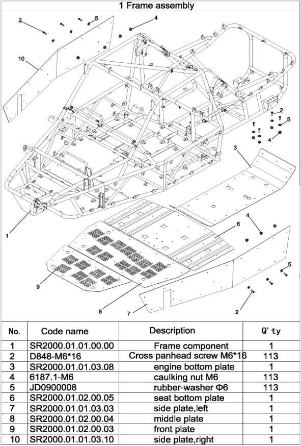
195 Frame 194
196 195
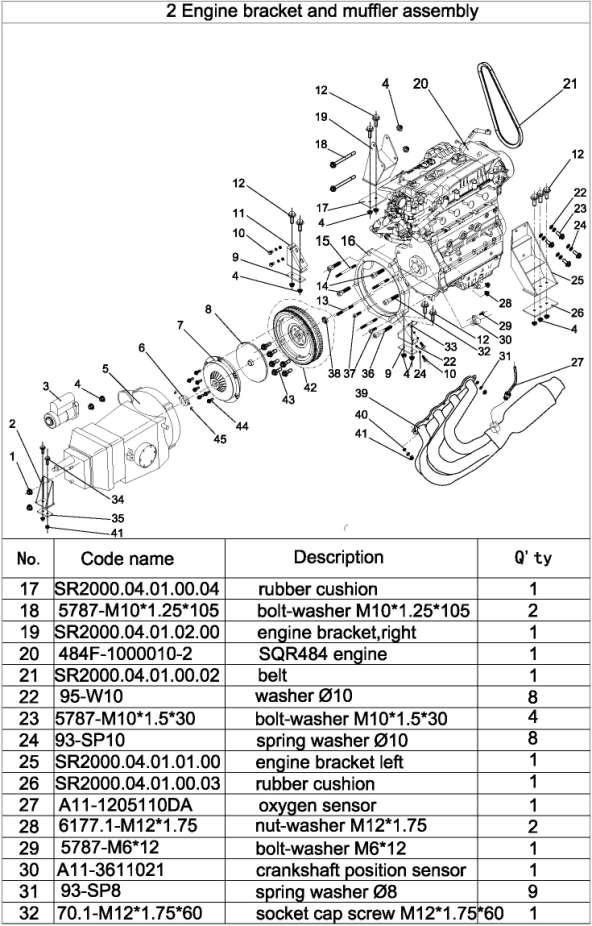
197 196
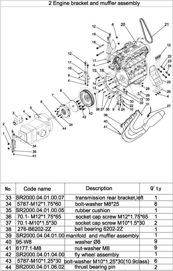
198 197
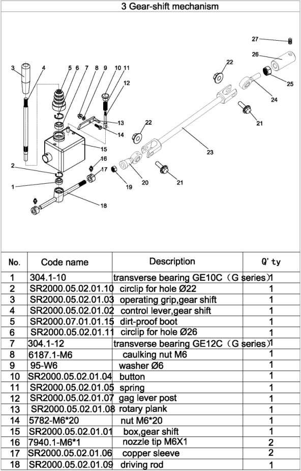
199 198
200 199
201 200
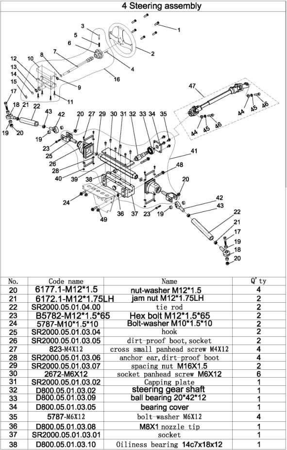
202 201
203 202
204 203
205 204
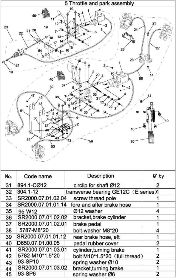
206 205
207 206
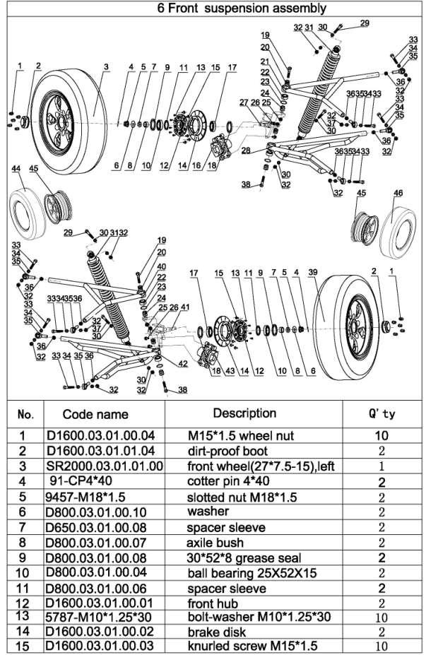
208 207
209 208
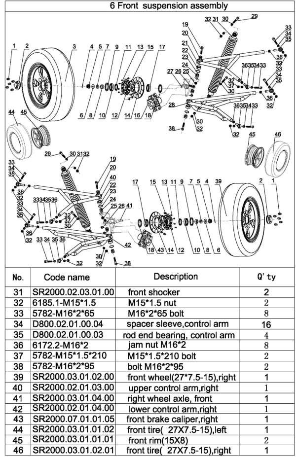
210 209
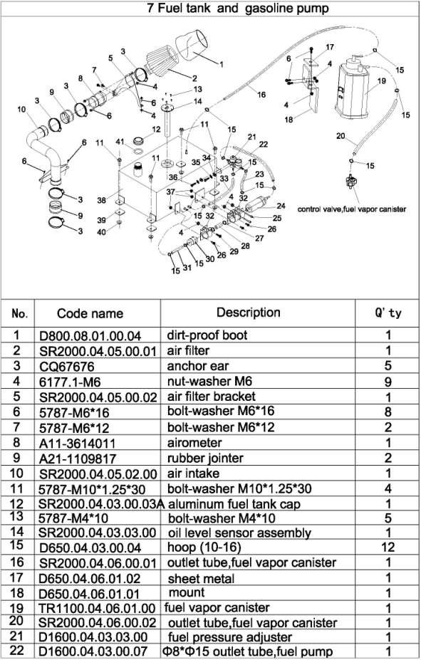
211 210
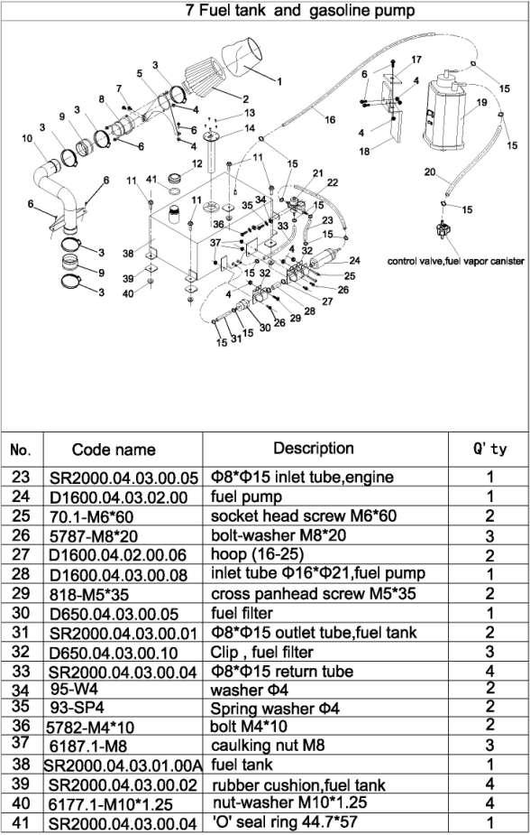
212 211
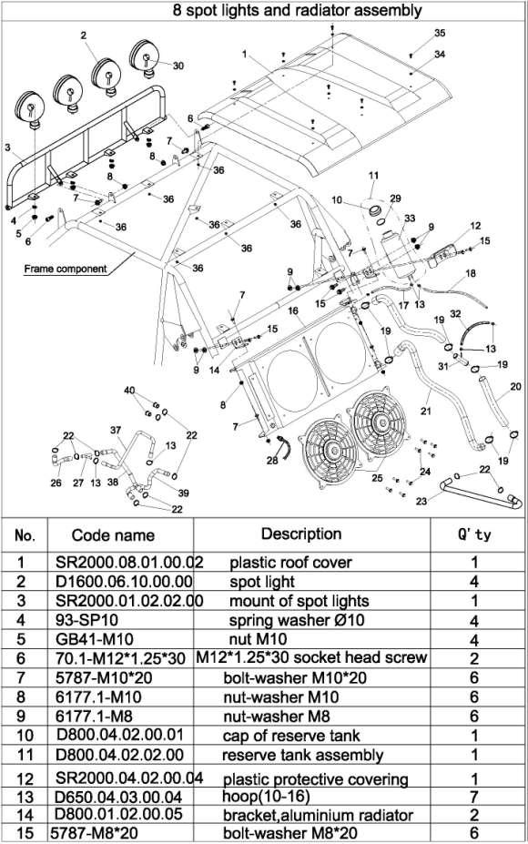
213 212
214 213
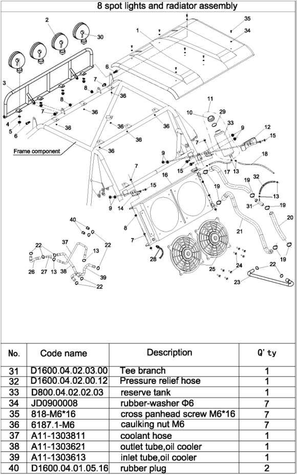
215 214
216 215
217 216
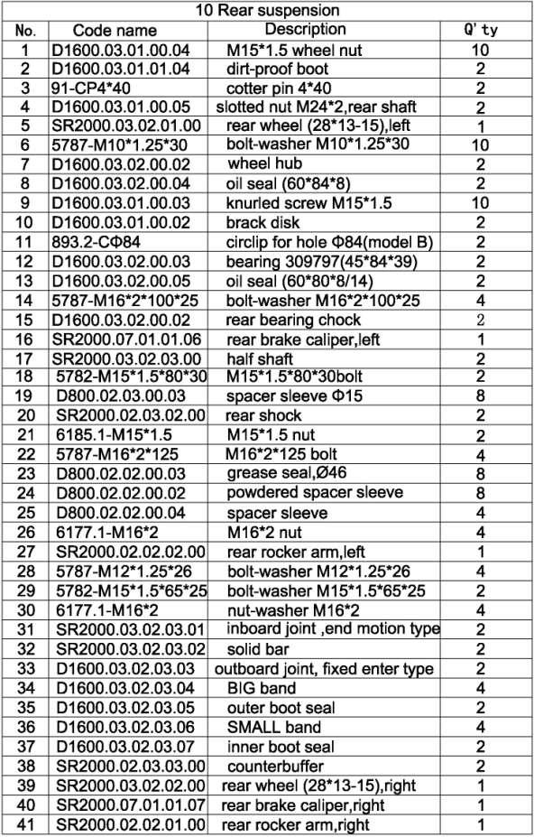
218 217
219 218
220 219
221 220
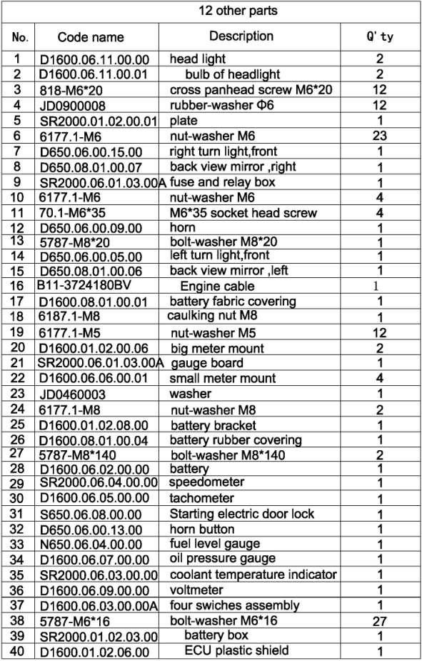
222 221
223 222

224 DEALER PRE-DELIVERY INSPECTION 223
Follow the Age Recommendation Adult Supervision should be present for all people under the age of 18.
 Your Kart will provide you with many years of service and pleasure. Providing you take responsibility for your own safety and understand the challenges you can meet while driving. There is much that you
Owner s manual. 150CC Go-Kart FOR OFF-ROAD USE ONLY READ THIS MANUAL CAREFULLY IT CONTAINS IMPORTANT SAFETY INFORMATION.
 Owner s manual READ THIS MANUAL CAREFULLY IT CONTAINS IMPORTANT SAFETY INFORMATION. MINIMUM RECOMMENDED OPERATOR AGE 14 150CC Go-Kart FOR OFF-ROAD USE ONLY OWNER S MANUAL FOREWORD 1 A FEW WORDS ABOUT SAFETY
DAZON Limited Warranty
 1 DAZON Limited Warranty The warranty policy applies to those cases where the new seller vehicle unloaded from its shipping container, set up and delivered by authorize dealer and under normal use and
JNSZ800DL. Owner s manual. Parts manual MINIMUM RECOMMENDED OPERATOR AGE FOR OFF-ROAD USE ONLY
 Owner s manual Parts manual JNSZ800DL READ THIS MANUAL CAREFULLY IT CONTAINS IMPORTANT SAFETY INFORMATION. MINIMUM RECOMMENDED OPERATOR AGE FOR OFF-ROAD USE ONLY This vehicle is designed and manufactured
DLX 400IIR Limited Warranty
 DLX 400IIR Limited Warranty The warranty policy applies to those cases where the new vehicle unloaded from its shipping container, set up and delivered by an authorized dealer, and under normal use and
DLX 400IIR Limited Warranty
 DLX 400IIR Limited Warranty The warranty policy applies to those cases where the new vehicle unloaded from its shipping container, set up and delivered by an authorized dealer, and under normal use and
MOTOX 70cc Assembly Manual
 MOTOX 70cc Assembly Manual Assembly Manual This manual should be considered a permanent part of the motorcycle and should remain if it is resold. This manual contains the latest product information available
CONTENT. 3. Maintenance
 CONTENT Foreword -------------------------------------------------------------------------------------------- 1 1. The performance, technical parameters and structure of Go Kart--------------------------------------------2
JNSZ250DN. Owner s Manual. Parts Manual MINIMUM RECOMMENDED OPERATOR AGE:
 Owner s Manual Parts Manual JNSZ250DN READ THIS MANUAL CAREFULLY IT CONTAINS IMPORTANT SAFETY INFORMATION. MINIMUM RECOMMENDED OPERATOR AGE: 16 FOR OFF-ROAD USE ONLY This vehicle is designed and manufactured
OWNER S MANUAL CONTENTS. Page 1. FORWORD 5 2. A FEW WORDS ABOUT SAFETY IMPORTANT SAFETY INFORMATION SAFETY LABELS...7
 CONTENTS OWNER S MANUAL Page 1. FORWORD 5 2. A FEW WORDS ABOUT SAFETY. 5 3. IMPORTANT SAFETY INFORMATION..6 4. SAFETY LABELS...7 5. QUALIFICATIONS FOR FUN-KART USERS 7 6. ARE YOU READY TO DRIVE?.9 7. IS
THIS VEHICLE IS FOR OFF-ROAD USE ONLY THIS VEHICLE IS NOT DESIGNED FOR USE ON RENTAL TRACKS OR RACING
 Book 1 of 2 Model 3171 Ages 13 and up 25 mph max speed Model 5210 Ages 13 and up 25 mph max speed Model 6152 Ages 13 and up 39 mph max speed Model 7151 Ages 13 and up 39 mph max speed FUN KART OPERATOR
NOTES FOR SAFETY OPERATOR-ONLY.
 NOTES FOR SAFETY Both the parents and their child must fully understand everything in this manual before riding. This vehicle is for OPERATOR-ONLY. This vehicle is only designed for operation on level,
This manual should be considered a permanent part of the ATV and should remain with the ATV when it is resold.
 This manual should be considered a permanent part of the ATV and should remain with the ATV when it is resold. This publication includes the latest production information available before printing. Honda
ATV-320 R OWNER S MANUAL
 ATV-320 R OWNER S MANUAL FOREWORD May we, the manufacturer, take this opportunity to thank you for choosing our ATV to serve you. This Owner s Manual is prepared for you to properly operate in safety.
WARNING - BEFORE YOU DRIVE
 See back cover for a pre-ride checklist section 3 operation WARNING - BEFORE YOU DRIVE 1. Always perform a pre-ride inspection of the vehicle using the checklist provided on the back cover of this manual.
OWNERS MANUAL. Two Stroke Dirt Bike. Distributed by SSR Motorsports. Address: Alondra Blvd, Norwalk CA
 OWNERS MANUAL Two Stroke Dirt Bike Distributed by SSR Motorsports Address: 12825 Alondra Blvd, Norwalk CA 90650 www.ssrmotorsports.com Please note that this is a general manual. The model of the vehicle
ATV-50/90/100 I/II/V OWNER S MANUAL
 1 ATV-50/90/100 I/II/V OWNER S MANUAL FOREWORD May we, the manufacturer, take this opportunity to thank you for choosing our ATV to serve you. This Owner s Manual is prepared for you the details as to
This manual should be considered a permanent part of the ATV and should remain with the ATV when it is resold.
 This manual should be considered a permanent part of the ATV and should remain with the ATV when it is resold. This publication includes the latest production information available before printing. Honda
Trench Filler for Compact Utility Loaders
 Form No. 3353-608 Rev A Trench Filler for Compact Utility Loaders Model No. 22472 260000001 and Up Operator s Manual Register your product at www.toro.com Original Instructions (EN) Contents Page Introduction................................
ATV-320 S/U ATV-320SD S/U OWNER S MANUAL V
 ATV-320 S/U ATV-320SD S/U OWNER S MANUAL V1.0 2014.03.01 0 FOREWORD May we, the manufacturer, take this opportunity to thank you for choosing our ATV to serve you. This Owner s Manual is prepared for you
SPECIFICATIONS TEST AND ADJUSTMENT SPECIFICATIONS SPECIFICATIONS ENGINE FD620D, K SERIES
 ENGINE FD620D, K SERIES SPECIFICATIONS SPECIFICATIONS TEST AND ADJUSTMENT SPECIFICATIONS Engine Oil Pressure Sensor Activates............................... 98 kpa (14.2 psi) Oil Pressure While Cranking
May we, the manufacturer, take this opportunity to thank you for choosing our ATV to serve you.
 FOREWORD May we, the manufacturer, take this opportunity to thank you for choosing our ATV to serve you. This Owner s Manual is prepared for you the details as to operate and maintenance necessarily to
3. INSPECTION/ADJUSTMENT
 3 3 INSPECTION/ADJUSTMENT SERVICE INFORMATION -------------------------------------------- 3-1 MAINTENANCE SCHEDULE ---------------------------------------- 3-2 FUEL LINE/FUEL FILTER -------------------------------------------
INSPECTION/ADJUSTMENT
 3 3 INSPECTION/ADJUSTMENT SERVICE INFORMATION----------------------------------------------------------------------- 3-1 MAINTENANCE SCHEDULE-------------------------------------------------------------------
3. INSPECTION/ADJUSTMENT
 3 SERVICE INFORMATION...3-0 FINAL REDUCTION GEAR OIL...3-7 MAINTENANCE SCHEDULE...3-2 DRIVE BELT...3-7 FUEL FILTER...3-3 BRAKE SHOE...3-8 THROTTLE OPERATION...3-3 BRAKE ADJUSTING NUT...3-8 AIR CLEANER...3-4
Honda TRX420TM/FM FOURTRAX 420/4 4 OWNER S MANUAL
 Honda TRX420TM/FM FOURTRAX 420/4 4 OWNER S MANUAL Introduction Congratulations on choosing your Honda ATV. When you own a Honda, you re part of a worldwide family of satisfied customers people who appreciate
1.CONTENTS 1. Contents Control location Before riding Safe riding Driving Use genuine spare parts Use
 1.CONTENTS 1. Contents... 1 2. Control location... 3 3. Before riding... 4 4. Safe riding... 4 5. Driving... 5 6. Use genuine spare parts... 5 7. Use of each component... 6 Gauges... 6 Operation of ignition
Light condition and operation Windshield glass condition Wiper blade condition Paint condition and corrosion Fluid leaks Door and hood lock condition
 GENERAL CHECKS Engine Compartment The following should be checked regularly: Engine oil level and condition Transmission fluid level and condition Brake fluid level Clutch fluid level Engine coolant level
Owner s Manual SZ250DS. Parts Manual MINIMUM RECOMMENDED OPERATOR AGE:
 Owner s Manual Parts Manual READ THIS MANUAL CAREFULLY IT CONTAINS IMPORTANT SAFETY INFORMATION. SZ250DS MINIMUM RECOMMENDED OPERATOR AGE: 16 FOR OFF-ROAD USE ONLY This vehicle is designed and manufactured
SPECIFICATIONS TEST AND ADJUSTMENT SPECIFICATIONS SPECIFICATIONS ENGINE FD620D, K SERIES
 TEST AND ADJUSTMENT Engine Oil Pressure Sensor Activates............................... 98 kpa (14.2 psi) Oil Pressure While Cranking (Minimum).......................... 28 kpa (4 psi) Oil Pressure.....................................
Operation Manual. 21 Inch Self-Propelled Lawn Mower MODEL #
 21 Inch Self-Propelled Lawn Mower MODEL # 106461 Operation Manual This safety alert symbol identifies important safety messages in this manual. Failure to follow this important safety information may result
SECTION 8 2 DO IT YOURSELF MAINTENANCE. Chassis
 DO IT YOURSELF MAINTENANCE Chassis SECTION 8 2 Checking the coolant level of the traction motor................ 184 Checking the radiator....................................... 185 Checking brake fluid........................................
Owner s manual JNSZ650UV
 Owner s manual JNSZ650UV INTRODUCTION Thank you for choosing JOYNER JNSZ650UV. It represents the result of many years of JOYNER experience in the production of utility vehicles. With the purchase of this
Wheel Horse. 44 Snowthrower. for 5xi Lawn and Garden Tractors. Model No & Up. Operator s Manual
 FORM NO. 8 Rev A Wheel Horse Snowthrower for 5xi Lawn and Garden Tractors Model No. 7966 890050 & Up Operator s Manual IMPORTANT: Read this manual, and your tractor manual, carefully. They contain information
SERIES OFF-ROAD KART USER S MANUAL. Thank you very much for your choice of this Off-road Kart.
 SERIES OFF-ROAD KART USER S MANUAL Dear Sir or Madam, Thank you very much for your choice of this Off-road Kart. This Off-road Kart is manufactured according to the full survey of market demand. We hope
AIR-COOLED DIESEL GENERATOR OWNERʼS MANUAL. This manual contains important safety information. TDG2500E TDGW7000E TDG7000SE TDG4500E
 AIR-COOLED DIESEL GENERATOR OWNERʼS MANUAL This manual contains important safety information. TDG2500E TDGW7000E TDG7000SE TDG4500E TDG8000-3 TDG7000SE-3 TDG7000E TDG8000E TDGW7000SE TDG7000E3 TDGW8000E
BLAZER250 OWNER S MANUAL BOOK FORWARD. Sincerely appreciate your choice of our vehicle, we will provide you the best services.
 BLAZER250 OWNER S MANUAL BOOK FORWARD Sincerely appreciate your choice of our vehicle, we will provide you the best services. This Owner s manual contains important safety and maintenance information.
ATV Safety... Important safety information you should know, plus a look at the safety related labels on your ATV.
 Contents These pages give an overview of the contents of your owner s manual. The first page of each section lists the topics covered in that section. ATV Safety... Important safety information you should
SECTION 6 3 SERVICE PROCEDURES AND SPECIFICATIONS. Chassis
 SERVICE PROCEDURES AND SPECIFICATIONS Chassis SECTION 6 3 Specifications........................................... 208 Checking brake fluid...................................... 210 Checking power steering
This manual should be considered a permanent part of the ATV and should remain with the ATV when it is resold.
 This manual should be considered a permanent part of the ATV and should remain with the ATV when it is resold. This Owner s Manual covers the TRX500FM and TRX500FPM models. You may find descriptions of
3. INSPECTION/ADJUSTMENT
 SERVICE INFORMATION...3-0 FINAL REDUCTION GEAR OIL...3-7 MAINTENANCE SCHEDULE...3-2 DRIVE BELT...3-7 FUEL FILTER...3-3 BRAKE SHOE...3-8 THROTTLE OPERATION...3-3 BRAKE ADJUSTING NUT...3-8 AIR CLEANER...3-4
SECTION 6 3 SERVICE PROCEDURES AND SPECIFICATIONS. Chassis
 SECTION 6 3 SERVICE PROCEDURES AND SPECIFICATIONS Chassis Specifications 206 Checking brake fluid 208 Checking power steering fluid 209 Checking tire pressure 210 Rotating tires 211 Checking and replacing
This manual should be considered a permanent part of the ATV and should remain with the ATV when it is resold.
 This manual should be considered a permanent part of the ATV and should remain with the ATV when it is resold. This Owner s Manual covers the TRX420FA and TRX420FPA models. You may find descriptions of
610 BUSHEL MANURE SPREADER
 610 BUSHEL MANURE SPREADER RODA MANUFACTURING 1008 LOCUST ST. HULL, IA. 51239 Art s-way Manufacturing 712-439-2366 Co., Inc. Hwy 9 West - PO Box 288 WWW.RODAMFG.COM Armstrong, IA. 50514 U.S.A 2 INTRODUCTION
Disassembly and Assembly
 SENR9973-01 September 2007 Disassembly and Assembly 400C Industrial Engine HB (Engine) HD (Engine) HH (Engine) HL (Engine) HM (Engine) HN (Engine) HP (Engine) HR (Engine) Important Safety Information Most
User Manual of Bagibike Electric Bicycles
 User Manual of Bagibike Electric Bicycles Model: Bagibike B16. http://www.bagibike.com Page 1 FOREWORD The following operation manual is a guide to assist you. This manual is not a complete document on
Operating and Assembly Manual
 Model 1080 Operating and Assembly Manual Midwest Equipment Manufacturing, Inc. 5225 Serum Plant Road Thorntown, IN 46071 08-02-16 SAFETY RULES Remember, any power equipment can cause injury if operated
K EN R A ugu st Specifications Industrial Engine. M G D (Engine) MGB (Engine)
 MGB (Engine)") K EN R 623 0-00 A ugu st 200 6 Specifications 2506-15 Industrial Engine M G A (Engine) MGB (Engine) M G D (Engine) Important Safety Information i01658146 Most accidents that involve product operation,
K EN R 623 0-00 A ugu st 200 6 Specifications 2506-15 Industrial Engine M G A (Engine) MGB (Engine) M G D (Engine) Important Safety Information i01658146 Most accidents that involve product operation,
Visit us at
 Item no.: 609268 Ages 3-8 ADULT SUPERVISION REQUIRED ADULT BATTERY INSTALLATION AND ASSEMBLY REQUIRED Please keep this manual as it contains important information. 0908-1-E/INT TM & The Little Tikes Company,
I: INSPECT AND CLEAN, ADJUST, LUBRICATE OR REPLACE IF NECESSARY C: CLEAN A: ADJUST R: REPLACE L: LUBRICATE I: INSPECTION D: DIAGNOSE
 2. Periodic Maintenance > Periodic Maintenance Chart XCITING 400i Maintenance Schedule Perform the pre-ride inspection (Owner's Manual) at each scheduled maintenance period. This interval should be judged
QUICK REFERENCE GUIDE
 QUICK REFERENCE GUIDE www.familygokarts.com CUSTOMER SERVICE Customer Service is our top prority and checking these simple steps will help us in better serving you needs. Please remember that although
Engine oil. Introduction. Warning and indicator lights WARNING
 Engine oil Introduction In this section you ll find information about: Warning and indicator lights Engine oil specifications Engine oil capacities Checking the engine oil level and adding oil Engine oil
Part 7 DO IT YOURSELF MAINTENANCE
 Part 7 DO IT YOURSELF MAINTENANCE Chapter 7 2 Engine and Chassis Checking the engine oil level Checking the engine coolant level Checking brake fluid Checking power steering fluid Checking tire pressure
COMPONENT LOCATIONS B C D G F C D F G
 E ABCDEF 0000 COMPONENT LOCATIONS O H B C D G F J M L K P I O N B A C D J H A E I F G N M FIG. CYLINDER HEAD ASSY. 0 0 0 PARTS MANUAL CYLINDER HEAD ASSY. M0-00-0 HEAD CYLINDER SUBASSY 0--00 PLUG SPARK(CHSA
Table of Contents. Safety symbols... 3 Assembly 6. Operation Maintenance Troubleshooting 11. Storage. 12. Notes. 13
 Table of Contents Safety symbols... 3 Assembly 6 Operation... 8 Maintenance... 10 Troubleshooting 11 Storage. 12 Notes. 13 2 Safety Information Attention; this machine can be dangerous! All operators should
SECTION 7 2 DO IT YOURSELF MAINTENANCE MR2 U. Engine and Chassis
 SECTION 7 2 DO IT YOURSELF MAINTENANCE Engine and Chassis Checking the engine oil level................................. 168 Checking the engine coolant level............................ 169 Checking brake
ENGINE TUNE-UP INSPECTION OF ENGINE COOLANT INSPECTION OF ENGINE OIL INSPECTION OF BATTERY. INSPECTION OF AIR FILTER (Paper Filter Type)
") ENGINE MECHANICAL - Engine Tune-Up EM-17 ENGINE TUNE-UP INSPECTION OF ENGINE COOLANT (See steps 1 and 2 on page CO-4) INSPECTION OF ENGINE OIL (See steps 1 and 2 on page LU-5) INSPECTION OF BATTERY (See
ENGINE MECHANICAL - Engine Tune-Up EM-17 ENGINE TUNE-UP INSPECTION OF ENGINE COOLANT (See steps 1 and 2 on page CO-4) INSPECTION OF ENGINE OIL (See steps 1 and 2 on page LU-5) INSPECTION OF BATTERY (See
Operating and Assembly Manual
 Model 470-/H/PRO/IC Operating and Assembly Manual Midwest Equipment Manufacturing, Inc. 5225 Serum Plant Road Thorntown, IN 46071 11-11-11 SAFETY RULES Remember, any power equipment can cause injury if
AMERICAN SPORTWORKS LIMITED WARRANTY
 MY VEHICLE IDENTIFICATION NUMBER Record the VIN number and Model number of your ASW Fun Kart below for service and insurance records. The VIN number can be found on the crossbar, behind the seat. VIN:
A-Type, S-Type, & Cruiser Scooters. Read and understand this entire manual before allowing child to use this product!
 A-Type, S-Type, & Cruiser Scooters OWNER S MANUAL Read and understand this entire manual before allowing child to use this product! NOTE: Manual illustrations are for demonstration purposes only. Illustrations
Water pump Owner's Manual
 Water pump Owner's Manual Safety Precautions I. General Safeguards Please read this operation manual to have a thorough understanding of the content there before use the product. Failure to do so may lead
SECTION 6 2 SERVICE PROCEDURES AND SPECIFICATIONS. Engine. Specifications
 SERVICE PROCEDURES AND SPECIFICATIONS Engine SECTION 6 2 Specifications........................................... 170 Fuel.................................................... 172 Facts about engine oil
Owner s Manual Parts manual TROOPER READ THIS MANUAL CAREFULLY IT CONTAINS IMPORTANT SAFETY INFORMATION. MINIMUM RECOMMENDED OPERATOR AGE:
 Owner s Manual Parts manual TROOPER T2,T4 READ THIS MANUAL CAREFULLY IT CONTAINS IMPORTANT SAFETY INFORMATION. MINIMUM RECOMMENDED OPERATOR AGE: 16 FOR OFF-ROAD USE ONLY This vehicle is designed and manufactured
SECTION 6 2 SERVICE PROCEDURES AND SPECIFICATIONS. Engine. Specifications
 SERVICE PROCEDURES AND SPECIFICATIONS Engine SECTION 6 2 Specifications........................................... 162 Fuel.................................................... 164 Facts about engine oil
1991 Volkswagen Vanagon Syncro
 corner of radiator. See Fig. 1. Fig. 1: Bleeding Cooling System 2. Open bleeder valve in engine compartment (turn counterclockwise). See Fig. 1. Fill expansion tank until full. Start and run engine at
North Dakota State University Grounds Maintenance Equipment
 North Dakota State University Grounds Maintenance Equipment I. Introduction Grounds maintenance equipment is an important part of the work activities on NDSU campus. They can make grounds maintenance jobs
WEBER CARBURETOR TROUBLESHOOTING GUIDE
 This guide is to help pinpoint problems by diagnosing engine symptoms associated with specific vehicle operating conditions. The chart will guide you step by step to help correct these problems. For successful
BT49QT-9O3 User s Manual
 BT49QT-9O3 User s Manual Preface Thank you very much for purchasing BAOTIAN brand motorcycle of model BT49QT-9O3, which developed by BAOTIAN MOTORCYCLE INDUSTRIAL CO., LTD. And welcome to join the driver
RASER R1/ RASER FX OWNER'S MANUAL
 RASER R1/ RASER FX OWNER'S MANUAL IMPORTANT NOTES FOR SAFE OPERATION FAILURE TO FOLLOW THE INSTRUCTIONS CONTAINED HEREIN MAY RESULT IN DAMAGE TO YOUR SCOOTER, DECREASE ENGINE LIFE, CAUSE INJURY TO YOURSELF
3. INSPECTION/ADJUSTMENT
 3 3 INSPECTION/ADJUSTMENT SERVICE INFORMATION-------------------------------------------------- 3-1 MAINTENANCE SCHEDULE---------------------------------------------- 3-3 FUEL LINE---------------------------------------------------------------------
Read and understand this entire manual before allowing child to use this product!
 FLASHRIDER 360 OWNER S MANUAL Read and understand this entire manual before allowing child to use this product! NOTE: Manual illustrations are for demonstration purposes only. Illustrations may not reflect
Read this manual carefully. It contains important safety information. Children under the age of 16 should be supervised by a responsible adult.
 WD90 Read this manual carefully. It contains important safety information. Children under the age of 16 should be supervised by a responsible adult. OWNER S MANUAL Minimum Age Requirement: 10 Model: 90cc
WARNING. The engine exhaust from this product contains chemicals known to cause cancer, birth defects or other reproductive harm.
 WARNING The engine exhaust from this product contains chemicals known to cause cancer, birth defects or other reproductive harm. We ve created a web site just for YOU! S S S S S S Check it out... Technical
MODELS 1324 & 1624 & 1824
 THE MODELS 1324 & 1624 & 1824 HYDRAULIC TRENCHERS CONGRATULATIONS! You are now the proud owner of a BARRETO trencher. Please take a moment of your time to look over the following information. Familiarize
USER MANUAL. GASOLINE SCOOTER (4 Stroke engine) OFF ROAD USE ONLY. Read these instruction carefully before using
 OFF ROAD USE ONLY. Read these instruction carefully before using") USER MANUAL GASOLINE SCOOTER (4 Stroke engine) OFF ROAD USE ONLY Read these instruction carefully before using Ⅰ.Safe for use(caution) 1. Don t allow anyone who dose not understand this instruction manual
USER MANUAL GASOLINE SCOOTER (4 Stroke engine) OFF ROAD USE ONLY Read these instruction carefully before using Ⅰ.Safe for use(caution) 1. Don t allow anyone who dose not understand this instruction manual
DO NOT RETURN TO STORE. NOTE:
 Pro Series Scooters Owner s Manual Read and understand this entire manual before allowing child to use this product! For assistance contact Razor. DO NOT RETURN TO STORE. NOTE: Illustrations are for demonstration
CHASSIS CONTENTS EXTERIOR PARTS 6-1 FRAME COVER 6-2 REAR FRAME COVER 6-4 FRONT WHEEL 6-6 FRONT BRAKE 6-10 HANDLEBARS 6-17 FRONT FORK 6-19
 CHASSIS CONTENTS EXTERIOR PARTS 6- FRAME COVER 6- REAR FRAME COVER 6-4 FRONT WHEEL 6-6 FRONT BRAKE 6-0 HANDLEBARS 6-7 FRONT FORK 6-9 STEERING 6-6 REAR WHEEL 6-3 REAR BRAKE 6-39 6 REAR SHOCK ABSORBER 6-43
CHASSIS CONTENTS EXTERIOR PARTS 7-1 FRONT WHEEL 7-2 FRONT BRAKE 7-6 HANDLEBARS 7-13 FRONT FORK 7-15 STEERING 7-23 REAR WHEEL 7-26 REAR BRAKE 7-30
 CHASSIS CONTENTS EXTERIOR PARTS 7- FRONT WHEEL 7-2 FRONT BRAKE 7-6 HANDLEBARS 7-3 FRONT FORK 7-5 STEERING 7-23 REAR WHEEL 7-26 REAR BRAKE 7-30 REAR SHOCK ABSORBER 7-32 SWING ARM 7-33 7 7- CHASSIS EXTERIOR
Disc Brake System ( For Cross-Country)
") Technical Service Instructions General Safety Information Disc Brake System ( For Cross-Country) SI-8C60F t WARNING Please use extra caution to keep your fingers away from the rotating disc brake rotor
Technical Service Instructions General Safety Information Disc Brake System ( For Cross-Country) SI-8C60F t WARNING Please use extra caution to keep your fingers away from the rotating disc brake rotor
RedGum GP160 Splitter. Owner s Manual
 RedGum GP160 Splitter Owner s Manual Product Description & Intended Purpose: This Log Splitter / Wood Splitter is an outdoor product that splits wood logs for use as fuel in a fireplace or a woodstove.
USER AND SAFETY MANUAL
 USER AND SAFETY MANUAL HANDLE- BARS STEM COLLAR ROD SADDLE SAFETY HOOK- STRIP BRAKE SUPPORT BARS AFT TUBE FRONT TUBE SAFETY RULES SECURE THE ROD AND ATTACH SAFETY HOOK-STRIP before every ride. RIDE WHEELA
MUDD-OX INC. MAX AND BUFFALO ATV OPERATOR S MANUAL MODEL YEARS DO NOT REMOVE THIS OPERATOR S MANUAL FROM THIS VEHICLE
 MUDD-OX INC. MAX AND BUFFALO ATV OPERATOR S MANUAL MODEL YEARS 1990-2015 DO NOT REMOVE THIS OPERATOR S MANUAL FROM THIS VEHICLE For parts and accessories visit www.max6x6.com 1 Your ATV can be hazardous
MANUAL FLUID EXTRACTOR
 Please read and save these instructions. Read through this owner s manual carefully before using product. Protect yourself and others by observing all safety information, warnings, and cautions. Failure
1.6L 4-CYL - VIN [E]
![1.6L 4-CYL - VIN [E]](/thumbs/81/84172348.jpg "1.6L 4-CYL - VIN [E]") 1.6L 4-CYL - VIN [E] 1993 Nissan Sentra 1993 NISSAN ENGINES 1.6L 4-Cylinder NX, Sentra * PLEASE READ THIS FIRST * NOTE: For engine repair procedures not covered in this article, see ENGINE OVERHAUL PROCEDURES
1.6L 4-CYL - VIN [E] 1993 Nissan Sentra 1993 NISSAN ENGINES 1.6L 4-Cylinder NX, Sentra * PLEASE READ THIS FIRST * NOTE: For engine repair procedures not covered in this article, see ENGINE OVERHAUL PROCEDURES
NOT RETURN TO STORE. NOTE:
 A 5 Lux Scooter Owner s Manual Read and understand this entire manual before allowing child to use this product! For assistance contact Razor. DO NOT RETURN TO STORE. NOTE: Manual illustrations are for
BRAKE SYSTEM Return To Main Table of Contents
 BRAKE SYSTEM Return To Main Table of Contents GENERAL... 2 BRAKE PEDAL... 10 MASTER CYLINDER... 13 BRAKE BOOSTER... 16 BRAKE LINE... 18 PROPORTIONING VALVE... 19 FRONT DISC BRAKE... 20 REAR DRUM BRAKE...
Model 452-DIC/DH. Operating and Assembly Manual
 . Model 452-DIC/DH Operating and Assembly Manual Palmor Products Inc. 5225 Serum Plant Road Thorntown, IN 46071 02-14-12 SAFETY RULES Remember, any power equipment can cause injury if operated improperly
Electric Car User Manual
 Electric Car User Manual The owner s manual contains important safety information as well as assembly, use and maintenance instructions. The Ride-on Car must be assembled by an adult who has read and understands
Typical Install Instructions
 Typical Install Instructions Read & understand all steps of these instructions before beginning this installation. WEBER Conversion Kit, VW T-1/2, up to 1835cc 32 / 36 DFEV Weber Carburetor These instructions
Operating and Assembly Manual
 Model 455-IC/PRO/H Operating and Assembly Manual Midwest Equipment Manufacturing, Inc. 5225 Serum Plant Road Thorntown, IN 46071 03-08-12 SAFETY RULES Remember, any power equipment can cause injury if
Instruction manual DENVER DBO
 Instruction manual DENVER DBO-6500 www.facebook.dk/denver-electronics Before operating this vehicle, read all the instructions for safe assembly and operations. User s manual can guide you through the
Walker Loader Bucket OPERATOR S AND PARTS MANUAL
 Walker Loader Bucket OPERATOR S AND PARTS MANUAL Please Read and Save These Instructions For Safety, Read all Safety and Operation Instructions Prior To Operating Machine P/N 6690 TABLE OF CONTENTS Introduction
COLT 2310, 2510, AND 2712 COM PACT TRACTORS CHAPTER 9 TROUBLESHOOTING AND ANALYSIS
 COLT 2310, 2510, AND 2712 COM PACT TRACTORS CHAPTER 9 TROUBLESHOOTING AND ANALYSIS 9-A-1 UPON RECEIVING ANENGINE FORRE- PAIR. Learn the history of the unit from the customer. While the customer is present
9-2 In case of emergency
 In case of emergency If you park your vehicle in case of an emergency... 9-2 Temporary spare tire... 9-2 Maintenance tools... 9-3 Flat tires... 9-5 Changing a flat tire... 9-5 Tire pressure monitoring
Disassembly and Assembly
 K EN R 623 2-00 August 2006 Disassembly and Assembly 2506-15 Industrial Engine M G A (Engine) MGB (Engine) M G D (Engine) Important Safety Information Most accidents that involve product operation, maintenance
Model 858-RH. Operating and Assembly Manual. Palmor Products Inc Serum Plant Road Thorntown, IN 46071
 Model 5-RH Operating and Assembly Manual Palmor Products Inc. 55 Serum Plant Road Thorntown, IN 6071 3/31/015 SAFETY RULES Remember, any power equipment can cause injury if operated improperly or if the
YFM125GZ This A This ATV should not be ridden by anyone under 16 years of age.
 READ THIS MANUAL CAREFULLY! It contains important safety information. OWNER S MANUAL WARNING LIT--- YFMGZ This A This ATV should not be ridden by anyone under years of age. C-- EBU0 Read this manual carefully
HOW - TO EMISSION CONTROL BASICS EMISSION CONTROL BASICS
 HOW - TO EMISSION CONTROL BASICS EMISSION CONTROL BASICS Tool And Material Checklist Bore Brush Thermometer Portable Vacuum Pump Screwdriver Combination Wrench Set 3/8 Drive Socket Set Tachometer Rag Service
Installation Instructions
 Preparing your vehicle to install your brake system upgrade 1. Rack the vehicle. 2. If you don t have a rack, then you must take extra safety precautions. 3. Choose a firmly packed and level ground to
Operating and Assembly Manual
 Model 455-IC/PRO/H Operating and Assembly Manual Palmor Products Inc. 5225 Serum Plant Road Thorntown, IN 46071 03-08-12 SAFETY RULES Remember, any power equipment can cause injury if operated improperly