UNIK2E _ V2 (COMPLETE) UNIK2ESK _ V2 (WITHOUT BOX AND TRANSFORMER)
|
|
|
- Samuel Stevens
- 5 years ago
- Views:
Transcription
 BOX IP 54 TECHNICAL INSTALLATION MANUAL")


1 ELECTRONIC CONTROL UNIT FOR TWO 12VDC MOTOR UNIK2E _ V2 (COMPLETE) UNIK2ESK _ V2 (WITHOUT BOX AND TRANSFORMER) BOX IP 54 TECHNICAL INSTALLATION MANUAL FOR AUTOMATIC GATES WARNING! Before installing, thoroughly read this manual that is an integral part of this Kit. Prastel S.p.A. declines any responsibility in the event current standards in the country of installation are not complied with The symbol CE conforms with European Directive R&TTE 99/05/CE
2 1. INTRODUCTION MAIN FEATURES TECHNICAL SPECIFICATIONS CONNECTION AND SET UP OF THE CONTROL UNIT GENERAL DIAGRAM OF SETTINGS AND CONNECTIONS SIMPLIFIED LEARNING PROCEDURE (also see pages 8-10) PROFESSIONAL LEARNING PROCEDURE (see also pages 8-10) CONTROL UNIT OPERATING LOGIC (ANALYTIC EXAM) PROGRAMMING AND CANCELLATION OF THE REMOTE CONTROLS OPERATION OF THE SAFETY DEVICES MOTOR SPEED - TRIMMER FOR DELAY BETWEEN MOTORS - TRIMMER DEL OPENING AND CLOSING OPERATING MODE PEDESTRIAN OPENING FUNCTION OBSTACLE SENSITIVITY DETECTION - TRIMMER OBS FLASHING LIGHT GATE OPEN WARNING LIGHT SLOW-DOWN ELECTRIC LOCK COURTESY LIGHT BUFFER BATTERY SOLAR PANEL MANAGEMENT LOGICAL STOP (STP INPUT) CONTROL UNIT MEMORY FAULT SIGNALLING LED PROGRAMMING THROUGH GTSYSTEM ACCESSORIES ABSORPTION CHECK INFORMATION TROUBLESHOOTING SAFETY WARNINGS FOR INSTALLATION AND USE
3 1. INTRODUCTION The universal self-learning UNIK2E control unit has been designed for the automation of an access with 1 or 2 12VDC (24VDC)* motors with or without limit switches. Its innovative self-learning procedure makes for quick and easy installation and its three trimmers permit fine adjustment of all main parameters: force (or speed), pause time, obstacle detection sensitivity and closing delay between the two leaves of the gate when two motors are used. The following are available: - simplified programming, thanks to which the unit automatically performs a learning operation to acquire running time and determine slow-down setting at ninety percent of opening and closing runs; - A professional programming in which the installer can determine the instant in which the gate starts to slow-down, the enabling of the pedestrian opening via radio, the safety device trigger mode. 2. MAIN FEATURES Management and control of 12 VDC (or 24 VDC)* powered, 1 or 2 motor-driven automated accesses Motors closing offset adjustable from 0 to 15 seconds using trimmers Double limit switch input open close Motor force (speed) adjustable from %.using a trimmer. Customisable partial opening (for pedestrian transit) Softstart (slow motor start) 1 to 60 stand-by time adjustment via trimmer. 0.1 to 3.0 obstacle detection triggering time adjustment via trimmer. Initial settings using dip-switches Signalling LEDs (8) Expansion for electric lock 12V 15W max (optional board ELU) Expansion for courtesy light 230VAC 500W max (optional board LCU) Built in battery charger with solar panel management Box predisposed for optional 12V 1.2Ah battery for emergency manoeuvres (max connectable battery 7Ah) Built-in 433MHz rolling-code receiver with 180 memorisable codes Flash microprocessor re-programmable on-board via serial interface. Programming and control of the control unit using a portable terminal GTSYSTEM (optional) Built to European reference Directive Standards (R&TTE 99/05/CE) DECLARATION OF CONFORMITY Prastel S.p.A. declares that UNIK2E IS IN ACCORDANCE with the 99/05/EC (R&TTE) direcitve The complete declaration of conformity is available in Prastel or to the internet address 3. TECHNICAL SPECIFICATIONS Transformer power supply: 230VAC Control unit power: 12VAC (20VAC)* Motor output: 12 VDC max 2 x 50Watt (24VDC max 2 x 60W)* Max current peak of motor: 10 Amperes Accessories power: 12 VDC ma protected by fuse (see info page 13) Environmental operating temperature : -20 C / + 55 C Programming parameters: memorised in EEPROM BOX IP rating: IP54 (*)When using 24VDC motors, replace the supplied transformer with a 230/20VAC transformer with at least 20VA more power than the motor. The maximum power of the 24VDC motor driven by the control unit is 120W. Only 12V batteries can be connected to the control unit, so when there is no mains power 24VDC motors will be powered at 12VDC. 3
4 4. CONNECTION AND SET UP OF THE CONTROL UNIT a) Before installing the UNIK2E control unit, read the General safety warnings and notes (page 13). b) Fix the box using the special fixing holes. c) Mount a differential thermo-magnetic circuit breaker 6A (IC=30mA) on the mains supply as specified in the current reference standards (IC = differential current). d) Place the supplied cable-ways and insert the cables keeping the power and supply cables separate from each other. e) Connect the external accessories making sure that the total of the average absorption of all the connected accessories is less than the maximum current available (see info page 11). f) ATTENTION: Connect the limit switches if present; otherwise do not jump inputs FC1, FC2, FO1 and FO2 in the terminal board. g) ATTENTION: if there are no electrical limit switches and no mechanical stop in opening, proceed as follows to define the manoeuvre times during learning: Press pushbutton 1 of the remote control or pushbutton P1/SET to stop the gate in the desired position. Press pushbutton 2 of the remote control or pushbutton P2/SET to stop the gate in the desired position. h) Check the correct connection and operation of all the accessories connected to the terminal board. NOTES: INITIAL FACTORY SETTINGS If there is no programming, the control unit will operate as follows: Step-step mode with automatic closing disabled. No slow-down Closing safety present No opening safety Obstacle detection trigger time (OBS) 1 second 3 second opening and closing time of the motors Safety test disabled Kick-back disabled Pushbutton 1 of transmitters enabled Rapid re-closing disabled INITIAL SETTING OF THE TYPE OF OPERATOR Check that the control unit is set for the application requested. When switched on, the red RAD LED flashes for the number of times set in the control unit. To modify the setting proceed as follows: NUMBER OF FLASHES APPLICATIONS 1 Linear actuators 2 Operators with variable lever (Variable absorption) 1. press the P2/RAD pushbutton until the corresponding red RAD LED lights up 2. press the P1/SET pushbutton, the control unit switches to another application 3. press the P2/RAD pushbutton again to exit the programming 4. The red RAD LED switches off to confirm that programming has been exited. MOTOR POWER SUPPLY The control unit adapts itself to run with motors of 12 or 24VDC according to the voltage with which it is powered. The UNIK2E control unit is fitted with a toroidal transformer with a 12VAC secondary. 4


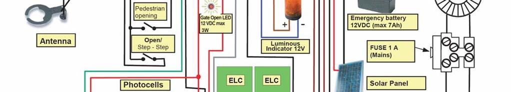
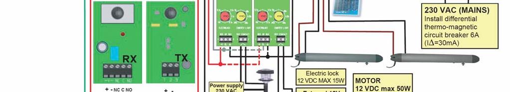

5 4.1 GENERAL DIAGRAM OF SETTINGS AND CONNECTIONS 5
6 4.2 SIMPLIFIED LEARNING PROCEDURE (also see pages 8-10) 1. Verify the initial settings. 2. Program the remote controls (if needed) with the gate stopped (green LED GC turned on) according to the following: a) Press the program button P2/RAD for two seconds: the red LED RAD lights up. b) Press the desired button on each transmitter. c) Press the program button P2/RAD to exit the programming mode. LEARNING START: RESET: 2 1 press and hold 3 Position the the programming gates half Yellow LED button P1/SET for open flashes 2 seconds Within 5 seconds, press the programming button P2/RADIO for 1 second 1 INITIAL SETTINGS OF THE CONTROL UNIT Yellow LED stays on 2 DIP N. Description DIP STATUS Operation 1, 2 CHRADIO 3 FAST 4 STRIKE 5 LAMP 6 STEP 7 AUTO 8 PHTEST Force/speed (FOR) OFF OFF Pause time (PAU) TRIMMERS Button 1 of the TX enabled OFF ON Button 2 of the TX enabled ON OFF Button 3 of the TX enabled ON ON Button 4 of the TX enabled OFF Rapid re-closing disabled ON OFF ON OFF ON OFF ON OFF ON OFF ON Rapid re-closing enabled Lock stroke disabled Lock stroke enabled Flashing light fixed Flashing light flashing OPEN/PAUSE/CLOSE Mode STEP by STEP mode Automatic closing disabled Automatic closing enabled Safety test disabled Gate open spy activated Safety test enabled Gate open spy deactivated Obstacle sensitivity (OBS) Leaves delay (DEL) 5 4 The two leaves briefly open If motors turns in reverse, invert wires and start procedure again from RESET. The second leaf closes ATTENTION If first leaf instead of second leaf closes, exchange the two motors and repeat the procedure from RESET 7 6 The first leaf closes The two leaves open until mechanical stop or electrical limit switches 8 Pause for 1 second 3 Reg. from 50 to 100% Reg. de 0 à 60s Obstacle intervention time from 0,1 to 3 sec. OPERATOR MODEL SETTING (pag. 4) Closing delay from 0 to 15 sec. 9 The two leaves close until mechanical stop or electrical limit switches. Yellow LED switches off Adjust trimmers if necessary ATTENTION A variation of trimmer FOR (speed) requires the repetition of the learning procedure from RESET (the manoeuvre time changes) End of learning procedure 6
7 4.3 PROFESSIONAL LEARNING PROCEDURE (see also pages 8-10) Using the professional learning procedure the installer can determine: a) the instant in which the opening and closing slow-down starts b) the pedestrian function c) the safety device trigger mode. When the motor and the safety devices are connected, programme the remote controls to be used (see page 8) with the gate stopped (green LED GC turned on). Position the gates half open RESET: press and hold the programming button P1/SET for 2 seconds Yellow LED flashes Within 5 seconds, press the programming button P2/RADIO for 1 second The second leaf then the first leaf close ATTENTION : if there are no electric limit switches or mechanical stop in opening see note 4, point g The two leaves briefly open If motor turns in reverse, invert wires and start procedure again from RESET. Yellow LED stays on MANUAL INTERVENTION TO CHANGE THE FUNCTIONS Safety intervention in opening The EDG safety in opening must: Stop then Press P1/SET or invert for 2 sec. remote control button 1 Stop then open when cleared Press P2/RAD or button 2 of the remote control The gate opens Opening slowdown YES When the slow-down is to start press button 1 of a remote control for leaf 1 and button 2 for leaf 2. NO End of opening Electric limit switch or mechanical stop triggering End of closing Electric limit switches or mechanical stop intervention Pedestrian function NO Closing slowdown YES When the slow-down is to start press button 1 of a remote control for leaf 1 and button 2 for leaf 2. Press P1/SET or remote control button 1. Press P2/RAD or button 2 of the remote control The gate closes Stop then invert Stop then invert when cleared Safety intervention in closing Photocell PHO in closing must: Will pedestrian function be used? NO Press together P1/SET and P2/RAD YES only by wire YES by radio + by wire Press the button of the remote control that will be used for the pedestrian function (different from 1) Press P1/SET or button 1 of the remote control Control unit starts pedestrian opening Press P1/SET or button 1 of the remote control to stop pedestrian opening Control unit carries out STOP and re-closing Yellow LED turns off. End of learning. Adjust trimmers if necessary. ATTENTION A variation of trimmer FOR (speed) requires the repetition of the learning procedure from RESET. 7
8 5. CONTROL UNIT OPERATING LOGIC (ANALYTIC EXAM) 5.1 PROGRAMMING AND CANCELLATION OF THE REMOTE CONTROLS With the receiver built into the control box, Prastel dip-switch, fixed code and rolling code remote controls can be indifferently learned Programming Power the control panel and with the automation stopped (green LED GC turned on): Press the P2/RAD pushbutton: the red LED lights up to indicate that the programming is activated. Make a transmission by pressing one of the pushbuttons on the transmitter The code is memorised. During code insertion, the red LED flashes slowly. At the end, the red LED returns to a fixed light to indicate that a new remote control can be inserted. Memorise all the transmitters by carrying out a transmission with a chosen channel. At the end of the operation press the P2/RAD pushbutton again to exit the procedure. The red LED switches off. ATTENTION: The exit from the procedure occurs automatically 10 seconds after the last transmission Total cancellation of the codes Press and hold down the P2/RAD pushbutton for 3 seconds; the red LED starts flashing quickly. Press the P2/RAD pushbutton again (within 6 seconds) to confirm the cancellation. The confirmation is signalled when the red LED starts flashing more rapidly Enabling new remote Rolling Code transmitters (RPA) To enable a new transmitter without intervening on the receiver, a transmitter already enabled for the authorisation must be used (MPSTP2E, MPSTL2E, MPSTL4E, MT2E, MT4E, TRQ2 or TRQ4). With this authorised transmitter, press and release the RPA learning pushbutton (also see the instructions of the TX used). Carry out this operation 5-6 metres from the receiver (the LED signals the activation). Transmit by pressing one of the channel pushbuttons of the new transmitter to be enabled. Enable all the new transmitters by pressing a pushbutton on each one of them. The exit from the procedure occurs automatically 10 seconds after the last transmission. Check the effective programming of the transmitters by carrying out an opening manoeuvre with each of them Choosing the transmitter pushbutton To select the radio channel that will activate the manoeuvre cycle set DIP 1 and 2 as follows: DIP- SWITCH 1 DIP- SWITCH 2 Pushbutton Active OFF OFF Pushbutton 1 OFF ON Pushbutton 2 ON OFF Pushbutton 3 ON ON Pushbutton OPERATION OF THE SAFETY DEVICES Photocell (PHO input) When triggered, the photocell provokes: - in closing phase, an inversion of the motion, either immediate or when cleared, according to the programming, - in opening phase it has no effect, - when the access is closed it has no effect on the opening commands if set for immediate inversion, otherwise it delays the opening until it is cleared, - if the access is open it inhibits the closing commands. The control unit has a function of rapid access closing after the triggering of the photocell (see paragraph 5.3.4) Safety in Opening (EDG/PED input) Safety devices can be connected (self-testing or not) to the EDG/PED input on the control unit (e.g. fixed wire ribs, pneumatically-operated ribs, etc.). The safety acts as follows: - in closing phase it has no effect - in opening phase it provokes an inversion of direction for 2 seconds, - when the gate is closed the opening commands are inhibited, 8
9 - when the gate is open the closing commands are inhibited, Using the professional learning, the EDG/PED input can be set as internal photocell: - in closing phase it provokes an inversion of direction when cleared, - in opening phase it provokes a STOP and opening continues when cleared, - when the gate is closed it delays opening until it is cleared, - when the access is open it inhibits the closing commands Safeties Self-test The control unit has a self-test function of the safeties connected to the PHO input of the control unit; it switches off the transmitter to check the commutation of the corresponding receiver contact before the execution of each manoeuvre. In this case, the gate open warning light is not available. To activate this self-test function proceed as follows: - switch DIP 8 PHTEST to ON - connect the positive of the photocell transmitter power to terminal 10 ( +TX ) With the Self-test function active the photocell transmitters are only powered when the manoeuvre is taking place, thus giving a major saving of energy. If the enabling of the safety self-test is not required - switch DIP 8 PHTEST to OFF - connect the positive of the photocell transmitter power to the terminal 9 ( +V ) 5.3 TRIMMER FOR - MOTOR SPEED Trimmer FOR adjusts the voltage applied to the motors during operations, which means adjusting the speed of the motors. With the trimmer turned fully counter-clockwise the speed of the motor if 50% of the maximum speed. With the trimmer at half travel the speed of the motor if 50% of the maximum speed. ATTENZION: Changing the setting of trimmer FOR requires repeating the learning procedure, since the travel times and the slow-down start times change. Speed 50% Speed 75% Speed 100% 5.4 TRIMMER DEL - DELAY BETWEEN MOTORS Trimmer DEL can be used to adjust the delay between the two motors in opening and closing operations. If the trimmer is turned fully counter-clockwise, the delay is 0 both in opening and in closing, and the two leaved will move together. In all the other positions of the trimmer, the delay in opening is 3 seconds and the delay in closing varies from 0 to 15 seconds according to the position of the knob. delay 0 in opening delay 0 in closing delay 3 seconds in opening delay 7 seconds in closing delay 3 seconds in opening delay 15 seconds in closing 5.5 TRIMMER PAU - OPENING AND CLOSING OPERATING MODE Time controlled automatic closing mode Switch the dip-switch 6 to OFF and the dip-switch 7 to ON. Set the PAU trimmer in an intermediate position according to the pause time desired. The pause time can be set between 3 and 60 seconds and is increased by rotating the trimmer clockwise. pause time about 1 sec. pause time about 30 sec. pause time about 60 sec. In this mode, if a command is received via radio or via the STR input, the control unit does the following: - drives the two motors without 2 nd motor delay if the DEL trimmer is turned fully counter-clockwise, with a 2 nd motor delay of 3 seconds for all the other positions of the DEL trimmer - drives the motors for one second at reduced speed (softstart) and then at the speed set on the FOR trimmer. 9
10 - opening stops when the limit switches or the obstacle detection system intervenes or when the manoeuvre time has elapsed. If other commands are given during opening they will have no effect. - with the automation stopped and in automatic pause each time the timer re-starts from zero. Once the pause time has elapsed, the closing manoeuvre takes place and the control unit: - carries out a 1 second fixed pre-flash - drives the two motors with a 2 nd motor delay as set on the DEL trimmer - drives the motors for one second at reduced speed (softstart) and then at the speed set on the FOR trimmer. - if another command is given during closing the control unit commands a complete re-opening. - closing stops when the limit switch or the obstacle detection system intervenes or when the manoeuvre time has elapsed. ATTENTION: Maintaining the opening contact ( STR terminal) closed, with a temporised relay for example, the control unit will command opening and the automation will remain open with automatic closing disabled until the contact is re-opened again (Company Function) Step by step mode without automatic closing Switch the dip-switch 6 to ON and the dip-switch 7 to OFF. The step by step command sequence is OPEN-STOP-CLOSE-STOP The opening and closing manoeuvres take place as described in the previous paragraph Step by step mode with automatic closing Switch the dip-switch 6 to ON and the dip-switch 7 to ON. The step-step logic is OPEN/STOP/CLOSE/STOP. When the opening manoeuvre has been completed and the pause time set on the PAU trimmer has elapsed the control unit effects automatic closing. If, when the automation is closed, a radio command is given, either through the STR input command or the START pushbutton on the board, the control unit: - commands a one second fixed pre-flash - drives the two motors without 2 nd motor delay if the DEL trimmer is turned fully counter-clockwise, with a 2 nd motor delay of 3 seconds for all the other positions of the DEL trimmer - drives the motors for one second at reduced speed (softstart) and then at the speed set on the FOR trimmer. - opening stops when the limit switch or the obstacle detection system intervene or when the manoeuvre time has elapsed or with a radio or manual command. In the latter case the control unit disables the automatic closing and another command must be given to re-start the manoeuvre. If the automation is completely open, once the pause time has elapsed the closing manoeuvre takes place. The control unit: - commands a 1 second fixed pre-flash - drives the two motors with a 2 nd motor delay as set on the DEL trimmer - drives the motors for one second at reduced speed (softstart) and then at the speed set on the FOR trimmer. - closing stops when the limit switch or the obstacle detection system intervenes or when the manoeuvre time has elapsed Automatic closing and rapid re-closing mode Switch the dip-switch 6 to OFF and the dip-switch 7 to ON. Switch the dip-switch 3 to ON. The control unit does the following: a) if the photocell is triggered during opening, the control unit continues the opening, and when the photocell is cleared effects a STOP followed, after one second, by the re-closure. b) if the photocell is triggered during standby with the gate open, when the photocell is cleared, after one second, automatic re-closure occurs. c) if the photocell is triggered during closure, the control unit effects an inversion and, when the photocell is cleared, it effects a STOP followed, after one second, by the re-closure. If during the opening cycle or during the pause the photocell is not triggered, the pause time is as set on the PAU trimmer OPEN-CLOSE-OPEN mode Switch the dip-switch 6 to OFF and the dip-switch 7 to OFF. If, when the automation is closed, a radio command is given, either through the STR input command or the START pushbutton on the board, the control unit: - commands a one second fixed pre-flash - drives the two motors without 2 nd motor delay if the DEL trimmer is turned fully counter-clockwise, with a 2 nd motor delay of 3 seconds for all the other positions of the DEL trimmer - drives the motors for one second at reduced speed (softstart) and then at the speed set on the FOR trimmer. - opening stops when the limit switch or the obstacle detection system intervenes or when the manoeuvre time has elapsed. If other commands are given during opening they will have no effect. When the automation is completely open, to start closing give a radio or manual command and the control unit: - commands a 1 second fixed pre-flash - drives the two motors with a 2 nd motor delay as set on the DEL trimmer 10
11 - drives the motors for one second at reduced speed (softstart) and then at the speed set on the FOR trimmer. - if a command is given during closing the control unit commands the complete re-opening - closing stops when the limit switch or the obstacle detection system intervenes or when the manoeuvre time has elapsed. 5.6 PEDESTRIAN OPENING FUNCTION The pedestrian function can be assigned with the professional learning to channel 2/3/4 of the remote control. With a PEDESTRIAN OPENING ( EDG/EDG terminal) command on the input, the control unit commands an opening for the first leaf for a time of: - 5 seconds if no learning has been carried out, - complete opening if a simplified learning has been carried out - that set by the installer if a professional learning has been carried out. Closing is triggered by a manual command, or automatically if the automatic closing function is enabled. The complete opening command has always priority over the pedestrian opening, therefore if, during a pedestrian manoeuvre a complete opening command is received, the control unit will command a complete opening of the automation. 5.7 TRIMMER OBS - OBSTACLE SENSITIVITY DETECTION The OBS TRIMMER is used to adjust at the same time the delay time of intervention after an obstacle has been detected and the threshold of the counter-force against the operator necessary to trigger the intervention. Both the counter-force and the delay time increase when the trimmer is turned clockwise. The delay time can be adjusted between 0.1 and 3 seconds. This function is useful to overcome any critical points of the operator which cause a higher power absorption by the motor for a short time. delay time about 0,1 sec. delay time about 1,5 sec. delay time about 3 sec. If electric limit switches are present, the obstacle detector will provoke an inversion of the motion in closing and a 2 second inversion in opening. If there are no electric limit switches the obstacle detector provokes: - in closing an inversion of the motion unless it is in the last five seconds of the manoeuvre, where does a STOP - in opening an inversion of the motion for 2 seconds unless it is in the last five seconds of the manoeuvre, where does a STOP. 5.8 FLASHING LIGHT The control unit has two output terminals (LAMP) to command a low voltage flashing light. The light start flashing 1 second before each opening manoeuvre and 1 second before each closing manoeuvre. If the dip-switch 5 is in the OFF position the power supply to the flashing light is continuous. Therefore the terminals must be connected to a low voltage flashing light with a built-in oscillating circuit (type FEBOLIX 12VDC 2W). If the dip-switch 5 is in the ON position the power supply is intermittent and therefore a normal lamp without oscillating circuit can be connected (12VDC, Max 10W). During the closing manoeuvre, the flashing frequency is twice as fast as that during opening. The flashing light is only activated during movement. If AC mains power supply is missing and the unit works under battery power supply, the flashing light will only flash for the first 4 seconds of the manoeuvre. 5.9 GATE OPEN WARNING LIGHT If the safety device self-test is not used (DIP 8 PHTEST is OFF), the output +TX (terminal 10) acts as a GATE OPEN WARNING LIGHT. Connect a 12V lamp (max. 3W) to terminals 10 ( +TX ) and 9 ( COMMON ) of the control unit. The status of the lamp is as follows: - If the access is closed the light is switched off - If the access is open or opening the lamp is alight with a fixed light - If the access is closing the lamp flashes 5.10 SLOW-DOWN The slow-down function allows the gate to apply a reduced force before reaching the limit stop. The speed is reduced to about one third of the normal working speed. The slow-down function can be enabled or not during the Professional Learning procedure. With this control unit the slow-down start can be selected independently for the two leaves, both in opening and closing ELECTRIC LOCK Using the ELU expansion card an electric lock can be managed. The contact given by the ELU card is clean and allows the managing of electric locks of 12 or 24 Volt max.15w according to the output voltage of the 11
12 transformer. The command is given before every opening manoeuvre for 2 seconds, and before every reopening caused by the triggering of a photocell or safety device. Using dip-switch 4 on the card, the kick-back and the final stroke at the end of the closing manoeuvre can be enabled or not. Dip-switch 4 in ON position: kick-back and final stroke enabled Dip-switch 4 in OFF position: kick-back and final stroke disabled COURTESY LIGHT Using the LCU expansion card a courtesy light can be managed. The contact given by the LCU card is clean and allows a 230VAC max.500w lamp to be managed. The command to switch on the courtesy light is given before every manoeuvre and the contact remains activated for about 120 seconds from opening BUFFER BATTERY SOLAR PANEL MANAGEMENT The UNIK control unit is fitted with an automatic 13.7VDC battery charger, for which a 12V battery must be used, even for 24VDC motors. In this case, when there is no mains power the gate will travel at half normal speed and the accessories will be powered at 12VDC. The 12V 1.2Ah buffer battery (pre-arranged in the UNIK box) allows a maximum of 5 reduced-speed manoeuvres should the mains power supply be cutoff (as long as the interruption occurred less than 24 hours earlier). The control unit can manage batteries up to 7Ah (20-30 complete manoeuvres). The flashing light, when present, only functions for the first 4 seconds of the manoeuvre. A solar panel can be directly connected to the control unit with a current regulator. The solar panel input is already protected by a diode LOGICAL STOP (STP INPUT) The activation of the STOP input stops all the functions. To resume the cycle the STOP must be deactivated and another command given CONTROL UNIT MEMORY FAULT The EEPROM memory contains the control unit operating parameters, the codes, the logic and the memory of the radio receiver. When the control unit is turned on, should there be a fault in the EEPROM memory, the red LED flashes and all manoeuvres are blocked. The Reset function must be executed (press and hold the programming button P1/SET for 2 seconds, until the yellow LED flashes). If the red LED turns of, the EEPROM is good, but all programming of parameters and learning of transmitters must be done again. If the red LED still flashes, an authorised service centre should be contacted. 6. SIGNALLING LED Yellow led SET: - flashes for 5 seconds when turned on to indicate that it is possible to enter the Professional or Simplified Learning modes. - lights up with a fixed light while Professional or Simplified Learning are carried out. - is turned off when the control unit functions normally. Red led ER: - is turned off during normal control unit operations - is alight (fixed light) when the control unit is blocked because it has failed the safety test or a motor is disconnected Red led RAD: - flashes briefly when a 433 MHz Multipass radio code is received - is alight (fixed light) when radio codes are being memorised - flashes rapidly when the control unit is switched on and the radio code memory is defective - flashes rapidly during the cancellation of radio codes - flashes slowly when there is an attempt to memorise new radio codes and the memory is full - is switched off when the control unit is functioning normally and waiting to receive a command via radio. Green led GC: - is alight (fixed light) when the automation is completely closed - flashes during the closing manoeuvre - otherwise it is switched off Red led GO: - is alight (fixed light) when the automation is open. - flashes during the opening manoeuvre - otherwise it is switched off Red led PH: - is alight when the photocell (PHO input) is aligned - is switched off when the photocell (PHO input) is not aligned 12
13 Red led ST: - is alight when the STOP (STP) input is closed - is switched off when the STOP (STP) input is open. Green led START: - is alight when the OPEN/STEP/STEP (STR) input is closed. - is switched off when the OPEN/STEP/STEP (STR) input is open. 7. PROGRAMMING THROUGH GTSYSTEM The GTSYSTEM is an autonomous multi-functional terminal that can be used on various Prastel products both for testing and function modification. In the case of UNIK2E control unit, it allows: modification or visualisation of operating parameters, visualisation of the counter of completed manoeuvres, visualisation of the control unit status and diagnostic messages. 8. ACCESSORIES ABSORPTION CHECK INFORMATION (Transformer dimensioning) The current available for the accessories is given by the power available for the accessories divided by the voltage of the accessories (13.7V). Pacc Iacc = 13.7 Iacc = current available for accessories Pacc = power available for accessories The power available for the accessories is given by the transformer power, less the motor power, less the power absorbed by the control unit (4W). Pacc = Ptras Pmot 4 Ptras = transformer power Pmot = motor power 1 + motor power 2 Below are two examples of calculation of the current available for the accessories. Control Unit Transformer Power Power absorbed by the motor Power absorbed by the control unit Power available for the accessories Voltage of the accessories Current available for the accessories UNIK2E 80VA 70W 4W 6W 13.7V 430mA UNIK2E 100VA 85W 4W 11W 13.7V 800mA The following table shows the average absorption of the most common Prastel/VDS accessories: Product Flashing Light FEBOLIX Photocell FOTO30SDE (couple TX+RX) Photocell FOTO35SDE (couple TX+RX) Induction detector MLX24AZ Receiver MR1E Microwave detector DM30 Microwave detector DM60 Amplifier for infra-red barrier FOTOTEST2D Pneumatic edge receiver TCO4RX Standalone keypad EASYBKA Standalone proximity reader EASYMINI Absorption 150 ma 50 ma 50 ma 40 ma 20 ma 80 ma 100 ma 30 ma 30 ma 100 ma 30 ma Example: connecting 2 pairs of FOTO30SDE photocells, a FEBOLIX flashing light and a MLX24AZ detector the overall average absorption is 290mA. Should it be necessary to connect accessories with an overall average absorption that is more than that available, the transformer must be replaced with a more powerful one. For 12VDC motors use transformers with a secondary of 12VAC (for 24VDC motors use a transformer with a secondary of 20VAC). 13
14 9. TROUBLESHOOTING PROBLEM PROBABLE CAUSE REMEDY 230 volt mains voltage absent Check master switch On giving a command with the remote control or with the keyswitch, the gate does not open. The gate opens but does not close. The operator functions by wire but not with the remote control. The flashing light only functions for 4 seconds and the gate moves slowly (only with a 12V optional battery fitted). The gate moves then stops, both in opening and closing. When commanded, the motor starts but the gate does not move. Emergency STOP present There is no jumper between the STP input and the common. One of the fuses is burnt out. Motor power cable not connected or faulty. The photocell, if present, is obstructed or not functioning. The photocell is missing and there is no jumper between the PHO input and the common. A key selector NC contact has been used instead of an NO contact to connect to the STR input The remote control has not been memorised or is broken or the battery is flat. No mains voltage: the control unit functions with the battery. The motor force is insufficient and/or the trigger threshold of the OBS is too low. There is an obstacle in front of the gate; the hinges are blocked; a motor fixing bracket has detached. The electric lock, if present, does not work (does not open). Check for any STOP commands connected to the STP input. If not used, check if there is a jumper on the STP input. Replace the fuse with one of the same value. Check the connection of the cable in the terminal board or replace it. Check, clean the photocell or remove the obstacle. Check the accessory connections and the presence of the jumper. Check the connections. Check/change the battery. Carry out the remote control acknowledgement procedure. Check the lack of mains voltage. Functioning is normal because it is only powered by the battery. Check if the leaves are in axis, lubricate if necessary. Increase the trigger threshold by turning the OBS trimmer clockwise. If it is not sufficient, increase the FOR trimmer clockwise and reprogram from RESET Remove any obstacles from the gate; restore the hinges, replace or lubricate them. Check the motor fixings. Check the electrical connection. Check the correct positioning. Lubricate the mechanism. N.B.: If the problem persists, contact your Retailer or the nearest Service Centre. ATTENTION: Before sending a remote control to be repaired, check that the batteries are not flat. 50% of all remote controls that return for servicing only have flat batteries. 14
15 SAFETY WARNINGS FOR INSTALLATION AND USE These warnings are an essential, integral part of the product and must be given to the user. They provide important indications on the installation, use and maintenance and must be read carefully. This form must be preserved and passed on to subsequent users of the system. The incorrect installation or improper use of the product may be dangerous. INSTALLATION INSTRUCTIONS The installation must be performed by professionally skilled personnel and in compliance with current local, state, national and European legislation. Before beginning the installation, check the integrity of the product. The laying of cables, electrical connections and adjustments must be workmanlike performed. The packing materials (cardboard, plastic, polystyrene, etc.) are a potential hazard and should be disposed of correctly and not left within reach of children. Do not install the product in potentially explosive environments or environments disturbed by electromagnetic fields. The presence of inflammable gases or fumes is a grave danger to safety. Set up a safety device for overvoltage, a disconnecting and/or differential switch suitable for the product and conforming to current standards. The manufacturer declines any and all responsibility for product integrity, safety and operation in the event incompatible devices and/or components are installed. Solely original spare parts should be used for repairs and replacements. The installer must provide all the information relative to the operating, maintenance and use of the individual components and the complete system as specified in the MACHINE LEGISLATION (see regulations EN 12635, EN and EN 12445). MAINTENANCE To ensure product efficiency, it is essential that professionally skilled personnel carry out maintenance within the times established by the installer, the manufacturer and by current legislation. All installation, maintenance, repairs and cleaning operations must be documented. This documentation must be preserved by the user, and made available to the personnel responsible for the control. WARNINGS FOR THE USER Read the instructions and enclosed documentation carefully. The product must be used for the express purpose for which it was designed. Any other use is considered improper and therefore hazardous. In addition, the information given in this document and in the enclosed documentation may be subject to modifications without prior notice. It is given as an indication only for product application. Prastel S.p.A. declines any responsibility for the above. Keep products, devices, documentation and anything else provided out of reach of children. In the event of maintenance, cleaning, breakdown or faulty operation of the product cut off the power and do not attempt to operate on the product except when indicated. Contact professional personnel, competent and suitable for the task. Failure to adhere to the above indications may be dangerous. WARRANTY LIMITS The warrantee is valid for 24 months from the date indicated in the sales document and its validity is limited to the original purchaser. It does not cover the following eventualities: negligence, incorrect or improper use of the product, use of accessories not conforming to the manufacturer's specifications, tampering by the customer or third parties, natural causes (lightning, floods, fire, etc.), riots, vandalism, modifications to the environmental conditions of the installation site. Nor does the warranty cover parts subject to wear (batteries, oil etc.). Products returned to PRASTEL S.p.A. for repair shall only be accepted carriage paid. Prastel S.p.A. shall return the repaired product to the sender carriage forward. Otherwise the goods will be refused on receipt. The purchase of the product implies the full acceptance of all the general terms of sale. Any dispute shall be submitted for judgement to the Court of Bologna. 15
ELECTRONIC CONTROL PANEL FOR ONE 230VAC MOTOR TECHNICAL INSTALLATION MANUAL FOR AUTOMATIC GATES
 ELECTRONIC CONTROL PANEL FOR ONE 230VAC MOTOR UNIK1E230 (COMPLETE) UNIK1E230SK (WITHOUT BOX AND TRANSFORMER) BOX IP 54 TECHNICAL INSTALLATION MANUAL FOR AUTOMATIC GATES WARNING! Before installing, thoroughly
IRREVERSIBLE OPERATOR FOR SWING GATES AND DOORS
 VH IRREVERSIBLE OPERATOR FOR SWING GATES AND DOORS WARNING!! Before installing, thoroughly read this manual that is an integral part of the pack Our products if installed by qualified personnel capable
UNDERGROUND OPERATOR FOR SWINGING GATES. WARNING!! Before installing, thoroughly read this manual that is an integral part of the pack
 UNDERGROUND OPERATOR FOR SWINGING GATES COMPAS 2 WARNING!! Before installing, thoroughly read this manual that is an integral part of the pack Our products if installed by qualified personnel capable to
EC DECLARATION OF CONFORMITY
 EC DECLARATION OF CONFORMITY Manufacturer : Address: Declares that: FAAC S.p.A. Via Benini, 1-40069 Zola Predosa BOLOGNA - ITALY 844 T control board, conforms to the essential safety requirements of the
CONTROL UNIT BIOS2. Manual for installation. Programmable Control board for wings gates.
 Programmable Control board for wings gates www.remotecontrolgates.co.uk Manual for installation Compatible from firmware version BIOS2BT02 CONTROL UNIT BIOS2 1. Introduzione The control unit BIOS2 is particularly
Automatic concealed bollards 275 H600 and 275 H800 Control station
 Automatic concealed bollards 275 H600 and 275 H800 Control station Technical installation manual CE Declaration Warnings for the installer Bollard electrical connection Technical specifications for control
TECHNICAL DATA HYDRAULIC UNIT
 GB INSTRUCTIONS MANUAL RISING BOLLARD OIL-HYDRAULIC AUTOMATION COMPONENTS strabuc 918 RELEASE KEY PLUG FOR RELEASE HOLE BOLLARD COVER 12 V WARNING LIGHTS REFLECTORS COMPLETELY RETRACTABLE POST WITH ELECTROPHORESIS
Gate & Door Controller with LCD and Intelligent Technology
 2nd Edition Gate & Door Controller with LCD and Intelligent Technology 24Sv1 and 12Sv1 Motor Controllers Setup and Technical information for single motor controller for gates & doors Includes latest Intelligent
ECONOMISER SERIES E2T USER MANUAL
 TURBO S.R.L. Electronic Control Systems for Dust Collectors e-mail: info@turbocontrols.it web: www.turbocontrols.it TEL. ++39 (0)362 574024 FAX ++39 (0)362 574092 ECONOMISER SERIES E2T USER MANUAL 24/06/2014
D Vers. 03 ELECTROMECHANICAL AUTOMATION FOR SWING GATES
 E5 D811007 15-09-99 Vers. 03 ELECTROMECHANICAL AUTOMATION FOR SWING GATES 122 This product complies with recognised technical standards and safety regulations. We declare that this product is in conformity
Ditec E1A. IP2045EN Technical manual. Control panel installation manual for one motor automation with built-in radio.
 Ditec EA Control panel installation manual for one motor automation with built-in radio. EA RF FUSE CT 2 3 4 5 C O M SIG J2 PRG NIO F2 JR4 JR0 SO 6>4 IN JR3 R TC TM AUX A N T PT3 JR6 F FUSE 2 0 2 POWER
Index. 4 DESCRIPTION... p. 5 5 PRELIMINARY CHECKS... p. 5 6 ASSEMBLY... p. 6
 Index GENERAL SAFETY INSTRUCTIONS FOR INSTALLATION AND MAINTENANCE... p. 2 TOOLS AND MATERIALS... p. 2 DECLARATION OF CONFORMITY... p. 3 WARNINGS FOR THE INSTALLER... p. 3 1 DIMENSIONS... p. 4 2 TECHNICAL
SLIDE NEW CONTROL BOARD
 GB SLIDE NEW CONTROL BOARD CN1 CN2 3 4 5 FUSE 2 RL2 RL1 FUSE 1 TR2 TR1 TR3 TR4 U 1 JP1 Ld2 CMR 3 4 CN E Ld7 Ld6 Ld5Ld4Ld3 CN3 3 4 5 6 7 8 9 10 11 SW 12 13 14 Ld1 P2 P1 FUSE 1 FUSE 2 TR1 TR2 TR3 TR4 SW.1
Ditec EL31R Installation Manual for control panel for 24V automations with built-in radio.
 Ditec EL31R Installation Manual for control panel for 24V automations with built-in radio. IP1851EN Motor 24V= EL31R -M +M ENC A N T AT IN 11 JR1 ATK3 SA POWER 12 COM AUX SIG PRG Safety switch A 1 1 2
E R A I Gate Openers Department
 S E R A I Gate Openers Department INSTALLER MANUAL KIT/46 84.46 SOLAR POWERED KIT TO CONTROL ONE 4 VDC PROPERTY PARKING RESERVATION MOTOR Thank you for having chosen SERAI ELETTRONICA, certain that you
UMPETHA U / Domestic sliding gate operator by ET SYSTEMS. USER GUIDE
 Domestic sliding gate operator by ET SYSTEMS. USER GUIDE 1 Table of contents Page Description 3 Safety obligations and general warnings M anual ov erride 3 How to mov e the gate by hand. Manual override
TEL: G&C Electronics CC E. T.
 TEL: +27 21 448 6774 G&C Electronics CC FAX: +27 21 447 7794 E. T. CK 89/31531/23 E-mail : etsystems@icon.co.za Internet: www.et.co.za 15 Nelson Road P.O. Box 34524 Observatory Groote Schuur Cape Town
Index. 4. DESCRIPTION... p PRELIMINARY CHECKS... p ASSEMBLY... p. 6
 Index GENERAL SAFETY INSTRUCTIONS FOR INSTALLATION AND MAINTENANCE... p. 2 TOOLS AND MATERIALS... p. 2 DECLARATION OF CONFORMITY... p. 3 WARNINGS FOR THE INSTALLER... p. 3 1. DIMENSIONS... p. 4 2. TECHNICAL
Automatic concealed bollards 275 H600 and 275 H800 with pit
 Automatic concealed bollards 275 H600 and 275 H800 with pit Technical installation manual CE Declaration of conformity Warnings for the installer Bollard technical data Preparing and installing the bollard
E R A I Gate Automation Division
 S E R A I Gate Automation Division INSTALLATI MANUAL SR 24.39 CTROL UNIT TO COMMAND 1 OR 2 12/24Vdc MOTORS FOR THE AUTOMATI OF SWING GATES Thank you for choosing a SERAI ELETTRICA product, which we are
SYMBOL LEGEND DANGER WARNING NOTE THIS INDICATES DANGER TO THE LIFE AND HEALTH OF THE USER IS APPROPRIATE PRECAUTIONS ARE NOT TAKEN
 SYMBOL LEGEND DANGER THIS INDICATES DANGER TO THE LIFE AND HEALTH OF THE USER IS APPROPRIATE PRECAUTIONS ARE NOT TAKEN WARNING THIS WARNS THAT MATERIALS MAY BE DAMAGED IF APPROPRIATE PRECAUTIONS ARE NOT
EC MACHINE DIRECTIVE COMPLIANCE DECLARATION
 770 EC MACHINE DIRECTIVE COMPLIANCE DECLARATION (DIRECTIVE 89/392 EEC, APPENDIX II, PART B) Manufacturer: FAAC S.p.A. Address: Via Benini, 1 40069 - Zola Predosa BOLOGNA - ITALY Hereby declares that: the
Index. 4. DESCRIPTION... p PRELIMINARY CHECKS... p ASSEMBLY... p. 6
 D1000 Index GENERAL SAFETY INSTRUCTIONS FOR INSTALLATION AND MAINTENANCE... p. 2 TOOLS AND MATERIALS... p. 2 DECLARATION OF CONFORMITY... p. 3 WARNINGS FOR THE INSTALLER... p. 3 1. DIMENSIONS... p. 4 2.
SYMBOL LEGEND DANGER WARNING NOTE THIS INDICATES DANGER TO THE LIFE AND HEALTH OF THE USER IS APPROPRIATE PRECAUTIONS ARE NOT TAKEN
 SYMBOL LEGEND DANGER THIS INDICATES DANGER TO THE LIFE AND HEALTH OF THE USER IS APPROPRIATE PRECAUTIONS ARE NOT TAKEN WARNING THIS WARNS THAT MATERIALS MAY BE DAMAGED IF APPROPRIATE PRECAUTIONS ARE NOT
Control panel installation manual for 230 V~ automation with one or two motors D5 S5 JT RF ON TC RP TR R1 OM J7. Electric lock. Flashing light.
 FUSE Ditec LOGIC M Control panel installation manual for 230 V~ automation with one or two motors IP1854EN LOGICM F2 FUSE JR4 JR10 SO D5 S5 JT NIO CT 1 2 3 4 5 RF ON AUX AUX F1 POWER SA IN 11 12 TM JR6
EC MACHINE DIRECTIVE COMPLIANCE DECLARATION
 EC MACHINE DIRECTIVE COMPLIANCE DECLARATION (DIRECTIVE 89/392 EEC, APPENDIX II, PART B) Manufacturer: FAAC S.p.A. Address: Via Benini, 1 40069 - Zola Predosa BOLOGNA - ITALY Hereby declares that: the 770
INSTRUCTION INVERTER COMPACT FOR SLIDING GATES /R0 10/11/2017
 INSTRUCTI INVERTER COMPACT FOR SLIDING GATES 6-1622616 /R0 10/11/2017 2 / 20 3 / 20 1. INTRO The control unit INVERTER COMPACT is integrated in the motor KALOS XL. It is a device suitable for operating
INSPECTIONS AND MAINTENANCE
 GB INSTRUCTIONS MANUAL STRABUC 930 ARMOURED OIL-HYDRAULIC RISING BOLLARD COMPONENTS strabuc 930 RELEASE KEY PROTECTION PLUG TO ACCESS RELEASE HOLE BOLLARD COVER 12V WARNING LIGHTS REFLECTORS RISING POST
Table of Contents. General Safety Preparation for Installation Parts List Optional Accessories Part List... 5
 REV 12a Table of Contents General Safety....... 2 Preparation for Installation....... 3 Parts List....... 4 Optional Accessories Part List...... 5 Technical Specifications & Feature...... 5 Installation
DTS SECURITY P.O.BOX 3399 EDENVALE 1610 Base plate-mounting instructions TELEPHONE
 DTS ECO 500 SLIDING GATE MOTOR INSTALLATION MANUAL DTS SECURITY P.O.BOX 3399 EDENVALE 1610 Base plate-mounting instructions TELEPHONE 086 1000 387 Spartan +2711 392 5540 (H/O) Pretoria +2712 361 5528 Alberton
TAILOR MADE METAL FABRICATIONS LTD. VEHICLE ACCESS CONTROL BARRIER (VAC B)
") TAILOR MADE METAL FABRICATIONS LTD. VEHICLE ACCESS CONTROL BARRIER (VAC B) TECHNICAL MANUAL v1.3 JANUARY 2014 Technical Manual (Updated 6 th January 2014) No Vehicle timer Vehicle delay timer Overrun timer
TAILOR MADE METAL FABRICATIONS LTD. VEHICLE ACCESS CONTROL BARRIER (VAC B) TECHNICAL MANUAL v1.3 JANUARY 2014 Technical Manual (Updated 6 th January 2014) No Vehicle timer Vehicle delay timer Overrun timer
Instruction Manual for the. E-SL 450 Series
 Instruction Manual for the E-SL 450 Series Estate Slide Summary of Functions The Estate Slide is only to be used for vehicular Slide gates in a Class I setting. Class I: A vehicular gate opener (or system)
Whad 0.8, 1, 1.5 kva. Manuel d installation Installation manual. Part. LE05733AA-07/12-01 GF
 Manuel d installation Installation manual Part. LE05733AA-07/12-01 GF Index 1 Introduction 18 2 Conditions for use 19 3 Installation 20 4 Visual and acoustic warning signals 22 5 ups diagnostic software
OMATION FOR SLIDING GATES LINESTAR INSTALLATION MANUAL
 AUTOMA OMATION FOR SLIDING GATES LINESTAR INSTALLATION MANUAL CONTENTS 1.0 Description of the system parts page 3 1.1 Description of the parties of the group gearmotor page 3 2.0 General characteristics
Contents. EC DECLARATION OF CONFORMITY FOR MACHINES... p. 10. WARNINGS FOR THE INSTALLER... p. 10
 Contents EC DECLARATION OF CONFORMITY FOR MACHINES... p. 10 WARNINGS FOR THE INSTALLER... p. 10 1. DESCRIPTION AND TECHNICAL SPECIFICATIONS... p. 11 1.1. DIMENSIONS... p. 11 2. ELECTRIC DEVICES (standard
EC DECLARATION OF CONFORMITY FOR MACHINES (DIRECTIVE 98/37/EC) WARNINGS FOR THE INSTALLER
 WARNINGS FOR THE INSTALLER") EC DECLARATION OF CONFORMITY FOR MACHINES (DIRECTIVE 98/37/EC) Manufacturer: Address: Declares that: FAAC S.p.A. Via Benini, 1-40069 Zola Predosa BOLOGNA - ITALY 740-24V mod. operator is built to be integrated
EC DECLARATION OF CONFORMITY FOR MACHINES (DIRECTIVE 98/37/EC) Manufacturer: Address: Declares that: FAAC S.p.A. Via Benini, 1-40069 Zola Predosa BOLOGNA - ITALY 740-24V mod. operator is built to be integrated
DTS 412/512/624 SLIDING GATE MOTOR INSTALLATION MANUAL
 DTS 412/512/624 SLIDING GATE MOTOR INSTALLATION MANUAL DTS SECURITY P.O.BOX 3399 EDENVALE 1610 TELEPHONE 086 1000 387 Base plate-mounting instructions Alberton 011 907 8846 Centurion 012 653 4434 Edenvale
CB-9 CONTROL BOARD INSTRUCTION MANUAL
 CB-9 CONTROL BOARD INSTRUCTION MANUAL AUGUST 95 The CB-9 control board is designed to automate 1 or 2 A.T.A swing gate or sliding gate drive units. This instruction manual gives detailed instructions on
Instructions manual. Below ground oil-hydraulic operator for swinging gates. pages 17-32
 Below ground oil-hydraulic operator for swinging gates STANDARD VERSION: 110 or 17 Leaf Rotation Compact, internal drive unit and hydraulic jack Normal version or version with two-way Locking device Models
CONTENTS. GENERAL PRESENTATION 2 SAFETY INSTRUCTIONS 2 Caution 2 Safety instructions 2
 CONTTS GERAL PRESTATION 2 SAFETY INSTRUCTIONS 2 Caution 2 Safety instructions 2 PRODUCT DESCRIPTION 2 Product components 2 Area of application 2 POINTS TO CHECK PRIOR TO INSTALLATION 3 Preliminary checks
PW320/PW330 USER MANUAL SWING GATE OPENERS 24V DC GEAR MOTOR FOR RESIDENTIAL. Flashing Light. Push Button. Control box. Gate 2.
 PW320/PW330 USER MANUAL SWING GATE OPENERS 24V DC GEAR MOTOR FOR RESIDENTIAL Flashing Light Push Button Control box Gate 2 Gate 1 Declaration of Conformity Applicant: Powertech Electronics Inc. Manufacturer:
Automation systems for swing gates hydraulic
 70 Automation systems for swing gates hydraulic A wide range of operators designed to respond to the multiple needs of swing gates. BFT automation systems are suitable for any type of gate - heavy, light,
V. 003 QUESTO LIBRETTO È DESTINATO SOLO ALL'INSTALLATORE.
 V. 003 QUESTO LIBRETTO È DESTINATO SOLO ALL'INSTALLATORE. L'installazione dovrà essere effettuata solamente da personale professionalmente qualificato in conformità a quanto previsto dalla legge n 46 del
FROG KIT. Installation Instructions for a Pair of gates... TECHNICAL HELPLINE THE FROG-P KIT CONSISTS OF:
 CAME UNITED KINGDOM LTD UNIT 3 ORCHARD PARK INDUSTRIAL ESTATE, TOWN STREET, SANDIACRE, NOTTINGHAM NG10 5BP TEL: 0115 921 0430 FAX: 0115 921 0431 TECHNICAL HELPLINE 0115 921 0430 INTERNET - www.cameuk.com
HYPPOETL HYPPO DUALETL 12 VOLT DC Swing Gate Operator
 HYPPOETL HYPPO DUALETL 12 VOLT DC Swing Gate Operator Manufactured by NICE SpA INSTALLATION MANUAL 08/10 CONTENTS IMPORTANT SAFETY INSTRUCTIONS... 3 Applications...... 4 Pre-Installation Checklist... 5
USER INSTRUCTIONS FOR SLIDING DOORS
 ENGLISH USER INSTRUCTIONS FOR SLIDING DOORS SL3L LIGHT SL4A ADVANCED SL5A ADVANCED SL5H HEAVY SLTA TELESCOPIC-ADVANCED SL4E EMERGENCY SL5E EMERGENCY SL5B BIG SLTE TELESCOPIC-EMERGENCY FACE S.p.A. Viale
INSTALLATION GUIDE Table of Contents
 CT-3100 Automatic transmission remote engine starter systems. What s included..2 INSTALLATION GUIDE Table of Contents Door lock toggle mode..... 4 Notice...2 Installation points to remember. 2 Features..2
CE DECLARATION OF MACHINE CONFORMITY
 CE DECLARATION OF MACHINE CONFORMITY (DIRECTIVE 2006/42/EC) Manufacturer : Address: Declares that: FAAC S.p.A. Via Calari, 10-40069 Zola Predosa BOLOGNA - ITALY Operator mod. 541 3ph is built to be incorporated
Sliding Gate Operator User's Manual
 Sliding Gate Operator User's Manual PY800AC/PY00AC. Products introduction Please read the instructions carefully before proceeding. MCU is supplied to control the gate operator. Keypad / single button
SUBWING 700 USER S AND INSTALLER S MANUAL V1.0 REV. 04/2017
 SUBWING 700 USER S AND INSTALLER S MANUAL V1.0 REV. 04/2017 00. CONTT 01. SAFETY INSTRUCTIONS INDEX 01. SAFETY INSTRUCTIONS STANDARDS TO FOLLOW 02. OPERATOR CONNECTION SCHEME INSTALLATION MAP TECHNICAL
ALIEM USER MANUAL R. Bocconi. REV. DATE Checked and Approved R. T.
 ALIEM USER MANUAL 2 19-04-2018 R. Bocconi REV. DATE Checked and Approved R. T. PAGE INTENTIONALLY LEFT BLANK 2 ALIEM 1000 USER'S MANUAL Version 2 dated 19-04-2018 1 INTRODUCTION ALIEM 1000 is an emergency
ASA600-ID200 IMPORTANT MANUAL OVERIDE CAP MUST BE ON AT ALL TIMES GENERAL ID200 ASA600. Speed 0,019 metres per second Battery Charger Inbuilt 12/24V
 ASA600-ID200 IMPORTANT MANUAL OVERIDE CAP MUST BE ON AT ALL TIMES GENERAL ASA600 ID200 Motor Voltage 12 volt Motor Voltage - 12 / 24 DC Power Absorbed 70 watts Motor Inputs - Two Speed 0,019 metres per
GENERAL PRESENTATION 2 SAFETY INSTRUCTIONS 2 Caution 2 Safety instructions 2
 5048551A- 26/04/07 14:36 Page 1 CONTENTS GENERAL PRESENTATION 2 SAFETY INSTRUCTIONS 2 Caution 2 Safety instructions 2 PRODUCT DESCRIPTION 2 Product components 2 Types of door 2 POINTS TO CHECK PRIOR TO
Ditec PWR25H/35H Automation for hinged gates
 Ditec PWR25H/35H Automation for hinged gates (translation of the original instructions) www.entrematic.com IP2250EN Technical Manual Contents Subject Page 1. General safety precautions 27 2. Declaration
Installer Instructions
 (400mm stroke length) Plus For dimensions of the 300mm model please contact us directly Installer Instructions 1 Page Table of contents Category Introduction 3 Safety obligations and general warnings 4
Inlet Controller SB3500 USER'S MANUAL
 Inlet Controller USER'S MANUAL NOTICE Every effort has been made to ensure that this manual is complete, accurate and up-to-date. The information contained in it is however subject to change without notice
Installation and Maintenance Instructions. World Leader in Modular Torque Limiters. PTM-4 Load Monitor
 World Leader in Modular Torque Limiters Installation and Maintenance Instructions PTM-4 Load Monitor 1304 Twin Oaks Street Wichita Falls, Texas 76302 (940) 723-7800 Fax: (940) 723-7888 E-mail: sales@brunelcorp.com
GLM SERIES CONTROL Users Manual Rev:
 GLM SERIES CONTROL Users Manual Rev: 808062 Connecting Power Page 2 Motor Terminal Wiring Diagrams Page 3 Getting Started / Setup Page 4 1. Obstruction Detection Devices Page 4 2. Checking Power and Direction
Book INSTRUCTION MANUAL MADE IN ITALY
 Book EN INSTRUCTION MANUAL MADE IN ITALY A B S1 M4X50 S2 6,3X50 1 C D 2 3 E G F I L M O 4 H P N S3 4,2X9,5 1 - PRODUCT DESCRIPTION 1A - WARNINGS Before installing the product ascertain that safety conditions
Ditec PWR50H/HV/HR Automation for swing gates
 Ditec PWR50H/HV/HR Automation for swing gates (translation of the original instructions) IP2253EN Technical Manual www.entrematic.com Contents Subject Page 1. General safety precautions 23 2. Declaration
DESIGNED FOR RESIDENTIAL APPLICATION KIT PL600/PL1000 SLIDING GATE OPENERS
 SLIDING GATE OPENER DESIGNED FOR RESIDENTIAL APPLICATION KIT PL600/PL1000 SLIDING GATE OPENERS The strongest solution for sliding gates PL600/PL1000 electro-mechanical sliding gate openers are designed
BARRY BARRIER GATE AUTOMATION
 BARRY BARRIER GATE AUTOMATION Installation Manual 1. WARNINGS AND GENERAL SAFETY INSTUCTIONS This manual contains important safety information. An incorrect installation or an improper use may cause serious
Owner s Manual. For SOLAR BOOM GATE. Model: CA-5000 SOLAR
 ECA Electronic Engineering Pty. LTD. Australia Tel: 03-95720 535 Fax: 95 720 536 Owner s Manual For SOLAR BOOM GATE Model: CA-5000 SOLAR ( 2009 / Version 1 ) 1 1 Introduction 1.0 Control PCB Wiring INSTALLATION
APOLLO Gate Operators, Inc.
 APOLLO Gate Operators, Inc. Model BA12 12 VOLT DC BARRIER ARM OPERATOR INSTALLATION MANUAL 0707 CONTENTS IMPORTANT SAFETY INSTRUCTIONS... 3 Applications... 4 Pre-Installation Checklist... 5 Operator Installation...
TITANO 400V SLIDING GATE OPENER
 TITANO 400V SLIDING GATE OPENER USE AND MAINTENANCE MANUAL V07 /2018 TECHNICAL FEATURES א א א א QK-T3000 QK-T4000 QK-T6000 (VAC) 400 Three Phase א א א א (W) 700 750 1500 א א א א (A) 1,7 2,2 3,7 א א C -30/+70
VER KIT. Installation Instructions TECHNICAL HELPLINE
 CAME UNITED KINGDOM LTD UNIT 3 ORCHARD PARK INDUSTRIAL ESTATE, TOWN STREET, SANDIACRE, NOTTINGHAM NG10 5BP TEL: 0115 921 0430 FAX: 0115 921 0431 TECHNICAL HELPLINE 0115 921 0430 INTERNET - www.cameuk.com
Model PRO-9675FT4 Owner's Manual
 Model PRO-9675FT4 Owner's Manual 4 Button Remote Start Security System With Plug-In Shock Sensor & Starter Disable FEATURES : w 2 Four Button Programmable RF Transmitters w Four Channel Code Learning Receiver
BAYT 980. Oil-hydraulic OIL-HYDRAULIC BARRIER FOR TRAFFIC CONTROL INSTALLATION MANUAL. code 4425 Post with fixing base. POLO 44 - optional -
 Oleodinamica BAYT 980 Oil-hydraulic OIL-HYDRAULIC BARRIER FOR TRAFFIC CONTROL POLO 44 - optional - BAYT 980 560 code 4425 Post with fixing base the gate opener Made in Italy INSTALLATION MANUAL GB INSTRUCTIONS
Installation Manual. Swing Gate System. Leading the way...
 Installation Manual 402 Swing Gate System Leading the way... Contents EC DECLARATION OF CONFORMITY FOR MACHINES... p. 2 WARNINGS FOR THE INSTALLER... p. 2 1. DESCRIPTION AND TECHNICAL SPECIFICATIONS...
CE DECLARATION OF CONFORMITY OF MACHINES. Warnings for the installer General safety obligations
 Featuring (Directive 89/392/EEC, Annex II, Part B) CE DECLARATION OF CONFORMITY OF MACHINES Manufacturer: FAAC S.p.A. Address: Via Benini, 1 40069 Zola Predosa Bologna Italy Declares that: Domoswing mod
PW150/PW200 USER MANUAL SWING GATE OPENERS 24V DC GEAR MOTOR
 PW150/PW200 USER MANUAL SWING GATE OPENERS 24V DC GEAR MOTOR FOR RESIDENTIAL Flashing Light Push Button Control box Declaration of Conformity Applicant: Powertech Electronics Inc. Manufacturer: Timotion
Operator Manual. Transfer Switch. RSS100 and RSS Cummins Inc. All rights reserved. English
 Operator Manual Transfer Switch RSS100 and RSS200 English 8-2007 962 0134 Table of Contents SECTION TITLE PAGE SAFETY PRECAUTIONS................................................... ii 1. INTRODUCTION.........................................................
L /2010 rev 5 MATRIX MATRIX-RE CP.BULL CP.BULL-RI UNIONE NAZIONALE COSTRUTTORI AUTOMATISMI PER CANCELLI, PORTE SERRANDE ED AFFINI
 L8542124 07/2010 rev 5 MATRIX MATRIX-RE CP.BULL CP.BULL-RI UNIONE NAZIONALE COSTRUTTORI AUTOMATISMI PER CANCELLI, PORTE SERRANDE ED AFFINI MATRIX / MATRIX-RE / CP.BULL / CP.BULL-RI MATRIX > BULL10M SC/15M
Istruzioni, instructions. Motoriduttore a braccio snodato per cancelli battenti Gear motor with articulated arm for swing gates ALPHEO
 Istruzioni, instructions Motoriduttore a braccio snodato per cancelli battenti Gear motor with articulated arm for swing gates ALPHEO 1 Istruzioni, instructions Attention! This manual is for qualified
24 V ENCODER SAFE VERSATILE SETTING. Ditec Qik Automatic barriers for passages up to 7.6 m.
 SAFE 24 V ENCODER VERSATILE SETTING EN Ditec Qik Automatic barriers for passages up to 7.6 m www.entrematic.com Ditec Qik Ditec Qik is the top performance automatic barrier that fits perfectly into any
DKC400Y AC Sliding Gate Installation Manual. Sliding Gate Opener. Model: DKC400Y. Installation Manual WARNING
 Sliding Gate Opener Model: DKC400Y Installation Manual WARNING Read and thoroughly understand all instructions before installing or operating this automatic gate opener. Failure to do so may cause serious
Operator systems for garage doors Comfort 260, 270, 280 speed
 GB Operating instructions Last updated: 02.2014 Operator systems for garage doors Comfort 260, 270, 280 speed Table of Contents 1. General safety instructions...3 1.1 Intended use...3 1.2 Target group...3
The House of Gate Automation
 OPTIONAL EXTRA'S SOFT START / SOFT START This is provided as an optional extra and must be requested to fit to a new or old system. It provides an adjustable slow start and slow stop to prevent slambing
SWING GATE OPENERS 24V DC GEAR MOTOR
 SWING GATE OPENERS 24V DC GEAR MOTOR FOR RESIDENTIAL USER MANUAL Flashing Light Push Button Control box Gate 2 Gate 1 Index Warnings 2 5. Technical Characteristics 21 1. Product Description and Applications
EC DECLARATION OF CONFORMITY
 A100 EC DECLARATION OF CONFORMITY (DIRECTIVE 2006/42/EC) Manufacturer: Address: Declares that: FAAC S.p.A. Via Benini, 1-40069 Zola Predosa BOLOGNA - ITALY A100 COMPACT automation is built to be incorporated
1. TECHNICAL DATA CAT200
 CAT/200 3 17 From automazii 1000 226 216 500 1. TECHNICAL DATA CAT200 Power Supply Power supply for gearmotors Current Gearmotor power Torque Class of service Cycle ( work/pause) Temperature Protecti degree
Typical Installation Schematic
 The 760 Gate Automation System The FAAC 760 automation system consists of a monoblock hydraulic unit and foundation box assembly. The system is designed for underground installation, and will not alter
DIGITAL NET. MULTI-BEAM OPTICAL BARRIER OPTICAL OR BY WIRE SYNCHRONISM COMPLETE DIGITAL CONTROL with AGC 10 1 METRE 2 STRAIGHT OR 4 CROSSED BEAMS
 DIGITAL NET 10 20 10 1 METRE 2 STRAIGHT OR 4 CROSSED BEAMS 15 1.5 METRES 3 STRAIGHT OR 7 CROSSED BEAMS 20 2 METRES 4 STRAIGHT OR 10 CROSSED BEAMS MULTI-BEAM OPTICAL BARRIER OPTICAL OR BY WIRE SYNCHRONISM
TECHNICAL CATALOG NEPTIS INVERS/INVERS-B ELECTRO-MECHANICAL OPERATOR FOR AUTOMATIC SWING DOORS, WITH SINGLE/DOUBLE LEAF
 NEPTIS INVERS/INVERS-B ELECTRO-MECHANICAL OPERATOR FOR AUTOMATIC SWING DOORS, WITH SINGLE/DOUBLE LEAF FOR SAFETY EXITS IN SMOKE EXHAUSTION SYSTEMS TECHNICAL CATALOG Automatic Door Solutions NEPTIS INVERS/INVERS-B
Valcom Failsafe Unit. 1620ESv2 SERIES. Operation and Maintenance Manual
 Valcom Failsafe Unit 1620ESv2 SERIES Operation and Maintenance Manual Table of Contents Section Title Page 1. - Introduction.. 2. - Unpacking the Failsafe unit. 3. - Installation 3.1 - Auto / Timed UPS
Installation Manual. Door Automation. Leading the way...
 Installation Manual 930 Door Automation Leading the way... CE DECLARATION OF CONFORMITY FOR MACHINES (DIRECTIVE 98/37/CE) Manufacturer: Address: Declares that: FAAC S.p.A. Via Benini, 1-40069 Zola Predosa
Sliding Gate Operator User's Manual
 Sliding Gate Operator User's Manual SL600AC. Products introduction Please read the instructions carefully before proceeding. MCU is supplied to control the gate operator. Keypad / single button interface.
kinggates collection
 kinggates collection En kinggates is a dynamic company that keeps up with ever-changing market demands. Supported by a network of partners in over 45 different countries, KINGgates is able to fully satisfy
F ERNI K I T THE FERNI-S KIT CONSISTS OF:
 CAME UNITED KINGDOM LTD ORCHARD PARK INDUSTRIAL ESTATE TOWN STREET, SANDIACRE, NOTTINGHAM, NG10 5BP TEL: 0115 921 0430 FAX: 0115 921 0431 INTERNET - www.cameuk.com E-MAIL - enquiries@cameuk.com TECHNICAL
TROUBLESHOOTING TP. Index
 TROUBLESHOOTING TP Index E1 POWER CUT DETECTED... 2 E2 LOCK ERROR... 3 E3 DRAINAGE FAILURE / WATER IN TUB... 6 E4 MAXIMUM WATER LEVEL REACHED... 6 E5 FAULT WATER INLET... 6 E6 HEATING FAULT... 6 E7 MAXIMUM
SWING GATE OPENERS 24V DC GEAR MOTOR
 SWING GATE OPENERS 24V DC GEAR MOTOR FOR RESIDENTIAL USER MANUAL Flashing Light Push Button Control box Gate 2 Gate 1 Index 1. Warnings 2 4. Technical Characteristics 16 2. Product Description 2.1 Applications
SERVICES INDUSTRIELS SAVARIA INC. OWNER S MANUAL BATTERY OPERATED B.07 G
 SERVICES INDUSTRIELS SAVARIA INC. BATTERY OPERATED B.07 G OWNER S MANUAL 04-2003 -5- Thank you for purchasing a Savaria product. The Savaria team hopes you will enjoy your new B.07 stairlift. If you have
INSTRUCTIONS FOR INSTALLATION
 HYDRAULIC OPERATOR MODO 110-110/L FOR SINGLE- OR DOUBLE-WING SWING GATES INSTRUCTIONS FOR INSTALLATION GENERAL WARNINGS These warnings constitute an integral and essential part of the product and must
NYOTA 115. Electro-mechanical sliding gate operator. Instruction manual
 NYOTA 115 Electro-mechanical sliding gate operator Instruction manual GB INSTRUCTIONS FOR THE INSTALLATION OF THE AUTOMATION NYOTA 115 FOR A CORRECT INSTALLATION AND GOOD PERFORMANCE OF NYOTA 115 READ
Automatic Swing Door Operator DFA 127 IN (Inverse) Operating instructions E
 Operating instructions E") Automatic Swing Door Operator DFA 127 IN (Inverse) Operating instructions E Page 1. General 2 2. Safety instructions 3 3. Technical data and operating conditions 4 4. Construction and function 5-6 5. Operating
Automatic Swing Door Operator DFA 127 IN (Inverse) Operating instructions E Page 1. General 2 2. Safety instructions 3 3. Technical data and operating conditions 4 4. Construction and function 5-6 5. Operating
GENERAL SAFETY... 3 PARTS LIST...
 Rev 17a 1 GENERAL SAFETY... 3 PARTS LIST... 4 GTR100... 4 GTR058... 5 TECHNICAL SPECIFICATIONS... 6 FEATURES:... 6 QUICK INSTALLATION GUIDE... 7 GATE ARM INSTALLATION... 8 BEFORE YOU START... 8 INSTALLATION
Fire Fighting Diesel Pump Control Panel in Compliance with EN Standard User Manual
 Fire Fighting Diesel Pump Control Panel in Compliance with EN 12845 Standard User Manual Electronic Control Panel Display Panel door-lock Control Buttons Siren Figure 1. Diesel Control Panel - External
V200 USER MANUAL SWING GATE OPENER. 100kg 1.5m. 100kg 1.5m
 V200 USER MANUAL SWING GATE OPENER 100kg 1.m 100kg 1.m Content Important Safety Advice... Content of the Kit... Connection Diagram... Installation Guide... Actuator... Control box... AC cable wiring...
SIZING OF SOLAR GENERATOR
 MULTI ISLAND is a water pumping system with power from photovoltaic panels. It is designed for use in water wells, irrigation systems, or the power supply network is not available, or when the user wishes
Inlet Controller TC5-ITA USER'S MANUAL. M rev. 02 K rev. 00
 Inlet Controller TC5-ITA USER'S MANUAL M 890-00047 rev. 02 K 895-00458 rev. 00 TABLE OF CONTENTS PRECAUTIONS... 3 FEATURES... 4 LOCATION OF THE CONTROLS... 5 Status Leds...5 Internal Switches...6 INSTALLATION