High Efficiency Furnaces
|
|
|
- Jared West
- 5 years ago
- Views:
Transcription

1 High Efficiency Furnaces Presented By 777 Education and Consulting, Inc. Lansing Michigan Instructor Marcus Butch Metoyer, Jr., CMS, MS, CGP 1
: 29")
 M.S.U.")
2 Instructor Bio. HVAC contractor/business owner 40+ years Technical instructor for Behler-Young (HVAC): 29 years Community college instructor (HVAC): 10 years B.S. & M.S. degrees from M.S.U. (construction management - CM) M.S.U. CM instructor: 5 years part time, 10 years full time EPA Clean Air Act Registered Proctor RSES CMS designation NAHB CGP designation NATE Certified 2

3 Safety Verify voltage is off before touching any electrical circuits don t assume switches work verify. Ronald Reagan: trust but verify. Follow all Federal OSHA, state OSHA, RSES, test /tool / and equipment manufacturer s safety instructions and precautions. 3
4 4
5 ANSI Categories of Appliances Gas Appliances *Categories. Vented gas appliances are classified for venting purposes into four categories as follows: Category I Category II Category III Category IV * The following Category definitions apply to the appliance and do not necessarily reflect the performance of the connected vent system. 5
6 Category I An appliance that operates with a non-positive vent static pressure and with a vent gas temperature that avoids excessive condensate production in the vent. May include draft hood and fan-assisted appliances. Vented with Class B or a lined masonry chimney system if allowed by local codes. These systems have AFUE ratings of 55 70% for older furnaces, boilers, and water heaters, and up to 78 82% for newer systems. Venting to be done with Gas Appliance Manufacturer s Association (GAMA) tables, or the manufacturer s instructions: whatever your local code requires. 6
7 Category II An appliance that operates with a non-positive vent static pressure and with a vent gas temperature that may cause excessive condensate production in the vent. 7
8 Category III An appliance that operates with a positive vent static pressure and with a vent gas temperature that avoids excessive condensate production in the vent. 8
9 Category IV An appliance that operates with a positive vent static pressure and with a vent gas temperature that may cause excessive condensate production in the vent. These appliances are typically 87 97% efficient and are vented with plastic, stainless steel, or a material which is other than Class B or masonry. Vent installation must follow manufacturer s instructions: GAMA does not apply. 9
10 Ignition Systems Standing Pilot Remote Sensing Spark Ignition (IID, DSI) Local Sensing Remote Sensing Hot Surface Ignition (HSI) Local Sensing Remote Sensing 10
11 Sensing Flame Standing Pilot Thermal (thermocouple, thermopile, bimetal) Spark Ignition (IID, DSI) Thermal (mercury filled, bimetal) Flame Rectification Hot Surface Ignition (HSI) Flame Rectification 11
12 Standing Pilot Old technology Flame detection is thermal Slow response to flame failure Less safe than more modern systems Spark ignition Hot surface ignition 12
13 Spark Ignition Intermittent Ignition Device (IID) Lights pilot first. May have been approved by A.G.A. for 100% or non- 100% shutoff for Nat. Gas. Must be 100% shutoff for L.P. Test lockout on all units employing IID Direct Spark Ignition (DSI) All fuels require 100% shut off (lockout) Test lockout function on all units, every time Short trial for ignition period (<10 seconds) 13
14 Hot Surface Ignition Hot Surface Ignition (HSI) Direct ignition system (except Honeywell Smart Valve) All fuels require 100% shut off (lockout) Test lockout function on all units, every time Short trial for ignition period (<10 seconds) 14
15 Gas Valves AGA requires redundant gas valves on all units. What is redundant? There are two ways to stop main gas flow, instead of one. Some incorporate a pressure switch. 15
16 16
17 PV MV MV/PV = Pilot Valve = Main Valve = Common TH-TR (PV) 24V TERMINAL STRIP TH (MV) TR (MV/PV) Common Gas Valve Body PV MV Pilot Tapping Inlet Outlet Typical IID Redundant Gas Valve Simplified Schematic Both Valves Closed - No Power To Either Copyright Education and Consulting, Inc. - All Rights Reserved = Gas Pressure 17 1
18 TH-TR (PV) 24V TERMINAL STRIP TH (MV) TR (MV/PV) Pilot Tapping PV MV Inlet Outlet Typical IID Redundant Gas Valve Simplified Schematic Pilot Valve Open & Main Valve Closed PV to MV/PV Receiving Power From Control Copyright Education and Consulting, Inc. - All Rights Reserved = Gas Pressure 2 18
19 TH-TR (PV) 24V TERMINAL STRIP TH (MV) TR (MV/PV) PV MV Pilot Tapping Inlet Outlet Typical IID Redundant Gas Valve Simplified Schematic Pilot Valve & Main Valve Open PV - MV/PV & MV - MV/PV Are All Powered From The Control Copyright Education and Consulting, Inc. - All Rights Reserved = Gas Pressure 19
20 MV 24V TERMINAL STRIP MV C Gas Valve Body MV MV Inlet Outlet Typical DSI/HSI Redundant Gas Valve Simplified Schematic Both Valves Closed - No Power To Either Copyright Education and Consulting, Inc. - All Rights Reserved = Gas Pressure 20
21 21

22 Methods Of Flame Sensing Thermal Standing Pilot IID Spark Ignition Flame Rectification IID DSI HSI 22
23 Flame Rectification No combustion here Pos. / Neg. (Sensor) + / Outer Cone - burning zone Inner Cone - mixture too rich to burn Negative Probe (Burner/Ground) Sensing Circuitry Sensing Transformer Figure 1 23

24 Ignitor/Sensor (+/ ) Pilot Burner Ground ( ) Warning: do not attempt to read flame signal in the ignitor/sensor wire. Combination Igniter/Sensor 24
")


25 Ground ( ) Separate Ignitor and Sensor 25
26 Flame Rod AC Voltage Flame Rod Rectified Current Pulsating DC Flame Signal 26
27 Transformer 24 Volt Secondary R W Thermostat Limit Pilot Burner Ground 25V 25V MV/PV PV MV GND Igniter/Sensor Terminal Igniter/Sensor Local Sensing PV MV MV/PV IID Redundant Gas Valve Copyright All Rights Reserved 27
28 Warning When selecting a IID, DSI, HSI, or Standing Pilot replacement control, follow the manufacturer s recommendations explicitly. OEM is your best bet. 28
29 Where To Place Micrometer With Local Sensing System? In Series With Ground Wire, Unless Directed Differently By Manufacturer. 29
30 Limit Thermostat Note: limit may be in the 115 volt circuit not the 24v circuit. Measuring Flame Signal Typical IID Spark Ignition Controller Uses Combination Ignitor/Sensor Ignitor/Sensor Connection 24V 24V MV MV/PV PV Local Sensing GND DC : Amps Volt/Ohmmeter Set To Read DC : Amps 1:A = 1/1,000,000 Amps = Amps PV MV/PV MV Redundant IID Gas Valve Read DC :A after the spark has stopped. Steady :A reading must exceed the mininum indicated by the manufacturer of the control. Complete system must be grounded WARNING Follow ALL manufacturer's instructions without exception All Rights Reserved 777 Education and Consulting, Inc.. 30
31 Transformer 24 Volt Secondary R W Thermostat Limit Remote Sensing Pilot Burner Ground Sensor Igniter 25V 25V MV/PV PV MV Sensor GND Igniter Terminal Remote Sensing PV MV MV/PV IID Redundant Gas Valve Copyright All Rights Reserved 31

32 Where To Place Micrometer With Remote Sensing System? In Series With Sensor Wire, Unless Directed Differently By Manufacturer. 32
33 Limit Therm ostat Note: limit may be in the 115 volt circuit not the 24v circuit. Measuring Flame Signal Typical IID Spark Ignition Controller Uses Separate Sensor & Ignitor Spark Connection 24V 24V MV MV/PV PV GND Sensor Remote Sensing DC : Amps Volt/Ohmmeter Set To Read DC : Amps 1:A = 1/1,000,000 Amps = Amps PV MV/PV MV Redundant IID Gas Valve Read DC :A after the spark has stopped. Steady :A reading must exceed the mininum indicated by the manufacturer of the control. Complete system must be grounded WARNING See the warnings and instructions on the other side of this page All Rights Reserved 777 Education and Consulting, Inc. 33

34 Replacement Parts ALWAYS follow the manufacturer s instructions to the letter. No over-thinking is allowed. 34

35 S8610U Honeywell Universal IID Replacement Local or Remote Sensing Capable 35
36 36
37 37


38 S8910U Honeywell Universal HSI Replacement Local or Remote Sensing Capable 38
. 39")
39 S8910U - HSI Personality plug (selection tab). 39
40 40

41 Slide 41
42 White-Rodgers Typical HSI Controller With Remote Sensing Legend GV = Gas Valve IGN = Igniter FP = Flame Probe TH = Thermostat GND = Ground H = Hot 115V C(N) = Common or Neutral MV = Main Valve TR = Transformer L1 = Hot 115V Copyright Education and Consulting 42
43 43
44 GE ECM by Regal-Beloit Courtesy of: GE ECM by Regal-Beloit 44
45 GE ECM / Regal-Beloit / Genteq About the Company In 1987 General Electric introduced ECM technology to the residential HVAC industry. This technology is predominantly used in variable speed indoor blower motors, constant speed induced draft motors and condensing fan motors. These innovative motors changed the industry by providing unmatched efficiency as well as comfort options not possible with PSC induction motors. In 2004 the Regal Beloit Corporation acquired General Electric s Commercial and HVACR Motors and Capacitors businesses with the right to use the GE brand through These divisions were named GE ECM by Regal Beloit, GE Commercial Motors by Regal Beloit and GE Capacitors by Regal Beloit. In 2009, Regal Beloit announced the rebranding of those GE branded businesses under the name Genteq, 45


46 46

47 47

48 48

49 49
50 ECM Electronically Commutated Motor Provides constant air flow (CFM) by adjusting speed and torque of motor as static pressure changes. Will not overcome more than approximately.9 in w.c. Uses less electricity than shaded-pole or permanent split capacitor (psc) motors. Can be programmed by the O.E.M. to provide low speed constant fan operation. Is a 3-phase motor which runs off single-phase power. May be 120V or 240V. 50
51 Constant Fan Factory programmed to operate at about 50% to 60% of cooling CFM. Operation selected by the consumer at the thermostat ( FAN ON ). Typically operates at Watts vs. Induction motor at approx watts. Provides continuous air filtration and more even air temperatures from room to room (de-stratifies the air). In some climates constant fan is not recommended due to re-humidification. 51
52 ECM vs Induction Motor Courtesy of: GE ECM by Regal-Beloit High Winding Input Power (Watts) Watts ECM Induction Low Winding 280 Watts Induction motor needs over 130 Watts more power than GE ECM Motor Speed (RPM) Greater power shedding - Cut ECM speed in half and power consumption drops by a factor of 8 Courtesy of: GE ECM by Regal-Beloit 52
53 Power The motor will operate properly with input power ±15% of nominal. Low voltage will effect motor performance but will not harm the motor. Motor may turn on and off if voltage is too low. The motor control is connected to line voltage at all times. Standby power on average is approximately 2-3 watts. 53


54 The Line Voltage (high voltage) Power Connection The 120vac input uses a jumper (red wire) The 240vac input does not use a jumper Caution: proper jumper connection is required. 5-pin Power connector Courtesy of: GE ECM by Regal-Beloit 54
55 About The Jumper The motor will operate from an input voltage of 120/240vac When 240vac is used for input power, the jumper must be removed. Caution: If the jumper is not removed when 240vac is applied to the motor control, the motor will be permanently damaged. 55


56 Then and Now The History of the GE ECM ECM Hardware Programmable Basic Constant Airflow Algorithm Often called the ICM-1 (Integrated Control Module) ECM Complete Motor and Control Design Torque Calibrated machine Refined Airflow Regulation Algorithm Motor is the airflow sensor Late point Product Identification - Software programmable Often called the ICM-2 (Integrated Control Module) Courtesy of: GE ECM by Regal-Beloit 56

57 ECM Response to reliability improvement Control Electronics and packaging redesign Electronics encapsulated for moisture resistance New motor controller ASIC Improved performance and features Sometimes called the ICM-2+ ECM Digital Serial Communication Enables plug & play HVAC systems Fewer replacement part numbers More accurate operation and fault reporting Courtesy of: GE ECM by Regal-Beloit 57

58 The ECM Technology (overview) The ECM motor is a brushless DC, Three - phase motor with a permanent magnet rotor. Motor phases are sequentially energized by the electronic control, powered from a single-phase supply. Input power supply 120/240vac (Caution: proper jumper connection) Motor control converts AC power to DC power Motor control determines speed and torque to maintain airflow to OEM specifications Motor control converts DC power back to AC three-phase power for motor operation ECM - Electronically Commutated Motor Models 2.3 & 2.5 Courtesy of: GE ECM by Regal-Beloit 58


59 Motor Control Construction Microcomputer module Power Conditioning module The microcomputer module is encapsulated with a polyurethane compound to protect against moisture Courtesy of: GE ECM by Regal-Beloit 59


60 Stator Construction ECM Laminated, interlocked stator Steel shell, aluminum end shield, through-bolt construction Available in a closed, partial, or fully vented shell PSC Courtesy of: GE ECM by Regal-Beloit 60


61 ECM Rotor 3 Iron Ferrite magnets glued on rotor sleeve Magnetized at GE Factory Two Resilient Rings isolate the shaft from the rotor Ball Bearings Rotor Construction Resilient Ring PSC Rotor Not permanently magnetized Hard mounted to the shaft Sleeve bearings Courtesy of: GE ECM by Regal-Beloit 61


62 The ECM motor is basically a 3-Phase motor operated by a motor control. Motor Control 3-Phase AC motor Courtesy of: GE ECM by Regal-Beloit 62
63 GE ECM Troubleshooting Generic troubleshooting follows. Specific troubleshooting instructions must be obtained from the OEM. 63


64 Input power (High Voltage) to the motor controller Pull on connector not the wires Input power can be 15% range of the nominal 120vac or 240vac Check polarity when input power is 120vac 120vac 240vac 64
65 With the main power restored, check the power at the 5-pin connector as shown Meter connected between Terminal #5 and #4 Meter connected between Terminal #5 and #3 120vac AC Volts 120vac AC Volts ~ V Com ~ V Com Ground AC Line AC Line Courtesy of: GE ECM by Regal-Beloit 65
66 With the main power restored, check the power at the 5-pin connector as shown Meter connected between Terminal #5 and #4 Meter connected between Terminal #5 and #3 Meter connected between Terminal #4 and #3 240vac AC Volts 120vac AC Volts 120vac AC Volts ~ V Com ~ V Com ~ V Com Courtesy of: GE ECM by Regal-Beloit 66

67 Checking the motor control and motor module TECInspect 67
68 Motor Module Tests Test A measure the resistance between each of the 3 motor leads to the unpainted part of the end shield. If the motor fails (the resistance is <100k ohms) then replace the motor module with the equivalent. If the motor module passes (the resistance is >100k ohms) then perform Test B. Courtesy of: GE ECM by Regal-Beloit 68

69 Motor Module Tests Test B measure the motor phase-to-phase resistance by checking these combinations of the 3-pin motor connector with an ohmmeter. For the purpose of this test, start at either end of the connector as Lead The lead to lead resistance across any two leads should be less than 20 ohms. 2. Each lead to lead resistance should be the same within ± 10%. If the measured resistance is outside the range, then the motor module needs to be replaced with an equivalent. Courtesy of: GE ECM by Regal-Beloit Lead 1 to Lead 2 Lead 1 to Lead 3 Lead 2 to Lead 3 69


70 When replacing the motor module Make sure the belly band is not covering any vents Control module orientation may dictate motor orientation Tighten the wheel key on flat side of motor shaft with wheel centered If the wheel sits too close to the motor when centered or cannot be centered because it hits the motor, the motor must be adjusted in the belly band Courtesy of: GE ECM by Regal-Beloit 70
71 Attaching the new control module Insert the 3-pin connector back into the new control module. A slight click will be heard when inserted properly. If replacing an ECM 2.0 control with an ECM 2.3 control, insert plastic tab Into perimeter of replacement control and align tab with mating hole in the end shield. Use the new shorter bolts provided to ensure a secure attachment. Orient the Control to the end shield between 4 & 8 o clock, insert bolts and tighten. Courtesy of: GE ECM by Regal-Beloit 71
72 Attaching the new control module Cont. If replacing an ECM 2.3 with an ECM 2.3, orient the new control to the motor s end shield with connectors facing down, insert bolts and tighten. Reinstall the blower/motor assembly into the HVAC system by following the manufacturer s guidelines. Plug the 16-pin connector and the 5- pin connector back into the motor. Make sure the keyed connectors are inserted properly and securely until they click. Courtesy of: GE ECM by Regal-Beloit 72
 (b) (c) (d) Verify the condensate drain is not plugged or clogged.")
73 Be certain to form a drip-loop so that water cannot enter the motor by draining down the cables. Condensate or droplets can accumulate in the harness and may find their way into the motor. Final installation check. Ensure the system is setup as follows: (a) (b) (c) (d) Verify the condensate drain is not plugged or clogged. Reconnect the AC power to the HVAC system and verify that the new motor control module is working properly. Check and plug leaks in return ducts and equipment cabinet. The system should run quietly and smoothly. Courtesy of: GE ECM by Regal-Beloit Note: If this is a repeat failure, then it is important that you check the following: Any evidence of moisture requires correcting the issue. If this area is subject to high amounts of lightning strikes, the use of additional transient protection may be helpful. Visit to learn more. 73
74 E.S.P. 74
75 Return air from the home Supply air to the home Return Grille Supply Registers Balancing Dampers Ductwork +.35 in. wc -.15 in. wc Air Filter Measuring E.S.P. Courtesy of: GE ECM by Regal-Beloit and Christopher Mohalley, President, HVAC Dynamics 75
76 in. w.c. External Static Pressure (ESP) 76
77 2006 Flue Loss Supply Gas Cock Output Cabinet Losses Input Return Output = Input - Flue Loss -Cabinet Losses 77
78 Air Temperatures Return Air Temperatures (measure in the blower cabinet will take into account bypass humidifier leaks, outdoor air intake, return air duct leaks, etc.). Minimum (often 55 O F / 60 O F) Maximum (often 85 O F) Temperature Rise (measure return air in the blower cabinet and supply air in a supply trunk or branch, 3 feet from the supply plenum) Minimum Maximum Obtain from rating plate. 78
79 (Intermittent or continuous) Min. / Max. Return Air Temperature Example shown above: follow manufacturer s recommendations. 79
80 ... furnace is designed for minimum continuous return air temperature of 60 F db or intermittent operation down to 55 F db. Return air temperature must not exceed 85 F db. From Bryant model 311AAV furnace installation and Start up manual. Other models and manufacturer s specs. may vary. 80

81 81
82 Model Returns Return requirements. 4. Airflows over 1800 CFM require bottom return, two---side return, or bottom and side return. A minimum filter size of 20 x 25 is required. 5. For upflow applications, air entering from one side into both the side of the furnace and a return air base counts as a side and bottom return. 82
83 Temperature Rise Temp Rise = Supply Temp - Return Temp Supply Temperature (After running 10 minutes) 3 Air Flow Direction Gas Cock Gas Valve Burners Return temperature Air Filter Education and Consulting, Inc. All Rights Reserved 83
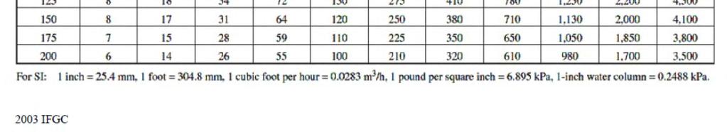
84 Natural Gas Pipe Sizing Sch. 40,.5 psi gas pressure,.3 w.c. pressure drop per 100, 84
85 85.5 psi w.c IFGC
86 Using Temp. Rise To Calculate CFM BTU Output Of Furnace CFM = X Temp. Rise Rules: limit must not cycle the burners off at any time, altitude of installation is between 0 and 1,000 feet above sea level, input is set precisely according to manufacturer s instructions (proper manifold pressure and orifice size), 86
87 CFM Example After the supply temperature stabilizes, your supply temperature is 106 O F and the return air temperature is 65 O F. Furnace is 80,000 input (gas pressure and orifices are correct), 72,000 output. Temperature rise shown on the rating plate is O F. Question: is the temperature rise O.K.? 87
88 Example Continued Yes! Calculate CFM Do this math first. CFM = Output (1.08 X Temp. Rise) = 72,000 (1.08 X 41) = 72, = 1,
89 Input, 2 nd Method Clock the meter to determine CFH (cubic feet of gas per hour). Pick smallest dial you can easily time for 1 complete revolution. Determine btu/cubic foot (BTU/CF) for the gas provided by your utility. Formula: 3600 X Dial Size CFH = Seconds Per Rev. 89
90 Meter Clocking (continued) Furnace or boiler input in BTU/Hr. Input = CFH X Heat Content of 1 CF Utility says heat content of their natural gas is 1,000 BTU/CF. 90
91 1/2 Cu.Ft. 1 Cu.Ft. 2 Cu.Ft. 5 Cu.Ft. Typical Gas Meter Education and Consulting, Ltd. 91
92 Meter Clocking (continued) Example: Dial Size selected is.5 cubic feet (cu. ft.) Time for 1 revolution is 18 seconds CFH = (3,600 X.5) 18 = 1, = 100 CFH Input = CFH X Heat Content per Cu. Ft. = 100 X 1,000 = 100,000 92
93 Setting Manifold Pressure (Nat. Gas) Verify inlet line pressure Determine outlet (manifold) pressure using: Heat content of one CF Altitude above sea level Specific gravity of the fuel Burner orifice size Used to calculate manifold pressure 93
94 94

95 2015 IFGC 95
96 Proper Venting Follow manufacturer s instructions. 96
97 Wiring Diagram Basics There are 2 types: Ladder (used mainly for service and determining the sequence of operation). Also called a schematic by some. Pictoral (used to show the location of components and provide a point-to-point wiring diagram). Difficult to use to determine sequence of operation. 97


98 PICTORAL DIAGRAM LADDER DIAGRAM 98
99 Category IV IID 90% AFUE Ladder Diagram L1 115 Volt Fused And Protected L2 Power Supply BDS SSU Switch Fused Disconnect Switch FR1 (NC) FR2 (NO) IMR1 Fan Sw. Line Voltage (115V) Low Voltage (24V) Heat Speed A/C Speed B M IM Common Tape Off Unused Speeds Separately Primary Transformer Htg./Clg. Stat ROS LIMIT FL Secondary GND Y G W R R IMR2 IMR IID Spark Box With Pre-Purge Timer W TH G C PS TR MV MV Y IMR3 PV PV Low Voltage Terminal Strip FR MV/PV Spark Gas Valve GND CC Copyright 2005 All Rights Reserved 777 Education and Consulting, Inc. 99
100 LEGEND BDS Blower Door Switch BM Blower Motor DSG Draft Safeguard Switch (manual reset) FL Fusible Link (3A) GND Ground IM Inducer Motor IMR Inducer Motor Relay LIMIT High Temp. Limit (auto reset) MV Main Valve MV/PV Common PS Pressure Switch PV Pilot Valve ROS Roll Out Switch (manual reset) TH Power IN From Transformer (Trans.) TR Common To Trans. 100
101 L1 115 Volt Fused And Protected L2 Power Supply SSU Switch Fused Disconnect Switch Line Voltage (115V) Low Voltage (24V) BDS FR1 (NC) Fan Sw. Heat Speed A/C Speed B M Common FR2 (NO) Tape Off Unused Speeds Separately IMR1 IM Transformer 24 V Copyright 2005 All Rights Reserved 777 Education and Consulting, Inc. 101
102 Htg./Clg. Stat Y G W R Transformer ROS LIMIT FL 115 V 24 V GND DSG R IMR2 IMR IID Spark Box With Pre-Purge Timer W TH G C PS TR MV MV Y IMR3 PV PV Low Voltage Terminal Strip FR MV/PV Spark Gas Valve GND CC Copyright 2005 All Rights Reserved 777 Education and Consulting, Inc. 102
103 103
104 Maintenance FOLLOW ALL MANUFACTURER INSTRUCTIONS the following is generic information only Inspect and change as necessary: Vent, drain, and duct system Heat exchangers Wiring and connections Filters All accessories Thermostat 104
105 Maintenance (Continued) Clean: Burners Blower wheel and motor Check: Safety lockout on all systems All system safety components Check for presence of CO and gas/oil leaks 105
106 Maintenance (Continued) Check (continued) : Combustion air Negative mechanical room pressurization Venting system Draft inducer and pressure switch operation Temperature rise Manifold pressure Flame with fan off, then with fan on Heat exchangers for holes or cracks For combustibles near the appliance 106

107 Maintenance (Continued) Complete all manufacturer recommended items Make recommendations to customer Run unit through a complete cycle COLLECT 107
108 Things To Watch Out For Temp. rise out of range. Gas pressure not set to mfg. specs. Secondary fin tube heat exchanger is dirty they make great air filters. Condensate leaks (furnace or evaporator coil). Low t stat set point. (For example, minimum recommended return air may be 55 O F intermittent / 60 O F continuous) 108

109 Useful Tips All Equipment Get equipment manufacturer s operation and service instructions before you need them. (Obtain full model, product, and serial numbers). Get web addresses. Get component manufacturer s name and part number off parts which you are not familiar with. Order the instructions before you need them. Get web addresses. 109

110 Thanks for your attention. It s Miller Time Copyright Education and Consulting 110
The ECM Textbook.
 Table of Contents - Overview of ECM Technology - Indoor Blower Motors o Variable Speed ECM o Constant Torque ECM The ECM Textbook www.thedealertoolbox.com About the Company When Regal Beloit acquired General
Cooling Capacity CFM in. w.c. (125 Pa)
") 92.1% AFUE, Single Stage, PSC Gas Furnace EASIER TO SELL 92.1% AFUE, all models all positions, California NOx approved Certified to leak 2% or less of nominal air conditioning CFM delivered when pressurized
92.1% AFUE, Single Stage, PSC Gas Furnace EASIER TO SELL 92.1% AFUE, all models all positions, California NOx approved Certified to leak 2% or less of nominal air conditioning CFM delivered when pressurized
Cooling Capacity CFM in. w.c. (125 Pa)
") 95.5% AFUE, Single Stage, PSC Gas Furnace EASIER TO SELL 95.5% AFUE, all models all positions, California NOx approved Certified to leak 2% or less of nominal air conditioning CFM delivered when pressurized
95.5% AFUE, Single Stage, PSC Gas Furnace EASIER TO SELL 95.5% AFUE, all models all positions, California NOx approved Certified to leak 2% or less of nominal air conditioning CFM delivered when pressurized
The ECM Textbook ECM. Table of Contents. - Overview of ECM Technology. - Indoor Blower Motors o Variable Speed ECM o Constant Torque ECM
 The ECM Textbook Table of Contents Overview of ECM Technology Indoor Blower Motors o Variable Speed ECM o Constant Torque ECM ECM PSC 2007 GE ECM by REGALBELOIT ECM Textbook Rev 1.4 This material has been
Cooling Capacity CFM in. w.c. (125 Pa)
") 92.1% AFUE, Single Stage, PSC Gas Furnace EASIER TO SELL 92.1% AFUE, all models all positions, California NOx approved Certified to leak 2% or less of nominal air conditioning CFM delivered when pressurized
92.1% AFUE, Single Stage, PSC Gas Furnace EASIER TO SELL 92.1% AFUE, all models all positions, California NOx approved Certified to leak 2% or less of nominal air conditioning CFM delivered when pressurized
N9MSB. PS 92 Product Specifications. 92.1% AFUE, Single Stage, PSC Gas Furnace EASIER TO SELL /2/17
 92.1% AFUE, Single Stage, PSC Gas Furnace EASIER TO SELL 92.1% AFUE all models in all positions California NOx approved Certified to leak 2% or less of nominal air conditioning CFM delivered when pressurized
Cooling Capacity CFM in. w.c. (125 Pa)
") 92.1% AFUE, Single Stage, PSC Gas Furnace EASIER TO SELL 92.1% AFUE, all models all positions, California NOx approved Certified to leak 2% or less of nominal air conditioning CFM delivered when pressurized
92.1% AFUE, Single Stage, PSC Gas Furnace EASIER TO SELL 92.1% AFUE, all models all positions, California NOx approved Certified to leak 2% or less of nominal air conditioning CFM delivered when pressurized
Cooling Capacity CFM in. w.c. (125 Pa)
") 95.5% AFUE, Single Stage, PSC Gas Furnace EASIER TO SELL 95.5% AFUE, all models all positions, California NOx approved Certified to leak 2% or less of nominal air conditioning CFM delivered when pressurized
95.5% AFUE, Single Stage, PSC Gas Furnace EASIER TO SELL 95.5% AFUE, all models all positions, California NOx approved Certified to leak 2% or less of nominal air conditioning CFM delivered when pressurized
Up to 96% AFUE, Single Stage, PSC Gas Furnace EASIER TO SELL
 N9MSE Product Specifications Up to 96% AFUE, Single Stage, PSC Gas Furnace EASIER TO SELL Up to 96% AFUE in upflow and horizontal positions, Up to 96% AFUE in downflow positions California NOx approved
Cooling Capacity CFM in. w.c. (125 Pa)
") N8MXL Product Specifications 80% ECM Single Stage Heating Furnace EASIER TO SELL 80% AFUE Flame roll out sensors standard Category I venting Blocked vent switch 24 VAC humidifier terminal Electronic air
N8MXL Product Specifications 80% ECM Single Stage Heating Furnace EASIER TO SELL 80% AFUE Flame roll out sensors standard Category I venting Blocked vent switch 24 VAC humidifier terminal Electronic air
WFAR. Product Specifications 92.1 AFUE GAS FURNACE MULTIPOISE DESIGN UPFLOW/DOWNFLOW/HORIZONTAL (NATURAL GAS) Heat Exchangers Warranty
 Heat Exchangers Warranty") 92.1 AFUE GAS FURNACE MULTIPOISE DESIGN WFAR Use of the AHRI Certified TM Mark indicates a manufacturer s participation in the program. For verification of certification for individual products, go to
92.1 AFUE GAS FURNACE MULTIPOISE DESIGN WFAR Use of the AHRI Certified TM Mark indicates a manufacturer s participation in the program. For verification of certification for individual products, go to
36H Gas Control Product Information
 Single Stage 36H Two Stage 36H 36H Gas Control Product Information The 36H combination gas control valve is a versatile multifunction control designed to meet the requirements for use with intermittent
G8MVL. Product Specifications
 80% Variable Speed, Two Stage Heating Furnace EASIER TO SELL 80% AFUE Supports two stage cooling units Flame roll out sensors standard Category I venting Blocked vent switch Dehumidification feature in
TSTAT0101SC Recommended (sold separately)
") Up to 96% AFUE, Communicating, Two Stage Gas Furnace EASIER TO SELL Up to 96% AFUE, all models, all positions California NOx approved All Models have earned the ENERGY STAR Two stage heating operation
Up to 96% AFUE, Communicating, Two Stage Gas Furnace EASIER TO SELL Up to 96% AFUE, all models, all positions California NOx approved All Models have earned the ENERGY STAR Two stage heating operation
INSTALLATION DATA 712 Series Pilot
 INSTALLATION DATA 712 Series Pilot Ignition Systems (FLAME RECTIFICATION) LOCKOUT MODEL 712-005 712-006 712-008 712-009 NON-LOCKOUT MODELS 712-005 712-016 712-017 712-019 712-022 CSA DESIGN CERTIFIED TO
WARNING WARNING WARNING WARNING WARNING WARNING WARNING
 ECM SERVICE GUIDE Genteq does not condone the repair of any individual components in the motor control or motor of their ECM products. This practice is unsafe and may cause personal injury, death, or property
Ruud Ultra Series Communicating Two-Stage Variable Speed Downflow Gas Furnace
 Gas Furnaces Ruud Ultra Series Communicating Two-Stage Variable Speed Downflow Gas Furnace U802V Downflow Series 80% A.F.U.E. Input Rates 75-125 kbtu A.F.U.E. (Annual Fuel Utilization Efficiency) calculated
W801T (Downflow) Series Models with Input Rates from 75 to 125 kbtu [15 to 37 kw] (80% A.F.U.E. )
![W801T (Downflow) Series Models with Input Rates from 75 to 125 kbtu [15 to 37 kw] (80% A.F.U.E. )](/thumbs/89/98206847.jpg "W801T (Downflow) Series Models with Input Rates from 75 to 125 kbtu [15 to 37 kw] (80% A.F.U.E. )") FORM NO. G66-549 REV. 3 Supersedes Form No. G66-536 Rev. 3 DOWNFLOW GAS FURNACE Features 80% residential Gas Furnace CSA certified 7 Segment LED all units Direct Spark Ignition System for reliability and
FORM NO. G66-549 REV. 3 Supersedes Form No. G66-536 Rev. 3 DOWNFLOW GAS FURNACE Features 80% residential Gas Furnace CSA certified 7 Segment LED all units Direct Spark Ignition System for reliability and
TZ80MSX (UPFLOW/ HORIZONTAL) SERIES Models with Input Rates from 50 to 125 kbtu [15 to 37 kw] FORM NO. GTZ-544 Supersedes Form No. GTZ-503 Rev.
![TZ80MSX (UPFLOW/ HORIZONTAL) SERIES Models with Input Rates from 50 to 125 kbtu [15 to 37 kw] FORM NO. GTZ-544 Supersedes Form No. GTZ-503 Rev.](/thumbs/95/124184082.jpg "TZ80MSX (UPFLOW/ HORIZONTAL) SERIES Models with Input Rates from 50 to 125 kbtu [15 to 37 kw] FORM NO. GTZ-544 Supersedes Form No. GTZ-503 Rev.") FORM NO. GTZ-544 Supersedes Form No. GTZ-503 Rev. 1 UPFLOW/ HORIZONTAL GAS FURNACES Features 80% residential Gas Furnace CSA certified 3 way multi poise design UF / HZ 7 Segment LED all units Direct Spark
FORM NO. GTZ-544 Supersedes Form No. GTZ-503 Rev. 1 UPFLOW/ HORIZONTAL GAS FURNACES Features 80% residential Gas Furnace CSA certified 3 way multi poise design UF / HZ 7 Segment LED all units Direct Spark
DUAL COMFORT CONTROL TWO-STAGE DOWNFLOW/HORIZONTAL GAS FURNACES WITH
 FORM NO. GSC-531 REV. 1 Supersedes Form No. GSC-488 Rev. 7 GF902D SERIES Models with Input Rates from 60 to 120 kbtu [17.58 to 35.17 kw] (All Models 92% A.F.U.E. or Above) TWO-STAGE DOWNFLOW/HORIZONTAL
Rheem Classic Plus Series Downflow Gas Furnace
 Gas Furnaces Rheem Classic Plus Series Downflow Gas Furnace R801T Downflow Series 80% A.F.U.E. Input Rates 75-125 kbtu A.F.U.E. (Annual Fuel Utilization Efficiency) calculated in accordance with Department
DM80SS / DD80SS. Single-Stage, Multi-Speed Gas Furnaces 80% AFUE Heating Input: 40, ,000 BTU/h
 / Single-Stage, Multi-Speed Gas Furnaces 80% AFUE Heating Input: 40,000 140,000 BTU/h Contents Nomenclature...2 Product Specifications...3 Dimensions...5 Airflow Data...8 Wiring Diagram...10 Accessories...11
WFSR. Product Specifications 95.5 AFUE GAS FURNACE MULTIPOISE DESIGN UPFLOW/DOWNFLOW/HORIZONTAL (NATURAL GAS) Heat Exchangers Warranty
 Heat Exchangers Warranty") 95.5 AFUE GAS FURNACE MULTIPOISE DESIGN WFSR Use of the AHRI Certified TM Mark indicates a manufacturer s participation in the program. For verification of certification for individual products, go to
95.5 AFUE GAS FURNACE MULTIPOISE DESIGN WFSR Use of the AHRI Certified TM Mark indicates a manufacturer s participation in the program. For verification of certification for individual products, go to
G9MXE. Product Specifications
 Up to 96% AFUE, Single Stage, ECM Gas Furnace EASIER TO SELL Up to 96% AFUE, all models all positions California NOx approved Select models earn the ENERGY STAR (See below, indicated with check mark.)
FORM NO. GTZ-542 Supersedes Form No. GTZ-503 Rev. 1
 FORM NO. GTZ-542 Supersedes Form No. GTZ-503 Rev. 1 TZ80MSS (UPFLOW/ HORIZONTAL) SERIES Models with Input Rates from 50 to 150 kbtu [15 to 44 kw] UPFLOW/ HORIZONTAL GAS FURNACES Features 80% residential
Rheem Prestige Series Communicating Two-Stage Variable Speed Upflow/Horizontal Gas Furnace
 Gas Furnaces Rheem Prestige Series Communicating Two-Stage Variable Speed Upflow/Horizontal Gas Furnace R802V- Upflow/Horizontal Series 80% A.F.U.E. Input Rates 50-125 kbtu A.F.U.E. (Annual Fuel Utilization
W801S (Downflow) SERIES Models with Input Rates from 50 to 150 kbtu [15 to 44 kw] (80% A.F.U.E. )
![W801S (Downflow) SERIES Models with Input Rates from 50 to 150 kbtu [15 to 44 kw] (80% A.F.U.E. )](/thumbs/81/82939397.jpg "W801S (Downflow) SERIES Models with Input Rates from 50 to 150 kbtu [15 to 44 kw] (80% A.F.U.E. )") FORM NO. G66-547 REV. 4 Supersedes Form No. G66-536 Rev. 3 DOWNF GAS FURNACE Features 80% residential Gas Furnace CSA certified 7 Segment LED all units Direct spark ignition for reliability and longevity
FORM NO. G66-547 REV. 4 Supersedes Form No. G66-536 Rev. 3 DOWNF GAS FURNACE Features 80% residential Gas Furnace CSA certified 7 Segment LED all units Direct spark ignition for reliability and longevity
G9MXE. Product Specifications
 Up to 96% AFUE, Single Stage, ECM Gas Furnace EASIER TO SELL Up to 96% AFUE, all models all positions California NOx approved Select models earn the ENERGY STAR (See below, indicated with check mark.)
AMS8 / ADSS8. Single-Stage Multi-Speed Gas Furnaces 80% AFUE. Heating Input: 40, ,000 BTU/h
 / ADSS8 Heating Input: 40,000 140,000 BTU/h Single-Stage Multi-Speed Gas Furnaces 80% AFUE Contents Nomenclature...2 Product Specifications...3 Dimensions...5 Airflow Data...7 Wiring Diagrams...10 Accessories...11
36C and 36D Gas Control Product Information
 6C and 6D Gas Control Product Information The 6C and 6D combination gas control valves are compact multifunction controls designed to meet requirements for use with Standing Pilot systems and all types
Rheem Classic Series Downflow Gas Furnace
 Gas Furnaces Rheem Classic Series Downflow Gas Furnace R801S (Downflow) Series 80% A.F.U.E. Input Rates 50-150 kbtu A.F.U.E. (Annual Fuel Utilization Efficiency) calculated in accordance with Department
BLOWER VACUUM SWITCH FAILED OPEN
 F1 F1 AC BLOWER VACUUM SWITCH FAILED CLOSED AC BLOWER VACUUM SWITCH FAILED CLOSED UHS If the blower vacuum switch is closed before blower start-up, the control module will not start the blower. Pre-check
KG7T (C and L Series)
") TECHNICAL SPECIFICATIONS KG7T (C and L Series) Two Stage, Fixed Speed ECM, Condensing Upflow/Horizontal and Downflow Gas Furnaces Induced Draft - 95.1 AFUE Input 60,000-120,000 Btuh The high efficiency
TECHNICAL SPECIFICATIONS KG7T (C and L Series) Two Stage, Fixed Speed ECM, Condensing Upflow/Horizontal and Downflow Gas Furnaces Induced Draft - 95.1 AFUE Input 60,000-120,000 Btuh The high efficiency
TECHNICAL SERVICE DEPARTMENT Technical Service Bulletin LowNOx Commercial Gas Electronic Spark Ignition Sequence
 The Universal TM gas LowNOx series water heaters contain an electronic spark ignition system. The heater is connected to a 120VAC power source required by the transformer. The transformer steps down the
GUH 95 Series TECHNICAL SPECIFICATIONS. FEATURES and BENEFITS
 TECHNICAL SPECIFICATIONS GUH 95 Series Two Stage, Variable Speed, Condensing Upflow/Horizontal and Downflow Gas Furnaces Induced Draft - 95.1 AFUE Input 60,000-120,000 Btuh The high efficiency upflow gas
Rheem Classic Plus Series Upflow/Horizontal Gas Furnace
 Gas Furnaces Rheem Classic Plus Series Upflow/Horizontal Gas Furnace R801T- Upflow/Horizontal Series 80% A.F.U.E. Input Rates 50-125 kbtu A.F.U.E. (Annual Fuel Utilization Efficiency) calculated in accordance
W801T (UPFLOW/ HORIZONTAL) SERIES Models with Input Rates from 50 to 125 kbtu (80% A.F.U.E. )
 SERIES Models with Input Rates from 50 to 125 kbtu (80% A.F.U.E. )") FORM NO. G66-544 REV. 4 Supersedes Form No. G66-536 Rev. 3 W801T (UPFLOW/ HORIZONTAL) SERIES Models with Input Rates from 50 to 125 kbtu (80% A.F.U.E. ) UPFLOW/ HORIZONTAL GAS FURNACES Features 80% residential
FORM NO. G66-544 REV. 4 Supersedes Form No. G66-536 Rev. 3 W801T (UPFLOW/ HORIZONTAL) SERIES Models with Input Rates from 50 to 125 kbtu (80% A.F.U.E. ) UPFLOW/ HORIZONTAL GAS FURNACES Features 80% residential
G23 Bulletin # September 1998 Supersedes June 1995
 ENGINEERING DATA ELITE 80Z UP-FLOW GAS FURNACES *80.0% to 80.8% A.F.U.E. 50,000 to 150,000 Btuh (14.7 to 44.0 kw) Gas Heating Input 1 thru 6 Tons (3.5 thru 21.1 kw) Nominal Add-On Cooling *Isolated Combustion
BG1600M Intermittent Pilot Ignition Control
 Installation Instructions Issue Date March, 00 BG600M Intermittent Pilot Ignition Control Application The BG600M Intermittent Pilot Ignition Control is a safety control designed for indirect burner ignition
Product Data. S Variable-speed ECM blower motor. S Two heating stages. S Humidity control when using a humidity sensing thermostat
 PG8MVA PG8JVA 4 --- WAY MULTIPOISE INDUCED---COMBUSTION GAS FURNACE INPUT CAPACITIES: 70,000 thru 135,000 Btuh SERIES A Product Data multipoise design, through -the-furnace downflow venting, 13 different
Ruud Achiever Plus Series Upflow/Horizontal Gas Furnace
 Gas Furnaces Ruud Achiever Plus Series Upflow/Horizontal Gas Furnace R802P- Upflow/Horizontal Series 80% A.F.U.E. Input Rates 50-150 kbtu A.F.U.E. (Annual Fuel Utilization Efficiency) calculated in accordance
Product Data. that this product meets the S 95% AFUE S Two -stage operation
 DIRECT VENT 4 -WAY MULTIPOISE CONDENSING GAS FURNACE 95% DOWNFLOW / HORIZONTAL ORIENTATIONS 93.5% UPFLOW ORIENTATION 95% Variable Speed Two -Stage Heating Furnace FLEXIBILITY S Supports two -stage cooling
Rheem Classic Series Upflow/Horizontal Gas Furnace
 THIS MODEL Air Gas Furnaces Rheem Classic Series Upflow/Horizontal Gas Furnace R801S- (Upflow/Horizontal) Series 80% A.F.U.E. Input Rates 50-150 kbtu ENER UIDE Annual Fuel Utilization Efficiency - AFUE
WFAR. Product Specifications 92.1 AFUE GAS FURNACE MULTIPOISE DESIGN
 92.1 AFUE GAS FURNACE MULTIPOISE DESIGN WFAR Use of the AHRI Certified TM Mark indicates a manufacturer s participation in the program. For verification of certification for individual products, go to
W801S (UPFLOW/ HORIZONTAL) SERIES Models with Input Rates from 50 to 150 kbtu [15 to 44 kw] (80% A.F.U.E. )
![W801S (UPFLOW/ HORIZONTAL) SERIES Models with Input Rates from 50 to 150 kbtu [15 to 44 kw] (80% A.F.U.E. )](/thumbs/84/89102330.jpg "W801S (UPFLOW/ HORIZONTAL) SERIES Models with Input Rates from 50 to 150 kbtu [15 to 44 kw] (80% A.F.U.E. )") FORM NO. G66-542 REV. 4 Supersedes Form No. G66-536 Rev. 3 W801S (UPFLOW/ HORIZONTAL) SERIES Models with Input Rates from 50 to 150 kbtu [15 to 44 kw] (80% A.F.U.E. ) UPFLOW/ HORIZONTAL GAS FURNACES Features
FORM NO. G66-542 REV. 4 Supersedes Form No. G66-536 Rev. 3 W801S (UPFLOW/ HORIZONTAL) SERIES Models with Input Rates from 50 to 150 kbtu [15 to 44 kw] (80% A.F.U.E. ) UPFLOW/ HORIZONTAL GAS FURNACES Features
Product Data. 95% AFUE Single Stage Furnace Upflow / Downflow / Horizontal. ama 58HDX COMFORT 95 DIRECT OR NON---DIRECT VENT CONDENSING GAS FURNACE
 COMFORT 95 DIRECT OR NON---DIRECT VENT 4 --- WAY MULTIPOISE CONDENSING GAS FURNACE 95% AFUE Single Stage Furnace Upflow / Downflow / Horizontal FLEXIBILITY S Dual certified venting (1 or 2 pipes) Direct
Rheem Classic Plus Series Upflow/Horizontal Gas Furnace
 Gas Furnaces Rheem Classic Plus Series Upflow/Horizontal Gas Furnace R801T- Upflow/Horizontal Series 80% A.F.U.E. Input Rates 50-125 kbtu A.F.U.E. (Annual Fuel Utilization Efficiency) calculated in accordance
Rheem Classic Series Upflow/Horizontal Gas Furnace
 Gas Furnaces Rheem Classic Series Upflow/Horizontal Gas Furnace R801P- Upflow/Horizontal Series 80% A.F.U.E. Input Rates 50-150 kbtu A.F.U.E. (Annual Fuel Utilization Efficiency) calculated in accordance
UPFLOW/ HORIZONTAL GAS FURNACE
 FORM NO. GFJ-542 UPFLOW/ HORIZONTAL GAS FURNACE Features 80% residential Gas Furnace CSA certified 3 way multi poise design UF / HZ 7 Segment LED all units Direct Spark Ignition for reliability and longevity
AMS8/ADSS8. Single-Stage. Heating Input: 40, ,000 BTU/h
 Heating Input: 40,000 140,000 BTU/h /ADSS8 Single-Stage Multi-Speed Gas Furnaces 80% AFUE Standard Features Single-stage gas valve Durable Silicon Carbide ignitor Quiet, single-speed draft inducer Self-diagnostic
WFEL. Product Specifications. 80% AFUE GAS FURNACE Multipoise Design
 80% AFUE GAS FURNACE Multipoise Design WFEL Use of the AHRI Certified TM Mark indicates a manufacturer s participation in the program. For verification of certification for individual products, go to www.ahridirectory.org.
GMS8/GDS8/GHS8. Single-Stage, Multi-Speed, Multi-Position Gas Furnace 80% AFUE. Heating Input : 40, ,000 BTU/h
 // Heating Input : 40,000 140,000 BTU/h Single-Stage, Multi-Speed, Multi-Position Gas Furnace 80% AFUE Contents Nomenclature... 2 Product Specifications... 3 Dimensions... 5 Airflow Data... 8 Wiring Diagrams...
GAS FURNACES CLASSIC SERIES SUPER QUIET 80 80% A.F.U.E. DOWNFLOW GAS FURNACES
 FORM NO. G11-487 REV. 1 Supersedes Form No. G11-487 Rev. 8 GAS FURNACES RGLN- SERIES Models with Input Rates from 50,000 to 150,000 BTU/HR [15 to 44 kw] (U.S. & Canadian Models) Annual Fuel Utilization
80% A.F.U.E. UPFLOW/ HORIZONTAL GAS FURNACES
 FORM NO. G66-495 Supersedes Form No. P66-765 Rev. 3 80PS- SERIES Models with Input Rates from 50,000 to 150,000 BTU/HR [15 to 44 kw] 80% A.F.U.E. UPF/ HORIZONTAL GAS FURNACES The WeatherKing line of upflow/horizontal
Table of Contents GF801U Series
 FORM NO. GSC-520 GF801U SERIES Models with Input Rates from 50 to 150 kbtu [15 to 44 kw] 80% A.F.U.E. UPFLOW/ HORIZONTAL GAS FURNACES The Sure Comfort line of upflow/horizontal gas furnaces are designed
VMS8/VDS8. Single-Stage, Single Speed, Multi-Position Gas Furnace 80% AFUE. Heating Input : 40, ,000 BTU/h
 / Heating Input : 40,000 100,000 BTU/h Single-Stage, Single Speed, Multi-Position Gas Furnace 80% AFUE Contents Nomenclature... 2 Product Specifications... 3 Dimensions... 5 Airflow Data... 8 Wiring Diagrams...
RESIDENTIAL ELECTRONIC IGNITION SYSTEMS
 Service Application Manual SAM Chapter 630-153 Section 12 RESIDENTIAL ELECTRONIC IGNITION SYSTEMS by Marcus G. Metoyer, Jr., CMS INTRODUCTION The information contained in this publication is generic in
WAC Air Curtains Technical Guide
 TGWAC-2 WAC Air Curtains Technical Guide FOR WIND STOPPING, INSECT CONTROL, AND ENVIRONMENTAL SEPARATION IN COMMERCIAL AND INDUSTRIAL APPLICATIONS TABLE OF CONTENTS Introduction......................................................................2
WFEL. Product Specifications. 80% AFUE GAS FURNACE Multipoise Design
 80% AFUE GAS FURNACE Multipoise Design WFEL Use of the AHRI Certified TM Mark indicates a manufacturer s participation in the program. For verification of certification for individual products, go to www.ahridirectory.org.
X4 Installation and Operation Manual - POWER FLAME INCORPORATED
 7.13.2 Set the burner s combustion air inlet damper to the approximate setting as shown in this manual for the desired firing rate. Also, verify that the correct main orifice is installed in the main orifice
G95V Series Gas-Fired 95% 2-Stage High Efficiency (Condensing) Multi-Positional Furnace w/ ECM Circulator
 Multi-Positional Furnace w/ ECM Circulator") 5/23/07 G95V Service Parts 1 Key No. Description Cabinet Group Top Panel Left Side Panel Assembly Right Side Panel Assembly Rear Panel Blower Division Panel Assembly,,, Base Panel,, Upper Front Door Panel,
5/23/07 G95V Service Parts 1 Key No. Description Cabinet Group Top Panel Left Side Panel Assembly Right Side Panel Assembly Rear Panel Blower Division Panel Assembly,,, Base Panel,, Upper Front Door Panel,
Rheem Value Series Downflow Gas Furnace
 THIS MODEL 80.0% 78% 82% 88% 97% Air Gas Furnaces Rheem Value Series Downflow Gas Furnace RGLS- Series 80% A.F.U.E. Input Rates 50-150 kbtu ENER UIDE Annual Fuel Utilization Efficiency - AFUE MID A.F.U.E.
KG7T (E and N Series)
") TECHNICAL SPECIFICATIONS KG7T (E and N Series) Two Stage, Fixed Speed ECM, Condensing Upflow and Downflow Gas Furnaces Induced Draft - 96% AFUE Input 60,000-115,000 Btuh The high efficiency upflow gas
TECHNICAL SPECIFICATIONS KG7T (E and N Series) Two Stage, Fixed Speed ECM, Condensing Upflow and Downflow Gas Furnaces Induced Draft - 96% AFUE Input 60,000-115,000 Btuh The high efficiency upflow gas
Rheem Classic Plus Series Upflow/Horizontal Ultra Low NOx Gas Furnace
 Gas Furnaces Rheem Classic Plus Series Upflow/Horizontal Ultra Low NOx Gas Furnace R801T- Upflow/Horizontal Series 80% A.F.U.E. Input Rates 50-100 kbtu A.F.U.E. (Annual Fuel Utilization Efficiency) calculated
Rheem Classic Series Two-Stage Downflow/Horizontal Gas Furnace
 Gas Furnaces Rheem Classic Series Two-Stage Downflow/Horizontal Gas Furnace RGTK- Series 92% A.F.U.E. or Above 60-120 kbtu with Dual Comfort Control A.F.U.E. (Annual Fuel Utilization Efficiency) calculated
FG7T (E and N Series)
") TECHNICAL SPECIFICATIONS FG7T (E and N Series), Smartlite Two Stage, Fixed Speed ECM, High Efficiency Upflow and Downflow Gas Furnaces Induced Draft - 96% AFUE Input 60,000-115,000 Btuh The high efficiency
TECHNICAL SPECIFICATIONS FG7T (E and N Series), Smartlite Two Stage, Fixed Speed ECM, High Efficiency Upflow and Downflow Gas Furnaces Induced Draft - 96% AFUE Input 60,000-115,000 Btuh The high efficiency
GF802D SERIES Models with Input Rates from 50 to 150 kbtu [15 to 44 kw] (U.S. & Canadian Models)
![GF802D SERIES Models with Input Rates from 50 to 150 kbtu [15 to 44 kw] (U.S. & Canadian Models)](/thumbs/74/71367959.jpg "GF802D SERIES Models with Input Rates from 50 to 150 kbtu [15 to 44 kw] (U.S. & Canadian Models)") FORM NO. GSC-515 GF802D SERIES Models with Input Rates from 50 to 150 kbtu [15 to 44 kw] (U.S. & Canadian Models) TWO STAGE DOWNFLOW GAS FURNACES The Sure Comfort 2-Stage line of downflow gas furnaces
FORM NO. GSC-515 GF802D SERIES Models with Input Rates from 50 to 150 kbtu [15 to 44 kw] (U.S. & Canadian Models) TWO STAGE DOWNFLOW GAS FURNACES The Sure Comfort 2-Stage line of downflow gas furnaces
F8MTL. Product Specifications
 80% Two Stage Heating Furnace EASIER TO SELL 80% AFUE Suppts two stage cooling units Flame roll out senss standard Categy I venting Blocked vent switch Dehumidification feature in cooling 24 VAC and 115
TECHNICAL SPECIFICATIONS. FEATURES and BENEFITS WARRANTY
 TECHNICAL SPECIFICATIONS KG7S (C and L Series) High Efficiency / Direct Vent or Non Direct Vent Condensing Upflow/Horizontal and Downflow Gas Furnaces Induced Draft - 92. AFUE Input 38,000-20,000 Btuh
DD80HS. Two-Stage, Convertible Multi-Speed Gas Furnace 80% AFUE. Heating Input: 40, ,000 BTU/h
 Two-Stage, Convertible Multi-Speed Gas Furnace 80% AFUE Heating Input: 40,000 100,000 BTU/h Contents Nomenclature...2 Product Specifications...3 Dimensions...4 Airflow Data...5 Wiring Diagram...7 Accessories...8
KG7T (C and L Series)
") TECHNICAL SPECIFICATIONS KG7T (C and L Series) Two Stage, Fixed Speed ECM, Condensing Upflow/Horizontal and Downflow Gas Furnaces Induced Draft - 95.1 AFUE Input 60,000-120,000 Btuh The high efficiency
TECHNICAL SPECIFICATIONS KG7T (C and L Series) Two Stage, Fixed Speed ECM, Condensing Upflow/Horizontal and Downflow Gas Furnaces Induced Draft - 95.1 AFUE Input 60,000-120,000 Btuh The high efficiency
80% A.F.U.E. DOWNFLOW GAS FURNACES
 FORM NO. G66-496 REV. 5 Supersedes Form No. G66-496 Rev. 4 RGLS- SERIES Models with Input Rates from 50,000 to 150,000 BTU/HR [15 to 44 kw] (U.S. & Canadian Models) 80% A.F.U.E. DOWNF GAS FURNACES The
GAS FURNACES CLASSIC SERIES SUPER QUIET % A.F.U.E. UPFLOW/ HORIZONTAL GAS FURNACES
 FORM NO. G11-485 REV. 5 Supersedes Form No. G11-485 Rev. 4 GAS FURNACES RGPN- SERIES Models with Input Rates from 50,000 to 150,000 BTU/HR [15 to 44 kw] (U.S. & Canadian Models) ISO 9001:2000 Annual Fuel
GMS8/GDS8/GHS8 Multi-Position, Multi-Speed Gas Furnaces
 Heating Input: 40,000 140,000 TU/h //GHS8 Multi-Position, Multi-Speed Gas Furnaces 80% AFUE Standard Features Dual-diameter tubular heat exchanger Single-stage combination redundant gas valve Norton hot
SERVICE MANUAL (INTERNATIONAL)
") SERVICE MANUAL (INTERNATIONAL) IMPINGER CONVEYOR OVENS MODEL 1433-000-E, 1434-000-E, 1456, 1457 WITH PUSH BUTTON CONTROLS Lincoln Foodservice Products, LLC 1111 North Hadley Road Fort Wayne, Indiana 46804
SERVICE MANUAL (INTERNATIONAL) IMPINGER CONVEYOR OVENS MODEL 1433-000-E, 1434-000-E, 1456, 1457 WITH PUSH BUTTON CONTROLS Lincoln Foodservice Products, LLC 1111 North Hadley Road Fort Wayne, Indiana 46804
Cooling Capacity Dimensions H x W x D CFM range Inches in. w.c. (125 Pa)
") 80% Single Stage Heating Furnace EASIER TO SELL 80% AFUE Flame roll out senss standard Categy I venting Blocked vent switch Louvered do 24 VAC and 115 VAC humidifier terminal Electronic air cleaner terminal
80% Single Stage Heating Furnace EASIER TO SELL 80% AFUE Flame roll out senss standard Categy I venting Blocked vent switch Louvered do 24 VAC and 115 VAC humidifier terminal Electronic air cleaner terminal
80 PLUS A.F.U.E. UPFLOW/HORIZONTAL GAS FURNACES
 FORM NO. G66-478 REV. 5 Supersedes Form No. G66-478 Rev. 4 80PJ SERIES Models with Input Rates from 50,000 to 150,000 BTU/HR [15 to 44 kw] 80 PLUS A.F.U.E. UPF/HORIZONTAL GAS FURNACES Features The WeatherKing
EVER EFFICIENT. EVER RELIABLE. EVER PROFITABLE.
 EVER EFFICIENT. EVER RELIABLE. EVER PROFITABLE. A Regal Brand EVERGREEN SOLUTIONS Powered by ECM Technology Upgrade/Replace PSC motors with Evergreen IM Residential/Light Commercial HVAC Systems Reduce
Cooling Capacity Dimensions H x W x D CFM range Inches in. w.c. (125 Pa)
") 80% Single Stage Heating Furnace EASIER TO SELL 80% AFUE Flame roll out senss standard Categy I venting Blocked vent switch Louvered do 24 VAC and 115 VAC humidifier terminal Electronic air cleaner terminal
80% Single Stage Heating Furnace EASIER TO SELL 80% AFUE Flame roll out senss standard Categy I venting Blocked vent switch Louvered do 24 VAC and 115 VAC humidifier terminal Electronic air cleaner terminal
TECHNICAL GUIDE. Echelon MODELS: FC8S GAS-FIRED HIGH EFFICIENCY SINGLE STAGE DOWNFLOW FURNACES 80% AFUE DESCRIPTION WARRANTY FEATURES
 TECHNICAL GUIDE Echelon MODELS: FC8S GAS-FIRED HIGH EFFICIENCY SINGLE STAGE DOWNFLOW FURNACES 80% AFUE NATURAL GAS 40-130 MBH INPUT EFFICIENCY RATING CERTIFIED DESCRIPTION These high efficiency, dedicated
G600 Series Replacement Intermittent Pilot Ignition Controls
 Installation Instructions G600 Issue Date 0601 G600 Series ment Intermittent Pilot Ignition Controls Installation IMPORTANT: These instructions are intended as a guide for qualified personnel installing
Q35 Series Automatic Vent Damper System
 Installation Sheets Manual 121 Energy Conservation and Miscellaneous Kits Section Q Technical Bulletin Q35 Issue Date 0999 Q35 Series Automatic Vent Damper System Figure 1: Q35 Automatic Vent Damper System
TECHNICAL GUIDE AFFINITY MODELS: PS8 GAS-FIRED HIGH EFFICIENCY SINGLE STAGE DOWNFLOW FURNACES 80% AFUE DESCRIPTION WARRANTY FEATURES
 TECHNICAL GUIDE AFFINITY MODELS: PS8 GAS-FIRED HIGH EFFICIENCY SINGLE STAGE DOWNFLOW FURNACES 80% AFUE NATURAL GAS 40-130 MBH INPUT EFFICIENCY RATING CERTIFIED DESCRIPTION These high efficiency, dedicated
AF90. AF90 Gas Furnace High Efficiency. Features
 AF90 AF90 Gas Furnace High Efficiency Features Up to 92.1% AFUE Heating size range 50,000 125,000 BTUH 1-1/2 5 tons cooling capacity supported Twenty-year limited warranty on heat exchanger Five-year warranty
TECHNICAL GUIDE MODELS: G8T-UP 80 AFUE UPFLOW/HORIZONTAL GAS-FIRED FURNACES DESCRIPTION WARRANTY FEATURES Rev.
 TECHNICAL GUIDE MODELS: G8T-UP 80 AFUE UPFLOW/HORIZONTAL GAS-FIRED FURNACES 40-130 MBH INPUT HIGH-EFFICIENCY INDUCED COMBUSTION EFFICIENCY RATING CERTIFIED This product was manufactured in a plant whose
Rheem Classic Plus Super Quiet 80 Upflow/Horizontal Gas Furnace
 THIS MODEL 80.0% 78% 82% 88% 97% Air Gas Furnaces Rheem Classic Plus Super Quiet 80 Upflow/Horizontal Gas Furnace RGPT- Series 80% A.F.U.E. Input Rates 50-125 kbtu ENER UIDE Annual Fuel Utilization Efficiency
E Series CE Approved Intermittent Pilot Ignition Control
 Installation Instructions Issue Date January 11, 2013 E Series CE Approved Intermittent Pilot Ignition Control Application The E Series CE Approved Intermittent Pilot Ignition Control is a safety control
G21Q Bulletin # September 1992 Supersedes March 1992
 ENGINEERING DATA Typical Applications G21Q PULSE21 SERIES UP-FLO GAS FURNACES *93.2% to 96.2% A.F.U.E. 40,000 to 100,000 Btuh Input Add-On Cooling 1-1/2 thru 5 Nominal Tons *Isolated Combustion System
Troubleshooting Manual
 Troubleshooting Manual NOTICE: DO NOT DISCARD THIS MANUAL Models: LEGACY42-IFT PHOENIX42-IFT 1 TABLE OF CONTENTS A. Normal Operation...3 B. Wiring Diagram...4 C. Troubleshooting IntelliFire Touch...5 D.
GAS FURNACES ACHIEVER SERIES SUPER QUIET % A.F.U.E. UPFLOW/ HORIZONTAL GAS FURNACES
 FORM NO. G22-485 REV. 4 Supersedes Form No. G22-485 Rev. 3 GAS FURNACES UGPN- SERIES Models with Input Rates from 50,000 to 150,000 BTU/HR [15 to 44 kw] (U.S. & Canadian Models) Annual Fuel Utilization
Rheem Value Series Upflow/Horizontal Gas Furnace
 THIS MODEL Gas Furnaces Rheem Value Series Upflow/Horizontal Gas Furnace RGPS- Series 80% A.F.U.E. Input Rates 50-150 kbtu ENER UIDE Annual Fuel Utilization Efficiency - AFUE 80.0% MID HIGH 78% 82% 88%
Applies to: Models F, B, FE, and BE with spark pilot
 Form CP-F/B-GC (11/17) R8 Obsoletes Form CP-F/B-GC (Version A.2) Gas Conversion Kits and Instructions Applies to: Models F, B, FE, and BE with spark pilot NOTE: Units with standing (match - lit) pilots
VG7S (D and M Series) High Efficiency, Single Stage Condensing Upflow/Horizontal and Downflow Gas Furnace Models 95.0 AFUE 38, ,000 Btuh Input
 High Efficiency, Single Stage Condensing Upflow/Horizontal and Downflow Gas Furnace Models 95.0 AFUE 38, ,000 Btuh Input") TECHNICAL SPECIFICATIONS VG7S (D and M Series) High Efficiency, Single Stage Condensing Upflow/Horizontal and Downflow Gas Furnace Models 95.0 AFUE 38,000-120,000 Btuh Input The high efficiency upflow
TECHNICAL SPECIFICATIONS VG7S (D and M Series) High Efficiency, Single Stage Condensing Upflow/Horizontal and Downflow Gas Furnace Models 95.0 AFUE 38,000-120,000 Btuh Input The high efficiency upflow
Achieve Up To 200% Greater Efficiency And Better Air Flow Performance With GE ECM Technology
 Achieve Up To 200% Greater Efficiency And Better Air Flow Performance With GE ECM Technology GE ECM 2.3 ECM X13 What's an ECM? The highest efficiency motor there is! essentially a DC Motor Without mechanical
GAS FURNACES QUIET 80 80% A.F.U.E. UPFLOW/ HORIZONTAL GAS FURNACES
 FORM NO. G11-486 REV. 3 Supersedes Form No. G11-486 Rev. 2 GAS FURNACES RGPP- SERIES Models with Input Rates from 50,000 to 150,000 BTU/HR [15 to 44 kw] (U.S. & Canadian Models) ISO 9001:2000 Annual Fuel
Installation, Operation and Maintenance Manual
 Document 481038 Model PVF(-H) and PVG Indirect Gas-Fired Heat Modules Indirect Gas-Fired Furnaces Installation, Operation and Maintenance Manual Please read and save these instructions for future reference.
100% OUTSIDE AIR MAKE-UP UNITS WITH DISCHARGE TEMPERATURE CONTROL & c.pco DIRECT DIGITAL CONTROL MODULE
 100% OUTSIDE AIR MAKE-UP UNITS WITH DISCHARGE TEMPERATURE CONTROL & c.pco DIRECT DIGITAL CONTROL MODULE Start-up must be performed by a trained, experienced service person. The following general start-up
G72x Series Direct Spark Ignition Controls
 Installation Sheets Manual 121 Gas Combustion Combination Controls and Systems Section G Technical Bulletin G72x Issue Date 1299 G72x Series Direct Spark Ignition Controls Figure 1: G72x Direct Spark Ignition
Installation, Operation and Maintenance Manual
 Document 481038 Model PVF and PVG Indirect Gas-Fired Heat Modules Indirect Gas-Fired Furnaces Installation, Operation and Maintenance Manual Please read and save these instructions for future reference.
G21Q ENGINEERING DATA. Typical Applications. Bulletin # March 1993
 ENGINEERING DATA ENGINEERING DATA MATCHED REMOTE GAS FURNACES SYSTEMS 50hz G21Q PULSE21 SERIES UP-FLO GAS FURNACES 11.4 to 27.8 kw (39 000 to 95 000 Btuh) Output Add-On Cooling 5.3 thru 17.6 kw (1-1/2