Installation, Operation & Maintenance Instruction. Models: FMP Series 30, 40, 50. PeriFlo FMP PERISTALTIC PUMP. Bulletin #: IOM-PFL-4502
|
|
|
- Barbara Pope
- 5 years ago
- Views:
Transcription

1 Installation, Operation & Maintenance Instruction Models: FMP Series 30, 40, 50 Bulletin #: IOM-PFL-4502 PeriFlo FMP PERISTALTIC PUMP
2 Pulsafeeder Factory Service Policy Should you experience a problem with your PeriFlo FMP pump, first consult the troubleshooting guide in your operation and maintenance manual. If the problem is not covered or cannot be solved, please contact your local Pulsafeeder Sales Representative or our Technical Services Department for further assistance. Trained technicians are available to diagnose your problem and arrange a solution. Solutions may include purchase of replacement parts or returning the unit to the factory for inspection and repair. All returns require a Return Authorization number to be issued by Pulsafeeder. Warranty parts returned as defective, which test good, will be sent back freight collect. No credit will be issued on any replacement electronic parts. Pulsafeeder s Factory Service Policy is maintained online. Please source this document at this URL: All Pulsafeeder PeriFlo manufactured products are guaranteed against defects in materials and workmanship under normal use for 12 months from the date of shipment from the factory. Any modifications or out-of-warranty repairs will be subject to bench fees and costs associated with replacement parts. Safety Considerations: 1. Read and understand all related instructions and documentation before attempting to install or maintain this equipment. 2. Observe all special instructions, notes, and cautions. 3. Act with care and exercise good common sense and judgment during all installation, adjustment, and maintenance procedures. 4. Ensure that all safety and work procedures and standards that are applicable to your company and facility are followed during the installation, maintenance, and operation of this equipment. Trademarks PeriFlo is registered trademark of Pulsafeeder Inc. Pulsafeeder is a registered trademark of Pulsafeeder, Inc. Copyright 2014 Pulsafeeder, Inc. All rights reserved. Information in this document is subject to change without notice. No part of this publication may be reproduced, stored in a retrieval system or transmitted in any form or any means electronic or mechanical, including photocopying and recording for any purpose other than the purchaser s personal use without the written permission of Pulsafeeder, Inc. ii
3 Table of Contents 1. EQUIPMENT INSPECTION General Description Construction of the Pump Storage Instructions INSTALLATION Location Motor Piping System Discharge Pressure Requirements EQUIPMENT STARTUP Fastener Inspection Pump Inspection Preliminary Checks Calibration MAINTENANCE Hose/Tube Inspection, Removal, & Reinstallation Lubrication Hose/Tube Compression and Shimming Motor Removal & Reinstallation REPLACEMENT PARTS TROUBLESHOOTING PIPING ACCESSORIES DIMENSIONAL DRAWING FMP FMP FMP iii
4 1. Equipment Inspection Check all equipment for completeness against the order and for any evidence of shipping damage. Shortages or damage must be reported immediately to the carrier and your authorized representative or distributor of PeriFlo pumps. Included Items: PeriFlo FMP Peristaltic Pump Optional Items: Motor (pre-installed at the factory) Leak Detection Controls Package Spare Hoses, Grease or Oil, and Shims 1.1 General Description The PeriFlo peristaltic pump is constructed with simple yet robust components designed to create continuous, repetitive, positive flow. Modern materials are used to meet the needs of the toughest jobs from aggressive chemicals to highly abrasive slurries. 1.2 Construction of the Pump The diagram below highlights the four main components of the PeriFlo FMP peristaltic pump. The outer casing (Item 1) contains the pump components and supports the hose/tube. Inside the casing, the rotor (Item 2) supports the two rollers (Items 3). As the rotor turns, the rollers compress the hose/tube (Item 4) to create suction and generate the pumping action. A change in rotor direction will result in a change in direction of the pumped fluid. Figure 1 - Construction of Pump 1
5 Hoses are defined as the flexible element for fluid transfer comprised of natural rubber outer layers, nylon reinforcement, and an elastomer inner liner. The inner liner material is to be specified for chemical compatibility; Natural Rubber, EPDM, or Nitrile BUNA Rubber. Hoses are distinguished by their black outer layer of natural rubber and stamped with the inner liner material code. Tubes are defined as the flexible element for fluid transfer made of extruded Norprene. Tubes are distinguished by their cream color and stamped material code. Note that tubes are only available for FMP40 models. 1.3 Storage Instructions Short Term Storage of a PeriFlo FMP pump for up to 6 months is considered short-term. The recommended shortterm storage procedures are: - Store the pump indoors at room temperature in a dry environment. Avoid areas open to inclement weather or excessive humidity. - Prior to start up; inspect the pump as outlined in Section 3.0. Long Term Storage of a PeriFlo FMP pump for over 6 months is considered long-term. If long term storage is anticipated, the following procedures are recommended in addition to the procedures above: - Remove the hose/tube from the pump and wipe away excess grease. Store in a protective covering, preferably UV resistant, indoors, and lay flat. - Keep the inside of the pump, the rotor, and rollers lightly greased with Periflo lubricating grease. - Every 12 months the motor should be connected to a power source in accordance with Local, National and Motor Manufacturer requirements and operated for a minimum of one hour. It is not necessary to have the hose/tube installed during this operation but the suction and discharge ports must be open to atmosphere when the hose/tube is present. After 12 months storage, Pulsafeeder s warranty does not cover such items as lubricating grease, gaskets, hose/tubes (if left installed in the pump), and other items which are subject to deterioration with age. If the pump has been in storage for longer than 12 months, it is recommended that these items be replaced prior to going into service. Material and labor to recondition or replace this class of item is the purchaser s responsibility. Hoses and Tubes Spare hoses and tubes should be stored indoors and in their original protective covering. Always store hoses and tubes on a dry, flat surface. Never rest objects on top of hoses/tubes. 2. Installation 2.1 Location When selecting an installation site or designing a chemical feed system, plan for operation and routine maintenance. Provide 3.25FT (1M) of space around the pump for this purpose. PeriFlo FMP pumps are designed to operate in an environment where the pump is protected from direct sunlight, and precipitation (i.e., under shelter). The ambient temperature must be between 32 F (0 C) and 104 F (40 C). If necessary, add environmental controls. 2
6 The pump must be rigidly bolted to a solid and flat foundation to minimize vibration and prevent loosening of the connections. The pump must be level within Motor The PeriFlo FMP is typically shipped with the motor pre-installed. It must be wired in accordance with Local and National requirements by a qualified electrician. Please refer to the motor nameplate for further manufacturer specific information. If the PeriFlo FMP was purchased less motor, please refer to section 4.4 for further instructions. 2.3 Piping System Attention to piping detail will assure an easy startup and long life of your FMP. Please follow these guidelines: General - Select piping component materials that are compatible with the fluid type, intended flow rate and pressure, and will not collapse due to internal vacuum. - It is highly recommended to use a flexible connection between the rigid piping and the pump. This reduces vibration in the piping as well as aids in hose/tube replacement (see Section 4.1.1). - Pipes should be sized to be equal or slightly larger than the hose/tube diameter. It is recommended to use larger diameter equipment for viscous fluids. - If making a threaded joint to the connections, use a sealing compound chemically compatible to the process fluid or sealing tape. Figure 2- Pump P&ID 3
7 Piping System Recommendations - Both new and existing piping should be cleaned, preferably by flushing with a clean liquid compatible with process fluid, connection and hose/tube materials. Piping should be blown out with air prior to connection to the pump. Note - Debris from manufacturing the piping system (e.g., PVC shavings, TFE Tape, dirt, etc.) can be unknowingly assembled inside the pipe. When fluid is introduced this material can be transferred to the pump and damage the hose/tube. - Piping weight must not be supported by connections or other portions of the pump, as the resulting stresses can cause them to break. When temperature variations are expected, provide for thermal expansion and contraction of piping components so that force and/or moments are controlled within the allowable range. Suction Piping Location: Successful installations place the pump the shortest distance away from the process fluid supply. Minimal pipe bends and straight pipe runs are also ideal. Isolation Valve and Unions: Isolation valves allow the system to be isolated from the process fluid to facilitate safe servicing. They also aid in the operation of calibration columns. Valves should include good visible indications of open/closed condition. Unions assist with installation and maintenance. Valves that integrate union fittings are ideal. Calibration Column (Optional): Used to calibrate pump performance. Include an isolation valve in the suction line and vent line back to the supply tank to facilitate safe operation. Discharge Piping Location: Figure 2 depicts the typical discharge piping connections and equipment for a successful installation. Minimal pipe bends and straight pipe runs are ideal. IMPORTANT: DO NOT Install an elbow directly into the discharge connection threaded fitting as it will create excessive back pressure that can lead to premature hose/tube failure. Pressure Relief Valve: Install a Pressure Relief Valve as close to the pump as possible. Using the leg of a T fitting for this purpose is acceptable (with the normal discharge taking the straight path and the relief flow taking the leg). The relief pressure must be to 10-15% over the system operating pressure but must not exceed the maximum rated discharge pressure of the pump. As a positive displacement pump, the FMP pump will continue to build pressure if the fluid pathway is stopped or blocked potentially resulting in hose/tube failure or blowout. NOTE: Failure to install and properly set a Pressure Relief Valve can lead to premature hose/tube failure that will not be covered under warranty. Pulsation Dampener: Peristaltic pumps do create a pulse of fluid during operation. Installation of an adequately sized Pulsation Dampener will smooth the associated flow/pressure variation to the downstream process. 4
8 2.4 Discharge Pressure Requirements The specified discharge pressure experienced by the pump is a critical variable in peristaltic pump performance. Each FMP pump is factory set to match the specified discharge pressure in order to fully compress the hose/tube, preventing back flow. Accurately specifying the discharge pressure helps find the balance of compression and back pressure to achieve accurate flow and optimize hose/tube life. Hose Maximum Discharge Pressure: 115psi (8 bar) Tube Maximum Discharge Pressure: 30psi (2 bar) In the event that the discharge pressure conditions change or the pump requires a change in shimming to achieve specified flow see Section Equipment Startup 3.1 Fastener Inspection All pump fasteners should be checked prior to pump operation and occasionally during use. This would include front cover knobs and hardware, motor mounting bolts, base mounting bolts, and the hardware that secures the pump to its foundation. The front cover knobs should be hand tight with the acorn nut secured with a wrench. Motor mounting bolts and base mounting hardware should be torqued to the following: Motor Bolt Torque Motor Size Torque (IN-LB / N-M) 56C 96 / TC 96 / TC TC 216 / Pump Inspection The PeriFlo FMP pump should be checked prior to pump operation and occasionally during use. - Hose/Tube: Ensure that the hose/tube is properly aligned and completely supported by the roller. - Lubrication: Check that the entire outside surface of the hose/tube, surface of the rollers, and inside diameter of the pump casing that supports the hose/tube is coated with PeriFlo lubricating grease. The specially formulated grease can be obtained from Pulsafeeder PeriFlo or from an authorized distributor. See Section 4.0 for maintenance guidelines. 3.3 Preliminary Checks - Verify the supply voltage is suitable for the motor. - Verify the optional pump control components are connected to the control panel and test that they function correctly. - Verify all gauges, valves, and instrumentation are sized and adjusted appropriately for the application. - Verify that the predicted working conditions, such as flow, pressure, temperature and motor power, correspond to the application. 5
9 3.4 Calibration Description Peristaltic pumps should be calibrated to accurately correlate rotor speed to measured flow rates. The pump output is linear with respect to the rotor speed. The theoretical output flow rate is based on the volume inside the hose/tube and the speed of the rotor. Pumps are rated for a certain flow at a specified speed with a correlating pressure. Whenever possible, calibration should be performed under actual process conditions (i.e., the same or a similar process liquid at system operating pressure). To construct a calibration chart, measure the flow rate at three or more speed settings (e.g., 25%, 50%, 75%, and 100%), plot these values on linear graph paper, and draw a best-fit line through the points. For stable system conditions, this line will predict settings to attain required outputs. Note - All users are encouraged to test the flow rate of their pump once installed in their system, to ensure best accuracy and reliable operation Calibration Procedure 1. Adjust the suction piping to supply the pump from the calibration column. The calibration column should be sized and filled accordingly to complete a timed draw down. Use appropriate precautions if handling process fluid. Ensure that any other fluid used for priming is compatible with the product that will be pumped. 2. Run the pump in the FORWARD direction at full motor speed. Verify fluid flow and pressure is accurately adjusted for the application. Verify the direction of rotation of the pump. As it is reversible, the pump could generate excessive pressure and compromise the safety of the installation. The circulation of the fluid should be in the same direction as the turning direction of the pump as seen through the front cover. 3. Complete a timed draw down and record the amount of fluid pumped from the calibration column. Stop the pump and refill the calibration column. Repeat this step two more times and calculate the average maximum flow. 4. Verify the average flow meets the published flow rate as required per the application. 5. Repeat these steps at interval speed settings (example: 75%, 50%, and 25% motor speed). Note Verify the Discharge Pressure at each speed interval. 6
10 4. Maintenance BEFORE PERFORMING ANY MAINTENANCE REQUIRING REMOVAL OF THE FRONT COVER OR HOSE/TUBE CONNECTIONS, BE SURE TO RELIEVE PRESSURE FROM THE PIPING SYSTEM AND, WHERE HAZARDOUS PROCESS MATERIALS ARE INVOLVED, RENDER THE PUMP SAFE TO PERSONNEL AND THE ENVIRONMENT BY CLEANING AND CHEMICALLY NEUTRALIZING AS APPROPRIATE. WEAR PROTECTIVE CLOTHING AND EQUIPMENT AS APPROPRIATE. Accurate records from the early stages of pump operation will indicate the type and levels of required maintenance. A preventative maintenance program based on these records will minimize operational problems. The life of the hose/tube, the main wear item of a peristaltic pump, can only be estimated. Since corrosion rates and operational conditions affect functional material life, the life of a hose/tube must be considered according to its particular service conditions. 4.1 Hose/Tube Inspection, Removal, & Reinstallation IF THE HOSE/TUBE HAS FAILED, PROCESS FLUID MAY HAVE CONTAMINATED OTHER PARTS OF THE PUMP. HANDLE WITH APPROPRIATE CARE. PeriFlo FMP hoses and tubes do not have a specific cycle life. Periodic hose/tube inspection and replacement are recommended. Each user should perform regular inspections to determine the replacement interval that is appropriate to their system conditions. Hose/Tube Inspection The following wear characteristics can be attributed to normally accumulated service time, extended service in high pressure and/or high speed applications, incorrect shimming, chemical attack, accumulation of debris, lack of lubrication or contaminated lubrication. See Section 6.0 for corrective actions. - Outer layer of the hose is peeling/shredding - Hose/tube is flattened or set from idle roller - Cracking/creasing parallel or perpendicular to the hose/tube - Excessive smoothing from rollers - Bulging - Discoloration Hose/Tube Removal & Reinstallation 1. Disconnect the power source to the drive motor. Follow local Lockout/Tagout procedures. 2. Relieve all pressure from the piping system. Close the inlet and outlet shut off valves. 3. Disconnect piping to the suction and discharge connections and drain any process liquid, following all recommended material safety precautions. Caution Process fluid may drain from the Piping. Take necessary precautions. 4. Remove the bolts and washers (Items 1) that fasten the press flange connection assembly (Item 2) to the pump casing on both the suction and discharge ports. Visually inspect for any damage and set aside. 5. Pull the press flange connection assemblies (Item 2) from the hose/tube and remove the closing rings and o-rings (Items 3). 7
11 If the hose/tube has NOT failed and is being replaced as part of Scheduled Preventative Maintenance (If the hose/tube has failed, proceed to step 11): 6. Reconnect the motor to power and jog the pump FORWARD to push the hose/tube out of the discharge port of the pump. NEVER place fingers or hands into any part of the pump while the pump is running. 7. Remove the new hose/tube from its protective packaging. Completely coat the new hose/tube with a 1/16 layer of PeriFlo lubricating grease. 8. Place the hose/tube end into the suction port. Reconnect the motor to power and jog the pump FORWARD to draw the hose/tube into the pump through the suction port until the end is through the discharge port. Disconnect the power source to the motor. Follow local Lockout/Tagout procedures. 9. Install the closing rings around the both the hose/tube ends. Check that the o-ring is seated in the press flange connection assembly and press into hose/tube ends. Fasten the press plate to the pump casing. 10. Reconnect suction and discharge piping and prepare the pump for operation. Figure 3 - Hose Change 8

12 If the hose/tube has FAILED: 11. Remove the lower drain plug on the backside of the pump to drain any process fluid (disconnect leak detection on models with leak detection option). Take necessary safety precautions. 12. After the press flange connection assemblies and closing rings have been removed, reconnect the motor to power and jog the pump FORWARD to push the hose/tube out of the discharge port of the pump. Wear personal protective equipment as appropriate. 13. Remove the front cover to access the inside of the pump, continuing to follow safety precautions as appropriate. 14. Use a clean cloth or paper towel to wipe away all the remaining grease from inside the pump casing, ports, and around the rotor and rollers. The pump casing and internal components should be free and clear of any process fluid, corrosion, or contaminants before replacing the hose/tube. 15. Check that the rollers continue to spin freely and all fasteners are tight. There should be no visible damage to the rotor, front cover, or front cover o-ring. 16. Replace the front cover and tighten the front cover bolts. 17. Remove the new hose/tube from its protective packaging. Completely coat the new hose/tube and the inside of the cleaned pump casing with a 1/16 layer of PeriFlo lubricating grease. 18. Place the hose/tube end into the suction port. Reconnect the motor to power and jog the pump FORWARD to draw the hose/tube into the pump through the suction port until the end is through the discharge port. Disconnect the power source to the motor. Follow local Lockout/Tagout procedures. 19. Install the closing rings around the both the hose/tube ends. Check that the o-ring is seated in the press flange connection assembly and press into hose/tube ends. Fasten the press plate to the pump casing. 20. Reconnect suction and discharge piping and prepare the pump for operation. Figure 4 - Hose Change After Failure 9
13 4.2 Lubrication PeriFlo FMP pumps are lubricated at the factory with specially formulated lubricating grease for use with PeriFlo hoses and tubes. For optimum pump performance, the grease should be replaced at all hose/tube changes. Grease should be applied to the outer layer of the hose/tube, inside diameter of the pump casing that supports the hose/tube, and the outer surface of the rollers. Lubrication Chart Required Amount of FMP Series Grease per Pump (oz) FMP30 12 FMP40 16 FMP50 24 Keeping the hose/tube well lubricated is an important factor in extending hose life. See the chart below to determine how often the pump should have the lubricating grease redistributed or added to the hose based on the typical operating speed of the pump. Pump Size <30rpm Service Time 30rpm FMP hrs 500hrs FMP hrs 500hrs FMP hrs 500hrs 4.3 Hose/Tube Compression and Shimming All PeriFlo FMP pumps use adjustable methods to shim the rollers to optimize hose/tube compression based on the speed and discharge pressure of the application. While the compression is set at the factory based on the specified application, it may be necessary to change the shimming in actual operating conditions and with the installation of a new hose/tube. FMP Series pumps use shims to adjust compression. Over compression: The hose/tube is shimmed more than necessary to seal against the discharge pressure to prevent back flow. This can lead to shortened hose/tube life. Under compression: The hose/tube is not shimmed enough to seal against the discharge pressure. This is seen as a reduction in output capacity (back flow) and/or the pump is unable to reach the required discharge pressure FMP Shimming 1. Jog the motor so that one roller is stopped in the open space between the suction and discharge ports. 2. Disconnect the power source to the drive motor. Follow local Lockout/Tagout procedures. 3. Relieve all pressure from the piping system. Close the inlet and outlet shut off valves. 4. If the hose/tube is also being replaced follow the steps in Section to remove the hose/tube and grease. 10
14 5. Refer to Figure 5 for item identification. Remove the front cover (Item 4) and hardware (Item 5) to access the inside of the pump, continuing to follow safety precautions as appropriate. 6. Remove the bolts (Items 1 and 2) on the roller support bracket that retain the roller assembly and shims to the rotor. Add or remove shims (Item 4) as necessary and reinstall the roller assembly (Item 3) using the following Torque guide. FMP Series FMP30 FMP40 FMP50 Fastener Torque (IN-LB / N-M) M6 SH Cap Screw (Item 1) 36 / 4.0 M8 Hex Screw (Item 2) 48 / 5.4 M8 SH Cap Screw (Item 1) 36 / 4.0 M10Hex Screw (Item 2) 96 / 10.8 M8 SH Cap Screw (Item 1) 36 / 4.0 M10 Hex Screw (Item 2) 96 / 10.8 Figure 5- FMP Shimming Note Some FMP Series pumps are factory shimmed with blocks and shims. A combination of blocks and shims may be required to correctly shim the pump for the expected system discharge pressure. 7. Replace the front cover and hardware. Reconnect the motor to power and jog the motor so that the remaining roller is stopped in the open space between the suction and discharge ports. NEVER place fingers or hands into any part of the pump while the pump is running. 11
15 8. Disconnect the motor from power following local Lockout/Tagout procedures. Remove the cover and repeat Step 7 to adjust the second roller. Note Both roller assemblies must have an equal number of shims to ensure uniform compression of the hose/tube. 9. Replace the front cover and front cover hardware. Prepare the pump for operation. Follow calibration procedure 3.4 as necessary. 4.4 Motor Removal & Reinstallation Removal 1. Disconnect the power supply to the drive motor. Follow local Lockout/Tagout procedures. 2. Disconnect the motor wiring from the motor. 3. Remove the four bolts retaining the motor to the gear reducer. Slide the motor horizontally to pull the motor shaft out of the gear reducer. Installation 1. Check the motor key is in place on the motor shaft. Install the motor by sliding the motor horizontally into the gear reducer. 2. Align the motor bolts holes to the gear reducer mounting plate. 3. Install the 4 motor retaining bolts. Motor Bolt Torque Motor Size Torque (IN-LB / N-M) 56C 96 / TC 96 / TC TC 216 / Connect the motor wiring to the motor in accordance with Local, National and Motor Manufacturer requirements. 5. Restore power. 6. Confirm rotation is correct for the desired pump flow direction. The PeriFlo FMP is designed to operate with any Motor rotation direction (clockwise or counter clockwise). 12
16 5. Replacement Parts Model Series FMP30 FMP40 FMP50 Throughout the life cycle of the pump the hose or tube will need to be replaced. Each user should perform regular inspections to determine the replacement interval that is appropriate to their system conditions. The replacement hose or tube must be coated with at least a 1/16 thick layer of PeriFlo lubricating grease before installation. Hose/Tube Part Number Material Lubricating Grease Part Number Description Grease Req'd per Hose/Tube (oz) NH RUB NATURAL RUBBER NH SILICONE GREASE, 16oz 12 1 Quantity Required NH EPD EPDM NH SILICONE GREASE, 16oz 12 1 NH NTR BUNA NH SILICONE GREASE, 16oz 12 1 NH NRP NORPRENE TUBE NH SILICONE GREASE, 16oz 16 1 NH RUB NATURAL RUBBER NH SILICONE GREASE, 16oz 16 1 NH EPD EPDM NH SILICONE GREASE, 16oz 16 1 NH NTR BUNA NH SILICONE GREASE, 16oz 16 1 NH RUB NATURAL RUBBER NH SILICONE GREASE, 16oz 24 2 NH EPD EPDM NH SILICONE GREASE, 16oz 24 2 NH NTR BUNA NH SILICONE GREASE, 16oz Troubleshooting Difficulty Probable Cause Remedy Pump motor does Faulty power source Check power source not start Blown fuse, circuit breaker Replace - eliminate overload Broken wire Locate and repair Wired improperly Check diagram Process piping blockage Open valves, clear other obstructions. No fluid delivery Motor not running. Check power source. Check wiring diagram Supply tank empty Fill tank Line clogged Clean and flush Closed in-line valve(s) Open valve(s) Under compression Add shims/increase compression setting Hose/tube ruptured Replace hose/tube Low fluid delivery Motor speed too low Check voltages, frequency, wiring, and terminal connections Check nameplate vs. specifications Increase motor speed Calibration system error Evaluate and correct Under compression Add shims to increase hose compression Hose/tube nearing end of life Evaluate hose/tube condition, replace as necessary Product viscosity too high Lower viscosity by increasing product temperature or dilution. Increase pump and/or piping size 13
17 Delivery gradually Leak in suction/discharge line Locate and correct drops. Product change Check viscosity and other variables Supply tank vent plugged Unplug vent Hose/tube nearing end of life Evaluate hose/tube condition, replace as necessary Delivery higher than rated. Motor speed too high Check voltages, frequency, wiring, and terminal connections Check nameplate vs. specifications Decrease motor speed Calibration system error Evaluate and correct Short hose/tube life Chemical attack Confirm compatibility of hose/tube, connections with pumped fluid Excessive pump speed Reduce the speed of the pump Excessive discharge pressure Reduce pressure, reduce pump speed, increase discharge pipe size High pumping temperature Reduce temperature of product Abnormal elevation in temperature Check rollers spin freely, apply additional grease Over compression Remove shims to reduce hose compression Insufficient quantity of grease Apply additional grease Elevated Hose/tube with no grease Apply lubricating grease Temperature Elevated temperature of product Reduce product temperature Rollers seized Check fastener torque Excessive pump speed Reduce pump speed Noisy gearing, Water hammer Install pulsation dampener knocking Faulty gear reducer Consult factory. Base assembly loose Tighten base hardware Anchor base Piping noisy. Pipe size too small Increase size of piping Install pulsation dampener Pipe runs too long Install pulsation dampener in line Pulsation dampener inoperative or flooded Refill with air or inert gas Inspect and replace diaphragm and recharge No surge chamber or dampener Install pulsation dampeners used Motor overheats. Pump overloaded Check operating conditions against pump design Verify discharge pressure High or low voltage Check power source Loose wire Trace and correct Incorrect motor wiring Verify and correct 14
18 7. Piping Accessories Pressure Relief Valves Pressure relief valves are designed to protect chemical feed systems from damage that may be caused by defective equipment or a blockage in the discharge line. These valves function to limit the pressure downstream of the pump. Field adjust the pressure relief valve to operate when the system pressure exceeds operating discharge pressure by 10-15%. No potentially restrictive components, such as a valve, should be installed between the pump discharge and the PRV. Pulsation Dampener A pulsation dampener is a pneumatically charged diaphragm-type chamber that intermittently stores hydraulic energy. Used on the inlet, the dampener will stabilize pulsating flow variations as well as provide a full charge of process fluid to the pump. On the discharge line, it will reduce discharge pressure peaks and pulsating flow variations. The pulsation dampener should be charged according to the manufacturer s instructions. 15
19 8. Dimensional Drawing Dimensions in inches [mm] 8.1 FMP30 16
20 8.2 FMP40 17
21 8.3 FMP50 18
22 9. Parts Breakdown and Item Numbers 19

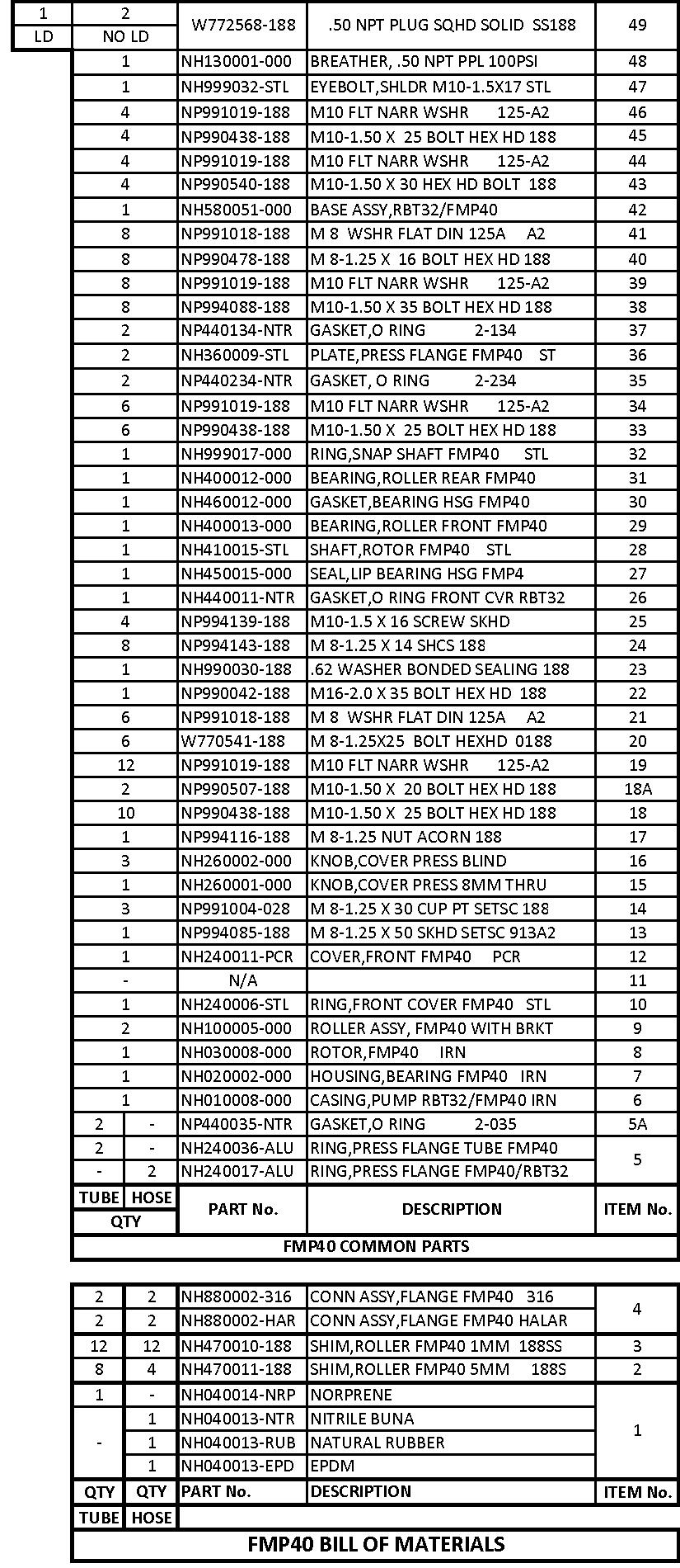
23 20

24 Consult Factory for FMP50 pumps with motor HP Code J 21

25 22
 292-8000")
26 PeriFlo FMP PERISTALTIC PUMP Bulletin #: IOM-PFL-4502 Pulsafeeder, Inc. A unit of IDEX Corporation 2883 Brighton Henrietta Town Line Road Rochester NY (585) pulsa@idexcorp.com
Installation, Operation & Maintenance Manual. Models: ChemTuff Series PeriFlo ChemTuff PERISTALTIC PUMP. IOM-PFL-4600-Rev.B
 Installation, Operation & Maintenance Manual Models: ChemTuff Series 10 22 IOM-PFL-4600-Rev.B PeriFlo ChemTuff PERISTALTIC PUMP Pulsafeeder Factory Service Policy Should you experience a problem with your
Installation, Operation, & Maintenance Instruction. Bulletin #: IOM-PN-LCM D
 Installation, Operation, & Maintenance Instruction Bulletin #: IOM-PN-LCM-0403- D Manufacturers of Quality Pumps, Controls and Systems ENGINEERED PUMP OPERATIONS 2883 Brighton Henrietta Townline Road Rochester,
Installation, Operation & Maintenance Supplement Instruction. Bulletin No.: IOMS-PUL PULSA Series 7120V DRIVE MOTOR INSTALLATION
 Installation, Operation & Maintenance Supplement Instruction Bulletin No.: IOMS-PUL-1012 PULSA Series 7120V DRIVE MOTOR INSTALLATION Copyright 2001-2015 Pulsafeeder, Inc. All rights reserved. ii Conventions
INSTRUCTION MANUAL INDUSTRIAL PERISTALTIC PUMPS MODEL RBT-70
 INSTRUCTION MANUAL INDUSTRIAL PERISTALTIC PUMPS MODEL RBT-70 This manual forms an integral part of the pump and must accompany it until its demolition. The series FMP peristaltic pump is a machine destined
AMP Series. pulsa.com/periflo PERISTALTIC PUMPS. Flow: up to 282 GPM (1067 LPM) Pressure: up to 115 PSI (8 BAR)
 Pressure: up to 115 PSI (8 BAR)") ENGINEERED PRODUCTS Flow: up to 282 GPM (1067 LPM) Pressure: up to 115 PSI (8 BAR) Temperature: Product to 176 F (80 C) Ambient to 104 F (40 C) ChemTuff Series AMP Series FMP Series PeriFlo PERISTALTIC
ENGINEERED PRODUCTS Flow: up to 282 GPM (1067 LPM) Pressure: up to 115 PSI (8 BAR) Temperature: Product to 176 F (80 C) Ambient to 104 F (40 C) ChemTuff Series AMP Series FMP Series PeriFlo PERISTALTIC
Installation Operation Maintenance ADDENDUM
 Installation Operation Maintenance ADDENDUM Bulletin #: PS-IOM-HYPO2-0111-A FACTORY SERVICE POLICY If you are experiencing a problem with your Pulsafeeder pump, first review the IOM, and consult the troubleshooting
DulcoFlex Peristaltic Pump: DFB13B
 INSTRUCTION MANUAL DulcoFlex Peristaltic Pump: This manual forms an integral part of the pump and must accompany it until its demolition. The peristaltic pump is a machine destined to work in industrial
INSTRUCTION MANUAL Rev
 INSTRUCTION MANUAL Rev 12.04.00 PERIFLO PERISTALTIC PUMP MODELS: EQUIPMENT IDENTIFICATION RECORD PUMP MODEL NO: PUMP S/N: CUSTOMER: ORDER NO: JOB NO: TAG NO: HOSE MATERIAL: MOUNTING POSITION: CONFIGURATION:
Installation Operation Maintenance ADDENDUM BULLETIN No. PS-IOM-HYP-0203-H
 Installation Operation Maintenance ADDENDUM BULLETIN No. PS-IOM-HYP-0203-H USER NOTE: This addendum serves as additional information for Pulsafeeder PULSAR and PULSAR Shadow metering pumps equipped with
SERIES PC INSTRUCTION AND OPERATION MANUAL
 MEGGA SERIES PC INSTRUCTION AND OPERATION MANUAL Models PCT and PCF Close-coupled and frame-mounted single-stage horizontal end-suction pumps. WARNING: Read this manual before installing or operating this
Installation, Operation and Maintenance Manual
 Installation, Operation and Maintenance Manual Manual Polymer Makedown Systems Manufacturers of Quality Pumps, Controls, and Systems Standard Product Operations 27101 Airport Rd., Punta Gorda, FL 33982
INSTRUCTION MANUAL GENERAL SAFETY WARNING
 INSTRUCTION MANUAL This manual forms an integral part of the pump and must accompany it until its demolition. The series AMP peristaltic pump is a machine destined to work in industrial areas and as such
Installation, Operation & Maintenance Manual. Models: GLM7 PULSA GLM MECHANICAL DIAPHRAGM METERING PUMP. Bulletin: IOM-GLM-5001-Rev.
 Installation, Operation & Maintenance Manual Models: GLM7 Bulletin: IOM-GLM-5001-Rev.B PULSA GLM MECHANICAL DIAPHRAGM METERING PUMP Pulsafeeder Factory Service Policy Should you experience a problem with
Installation, Operation, & Maintenance Instruction. Model DC7. Bulletin #: IOM-DC C
 Installation, Operation, & Maintenance Instruction Model DC7 Bulletin #: IOM-DC7-0407- C Manufacturers of Quality Pumps, Controls, and Systems STANDARD PUMP OPERATIONS 27101 Airport Road Punta Gorda, FL
Operating instructions Form no safety definitions
 Operating instructions Form no. 1000437 safety definitions safety symbols are used to identify any action or lack of action that can cause personal injury. Your reading and understanding of these safety
DulcoFlex Peristaltic Pump DFC 50
 INSTRUCTION MANUAL DulcoFlex Peristaltic Pump DFC 50 This manual forms an integral part of the pump and must accompany it until its demolition. The peristaltic pump is a machine destined to work in industrial
TWO-STAGE HYDRAULIC PUMP. RWP55-IBT-Air
 ORIGINAL INSTRUCTIONS Form No.1000458 5 SPX Corporation 5885 11th Street Rockford, IL 61109-3699 USA Tech. Services: (800) 477-8326 Fax: (800) 765-8326 Order Entry: (800) 541-1418 Fax: (800) 288-7031 Internet
NECO Pumping Systems
 INSTALLATION OPERATION & MAINTENANCE INSTRUCTIONS For Your NECO Pumping Systems PACKAGED CIRCULATING SYSTEM THIS COMPLETELY ASSEMBLED, TESTED, PACKAGED CIRCULATING SYSTEM IS OF THE HIGHEST QUALITY AND
DulcoFlex Peristaltic Pumps: DFB010 DFB013 DFB016 DFB019 DFB022
 INSTRUCTION MANUAL DulcoFlex Peristaltic Pumps: DFB010 DFB013 DFB016 DFB019 DFB022 This manual forms an integral part of the pump and must accompany it until its demolition. The peristaltic pump is a machine
NECO Pumping Systems
 INSTALLATION OPERATION & MAINTENANCE INSTRUCTIONS For Your NECO Pumping Systems Fuel Oil Transfer System THIS COMPLETELY ASSEMBLED, TESTED, PACKAGED SYSTEM IS OF THE HIGHEST QUALITY AND DESIGN. TO OBTAIN
SELF PRIMING CHEMICAL SERVICE PUMPS
 SELF PRIMING CHEMICAL SERVICE PUMPS INSTALLATION AND OPERATING INSTRUCTIONS This Manual covers: SELF PRIMING MODEL RANGE J50ECX TO J250ECX STAINLESS STEEL*, and NON METALLIC SEAL PUMP MODEL: SERIAL NO:
PLUNGER PUMP SERVICE MANUAL
 PLUNGER PUMP SERVICE MANUAL INSTALLATION AND START-UP INFORMATION Optimum performance of the pump is dependant upon the entire liquid system and will be obtained only with the proper selection, installation
END SUCTION CENTRIFUGAL PUMPS
 OWNERS GUIDE TO INSTALLATION AND OPERATION FW000 009 Supersedes 07 END SUCTION CENTRIFUGAL PUMPS READ THESE INSTRUCTIONS CAREFULLY Read these installation instructions in detail before installing your
BOLT-ON AND WELD-ON FLUSH FLOOR SLIDEOUT SYSTEMS OPERATION AND SERVICE MANUAL
 BOLT-ON AND WELD-ON FLUSH FLOOR SLIDEOUT SYSTEMS OPERATION AND SERVICE MANUAL TABLE OF CONTENTS SYSTEM...... Warning........ Description...... Prior to Operation OPERATION... Main Components... Mechanical...
PLUNGER PUMP SERVICE MANUAL
 PLUNGER PUMP SERVICE MANUAL INSTALLATION AND START-UP INFORMATION Optimum performance of the pump is dependant upon the entire liquid system and will be obtained only with the proper selection, installation
P300 Metering Pump. Installation & Service P A WANNER ENGINEERING, INC.
 P300 Metering Pump Installation & Service P300-991-2400A WANNER ENGINEERING, INC. 1204 Chestnut Avenue, Minneapolis, MN 55403 TEL: (612) 332-5681 FAX: (612) 332-6937 TOLL-FREE FAX [US only]: (800) 332-6812
Installation, Operation & Maintenance Instruction. Models: GLM M1 6 PULSA GLM MECHANICAL DIAPHRAGM METERING PUMP. Bulletin #: IOM-GLM-1303-A
 Installation, Operation & Maintenance Instruction Models: GLM M1 6 Bulletin #: IOM-GLM-1303-A PULSA GLM MECHANICAL DIAPHRAGM METERING PUMP Pulsafeeder Factory Service Policy Pulsafeeder s Factory Service
Crispin Valves Operating Guide. Crispin
 Crispin Valves Operating Guide Crispin Since 1905 Crispin Multiplex Manufacturing Co. 600 Fowler Avenue Berwick, PA 18603 1-800-AIR-VALV T: (570) 752-4524 F: (570) 752-4962 www.crispinvalve.com sales@crispinvalve.com
An Illustrated Manual: Constant Level Lubricators Function, Installation, and Features
 An Illustrated Manual: Constant Level Lubricators Function, Installation, and Features Constant Level Lubricators Table of Contents Overview Typical Applications and Industries..........................
Routine Compressor Maintenance
 Establishing a regular, well-organized maintenance program and strictly following it is critical to maintaining the performance of a compressed air system. One person should be given the responsibility
Installation, Operation & Maintenance Instruction Bulletin #: IOM-NMG-0804 Rev D
 Installation, Operation & Maintenance Instruction Bulletin #: IOM-NMG-0804 Rev D Manufacturers of Quality Pumps, Controls, and Systems ENGINEERED PUMP OPERATIONS 2883 Brighton Henrietta Townline Road Rochester,
1/2" AIR DRIVEN DIAPHRAGM PUMP
 1/2" DRIVEN DIAPHRAGM PUMP OPERATION AND SERVICE GUIDE O-1225D NOV. 2008 Page 1 of 6 Refer to Bulletin P-605, Parts List P-9151 DRIVEN, DOUBLE DIAPHRAGM PUMP MANUAL Congratulations on purchasing one of
LIQUIDYNAMICS Light Viscosity Bulk Transfer Cart
 This manual contains important warnings and information. READ AND KEEP FOR REFERENCE. LIQUIDYNAMICS Light Viscosity Bulk Transfer Cart Instruction & Parts Manual This Manual Covers P/N 33271 P/N 33271
IMPORTANT!!!! Read this manual before attempting any installation, wiring or operation.
 Industrial Turbo Meters Sizes 2" through 6" Installation & Operation Manual IMPORTANT!!!! Read this manual before attempting any installation, wiring or operation. BadgerMeter,Inc. IOM-003-15 Part No.
PO Box 645, Stockton, Missouri, FAX superiorgearbox.com
 I000-7000-D0447-A 4/7/05 1 SAFETY PRECAUTIONS CAUTION Please read this entire document prior to operating the gear drive. Gear drive failure and / or injury to operators may be caused by improper installation,
TITAN FLOW CONTROL, INC.
 PREFACE: This manual contains information concerning the installation, operation, and maintenance of Titan Flow Control (Titan FCI) Wafer Style, Dual Plate Check Valves. To ensure efficient and safe operation
Jet Fans. Instruction Manual READ AND SAVE THESE INSTRUCTIONS WARRANTY
 Jet Fans Instruction Manual READ AND SAVE THESE INSTRUCTIONS WARRANTY All Leader Fan products are guaranteed to be free from defects of workmanship or material and to function satisfactorily when properly
High Frequency SineWave Guardian TM
 High Frequency SineWave Guardian TM 380V 480V INSTALLATION GUIDE FORM: SHF-IG-E REL. January 2018 REV. 002 2018 MTE Corporation High Voltage! Only a qualified electrician can carry out the electrical installation
INSTALLATION OPERATION MAINTENANCE INSTRUCTION
 INSTALLATION OPERATION MAINTENANCE INSTRUCTION BULLETIN No. 680C ENGINEERED PUMP OPERATIONS 2883 Brighton Henrietta TL Road P.O. Box 22909 Rochester, New York, 14692-22909 USA Telephone (716) 292-8000
INSTALLATION, OPERATION AND MAINTENANCE MANUAL (IOM)
") INSTALLATION, OPERATION AND MAINTENANCE MANUAL (IOM) IOM-1088 03-16 Model 1088 Vacu-Gard Blanketing Valve ISO Registered Company SECTION I I. DESCRIPTION AND SCOPE The Model 1088 Vacu-Gard is a tank blanketing
INSTALLATION, OPERATION AND MAINTENANCE MANUAL (IOM) IOM-1088 03-16 Model 1088 Vacu-Gard Blanketing Valve ISO Registered Company SECTION I I. DESCRIPTION AND SCOPE The Model 1088 Vacu-Gard is a tank blanketing
Installation & Operating Manual
 Installation & Operating Manual 25IPCC-M 7/08 Edition PC Series C E N T R I F U G A L Congratulations On Your Choice In Purchasing This Webtrol Pump Its Quality is unsurpassed in material and workmanship
HALLMARK INDUSTRIES INC
 Performance Part No. HP. CONVERTIBLE JET PUMP USER S MANUAL GPH of Water @ Total Discharge Pressure of 40 psi Max. Pressure Max suction (shallow well) Max Suction (deep well) Max GPM (@0 head) Max Discharge
Installation, Operation & Maintenance Manual. Models: E02, E05, E12, E25, E75, E125 ECLIPSE EXTERNAL GEAR METERING PUMP. Bulletin: IOM-ECL-3500-Rev.
 Installation, Operation & Maintenance Manual Models: E02, E05, E12, E25, E75, E125 Bulletin: IOM-ECL-3500-Rev.H ECLIPSE EXTERNAL GEAR METERING PUMP i Pulsafeeder Factory Service Policy Should you experience
OPERATION MANUAL NT50 NOMAD TRANS-FLO AIR-OPERATED DOUBLE DIAPHRAGM PUMPS. A JDA Global Company. 7/11 rev. 1
 OPERATION MANUAL NT50 NOMAD TRANS-FLO AIR-OPERATED DOUBLE DIAPHRAGM PUMPS A JDA Global Company 7/11 rev. 1 CAUTION SAFETY POINTS TEMPERATURE LIMITS: Neoprene -17.8 C to 93.3 C 0 F to 200 F Buna-N -12.2
Maintenance Manual. Automated. Fuel Maintenance System FTI-5A. FUEL TECHNOLOGIES INTERNATIONAL LLC
 Maintenance Manual Automated Fuel Maintenance System FTI-5A FUEL TECHNOLOGIES INTERNATIONAL LLC www.fueltechnologiesinternational.com 03/01/2011 - Fuel Technologies FTI-5A Maintenance Section FTI - Fuel
Industrial Turbo Meters, Sizes 2" through 6"
 Industrial Turbo Meters Sizes 2" through 6" TUR-UM-00530-EN-19 (October 2014) User Manual Industrial Turbo Meters, Sizes 2" through 6" User Manual CONTENTS Scope of the Manual 5 Specifications 5 Product
F-4600 INLINE ULTRASONIC FLOW METER Installation and Operation Guide
 F-4600 INLINE ULTRASONIC FLOW METER Installation and Operation Guide 11451 Belcher Road South, Largo, FL 33773 USA Tel +1 (727) 447-6140 Fax +1 (727) 442-5699 1054-7 / 34405 www.onicon.com sales@onicon.com
ATMOSPHERIC RELIEF VALVE
 IOM-ARV-0814 ATMOSPHERIC RELIEF VALVE INSTALLATION, OPERATION AND MAINTENANCE MANUAL GRAHAM CORPORATION Corporate and Sales Headquarters: 20 Florence Avenue, Batavia, New York 14020 Tel.: 585-343-2216
Series Base mounted pump. Installation and operating instructions
 Series 4030 Installation and File No: 40.80 Date: june 25, 2015 Supersedes: 40.80 Date: october 10, 2009 contents General 4 Inspection 4 Installation - Series 4030 base mounted Pump 4 1.0 Location 4 2.0
UV PROCESS SUPPLY, INC. CON-TROL-CURE
 General Description The CON-TROL-CURE peristaltic pump is self-priming and can handle a wide variety of viscosities (from air to heavy slurries) with positive displacement. The CON-TROL-CURE peristaltic
Embedded Rack Slide-out System
 Embedded Rack Slide-out System SERVICE MANUAL Rev: 02.16.2017 Page 1 Electric Embedded Rack Slide-out System TABLE OF CONTENTS Safety Information 3 Product Information 3 Operation 4 Extending Slide-Out
ROOTS Meters Series B3 Meter Models 8C175-56M175
 ROOTS Meters Series B3 Meter Models 8C175-56M175 Refer to IOM-B3 for Complete Instructions IS:B3 3.03 RECEIVING, HANDLING AND STORAGE ROOTS rotary positive displacement gas meters are precision measurement
Versa-Matic. Operating Manual. 3/8" Bolted Plastic Pumps. Polypropylene Kynar
 Versa-Matic Operating Manual 3/8" Bolted Plastic Pumps Polypropylene Kynar E8 SAFETY WARNINGS Read these instructions completely before installation and start-up. It is the responsibility of the purchaser
To ensure proper installation, digital pictures with contact information to before startup.
 Check List for Optimal Filter Performance? There should be no back-pressure on the flush line. A 1 valve should have a 2 waste line, and 2 valve should have a 3 waste line. Do not use rubber hosing or
Maintenance Manual. Automated Fuel Maintenance System FTI-5A SINGLE TANK FUEL TECHNOLOGIES INTERNATIONAL
 Maintenance Manual Automated Fuel Maintenance System FTI-5A SINGLE TANK FUEL TECHNOLOGIES INTERNATIONAL 05/01/2016 Rev A Fuel Technologies FTI-5A Single Tank Maintenance Section FTI - Fuel Maintenance
BOILER FEED SYSTEM OPERATION AND MAINTENANCE MANUAL
 BOILER FEED SYSTEM OPERATION AND MAINTENANCE MANUAL IMPORTANT These instructions are intended as a guide for the Installing Contractor and as a reference for the Operator, Owner and Serviceman. RETAIN
Bray/ VAAS Slurry Series Knife Gate Valve 760/762/765/766/767/768 Series Operation and Maintenance Manual
 Bray/ VAAS Knife Gate Valve 760/762/765/766/767/768 Series Table of Contents Definition of Terms 1 Safety Instructions 1 Introduction 2 Unpacking 2 Storage 2 Installation 3 Commissioning 3 Cylinder-Operated
Ideal Installation. I & M Mark 67 (1/2 6 ) Control Line. Installation & Maintenance Instructions for Mark 67 Pressure Regulators
 Control Line. Installation & Maintenance Instructions for Mark 67 Pressure Regulators") I & M Mark (/ ) 0 Wasson Road Cincinnati, OH 0 USA Phone --00 Fax -8-00 info@richardsind.com www.jordanvalve.com Installation & Maintenance Instructions for Mark Pressure Regulators Warning: Jordan Valve
I & M Mark (/ ) 0 Wasson Road Cincinnati, OH 0 USA Phone --00 Fax -8-00 info@richardsind.com www.jordanvalve.com Installation & Maintenance Instructions for Mark Pressure Regulators Warning: Jordan Valve
Low Profile J Series Power Unit with Vane Pump
 Low Profile J Series Power Unit with Vane Pump READ ALL INSTRUCTIONS CAREFULLY BEFORE ATTEMPTING TO ASSEMBLE, INSTALL, OPERATE OR MAINTAIN THE PRODUCT DESCRIBED. PROTECT YOURSELF AND OTHERS BY OBSERVING
Operating & Maintenance Manual For Steam Conditioning Valve
 For Steam Conditioning Valve 1 Table of Contents 1.0 Introduction 3 2.0 Product description 3 3.0 Safety Instruction 4 4.0 Installation and Commissioning 5 5.0 Valve Disassembly 6 6.0 Maintenance 6 7.0
PE 20 SERIES ELECTRIC POWER PUMPS
 A Division Of Templeton, Kenly & Co., Inc. PE 20 SERIES ELECTRIC POWER PUMPS Operating Instructions Manual For 1/2 hp, 115 Volt and 230 Volt PEM, PPM, PES and PPS Models Revison B 07/2006 2525 Gardner
VERTICAL MULTI-STAGE CENTRIFUGAL PUMPS
 Installation and Operating Instructions VERTICAL MULTI-STAGE CENTRIFUGAL PUMPS Models 1, 3, 5, 10, 15, 20, 32, 45, 64, 90 1. Model numbering and nameplate format 1.1 Model numbering Example: SBI / SBN
ONYX VALVE CO QUICK START INSTRUCTION. Changing Instruments on an Onyx Isolator Ring
 ONYX VALVE CO QUICK START INSTRUCTION Changing Instruments on an Onyx Isolator Ring CAUTION: The Onyx Isolator ring is vacuum filled with instrument oil. Do NOT loosen or separate any of the pipe fittings,
Maintenance Manual WITH ONE SUBMERSIBLE PUMP. Automated Fuel Maintenance System FTI-5A FUEL TECHNOLOGIES INTERNATIONAL LLC
 Maintenance Manual WITH ONE SUBMERSIBLE PUMP Automated Fuel Maintenance System FTI-5A FUEL TECHNOLOGIES INTERNATIONAL LLC Replacement Manuals Available on Website: www.fueltechnologiesinternational.com
I & M Mark 78 Series. Ideal Installation. Start-Up. Installation & Maintenance Instructions for Mark 78 Control Valves (1-1/2-2 )
") I & M Mark 8 Series 0 Wasson Road Cincinnati, OH 4509 USA Phone 5-5-5600 Fax 5-8-005 info@richardsind.com www.jordanvalve.com Installation & Maintenance Instructions for Mark 8 Control Valves (-/ - ) Warning:
I & M Mark 8 Series 0 Wasson Road Cincinnati, OH 4509 USA Phone 5-5-5600 Fax 5-8-005 info@richardsind.com www.jordanvalve.com Installation & Maintenance Instructions for Mark 8 Control Valves (-/ - ) Warning:
PO Box 645, Stockton, Missouri, FAX superiorgearbox.com W D0446-A 4/1/05 1
 W000-7000-D0446-A 4/1/05 1 SAFETY PRECAUTIONS CAUTION Please read this entire document prior to operating the gear drive. Gear drive failure and / or injury to operators may be caused by improper installation,
300 SERIES 331, 332, 333, 344, 356 AND 367 MODELS
 Section: MOYNO 500 PUMPS Page: 1 of 8 Date: March 1, 1998 SERVICE MANUAL MOYNO 500 PUMPS 300 SERIES 331, 332, 333, 344, 356 AND 367 MODELS Mechanical Seal Models Packing Gland Models MODELS DESIGN FEATURES
of Fire Pump Assemblies
 A.1.0 A.1.1 A.2.0 A.2.1 A.2.2 A.2.3 A.2.4 A.2.5 A.2.6 A.3.0 A.3.1 A.4.0 A.4.1 Report of Inspection, Testing & Maintenance System in service before conducting tasks Pertinent parties notified before conducting
Table 6-1. Problems and solutions with pump operations. No Fluid Delivery
 Table 6-1. and solutions with pump operations No Fluid Delivery Fluid level in the reservoir is low. Oil intake pipe or inlet filter is plugged. Air leak in the inlet line prevents priming or causes noise
HexPro Series Low Profile Wrenches
 HexPro Series Low Profile Wrenches Operation and Maintenance Manual Model 2HP 4HP 8HP 14HP 30HP www.torquetoolsinc.com Use the HEXPRO Series Low Profile Wrenches Model 2HP 4HP 8HP 14HP 30HP to install
DulcoFlex Peristaltic Pump DFDa70
 INSTRUCTION MANUAL DulcoFlex Peristaltic Pump DFDa70 This manual forms an integral part of the pump and must accompany it until its demolition. The peristaltic pump is a machine destined to work in industrial
Premium Series Grease Dispensing Handle One and Two Piece Body Styles
 Service Bulletin SB3018 Rev. A 3/07 Premium Series Grease Dispensing Handle One and Two Piece Body Styles Models: Handle w/swivel and 36" Whip Hose 020 Handle w/swivel and 18" Whip Hose 025 Handle w/swivel
This manual presents installation, servicing, troubleshooting, and maintenance for M PUMPS CM MAG-M SERIES Information that may be required regarding
 Installation, Operating, Maintenance & Safety Instruction for M PUMPS CM MAG-M SERIES Centrifugal light Mag-Drive pumps (CM MAG-M06/1/2/3/4) This manual presents installation, servicing, troubleshooting,
RELEASING PRESSURE IN THE HYDRAULIC SYSTEM,
 Testing And Adjusting Introduction NOTE: For Specifications with illustrations, make reference to SPECIFICATIONS for 225 EXCAVATOR HYDRAULIC SYSTEM, Form No. SENR7734. If the Specifications are not the
SERVICE MANUAL 200 SERIES MOTORIZED 20352, 20452, 20551, 20552, AND MODELS
 Section: MOYNO 500 PUMPS Page:1 of 4 Date: March 1, 1998 SERVICE MANUAL MOYNO 500 PUMPS 200 SERIES MOTORIZED 20352, 20452, 20551, 20552, 22051 AND 22052 MODELS DESIGN FEATURES Housing: AISI 316 stainless
PowerFLO 7800 Series 12 Volt DC Motor-Driven Diaphragm Pumps
 Installation Operation Repair Parts PowerFLO 7800 Series 12 Volt DC Motor-Driven Diaphragm Pumps Specifications Motor Type: 12 VDC, permanent magnet, totally enclosed, non-ventilated Leads: 14 AWG, 12
I & M Mark 78 Series. Ideal Installation. Start-Up. Installation & Maintenance Instructions for Mark 78 Control Valves (1/2-1 )
") I & M Mark 8 Series 30 Wasson Road Cincinnati, OH 4509 USA Phone 53-533-5600 Fax 53-8-005 info@richardsind.com www.jordanvalve.com Installation & Maintenance Instructions for Mark 8 Control Valves (/ -
I & M Mark 8 Series 30 Wasson Road Cincinnati, OH 4509 USA Phone 53-533-5600 Fax 53-8-005 info@richardsind.com www.jordanvalve.com Installation & Maintenance Instructions for Mark 8 Control Valves (/ -
Fisher 657 Diaphragm Actuator Sizes and 87
 Instruction Manual 657 Actuator (30-70 and 87) Fisher 657 Diaphragm Actuator Sizes 30 70 and 87 Contents Introduction... 1 Scope of Manual... 1 Description... 2 Specifications... 2 Installation... 3 Mounting
Operating Manual for Rotary Gear Pumps CMI, S.A. (Mendaro, Guipuzkoa, Spain)
") Operating Manual for Rotary Gear Pumps CMI, S.A. (Mendaro, Guipuzkoa, Spain) Pre-Installation 1. Choose a location that is easily accessible for pump servicing. Ensure adequate electrical service is available.
Operating Manual for Rotary Gear Pumps CMI, S.A. (Mendaro, Guipuzkoa, Spain) Pre-Installation 1. Choose a location that is easily accessible for pump servicing. Ensure adequate electrical service is available.
MAINTENANCE MANUAL FOR THERMOSTATIC TEMPERATURE REGULATING VALVE TRAC STYLE P
 MANUAL NUMBER P-EFS-1 MAINTENANCE MANUAL FOR THERMOSTATIC TEMPERATURE REGULATING VALVE TRAC STYLE P TRAC Regulator Company Inc. 160 South Terrace Avenue Mount Vernon, New York USA 10550-2408 Phone: (914)
M-3025CB-AV Fuel Pump
 SAVE THESE INSTRUCTIONS M-3025CB-AV Fuel Pump Owner s Manual TABLE OF CONTENTS General Information... 2 Safety Instructions... 2 Installation... 3 Operation... 4 Maintenance... 4 Repair... 5 Troubleshooting...
Operating Manual Includes Pumps: PG-9000 Part #R809606
 Operating Manual Includes Pumps: PG-9000 Part #R809606 Introduction Thank you for selecting the PG Series Pumps from Lifegard Aquatics. Before using this pump please take a moment to review this manual.
SAFETY MANUAL READ FIRST!
 966-05-XX SAFETY MANUAL READ FIRST! IMPORTANT: READ THESE WARNINGS AND SAFETY PRECAUTIONS PRIOR TO INSTALLATION OR OPER- ATION. FAILURE TO COMPLY WITH THESE INSTRUC- TIONS COULD RESULT IN PERSONAL INJURY
MUELLER ECCENTRIC PLUG VALVE
 MUELLER INSTALLATION, OPERATING and MAINTENANCE INSTRUCTIONS 1 MUELLER System Design The life of the valve is dependent on its application, frequency of use and freedom from misuse. The properties of the
FTM-L SERIES SINGLE OR TWIN DIRECT STEAM MIXER KETTLE COMPLETE WITH HYDRAULIC POWER TILT BRIDGE PARTS AND SERVICE MANUAL
 FTM-L SERIES SINGLE OR TWIN DIRECT STEAM MIXER KETTLE COMPLETE WITH HYDRAULIC POWER TILT BRIDGE PARTS AND SERVICE MANUAL EFFECTIVE SEPTEMBER 19, 2014 Superseding All Previous Parts Lists. The Company reserves
Installation Operation Maintenance Instruction
 Installation Operation Maintenance Instruction Bulletin #: IOM-NMG-0804 Rev F i ii Pulsafeeder Factory Service Policy Should you experience a problem with your Eclipse Standard/Eclipse Hypo Series pump,
PACKING, HANDLING, TRANSPORTING AND STORING MOTORS
 PACKING, HANDLING, TRANSPORTING AND STORING MOTORS Make sure that the shaft of the motor is not loaded in any way and is protected from knocks. Axial loads or shocks may easily damage the bearings inside
Keystone Series GR resilient seated butterfly valves GRW/GRL Installation and operation manual
 Before installation these instructions must be fully read and understood Important Before valves are installed or used the following actions are recommended. 1. Valves/parts have to be inspected and thoroughly
Purging Air From Divider Block Lubrication Systems
 FROST ENGINEERING SERVICE Purging Air From Lubrication Systems A D I V I S I O N O F G E C S E Y S A L E S & S E R V I C E DESCRIPTION Divider block lubrication systems operate correctly only when all
Low Profile Wrenches Operation and Maintenance Manual
 Low Profile Wrenches Operation and Maintenance Manual http://www.torquetoolsinc.com Use the HEXPRO Series Low Profile Wrenches Model 2HP 4HP 8HP 14HP 30HP to install and remove large bolts that have minimal
INSTRUCTION MANUAL INDUSTRIAL PERISTALTIC PUMPS AMP-22 MODEL
 INSTRUCTION MANUAL INDUSTRIAL PERISTALTIC PUMPS This manual forms an integral part of the pump and must accompany it until its demolition. The series FMP peristaltic pump is a machine destined to work
Installation, Operation, and Maintenance Manual Outdoor Glycol Feed System JWOP /055/100
 Installation, Operation, and Maintenance Manual Outdoor Glycol Feed System JWOP-53-030/055/100 Rev. 1 3/21/11 K.G. Type - John Wood #JWOP-53-030/055/100, Outdoor Glycol Feed System Capacity 30/55/100 Gallons
G2 Optima Plus Flushometer
 3.2.1 For use with Sloan s introduced May, 2003. For older Optima Plus Flushometers (produced from 1992 2003) and Regal Pro Optima Plus Flushometers see pages 3.2.6 thru 3.2.11. SENSOR MODULE COMPONENT
VERTICAL MULTI-STAGES CENTRIFUGAL PUMPS
 Installation and Operating Instructions VERTICAL MULTI-STAGES CENTRIFUGAL PUMPS Models 1, 3, 5, 10, 15, 20, 32, 45, 64, 90, 120, 150 1. Model numbering and nameplate format 1.1 Model numbering Example:
Operation & Maintenance Manual for Northern Magnetic Drive Pumps. Operation Manual. Northern Magnetic Drive 4400 and 4600 Series
 Operation Manual Northern Magnetic Drive 4400 and 4600 Series 340 West Benson Avenue Grantsburg, WI 54840 Telephone: 1-800-366-1410 715-463-5177 www.northern-pump.com Page 1 of 16 Table of Contents Cautionary
Instruction Sheet. 1/2 HP Portable Electric Pumps SAFETY FIRST. L2062 Rev. F 02/ IMPORTANT RECEIVING INSTRUCTIONS 2.
 Instruction Sheet 1/2 HP Portable Electric Pumps L2062 Rev. F 02/12 Index: English:...................................... 1-7 Français:.................................... 8-14 Deutsch:...................................
TITAN FLOW CONTROL, INC.
 PREFACE: TITAN FLOW This manual contains information concerning the installation, operation, and maintenance of Titan Flow Control (Titan FCI)Full Body Swing Check Valves. To ensure efficient and safe
Hydro-Sync Slide-Out System
 Hydro-Sync Slide-Out System SERVICE MANUAL Rev: 08.14.2018 Hydro-Sync Slide-out System Service Manual TABLE OF CONTENTS Safety Information 3 Product Information 3 Operation 4 Extending Slide-Out Room 4
TECHNICAL DATA 1-1/2 (dn40)
") July 1, 2011 Deluge Valves 209a DESCRIPTION The Viking Model E-3 1-1/2 Deluge Valve is a quick-opening, differential type flood valve with a rolling diaphragm clapper. The deluge valve is used to control
July 1, 2011 Deluge Valves 209a DESCRIPTION The Viking Model E-3 1-1/2 Deluge Valve is a quick-opening, differential type flood valve with a rolling diaphragm clapper. The deluge valve is used to control
Penn Valley Pump Company Design Information for Double Disc Pumps
 Penn Valley Pump Company Design Information for Double Disc Pumps INTRODUCTION The Penn Valley Double Disc Pump utilizes a unique principle of operation whereby the discs perform the duties of pumping