RELEASING PRESSURE IN THE HYDRAULIC SYSTEM,
|
|
|
- Jayson Wilfred Rice
- 5 years ago
- Views:
Transcription
1 Testing And Adjusting Introduction NOTE: For Specifications with illustrations, make reference to SPECIFICATIONS for 225 EXCAVATOR HYDRAULIC SYSTEM, Form No. SENR7734. If the Specifications are not the same as in the Systems Operation and the Testing and Adjusting, look at the printing date on the back cover of each book. Use the Specifications given in the book with the latest date. Troubleshooting Hydraulic oil, under pressures that can be higher than kpa (6000 psi) can remain in the hydraulic systems on this machine after the engine and pump have been stopped. Serious injury can be caused if this pressure is not released before any service is done on the hydraulic system. To prevent possible injury, refer to section, RELEASING PRESSURE IN THE HYDRAULIC SYSTEM, before any fitting, hose or component is loosened, tightened, removed or adjusted. When possible, the bucket must always be lowered to the ground before service is started. When it is necessary for the boom to be raised while tests or adjustments are done, be sure that boom and stick have correct support and the bucket is in the full open position. Always move the machine to a location away from the travel of other machines. Be sure that other personnel are not near the machine when the engine is running and tests or adjustments are being made.
2 During a diagnosis of the hydraulic system, remember that correct oil flow and pressure are necessary for correct operation. Pump output (oil flow) is a function of engine speed (rpm). Oil pressure is caused by resistance to the flow of oil. Visual checks and measurements are the first steps when troubleshooting a possible problem. Then do the Operation Checks and last the Instrument Tests. Use the 5S5123 Hydraulic Test Group, a stop watch, a magnet and a mm (inch) ruler for basic tests to measure the following: 1. The opening pressure of the relief valve for the main system and the opening pressure for each of the line relief valves in the individual circuits. Relief valve pressures that are too low will cause an increase in the cycle time of the travel, swing and boom characteristics of the machine. Opening pressures that are too high will cause a decrease in the service life of hoses and components. 2. Drift rates in the boom, stick and bucket circuits. Circuit drift (drifting) is caused by leakage past cylinder pistons, O-rings, check valves or make-up valves that do not seat correctly. Wear or poor fit of spools in the main control valves will also cause drifting. NOTE: If the drifting is in a direction opposite to normal drift, it is a good indication that the leak is on the pressure side of the control valve. In the swing and travel circuits, a ready check of the condition of the motors can be made by an accurate measure of the case drain flow. 3. Cycle times for each of the circuits, boom, stick bucket, swing and travel. Cycle times that are longer than shown in the specifications, (See the 225 HYDRAULIC SYSTEM SPECIFICATIONS, Form No. SENR7734) are the result of leakage, pump wear, pump speed (rpm) or the angle of the swashplate in the pump is not correct. (The control system for the pumps does not have correct adjustment). 4. Pilot system operation. Since the pilot system controls the movement of spools in the main control valves, it is important the pressure and flow of oil from the gear-type pump be according to specifications. The pressure in the pilot system is controlled by the pilot system is controlled by the pilot relief valve. 5. Pump signal pressure (See CHECK OF PUMP CONTROL SYSTEM). Correct pilot pressure does not mean that the signal pressure for control of the pumps is also correct. If the adjustment on the summing valve is not correct, the signal pressure to the pumps will not be according to specifications. If the basic testing gives an indication of circuit leakage, additional testing is necessary. The right track, bucket and boom controls are connected in a series arrangement in the control valve with three stems. The swing, left track and stick controls are connected in a series arrangement in the control valve with five stems. The other two stems in the five stem valve are the boom and stick crossover valves. The boom crossover valve works with the pilot valve for boom control to send rear pump flow to the main control valve for the boom during boom RAISE. The stick crossover valve works with the pilot valve for stick control to send front pump flow to the main control valve for stick during stick (OUT) operation. The three stem valves operate an oil from the front piston pump. The five stem valves operates on oil from the rear piston pump. Each of the circuits has a load check valve to prevent cylinder drift during valve spool movement. Each circuit also has a make-up valve for each end of the cylinders and motors and there is a line relief valve for each of the circuits. Visual Checks
3 A visual inspection of the system is the first step when troubleshooting a problem. Make the inspection with the engine off and the implements lowered to the ground. 1. Check the level of the oil in the hydraulic tank. Slowly loosen the tank filler cap and release the pressure before the cap is removed. 2. Remove the filter element and check it for materials that give an indication of damage to a component. 3. Inspect all lines and connections for damage or leaks. 4. Inspect control linkage for bent, broken or damaged components. Checks During Operation The checks during operation can be used to find leakage in the system. They can also be used to find a valve or pump that is not working correctly. The speed of rod movement or the torque on a motor can be used to check the condition of the cylinders, motors and the pumps. Raise and lower the boom. Move the stick in and out. Open and close the bucket. Move the swing control for swing right and swing left. Do each of these operations several times. 1. Watch the cylinders on the boom, stick and bucket as they are extended and retracted. Movement must be smooth and regular. 2. Listen for noise from the pumps. 3. Listen for the sound of the relief valves when they open. The relief valve for the boom, stick and bucket circuits must open at ± 1030 kpa (3600 ± 150 psi). The relief valve for the swing circuit must not open until the swing circuit pressure reaches ± 1030 kpa (2500 ± 150 psi). NOTE: The relief valve for the track circuit must open at ± 1030 kpa (4000 ± 150 psi). Troubleshooting When troubleshooting a problem in the hydraulic system, keep the basic facts that follow in mind. 1. The main control valves for the right track, bucket and boom are connected in series and make the three stem valve group. They get their supply of oil from the front axial piston pump. Since the three valves are connected in series, the oil flow goes through the track valve first, then the bucket valve, the boom valve and finally through the stick crossover valve. This means that if the track valve is fully open, there is no oil going to the other three valves. Therefore, the bucket and the boom cannot be used when the machine is traveling at full speed. The same is true of the boom and stick crossover when the bucket valve is fully open. The right track still has priority. If the track valve is only open part way, then part of the oil will go to the track and the rest is available to operate the bucket or boom or to send to the stick for two pump operation. The track and the implement will operate at reduced speed under conditions of partial flow. 2. The main control valves for swing, left track, stick and boom crossover are connected in series and make the control valve with five stems. They get their supply of oil from the rear axial piston pump. Like the valve with three stems, the oil flow in the valve with five stems goes through the swing valve first, then the right track valve, the stick valve and finally the boom crossover valve. The swing valve has priority, then the track valve, the stick valve and the boom crossover valve. Their operation is the same as the valve with three stems.
4 3. All eight valves are actuated by pilot pressure from the pilot control valves. The design of the pilot valves is such that it is possible to modulate the main control valves with pilot pressure. 4. Since the track brakes are activated by spring force, it is necessary for the brake valve to release them before the machine can be moved. 5. An increase in load on an implement can cause the piston pumps to decrease their output. This is done by a signal that is sent to both pumps that causes them to "stroke back" (change the angle of the swashplate toward minimum). The signal to the pumps comes from the summing valve when there is an increase in load on an implement. 6. In order to be sure that the correct signal pressure is sent to the piston pumps, the setting of the pressure in the pilot system must be correct. Pilot pressure is adjusted by changing the quantity of shims in the relief valve for the pilot system. When measured at the pressure tap under the cab, the pilot pressure must be 2300 ± 170 kpa (335 ± 25 psi). 7. If there is a problem of power that is common to all operations, check the pump control system. (See CHECK OF PUMP CONTROL SYSTEM). PROBLEM: A reduction in the rpm of the engine (to near stall) when the load on the hydraulic system is increased. This condition can only happen when the piston pumps do not stroke back and there is no reduction in their output. It can be caused by: 1. Low pressure setting in the pilot system. (Check the setting of the relief valve for pilot system pressure). 2. Low horsepower output from the engine. 3. The actuator or servovalve in one or both of the piston pumps has been damaged. 4. The setting of the summing valve is too low. PROBLEM: The time needed (cycle time) to extend or retract all cylinders is more than shown in the specifications. There are several things that can cause this type of problem. 1. The high idle setting of the engine is too low. This will cause a reduction in the output flow of the pumps. NOTE: The full load engine rpm is the speed at which maximum horsepower transfer is available. Full load engine speed (rpm) is changed by adjustment of the high idle setting. 2. The setting for opening pressure of the relief valve in the pilot system is not correct. 3. Both piston pumps are damaged. 4. The swashplates in the implement pumps are at a minimum angle. (See CHECK OF PUMP CONTROL SYSTEM). PROBLEM: The time needed (cycle time) to extend or retract only one cylinder is more than shown in the specifications. The cause for this type of problem will be found in the specific controls of the circuit in which it has happened. 1. Check the linkage between the control lever and the pilot valve. Be sure it is connected correctly and not bent or damaged in any way. 2. There is possible damage to the spool or housing in the main control valve. When this type of problem happens, it usually causes the loss of too much oil. 3. Check the cylinder for damage or leaking piston seals.
5 4. Check the front piston pump if the problem is in the boom or bucket circuits and the rear pump if the problem is in the swing or stick circuits. PROBLEM: with the engine running at full load rpm, there is not enough force or pressure at the implements. 1. The relief valve pressure in the pilot system is too low. This will cause a condition of modulation in the main control valves. There is not enough pilot pressure to move the spools in the main control valves full travel. 2. The setting of the main relief valve is too low. 3. There is possible damage on the inside of the pump(s). It is not possible to get relief valve pressure. (Check the flow from the case drain on the pump). 4. The setting on the summing valve is not correct. PROBLEM: A large amount of air in the oil. 1. A leak in the oil line between the tank and the pump. 2. Failure to correctly bleed the hydraulic system after assembly, inspection or testing. 3. Operation is not correct; relief valve constantly opens and closes. 4. Leakage in and around cylinder seals. PROBLEM: Pumps are too noisy. Noise from the area where the pumps are located may not be coming from the pumps. When trying to find the cause of noise in this area, be sure to check the pump drive. Noise from the pump drive will follow the connecting shaft and housings and make it seem as through the noise is in the pump. 1. If all the pumps are found to be noisy, there is probably air in the oil (oil aeration). 2. If the noise is found to be in only one pump, it is probably caused by wear or damage to that pump. PROBLEM: Hydraulic oil temperature is too high. Oil temperature that is too high can be caused by many things. The removal of baffles in the control compartment can let hot air move across the pumps and cooler. Operation of the machine with one or more relief valves open longer than necessary. In addition, there can be: 1. Oil aeration (air mixed with the oil). 2. A restriction to the flow of cool air through the oil cooler. Ambient (outside) air temperature too high. 3. A restriction that would keep the heat from the cooler from going into the surface air. 4. A restriction to the flow of oil through the cooler because the cooler flow control valve is being held open. PROBLEM: Hydraulic oil temperature is too low. Low oil temperature can cause many problems. It can also be the cause of symptoms of other problems. The temperature of the oil must be such that it flows through the lines and components freely. Low oil temperature can be caused by: 1. The cooler flow control valve lets too much oil flow go to the cooler. 2. The cooler, tank and other hydraulic components do not have enough protection from low outside temperature and/or winds. PROBLEM: The modulation of all the implements is not normal.
6 The only part of the hydraulic system that is common to all implements is the pilot circuit. A defect in the pilot system can keep the engine from working correctly, cause surging in the implement circuits and prevent the correct operation of the piston pumps. Some of the causes of pilot system problems are: 1. Leakage in the system that prevents the pressure from going to 2300 ± 170 kpa (335 ± 25 psi). 2. The temperature of the oil is too low. 3. The opening pressure of the relief valve in the pilot system is too low. 4. Oil aeration (air mixed with the oil). 5. The pilot pump has been damaged or has too much wear. PROBLEM: The modulation of one implement is not normal. When the problem happens in only one circuit, the cause can usually be found in a component that is common to that circuit only. 1. The linkage to the spool in the pilot valve that controls the implement is out of adjustment, bent or not connected. 2. If the main control valve for the implements has just been assembled after repair, it is possible that there is air in the cover over the end of the spool. (See PROCEDURE TO REMOVE AIR FROM THE PILOT SYSTEM). 3. The spool in the main control valve does not move freely. PROBLEM: The machine will not move when FORWARD or REVERSE pedals are pushed down. Components in the track circuits are the front and rear piston pumps (one pump for each track motor), main relief valve, line relief valves, swivel, motors, (one for each track), make-up valves, main control valves, pilot control valves, overspeed valves and the overspeed damping orifice. The only components that are common to both track motors are the main relief valve and the swivel. In addition, the track brake valve in the pilot system is common to both tracks (a signal pressure from the track brake valve must release the brakes before the machine can be moved). Make the checks that follow if the machine will not move in either direction: 1. Pressure in the pilot system must be higher than 1790 kpa (260 psi) before the track brakes will release. 2. The safety lever is in the SAFE position. 3. The stop has been turned in on the track brake valve and signal pressure can not release the track brakes. 4. There is dirt in the track brake valve. 5. There is a bad seal in the brake line part of the swivel. 6. There is an object keeping the tracks from turning. 7. The dampening orifice is not plugged. PROBLEM: The machine will move but has no steering. The only component that can have a defect in this problem is the steering valve and linkage. Check the linkage between the steering lever and steering valve. Be sure that it is adjusted correctly and not bent, broken or disconnected. If there is no problem with the linkage, check inside the steering valve to be sure the lever is connected. PROBLEM: Too much drift in one of the hydraulic cylinders. Leakage, in or around a component, is normally the cause of cylinder drift. In the stick and bucket circuits are the main control valves, line relief valves, make-up valves and cylinders. In the boom circuit, in addition to the same components used in the other two circuits, there is the boom vent valve, and the boom check and relief valve. Following are some of the causes of drifting to be found in these circuits:
7 1. Leakage in and around the seals on the pistons in the cylinders. 2. Leakage past a line relief valve or make-up valve in the main control valve for the circuit with drift. 3. The spool in the main control valve is not correctly centered. This problem can be caused by a broken spring or sticky valve spool. 4. There is a small amount of pilot pressure at the end of the spool in the main control valve. This causes the spool to be off-center and leakage will let the cylinder drift. (Check the pilot control valve). 5. If the drift problem is in the boom cylinders, the cause can be any of those above. In addition, the cause can be in the boom vent valve or the boom check and relief valve. PROBLEM: The boom will not raise or lower, but all of the other implements operate correctly. The same components that cause cylinder drift will also cause this problem. 1. The spool in the boom vent valve is stuck. This will cause the boom check valve to be blocked and will not let head end oil go out of the cylinder for boom LOWER. 2. There is no movement by the spool in the main control valve. This can be caused by a defect in the spool or body of the valve. 3. Control linkage between the lever and pilot valve for the boom is disconnected, bent or out of adjustment. PROBLEM: The oil level in the compartment of the final drive is too high. 1. Too much oil has been added to the compartment. 2. There is oil leakage from the track motor. 3. There is oil leakage from the track brake. PROBLEM: The oil level in the compartment of the pump drive is too high. 1. There has been too much oil added to the compartment. 2. Leakage from one or both of the piston pumps. It is possible for oil to get past the seals in the pump. PROBLEM: When the control valve for the boom or stick is activated, the implement (boom or stick) moves with a surge. 1. The summing valve is not working correctly. 2. There has been a change in the horsepower output of the engine. 3. The line from the summing valve to the pumps is not open. PROBLEM: Line relief valves are noisy. 1. The setting of the relief valve is too low. 2. The setting of the main relief valve is too high. Testing And Adjusting Machine Performance Checks An analysis of the engine rpm during specific load conditions is an important aid in troubleshooting problems. For the tests that follow, put the governor control at its maximum setting.
8 Analysis NOTE: The engine rpm information given is to be used as a guide only. As will be seen later, the actual rpm may vary between machines. In an analysis of machine performance, comparison of engine rpms under different conditions of loading is of very little value. There are conditions however, when a change in engine rpm can be an indication of the cause of a problem. 1. Pilot pressure must always be according to specifications. If the pilot pressure is less than specifications, it will not be possible to get maximum signal from the summing valve to the pump servovalves. This means that the pumps would not stroke back (change angle) to minimum displacement. Under this condition the engine rpm will go below full load rpm whenever it is loaded. 2. Axial piston pump displacement must always be the same. Output from the pumps must always be the same for each pump. This means that the signal pressure to each of the pumps must be the same. Servovalve adjustment must be such that output from one pump is the same as from the other. If the signal to each pump is the same, then the cause for the difference in output is probably a difference in the setting of the maximum angle stops. This can be seen in a difference in rpm between Tests 2 and 3. It will also make a difference in Test 4. Use the cycle times to check on the flow from the pumps. 3. Maximum machine performance and efficiency are possible only when there is a balance between horsepower needed to do the job and horsepower available from the engine. If both of the axial piston pumps were operated under conditions of maximum flow (output) and pressure, the horsepower needed would be approximately 2.3 times the amount available from the engine. If some way to control the load on the engine was not installed on the machine, the engine would lug to a stop. The pump control system is designed to keep an exact relationship between engine rpm, pump discharge pressure and pump flow output (swashplate angle) times. Make reference to WARNING on first page of EXCAVATOR HYDRAULIC SYSTEM TESTING AND ADJUSTING section. Use high pressure testing equipment only. Pressure can be more than kpa (4500 psi).


9 Adjustment Of Relief Valve In Main System Oil PRESSURE TAPS FOR PRESSURE OF MAIN SYSTEM 1. Location of pressure tap for circuits of rear pump supply. 2. Location of pressure tap for circuits of front pump supply. Use Steps 1 through 9 to check and make adjustment of the opening pressure of the relief valve in the main system oil. RELIEF VALVE FOR MAIN SYSTEM OIL 3. Relief valve. 1. Install pressure gauge in location (1) and/or (2). 2. Screw the plunger in on the track brake valve until the spool is blocked. 3. Start the engine. 4. Move the hand lever for control of stick movement to the STICK OUT or IN position and hold it there after the stick cylinder is either fully extended or retracted. The oil pressure at location (1) must be ± 1030 kpa (3600 ± 150 psi). 5. Move the hand lever for control of boom movement to the BOOM RAISE or LOWER position and hold it there after the boom cylinders are either fully extended or retracted. The oil pressure at location (2) must be ± 1030 kpa (3600 ± 150 psi).
 and (2) are less than 23 700 kpa (3450 psi) or more than 25 800 kpa (3750 psi), remove cover (7) and add/or remove shims (8). Each 0.12 mm (.005 in.")
10 CROSS-SECTION OF THE TRACK BRAKE VALVE 4. Plunger. 6. If the oil pressures at locations (1) and (2) are not the same, make an inspection of the check valves in the combiner valve. If the oil pressures at locations (1) and (2) are less than kpa (3450 psi) or more than kpa (3750 psi), remove cover (7) and add/or remove shims (8). Each 0.12 mm (.005 in.) shim will change the opening pressure approximately 310 kpa (45 psi). Add shims for a higher opening pressure and remove shims for a lower opening pressure. 7. Push down on either of the foot pedals for machine travel. The oil pressure at locations (1) and (2) must be ± 1030 kpa (4000 ± 150 psi). 8. If the pressure is less than kpa (3850 psi) or more than kpa (4150 psi), add or remove shims (8). 9. Unscrew the plunger in the track brake valve until the spool operates normally. Adjustment And Check Of Line Relief Valves
11 COMBINER AND MAIN RELIEF 5. Plug. 6. Spool. 7. Cover. 8. Shims. Make reference to WARNING on first page of the TESTING AND ADJUSTING section. Extreme caution must be used when testing the line relief valves. These valves are set to open at kpa (4800 psi) except the track circuits which are set to open at kpa (5500 psi). Under conditions of tolerance build-up these pressures can exceed kpa (6200 psi). The procedure that follows is to be used only if it is absolutely necessary. When testing the line relief valves, spool (6) must be put in its reverse position. Remove plug (5) and spool (6). Install spool (6) end for end (reverse position to that shown) and install the plug. This stops the oil flow to the pilot valve. The oil pressure in each circuit is now limited by the line relief valve in that circuit. 1. Move the hand lever for control of boom movement to the BOOM RAISE position and hold it there after the boom cylinders are fully extended. The oil pressure at location (2) must be ± 1380 kpa (4800 ± 200 psi), the opening pressure of the line relief valve in the boom check and relief valve. If it is necessary to test the line relief valve for boom LOWER, remove it and install it in one of the other circuits. DO NOT USE THE BOOM LOWER CIRCUIT FOR TESTING. The opening pressure must be ± 1380 kpa (4800 ± 200 psi).
 shows the opening pressure of the line relief valve in the outer end of the bucket control valve. The opening pressure must be 33 000 ± 1380 kpa (4800 ± 200 psi).")
12 2. Move the hand lever for control of bucket movement to the BUCKET OPEN position and hold it there after the bucket cylinder is fully retracted. The oil pressure at location (2) shows the opening pressure of the line relief valve in the outer end of the bucket control valve. The opening pressure must be ± 1380 kpa (4800 ± 200 psi). Move the hand lever for control of bucket movement to the BUCKET CLOSE position and hold it there after the bucket cylinder is fully extended. The oil pressure at location (2) shows the opening pressure of the line relief valve in the inner end of the bucket control valve. The opening pressure must be ± 1380 kpa (4800 ± 200 psi). 3. Screw plunger (4) in on the track brake valve until the brake valve spool is blocked. 4. Push down on the pedal for FORWARD travel and hold it down. Move the hand lever for control of steering to full STEER LEFT position and hold it in that position. The oil pressure at location (2) shows the opening pressure of the line relief valve on the outer end of the control valve for movement of the right track. The oil pressure at location (1) shows the opening pressure of the line relief valve at the inner end of the control valve for the movement of the left track. 5. Push down on the pedal for REVERSE travel and hold it down. Move the hand lever for control of steering to full STEER RIGHT position and hold it in that position. The oil pressure at location (2) shows the opening pressure of the line relief valve on the inner end of the control valve for movement of the right track. The oil pressure at location (1) shows the opening pressure of the line relief valve at the outer end of the control valve for the movement of the left track. The opening pressure of all line relief valves tested in Steps 3 and 4 must be ± 1380 kpa (5500 ± 200 psi). 6. Unscrew the plunger in the track brake valve until the brake valve spool operates normally. 7. Move the hand lever for control of stick movement to the STICK OUT position until the stick cylinder is fully retracted and hold. The oil pressue at location (1) shows the opening pressure of the line relief valve at the outer end of the stick control valve. Move the hand lever for control of stick movement to the STICK IN position until the stick cylinder is fully extended and hold. The oil pressure at location (1) shows the opening oil pressure of the line relief valve at the inner end of the stick control valve. The opening pressure of the line relief valves must be ± 1380 kpa (4800 ± 200 psi). NOTE: Drop the swing lock pin into the LOCKED position. 8. Move the hand lever for control of swing movement to the SWING RIGHT position and hold. The oil pressure at location (1) shows the opening pressure of the line relief valve for swing RIGHT. Move the hand lever for control of swing movement to the SWING LEFT position and hold. The oil pressure at location (1) shows the opening pressure of the line relief valve for swing LEFT. The opening pressure of the line relief valves must be ± 1030 kpa (2550 ± 150 psi).
 will change the opening pressure of the line relief valve 785 kpa (114 psi) in all cases except the swing.")
13 LINE RELIEF VALVE (Example shown is from the line relief for swing) 9. Shims. All line relief valves are the same except for the number of shims (9). One of the shims (9) will change the opening pressure of the line relief valve 785 kpa (114 psi) in all cases except the swing. One shim in the line relief for swing will change the opening pressure 840 kpa (122 psi). Adjustment Of Relief Valve In Pilot System Use steps 1 through 4 to check and make adjustment of the relief valve in the pilot system. 1. Install pressure gauge at location (1). 2. With the engine running between 1000 rpm and high idle, the pressure at (1) must be 2300 ± 170 kpa (335 ± 25 psi). TEST LOCATION FOR PRESSURE OF PILOT SYSTEM 1. Location for pressure gauge.
. 4. If gauge indication is more than 2470 kpa (360 psi), remove cover (3) and remove from shims (4).")

14 CROSS-SECTION OF RELIEF VALVE 3. Cover. 4. Shims. RELIEF VALVE FOR PILOT SYSTEM 2. Relief valve. 3. If gauge indication is less than 2120 kpa (310 psi), remove cover (3) and add to shims (4). Each shim changes the opening pressure approximately 129 kpa (18.5 psi). 4. If gauge indication is more than 2470 kpa (360 psi), remove cover (3) and remove from shims (4). Testing The Control Valves For Speed And Direction Valves (1) and (3) give modulation for the rate of oil flow to the track motors. (See SPEED AND DIRECTION CONTROL in SYSTEMS OPERATION). Use the steps that follow to test the outlet pressures to the control valves for oil flow to the track motors. 1. Screw the plunger in on the track brake valve until the spool is blocked. CONTROL VALVE FOR SPEED AND DIRECTION 1. Valve for control of movement in the REVERSE direction. 2. Valve for control of steering. 3. Valve for control of movement in the FORWARD direction.
")
15 CROSS-SECTION OF CONTROL VALVE FOR SPEED AND DIRECTION 4. Plunger. 5. Plunger. 6. Shims. 7. Shims. 2. Install pressure gauges in the covers on the ends of the stems of the main control valves for track movement. 3. With the engine running, push plunger (4) of valve (1) down 7.9 mm (5/16 in.). The pressure at the inner (tang) end of the stems of the control valves for right track and left track movement must be 1200 ± 28 kpa (175 ± 4 psi). If the pressures are not the same, check the oil lines to the control valves for restriction. If the pilot pressure to the control valves is less than 1175 kpa (171 psi) or more than 1228 kpa (179 psi), make an adjustment by adding or removing shims (6). Each 0.13 mm (.005 in.) shim will change the pressure of the pilot oil to the control valves 12 kpa (1.7 psi). Add shims to increase the pressure. Remove shims to decrease the pressure. When plunger (4) is pushed down to its full travel, the oil pressure to the control valve must be 2300 ± 170 kpa (335 ± 25 psi). 4. Do Step 3 again and use plunger (5), in valve (3), for oil pressure to the outer (spring) end of the stems of the control valves for right track and left track control. Use shims (7) to make adjustment of oil pressure. 5. With plunger (4) pushed down to its full travel, move the hand lever for control of steering to the left, one half the distance of its full travel. The pressure of the oil to both ends of the spool for left track movement and the outer end of the spool for right track movement must be approximately 2300 kpa (335 psi). Move the lever for steering control to the left to the limit of its full travel. The pressure of the oil to the inner end of the spool for left track movement and the outer end of the spool for right track movement must be approximately 2300 kpa (335 psi). 6. With plunger (5) pushed down to its full travel, move the hand lever for control of steering to the right, one half the distance of its full travel. The pressure of the oil to both ends of the spool for right track

16 movement will be near zero and the pressure of the oil to the inner end of the spool for left track movement will be approximately 2300 kpa (335 psi). Move the lever for steering control to the right to the limit of its travel. The pressure of the oil to the outer end of the spool for right track movement and the inner end of the spool for left track movement must be approximately 2300 kpa (335 psi). 7. Unscrew the plunger in the track brake valve until the spool operates normally. Flushing Procedure See Special Instruction, SMHS6936, PROCEDURE TO FLUSH AND CLEAN EXCAVATOR HYDRAULIC SYSTEMS. Test Of A New Machine For Correct Pump Control Adjustments 1. Connect the positive lead from the 6V3030 Multimeter to the 12 volt terminal of the 24 volt battery group. 2. Set the multimeter on the 20 volt scale. 3. Touch the negative lead from the multimeter to the machine frame. The meter must read 12 to 14 volts. 4. Connect the negative lead from the multimeter to the brass terminal post on the governor. 5. Start the engine and pull the governor control lever into the HI IDLE position. 6. Get the temperature of the oil to 49 to 71 C (120 to 160 F). 7. Move the safety lever to the OPERATE position. Move the bucket to the CLOSED position (bucket cylinder fully extended). Move the stick to the OUT position (stick cylinder fully retracted). 8. Slowly, and at the same time, move the stick control lever to the OUT position and the bucket control lever to the CLOSED position. There must not be a voltage reading on the multimeter. 9. If there was no voltage reading on the multimeter, remove the multimeter. The machine has the correct adjustments. 10. If there was a voltage reading on the multimeter, do the following procedure. Adjustment Procedure For the Pump Control System SUMMING VALVE 1. Summing valve.
 (part of the main relief-combiner valve group) and the servovalves (2) (one in each of the implement")
17 SERVOVALVES 2. Servovalves (two). There are three valves used in the adjustment of the pump control system: the summing valve (1) (part of the main relief-combiner valve group) and the servovalves (2) (one in each of the implement pumps). The summing valve sends a signal to the pumps (servovalves) whenever there is a load on one or more of the implements. The amount of signal pressure increases as the load increases. Both the summing valve and the servovalves are adjustable. The procedure that follows will give the correct setting for each of these valves. This will then give the correct hydraulic horsepower for operation of the machine. The procedure must be used whenever there is a change in engine horsepower or when a new summing valve or pumps has been installed. NOTE: All tests made on the pump control system must be made with accurate gauges. Heat the hydraulic system until the oil is 54 to 65 C (130 to 150 F). it may be necessary to stop the flow of air through the cooler in order to get the correct temperature for testing. Adjustment of Pump Controls 6V3079 Hose Assembly. * 6V4142 Nipple. * 6V4143 Coupler. * 6V3030 Multimeter.FT1612 Wrench.2-25 foot long - 22 gauge wire with small clips.2-5p7336 Bolts (9/16-18 thread) mm (18.4 in.) long. * Use pipe sealer and put these items together. Adjustment Procedure 1. Put the machine on a level surface. Swing the boom around until it is over the track motors. Put the swing pin in the LOCKED position. 2. Raise the boom, put the stick in full out position and the bucket in fully closed position. 3. Lower the boom until the bucket is on the ground. 4. Put the safety valve in the SAFE position and leave it in this position for the rest of the test. 5. Stop the engine. 6. Check the level of the hydraulic oil in the tank. It must be above the ADD mark. Installation of Tools and Preparation of the Machine

. Then push it forward (shut off). 8.")
18 VOLTMETER CONNECTION AND TEST Connection point for 12 volts 1. Connect the positive lead from the multimeter to a 12 volt terminal of the 24 volt battery group. NOTE: Use one of the 25 foot wires. 2. Set the voltmeter on the 20 volt scale. 3. Turn the machine disconnect switch ON. 4. Touch the negative lead from the voltmeter to the machine frame. The meter must read 12 to 14 volts. 5. Use the second 25 foot wire and connect the negative lead from the voltmeter to the brass terminal post on the governor. CONNECTION OF BRASS TERMINAL ON GOVERNOR 6. DO NOT START THE ENGINE. 7. Pull the governor control lever to the rear (wide open). Then push it forward (shut off). 8. Multimeter must read 12 to 14 volts with governor control wide open and zero with the governor control closed. NOTE: If the multimeter reads full scale when the governor control is in the shut off position, hit the governor housing lightly. This will loosen the pin and lever inside the housing. If it does not, it will be necessary to remove the housing cover and push the contractor pin down. The pin can be cleaned with steel wool or fine grit emery paper.
. 9. Connect a 52 000 kpa (7500 psi) pressure gauge in the pressure tap for the rear pump. 10.")


19 LOCATION FOR CONNECTION OF PRESSURE GAUGE PLUGS IN END HOUSINGS FOR STICK AND STICK CROSSOVER VALVES 1. Plug (stick crossover). 2. Plug (stick). 9. Connect a kpa (7500 psi) pressure gauge in the pressure tap for the rear pump. 10. Remove plugs (1) and (2) from the end housings for the main control valves for stick and stick crossover. 5P7336 BOLTS INSTALLED IN END HOUSINGS 11. Install a 5P7336 bolt in each of the end housings. 12. Turn each of the bolts in until they touch the end of the valve spools. 13. Start the engine and pull the governor control lever to full open. Turn the bolt on the stick control valve in (clockwise) until the valve spool stops. The pressure gauge must read ± 1030 kpa (3600 ± 150 psi). Turn the bolt out until the pressure gauge reads 1200 kpa (175 psi) or less. Stop the engine.
, check the accuracy of the gauge or change shims in the main relief valve and do Step 13 again. 14.")
 to prevent a change in adjustment due to engine vibration. CAPS OVER SERVOVALVE ADJUSTMENT SCREWS 16. Remove the caps from the adjustment screws on the servovalves. 17.")
20 SUMMING VALVE 3. Cap. 4. Locknut. NOTE: Use the long hose assembly, coupler and nipple from the tool list to bring pressure gauge to the other side of the machine. NOTE: If the pressure gauge did not read ± 1030 kpa (3600 ± 150 psi), check the accuracy of the gauge or change shims in the main relief valve and do Step 13 again. 14. Remove cap (3) and loosen locknut (4) on the summing valve. 15. Use a 1/4 in. hex wrench and turn the adjustment screw out (counterclockwise) 4 or 5 turns. Tighten locknut (4) to prevent a change in adjustment due to engine vibration. CAPS OVER SERVOVALVE ADJUSTMENT SCREWS 16. Remove the caps from the adjustment screws on the servovalves. 17. Use a 3/16 in. hex wrench and turn the adjustment screw out (counterclockwise) until the screw is against the stop. Always lock the adjustment screws to prevent changes due to engine vibrations. NOTE: Shut the engine off. 18. Disconnect signal line (5) from the tee under the front pump (6). Put a 9S5518 Plug in the line. Do not put a cap on the tee. Leave the servovalve port open to atmosphere.

21 SIGNAL LINE TO PUMPS 5. Signal line. 6. Front axial piston pump. NOTE: A very small amount of oil will be lost from the open line. A large amount is an indication of a leaky seal in one of the servovalves. 19. Start the engine and pull the governor control lever full open. 20. Get the temperature of the hydraulic oil to 49 to 71 C (120 to 160 F). NOTE: Temperature gauge on instrument panel must be 1/4 to 1/2 into green temperature band. Oil can be heated by turning the bolt on the stick control valve in (clockwise) until the pressure gauge reads between and kpa (2500 and 3000 psi). 21. If used, remove the cardboard in front of the cooler after the gauge indicator is 1/4 into the green band. Keep the governor control wide open and the temperature constant for the rest of the test. Turn the bolt on the stick valve out (counterclockwise) when the oil reaches the desired temperature. Finding the Balance Point of the Engine 22. Turn the bolt on the stick control valve in slowly until the voltmeter reads between 1.0 and 2.0 volts. Write this pressure down. This is the balance point pressure. Turn the bolt out until the pressure gauge reads less than 1200 kpa (175 psi). 23. Stop the engine. NOTE: If the stick control valve comes up against the stop (main relief valve pressure will be read on the gauge) before a 1.0 to 2.0 volt reading is obtained in the voltmeter, it is an indication of one or more of the following problems. a. Power setting on the engine is too high. NOTE: This will result in fuel consumption that is too high. b. Maximum swashplate angle, in the rear pump, is out of adjustment. c. Pressure gauge in use is not accurate. The problem(s) must be taken care of, if possible. If it is not possible, write down a balance point pressure of kpa (3250 psi) or more. If the balance point pressure is kpa (2700 psi) or higher, connect the signal line back to the tee on the front pump and go to Step 24.
22 If the balance point pressure is less than kpa (2700 psi) check for one or more of the following causes: a. Machine is working at an altitude above 2286 m (7500 ft.). b. Machine has one or more hydraulic attachments that get their oil from an auxiliary pump or from the standard hydraulic circuit. (Power beyond from one of the main control valves). c. Engine has been equipped with many attachments, (for example, an auxiliary electric power generator, an air compressor, etc). d. Machine is being used in areas of extreme temperatures of heat [above 38 C (100 F)] or cold [below - 18 C (0 F)]. NOTE: When the outside (ambient) temperature is very cold it will be necessary to run the engine until the hydraulic oil gets warm. If any of these conditions are applicable, connect the signal line to the tee at the front axial piston pump and go to Step 24. If none of these conditions are applicable, a balance point pressure that is less than kpa (2700 psi) may be an indication of one of the following. a. Fuel API is not correct. b. Low engine power setting. c. Fuel lines have air in them. d. Governor linkage is not free to move. e. High idle setting on the engine is not correct. f. Pressure gauge is not accurate. g. Other engine problems. h. Bearings in pump drive are too tight. The problem(s) must be taken care of, if possible. If it is not possible, the machine can be set so that the engine does not lug and work can be done until it is possible to get the problem(s) fixed. The power settings that are obtained under these conditions can result in slower machine movement and longer cycle times. Connect the signal line to the tee at the front pump and proceed as follows. Adjustment of Summing Valve Signal Pressure 24. If the balance point pressure is less than kpa (3250 psi) go to Step If the balance point pressure is 3250 psi or higher, put pilot pressure to the main relief valve where the line from the track brake valve enters. This can be done by connecting a line between the tee tap for the pilot system and the line from the track brake valve and the main relief valve. Put a tee and line (from the 5P5224 Pressure Gauge Kit) on the tee tap for the pilot system. Disconnect the line between the track brake valve and the main relief valve at the track brake valve. Install the coupler and nipple (from the tool list) in the line to the main relief valve. Connect the two lines together. Put a cap on the track brake valve where the line was removed. Take the line from the top of the filter around the front of the hydraulic tank away from the engine.
23 26. Start the engine and pull the governor control lever fully open. 27. Turn the bolt on the stick valve in (clockwise) until the spool is against the stop. The pressure gauge must read ± 1030 kpa (4200 ± 150 psi) [ ± 1030 kpa (4000 ± 150 psi) on machines with serial numbers 76U U1648]. 28. Turn the bolt on the stick control valve out (counterclockwise) until the pressure gauge reads 1200 kpa (175 psi) or less. 29. Stop the engine. NOTE: Make adjustments to the main relief valve for the tracks, if necessary, and do Step 27 again. 30. Start the engine and pull the governor control lever fully open. 31. Turn the bolt on the stick valve in (clockwise) until the spool is against the stop. 32. Take the voltmeter under the machine and turn the adjustment screw on the summing valve in (clockwise) until the voltmeter reads 1.0 to 2.0 volts. Lock the adjustment screw after adjustment is complete. 33. Turn the bolt on the stick valve out (counterclockwise) until the pressure gauge reads 1200 kpa (175 psi) or less. 34. Check the temperature of the hydraulic oil to make sure that it is not too hot [needle 3/4 (or more) of the way into the green band]. If the oil is too hot, let the engine run at half throttle (all controls in neutral) until the oil temperature is down to the desired range, (1/4 to 1/2 of the way into the green temperature band). Pump Servovalve Spring Adjustments 35. Pull the governor control lever fully open. 36. Turn the bolt on the stick valve in (clockwise) until the spool is against the stop. Write down the reading on the voltmeter. 37. Take the voltmeter around to the rear axial piston pump and turn the servovalve adjustment screw in (clockwise) until the voltmeter reads 1.0 to 2.0 volts more than the voltage read in Step 36. Lock the adjustment screw. 38. Turn the bolt on the stick valve out (counterclockwise) until the pressure gauge reads 1200 kpa (175 psi) or less. Check the temperature of the hydraulic oil to make sure that it is not too hot. (See Step 34). 39. Pull the governor control lever fully open. 40. Turn the bolt on the stick crossover valve in (clockwise) until the spool is against the stop. Write down the reading on the voltmeter. NOTE: The value of this reading can be 0 volts. 41. Take the voltmeter around to the front axial piston pump and turn the servovalve adjustment screw in (clockwise) until the voltmeter reads 1.0 to 2.0 volts more than the voltage reading in Step 40. Lock the adjustment screw. 42. Turn the bolt on the stick crossover valve out (counterclockwise) until the bolt no longer touches the spool.
24 Final Adjustment of the Summing Valve and Pump Servovalves 43. If the balance point pressure is kpa (3250 psi) or less use ± 690 kpa (1600 ± 100 psi) pressue to load the rear pump in Steps 48 and 49. Go to Step If the balance point pressure is 3250 psi or more, stop the engine and disconnect the pilot pressure line that was installed between the tee tap for the pilot system and the main relief valve. Connect the line between the track brake valve and the main relief valve. 45. Turn the adjustment screw on the summing valve out (counterclockwise) 1/2 turn. 46. Turn the front and rear pump servovalve screws out (counterclockwise) one turn each to keep the engine from lugging too much during the following steps. Lock the adjustment screw. 47. Start the engine and pull the governor control lever fully open. Check the temperature of the hydraulic oil to make sure that it is not too high. 48. Turn the bolt on the stick crossover valve in (clockwise) until the spool is against the stop. 49. Turn the bolt on the stick valve in (clockwise) until the pressure gauge reads ± 690 kpa (2300 ± 100 psi). 50. Take the voltmeter and the pressure gauge around to the front and rear axial piston pumps. Turn the servovalve adjustment screw on each pump out (counterclockwise) an equal amount of turns until the voltmeter reads 1.0 to 2.0 volts. Keep the pressure on the rear pump (bolt in the stick valve) adjusted to the correct load pressure while the servovalves are being adjusted. Lock the adjustment screws. 51. Turn the bolt on the stick valve out (counterclockwise) until the bolt no longer touches the spool. The pressure gauge must read less than 1200 kpa (175 psi). 52. Turn the bolt on the stick crossover valve out (counterclockwise) until the bolt no longer touches the spool. 53. Stop the engine. 54. Turn the servovalve adjustment screws on each of the pumps out (counterclockwise) an equal number of turns, as shown in the chart below. 55. Turn the summing valve adjustment screw out (counterclockwise) the number of turns shown in the chart below. NOTE: Use the balance point pressure to determine the number of turns for both the summing valve and the servovalves.
25 Check of the Final Settings of the System 56. Remove the 5P7336 Bolts from the end of housings and install the plugs. Move the voltmeter to a location where it can be seen from the cab. 57. Start the engine and pull the governor control lever to the full open position. Move the safety lever to the OPERATE position. Move the bucket to the CLOSED position (bucket cylinder fully extended). 58. Slowly and at the same time, move the stick control to the IN position and the bucket control to the CLOSED position. There must not be a voltage reading on the voltmeter. 59. If there was no voltage reading on the voltmeter in Step 58, remove the pressure gauge and voltmeter from the machine. Install the caps on the adjustment screws for the servovalves and summing valve. 60. If there was a voltage reading on the voltmeter in Step 58, do the procedure again. Start at the beginning. NOTE: This procedure can give hydraulic power settings that can cause the engine to lug below the balance point during the first 5 to 15 minutes of operation after a cold start. This is normal and is caused by the loads caused by cold oil. After the oil temperature increases, the engine will run normally. Procedure To Remove Air From The Oil In The Pilot System Pockets of air in the pilot system can cause problems. This air can cause modulation and movement of the implements and motors that are not normal. After the source of the air leak is found and corrected, use the procedure that follows to remove the air from the system.

26 MAIN CONTROL VALVES 1. through 7. Bleed valves for the release of air from the pilot system oil. 1. Install the swing lock pin and lower the boom assembly to the ground. 2. Turn the plunger on the track brake valve all the way in. 3. Start the engine and set the governor control to high idle. 4. Move the safety lever to the OPERATE position. 5. Move the control lever for swing movement to the bumper spring for swing RIGHT position and hold it there. 6. Open bleed valve (7) one-half turn and make adjustment as needed to remove air from the housing. 7. Tighten bleed valve (7) when there is no more air in the oil flow from the bleed valve opening. 8. Move the control lever to NEUTRAL. 9. Do Steps 5, 6, 7 and 8 for swing LEFT using the bleed valve on the inboard end of the swing valve. [Opposite bleed valve (7)]. 10. Do steps 5, 6, 7 and 8 for bucket OPEN. Use the control lever for bucket movement and bleed valve (2). 11. Do steps 5, 6, 7 and 8 for bucket CLOSED. Use the control lever for bucket movement and the bleed valve on the inboard end of the bucket valve. [Opposite bleed valve (2)]. 12. Do Steps 5, 6, 7 and 8 for boom LOWER. Use the control lever for boom movement and bleed valve (1). 13. Do Steps 5, 6, 7 and 8 for stick OUT. Use the control lever for stick movement and bleed valves (4) and (5). 14. Do Steps 5, 6, 7 and 8 for boom RAISE. Use the control lever for boom movement and the bleed valves on the inboard end of the boom valve and the boom crossover valve. [Opposite bleed valves (1) and (4)]. 15. Do Steps 5, 6, 7 and 9 for stick IN. Use the control lever for stick movement and the bleed valve on the inboard end of the stick valve. [Opposite bleed valve (5)]. 16. Push down on the right pedal and hold. Do Step 6 and 7. Use bleed valves (3) and (6). 17. Push down on the left pedal and hold. Do Steps 6 and 7. Use bleed valves on the opposite end of the right and left track valves. [Opposite bleed valves (3) and (6)]. 18. Turn the plunger on the track brake valve all the way out.
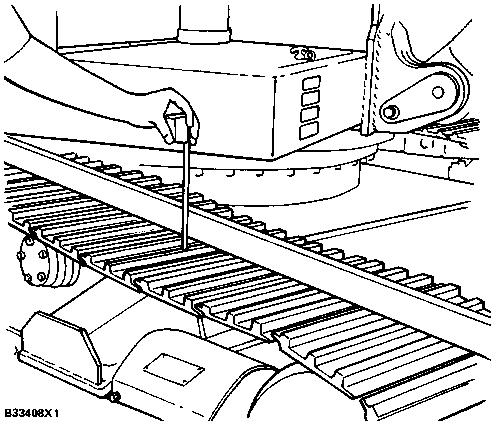
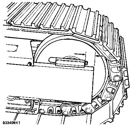
27 Release Of Pressure In The Hydraulic System Release the pressure in the implement hydraulic circuits (boom, stick and bucket) before any hydraulic lines or components are disconnected or removed. Follow this procedure. 1. Fully extend the rod in the stick cylinder. 2. Adjust the position of the bucket so that it will be flat on the ground when the boom is lowered. 3. Lower the boom until the bucket is flat on the ground. 4. Shut off the engine and put the lever for the safety valve in the SAFE position. NOTE: Small valves (bleed valves) have been installed in the boom, stick and bucket circuits. 5. Move the control levers for boom, bucket, stick and swing to all positions. This will relieve any pressure that might be present in the pilot system. 6. Slowly loosen the filler cap on the hydraulic tank and release the pressure. 7. Tighten the filler cap back on the hydraulic tank. 8. Slowly open the bleed valves in the lines to the boom, bucket and stick cylinders. 9. Tighten the bleed valves. 10. The pressure in the system has been released and lines and components can be removed. NOTE: There are no bleed valves in either the swing or track circuits. Normally, any pressure that might be trapped in these lines, will bleed off through the motors. Track Adjustment Procedure. 1. Drive the machine forward in the direction of the idlers. 2. Stop when one track pin is directly over the front carrier roller. 3. The correct adjustment is 25 to 40 mm (1.0 to 1.5 in.) of sag in the track halfway between the front carrier roller and the idler.
28
29 To prevent possible personal injury, never visually inspect the relief valve to see if grease is coming out. Always look at the track to see if it has become loose or tight. Open the relief valve one turn only. NOTICE If the dimension between the end of the track roller frame and the flange on the idler hub (as shown) is less than 16 mm (5/8 in.) do not adjust the track. 4. Remove the plate, covering the fill and relief valves, on the track roller frame. 5. If the track is too loose, add grease in the fill valve until the track sag is correct. 6. If the track is too tight, turn the relief valve counterclockwise one turn and let grease come out until the adjustment is correct. NOTE: It will be necessary to move the machine back and forth to get the pressure equal. 7. Check the adjustment again. 8. If the adjustment is correct, tighten the relief valve and replace the cover plate. Check Of The Adjustment Of Pump Stroking Pressure 1. Disconnect the signal line from the summing valve at the front pump and install a 9S5518 Plug in the end of the line. Leave the port in the pump open. 2. Install a hose, kpa (0-600 psi) gauge and a gate valve, between the outlet side of the filter for the pilot system and the inlet signal port on the pump to be tested.
30 SCHEMATIC DIAGRAM OF TEST ARRANGEMENT 3. Disconnect the pilot line from the stick crossover valve spring (outer) housing and install a plug in the end of the line. Leave the connector on the housing open. 4. Connect a flow meter between the rear pump "TEE TAP" and the return line adapter to tank. 5. Fully open the throttle. Move the stick control to the stick IN position (full open). Turn the load valve on the flow meter in (clockwise) until the pressure gauge reads kpa (2000 psi). 6. Slowly turn the gate valve open (counterclockwise) until pressure on the gauge reads 550 to 830 kpa (80 to 120 psi). Watch the flowmeter closely and write down the signal pressure when the flow through the meter decreases by 4.0 liter/min (1.0 gpm). This is the stroking signal pressure for the front pump. 7. Move the flowmeter connection to the front pump. Move the bucket control valve to the full OPEN position. Turn the load valve on the flowmeter IN (clockwise) until the pressure gauge reads kpa (2000 psi). 8. Do Step 6 again for the rear pump. 9. Check the stroking signal pressures for the two pumps against each other. Each of the signal pressures must be 690 ± 35 kpa (100 ± 5 psi). There must be no more than 25 kpa (4 psi) difference between them. If there is, adjust the shims on the middle spring on the servovalve of the pump that is farther from 690 kpa (100 psi) until it is the same [± 25 kpa (4 psi)] as the other pump. Adjustment And Check Of Swing Relief Valve 1. Carefully open the cap on the filler tube for the hydraulic tank. Let any pressure in the tank out and tighten the cap. 2. Install a 0 to kpa (0 to 6000 psi) pressure gauge in the pressure tap for the rear (swing) pump.

31 NOTE: Remove the plug with care because some oil will come out when it is removed. 3. Install the swing lock pin in the LOCKED position. NOTE: If the pin does not drop into place, start the engine and move the swing control to the right or left until it does. 4. Start the engine. 5. Get the temperature of the oil up to 49 to 65 C (120 to 150 F). 6. Move the swing control lever to the swing RIGHT position. Pressure must read ± 690 kpa (2500 ± 100 psi). 7. Move the swing control lever to the swing LEFT position. Pressure must read ± 690 kpa (2500 ± 100 psi). 8. Add or remove shims as necessary. Add shims to increase the pressure. Remove shims to decrease the pressure. Each 0.18 mm (.007 in.) shim will change the pressure setting 840 kpa (122 psi). Pump Leakage After the pump control tests are complete, it is known that the output of the pump of pilot system oil is correct, the operation of the control valves for pump signal is correct, the relief valve in the pilot system is set correct and operation of the servovalves is correct. If the output of any of the piston pumps is not according to specifications, it is probable that there is too much wear inside the pump. Leakage from the drain openings is an indication of the conditions inside the pump. Disconnect one end of the drain line and let the drain go into a bucket. Measure the amount of leakage per minute. The chart shows permissible leakage rates: Testing Outlet Pressure Of Pilot Oil From The Pilot Valves To The Main Control Valves For Boom, Bucket, Stick And Swing Movement

 pressure gauges in the covers on both ends of the main control valve for stick movement. 3.")
32 Modulation of the pressure for outlet oil from pilot control valves (1) and (4) controls the movement of the stems in the main control valves for boom, bucket, stick and swing. The movement of the stems in the main control valves controls the flow of main system oil to the cylinders or swing motor. Do the steps that follow to test the pressure of the outlet oil from the pilot valves. 1. Install the lock pin to stop swing movement. 2. Install 0 to 4150 kpa (0 to 600 psi) pressure gauges in the covers on both ends of the main control valve for stick movement. 3. With the engine running to keep pilot system pressure at 2300 ± 170 kpa (335 ± 25 psi), check the pressure at the outer end of the stick control valve when spool (3) is moved up: to contact bumper spring... pressure must be 345 ± 105 kpa (50 ± 15 psi) at 6.4 mm (.25 in.)... pressure must be 1135 ± 140 kpa (165 ± 20 psi) PILOT CONTROL VALVE FOR STICK AND SWING CONTROL 1. Pilot control valve for stick and swing movement. 2. Spool for control of swing movement. 3. Spool for control of stick movement. at full travel... pressure must be 2300 ± 170 kpa (335 ± 25 psi) Do Step 3 again with spool (3) moved down. Read the pressure at the inner end of the main control valve. PILOT CONTROL VALVE FOR BOOM AND BUCKET CONTROL 4. Pilot control valve for boom and bucket movement. 5. Spool for control of boom movement. 6. Spool for control of bucket movement. 4. Do Steps 2 and 3 for: Spool (2) and main valve for control of swing movement. Spool (5) and the main valve for control of boom movement.

 5P2390 GAUGE TOOL GROUP 1. Put the pump drive in a position with the engine mounting side down. 2. Install the bearing cage on the center gear.")
33 Spool (6) and the valve for control of bucket movement. There is no adjustment on the pilot valve to change the value of output pressure. If the pressures are not correct from the pilot valve, check to be sure the spools have free movement for full length of travel. Check for restrictions in drilled passages. Adjustment Of Bearings In Pump Drive 5P2390 Gauge Tool Group.8S2328 Dial Test Indicator Group.XT-3 Hose mm (1.5 in.) long 25.4 mm (1.00 in.) inside diameter. (The hose is used on the outer gears only.) 5P2390 GAUGE TOOL GROUP 1. Put the pump drive in a position with the engine mounting side down. 2. Install the bearing cage on the center gear. Use a full shim pack. NOTE: A shim pack has 8 shims 0.15 mm (.006 in.) thick, 1 shim, 0.81 mm (.32 in.) thick and 10 shims 0.05 mm (.002 in.) thick. Total thickness of pack is 2.54 mm (.100 in.) 3. Tighten bolts for bearing cage to 58 ± 7 N m (42 ± 5 lb. ft.). TIGHTENING 5P2390 TOOL GROUP IN GEAR 4. Install the 5P2390 Gauge Tool Group in the bore of the center gear. Upper part of knurled area must be even with upper part of gear spline. NOTE: If tool is installed too far, it will cause errors in the indicator readings.


34 5. Hold the tool in the center of the gear and tighten the nut on the end of the tool until the tool is held tight in the gear. 6. Install the 8S2328 Dial Indicator so the stylus is in position on the end of the center shaft of the 5P2390 Gauge Tool Group. SEATING FRONT GEAR BEARING 7. Hold the tool by the handles. Push down on the tool and turn the gear 90 in each direction six times. This seats the front bearings. 8. Turn the dial indicator to zero (0). NOTE: The indicator stylus must stay on the end of the shaft during the 90 rotations. If it does not, loosen the nut on the tool and be sure it is centered. Set the dial indicator on zero again. 9. Hold the tool by the handle again. Pull up on the handle and turn the gear 90 in each direction six times. This seats the rear bearing. 10. Carefully watch the indicator for the amount of upward travel measured on the dial. This is the total amount of end play with the full shim pack. 11. From this indicator reading, take away 0.20 mm (.008 in.) to find the number of shims to remove from the shim pack to get the correct 0.20 ± 0.05 mm (.008 ±.002 in.) end play adjustment. 12. Remove the tool, bearing cage and shim pack. NOTE: Use a plastic hammer to loosen the center shaft of the tool to prevent damage. SEATING REAR GEAR BEARING 13. Remove the shims that are not needed.
Implement and Steering/Hydraulic System Testing and Adjusting
 Page 1 of 64 Testing And Adjusting Introduction Reference: This supplement contains the Specifications, Systems Operation, and Testing And Adjusting for the components and systems that are different than
Troubleshooting The Transmission Hydraulic System
 416B, 426B, 428B, 436B, & 438B BACKHOE LOADERS TRANSMISSION Testing And Adjusting Troubleshooting The Transmission Hydraulic System Make reference to the following warning and pressure tap locations for
Troubleshooting the Transmission Hydraulic System
 Testing and Adjusting IT28F INTEGRATED TOOLCARRIER POWER TRAIN Testing And Adjusting Introduction Reference: For Specifications with illustrations, refer to SENR5974, IT28F Integrated Toolcarrier Power
Troubleshooting, Service Tips, And Major Improvements For Hydrostatic Transmissions (Special Edition){3200}
{3200}") Page 1 of 75 Troubleshooting, Service Tips, And Major Improvements For Hydrostatic Transmissions (Special Edition){3200} 943, 953, 963, 973 Loaders Introduction The hydrostatic transmissions used in 943,
Page 1 of 75 Troubleshooting, Service Tips, And Major Improvements For Hydrostatic Transmissions (Special Edition){3200} 943, 953, 963, 973 Loaders Introduction The hydrostatic transmissions used in 943,
Pilot Oil Supply Circuit
 Pilot Oil Supply Circuit Introduction Pilot system oil output from pilot pump (42) has the following three main functions: 1. To control main pump output. 2. To provide easier operation of control levers.
Media Number -SENR Publication Date -01/07/1992 Date Updated -11/10/2001
 518 GRAPPLE SKIDDER--SERIES II 95U03200-UP (MACHINE) POWERED BY 330 Page 1 of 16 Model: 518 WHEEL SKIDDER 95U Configuration: 518 GRAPPLE SKIDDER--SERIES II 95U03200-UP (MACHINE) POWERED BY 3304 ENGINE
Introduction. General Information. Systems Operation
 Systems Operation Introduction Reference: For illustrated Specifications, refer to the Specifications For 416, 426, 428, 436, 438, & Series II Backhoe Loaders Transmission, Form No. SENR3131. If the specifications
Media Number -SENR Publication Date -01/10/1977 Date Updated -12/10/2001
 - - 55, 56, 57, 58 & 59 TOWING WINCHES Page 1 of 21 Testing and Adjusting 55, 56, 57, 58 & 59 TOWING WINCHES Media Number -SENR7217-01 Publication Date -01/10/1977 Date Updated -12/10/2001 Testing And
Hydrostatic System - Test and Adjust
 Testing and Adjusting 236B, 246B, 252B and 262B Skid Steer Loaders Hydraulic System Media Number -RENR4867-03 Publication Date -01/11/2009 Date Updated -24/11/2009 Hydrostatic System - Test and Adjust
Section 35 Chapter 2 HYDRAULIC SYSTEM HOW IT WORKS AND TROUBLESHOOTING NH
 Section 35 Chapter HYDRAULIC SYSTEM HOW IT WORKS AND TROUBLESHOOTING 6-80NH TABLE OF CONTENTS GENERAL INTRODUCTION... 35-3 Hydraulic Pumps... 35-3 Standard Flow PFC Pump Layout... 35-5 MegaFlow PFC Pump
Torque Converter, Transmission Pump, Screen And Filter
 Page 13 of 27 Transmission Hydraulic System In Forward (Engine Running - Type 2 & 3 Control Valve Shown) (4) Transmission control valve. (5) Neutralizer valve. (6) Neutralizer solenoid. (7) Flow control
STEERING HYDRAULICS The steering system is a flow amplified, load sensing, hydraulics arrangement.
 STEERING HYDRAULICS 116821 The steering system is a flow amplified, load sensing, hydraulics arrangement. When the steering wheel is turned, the Steering Metering Pump meters an oil volume proportional
k. Components not properly adjusted. Refer to machine technical manual for proper adjustment of components.
 General Troubleshooting Charts General Troubleshooting Charts Use the charts on the following pages to help in listing all the possible causes of trouble when you begin diagnosing and testing of a machine.
Track Drive Circuit - General System. Simplified Travel Circuit Diagrams: Neutral Controls Forward Travel Reverse Travel
 Section 7.1 Track Drive Circuit - General System Simplified Travel Circuit Diagrams: Neutral Controls... 7.1.2 Forward Travel... 7.1.4 Reverse Travel... 7.1.5 General... 7.1.3 Track Drive Circuit: General...
Section 7.1. Wheel Drive Circuit - General System
 Section 7.1 Wheel Drive Circuit - General System Simplified Travel Circuit Diagrams: Neutral Controls... 7.1.2 Forward Travel... 7.1.4 Reverse Travel... 7.1.5 General... 7.1.3 Wheel Drive Circuit: General...
BOLT-ON AND WELD-ON FLUSH FLOOR SLIDEOUT SYSTEMS OPERATION AND SERVICE MANUAL
 BOLT-ON AND WELD-ON FLUSH FLOOR SLIDEOUT SYSTEMS OPERATION AND SERVICE MANUAL TABLE OF CONTENTS SYSTEM...... Warning........ Description...... Prior to Operation OPERATION... Main Components... Mechanical...
Section 6.1. Implement Circuit - General System. General: TF Configuration TB Configurations Implement Control Valve:
 Section 6.1 Implement Circuit - General System General: TF Configuration... 6.1.3 TB Configurations... 6.1.5 Implement Pump Breakdown... 6.1.6 Operational Description: General... 6.1.7 Compensator Control...
Section 6.1. Implement Circuit - General System. General: Implement Control Valve:
 Section 6.1 Implement Circuit - General System General: Implement Circuit... 6.1.3 Implement Pump Breakdown... 6.1.4 Operational Description: General... 6.1.5 Compensator Control... 6.1.6 Standby Condition...
955L Traxcavator S/n 64J, 71J & 85J Volume 1 of 2
 Caterpillar Service Manual 955L Traxcavator S/n 64J, 71J & 85J Volume 1 of 2 Service Manual THIS IS A MANUAL PRODUCED BY JENSALES INC. WITHOUT THE AUTHORIZATION OF CATERPILLAR OR IT S SUCCESSORS. CATERPILLAR
Section 6.1. Implement Circuit - General System. General: Implement Control Valve: Implement Circuit
 Section 6.1 Implement Circuit - General System General: Implement Circuit... 6.1.3 Implement Pump Breakdown... 6.1.4 Operational Description: General... 6.1.5 Compensator Control... 6.1.6 Standby Condition...
MCV106A. Hydraulic Displacment Control-PV DESCRIPTION FEATURES ORDERING INFORMATION. BLN Issued: March 1991
 DESCRIPTION MCV106A Hydraulic Displacment Control-PV Issued: March 1991 The MCV106A Hydraulic Displacement Control (HDC) is a costeffective hydraulic pump stroke control which uses mechanical feedback
WEBER CARBURETOR TROUBLESHOOTING GUIDE
 This guide is to help pinpoint problems by diagnosing engine symptoms associated with specific vehicle operating conditions. The chart will guide you step by step to help correct these problems. For successful
Section 6.1. Implement Circuit - General System. General: TF Configuration TB Configurations Implement Control Valve:
 Section 6.1 Implement Circuit - General System General: TF Configuration... 6.1.3 TB Configurations... 6.1.5 Implement Pump Breakdown... 6.1.6 Operational Description: General... 6.1.7 Compensator Control...
LC I LIPPERT COMPONENTS HYDRAULIC FULL WALL SLIDEOUT SYSTEM OPERATION AND SERVICE MANUAL
 LC I LIPPERT COMPONENTS HYDRAULIC FULL WALL SLIDEOUT SYSTEM OPERATION AND SERVICE MANUAL TABLE OF CONTENTS SYSTEM...... 3 Warning...... 3 Description..... 3 Prior to Operation... 4 4 OPERATION... Main
Open Center Compact Valve Custom Installation Guide Rev A
 200-0762-01 Open Center Compact Valve Custom Installation Guide 602-0575-01 Rev A 2014-12 Overview This guide provides information for completing a custom AutoSteer valve installation on wheeled farm vehicles
Hydrostatic Drive. 1. Main Pump. Hydrostatic Drive
 Hydrostatic Drive The Hydrostatic drive is used to drive a hydraulic motor at variable speed. A bi-directional, variable displacement pump controls the direction and speed of the hydraulic motor. This
BRAKE SYSTEM, HYDRAULICALLY ACTUATED - 631G TRACTOR Cat Tractors with standard shoe/drum brakes
 BRAKE SYSTEM, HYDRAULICALLY ACTUATED - 631G TRACTOR 194139 631 Cat Tractors with standard shoe/drum brakes Kress Corporation modifies the Caterpillar tractor air actuated shoe brake system to a hydraulically
TC Series Cooling Systems
 TC Series Cooling Systems Table of Contents Table of Contents...1 List of Figures...1 Safety...2 Introduction...2 General Specifications...2 Types of Coolant...2 Routine Maintenance...2 Surge Tank Coolant
OPERATOR S MANUAL Model 60010
 OPERATOR S MANUAL Model 60010 10- TON SNAP LOCK PORTA POWER SET W/ WHEELED CASE PROFESSIONAL HYDRAULIC JACKS 1531 W. Mohawk Drive Phone 715-453-9602 Customer Service 800-995-2250 Tomahawk, WI 54487 Fax
Hydro-Sync Slide-Out System
 Hydro-Sync Slide-Out System SERVICE MANUAL Rev: 08.14.2018 Hydro-Sync Slide-out System Service Manual TABLE OF CONTENTS Safety Information 3 Product Information 3 Operation 4 Extending Slide-Out Room 4
TWO-STAGE HYDRAULIC PUMP. RWP55-IBT-Air
 ORIGINAL INSTRUCTIONS Form No.1000458 5 SPX Corporation 5885 11th Street Rockford, IL 61109-3699 USA Tech. Services: (800) 477-8326 Fax: (800) 765-8326 Order Entry: (800) 541-1418 Fax: (800) 288-7031 Internet
HexPro Series Low Profile Wrenches
 HexPro Series Low Profile Wrenches Operation and Maintenance Manual Model 2HP 4HP 8HP 14HP 30HP www.torquetoolsinc.com Use the HEXPRO Series Low Profile Wrenches Model 2HP 4HP 8HP 14HP 30HP to install
Injector. General Information CAUTION. Use only the specified injector for the engine.
 Page 1 of 32 006-026 Injector General Information CAUTION Use only the specified injector for the engine. All engines use closed nozzle, hole-type injectors. However, the injectors can have different part
Ideal Installation. I & M Mark 67 (1/2 6 ) Control Line. Installation & Maintenance Instructions for Mark 67 Pressure Regulators
 Control Line. Installation & Maintenance Instructions for Mark 67 Pressure Regulators") I & M Mark (/ ) 0 Wasson Road Cincinnati, OH 0 USA Phone --00 Fax -8-00 info@richardsind.com www.jordanvalve.com Installation & Maintenance Instructions for Mark Pressure Regulators Warning: Jordan Valve
I & M Mark (/ ) 0 Wasson Road Cincinnati, OH 0 USA Phone --00 Fax -8-00 info@richardsind.com www.jordanvalve.com Installation & Maintenance Instructions for Mark Pressure Regulators Warning: Jordan Valve
Troubleshooting of the LubeTech Grease System
 Troubleshooting of the LubeTech Grease System February 2009 The LubeTech grease system is designed to be a preventative maintenance system that will extend the life of your bearings that are connected
STEERING 19-1 STEERING CONTENTS
 PL STEERING 19-1 STEERING CONTENTS page GENERAL INFORMATION... 1 POWER STEERING PUMP... 9 page STEERING COLUMN... 35 STEERING GEAR... 26 GENERAL INFORMATION INDEX page GENERAL INFORMATION STEERING SYSTEM
Oregon Fuel Injection
 Cummins PT Fuel Pump Diagnostic No Start, with no smoke 1. This could be caused by the fuel pump not turning or a seized gear pump. Remove the fuel supply hose and the fuel inlet fitting from the gear
SECTION 4 - FUEL/LUBRICATION/COOLING
 For Arctic Cat Discount Parts Call 606-678-9623 or 606-561-4983 SECTION 4 - FUEL/LUBRICATION/COOLING 4 TABLE OF CONTENTS Carburetor Specifications... 4-2 Carburetor Schematic... 4-2 Carburetor... 4-3 Cleaning
Filling and Flushing the Hydraulic System - Test
 Filling and Flushing the Hydraulic System - Test Personal injury or death can result from improperly checking for a leak. Always use a board or cardboard when checking for a leak. Escaping air or fluid
Low Profile Wrenches Operation and Maintenance Manual
 Low Profile Wrenches Operation and Maintenance Manual http://www.torquetoolsinc.com Use the HEXPRO Series Low Profile Wrenches Model 2HP 4HP 8HP 14HP 30HP to install and remove large bolts that have minimal
Maintenance Information
 51984144 Edition 6 May 2014 Air Paving Breaker MX60 & MX90 Maintenance Information Save These Instructions Product Safety Information WARNING Failure to observe the following warnings, and to avoid these
Woodward PSG Governor
 Woodward PSG Governor Linkage Adjustment PSG GOVERNOR CONTROL LINKAGE 1. Rod assembly. 2. Lever. 3. Lever. 1. Make sure levers (2 and 3) are at the SHUTOFF position (fully counterclockwise). 2. With both
Power Train. Chapter 5
 Chapter Power Train Spefications................................................................. -3 Test Spefications........................................................ -3 Repair Spefications.......................................................
SERVICE MANUAL Gearbox - Allison AT545 - Gearbox Installation
 Gearbox - Allison AT545 - Gearbox Installation Oil level dipstick Gearbox oil cooler Auxiliary oil filter Modulator Page 3.4 Gearbox - Allison AT545 Checking Oil Level The dipstick and filler are situated
Hydraulic Maintenance & Troubleshooting. Content - Norman Kronowitz Presenter Jim Trinkle
 Hydraulic Maintenance & Troubleshooting Content - Norman Kronowitz Presenter Jim Trinkle Introduction Welcome to the CMA/Flodyne/Hydradyne s Hydraulic Troubleshooting presentation. We will introduce many
951B Traxcavator S/n 79H, 32F, 69H & 86J Volume 1 of 2
 Caterpillar Service Manual 91B Traxcavator S/n 79H, 2F, 9H & 8J Volume 1 of 2 Service Manual THIS IS A MANUAL PRODUCED BY JENSALES INC. WITHOUT THE AUTHORIZATION OF CATERPILLAR OR IT S SUCCESSORS. CATERPILLAR
DIAGNOSIS AND TESTING
 211-00-1 Steering System General Information 211-00-1 DIAGNOSIS AND TESTING Steering System Special Tool(s) Dial Thermometer 0-220 F 023-R0007 or equivalent Material Item MERCON Multi-Purpose (ATF) Transmission
RUFNEX Series Low Profile Wrenches Operation and Maintenance Manual
 RUFNEX Series Low Profile Wrenches Operation and Maintenance Manual http://www.torsionx.com Use the RUFNEX Series Ultra-Low Profile Wrenches to install and remove large bolts that have minimal wrench clearance.
Twin Power. Manual. Pneumatic Multiturn actuator in Standard and ATEX design WARNING! WARNING! Mounting. Assembly example
 Top Quality Valve Actuators Made in Sweden Twin Power Manual Pneumatic Multiturn actuator in Standard and ATEX design Mounting The Twin Power actuator works beyond reproach in all positions. Valves with
Purging Air From Divider Block Lubrication Systems
 FROST ENGINEERING SERVICE Purging Air From Lubrication Systems A D I V I S I O N O F G E C S E Y S A L E S & S E R V I C E DESCRIPTION Divider block lubrication systems operate correctly only when all
1991 TRANSMISSION SERVICING Automatic Transmission. Mitsubishi: Eclipse, Galant, Mirage, Montero, Pickup, Precis, 3000GT
 Article Text ARTICLE BEGINNING 1991 TRANSMISSION SERVICING Automatic Transmission Mitsubishi: Eclipse, Galant, Mirage, Montero, Pickup, Precis, 3000GT IDENTIFICATION MITSUBISHI AUTOMATIC TRANSMISSION APPLICATIONS
Tool And Material Checklist
 HOW - TO FUEL PUMPS Tool And Material Checklist Quart Container Service Manual Flare Nut Wrenches Open-end Wrenches Hand Air Pump Fuel Pressure Gauge Socket Wrenches Scraper Gasket Sealer Gasket Voltmeter
Table 6-1. Problems and solutions with pump operations. No Fluid Delivery
 Table 6-1. and solutions with pump operations No Fluid Delivery Fluid level in the reservoir is low. Oil intake pipe or inlet filter is plugged. Air leak in the inlet line prevents priming or causes noise
Sofa Slideout Assembly OWNER'S MANUAL. Rev: Page 1 Sofa Slideout Owners Manual
 Sofa Slideout Assembly OWNER'S MANUAL Rev: 06.14.2016 Page 1 Sofa Slideout Owners Manual TABLE OF CONTENTS Warning, Safety, and System Requirement Information 3 Product Information 3 Prior to Operation
Embedded Rack Slide-out System
 Embedded Rack Slide-out System SERVICE MANUAL Rev: 02.16.2017 Page 1 Electric Embedded Rack Slide-out System TABLE OF CONTENTS Safety Information 3 Product Information 3 Operation 4 Extending Slide-Out
CAUTION. Start & Stop Procedures. Section 4-2. Engine Oil Level
 Section 4-2 Start & Stop Procedures Before operating this machine, the operator must have: received operator training, a familiarity with this manual, and a complete understanding of all the procedures
Air Assist Bottle Jack Max. Capacity: 12 Tons (4313C) & 20 Tons (4321C) Operating Range: psi
 & 20 Tons (4321C) Operating Range: psi") Form No. 545742 Parts List and Operating Instructions for: 4313C 4321C Air Assist Bottle Jack Max. Capacity: 12 Tons (4313C) & 20 Tons (4321C) Operating Range: 40 150 psi 45 44 43 42 41 40 39 22 1 37 28
Form No. 545742 Parts List and Operating Instructions for: 4313C 4321C Air Assist Bottle Jack Max. Capacity: 12 Tons (4313C) & 20 Tons (4321C) Operating Range: 40 150 psi 45 44 43 42 41 40 39 22 1 37 28
AUTOMATIC CLUTCH Models
 AUTOMATIC CLUTCH 1940 Models Source of this material is from 1940 Series, Issue 4, January 1940 Hudson Service Magazine AUTOMATIC CLUTCH 1940 MODELS The automatic clutch installation and adjustment procedure
CAUTION. Start & Stop Procedures. Section 1-2. Engine Oil Level
 Section 1-2 Start & Stop Procedures Before operating this machine, the operator must have: received operator training, a familiarity with this manual, and a complete understanding of all the procedures
OPERATING INSTRUCTIONS & SERVICE MANUAL BLUE MAX II HYDROSTATIC TEST PUMP
 PAGE 1 OF 10 OPERATING INSTRUCTIONS & SERVICE MANUAL BLUE MAX II HYDROSTATIC TEST PUMP EFFICIENT, EASY OPERATION Air operated pump Wide range of pressures and volumes Easy to operate controls Output pressure
Lesson 5: Directional Control Valves
 : Directional Control Valves Basic Hydraulic Systems Hydraulic Fluids Hydraulic Tank Hydraulic Pumps and Motors Pressure Control Valves Directional Control Valves Flow Control Valves Cylinders : Directional
ELECTRIC BEDROOM SLIDEOUT SYSTEM OPERATION AND SERVICE MANUAL
 ELECTRIC BEDROOM SLIDEOUT SYSTEM OPERATION AND SERVICE MANUAL TABLE OF CONTENTS SYSTEM...... Warning...... Description..... Prior to Operation... System Maintenance..... OPERATION... Warning... Extending
CAB TILT HYDRAULIC SYSTEM
 OPERATION, MAINTENANCE and SERVICE INSTRUCTIONS CAB TILT HYDRAULIC SYSTEM WITH POWER-PACKER PUMP, CYLINDERS and LATCHES A division of Actuant Corporation 1-800-745-4142 1 www.powerpackerus.com Notice The
Collision Repair Set. Form No No. 1517A 4-Ton Set. No. 1519A 10-Ton Set. Parts List & Operating Instructions for: 1519A. Part No. Item No.
 SPX Corporation 655 Eisenhower Drive Owatonna, MN 55060-0995 USA Phone: (507) 455-7000 Tech. Serv.: (800) 533-6127 Fax: (800) 955-8329 Order Entry: (800) 533-6127 Fax: (800) 283-8665 International Sales:
ANDERSON GREENWOOD SERIES 500 PILOT OPERATED SAFETY RELIEF VALVES INSTALLATION AND MAINTENANCE INSTRUCTIONS
 Before installation these instructions must be fully read and understood TABLE OF CONTENTS 1. General valve description and start-up... 1 2. Main valve maintenance... 1 3. Pilot maintenance... 5 4. Pilot
980 B Wheel Loader S/n 89P1 & Up Volume 1 of 2
 Caterpillar Service Manual 980 B Wheel Loader S/n 89P1 & Up Volume 1 of 2 Service Manual THIS IS A MANUAL PRODUCED BY JENSALES INC. WITHOUT THE AUTHORIZATION OF CATERPILLAR OR IT S SUCCESSORS. CATERPILLAR
PNEUMATICS CONTENTS HST-TAMPER
 CONTENTS Tamper Pneumatic Component Locations...2 Manually Releasing Air Brakes... 3 Releasing Air Pressure... 4 Removing Water from Air Tanks... 4 Adjusting Air Compressor Governor... 4 Check/Replace
AIR BRAKES THIS SECTION IS FOR DRIVERS WHO DRIVE VEHICLES WITH AIR BRAKES
 Section 5 AIR BRAKES THIS SECTION IS FOR DRIVERS WHO DRIVE VEHICLES WITH AIR BRAKES AIR BRAKES/Section 5 SECTION 5: AIR BRAKES THIS SECTION COVERS Air Brake System Parts Dual Air Brake Systems Inspecting
TIME LAG TEST Check the automatic transmission (each clutch, brake and gear) for wear.
 for wear.") AT2 TROUBLESHOOTING 1. GENERAL INFORMATION (a) Troubles occurring with the automatic transmission can be caused by either the engine, electrical control or the transmission itself. These 3 areas should
AT2 TROUBLESHOOTING 1. GENERAL INFORMATION (a) Troubles occurring with the automatic transmission can be caused by either the engine, electrical control or the transmission itself. These 3 areas should
Fig Variable Speed Valve Parts
 5 DISASSEMBLY OF VARIABLE SPEED CONTROL VALVE (Seal Replacement with Control Valve in the Bobcat). Remove seat and seat plate (Fig. ).. Remove variable speed control lever linkage rod. 3. Remove temperature
Fisher 1061 Pneumatic Piston Rotary Actuator with Style H & J Mounting Adaptations
 Instruction Manual 1061 H & J Actuator Fisher 1061 Pneumatic Piston Rotary Actuator with Style H & J Mounting Adaptations Contents Introduction... 1 Scope of Manual... 1 Description... 2 Specifications...
Maintenance Information
 16573347 Edition 2 February 2014 Air Grinder Series 88H Maintenance Information Save These Instructions Product Safety Information WARNING Failure to observe the following warnings, and to avoid these
Service Bulletin Trucks Date Number Page
 Mack Trucks, Inc. Allentown, PA USA (Also applies to Mack Trucks Australia, Operation and Adjustment Only, CXX, CLX, CMH, CMM and CSM Models) (Supersedes SB313005 dated 03/24/08) Service Bulletin Trucks
High Lift Transmission Jack
 655 Eisenhower Drive Owatonna, MN 55060-0995 USA Phone: (507) 455-7000 Tech. Serv.: (800) 533-6127 Fax: (800) 955-8329 Order Entry: (800) 533-6127 Fax: (800) 283-8665 International Sales: (507) 455-7223
ENGINE TUNE-UP INSPECTION OF ENGINE COOLANT INSPECTION OF ENGINE OIL INSPECTION OF BATTERY. INSPECTION OF AIR FILTER (Paper Filter Type)
") ENGINE MECHANICAL - Engine Tune-Up EM-17 ENGINE TUNE-UP INSPECTION OF ENGINE COOLANT (See steps 1 and 2 on page CO-4) INSPECTION OF ENGINE OIL (See steps 1 and 2 on page LU-5) INSPECTION OF BATTERY (See
ENGINE MECHANICAL - Engine Tune-Up EM-17 ENGINE TUNE-UP INSPECTION OF ENGINE COOLANT (See steps 1 and 2 on page CO-4) INSPECTION OF ENGINE OIL (See steps 1 and 2 on page LU-5) INSPECTION OF BATTERY (See
CHEETAH E-SHIFT Pro Series Valve Body (Positively Not For Street Use) Fits Torqueflite 727 & (Non Lock-Up)
 Fits Torqueflite 727 & (Non Lock-Up)") 1535 Owens Road, Jacksonville, FL 32218 - (904)741-4850 - FAX (904)741-4853 www.turboaction.com CHEETAH E-SHIFT Pro Series Valve Body (Positively Not For Street Use) Fits Torqueflite 727 & 904 1966-90
1535 Owens Road, Jacksonville, FL 32218 - (904)741-4850 - FAX (904)741-4853 www.turboaction.com CHEETAH E-SHIFT Pro Series Valve Body (Positively Not For Street Use) Fits Torqueflite 727 & 904 1966-90
John Deere. MODEL: 8430 & 8630 Volume 1 of 2 JD-S-TM1143
 John Deere MODEL: 8430 & 8630 Volume 1 of 2 THIS IS A MANUAL PRODUCED BY JENSALES INC. WITHOUT THE AUTHORIZATION OF JOHN DEERE OR IT'S SUCCESSORS. JOHN DEERE AND IT'S SUCCESSORS ARE NOT RESPONSIBLE FOR
INSTALLATION/OPERATING INSTRUCTIONS TEMPERING VALVE HOT C GASKET STANDARD PIPE TAP MIXED HOT COLD HOT INLET INLET 3/4" 1" 1 1/4" 3/4" 1 1/4"
 INSTALLATION/OPERATING INSTRUCTIONS NIPPLE A MIXED OUTLET INSERT "O" RING MIXER VALVE BODY COLD OUTLET B SPRING COLD INLET C O L D FAIRFIELD, N.J. R H O T INLET GUIDE PISTON C GASKET BONNET ADJUSTING SCREW
Operating instructions Form no safety definitions
 Operating instructions Form no. 1000437 safety definitions safety symbols are used to identify any action or lack of action that can cause personal injury. Your reading and understanding of these safety
1 Green Pressure Regulator Spring Automatic transmissions operate at temperatures between 150ºF and
 Installation Instructions for 603107 Valve Body Kit C-4 1970 & Later Tools Required Speed Handle or Ratchet 3/8 Drive 1/2 Socket 3/8 Drive 7/16 Socket 3/8 Drive 5/16 Socket 3/8 Drive Small Screwdriver
SERVICE INSTRUCTIONS D TON
 1120 SOUTH CRYSTAL AVE * BENTON HARBOR MI PH: 269-925-7777 FAX: 269-925-6656 SERVICE INSTRUCTIONS D-51223 4 TON TO ASSEMBLE: 1. Check the handle set screw for tightness. CUSTOMER PRE-USE INSTRUCTIONS THE
Section 10 Chapter 17
 Section 10 Chapter 17 24 Valve, 8.3 Liter Engine Air Intake System Note: All coding used in the 8.3 Liter and 9 Liter engine manuals are Cummins engine codes. These engine codes have no meaning to New
Installation Manual. Model T675A Engine Brakes. For Mack 6 Cylinder, 2 valve Head ENDT-673, 675, 676 & E6 Series Engines.
 Engine Brakes Installation Manual Model T675A Engine Brakes For Mack 6 Cylinder, 2 valve Head ENDT-673, 675, 676 & E6 Series Engines TecBrake P.O. Box 27822 Houston, Texas 77227 INSTALLATION MANUAL TECBRAKE
Servo and Proportional Valves
 Servo and Proportional Valves Servo and proportional valves are used to precisely control the position or speed of an actuator. The valves are different internally but perform the same function. A servo
INSTRUCTION MANUAL IM-422 For HTC/COUPLING ASSEMBLY HC-8088
 No Revision 2/22/18 INSTRUCTION MANUAL IM-422 HTC/COUPLING ASSEMBLY The Riverhawk Company reserves the right to make changes updating this document without dissemination or notice. The latest revision
4 - Way Control 4 - Way Control 4 - Way Control with lock
 INSTALLATION / OPERATION / MAINTENANCE 1. DESCRIPTION MODEL 0-02 (Full Internal Port) Powertrol Valve This manual contains information for installation, operation and maintenance of the Cla-Val Co. 0-02
Service Jack. Form No Parts List & Operating Instructions 1510B. Max. Capacity: 5 and 10 Tons. 1 of 3. Sheet No. Issue Date: Rev.
 SPX Corporation 655 Eisenhower Drive Owatonna, MN 55060-0995 USA Phone: (507) 455-7000 Tech. Serv.: (800) 533-6127 Fax: (800) 955-8329 Order Entry: (800) 533-6127 Fax: (800) 283-8665 International Sales:
CH.4 Basic Components of Hydraulic and Pneumatic System/16 M HAP/17522/AE5G
 Content : 4.1 Hydraulic and Pneumatic actuators. 10 Marks Hydraulic Actuators - Hydraulic cylinders (single, double acting and telescopic) construction and working, Hydraulic motors (gear and piston type)
Performer Series Carburetor Rebuild Kit Catalog #1477 Models
 Please read these instructions carefully before attempting to rebuild your carburetor. Make sure to refer to your carburetor Owner s Manual for further information if need be. If you have any questions
CIRRUS AIRPLANE MAINTENANCE MANUAL
 1. GENERAL This chapter contains information on the storage, distribution, and indicating components of the fuel system. The engine is supplied with fuel drawn out of the left or right integral fuel tank
Check Valves Check Valves are the simplest form of directional control valves, but they can also be used as pressure controls.
 Check Valves Check Valves are the simplest form of directional control valves, but they can also be used as pressure controls. Standard Check Valve The standard check valve permits free flow in one direction
Sachs 48mm Closed Cartridge fork Service Manual
 Sachs 48mm Closed Cartridge fork Service Manual 1 Fork seal driver 2 Special soft jaws 3 Fork cap wrench 4 Rebound rod holding tool 5 Compression assembly holding tool 6 Retaining clip tool Special Tools
Under Axle Jack Max. Capacity: 25 Tons
 SPX Corporation 655 Eisenhower Drive Owatonna, MN 55060-0995 USA Phone: (507) 455-7000 Tech. Serv.: (800) 533-6127 Fax: (800) 955-8329 Order Entry: (800) 533-6127 Fax: (800) 283-8665 International Sales:
Standard Valves Series Globe Valves Series Angle Valves Series Way-Valves
 Installation, Operation, Maintenance Instructions Standard Valves Series 035 000 Globe Valves Series 031 000 Angle Valves Series 033 000 3-Way-Valves 1 GENERAL INFORMATION These instructions are designed
OWNER S MANUAL. Model: UTL-60-12V ( ) (60 Gallon Lawn & Garden Utility Sprayer w/5-nozzle Boom)
 (60 Gallon Lawn & Garden Utility Sprayer w/5-nozzle Boom)") OWNER S MANUAL Model: UTL-60-12V (5301347) (60 Gallon Lawn & Garden Utility Sprayer w/5-nozzle Boom) Technical Specifications 60 Gal. Corrosion-Resistant Polyethylene Tank Deluxe Pistol-Grip Handgun w/25
OWNER S MANUAL Model: UTL-60-12V (5301347) (60 Gallon Lawn & Garden Utility Sprayer w/5-nozzle Boom) Technical Specifications 60 Gal. Corrosion-Resistant Polyethylene Tank Deluxe Pistol-Grip Handgun w/25
Air Assist Bottle Jack Max. Capacity: 12 Tons (4313C) & 20 Tons (4321C) Operating Range: psi
 & 20 Tons (4321C) Operating Range: psi") R SPX Division 655 Eisenhower Drive Owatonna MN 55060 Phone: (507) 455-7000 Tech. Serv.: (800) 533-6127 Fax: (800) 955-8329 Order Entry: (800) 533-6127 Fax: (800) 283-8665 International Sales: (507) 455-7223
R SPX Division 655 Eisenhower Drive Owatonna MN 55060 Phone: (507) 455-7000 Tech. Serv.: (800) 533-6127 Fax: (800) 955-8329 Order Entry: (800) 533-6127 Fax: (800) 283-8665 International Sales: (507) 455-7223
Tests & Adjustments - General Machine. General Safety Hydraulic Tank Turbo Boost Regulator
 Section 8.1 Tests & Adjustments - General Machine General Safety......................................... 8.1.2 Hydraulic Tank Turbo Boost Regulator........................ 8.1.2 Hydraulic Tank Safety
FOX Racing Shox Bypass Technical Manual.
 FOX Racing Shox Bypass Technical Manual. The following technical manual will be using a 2.5 dia. shock with three tubes for descriptions and illustrations. Your shock may differ in the number of tubes,
Troubleshooting Guide
 Troubleshooting Guide diesel - gasoline - LPG P/N 0172021 June 1999 P.O. Box 1160 St. Joseph, MO 64502-1160 1-800-255-0317 Fax: 816-360-9379 www.snorkelusa.com GENERAL INFORMATION This manual contains
 Operation and Maintenance Manual http://www.torsionx.eu Use the MaxDrv Series Square Drive Torque Wrench Model.75, 1, 3, 5, 8, 10, 20, 25, 35, 50 to install and remove threaded fasteners requiring precise