Operating & Maintenance Manual For Steam Conditioning Valve
|
|
|
- Barry King
- 5 years ago
- Views:
Transcription

1 For Steam Conditioning Valve 1
2 Table of Contents 1.0 Introduction Product description Safety Instruction Installation and Commissioning Valve Disassembly Maintenance Valve Reassembly Nozzle Maintenance Replacement Parts 9 Table. 1 Stud Torque 10 Table. 2 Trouble Diagnosis 11 Figure 1 Removing the Nozzle Holder 9 Figure 2 Steam Conditioning Valve Description 12 2

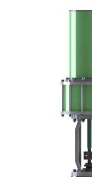
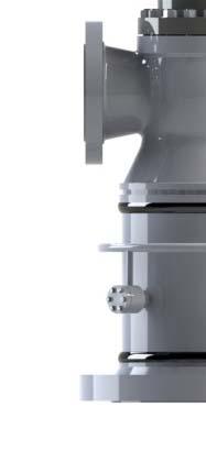
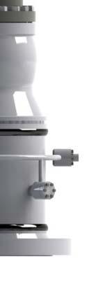
3 1.0 Introduction General This instruction manual included installation, operation and maintenance information for Steam Conditioning Valves. Please refer to separate manuals for instructions covering controllers and positioners. This operating manual covers the areas of installation, commissioning, maintenance, storage, packaging and transport. Personnel qualification Transport, installation, commissioning, maintenance or repair must only be performed by trained or instructed personnel. Safety Information Danger, Warning, Caution symbols, where necessary, to alert you to safety related or other important information. In order to ensure successful and safe operation of our valves the entire operation manual must have been read through and understood prior to installation and commissioning, 2.0 Product description Description This Steam Conditioning Valves are custom designed to fit customer's difficult applications. Specially the valves are designed for horizontal application in steam pipe line. Inner parts of valve are linked with each other not to damaged a cage, a plug, a seat ring when pull those back from the body for maintenance. Balance cage control trim is used with the steam flowing down through the characterized ports in the cage. The pressure drop occurs at the flow area of the cage's port with the port's contour characterizing flow as linear or equal percent. Valves are equipped standard with spring diaphragm pneumatic actuators, either reverse acting or direct acting type. Both actuator types are available in a range of sizes and with a selection of springs to suit the operating conditions. Valve identification A nameplate is fixed to the side of actuator yoke. The nameplate lists the serial number, model number as well as other information such as size, rating, materials, Cv, stroke.,etc. 3
4 When ordering replacement of parts, please refer to the serial and model numbers on the nameplate. 3.0 Safety Instruction Product safety The valves comply with the state of the art and the recognized rules of technical safety, but dangers can still arise. Operate the valves only in perfect condition taking into account the entire operating manual.! Warning: Use of material-incompatible media, exceeding the limit values of medium pressure and temperature and mechanical additional loads such as caused by connected pipelines can result in failure of the valve materail and bursting of the valve. Product specific dangers 1. Use of a medium unsuitable for the valve The valve materials are compatible only with steam. Please contact the manufacturer when used for media requiring or excluding certain media.! Danger! When using unintended media, the materials included in the valve may be attacked or could even be combusted explosively with fatal consequences. For the reason, only use media for which the valve has been approved. 2. Exceeding the permissible pressure with risk of bursting A cause for such exceeding could be for instance so-called closing hammer or cavitation. Closing hammer are pressure peaks, which occur when a pipe is closed by means of a valve.! Warning: Maximum allowable pressures for the valve body and actuator and the maximum allowable pressure at the maximum temperature for the valve are shown on the nameplate mounted on the actuator. 3. Leakage of dangerous substances Dangerous substances can leak for instance from relief bores or when disassembling the valve.! Warning: Collect and dispose of dangerous media (for instance leakages from relief bores or traces of medium remaining during the disassembly of the valve) so that persons and the environment are not endangered. Observer the legal regulations. 4
5 Emergency information In the event of fires, use only such extinguishing agents as are suitable for the extinguishing of corresponding electrical systems. Ensure that the extinguishing agent does not result in a dangerous reaction together with possibly leaking medium. 4.0 Installation and commissioning! Danger Before disassembly, all pressures in this device must be relieved. Failure to relieve pressures may result in personal injury or device damage. Before installing the valve, inspect it for any shipment damage and for any foreign material that may have collected during crating and shipment. Remove flange protectors from body end connections. Piping Cleanliness Blow out all pipelines to remove pipe scale, chips, welding slag, and other foreign materials. Gasket surfaces should also be free of any foreign materials. Flow Direction Install the valve so that flow in the direction indicated by the flow direction arrow located the tag plate pinned to the body. Install valve using good piping practice. For flanged bodies, use a suitable gasket between the body and pipeline flanges. Connect instrument air to actuator or positioner conncetion. Refer to the nameplate for the maximum instrument air pressure. Existing protection and guards have been reinstalled or enabled. Heat Insulation Where piping is insulated, do not insulate the valve above the valve bonnet flange. Isolation Bypass Valve For in-line inspection, maintenance and removal of the valve without service interruption, provide a manually operated shutoff valve on each side of the control valve and a manually operated throttling valve in the bypass line. 5.0 Valve Disassembly Removing the actuator 1. Supply the instrument air to the actuator for lifting up the 25% position of valve open to avoid injury or damaging valve parts from disassembly of actuator from bonnet.! Warning: Actuator shall be pre-loaded with tension from springs, To remove the actuator from valve be sure that positioner signal and air supply shall be connected prior to remove the actuator. If do not, could result injury or damaging of valve. 5
6 2. Remove the lock bolts from the actuator clamp and remove the clamp from valve stem. 3. Remove the lock nuts from the yoke. 4. Move the actuator sideward from bonnet using by slings or chains. Removing the internal parts! Caution: Prior to disassembly, vent the process pressure and isolate the valve if necessary. 1. Remove the nuts(10) from the bonnet flange studs(9). 2. Pull the bonnet and internal parts assembly sideward from valve body(1) using by slings or chains. Keep tighten the packing flange nuts not to move the plug assembly during this operation. 3. Place the bottom of assembly down on the plain surface. 4. Remove the cage bolts(6) to separate between the bonnet(2) and the cage(7). 5. Remove the packing flange nuts and then packing flange(18), packing follower(17). 6. Lift up the bonnet and remove from plug-stem assembly. Check the exposed part of the valve body stem(5) to confirm it is clean enough for ease of removal of the bonnet. 7. Remove the cage(7) from the plug assembly by pulling upward. 8. Seat ring bolts(11) be loosened using the same sequence as shown on the table 1, bolts torque sequence. Remove all seat bolts(11) from seat ring(3), then pull it sideward from valve body. 9. Remove seat gasket and bonnet gasket. Caution: Use care to avoid damaging gasket sealing surfaces. The surface finish of the valve stem is critical for making a good packing seal. The seating surfaces of the valve plug and seat ring are critical for tight shutoff. Assume all of these parts are in good condition when disassembling the valve and protect them accordingly. 6.0 Maintenance Isolate the valve from the process. shut off all control and supply lines to the actuator. Release the process pressure. Vent the actuator loading pressure. Valve parts are subject to normal wear and must be inspected and replaced as necessary, with the frequency of inspection and maintenance depending upon the severity of service conditions. All maintenance operations may be performed while the valve body remains in line as long as the line is not in service and/or is isolated from active process by block valves. 6
7 Guiding Surfaces Guiding surfaces of the cage, plug, stem must be checked. If there is only slight wear indications, then use a light abrasive to smooth out guiding surfaces. Parts with greater damage or wear on the guiding surfaces must be replaced. If the stem has been removed, examine the stem for pitting, scratches, or other damage in the packing box area. If any damage cannot be removed by polishing the stem, replace the stem. Seating Surfaces Visually inspect the valve plug and seat for signs of erosion, pitting, scraches and damage from corrosion. Fit the plug and the seat together. While looking into the bottom of the seat, hold the trim set against a bright light. If any light can be seen between the plug and seat contact surfaces, this is an indication of poor seat condition. Determine the magnitude of any wear or corrosion damage. Many times the plug and seat contact surfaces can be fully restored by relapping. Replace any parts that cannot be fully restored by relapping. After the restoration of trims, wash plug and seat in solvent to remove all lapping compound and wipe the parts dry. Gasket Seating Surfaces Gasket seating surfaces must be free of dents, scratches, and corrosion. Seal Ring and Gaskets Spiral-wound gasket must always be replaced after disassembly. Seal ring, back-up rings can be reused if they are free of scratches, erosion, corrosion, or other damage. Replacement of Packing Packing box maintenance is one of the principle chores of routine servicing. Tightness of the packing is maintained by packing compression. Compression is achieved by evenly tightening the packing flange nuts against the packing flange. Care must be taken not to over tighten as this could prevent smooth operation of the valve. If all compression is used up and the valve leaks, new packing is required. Remove the nuts retaining the packing flange and lift the packing flange and packing follower from bonnet. Pull out the old packing with a hook or packing removal tool. Note: be careful to avoid scratching the packing box wall or stem. If the stem has been removed, the packing may be pushed out using a rod inserted through the hole in the bottom of the bonnet. Clean the packing box and all metal parts. Insert the new packing and associated parts in the following sequence : 1. Lower guide bush (Carbon) 2. Spacer 3. Upper guide bush (Carbon) 7
8 4. Graphite packing Steam Conditioning Valve 7.0 Valve Reassembly Caution: If the packing is to be reused and was not removed from the bonnet, use care when installing the stem in the bonnet to avoid damaging the packing with the valve stem threads. 1. Clean all gasket surfaces, including the body, bonnet, and guide. 2. A light coat of lubricant, such as light oil/ silicon grease, may be used on the soft seals to aid ease of assembly. 3. Install the new seat gasket into the seat cavity in the body. 4. Install the seat ring into the body's seat cavity and tighten the seat bolts evenly. 5. Assemble the cage and the bonnet with cage bolts. Before this operation, seal-ring shall be inserted into the bonnet's bottom groove. Backup ring installed on top of the cage as well as bottom of the bonnet. 6. Install the bonnet assembly over the plug-stem push it down carefully. 7. Tighten the packing flange nuts not to separate between the bonnet assembly and plug-stem during move these assembly. 8. Grease the bonnet gasket surface and install the bonnet gasket. 9. Push the bonnet assembly sideward into the body by using of sling or chain carefully. 10. Tighten the stud nuts to the recommended torques given in table Mount the actuator on the bonnet and connect actuator stem to the valve stem. 8.0 Nozzle Maintenance Disassembly of spray nozzles 1. Unscrew all nute/bolts (42) and remove nozzle cover(32). 2. Loosen and remove packings(40), nozzle holder(33),and gasket(39) by mounting one of the screws in the center hole of the nozzle holder and pull it out.(see also fig.1) 3. The nozzle(34) is locked by means of spot welding between holder and nozzle. Remove the welding points using by applicable grinding tool. Unscrew the nozzle from the holder. 4. Check the nozzle for obstruction caused by dirt particles. Clean if required. Make sure the water channels in the nozzle tip are open. Check the condition of the spring as well. If the seat surface is damaged or the spring is worn. Replace the complete new nozzle. 8
9 Reassembly of Spray nozzles 1. Clean all parts and inspect them carefully. No defective components must be reused. If necessary, recondition, repair or replace. 2. Polish nozzle holder (33) and guiding areas inside the nozzle body. 3. Assemble the nozzle (34) with the nozzle holder (33) and tighten it firmly. 4. Put a NEW gasket(39) on nozzle holder(33) and insert into nozzle body(31). ALWAYS USE NEW GASEKT FOR REASSEMBLY! Make sure that the old gasket is completely removed. TAKE CARE! NEW GASKET MUST NOT BE DAMAGED DURING INSERTION! 5. Slide carefully NEW packing(40) into the nozzle body(31). PACKING MUST NOT BE DAMAGED DURING INSERTION! 6. Install nozzle cover(32) and bolts/nuts (41/42). 9.0 Replacement parts If replacement parts are required, please contact the supplier/manufacturer. 9
10 Table 1. Studs Torque ANSI Class Valve Size (NPS) ft/lb. 3/ ~ ~ Tables are based on the use of bolts with a yield strength of 100,000 psi. 10
11 Table.2 Trouble Diagnosis Steam Conditioning Valve TROUBLE SYMPTOM POSSIBLE CAUSE CORRECTIVE ACTION Valve will not cycle when instrument air is applied to the actuator. 1. Broken valve stem. 2. Diaphragm ruptured or torn. 3. Diaphragm plate connection at top may be loose. 4. Actuator vent plugged 1. Replace stem. 2. Remove upper diaphragm housing. Inspect the diaphragm and replace if necessary. 3. Remove upper diaphragm housing. Inspect the plate-to-stem connection and tighten if loose. 4. Clean out vent fitting. Excessive trim leakage with valve closed 1. Insufficient shut-off force from actuator 2. Foreign object interfering with plug-to-seat contact. 3. Plug and seat contact surfaces may be worn or damaged. 1. For reverse actuator - increase actuator size. For direct actuator - increase supply pressure to diaphragm. 2. Remove actuator and bonnet from body. Inspect trim and remove foreign objects if present. 3. Inspect critical surfaces of plug and seat. For minor wear or damage, lap seating surfaces. If severely worn or damaged, replace plug and seat. Fluid leakage from top of bonnet. Fluid leakage from body/bonnet joint. 1. Stem packing is worn or loose. 1.For non-adjustable packing: remove and rerplace packing. 2.For adjustable packing: tighten adjusting nuts or add extra packing rings. 1. Some or all bonnet studs may 1. Check studs and nuts, tighten if be loose. necessary. 2. Body/bonnet gasket may be 2. Inspect gasket, replace if necessary. worn or damaged. Instrument air leaks from outer edge of diaphragm cases. 1. Hex bolts securing upper and lower cases may be loose. 1. Inspect hex bolts, tighten as necessary. Instrument air leaks from actuator vent connection located in upper case of reverse actuator or lower case of direct actuator. Valve stem movement is sticky or jerky. 1. Diaphragm may be torn or ruptured, allowing air to leak through. 1. Valve stem or actuator stem may be bent or misaligned. 1. Disassemble upper case and lower case and inspect diaphragm. Replace if damaged. 1. Disassemble valve and/or actuator to inspect stem. Replace if bent or otherwise damaged. 11
12 Fig.2 Steam Conditioning Valve Description Steam Conditioning Valve 12
OPERATING AND MAINTENANCE MANUAL
 Series 2700A Engineered Performance TABLE OF CONTENTS INTRODUCTION 1 Scope 1 Description 1 Valve Identification 1 0 VALVE INSTALLATION 1 0 VALVE MAINTENANCE 2 1 Actuator Disassembly 3 2 Actuator Reassembly
Series 2200/2220 Control Valve. Operation and Maintenance SCOPE OF MANUAL MAINTENANCE DESCRIPTION VALVE INSTALLATION
 SCOPE OF MANUAL This instruction manual includes installation and maintenance information for the 1.00" and 2.00" Series 2200/2220 Control Valves. Refer to separate manuals for instruction covering controllers,
OPERATING AND MAINTENANCE MANUAL
 Series 2200 Series 2220 Engineered Performance TABLE OF CONTENTS INTRODUCTION 1 About the Series 2200/ 2220 Valve 1 Identifying the valves 1 1.0 VALVE INSTALLATION AND START-UP 2 2 0 VALVE MAINTENANCE
I & M Mark 78 Series. Ideal Installation. Start-Up. Installation & Maintenance Instructions for Mark 78 Control Valves (1-1/2-2 )
") I & M Mark 8 Series 0 Wasson Road Cincinnati, OH 4509 USA Phone 5-5-5600 Fax 5-8-005 info@richardsind.com www.jordanvalve.com Installation & Maintenance Instructions for Mark 8 Control Valves (-/ - ) Warning:
I & M Mark 8 Series 0 Wasson Road Cincinnati, OH 4509 USA Phone 5-5-5600 Fax 5-8-005 info@richardsind.com www.jordanvalve.com Installation & Maintenance Instructions for Mark 8 Control Valves (-/ - ) Warning:
I & M Mark 78 Series. Ideal Installation. Start-Up. Installation & Maintenance Instructions for Mark 78 Control Valves (1/2-1 )
") I & M Mark 8 Series 30 Wasson Road Cincinnati, OH 4509 USA Phone 53-533-5600 Fax 53-8-005 info@richardsind.com www.jordanvalve.com Installation & Maintenance Instructions for Mark 8 Control Valves (/ -
I & M Mark 8 Series 30 Wasson Road Cincinnati, OH 4509 USA Phone 53-533-5600 Fax 53-8-005 info@richardsind.com www.jordanvalve.com Installation & Maintenance Instructions for Mark 8 Control Valves (/ -
IMOI 2010 Rev 0
 FOREWORD The following instructions are offered as a reference aid to the valve user when installing, maintaining or operating Williams Gate, Globe and Swing Check valves. This document, consisting of
Baumann 24000C Carbon Steel Little Scotty Control Valve Instructions
 Instruction Manual D103356X012 24000C Control Valve Baumann 24000C Carbon Steel Little Scotty Control Valve Instructions CONTENTS Introduction...1 Scope...1 Safety Precautions...1 Maintenance...2 Flow
Baumann Little Scotty Bronze Control Valve
 Instruction Manual 24000 Valve Baumann 24000 Little Scotty Bronze Control Valve Contents Introduction... 1 Scope of Manual... 1 Safety Precautions... 2 Maintenance... 2 Installation... 3 Air Piping...
Installation, Operation and Maintenance Instructions
 Installation, Operation and Maintenance Instructions MODEL 5520 June 2002 1.0 GENERAL... 2 Model Number Information... 2 Features... 3 Specifications... 4 Table 1A. Flow Coefficients (C V ), Modified Percent
CONTROL VALVES. KOSO HAMMEL DAHL tel: Manley Street fax: Installation, Maintenance & Operating Instructions
 KOSO HAMMEL DAHL CONTROL VALVES KOSO HAMMEL DAHL tel: 508.584.1199 4 Manley Street fax: 508.584.2525 West Bridgewater, MA 02379 www.hammeldahl.com Installation, Maintenance & Operating Instructions IMO
MODEL 5540 CONTENTS. Installation, Operation and Maintenance Instructions 1.0 GENERAL
 Installation, Operation and Maintenance Instructions MODEL 5540 Sep 20 CONTENTS.0 GENERAL. Model Number---------------------------------------------------------------------------------------------------------------
Baumann Way Control Valve
 Instruction Manual 24003 Valve Baumann 24003 3-Way Control Valve Contents Introduction... 1 Scope of Manual... 1 Safety Precautions... 2 Educational Services... 3 Maintenance... 3 Installation... 3 Air
I & M 8000 Series. Ideal Installation Schematic. Preferred Installation. Trouble Shooting
 I & M 8000 Series 3170 Wasson Road Cincinnati, OH 45209 USA Phone 513-533-5600 Fax 513-871-0105 lowflow@richardsind.com www.lowflowvalve.com Installation & Maintenance Instructions for 8000 Series Low
LOW PRESSURE BALANCED VALVE DIAPHRAGM BALANCED
 DIAPHRAGM BALANCED All Rights Reserved. All contents of this publication including illustrations are believed to be reliable. And while efforts have been made to ensure their accuracy, they are not to
CONTROL VALVES SINGLE PORTED CLASSES DL, DDL, DOS, DDOS
 12501 Telecom Drive, Tampa Florida 33637 Installation, Operation and Maintenance 10/1.5.1 Rev. 0 CONTROL VALVES SINGLE PORTED CLASSES DL, DDL, DOS, DDOS TABLE OF CONTENTS INSTALLATION...2 VALVE POSITION...2
INSTALLATION, OPERATING AND MAINTENANCE INSTRUCTIONS D SERIES TABLE OF CONTENTS
 INSTALLATION, OPERATING AND MAINTENANCE INSTRUCTIONS D SERIES GENERAL INFORMATION TERMS CONCERNING SAFETY UNPACKING INSTALLATIONS VALVE MAINTENANCE TABLE OF CONTENTS VALVE DISASSEMBLY AND REASSEMBLY PLUG
Baumann 24000F Wafer Control Valve
 Instruction Manual 24000F Valves Baumann 24000F Wafer Control Valve Contents Introduction... 1 Scope of Manual... 1 Safety Precautions... 2 Maintenance... 2 Installation... 3 Air Piping... 3 Disassembly...
KOSO HAMMEL DAHL CONTROL VALVES. Installation, Maintenance & Operating Instructions
 KOSO HAMMEL DAHL CONTROL VALVES KOSO HAMMEL DAHL 253 Pleasant Street West Bridgewater, MA 02379 tel: 774.517.5300 fax: 774.517.5230 www.hammeldahl.com Installation, Maintenance & Operating Instructions
Standard Valves Series Globe Valves Series Angle Valves Series Way-Valves
 Installation, Operation, Maintenance Instructions Standard Valves Series 035 000 Globe Valves Series 031 000 Angle Valves Series 033 000 3-Way-Valves 1 GENERAL INFORMATION These instructions are designed
1450 Control Valve. General Instructions. Table of Contents
 The SOR 1450 control valve is designed for general use for either liquid or gas service that require a throttle or on/off control. The valve has one port with two different types of plugs: quick opening
Baumann Mikroseal Control Valve
 Instruction Manual 81000 Valve Baumann 81000 Mikroseal Control Valve Contents Introduction... 1 Scope of Manual... 1 Safety Precautions... 2 Maintenance... 3 Installation... 3 Air Piping... 4 Flow Direction...
CV Control Valves Installation and Operation Manual
 CV1500 - Control Valves Installation and Operation Manual 652-EN Overview Warning: This bulletin should be used by experienced personnel as a guide to the installation of the Armstrong CV1500 Control Valve.
KOSO HAMMEL DAHL CONTROL VALVES
 KOSO HAMMEL DAHL CONTROL VALVES KOSO HAMMEL DAHL 253 Pleasant Street West Bridgewater, MA 02379 tel: 774.517.5300 fax: 774.517.5230 www.hammeldahl.com Installation, Maintenance & Operating Instructions
HIGH PRESSURE CONTROL VALVE PISTON BALANCED
 PISTON BALANCED All Rights Reserved. All contents of this publication including illustrations are believed to be reliable. And while efforts have been made to ensure their accuracy, they are not to be
J Flow Controls Model Numbering
 4665 Interstate Dr Cincinnati, OH 45246 Phone 513-731-2900 Fax 513-731-6939 3500 Series Valve Instruction and Maintenance Manual Caution: Prior to performing any repairs or maintenance on the valve assembly,
Installation. I & M Mark EZ Series. Installation & Maintenance Instructions for the Mark EZ Series Globe Style Control Valves
 I & M Mark EZ Series 3170 Wasson Road Cincinnati, OH 45209 Phone 513.533.5600 Fax 513.871.0105 (f) info@richardsind.com www.jordanvalve.com Installation & Maintenance Instructions for the Mark EZ Series
Product Manual. S&S V-100 Ball Valves 2 though 8 Inch Designs. Introduction: Installation:
 Product Manual S&S V-100 Ball Valves 2 though 8 Inch Designs. Introduction: These instructions apply specifically to the 2 through 8 inch S&S V-100 Ball Valve Bodies. This manual provides maintenance,
INSTALLATION, OPERATION, MAINTENANCE MANUAL FOR MANUALLY OPERATED STOP CHECK VALVE
 INSTALLATION, OPERATION, MAINTENANCE MANUAL FOR MANUALLY OPERATED STOP CHECK VALVE Page 1 of 13 1.1 General CHAPTER 1 - GENERAL INFORMATION This manual contains maintenance instructions with pertinent
Model DF233 Control Valve
 Figure 1 DF233 Control Valve TABLE OF CONTENTS Introduction 2 Body and Packing Reassembly 7 Specifications 3 Fail Closed Actuator Reassembly 8 Valve Sizes 3 Fail Open Actuator Reassembly 9 Unpacking 4
Fisher TBX Hydro Plug Fixture
 Instruction Manual TBX Hydro-Plug Fixture Fisher TBX Hydro Plug Fixture Contents Introduction... 1 Scope of Manual... 1 Description... 2 Educational Services... 2 Principle of Operation... 2 Maintenance...
4 - Way Control 4 - Way Control 4 - Way Control with lock
 INSTALLATION / OPERATION / MAINTENANCE 1. DESCRIPTION MODEL 0-02 (Full Internal Port) Powertrol Valve This manual contains information for installation, operation and maintenance of the Cla-Val Co. 0-02
Fisher GX Control Valve and Actuator System
 Instruction Manual D103175X012 GX Valve and Actuator Fisher GX Control Valve and Actuator System Contents Introduction............................... 1 Scope of Manual.......................... 1 Description...............................
I & M Mark 708ME. Ideal Installation. Start-Up Procedure. Installation & Maintenance Instructions for Mark 708 & Motor Actuator
 I & M Mark 708ME 3170 Wasson Road Cincinnati, OH 45209 USA Phone 513-533-5600 Fax 513-871-0105 info@richardsind.com www.lowfl owvalve.com Installation & Maintenance Instructions for Mark 708 & Motor Actuator
INSTRUCTION MANUAL INTERNAL GEAR PUMP TITAN G-4124A SERIES=> FLANGED TITAN G-124A SERIES => FLANGED MODELS:
 INSTRUCTION MANUAL INTERNAL GEAR PUMP TITAN G-4124A SERIES=> FLANGED TITAN G-124A SERIES => FLANGED MODELS: G-H, G-HL, G-K, G-KK, G-L, G-LQ, G-LL, GLS, G-Q, G-QS 1 Contents Maintenance Thrust bearing adjustment
Design CP Control Valve with ENVIRO-SEAL Bellows Seal Bonnet
 Instruction Manual Form 5410 November 1998 Design CP/ENVIRO-SEAL Bellows Seal Design CP Control Valve with ENVIRO-SEAL Bellows Seal Bonnet Contents Introduction.............................. 1 Scope of
'C' Series Control Valves
 3060050/3 IM-F12-31 CH Issue 3 'C' Series Control Valves Installation and Maintenance Instructions 1. Safety information 2. General product information 3. Installation and Commissioning 4. Maintenance
CVS Series H-900, H-1500 and H-2500 Design Valve Bodies
 Instruction Manual CVS Series H-900, H-1500 and H-2500 Design Valve Bodies Introduction Contents Contained in this manual are installation instructions, maintenance procedures and parts information for
Fisher RSS Lined Globe Valve
 Instruction Manual D0990 RSS Valve July 07 Fisher RSS Lined Globe Valve Contents Introduction... Scope of Manual... Description... Educational Services... Specifications... Installation... Maintenance...
Fisher CVX Hydro Plug Fixture
 Instruction Manual CVX Hydro-Plug Fixture Fisher CVX Hydro Plug Fixture Contents Introduction... 1 Scope of Manual... 1 Description... 1 Educational Services... 2 Principle of Operation... 2 Maintenance...
for ½" thru 2" 800 lb. Piston Lift Check Valves with Resilient Seat Option
 Manual No. 800-PC Issued: March 31, 2004 INSTRUCTION MANUAL for ½" thru 2" 800 lb. Piston Lift Check Valves with Resilient Seat Option Flowserve Corporation Flow Control Division 1900 S. Saunders Street
Split Body Valves with Bellows Seal Series Globe Valves Series Angle Valves Series Way-Valves
 Installation, Operation, Maintenance Instructions Split Body Valves with Bellows Seal Series 025 300 Globe Valves Series 027 300 Angle Valves Series 028 300 3-Way-Valves 1 GENERAL INFORMATION These instructions
Nor East /9500 Series Double Seated Cage Valves. Instructions. Safety Messages. Inspection. Parts. Nor East Controls Service
 1 12 9200/9500 Series Double Seated Cage Valves Instructions Safety Messages These instructions are intended for personnel who are responsible for installation, operation and maintenance of your Nor East
DVG/AF Variable Geometry Desuperheater
 Instruction Manual D101616X012 DVG/AF Desuperheater DVG/AF Variable Geometry Desuperheater Contents Introduction............................... 1 Scope of Manual.......................... 1 Description...............................
Mounting and Operating Instructions EB 8091 EN. Pneumatic Control Valve Type and Type Type with 120 cm 2 actuator
 Pneumatic Control Valve Type 3510-1 and Type 3510-7 Type 3510-1 with 120 cm 2 actuator Type 3510-7 with 120 cm 2 actuator and integrated positioner Type 3510-1 with 60 cm 2 actuator Fig. 1 Pneumatic control
Mounting and Operating Instructions EB 8048 EN. Type and Type Pneumatic Control Valves Type 3249 Aseptic Angle Valve
 Type 3249-1 and Type 3249-7 Pneumatic Control Valves Type 3249 Aseptic Angle Valve Ball body version Special version with packing Type 3249-7 Control Valve with Type 3277 Actuator and integrated positioner
Baumann Sanitary Diaphragm Angle and Inline Control Valve
 Instruction Manual 84000 Valve Baumann 84000 Sanitary Diaphragm Angle and Inline Control Valve Contents Introduction... 1 Scope of Manual... 1 Safety Precautions... 2 Maintenance... 2 Flow Direction...
I & M Mark 708. Ideal Installation. Start-Up Procedure. Installation & Maintenance Instructions for Mark 708 & 14M Actuator and Motor Valve
 I & M Mark 708 370 Wasson Road Cincinnati, OH 509 USA Phone 53-533-5600 Fax 53-87-005 info@richardsind.com www.lowflowvalve.com Installation & Maintenance Instructions for Mark 708 & M Actuator and Motor
Design GX Control Valve and Actuator System
 Instruction Manual GX Valve and Actuator Design GX Control Valve and Actuator System Contents Introduction............................... 1 Scope of Manual......................... 1 Description..............................
Fisher V250 Ball Valve
 Instruction Manual Fisher V250 Ball Valve Contents Introduction... 1 Scope of Manual... 1 Description... 1 Installation... 3 Maintenance... 6 Replacing the Follower Shaft Seal... 6 Replacing the Drive
Model DF269 Control Valve
 Figure 1 DF269 Control Valve TABLE OF CONTENTS Introduction 2 Fail Open Actuator Disassembly 6 General 2 Body and Packing Reassembly 7 Scope 2 Fail Closed Actuator Resassembly 8 Specifications 3 Fail Open
Fisher D2T FloPro Control Valve
 Instruction Manual D2T FloPro Valve Fisher D2T FloPro Control Valve Contents Introduction... 1 Scope of Manual... 1 Description... 1 Educational Services... 2 Specifications... 3 Installation... 3 Setting
Mounting and Operating Instructions EB 8135/8136 EN. Series V2001 Valves Type 3535 Three-way Valve for Heat Transfer Oil
 Series V2001 Valves Type 3535 Three-way Valve for Heat Transfer Oil Type 3535 Three-way Valve with bellows seal and rod-type yoke (partial view) Mounting and Operating Instructions EB 8135/8136 EN Edition
Baumann Sanitary Angle Control Valve
 Baumann 83000 Sanitary Angle Control Valve Contents Introduction... 1 Scope of Manual... 1 Safety Precautions... 2 Educational Services... 2 Maintenance... 3 Installation... 3 Air Piping... 4 Flow Direction...
Apollo Standard Port, Full Port & One Piece Flanged Ball Valves Installation, Operation, & Maintenance Guide
 I854000.F M16005 Apollo Standard Port, Full Port & One Piece Flanged Ball Valves Introduction This manual presents guidelines for the Installation, Operation and Maintenance of manual and automated Apollo
1451 Control Valve. General Instructions. Table of Contents
 1451 Control Valve General Instructions The SOR 1451 Freezeless control valve is a high-pressure, reverse-seating liquid control valve typically used in separators and other process vessels. The body screws
Installation, Operation, and Maintenance Manual
 Industrial Process Installation, Operation, and Maintenance Manual Cam-Tite Ball Valve Table of Contents Table of Contents Introduction and Safety...2 Safety message levels...2 User health and safety...2
Mounting and Operating Instructions EB 8039 EN. Type 3351 Pneumatic On/off Valve. Type 3351 Pneumatic On/off Valve. Type 3351 Pneumatic On/off Valve
 Type 3351 Pneumatic On/off Valve Type 3351 Pneumatic On/off Valve Type 3351 Pneumatic On/off Valve Version with handwheel Mounting and Operating Instructions EB 8039 EN Edition May 2016 Definition of signal
Serie 2003/2013. Three-way Control Valve, mixing/diverting. Wörth am Main. Service. Control Valve Division
 Serie 2003/2013 Three-way Control Valve, mixing/diverting Service Preventive maintenance Preventive maintenance primarily consists of making a regular visual inspection of the valve assembly. This can
Globe Valve Type Fig. 1 Type 3241 Globe Valve. Mounting and Operating Instructions EB EN
 Globe Valve Type 3241 Fig. 1 Type 3241 Globe Valve Mounting and Operating Instructions EB 8015-1 EN Edition July 2012 Contents Contents Page 1 Design and principle of operation.................... 4 2
Fisher RSS Lined Globe Valve
 Instruction Manual D0990 November 009 RSS Valve Fisher RSS Lined Globe Valve Contents Introduction............................... Scope of Manual.......................... Description...............................
5000/6000 SERIES BALL VALVES INSTALLATION - MAINTENANCE MANUAL
 Date: August 2011 / Page 1 of 6 5000/6000 SERIES BALL VALVES INSTALLATION - MAINTENANCE MANUAL DESIGN The design features three piece construction and a free floating ball allowing ease of maintenance
Series Single seated top guided control valve. Preventive maintenance. Overhauling procedure. Wörth am Main SERVICE NOTE. Control Valve Division
 Series 2000 Single seated top guided control valve Subject to change without notice Fig. 1: Series 2000 valve assembly Preventive maintenance Preventive maintenance consists of making a periodic visual
VSI INDUSTRIAL BALL VALVES SERIES 7100 SERIES 8100 SERIES 7200 SERIES 8300 SERIES 7400 SERIES 8400 SERIES 8000 SERIES 8500
 VSI INDUSTRIAL BALL BUTTERFLY VALVES VSI INDUSTRIAL BALL VALVES SERIES 7100 SERIES 8100 SERIES 7200 SERIES 8300 SERIES 7400 SERIES 8400 SERIES 8000 SERIES 8500 INSTALLATION, OPERATION AND MAINTENANCE MANUAL
ONYX VALVE CO MODEL CAR, CAP-PFO Installation & Maintenance
 ONYX VALVE CO MODEL CAR, CAP-PFO Installation & Maintenance OPERATION: (4-2010) The Onyx series CAR-PFO and CAP-PFO pinch valves fail open on loss of air. The simple spring and air bag arrangement drives
GT-200 GATE VALVES PN16, Screwed end
 Document No. : MD-QO-04-281 Date : 2009/07 /17 Version : 1.0 GT-200 GATE VALVES PN16, Screwed end USER MANUAL Modentic Industrial Corporation 14F-1,No.57Taya Rd.,Taichung,Taiwan,R.O.C. Email:modentic@ms9.hinet.net
Type 1089 Valve Valve
 Instruction Manual 1089 Valve Type 1089 Valve Contents Introduction............................... 1 Scope of manual......................... 1 Description.............................. 2 Specifications............................
Fisher CHP Control Valve
 Instruction Manual D103463X012 CHP Valve Fisher CHP Control Valve Contents Introduction... 1 Scope of Manual... 1 Description... 1 Specifications... 1 Installation... 2 Maintenance... 3 Packing Maintenance...
TITAN FLOW CONTROL, INC.
 PREFACE: This manual contains information concerning the installation, operation, and maintenance of Titan Flow Control (Titan FCI) Wafer Style, Dual Plate Check Valves. To ensure efficient and safe operation
ONYX VALVE CO MODEL DAO-PFC Installation & Maintenance
 ONYX VALVE CO MODEL DAO-PFC Installation & Maintenance OPERATION: (4-2010) The Onyx DAO-PFC pinch valve is an open frame valve without housing enclosure and fails closed on loss of air. The actuator drives
Mounting and operating instructions EB Pneumatic Control Valve Type and Type Globe Valve Type 3522 ANSI Class 300
 Pneumatic Control Valve Type 3522-1 and Type 3522-7 Globe Valve Type 3522 ANSI Class 300 Fig. 1 Type 3522-7 Control Valve with integrated positioner Mounting and operating instructions EB 8822 Edition
COMMERCIAL. BV & BVM Series Installation Instructions 06/29/15
 COMMERCIAL Bray Controls Commercial Division 13788 West Road, Suite 00A Houston, Texas 77041 BCDSales@Bray.com Phone: 1-888-41-79 Fax: 1-888-41-70 www.braycommercialdivision.com BV & BVM Series Installation
INSTRUCTION MANUAL. Anchor Darling 1878 Swing Check Valves. Installation Operation Maintenance. Sizes 1/2 through 2 FCD ADENIM
 INSTRUCTION MANUAL Anchor Darling 1878 Swing Check Valves Sizes 1/2 through 2 Installation Operation Maintenance FCD ADENIM0006-00 Table of Contents 1.0 Physical Description and Operation of Equipment
ONYX VALVE CO MODEL DAO-PFO Installation & Maintenance
 ONYX VALVE CO MODEL DAO-PFO Installation & Maintenance OPERATION: (4-2010) The Onyx DAO-PFO pinch valve is an open frame valve without housing enclosure and fails open on loss of air. The actuator drives
INSPECTION & MAINTENANCE BULLETIN ARI 1301/1302 1" Plug Type Angle Valves
 INSPECTION & MAINTENANCE BULLETIN ARI 1301/1302 1" Plug Type Angle Valves Item # Description Item # Description 1 Body 12 Washer 2 Packing Retainer 13 Bushing 3 Packet Set 14 Bolt 4 Jam Nut 15 Yoke 5 Stud
Instructions for installation, operation and maintenance of: GATE VALVE
 Instructions for installation, operation and maintenance of: GATE VALVE GEN GAC GAF/GENF TERMOVENT SC Temerin Republic of Serbia Instruction for installation, operation and maintenance: Table of Contents
Introduction. Installation. I & M Mark V-100 Series. Installation & Maintenance Instructions for the Mark V-100 Series Control Valves
 I & M Mark V-100 Series 3170 Wasson Road Cincinnati, OH 45209 Phone 513.533.5600 Fax 513.871.0105 (f) info@richardsind.com www.jordanvalve.com Installation & Maintenance Instructions for the Mark V-100
In combination with an actuator, e.g. a SAMSON Type 3271 or Type 3277 Pneumatic Actuator
 Type 3510 Micro-flow Valve In combination with an actuator, e.g. a SAMSON Type 3271 or Type 3277 Pneumatic Actuator DIN version Translation of original instructions Type 3510-1 (left) and Type 3510-7 (right)
Type 644 and 645 Differential Pressure Pump Governors
 Instruction Manual 644 and 645 Pump Governors Type 644 and 645 Differential Pressure Pump Governors Introduction Scope of Manual This instruction manual provides information on installation, adjustment,
Model DF2000 Control Valve
 Figure 1 DF2000 Control Valve & DFC Actuator TABLE OF CONTENTS Introduction 2 Jam Style Packing - Figure 2 9 General 2 Body Reassembly 7 Scope 2 Seat Ring Installation 7 Specifications 3 Packing Box 7
ONYX VALVE CO MODEL DAC-PFO Installation & Maintenance
 ONYX VALVE CO MODEL DAC-PFO Installation & Maintenance OPERATION: (01-10) The Onyx series DAC-PFO pinch valve fails open on loss of air. This simple spring and air bag arrangement that drives a pair of
Keystone Series GR resilient seated butterfly valves GRW/GRL Installation and operation manual
 Before installation these instructions must be fully read and understood Important Before valves are installed or used the following actions are recommended. 1. Valves/parts have to be inspected and thoroughly
Fisher 657 Diaphragm Actuator Sizes and 87
 Instruction Manual 657 Actuator (30-70 and 87) Fisher 657 Diaphragm Actuator Sizes 30 70 and 87 Contents Introduction... 1 Scope of Manual... 1 Description... 2 Specifications... 2 Installation... 3 Mounting
In combination with an actuator, e.g. a SAMSON Type 3271 or Type 3277 Pneumatic Actuator
 Type 3510 Micro-flow Valve In combination with an actuator, e.g. a SAMSON Type 3271 or Type 3277 Pneumatic Actuator ANSI version Translation of original instructions Type 3510-1 (left) and Type 3510-7
Model 392 Control Valve
 Figure 1 392 Control Valve & DFC Actuator TABLE OF CONTENTS Introduction 2 Assembly 9 General 2 Plug Seals 9 Scope 2 Bonnet Assembly 9 Specifications 3 Packing Assembly 9 Unpacking 3 Packing Ring Installation
Baumann 24000CVF Carbon & 24000SVF Stainless Steel Flanged Valve Instructions
 Instruction Manual D103360X012 24000CVF/SVF Control Valve Baumann 24000CVF Carbon & 24000SVF Stainless Steel Flanged Valve Instructions CONTENTS Introduction...1 Scope of Manual...1 Safety Precautions...1-2
Product Manual. CVS V-100 Ball Valves 2 though 8 Inch Designs. Introduction: Installation:
 Product Manual CVS V-100 Ball Valves 2 though 8 Inch Designs. Introduction: These instructions apply specifically to the 2 through 8 inch CVS V-100 Ball Valve Bodies. This manual provides maintenance,
ONYX VALVE CO MODEL CER and CEP Installation & Maintenance
 ONYX VALVE CO MODEL CER and CEP Installation & Maintenance OPERATION: ( 01-10 ) The Onyx series CER and CEP are electric operated pinch valves. They fail in last position on loss of electric power. The
Before installation these instructions must be fully read and understood
 Before installation these instructions must be fully read and understood Yoke bushing Split gland bushing One-piece body with accessible internals Gland Swing bolts Fully retractable stellite disc Figure
ONYX VALVE CO MODEL DAO-ADA Installation & Maintenance
 ONYX VALVE CO MODEL DAO-ADA Installation & Maintenance OPERATION: (4-2010) The Onyx DAO-ADA pinch valve is an open frame valve without housing enclosure and fails last position on loss of air. This actuator
OPERATING AND MAINTENANCE MANUAL
 Series 700 Engineered Performance TABLE OF CONTENTS GENERAL DESCRIPTION.0 INSTALLATION 0 NORMAL MAINTENANCE SCHEDULE Disassembly 2 Inspection Reassembly.0 PREVENTATIVE MAINTENANCE 5 TABLES Table Bonnet
582 Series. Instruction Manual. Two-Door Wafer Check Valve N-582 (R-08/2016)
") 582 Series Two-Door Wafer Check Valve Instruction Manual N-582 (R-08/2016) Instructions These instructions provide installation, operation and maintenance information for Cla-Val 582 Series. They are for
582 Series Two-Door Wafer Check Valve Instruction Manual N-582 (R-08/2016) Instructions These instructions provide installation, operation and maintenance information for Cla-Val 582 Series. They are for
Mounting and operating instructions EB 8093 EN. Series 240 Pneumatic Control Valve for Cryogenic Temperatures. Type and
 Series 240 Pneumatic Control Valve for Cryogenic Temperatures Type 3248-1 and 3248-7 Fig. 1 Type 3248 Cryogenic Valve with Type 3277 Pneumatic Actuator as globe and angle valve Mounting and operating instructions
Product Manual. CVS Series D Globe and Series DA Angle Style Valves. Introduction. Applications and Features
 Product Manual CVS Series D Globe and Series DA Angle Style Valves Introduction Contained in this manual are installation instructions, maintenance procedures and parts information for the -inch and 2-inch
Fisher ET and EAT easy e Valves CL125 through CL600
 Instruction Manual ET Valve Fisher ET and EAT easy e Valves CL25 through CL600 Contents Introduction... Scope of Manual... Description... 2 Specifications... 3 Educational Services... 3 Installation...
PNEUMATIC SLIDING VALVE
 INSTALLATION, OPERATION, & #: MM-SV001 6-23-09 Rev. A Page 1 of 8 PNEUMATIC SLIDING VALVE PART NUMBERS (Including, but not inclusive) SV704MSTS, SV714MSTS, SV754MSTS, SV764MSTS, SV774MSTS, SV706MSTS, SV716MSTS,
CONTENTS. VIKING PUMP, INC. A Unit of IDEX Corporation Cedar Falls, IA USA SECTION TSM 710.1
 TECHNICAL SERVICE MANUAL industrial heavy duty motor speed pumps SERIES 4076 AND 4176 SIZES hle, ate and ale SECTION TSM 710.1 PAGE 1 of 8 ISSUE B CONTENTS Introduction....................... 1 Safety
Baumann Series Flexsleev Control Valve Instructions
 Instruction Baumann 86000 Series Instructions Baumann 86000 Series Flexsleev Control Valve Instructions Contents Introduction...1 Scope...1 Safety Precautions...1 Maintenance...2 Installation...3 Air Piping...3
Installation, Operation and Maintenance Guide II NIBCO High Performance Butterfly Valves Series 6822 and 7822
 Installation, Operation and Maintenance Guide II NIBCO High Performance Butterfly Valves Series 6822 and 7822 Statements: NIBCO High Performance Butterfly Valves, Series 6822 and 7822, have been designed
INSTALLATION - MAINTENANCE MANUAL Severe Service Series M4 Ball Valve
 INSTALLATION - MAINTENANCE MANUAL Severe Service Series M4 Ball Valve Date: May 2016/ Page 2 of 12 Table of Contents 1. Safety Information - Definition of Terms..........................2 2. Bill of Materials....................................
Fisher GX Control Valve and Actuator System
 Instruction Manual GX Valve and Actuator Fisher GX Control Valve and Actuator System Contents Introduction... 1 Scope of Manual... 1 Description... 1 Specifications... 2 Educational Services... 2 Valve