EFFECTIVE WIND VELOCITY FORMULA SHEET
|
|
|
- Kelly Pitts
- 5 years ago
- Views:
Transcription
1
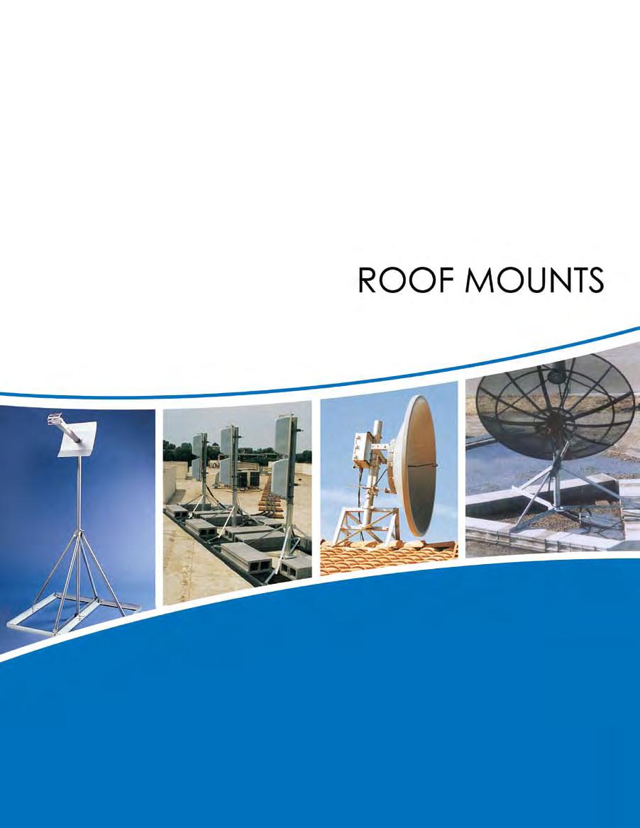
2 RM ROOF MOUNTS EFFECTIVE WIND VELOCITY FORMULA SHEET ROHN recommends a minimum mph Effective Wind be used for determining ballast requirements. Refer to page 2 for ballast requirements and general notes. V = (C1) (C2) (V) e V e = Effective Wind at centerline of antenna for calculating required ballast. C1 = Importance factor coefficient from Table 1. C2 = Combined exposure and gust effect factor coefficient from Table 2. V = Design ground wind speed for location, per ANSI/TIA-222-G. Table 1: Values of C1 Roof Height Class Description for installing considering height, use or location <_ ft. > ft. I Low hazard to human life and/or damage to property, optional services provided II Significant hazard to human life and/or damage to property, services available by other means III Substantial hazard to human life and/or damage to property, essential services provided Exposure B C D 2 Description of Surrounding Terrain Urban and suburban areas, wooded areas, or other terrain with numerous closely spaced obstructions having the size of single-family dwellings or larger. Open terrain with scattered obstructions having heights generally less than 30 [9.1m], including flat, open country and grasslands. Flat, unobstructed shorelines exposed to wind flowing over open water, smooth mud flats, salt flats, and other similar terrain. Example: 30 antenna elevation, mph design ground wind speed, Class I, Exposure B V e = (1.29) (0.) () = mph The minimum Effective Wind for determining ballast requirements for this example would be mph. This data sheet is provided to assist consumers in determining the minimum Effective Wind to be used for determining ballast requirements from a ROHN Non-Penetrating Roof Mount Chart. Higher velocities may be required for sites located on hills, escarpments or ridges (refer to ANSI/TIA-222-G). Potential increases in wind velocity due to channeling, roof projections and other obstructions must also be considered. The information shown should not be relied upon without competent professional examination and verification of its accuracy and suitability for a specific site or application. Antenna Centerline Elevation Above Ground Level (ft.) Phone (309) 6- Fax (309) The Industry Standard Table 2: Values of C2 Exposure B C D Urban or Wooded Open Country Areas & Grasslands Open Water or Smooth Terrain
3 ROOF MOUNTS - FRM RM FRM NON-PENETRATING The FRM mount is a lightweight mount and is galvanized for corrosion protection. The FRM mount is easily shipped via UPS. Order (1) optional FRMMAT (1/8 thick) or (1) optional FRMPAD (3/8 thick) for a protective barrier between the mount and the roof. Order (1) optional SCK1 safety cable kit (3/16 x 1 ) to 2. Mast Tube Diameters 2.5 and 5 Overall Mast Heights (See Mast Descriptions) 16 Nominal Blocks 3 Square Mount Part No. FRM FRM1 FRM1 FRM2 FRM225 FRM2SP5 MAST SPECIFICATIONS Mast Part No. Mast Description & Height FY O.D. x 16 GA. x (PG) FY O.D. x 16 GA. x 2.5 (PG) FY O.D. x 16 GA. x 2.5 (PG) FY O.D. x 0.1 wall x 2.5 (HDG) FY205SP 2.25 O.D. x 14 GA. x (HDG) FY2 2. O.D. x 0.1 wall x (HDG) PG = Pre-galvanized mast HDG = Hot-dip galvanized mast Effective Projected Area (EPA) (FT 2) FRM BALLAST REQUIREMENTS Vs Phone (309) 6- Fax (309) The Industry Standard Vmax at centroid of projected area, h=2 FT h=3 FT h=4 FT h=5 FT (1) 1 (139) () 1 (1) 1 (1) 134() () () () 1 () () () () () h = Distance from support surface to centroid of EPA. Vs = Effective wind velocity resulting in sliding on a flat surface with a. coefficient of friction. Vmax = Effective wind velocity based on strength or overturning. NOTE: The velocities in ( ) apply to the FRM mount when the strength of the FRM mast governs. 2
4 RM ROOF MOUNTS - JRM JRM NON-PENETRATING The JRM ships broken down on one skid and weighs approximately lbs. when assembled. The JRM is galvanized for corrosion protection. The JRM is used in cellular, PCS, broadband and other applications. Order (1) optional JRMMAT (1/8 thick) or (1) optional JRMPAD (3/8 thick) for a protective barrier between the mount and the roof. Order (1) optional SCK1 safety cable kit (3/16 x 1 ). Refer to pages 2-2 for ballast requirements. 2. to 3. Mast Tube Diameters, 1 and 2 piece options 5 or 10 (1 & 2 piece) Overall Mast Heights (See Mast Descriptions) 16 Nominal Blocks 5 Square 2 Mount Part No. JRM235 JRM235 JRM230 JRM205 JRM2 JRM210 JRM310 MAST SPECIFICATIONS Mast Part No. Mast Description & Height FZ15 2. O.D. x 0.1 wall x (HDG) (1 piece) FZ13 / FZ14 2. O.D. x 0.1 wall x (HDG) (2 pieces) FZ16 2. O.D. x 0.1 wall x (HDG) (1 piece) FZ17 2. O.D. x wall x (HDG) (1 piece) FZ18 / FZ19 2. O.D. x wall x (HDG) (2 pieces) FZ10 2. O.D. x wall x (HDG) (1 piece) FZ11 3. O.D. x wall x (HDG) (1 piece) HDG = Hot-dip galvanized mast Phone (309) 6- Fax (309) The Industry Standard
5 Effective Projected Area (EPA) (FT 2) h = Distance from support surface to centroid of EPA JRM BALLAST REQUIREMENTS Vs ROOF MOUNTS - JRM Vmax at centroid of projected area, h=2 FT h=3 FT h=4 FT h=5 FT h=6 FT h=7 FT h=8 FT h=9 FT Vmax = Effective wind velocity based Phone (309) 6- Fax (309) The Industry Standard on strength or overturning. NOTE: Mast strength may govern antenna capacity. 1 1 Vs = Effective wind velocity resulting in sliding on a flat surface with a. coefficient of friction. RM 2
6 RM ROOF MOUNTS - JRM 2 Effective Projected Area (EPA) (FT 2) h = Distance from support surface to centroid of EPA JRM BALLAST REQUIREMENTS Vs 1 Vmax at centroid of projected area, h=2 FT h=3 FT h=4 FT h=5 FT h=6 FT h=7 FT h=8 FT h=9 FT Vmax = Effective wind velocity based Phone (309) 6- Fax (309) The Industry Standard on strength or overturning. NOTE: Mast strength may govern antenna capacity Vs = Effective wind velocity resulting in sliding on a flat surface with a. coefficient of friction.
 optional BRM4MAT (1/8 thick) or (1) optional BRM4PAD (3/8 thick) for a protective barrier between the mount and the roof. Order (1) optional SCK1 safety cable kit (3/16 x 1 ).")
7 ROOF MOUNTS - BRM4 RM BRM4 NON-PENETRATING The BRM4 mount is hot-dip galvanized after fabrication for corrosion protection. Order (1) optional BRM4MAT (1/8 thick) or (1) optional BRM4PAD (3/8 thick) for a protective barrier between the mount and the roof. Order (1) optional SCK1 safety cable kit (3/16 x 1 ). Refer to pages 2-2 for ballast requirements. 2. to 5. Mast Tube Diameters 3 and 10 Overall Mast Heights (See Mast Descriptions) 16 Nominal Blocks 6.5 Square MAST SPECIFICATIONS Mount Part No. BRM425 BRM0 BRM5 BRM0 BRM5 BRM4 BRM420 BRM0 BRM0 Mast Part No. KY15 KY15 KY15 KY15 KY15 KY10 KY20 KY20 KY20 Mast Description & Height 2. O.D. x 0.1 wall x O.D. x wall x O.D. x wall x O.D. x wall x O.D. x wall x O.D. x 0.2 wall x O.D. x 0.1 wall x 3. O.D. x wall x 4. O.D. x wall x Phone (309) 6- Fax (309) The Industry Standard 2
8 RM 2 ROOF MOUNTS - BRM4 Effective Projected Area (EPA) (FT 2) h = Distance from support surface to centroid of EPA BRM4 BALLAST REQUIREMENTS Vs Vmax at centroid of projected area, h=2 FT h=3 FT h=4 FT h=5 FT h=6 FT h=7 FT h=8 FT h=9 FT Vmax = Effective wind velocity based on strength or overturning. Phone (309) 6- Fax (309) The Industry Standard NOTE: Mast strength may govern antenna capacity Vs = Effective wind velocity resulting in sliding on a flat surface with a. coefficient of friction.
9 Effective Projected Area (EPA) (FT 2) h = Distance from support surface to centroid of EPA BRM4 BALLAST REQUIREMENTS Vs ROOF MOUNTS - BRM4 Vmax at centroid of projected area, h=2 FT h=3 FT h=4 FT h=5 FT h=6 FT h=7 FT h=8 FT h=9 FT Phone (309) 6- Fax (309) The Industry Standard Vmax = Effective wind velocity based on strength or overturning NOTE: Mast strength may govern antenna capacity Vs = Effective wind velocity resulting in sliding on a flat surface with a. coefficient of friction. RM 2
 optional BRM6MAT (1/8 thick) or (1) optional BRM6PAD (3/8 thick) for a protective barrier between the mount and the roof. Order (1) optional SCK1 safety cable kit (3/16 x 1 ).")
10 RM ROOF MOUNTS - BRM6 BRM6 NON-PENETRATING The BRM6 mount is hot-dip galvanized after fabrication for corrosion protection. Order (1) optional BRM6MAT (1/8 thick) or (1) optional BRM6PAD (3/8 thick) for a protective barrier between the mount and the roof. Order (1) optional SCK1 safety cable kit (3/16 x 1 ). Optional additional inner ballast support angle kit available, order P/N BRM6ABK. Refer to pages 2-2 for ballast requirements. 2. to 6. Mast Tube Diameters 4 and 10 Overall Mast Heights (See Mast Descriptions) 16 Nominal Blocks 10 Square MAST SPECIFICATIONS Mount Part No. BRM0M BRM5M BRM0M BRM5M BRM5M BRM6M BRM0M Mast Part No. KY2 KY15 KY15 KY15 KY15 KY15 KY20 Mast Description & Height 2. O.D. x wall x O.D. x wall x O.D. x wall x O.D. x wall x O.D. x 0.2 wall x O.D. x 0.2 wall x O.D. x wall x 2 Phone (309) 6- Fax (309) The Industry Standard
11 ROOF MOUNTS - BRM6 RM BRM6 4 FT. DISH ELEVATION BALLAST REQUIREMENTS Dish Diameter 4 (1.2 m) Design Wind Velocities EL=0º EL=20º EL=40º Vmax Vs Vmax Vs Vmax Vs (1.8 m) (2.4 m) EL = Dish antenna azimuth angle with horizontal. Vmax = Effective wind velocity based on strength or overturning. Vs = Effective wind velocity resulting in sliding on a flat surface with a. coefficient of friction. NOTE: Mast strength may govern antenna capacity. Phone (309) 6- Fax (309) The Industry Standard 2
12 RM ROOF MOUNTS - BRM6 2 Effective Projected Area (EPA) (FT 2) EL = Dish antenna angle with horizontal. BRM6 BALLAST REQUIREMENTS Vs Vmax at centroid of projected area, h=4 FT h=5 FT h=6 FT h=7 FT h=8 FT h=9 FT h=10 FT Vmax = Effective wind velocity based on strength or overturning. Phone (309) 6- Fax (309) The Industry Standard NOTE: Mast strength may govern antenna capacity Vs = Effective wind velocity resulting in sliding on a flat surface with a. coefficient of friction.
13 ROOF MOUNTS - BRM6 RM BRM6 BALLAST REQUIREMENTS Effective Projected Area (EPA) (FT 2) Vs Vmax at centroid of projected area, h=4 FT h=5 FT h=6 FT h=7 FT h=8 FT h=9 FT h=10 FT EL = Dish antenna angle with horizontal. Vmax = Effective wind velocity based on strength or overturning. Vs = Effective wind velocity resulting in sliding on a flat surface with a. coefficient of friction. NOTE: Mast strength may govern antenna capacity. Phone (309) 6- Fax (309) The Industry Standard 2

14 RM ROOF MOUNTS - NPPK NPPK NON-PENETRATING The NPPK mount is a great solution for broadband antennas and satellite TV dishes. The adjustable mounting plate can be center mounted or to one side as needed to accommodate other satellite TV dish mounts. Our 1LG mount (located on page 2) with a base and 1-1/4 mounting tube can be attached to the NPPK. The mount comes standard with double ballast trays on each side to hold concrete blocks. The NPPK mount is hot-dip galvanized after fabrication for corrosion protection. Order (2) optional FRMMAT (1/8 thick) or (2) optional FRMPAD (3/8 thick) for a protective barrier between the mount and the roof. Order (1) optional SCK1 safety cable kit (3/16 x 1 ). Adjustable Mounting Plate Nominal Blocks Mount Adjusts to Roof Angle 3 2 Phone (309) 6- Fax (309) The Industry Standard

15 ROOF MOUNTS - 25GBRM RM 25GBRM NON-PENETRATING The 25GBRM mount is designed to support one or two 25G tower sections in a self-supporting application. The 25GBRM mount is galvanized after fabrication for corrosion protection. Order (1) optional BRM6MAT (1/8 thick) or (1) optional BRM6PAD (3/8 thick) for a protective barrier between the mount and the roof. Order (1) optional SCK1 safety cable kit (3/16 x 1 ). Refer to page 2 for ballast requirements. Overall Mast Heights (1) 25G Section (2) 25G Sections Standard 25G sections mount to top of 25GBRM 16 Nominal Blocks 10 Square Phone (309) 6- Fax (309) The Industry Standard 2
16 RM ROOF MOUNTS - 25GBRM 25GBRM BALLAST REQUIREMENTS Effective Projected Area (EPA) (FT 2) Vs One Section h=12.4 FT Vs Two Sections h=22.4 FT 1 Section Vmax at centroid of projected area, h=12.4 FT 2 h=22.4 Sections FT Effective Projected Area (EPA) (FT 2) Vs One Section h=12.4 FT Vs Two Sections h=22.4 FT 1 Section Vmax at centroid of projected area, h=12.4 FT 2 h=22.4 Sections FT h = Distance from support surface to centroid of EPA. Vs = Effective wind velocity resulting in sliding on a flat surface with a. coefficient of friction. Vmax = Effective wind velocity based on strength or overturning Phone (309) 6- Fax (309) The Industry Standard
 optional AGMMAT (1/8 thick) or (1) optional AGMPAD (3/8 thick) for a protective barrier between the mount and the roof. Order (1) optional SCK1 safety cable kit (3/16 x 1 ).")
17 ROOF MOUNTS - AAGM RM AAGM NON-PENETRATING The AAGM mount is capable of supporting dishes with diameters up to 10 feet. The AAGM mount is hot-dip galvanized after fabrication for corrosion protection. Order (1) optional AGMMAT (1/8 thick) or (1) optional AGMPAD (3/8 thick) for a protective barrier between the mount and the roof. Order (1) optional SCK1 safety cable kit (3/16 x 1 ). Refer to page 2 for ballast requirements. 3. to 6. Mast Tube Diameters 2.5 and 5 Overall Mast Heights (See Mast Descriptions) Nominal Blocks 16.3 Mount Part No. AAGM35 AAGM40 AAGM45 AAGM AAGM MAST SPECIFICATIONS Mast Part No. FYS FYS FYS FYS FYS Mast Description & Height 3. O.D. x wall x O.D. x wall x O.D. x wall x O.D. x 0.2 wall x O.D. x 0.2 wall x Phone (309) 6- Fax (309) The Industry Standard 2
18 RM ROOF MOUNTS - AAGM AAGM 4.5 FT DISH ELEVATION BALLAST REQUIREMENTS Dish Diameter Vmax Vs EL=0º EL=20º EL=40º 4 (1.2 m) (1.8 m) (2.4 m) (3.0 m) EL = Dish antenna azimuth angle with horizontal. Vmax = Effective wind velocity based on strength or overturning. Vs = Effective wind velocity resulting in sliding on a flat surface with a. coefficient of friction. NOTE: Mast strength may govern antenna capacity. 2 Phone (309) 6- Fax (309) The Industry Standard
 optional PRM6MAT (1/8 thick) or (1) optional PRM6PAD (3/8 thick) for a protective barrier between the mount and the roof.")
19 ROOF MOUNTS - PRM6 RM PRM6 NON-PENETRATING The PRM6 mount is capable of supporting dishes with diameters up to 6 feet. The mount is hot-dip galvanized after fabrication for corrosion protection. Th PRM6 mount is also UPS shippable. Order (1) optional PRM6MAT (1/8 thick) or (1) optional PRM6PAD (3/8 thick) for a protective barrier between the mount and the roof. Order (1) optional SCK1 safety cable kit (3/16 x 1 ). 3. to 5. Mast Tube Diameters Overall Mast Heights (See Mast Descriptions) Concrete blocks not provided with mount Dish Diameter 4 (1.2 m) 6 (1.8 m) BALLAST REQUIREMENTS Design Wind Velocities EL=0º EL=20º EL=40º Vmax Vs Vmax Vs Vmax Vs Mount Part No. PRM5 PRM0 PRM5 PRM5 MAST SPECIFICATIONS Mast Part No. Mast Description KY16 3. O.D. x wall KY O.D. x wall KY16 4. O.D. x wall KY16 5. O.D. x 0.2 wall Phone (309) 6- Fax (309) The Industry Standard 2.4 EL = Dish antenna azimuth angle with horizontal. Vmax = Effective wind velocity based on strength or overturning. Post Tensioning Rods (TYP) Vs = Effective wind velocity resulting in sliding on a flat surface with a. coefficient of friction. NOTE: Mast strength may govern antenna capacity. 2
20 RM ROOF MOUNTS BALLAST REQUIREMENTS FOR ROOF MOUNTS 1. requirements are provided to assist consumers in determining the applicability of a non-penetrating roof mount for an antenna installation and to assist in determining the amount of ballast required. The ballast requirements should not be relied upon without competent local professional examination and verification of its accuracy and suitability for a specific site or application. 2. Specific antennas and/or other mounting configurations may require more stringent strength and ballast requirements and must be investigated for each installation. The load carrying requirements of the supporting surface, the mount and mast, the antenna and the antenna s connection to the mast must be investigated for each installation. 3. When antenna areas are indicated vs. specific antenna types, the areas tabulated are effective projected areas that include appropriate wind drag factors applied to the projected areas of the supported antennas and the exposed portions of the mount and ballast. The center of the effective projected area is assumed to be at the top of the mounting pipe or the height indicated in the ballast table. Unless otherwise indicated, tabulated ballast requirements assume that the effective projected areas are concentric to the mount and that uplift or download wind forces are insignificant. 4. The tabulated wind velocities are considered to occur at the centroid of the effective projected areas. The wind velocity appropriate for an installation must be determined on an individual site basis considering the location and elevation of the mount. The wind velocity at ground level must be multiplied by appropriate height escalation and gust factors. Potential increases in wind velocity due to channeling, roof projections, and other obstructions, must also be considered when determining ballast requirements. 5. The ballast weights indicated are assumed to be uniformly distributed on the mount. The weight of the mount and antenna may be considered as ballast. Mounts are assumed to be mounted on a flat supporting surface. 6. The zero velocity loads shown are equal to the tabulated ballast weights divided by the total area enclosed by the perimeter of the mount. This area is greater than the ballast contact area. s which must be investigated include reactions caused by wind forces and moments, live loads, ice loads, earthquake loads and the dead loads of ballast, mount, antenna, mounting hardware, miscellaneous equipment and roof pads. 7. The tabulated maximum wind velocities (Vmax) are based on a minimum 1.5 factor of safety against structural failure and overturning. 8. The tabulated wind velocities resulting in sliding (Vs) are based on a factor of safety equal to 1.0 and an effective coefficient of friction equal to 0. between the mount and a flat supporting surface. A 1.0 factor of safety was used assuming that at higher wind velocities, safety cables or other suitable attachments to the support structure would prevent sliding beyond a safe, designated area. 9. The appropriate coefficient of friction and factor of safety to determine wind velocities resulting in sliding must be determined on an individual site basis. The coefficient of friction may vary under changing moisture and temperature conditions. The minimum coefficient of friction must be used to evaluate sliding resistance. Wind speeds resulting in sliding for other factors of safety or for other coefficients of friction may be found by multiplying the tabulated values of Vs by the following modification factor: Modification Factor = [µ /(.5 x FS)] 1/2 µ= Coefficient of Friction FS = Factor of Safety 10. The values of Vs indicated do not apply for installations which are prevented from sliding by cables or other suitable attachments to the supporting structure. 11. Roof pads are recommended to prevent damage to roof membranes. Pads should be placed under all contact areas. 12. ROHN recommends that ballast material always be placed prior to mounting the antenna and that roof pads and mount be secured to prevent hazards from occurring under extreme wind loading conditions. Precautions should also be taken to prevent the inadvertent removal of ballast material after installation and to insure that all ballast material is fully supported by the mount (required for ballast to be effective in resisting overturning and sliding). 13. When adhesives are used to secure roof pads, the adhesive must be compatible with the supporting surface. Precautions should be taken to insure that damage to the supporting surface will not occur upon wind loading. 14. The installation, roof material and supporting structure must be capable of withstanding all loads imposed by the antenna system. Supporting surfaces, anchors and/or safety cables must be sufficient to resist the reactions from the antenna system. The installation must meet all applicable local, state and federal requirements. 2 Phone (309) 6- Fax (309) The Industry Standard

21 ROOF MOUNTS - URM RM URM ROHN s Universal Roof Mount (URM) is capable of supporting most PCS, Cellular, and Microwave antennas. The URM adapts to various roof pitches and the fully adjustable rear-leg allows for use on a flat or up to a 12 /12 pitched roof. Installation is easy because of the quick adaptability, plus there s no need for concrete blocks. The URM is hot-dip galvanized after fabrication for corrosion protection, and can easily ship UPS. 25 Optional Masts - Ordered Separately P20 2. O.D. x wall x 30 Long P O.D. x wall x 30 Long P O.D. x wall x 30 Long P0 4. O.D. x wall x 30 Long Braces provided with multiple holes to allow + / - 26 of length adjustment Features: 1. URM mount can be used on a flat roof, sloped roof or over a roof peak. 2. URM mount can be used with 2. to 4. O.D. masts (order separately). 3. Bottom of mount pivots to match roof pitch. 4. Rear leg adjusts for extra length. 5. Mount base angles are pre-drilled to accept 1/2 diameter connectors. Phone (309) 6- Fax (309) The Industry Standard 2

22 RM ROOF MOUNTS - SHRM SHRM ROHN s Saw Horse Roof Mount (SHRM) is capable of supporting most PCS, Cellular, and Microwave antennas. The SHRM allows for placement of antennas on flat roofs or roof peaks with up to a 12 /12 pitch. The SHRM is also able to be installed on flat roofs. Installation is easy because of the quick adaptability, plus there s no need for concrete blocks. The SHRM is hot-dip galvanized after fabrication for corrosion protection, and can easily ship UPS. 28 Optional Masts - Ordered Separately P20 2. O.D. x wall x 30 Long P O.D. x wall x 30 Long P O.D. x wall x 30 Long P0 4. O.D. x wall x 30 Long Features: 1. SHRM mount can be used on a flat roof or on a roof peak, up to 45 degrees maximum pitch. 2. SHRM mount can be used with 2. to 0 O.D. masts (ordered separately). 3. Bottom of mount pivots to match roof pitch. 4. Mount base angles are pre-drilled to accept 1/2 diameter connectors. 2 Phone (309) 6- Fax (309) The Industry Standard
.")

 5 tall, tube legs (PG) 5 tall, angle legs (HDG) with 2. O.D. x 0.1 wall x 3.")
23 ROOF MOUNTS - TRT RM TRT36 / TRT / TRTAG2 The TRT is a Tripod Roof Tower, which comes fully assembled and snaps out into position for quick installation using up to 1/4 dia. connectors. The TRTAG2 mount comes with a 2 3/8 O.D. hot-dip galvanized mast, the TRT36 and TRT mounts accept masts up to 1 3/4 O.D. (ordered separately). The bolt-on swivel feet adjust to most any pitch roof. TRT mounts are galvanized for corrosion protection. All TRT mounts are UPS shippable. Angle leg Mast TRTAG2 comes with a 2 3/8 O.D. mast. Masts must be ordered separately for the TRT36 and TRT. Please see page 301 for mast options. TRTAG2 Tube leg TRT36 and TRT fit ROHN s Telescoping masts (see pages 2-2). TRT TRT36 SPECIFICATIONS Part No. TRT36 TRT TRTAG2 Description 3 tall, tube legs (PG) 5 tall, tube legs (PG) 5 tall, angle legs (HDG) with 2. O.D. x 0.1 wall x 3.5 long mast (HDG) PG = Pre-galvanized HDG = Hot-dip galvanized Phone (309) 6- Fax (309) The Industry Standard 2
EFFECTIVE WIND VELOCITY FORMULA SHEET
 ROOF MOUNTS EFFECTIVE WIND VELOCITY FOULA SHEET ROHN recommends a minimum mph Effective Wind be used for determining ballast requirements. V = C1 C2 V e V e = Effective Wind at centerline of antenna for
Non Penetrating Mast Mount for 2.4M Antennas
 April 27, 2007 INSTALLATION MANUAL Non Penetrating Mast Mount for 2.4M Antennas GENERAL DYNAMICS PRODELIN CORPORATION 1500 Prodelin Drive Newton NC 28658USA Phone 828-464-4141 www.gdsatcom.com Non-Penetrating
6-1/2 FT. x 6-1/2 FT. NON-PENETRATING MAST MOUNT
 4096-349 March 27, 2012 REVISION J ASSEMBLY MANUAL 6-1/2 FT. x 6-1/2 FT. NON-PENETRATING MAST MOUNT General Dynamics 1500 PRODELIN DRIVE NEWTON, NC 28658 INSTALLATION INSTRUCTIONS J Revised tool list,
10 X 10 NPMM Installation
 May 20, 2016 Revision E ASSEMBLY MANUAL Installation General Dynamics SATCOM Technologies 1700 Cable Drive NE Conover NC 28613 USA Phone 770-689-2040 www.gdsatcom.com 10' x 10' NPMM INSTALLATION INSTRUCTIONS
ANTENNA SUPPORT STRUCTURES
 14.1 Rooftop Ballast Frame for Wireless Antennas General Description Non-penetrating Rooftop Ballast Frames enable installation of wireless panel antennas for a sector. The Frames are secured using concrete-block
Table of Contents. Kit Maximum Examples Index by Kit Number Terms and Conditions...Inside Back Cover
 Table of Contents Antenna Mounts Light Standoff Mounts...2 Medium Standoff Mounts...4 Heavy Standoff Mounts...6 Fixed Crossover Assemblies...8 Universal Crossover Assemblies...8 Hybrid Crossover Assemblies...9
2009 ROHN PRODUCTS LLC
 2009 ROHN PRODUCTS LLC G U Y E D T O W E R S S T A N D A R D 2 5 G G U Y E D T O W E R GENERAL USE The is available in the standard 0 section length and a 7 length which is UPS shippable. The uses double
STANDARD 80 SERIES GUYED TOWER GENERAL USE FEATURES. Phone (309) Fax (309) The Industry Standard
 Fax (309) The Industry Standard") G GUYED TOWERS - 80 STANDARD 80 SERIES GUYED TOWER 80 SERIES GENERAL USE The ROHN Model 80 Guyed Tower is designed with variable sized legs and braces to allow construction to heights of 1000. This tower
G GUYED TOWERS - 80 STANDARD 80 SERIES GUYED TOWER 80 SERIES GENERAL USE The ROHN Model 80 Guyed Tower is designed with variable sized legs and braces to allow construction to heights of 1000. This tower
STANDARD 25G GUYED TOWER. includes REV. F & REV. G GENERAL USE FEATURES. Phone (309) Fax (309) The Industry Standard
 Fax (309) The Industry Standard") G GUYED TOWERS 25G STANDARD 25G GUYED TOWER ROHN 25G The first. The original. includes REV. F & REV. G 25G GENERAL USE The 25G is available in the standard 0 section length and a 7 length which is UPS
G GUYED TOWERS 25G STANDARD 25G GUYED TOWER ROHN 25G The first. The original. includes REV. F & REV. G 25G GENERAL USE The 25G is available in the standard 0 section length and a 7 length which is UPS
Model m x 1.6 m NPRM with Roof Pads For 96 cm, 1.0 m and 1.2 m Antenna Systems
 Installation Instructions 8000839-02 Model 60063-04.6 m x.6 m NPRM with Roof Pads For 96 cm,.0 m and.2 m Antenna Systems Skyware Global 35 Industrial Park Drive Smithfield, NC 27577 USA Telephone: +-99-934-97
2.88 OD Universal Mast Mount
 Revision A January 19, 2006 ASSEMBLY MANUAL 2.88 OD Universal Mast Mount GENERAL DYNAMICS PRODELIN CORPORATION 1500 Prodelin Drive Newton NC 28658USA Phone 828-464-4141 www.gdsatcom.com 2.88 O.D. Universal
SITE ACCESSORIES CATALOG USA.
 SITE ACCESSORIES CATALOG USA 2019 www.trylon.com Pictorial Table of Contents Page 2 Sector V-Frames Page 4 RRU Mounts Page 5 Rotatable Standoff Mounts Page 6 Light Standoff Mounts Page 8 Medium Standoff
INTRODUCTION. Sincerely, Dan Ianello, PE President. Toll Free: NELLO Fax:
 INTRODUCTION Nello Corporation specializes in the Communications Support Infrastructure market. We have a strategy of providing innovative and cost effective products to an industry that relies on quality,
BAIRD Wall Mounting System WL-2(23")
") BAIRD Wall Mounting System WL-2(23") The WL-2(23") Wall Mounting System is engineered to handle up to and including a 10' (3.0M) antenna. The WL-2(23") has a 23" offset from the wall to the mast. The customer
BAIRD Wall Mounting System WL-2(23") The WL-2(23") Wall Mounting System is engineered to handle up to and including a 10' (3.0M) antenna. The WL-2(23") has a 23" offset from the wall to the mast. The customer
WIND MAP. United States
 Special Wind Region (Consult Local Authorities) LOCATION V mph (m/s) Hawaii 105 (47) Puerto Rico 145 (65) Guam 170 (76) Virgin Islands 145 (65) American Samoa 125 (56) Notes: 1. Values are nominal design
Structural Support Products. Wireless Site Solutions Ordering Guide Version 2.1
 Structural Support Products Wireless Site Solutions Ordering Guide Version 2.1 TOWER MOUNTS G2 Series High Capacity Sector Frames Quick-Vee Medium Capacity Sector Frames Sector Frame Reinforcement Kits
Steel Products. Microwave Planners Guide. Structural Support Products. Midwest Underground Technology, Inc.
 Steel Products Microwave Planners Guide Structural Support Products Midwest Underground Technology, Inc. MUTI AND COMMSCOPE MUTI and Commscope have joined forces to address client concerns on the installation
TO BE USED FOR MAINTENANCE MICHIGAN DEPARTMENT OF TRANSPORTATION. 2 3/16" x 2 3/16" x 10 Ga. 12" 15.5" 1 1/2" x 1 1/2" x 12 Ga.
 2 3/16" x 2 3/16" x 10 Ga. TOP VIEW 18" 1" 7/16" Hole 1 1/2" x 1 1/2" x 12 Ga. two sides only steel tubing 1 1/2" x 1 1/2" x 12 Ga. @ 18" long steel angle 15.5" 12" TRAFFIC 3/8" Hex head grade 5 steel
LMS 106 CR MODEL MOBILE TOWER
 LMS 106 CR MODEL MOBILE TOWER 106 TALL, 6 EA SECTIONS LEGS ASTM A500-07, A53-12, GRADE B, US CARBON STEEL Lifetime Warranty TILT BASE ASSEMBLY INTEGRATED INTO TRAILER. Lifetime Warranty 3 SECTOR ANTENNA
WESTERN SPECIFIER. Technical Data for PWI Joists, PWLVL Headers, Beams, Rim Board, Stud, and Dimension
 E N G I N E E R E D W O O D WESTERN SPECIFIER Technical Data for PWI Joists, PWLVL Headers, Beams, Rim Board, Stud, and Dimension P R O D U C T S JOIST DIMENSIONS 9½ LVL FLANGE PWI JOIST SERIES JOIST DIMENSIONS
ROOFING SOLUTIONS DESIGN GUIDE PURLINS AND GIRTS DESIGN GUIDE PURLINS AND GIRTS S&T029N
 DESIGN GUIDE PURLINS AND GIRTS ROOFING SOLUTIONS DESIGN GUIDE PURLINS AND GIRTS S&T029N JUL 2015 CONTENTS INTRODUCTION 2 Acknowledgements 2 Disclaimer 2 Product Technical Statement 3 Producer Statement
KRANE-KING Jib & Gantry Cranes Gantries Free Standing Jibs Tension & Cantilevered Jibs Hoists
 KRANE-KING Jib & Gantry Cranes Gantries Pages H.4 - H.17 Free Standing Jibs Pages H.18 - H.30 Tension & Cantilevered Jibs Pages H.31 - H.35 Hoists Pages H.36 - H.42 Index to Krane-King Jib & Gantry Cranes
Saf-T Vent EZ Seal. Technical and Dimensional Data. Single Wall AL 29-4C Stainless Steel Special Gas Vent
 Technical and Dimensional Data Saf-T Vent EZ Seal Single Wall AL 29-4C Stainless Steel Special Gas Vent 130 Industrial Boulevard Turners Falls, MA 01376 Copyright 2001 Heat-fab, Incorporated Saf-T Vent
Transmission Line Support Systems
 Coax Bridge Kit Each Coax Bridge Kit provides rooftop support for coax transmission lines on three PVC sleepers and protects the coax from damage with an long steel cover. The three series of products
LMS 120 XHD MODEL MOBILE TOWER
 LMS 120 XHD MODEL MOBILE TOWER MOBILE TOWER 120 TALL, 6 EA SECTION LEGS ASTM A500-07, A53-12, GRADE B, US CARBON STEEL Lifetime Warranty TILT BASE ASSEMBLY INTEGRATED INTO TRAILER. Lifetime Warranty 3
Operation and Maintenance Manual. for Fiberglass Tanks
 Operation and Maintenance Manual for Fiberglass Tanks Perry Fiberglass Products, Inc. HANDLING AND INSTALLATION INSTRUCTIONS ABOVE GROUND STORAGE TANKS The following handling and installation instructions
Allowable Holes in VERSA-LAM Beams
 VERSA-LAM Products 23 An Introduction to VERSA-LAM Products When you specify VERSA-LAM laminated veneer headers/beams, you are building quality into your design. They are excel lent as floor and roof framing
panelclaw.com Polar Bear III for 10 Degree
 panelclaw.com Polar Bear III for 10 Degree Installation Manual Document Number 9910024 Rev A March 2014 Revision History Rev ECO # Date Description of Changes Approved By 01 TBD 02-FEB-14 Initial Draft
ARCHITECTURAL ROOF SUPPORTS
 SECTION E ARCHITECTURAL A-0 ARCHITECTURAL TABLE OF CONTENTS Thaler Or Equal ARS-100A Floating Walkway Roof Support ARS-102A Fire Route Walkway Roof Supports ARS-115 Rail Post Roof Supports ARS-122 Satellite
PRODUCTS FOR PV SOLAR MOUNTING APPLICATIONS ROOF MOUNT SYSTEMS...3. GROUND and pole MOUNT SYSTEMS...5. L Feet...9. Corrugated/IBR Roof Mounts...
 S 1 Index PRODUCTS FOR PV SOLAR MOUNTING APPLICATIONS ROOF MOUNT SYSTEMS...3 GROUND and pole MOUNT SYSTEMS...5 Power Rail Module Mounting System...6 Power Rail Extrusions...7 Power Rail Commercial Extrusions...7
LONG LENGTH DESIGN MANUAL CONTENTS PAGE. Introduction Long Length features & benefits... 2 Long Length belting programme... 7
 DESIGN MANUAL LONG CONTENTS PAGE LENGTH Introduction Long Length features & benefits... 2 Long Length belting programme... 7 Drive Design Belt drive selection procedure... 8 Belt pitch selection guides...
VENT SILENCER PRODUCT GUIDE
 VENT SILENCER Copyright 200 by PULSCO Incorporated. All rights reserved. Reproduction without permission is prohibited. PRODUCT GUIDE PULSCO VENT SILENCER TABLE OF CONTENTS DESCRIPTION PAGE PULSCO VENT
STREAMLINED SOLAR CHECKLIST Owner Name:
 STREAMLINED SOLAR CHECKLIST Owner Name: Address: DEPARTMENT OF PUBLIC WORKS AND PLANNING ALAN WEAVER, DIRECTOR This checklist must be completed by the contractor or an authorized agent of the contractor
DELINEATOR REFERENCE POINT 200' TYPICAL SPACING (YELLOW DELINEATORS) END OF MERGE LANE TAPER DELINEATOR REFERENCE POINT
 END OF MERGE LANE TAPER DELINEATOR REFERENCE POINT") 200' TYP. 0' < EACH SIDE BOTH ROADWAYS END OF MERGE LANE TAPER TYPICAL FOR ALL 2-LANE MERGES EXCEPT WHERE THERE IS A MERGE FROM THE RIGHT AND NO OFFSET IN THE THROUGH LANES END OF MERGE LANE TAPER 200'
200' TYP. 0' < EACH SIDE BOTH ROADWAYS END OF MERGE LANE TAPER TYPICAL FOR ALL 2-LANE MERGES EXCEPT WHERE THERE IS A MERGE FROM THE RIGHT AND NO OFFSET IN THE THROUGH LANES END OF MERGE LANE TAPER 200'
SECTION LIFT ARM PARKING GATES
 St. Anthony of Padua Catholic Church Phase I The Woodlands, Texas JRA Proj. No. 15004 Issued for Bidding - 1/20/2016 SECTION 11 12 33.13 LIFT ARM PARKING GATES PART 1 - GENERAL 1.01 SUMMARY A. Section
western for products manufactured in White City, Oregon
 western VERSA-LAM SPECIFIER Guide for products manufactured in White City, Oregon Western VERSA-LAM Guide 11/29/2012 2 VERSA-LAM Products An Introduction to VERSA-LAM Products When you specify VERSA-LAM
INSTRUCTION MANUAL_. Specifications. Electrical.
 308 Industrial Park Road Starkville, MS 39759 USA Ph: (662) 323-9538 FAX: (662) 323-6551 DX-77A 7-Band HF Vertical 10, 12, 15, 17, 20, 30, 40-Meter INSTRUCTION MANUAL_ General Description The "DX-77-A"
90CM KA-BAND TYPE 9013 ANTENNA SYSTEM with Factory Assembled Az/El Mount
 MARCH 2017 Revision A ASSEMBLY MANUAL 8001121-01 90CM KA-BAND TYPE 9013 ANTENNA SYSTEM with Factory Assembled Az/El Mount A ORIGINAL RELEASE MAR 2017 R. Thompson REV. DESCRIPTION DATE APPROVED Global Skyware
LSU University Safety Manual Section IV, Part C Stairs and Ladders. C. Stairs & Ladders
 C. Stairs & Ladders 1. General Requirements a. A stairway or ladder must be provided at all worker points of access where there is a break in elevation of 19 inches (48 cm) or more and no ramp, runway,
Installation Guide. PV Booster Single Axis Tracker. Mechanical Roof Attachment.
 Installation Guide PV Booster Single Axis Tracker Mechanical Roof Attachment Table of Contents PV Booster Specifications... 3 Installation Overview... 4 Materials Required... 5 Tracker Support Structure...
36' 10' 3/16" 1020 lbs 1220 lbs 3' 10' WIDTH
 ddtional display area consisting signs, arches, message centers or video above or below the scoreboard. (see sheets -) for column and pier sizing) IMENSIONS N SPEIFITIONS Model WITH HEIGHT WEIGHT WEIGHT
Safe-Stop TMA (Truck Mounted Attenuator) GENERAL SPECIFICATIONS
 GENERAL SPECIFICATIONS") Safe-Stop TMA (Truck Mounted Attenuator) GENERAL SPECIFICATIONS I. GENERAL A. All Safe-Stop Truck Mounted Attenuators (Safe-Stop TMA) shall be designed and manufactured by Energy Absorption Systems, Incorporated,
Safe-Stop TMA (Truck Mounted Attenuator) GENERAL SPECIFICATIONS I. GENERAL A. All Safe-Stop Truck Mounted Attenuators (Safe-Stop TMA) shall be designed and manufactured by Energy Absorption Systems, Incorporated,
Universal TAU-IIR Redirective, Non-Gating, Crash Cushion
 TB 110927 Rev. 0 Page 1 of 5 Product Specification Universal TAU-IIR Redirective, Non-Gating, Crash Cushion I. General The Universal TAU-IIR system is a Redirective, Non-Gating Crash Cushion in accordance
MAESTRO 2-S INSTALLATION
 INSTALLATION PROPER INSTALLATION IS IMPORTANT. IF YOU NEED ASSISTANCE, CONSULT A CONTRACTOR, ELECTRICIAN OR TELEVISION ANTENNA INSTALLER (CHECK WITH YOUR LOCAL BUILDING SUPPLY, OR HARDWARE STORE FOR REFERRALS).
SkyHawk M1620 Satellite Modem. Installation and Setup Guide READ ME FIRST
 SkyHawk M1620 Satellite Modem Installation and Setup Guide READ ME FIRST 2 Location, Location, Location Installing a SkyHawk M1620 Satellite Modem is not the same as installing a satellite dish for television.
Structural Analysis Report
 This report was prepared for American Tower Corporation by Structural Analysis Report Structure : 3 ft Guyed Tower ATC Site Name : Wests Pond NC, NC ATC Site ber : 2272 Engineering ber : OAA69726_C3_ Proposed
PRODUCT NAME ORDER # PAGE # ANTENNAS
 PRODUCT NAME ORDER # PAGE # ANTENNAS 890-960 Yagi Antenna UBR-Y9000 w/ lead 0580 450 Mhz Yagi Antenna UBR-Y4000 w/ lead 05803 806-960 & 70-990 MHz Dual Band Omni Antenna 09835 3 806-960 & 70-500 Yagi Multiband
ASSEMBLY INSTRUCTIONS FOR SUNLINK PV MODULE ROOF MOUNT SYSTEM
 ASSEMBLY INSTRUCTIONS FOR SUNLINK PV MODULE ROOF MOUNT SYSTEM TABLE OF CONTENTS Notices and safety Page 2 General procedure notes Page 4 Installation materials and tools Page 5 Part diagrams Page 5 Elevation
600 SERIES STANDARD DUTY STRAIGHT TRACK INSTALLATION INSTRUCTIONS
 600 SERIES STANDARD DUTY STRAIGHT TRACK INSTALLATION INSTRUCTIONS PLEASE READ INSTRUCTIONS THOROUGHLY BEFORE BEGINNING. A. BI-PARTING TRAVEL 1. Before raising track into position, determine location of
DeltaStud - Lightweight Steel Framing
 DeltaStud - Lightweight Steel Framing B C H A t P Load Tables for Wind Bearing and Combined Wind & Axial Load Bearing Condition January 2014 Table of Contents Commentary Introduction...3 Product Identification...3
MOBILE FIRE - RESCUE DEPARTMENT FIRE CODE ADMINISTRATION
 MOBILE FIRE - RESCUE DEPARTMENT FIRE CODE ADMINISTRATION Section 502 Definition 2009 International Fire Code Access Road Requirements 502.1 Fire Apparatus Access Road is a road that provides fire apparatus
Mirage Series Span Table
 Mirage Series Span Table Mirage Series Span Table Mirage Series - Screen Spans based on Location Category, Pressure & Elevation Screen Type Swage Bar Centres Category Elevation in (m) Pressure in (kpa)
1.0 DESCRIPTION. This specification covers the system of the Portable Sign Stands, Roll-up Signs, and Flags.
 PORTABLE SIGN STANDS AND ROLL-UP SIGNS (MGS-04-02C) 1.0 DESCRIPTION. This specification covers the system of the Portable Sign Stands, Roll-up Signs, and Flags. 2.0 PORTABLE SIGN STAND GENERAL. Portable
Price Book - New England States We ve Got You Covered States served: CT, MA, ME, NH, NY, RI, VT Rev 01-18
 www.tntcarports.com Price Book - New England States We ve Got You Covered States served: CT, MA, ME, NH, NY, RI, VT Rev 01-18 2 Price Book Table of Contents New England states 3...TNT Carports, Inc. Base
74CM KU-BAND TYPE 743 ANTENNA SYSTEM with Factory Assembled Az/El Mount
 January 2016 Revision A ASSEMBLY MANUAL 8001107-01 74CM KU-BAND TYPE 743 ANTENNA SYSTEM with Factory Assembled Az/El Mount A ORIGINAL RELEASE EC-02390 JAN 2016 R. Thompson REV. DESCRIPTION DATE APPROVED
Solar PV Standard Plan Simplified Microinverter and ACM Systems for One- and Two-Family Dwellings
 TOOLKIT DOCUMENT #4 Your City logo here Solar Standard Plan Simplified Microinverter and M Systems for One- and Two-Family Dwellings SCOPE: Use this plan ONLY for systems using utility-interactive Microinverters
2.4 Meter Nomadic FEATURES
 The ASC Signal 2.4 m Nomadic is a highly flexible antenna system designed to operate on almost any satcom band and in many configurations. The entire reflector structure consists of lightweight carbon
RTM. RTM Calculations. Calculations 2.1 DESCRIPTION OF CONSTRUCTION
 2.1 DSCRIPTIO OF COSTRUCTIO The piperack: 10 m span RC piperack structure, 15 bays at 6 m c/c orientated /W. RC frames connected longitudinally, TOC L +105.750 and +111.500. TOS L +108.250 and +103.250
ALPHA 70K TMA (Truck Mounted Attenuator) GENERAL SPECIFICATIONS
 GENERAL SPECIFICATIONS") ALPHA 70K TMA (Truck Mounted Attenuator) GENERAL SPECIFICATIONS I. GENERAL A. All ALPHA 70K Truck Mounted Attenuators (ALPHA 70K TMA) shall be designed and manufactured by Energy Absorption Systems, Incorporated,
ALPHA 70K TMA (Truck Mounted Attenuator) GENERAL SPECIFICATIONS I. GENERAL A. All ALPHA 70K Truck Mounted Attenuators (ALPHA 70K TMA) shall be designed and manufactured by Energy Absorption Systems, Incorporated,
Instruction Manual For The WildBlue 65cm x 75cm Elliptical Ka Antenna
 Raven 2009ODU Manual Instruction Manual For The WildBlue 65cm x 75cm Elliptical Ka Antenna 1035-09-004-A Caution This instruction leaflet will assist you in the correct installation of the product. Read
Valley. Center Pivots. reliable. durable. precise. advanced. responsive
 Valley Center Pivots reliable durable precise advanced responsive Durable Valley Structures Designed for Long Life When making decisions that affect your yields and bottom line, look to Valmont Irrigation
Terminology, Shaft Comparison & General Discussion
 Helical Foundation Systems: Topics We Will Cover Considerations for the Design and Installation of Helical Pile Foundations Presented by: Kyle Olson, PE Senior Structural Engineer Foundation Supportworks,
Installation Manual. For. High Speed Alumavator and Platinum. 10 and 23 Degree. Elevator Boat Lifts
 Installation Manual For High Speed Alumavator and Platinum 10 and 23 Degree Elevator Boat Lifts Page 2 Safety Precautions 1. Your boat lift is a heavy duty piece of equipment. It is important that all
WIRE BASKET TRAY CANADIAN ELECTRICAL RACEWAYS INC.
 CANADIAN ELECTRICAL RACEWAYS INC. WIRE BASKET TRAY Made of heavy-gauge zinc plated wire mesh, CER basket tray is ideal for your commercial or industrial cable management project. A full range of cable
3.0 RAIL-FREE RACKING. Utilizes EcoFasten Solar s patented technology
 3.0 RAIL-FREE RACKING Utilizes EcoFasten Solar s patented technology Document Date: 05.08.2018 Contents Pg. 1... Assets of Design Features System Components Pg. 2... Rock-It 3.0 Mount Assembly Rock-It
OV-1 STANDING SEAM OVERVIEW. Temple Architectural Products 638 Moore Rd Avon Lake, OH 44012
 STANDING SEAM OVERVIEW SW-2 CB-2 CB-1 R-1 RK-1 V-1 SW-1 RK-1 H-1 VR-1 P-1 HW-1 PB-1 DE-2 DE-1 RK-3 DE-2 SP-1 OV-1 DRIP EDGE - 1 6" WIDE HIGH TEMP UNDERLAYMENT STRIP PRE-NOTCHED PANEL END STANDING SEAM
20 Foot 5-Stage Fixed Mount Light Mast - Extends up to 20' - Collapses Down to 6.5' - Auto Winch
 20 Foot 5-Stage Fixed Mount Light Mast - Extends up to 20' - Collapses Down to 6.5' - Auto Winch Part #: LM-20-6.5-5S-FM-EW-MOD1 Page: 1 Made in Texas The LM-20-6.5-5S-FM-EW-MOD1 from Larson Electronics
Series 2, 3, 4, & 5 Aluminum - Straight Sections
 - Straight Sections I-1 B-Line series Cable Tray Systems - Accessories For Aluminum Fittings see fittings section pages L-1 thru L-17 How The Service Advisor Works We know that your time is important!
Operating & Maintenance Manual
 Operating & Maintenance Manual CONTENTS CONTENTS INTRODUCTION Introduction 2 Operating Specifications 3 Working Envelope Diagram 3 Do s and Don ts 4 Primary Components 5 Operating Procedures (incl. Emergency
BarrierGate. General Specifications. Manual Operations General Specifications
 BarrierGate General Specifications Manual Operations General Specifications BarrierGate GENERAL SPECIFICATIONS I. GENERAL A. The BarrierGate system (the gate) shall be designed and manufactured by Energy
Product Specifications for Phase Over Phase GOABS(r)
") 1. General a) This specification covers the design, manufacture, and shipment of phase-over-phase, 1-way, 2-way, 3-way, and 4-way, gang-operated disconnecting switches, both air-break and load-break, for
1. General a) This specification covers the design, manufacture, and shipment of phase-over-phase, 1-way, 2-way, 3-way, and 4-way, gang-operated disconnecting switches, both air-break and load-break, for
Installation Manual. Polar Bear III HD 5 Degree. Document Number Rev D March panelclaw.com
 Polar Bear III HD 5 Degree Installation Manual Document Number 9910034 Rev D March 2016 System Fire Class Rating: Class A for low slope roofs with Type I & Type II Modules Mechanical Load Rating: See Appendix
StopGate TM Barrier Arm GENERAL SPECIFICATIONS
 StopGate TM Barrier Arm GENERAL SPECIFICATIONS I. GENERAL All StopGate Barrier Arms shall be designed and manufactured by Energy Absorption Systems, Inc., of Chicago, Illinois. II. DESCRIPTION OF SYSTEM
CAPACITIES: SPANS: ROTATION: STYLES: Up to 30' Manual or Motorized Free Standing, Wall Mounted or Gantry
 PERFORMANCE JIB CRANES CRANES1/4 to CAPACITIES: SPANS: ROTATION: STYLES: 5 tons Up to 30' Manual or Motorized Free Standing, Wall Mounted or Gantry Figure A WORK STATION JIB CRANES WORK STATION JIB CRANES
ASSEMBLY AND INSTALLATION INSTRUCTIONS 738XB 70 CM OSCAR BOOMER MHz COMMUNICATIONS ANTENNAS (7/94)
") ASSEMBLY AND INSTALLATION INSTRUCTIONS 7XB 70 CM OSCAR BOOMER 432-4 MHz COMMUNICATIONS ANTENNAS 951451 (7/94) WARNING THIS ANTENNA IS AN ELECTRICAL CONDUCTOR. CONTACT WITH POWER LINES CAN RESULT IN DEATH,
ASSEMBLY AND INSTALLATION INSTRUCTIONS 7XB 70 CM OSCAR BOOMER 432-4 MHz COMMUNICATIONS ANTENNAS 951451 (7/94) WARNING THIS ANTENNA IS AN ELECTRICAL CONDUCTOR. CONTACT WITH POWER LINES CAN RESULT IN DEATH,
Series 2, 3, 4, & 5 Steel - Accessories
 - ccessories Splice Plates Standard 8-hole pattern for all steel splice plates. One pair including hardware provided with straight section. Boxed in pairs Expansion Splice Plates Expansion plates allow
Roof Hatches Smoke Vents /BAB BuyLine 0898
 Roof Hatches Smoke Vents 07 72 00/BAB BuyLine 0898 Roof Hatches: Steel & Aluminum Ladder Access Ship Stair Access Designed for fixed ladder roof access 30 x 30 36 x 30 36 x 36 Designed for ship stair roof
FDOT S CRITERIA FOR WIND ON PARTIALLY CONSTRUCTED BRIDGES
 FDOT S CRITERIA FOR WIND ON PARTIALLY CONSTRUCTED BRIDGES DENNIS GOLABEK CHRISTINA FREEMAN BIOGRAPHY Mr. Golabek has recently joined Kisinger Campo & Associates and is the Chief Structures Engineer. He
SSS Square Straight Steel
 SSS Square Straight Steel Square Straight Steel Shaft One-piece construction Side, Tenon, or Pad mounting available Ground lug standard Galvanized anchor bolts and template included (4-bolt design) Base
DURISOL ANCHORED RETAINING WALL SYSTEM (DARWS)
") DURISOL ANCHORED RETAINING WALL SYSTEM (DARWS) Project - DeWitt and Ridge Roads Intersection, Stoney Creek, Ontario Located on the slope of the Niagara Escarpment 11 meter wall heights with Durisol s Traffic
DURISOL ANCHORED RETAINING WALL SYSTEM (DARWS) Project - DeWitt and Ridge Roads Intersection, Stoney Creek, Ontario Located on the slope of the Niagara Escarpment 11 meter wall heights with Durisol s Traffic
GENERAL SPECIFICATION
 ALPHA 2001 MD TMA (Truck Mounted Attenuator GENERAL SPECIFICATION I. GENERAL A. All ALPHA 2001 MD Truck Mounted Attenuators (ALPHA 2001 MD TMA) shall be designed and manufactured by Energy Absorption systems,
Bridge Overhang Brackets
 Bridge C49, C49D, C49S and C49JR Bridge Dayton Superior offers the bridge contractor four different Horizontal Length versions of the C49 Bridge Bracket, which allows for maximum adjustability to meet
THEFT PROOF CABLE STORAGE REEL, OPTIONAL ELECTRIC, MULTIPLE REELS, SPLIT REELS AND HANDLES
 LMS 85 HW 85 MODEL, 5 EA-21 MULTIPLE SECTIONS Lifetime Warranty, 36 X 21 SUPER HEAVY-DUTY BASE SECTION, ALL SECTIONS ASTM A500-07, A53-12, GRADE B, CARBON STEEL, SCHEDULE 40 STRUCTURAL TUBING Lifetime
DESIGN GUIDE Push-Pull and Pull-Pull Controls Design Guide. Push-Pull Controls. Pull-Pull Controls
 CMA Control Cables DESIGN GUIDE Push-Pull and Pull-Pull Controls Design Guide There are many common, everyday applications that use efficient and reliable CMA controls. These applications include automotive
SafePro N Walton Walker Blvd, Dallas, TX (877)
") SafePro 1355 N Walton Walker Blvd, Dallas, TX 75211 www.safeprosafety.com (877) 723-3570 Roof Hatch Safety Rails U.S. patent number 8,726,577 SafePro Roof Hatch Safety Rails are a patented 4-Sided Rail
SafePro 1355 N Walton Walker Blvd, Dallas, TX 75211 www.safeprosafety.com (877) 723-3570 Roof Hatch Safety Rails U.S. patent number 8,726,577 SafePro Roof Hatch Safety Rails are a patented 4-Sided Rail
TYPICAL SPECIFICATION ECP Steel Pier PPB-300 Utility Bracket System
 1.01 Typical Installation Scope TYPICAL SPECIFICATION ECP Steel Pier PPB-300 Utility Bracket System Section 1- General Furnish labor, equipment, tools and material to install the PPB-300 Steel Piers as
 1 TAMCO ALUMINUM CONTROL DAMPER Installation Guidelines For Series 1000, 1400, 1500, 9000, 9000 BF FOR TAMCO JACK SHAFTS REFER TO INSTRUCTIONS PROVIDED IN PARTS BOX. FOR TAMCO JUMPERS REFER TO INSTRUCTIONS
RIG-I-FLEX 140 SERIES CURTAIN TRACKS
 RIG-I-FLEX 140 SERIES CURTAIN TRACKS Parts Included 140 RIG-I-FLEX CWANA code CORD OPERATED/MOTORIZED WALK-ALONG 140 (240) 140-R (240-R) 141 (241) 141-R (241-R) 142 (242) 142-R (242-R) STRAIGHT CURVED
LINTELS WITH TG. Single Spans. Lintels Supporting Truncated Girder Truss INCLUDES TG Set Back 2.4m Maximum 40 kg/m 2 90 kg/m 2
 63 Single Spans INCLUDES TG Set Back 2.4m Maximum 40 kg/m 2 90 kg/m 2 TG Set Back 3.6m Maximum 40 kg/m 2 90 kg/m 2 Restraint value for slenderness calculations is 600 mm. K6 factor of 1.0 used. K23 factor
CURTAIN TRACK SELECTOR GUIDE
 TABLE OF CONTENTS NOTE: For cross-reference purposes see our latest price sheet which lists all part numbers in numerical order with the corresponding catalog page numbers adjoining them. CURTAIN AND DRAPERY
Davis Wind Speed and Direction Smart Sensor (S-WCF-M003) Manual
 Manual") Davis Wind Speed and Direction Smart Sensor (S-WCF-M003) Manual The Davis Wind Speed and Direction smart sensor is designed to work with HOBO stations. The smart sensor has a plug-in modular connector
Davis Wind Speed and Direction Smart Sensor (S-WCF-M003) Manual The Davis Wind Speed and Direction smart sensor is designed to work with HOBO stations. The smart sensor has a plug-in modular connector
MICRO-AIR DUST COLLECTOR Installation and Operation Manual MODEL RP6-2, RP-3, RP8-2 & RP-3
 MICRO-AIR DUST COLLECTOR Installation and Operation Manual MODEL RP6-2, RP-3, RP8-2 & RP-3 Important: This manual contains specific cautionary statements relative to worker safety. Read this manual thoroughly
accqpulse Velocity Profiler Sensor Installation Guide
 accqpulse Velocity Profiler Sensor Installation Guide Instruction Sheet #69-7403-012 Released May 2016 Overview This instruction guide is for the installation of the accqpulse shallow water and deep water
PIPINGSOLUTIONS, INC.
 Piping Stress Analysis Where do I start? The following information will take you step-by-step through the logic of the data collection effort that should occur prior to beginning to model a piping system
DIVISION: METALS SECTION: STEEL DECKING REPORT HOLDER: CONSOLIDATED SYSTEMS, INC. (CSi )
") 0 ICC-ES Report ICC-ES (800) 423-6587 (562) 699-0543 www.icc-es.org 000 Most Widely Accepted and Trusted ESR-2839 Reissued 05/2015 This report is subject to renewal 05/2016. DIVISION: 05 00 00 METALS SECTION:
0 ICC-ES Report ICC-ES (800) 423-6587 (562) 699-0543 www.icc-es.org 000 Most Widely Accepted and Trusted ESR-2839 Reissued 05/2015 This report is subject to renewal 05/2016. DIVISION: 05 00 00 METALS SECTION:
7 Single Family Service
 7 Single Family Service 7. General The location of the service entrance on the Customer s premises is an important consideration. For clearance and location information see section 5 (Clearances). Consult
Series 2, 3, 4, & 5 Aluminum - Accessories
 The following is a list of accessories and fittings that can be provided with S8 tray. For more information on these items, contact our Engineering Department. Fittings Horizontal Bends 30 Bends with 24,
Liftcrane Boom Capacities Boom No. 58 HL 332,000 lb Crane Counterweight 120,000 lb Carbody Counterweight 360 Degree Rating SERIES 3
 ANSI B30.5 Liftcrane Boom Capacities Boom No. 332,000 lb Crane Counterweight 120,000 lb Carbody Counterweight 360 Degree Rating 16000 SERIES 3 LIFTING CAPACITIES: Lifting capacities for various boom lengths
Round: 95/53/37 Flat: 57/31/22 Round: 77/55/28 Flat: 46/33/17
 Tower Kits Tower Height: 40' 50' 60' 70' Part Number 4.618.G000.040 4.618.G000.050 4.618.G000.060 4.618.G000.070 List Price $4026.00 $4425.00 $4825.00 $5224.00 Round: 100/54/38 Flat: 60/32/22 Round: 80/60/30
FOR WALL MOUNT COMBINATION ARMS
 INSTALLATION MANUAL FOR WALL MOUNT COMBINATION ARMS LIGHT DUTY ARMS HEAVY DUTY ARMS KEYBOARD TRAY VERSION Weight Capacity 4-20 lbs KEYBOARD TRAY VERSION Weight Capacity 8-40 lbs WORKSTATION VERSION Weight