Installation Manual. For. High Speed Alumavator and Platinum. 10 and 23 Degree. Elevator Boat Lifts
|
|
|
- Christian Blake
- 6 years ago
- Views:
Transcription

1 Installation Manual For High Speed Alumavator and Platinum 10 and 23 Degree Elevator Boat Lifts
2 Page 2 Safety Precautions 1. Your boat lift is a heavy duty piece of equipment. It is important that all persons that may operate this unit have read and understood the owner s manual. Given the inherent dangers of heavy machinery, your boat lift deserves respect, and good judgment is required in its operation. Before allowing others to operate the unit be certain that they understand the proper operating procedures. Do not allow children to operate the lift. 2. This product is for lifting unoccupied boats. Do not ride in your boat or on the lift during operation. Always attend the controls when operating the lift, and watch carefully to have others stand clear. Keep hands, feet, and clothing away from all moving parts. 3. Your lift is operated by electricity, therefore, additional care must be taken. It must be wired by a licensed electrician, and it must be installed with an approved ground fault interruption device. If you observe severed or damaged wiring, it must be repaired immediately by an electrician. When properly installed and maintained, electrical devices such as this lift are completely safe. However, any electrical device used in and around a water environment must be treated with great respect to prevent accidental electrocution. All electrical maintenance and service to this lift must be done by a licensed electrician. 4. While operating your lift, routinely look at all cables for fraying, damaged ends, or loose strands. A damaged cable must be replaced immediately. Make sure that all pulleys are turning properly. Routinely look over cables to make sure that they are winding properly. Look for signs of extreme wear and unusual corrosion, as well as, exposed or damaged electrical wires. If you find any of the above, have the problem repaired immediately. 5. Do not work on your boat or lift while the boat is hoisted. When working on your lift, keep your hands, feet, and clothing away from all moving parts. Exercise great care if chains or gearing are exposed. Never work underneath a raised lift, and do not walk or stand on a raised lift. Always disconnect electrical power when working on any part of the lift. 6. Be careful not to exceed the rated capacity of the lift. To determine the total weight of your equipment to be lifted, study the boat manufacturer's literature to determine its weight. Be sure to add enough extra weight to compensate for your added accessories, including water and fuel. Gasoline weighs about 6 lbs. per gallon and water weighs about 8 lbs. per gallon. 7. If you plan to leave your lifted boat unattended for several weeks, it is important that you remove the drain plug in the boat to prevent it from filling with rain water. Accumulated rain, snow or other water in your boat can rapidly become heavy enough to exceed the capacity of a lift, causing personal injury or damage to the boat and lift.

3 Page 3 Parts List 1. Guide Post Assembly 13. Bolt HXHD ¾ x 10 UNC 2. Bunk and Cover Assembly 14. Washer, Flat ¾ 3. Elevator Arm 15. Nylock Nut, ¾ UNC 4. I Beam Track 16. Bolt HXHD ⅜ x 4 UNC 5. Piling 17. Washer, Flat ⅜ 6. Telescopic Brace 18. Nylock Nut, ⅜ UNC 7. Pile Mount Bracket 19. Telescopic Mount, Inside Tube 8. Track Mount and Track Clamp 20. Bolt HXHD ½ 13 x 4 UNC 9. Powerhead 21. Nut, HXHD ½ 13 UNC 10. Bolt HXHD ½ x 2 ½ UNC 11. Washer, Flat ½ 12. Nylock Nut, ½ UNC
4 Page 4 Introduction Welcome, and congratulations on your purchase of an Imm Quality Boat Lift! At Imm Quality Boat Lifts, we take pride in making the most advanced, most durable, easy to use and low maintenance boat lifts on the market today. The installation of this lift is simplified by its lightweight aluminum construction and by extensive factory assembly. Only Imm Quality takes the extra time to pre wind the cable on the winders, pre assemble the drives, motors, covers and powerhead components, and pre assemble the carriage including bunk brackets and guide post assembly. We do all this as an added service to make life easier for our valuable customers. In the following pages, we will take you step by step through the entire installation process. We urge you to read this manual before attempting installation. If you have any questions, please contact us at and ask for technical support. Before you begin Our elevator lifts can be mounted to wood pilings, concrete pilings, concrete docks or seawalls. The pilings, docks or seawalls are the foundation of the boat lift and must be able to carry the combined load of the lift and the fully loaded boat. Local and National building code and common practice varies from area to area. Consult with our technical service department or your local marine contractor for appropriate guidelines. It is the contractor s / installer s responsibility to determine and construct suitable support structure and bracing for our elevator lifts.
5 Page 5 Hi Speed Elevator Lift Electrical Requirements Having the proper electrical service to the boat lift is critical to the performance of the lift. Inadequate electrical service could result in damage to the motor and / or the lift controls. When at all possible, the boat lift should have dedicated electrical service to prevent circuit overloading and to minimize interference by other devices on the circuit. Consult the following chart as minimum guidelines for properly sized circuit breaker and wire size based on horsepower, number of motors and brake electrical requirements. Minimum Breaker and 75C Copper Wire Size (AWG) for Single Phase A.C. Motors # and Motor Amps to run Breaker Size 50 Feet 100 feet 200 feet 300 feet 400 feet H.P. 115V 230V 115V 230V 115V 230V 115V 230V 115V 230V 115V 230V 115V 230V (2) 1 1/2 H.P A #10 #8 #6 #4 #3 (2) 2 H. P A #10 #8 #4 #4 #3 (2) 3 H.P A #6 #6 #4 #3 #2 Important Notes: Please use current motor label to confirm specifications in above chart. For Aluminum wire, increase by 1 wire size, minimum. The appropriate instructions and wiring diagrams are enclosed in the control box. The wiring recommendations and diagrams referred to are not meant to supersede any national or local codes. Read all instructions and wiring diagrams before connecting or changing wires. Imm Quality Boat Lifts recommends that all electrical work be performed by a licensed electrical contractor. Wiring procedures other than those presented by Imm Quality Boat Lifts will void the product warranty. A FOUR POLE DISCONNECT OR EQUIVALENT CONTROL BOX MUST BE INSTALLED. An electrochemical reaction known as electrolysis can cause premature degradation of metal components including but not limited to I beam tracks and carriage. The lifts electrical supply (including ground and neutral legs) should be mechanically disconnected from the power source when not in use. WIRED ZINCS MUST BE CONNECTED TO THE LIFT AND ALWAYS BE SUSPENDED UNDERWATER. We recommend wrapping the wire of the zinc around a mounting bolt (between washer and mounting surface) on the telescopic track mount on each track. Two zincs are provided with the lift. Zincs must be checked periodically and replaced as necessary.
6 Page 6 General Installation Notes: Standard piling spacing ranges from 9 to 11 depending on lift capacity, boat and local conditions. Consult the lift specification sheet to see our recommendation based on the capacity of the lift. Ultimately, it is the contractor s / installer s responsibility to determine and set the spacing and height of the piling. To get the keel of the boat to align with the deck height, the track must be at least 52 for the 4,500, 60 for the 8,000 and 10,000 and 64 above the deck for the 13,000 pound and larger capacity lifts (measured vertically from deck to highest point of the track). Standard travel is 12 on the 4,500, 8,000, and 10,000 pound capacity elevator lifts and 11 on the 13,500, 16,000 and 20,000 pound capacity elevator lifts. Standard track length is 25 for all capacities. Note: Water depth and bottom conditions may require the use of longer tracks.
7 Page 7 Track Install Considerations Lift Specifications Carriage Height: 42 on 4.5K 48 on 8 and 10K 52 on 13, 16 and 20K Powerhead Requires: 5 of track for mounting on 4.5, 8 and 10K lifts. 6 of track for mounting on 13, 16 and 20K lifts. Piling Mount: Top of mounting bracket must be 6 below top of pile. Note: If distance from refusal to piling mount is more than 15, track bracing is required. See instructions provided with braces for installation. Standard Travel: 12 for 4.5, 8 and 10K capacities 11 for 13.5, 16, and 20K capacities Extended Travel: 15 for 10K, 16 for 20K capacities 20 for 4.5, 8, 13 and 16K capacities Max Raised Position: 30 from top of the track (to allow for powerhead and mount) Track Angle: 10 or 23 degrees Standard Track Length: 25
8 Page 8 Will it Fit? There are two important measurements to consider when determining the proper size of elevator lift for your boat and installation location: the carriage arm length and the distance from the end of the carriage arm to the pile. The distance from pile measurement is often important to know for permitting, where local ordinance may restrict the distance your boat lift structure protrudes into the channel. The carriage arm length is important to know when deciding if your boat will fit comfortably on the lift. Please consult the following table and formula while you are planning your installation. Custom built elevator lifts are available to accommodate any size or shape of boat. = angle of installation A = point where pile would intersect the track B = distance down the pile C = point where a horizontal line from B would intersect the track Having your track installed at an angle slightly complicates the distance from pile measurement because the farther down the pile you take your measurement, the track will be farther out from the pile. You can easily calculate the distance the track is away from the pile using the following equation: B C = tan ( ) * A B For example, if you have installed your track at 23 and want to measure the distance the track is away from the pile (B C) at 120 below point A (A B), the calculation would be: B C = tan (23) * 120 Therefore, B C = 51 On the following page we have provided a table showing carriage measurements for our standard elevator lift capacities that were built to be installed at either 10 or 23. To determine the distance from the pile, you simply add the distance the track is away from the pile (B C) to the carriage width and arm length, both of which can be found in the following table.
9 Page 9 Table of Carriage Measurements Lift Capacity Arm Length Carriage Width Max Beam of Boat* 4, ,000 & 10, ,500 & 16, , , ,000 & 10, ,500 & 16, , *Max Beam measurement for a lift loaded to full capacity Distance From Pile = B C + Arm Length + Carriage Width For example, if you have a 16,000 lbs. capacity elevator lift and you have installed your track at 23 and want to measure the distance from the pile at 120 below point A (A B), the calculation would be: Distance From Pile = B C + Arm Length + Carriage Width Distance From Pile = Distance From Pile =
10 Page 10 Seawall Mount Installation 1) The positioning of the seawall mount bracket on the seawall cap is ultimately up to the installer / contractor. The seawall mount bracket base can be flush with the seawall cap with angled track installations. Vertical track installations require the edge of the seawall mount bracket to protrude at least 1 into the slip area to accommodate the track clamp bolts. For all installations, make sure the track will clear the seawall cap before anchoring the mounting bracket. 2) The seawall mount bracket has three holes for anchoring to the seawall cap. The holes are 7/8 diameter. The type of anchoring hardware and their suitability is left up to the installer / contractor to determine and supply.
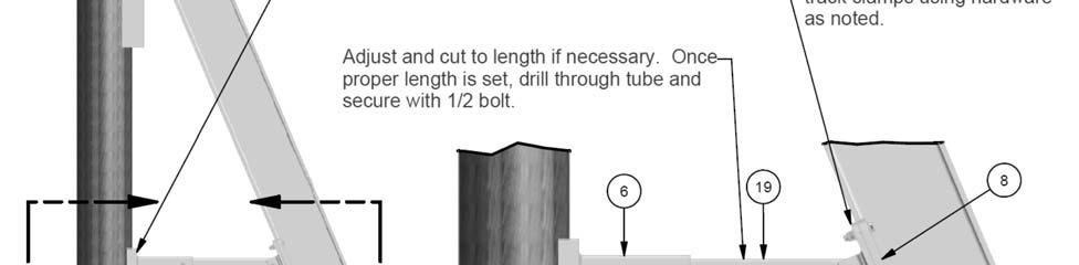
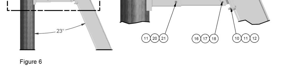
11 Page 11 Pile Mount Installation ** Please refer to figures on page 12 for installing the piling mount assemblies. ** The top of the pile mount bracket should be 6 from the top of the piling. The pile mount bracket must be level and plumb. (Figure 5A) The pile mount bracket should be attached to the pile using five ½ diameter carriage bolts or threaded rod (Contractor Supplied). The use of lag screws will void the warranty. Install bolts thru piling and secure using backing washers and nuts (Contractor Supplied). (Figure 5B) Using a level and an angle finder, set the track mount bracket to the install angle (either 10 or 23 degrees off vertical) and tighten the ¾ bolt (parts 13, 14 and 15). Track Installation ** Please refer to figures on page 12 for installing the tracks. ** (Figure 5B) Using the track mount clamps (part 8) with ½ x 2 ½ bolts and hardware (parts 10, 11 and 12), loosely bolt track to piling or seawall mount. Verify correct alignment of track and drive track to refusal (the point at which 10 impacts of a track driver does not move the track farther than ¼ ). The bracket face may be used as a guide while driving the track, but the contractor must frequently verify the alignment during the installation process. Once track is set in place, check for correct alignment one more time. Tighten all bolts on the clamps to secure the track. Repeat the above steps for the second track and mount assembly. Take special care to ensure that the second track is both plumb and parallel with the first track. To accomplish this, make sure the angle of installation is the same for both tracks and that the distance between the two tracks is equal at both the top and bottom of the tracks. (Figure 6) Install the telescopic track brace (part 6) to the piling or seawall. Measure the distance from the end of the brace to the track on a horizontal plane. If needed, cut the opposing telescopic mount inside tube (part 19) so that it will slide into the mounted end and engage at least 2 beyond the connecting hole. Once proper length is set, drill through tube and secure with ½ bolt and hardware (parts 11, 20 and 21). Secure the telescopic arm bracket to the track with track mount clamps and hardware (parts 8, 10, 11, 12, 16, 17 and 18). Remember to wrap the wire of the zincs around the mounting bolts between the washer and track clamp. The distance between the piling mount and the telescopic mount should be at least 30. The brace should be mounted as close to the high water line as possible without being mounted in the water.
12 Page 12

13 Page 13 Installing Carriage Arms and Power Head Remove the upper wheel plate from one side of the carriage. Position carriage so that lower wheel rides on the flange face of the I beam track that is closest to the slip area. Lean the carriage arm back so that the upper wheels engage and ride on the opposite face of the I beam track. Re install the upper wheel plate and tighten all hardware. To install Power Head, simply slide the mount base over the top of the track and lower until it bottoms out. Tighten the four clamp bolts to secure.

14 Page 14 Electrical: Motor Wiring for Hi Speed Lifts The motor and brake are prewired at the factory for 240V AC. The powerhead cover does not need to be removed to wire for 240V AC to a control box. All motor wire leads have been routed to a conduit box located on the back plate of the powerhead enclosure. To connect to the Bonita, Gem or Tigershark control boxes, simply connect the motor wire leads to the like color wires from the control box (ie. orange to orange). All motor wires are located inside this conduit box. **Note: Imm Quality Boat Lifts recommends that the electrical hookup be performed by a licensed electrician and conforms to all national and local electrical code. The appropriate wiring diagram and further instructions are enclosed by the OEM in the control box. Please read all instructions and wiring diagrams before connecting or changing any wires.** If you need to wire the lift for 120V AC, the motor and brake will have to be rewired. In order to access the motor and brake, remove the powerhead cover. Open the make up box attached to the motor and follow the appropriate wiring diagram and instructions that are enclosed by the OEM in the control box. Please read all instructions and wiring diagrams before connecting or changing any wires. For your convenience, the 240 Volt wiring diagrams for the Alumavator and Platinum lifts are shown below. Alumavator 240 Volt Platinum 240 Volt
15 Page 15 Installing Cable The 4,500 10,000 pound capacity lifts have two part cable systems. The 13,000 pound and higher capacity lifts have four part cable systems. To facilitate installation, the cable comes pre wound on the winder. Route the cables as shown in the figures above. 1) Remove the ¾ bolt (s) that functions as the axle (s) for the pulleys. 2) Route the cables and re install the pulleys with the bolts. 3) Make sure there are no loops, kinks or twists in the cable. 4) Attach the thimble end of the cable to the shackle. 5) Securely tighten the shackle pin.


16 Page 16 Bunk Board and Guide Post Installation WOODEN BUNKS The bunk brackets have been pre installed on the carriage I beams. The brackets may be repositioned by loosening the nuts at the bracket and sliding along the beam. Center the bunk boards on the carriage arms. Make sure the bunk boards are flush to the carriage arms and the bunk brackets. Mark, then drill (8) ½ diameter holes for mounting the bunk boards to the bunk brackets. Attach the bunk boards with the supplied stainless steel bolts and hardware. ALUMINUM BUNKS The bunk brackets may be installed vertically or at an angle of 20. Tighten bolts to clamp brackets to carriage arm. To attach aluminum bunks, first slide them over the top of the brackets. Refer to figure for location of holes. Mark, then drill holes through bunks to match existing holes in the angle brackets. Attach with ½ 13 x 4 bolts with hex nut inside and flanged nut on the outside GUIDE POST ASSEMBLY The guide post brackets come pre installed on the carriage arms. The brackets may be repositioned by loosening the nuts on the clamps and sliding along the carriage I beam. Install guide post pipe insert into the brackets and slide PVC protective sleeve over the pipe. With boat positioned on the lift, make final adjustments to the fit of the guide posts and then tighten bracket hardware.
17 Page 17 Imm Quality Boat Lifts Contact Information Phone: (239) Toll Free: Fax: (239) Website: iqboatlifts.com Sales: General Inquiries:
Installation Manual. For. Alumavator and Platinum. Vertical Installation. Elevator Boat Lifts
 Installation Manual For Alumavator and Platinum Vertical Installation Elevator Boat Lifts Page 2 Safety Precautions 1. Your boat lift is a heavy duty piece of equipment. It is important that all persons
Installation Manual. For. PWC 3000 Boat Lifts
 Installation Manual For PWC 3000 Boat Lifts Page 2 Safety Precautions 1. Your boat lift is a heavy duty piece of equipment. It is important that all persons that may operate this unit have read and understood
Installation Manual. For. Hi-Speed Alumavator / Platinum Vertical Boat Lifts
 Installation Manual For Hi-Speed Alumavator / Platinum Vertical Boat Lifts Page 2 Safety Precautions 1. Your boat lift is a heavy duty piece of equipment. It is important that all persons that may operate
Installation Manual. For. Alumavator / Platinum Boathouse Lifts
 Installation Manual For Alumavator / Platinum Boathouse Lifts Page 2 Safety Precautions 1. Your boat lift is a heavy duty piece of equipment. It is important that all persons that may operate this unit
Installation Manual. For. Trident Boat Lifts
 Installation Manual For Trident Boat Lifts Page 2 Safety Precautions 1. Your boat lift is a heavy duty piece of equipment. It is important that all persons that may operate this unit have read and understood
vertical cradle lifts installation instructions
 vertical cradle lifts installation instructions models 7,000 lb. thru 45,000 lb. important: read this manual before beginning installation of cradle lift. 5560 Ulmerton Road Clearwater, Florida 33760 1.800.878.5560
Rotating PWC Lift Installation Guide
 Rotating PWC Lift Installation Guide 800 259 8715 www.boathoistusastore.com BHUSA PWC Lift Installation Guidelines by Boat Hoist USA Check all parts on the packing list to ensure you have all the parts
PW Cantilever Lift: Part Number: Instructions and Safety Tips 1200 Ibs Capacity
 www.shoremaster.com 1200 PW Cantilever Lift: Part Number:1017507 Instructions and Safety Tips 1200 Ibs Capacity 1. 2. 3. 4. 5. CAUTION - PUT SAFETY FIRST Before attempting to install or operate this hoist,
Aluminum Boat House Lift 8K and 4K Side mount INSTALLATION MANUAL
 Aluminum Boat House Lift 8K and 4K Side mount INSTALLATION MANUAL Made in the USA! Beltless Drives! All Aluminum! No Weld Cradles! BH-USA - Longview Texas 800-259-8175 Fax (903) 758-3646 www.bh-usa.com
Boat Hoist USA. General information and guides for installing a hoist lift system onto an existing overhead structure.
 Boat Hoist USA General information and guides for installing a hoist lift system onto an existing overhead structure. Structures built on the water vary depending on the geographic location. Below represent
INSTALLATION INSTRUCTIONS
 INSTALLATION INSTRUCTIONS FIX MARINE SUPPLY (866) 998-3625 1,5OO Lb. Capacity Special Notes: Improper installation-assembly, or overloading PWC lift beyond rated capacity will void manufacturer s warranty.
A B C D E F. Tools Required (supplied by others)
") Page 1 of 17 Parts List Below Deck Automatic Retractable Security Cover Kit (1) Tube End Bearing Plate (A) (1) Rope Reel and Cover Drum Motor Assembly (B) (1) Cover Drum (1) Pulley Support Channel (2)
Page 1 of 17 Parts List Below Deck Automatic Retractable Security Cover Kit (1) Tube End Bearing Plate (A) (1) Rope Reel and Cover Drum Motor Assembly (B) (1) Cover Drum (1) Pulley Support Channel (2)
A B C D E F. b.tools Required (supplied by others) 3/16" Drill Bit 3/8" Wrench Phillips Head Screwdriver
 3/16 Drill Bit 3/8 Wrench Phillips Head Screwdriver") Page 1 of 13 5E.1 Parts List a. Below Deck Automatic Retractable Security Cover Kit (1) Tube End Bearing Plate (A) (1) Rope Reel with Motor Attached (B) (1) Rope Reel Cover (C) (1) Cover Drum (1) Cover
Page 1 of 13 5E.1 Parts List a. Below Deck Automatic Retractable Security Cover Kit (1) Tube End Bearing Plate (A) (1) Rope Reel with Motor Attached (B) (1) Rope Reel Cover (C) (1) Cover Drum (1) Cover
Midwest Industries, Inc. Ida Grove, IA Page 1
 SSV40108HAC - Hydraulic Hoist with 120 Volt Pump SSV40108HDAC - Hydraulic Hoist, Deep Water, with 120 Volt Pump SSV40108HDC - Hydraulic Hoist with 12 Volt Pump SSV40108HDDC - Hydraulic Hoist, Deep Water,
Installation Instructions Table of Contents
 Installation Instructions Table of Contents Pre- Installation of Garage Storage Lift 2 Layout the Garage Storage Lift 3 Installing the strut Channels 3 Install the Drive Assembly 5 Install the Drive Shaft
Electric Vehicle Charging Station
 EVoReel Electric Vehicle Charging Station INSTALLATION GUIDE AND USER MANUAL Model: Dual Output Pedestal Mount 30A EVoReel EVSE Model Numbers: With Basic EVSE: EV072-400-002A; With Intelligent ievse: EV072-410-002A;
ALL700/ALL700-CM INSTALLATION INSTRUCTIONS
 ALL700/ALL700-CM INSTALLATION INSTRUCTIONS Aladdin Light Lift, Inc. (256) 429-9700 61 Shields Road (877) 287-4601 Huntsville, AL 35811 www.aladdinlightlift.com Patent #5105349 WARNING: Disconnect power
Exceeding Your Expectations Through Superior Workmanship and Design
 Quality Since 1974 Exceeding Your Expectations Through Superior Workmanship and Design Model AL40120V-BB/ AL50120V-BB Lift shown with Full-Length V-Bunk. Lift shown with Hemlock Tweed SeaMark fabric canopy.
42A FLB WOOD BUNKS 43A FLB ALUMINUM BUNKS ALUMINUM CANTILEVER BOAT LIFT
 Page 1 of 9 42A --- 1265 FLB WOOD BUNKS 43A --- 1265 FLB ALUMINUM BUNKS ALUMINUM CANTILEVER BOAT LIFT Thank you for purchasing our product! Please read these instructions and follow them step by step.*
LIGHT DUTY ROLL UP DOOR
 1-800-225-6729 LIGHT DUTY ROLL UP DOOR CAUTION Use proper lifting equipment and correct lifting procedures to avoid damage or injury. MODEL 150C installation guide A rolling door is a large heavy object
MASTERsine Inverter PXA Series Installation Guide
 Backup Power System Expert TM MASTERsine Inverter PXA Series Installation Guide Important Safety Instructions IMPORTANT: Read and save this Installation Guide for future reference. This chapter contains
Harbor Light Model HL General Specifications
 Harbor Light Model HL30100 General Specifications Rev.5 02-02-17 Marina Electrical Equipment, Inc. 100 Warwick Court Williamsburg, VA 23185 Toll Free: 1-855-258-3939 Fax: 1-757-258-3988 ALL HARBOR LIGHT
Pontoon Assembly Instructions and manual. Read before using hoist.
 Page 1 Pontoon Assembly Instructions and manual. Read before using hoist. For Models 32BL18, 32BL22, 32BL25 and 42BL28 R Model 32BL22 Shown Proudly Made in Michigan By NuCraft Metal Products 402 Southline
Owner s Manual: PS SERIES WINCHES
 Owner s Manual: PS SERIES WINCHES PIERCE ARROW INC. 549 U.S. HWY 287 S. HENRIETTA, TEXAS 76365 -------------------------------------------------------- TOLL FREE 800-658-6301 FAX 940-538-4382 --------------------------------------------------------
SLIDE DOOR OPERATOR ADDENDUM
 SLIDE DOOR OPERATOR MODELS SD & GSD ADDENDUM 2 YEAR W ARRANTY Serial # (located on electrical box cover) NOT FOR RESIDENTIAL USE 1B6 Installation Date Wiring Type LISTED DOOR OPERATOR SPECIFICATIONS Adjustable
ALL W INSTALLATION INSTRUCTIONS
 ALL1000-3300W INSTALLATION INSTRUCTIONS Aladdin Light Lift, Inc. (256) 429-9700 61 Shields Road (877) 287-4601 Huntsville, AL 35811 www.aladdinlightlift.com Patent #5105349 WARNING: Disconnect power source
Recovery Winch Owner s Manual 1
 Recovery Winch Owner s Manual 1 2 Pierce Arrow 800-658-6301 Recovery Winch Owner s Manual The PS series winch is a powerful tool and must be used with extreme care. Deviating from the manual s instructions
Eaton Corp. - Marina Power and Lighting, Inc. General Specifications for Lighthouse Power Pedestal
 DRILL \ PUNCH OUT TO SIZE REQUIRED DRILL \ PUNCH OUT TO SIZE REQUIRED Lighthouse Power Pedestal - Specifications Lighthouse Power Pedestal Dimensions Height: 44.00" (1117.60 mm) Width: 13.67" (347.22 mm)
WARNING WARNING WARNING. Warnings and Cautions MOVING PARTS ENTANGLEMENT HAZARD CHEMICAL AND FIRE HAZARD FALLING OR CRUSHING HAZARD
 Warnings and Cautions As you read these instructions, you will see S, S, NOTICES and NOTES. Each message has a specific purpose. S are safety messages that indicate a potentially hazardous situation, which,
TABLE OF CONTENTS 3-7. Exploded View Assembly Cable Location and Adjustment Installation and Operation
 www.shoremaster.com DVS Vertical Lift (Double V Side): Frame ssembly Instructions. Models: 0DVS ft Wide, 00lb Capacity Part #: 07 009DVS 9ft Wide, 000lb Capacity Part #: 0070 00DVS 0ft Wide, 000lb Capacity
Owner s Manual: PS4000 4,000 LB. WINCH
 Owner s Manual: PS4000 4,000 LB. WINCH PIERCE ARROW INC. 549 U.S. HWY 287 S. HENRIETTA, TEXAS 76365 ---------------------------------------------------- TOLL FREE 800-658-6301 FAX 940-538-4382 ----------------------------------------------------
CAUTION - PUT SAFETY FIRST
 www.shoremaster.com DVS Vertical Lift (Double V Side): Frame ssembly Instructions. Models: 00DVS 0ft Wide Pontoon, 000 Capacity Part #: 0 0(with Pontoon Guide/Cradles) 00DVS 0ft Wide, 000lb Capacity Part
OPERATING & INSTRUCTION MANUAL
 251 Welsh Pool Rd Exton, PA 19341 610-941- 4333 www.safetyhoistcompany.com OPERATING & INSTRUCTION MANUAL VH-300 BRIGGS & STRATTON VH-300 HONDA IMPORTANT RETAIN THIS MANUAL For instruction on assembly
KWSL2000RM ! CAUTION!! READ AND UNDERSTAND THIS MANUAL BEFORE INSTALLATION AND OPERATION OF THIS PRODUCT. DO NOT RETURN THIS PRODUCT TO SELLER.
 Assembly & Operating Instructions KWSL2000RM 2000 Lb. 12VDC Electric Winch! CAUTION!! READ AND UNDERSTAND THIS MANUAL BEFORE INSTALLATION AND OPERATION OF THIS PRODUCT. DO NOT RETURN THIS PRODUCT TO SELLER.
WARNING: HARDWARE PACK (A ) DO NOT INSTALL if the truck has been lifted and the stock jounce bumper spacers are not on the vehicle.
 DO NOT INSTALL if the truck has been lifted and the stock jounce bumper spacers are not on the vehicle.") DO NOT INSTALL if the truck has been lifted and the stock jounce bumper spacers are not on the vehicle. 2550 WARNING: Do not inflate this assembly when it is unrestricted. The assembly must be restricted
DO NOT INSTALL if the truck has been lifted and the stock jounce bumper spacers are not on the vehicle. 2550 WARNING: Do not inflate this assembly when it is unrestricted. The assembly must be restricted
READ THIS FIRST. Read and Save These Instructions AIR CURTAINS INSTALLATION INSTRUCTIONS S-XHD SERIES. TMI, LLC Managing Environments
 READ THIS FIRST Carefully examine the crate(s) for damage before opening. If the carton is damaged, immediately notify shipping company. If the unit(s) were shipped on wooden skids, remove protective wood
HP BladeSystem c7000 Carrier-Grade Options Installation Guide
 HP BladeSystem c7000 Carrier-Grade Options Installation Guide Part Number 5991-8062 September 2009 (Second Edition) Copyright 2009 Hewlett-Packard Development Company, L.P. The information contained herein
Start-up and Operation
 Start-up and Operation NEVER FORGET THAT ANY MACHINE CAN BE VERY DANGEROUS WHEN NOT OPERATED CORRECTLY AND SAFELY. ALWAYS VISUALLY CHECK TO MAKE SURE THAT ALL PERSONS ARE CLEAR BEFORE TURNING ON ANY CONTROLS.
EASY CONNECT CRANE KIT Festoon Conductor Systems
 ASSEMBLY INSTRUCTION MANUAL EASY CONNECT CRANE KIT Festoon Conductor Systems October, 2005 Copyright 2005, Yale Lift-Tech, division of Columbus McKinnon Corporation Part No. 117463-05 Mounting Instructions
INSTALLATION MANUAL. UltraLift UL2. MODELS UL2 through UL W. Blue Starr Dr. Claremore, OK (918) Pub.
 Pub.") INSTALLATION MANUAL UltraLift UL2 MODELS 10000 UL2 through 32000 UL2 915 W. Blue Starr Dr. Claremore, OK 74017 (918)341-6811 Pub. :4/27/17 HydroHoist Marine Group HydroHoist Marine Group Product Installation
INSTALLATION MANUAL UltraLift UL2 MODELS 10000 UL2 through 32000 UL2 915 W. Blue Starr Dr. Claremore, OK 74017 (918)341-6811 Pub. :4/27/17 HydroHoist Marine Group HydroHoist Marine Group Product Installation
2000 lb WINCH. Instruction and Operation Manual
 2000 lb WINCH Instruction and Operation Manual 12 Volt DC Electric Winch PART NUMBER 823-223C OPERATING INSTRUCTIONS READ BEFORE OPERATING CUSTOMER MUST RECEIVE COPY OF OPERATING INSTRUCTIONS AT TIME OF
INSTALLATION INSTRUCTIONS
 INSTALLATION INSTRUCTIONS "Elevate your storage needs to a Higher Level" MODEL # ASL-500 Aladdin Storage Lift, LLC. Aladdin 61 Shields StorageRoad Lift, LLC. Huntsville, AL 35811 Phone (256) 429-9700 Fax
INSTALLATION MANUAL SHALLOW WATER. Models. 915 W. Blue Starr Dr. Claremore, OK (918) Pub. 11/29/17
 Pub. 11/29/17") INSTALLATION MANUAL SHALLOW WATER Models 6000 7500 8800 9000 915 W. Blue Starr Dr. Claremore, OK 74017 (918)341-6811 Pub. 11/29/17 Publication 11/29/17 HydroHoist Marine Group HydroHoist Marine Group Product
INSTALLATION MANUAL SHALLOW WATER Models 6000 7500 8800 9000 915 W. Blue Starr Dr. Claremore, OK 74017 (918)341-6811 Pub. 11/29/17 Publication 11/29/17 HydroHoist Marine Group HydroHoist Marine Group Product
ES-6500V ES-6500P ES-6500W 915 W.
 INSTALLATION MANUAL E-Series MODELS ES-6500V ES-6500P ES-6500W R HydroHoist Marine Group, Inc. 915 W. Blue Starr Dr. Claremore, OK 74017 1-800-825-3379 Pub. May, 2014 Publication May 2014 HydroHoist Marine
Top-of-Pole Mount for 4 Modules (TPM4) For Module Types D, E, F, & G
 For Module Types D, E, F, & G") Module Type Width Length D 31-33 60-67 E 38-40 51-53 F 38-42 58-61 G 37-42 61-67 Top-of-Pole Mount for 4 Modules (TPM4) For Module Types D, E, F, & G ASSEMBLY INSTRUCTIONS step-by-step assembly and installation
Module Type Width Length D 31-33 60-67 E 38-40 51-53 F 38-42 58-61 G 37-42 61-67 Top-of-Pole Mount for 4 Modules (TPM4) For Module Types D, E, F, & G ASSEMBLY INSTRUCTIONS step-by-step assembly and installation
Lbs Kgs Ft M
 Installation Instructions for 92600 ATV Winch 3000 lb. Rated Pull SPECIFICATIONS Rated line pull: 3000 lbs. (1360kgs) single line Motor: Permanent magnetic DC 12V with 1.2 hp. /0.9kw output Gear: Differential
Installationn Instruction Manual
 Table of Contents Supplied Kit Parts.Page 2 Required Tool List Page 2 Step by Step Installation Instructions Pages 3-6 Battery Requirements.Page 6 Operation Page 7 Maintenance Page 7 Wiring Diagrams..Page
Chain/Belt Drive Models PRE-INSTALLATION CONSIDERATIONS
 38968503545. 08/2017 ASSEMBLY/INSTALLATION Chain/Belt Drive Models PRE-INSTALLATION CONSIDERATIONS This opener includes parts and supplies needed for installation in most garages and on most garage doors.
INSTALLATION MANUAL. UL2 Front Mount MODELS 4400 FM 6600 FM
 INSTALLATION MANUAL UL2 Front Mount MODELS 4400 FM 6600 FM R HydroHoist Boat Lifts HydroHoist Marine Group P.O. Box 1286 Claremore, OK USA 74018 1-800-825-3379 www.boatlift.com Pub. 10/14/08 HydroHoist
HOISTS RATCHET LEVER HOISTS
 Yale HOISTS RATCHET LEVER HOISTS Yale PE & RS Ratchet Lever Hoist / to ton capacities Link chain models Light and portable Weatherized load brake Requires less handle pull to lift full load Efficient Yale
Important. Contents. Contact us:
 Operator's Manual Third Edition Third Printing Important Read, understand and obey these safety rules and operating instructions before operating this machine. Only trained and authorized personnel shall
4' x 10' Assembly Instructions. We re Here To Help! Call Toll Free Section Roll In Dock Shown
 4' x 10' Assembly Instructions TM 4 Section Roll In Dock Shown We re Here To Help! Call Toll Free 1-888-752-9782 Customer Service: Monday - Friday, 8:00 A.M. to 5:00 P.M. C.S.T. TABLE OF CONTENTS - ALUMINUM
INSTALLATION AND OPERATING INSTRUCTIONS
 INSTALLATION AND OPERATING INSTRUCTIONS MANUAL TRANSFER SWITCHES FROM 0 Residential Wattage Requirements Appliance Running Watts Add watts for starting Furnace blower, gas or fuel 1/8 hp 300 500 1/8 hp
PRODUCT MANUAL TILE CUTTING MACHINE. . Operation. Parts List and Diagram SPECIFICATIONS CAUTION:
 FLORCRAFTT TM PRODUCT MANUAL SKU NUMBER 709-4242 SERIAL NUMBER: CAUTION: FOR YOUR OWN SAFETY READ INSTRUCTION MANUAL COMPLETELY AND CAREFULLY BEFORE OPERATING THIS 7 TILECUTTING MACHINE SPECIFICATIONS
PORTA-DOCK, INC. 100A 1284 ALUMINUM CANTILEVER BOAT LIFT
 Page 1 of 7 PORTA-DOCK, INC. 100A 1284 ALUMINUM CANTILEVER BOAT LIFT Thank you for purchasing our product! Please read these instructions and follow them step by step. * STEP 1. Separate and group like
Important. Contents. Contact us:
 Operator's Manual First Edition Ninth Printing Important Read, understand and obey these safety rules and operating instructions before operating this machine. Only trained and authorized personnel shall
JEEVES. JEEVES Installation Manual. Installation Manual The Easiest Do-It-Yourself Dumbwaiter on the Market
 1 888-323-8755 www.nwlifts.com JEEVES Installation Manual The Easiest Do-It-Yourself Dumbwaiter on the Market This manual will cover the installation procedure step-by-step. The installation of this dumbwaiter
ALL200RM/ALL200RM-CM
 ALL200RM/ALL200RM-CM INSTALLATION INSTRUCTIONS Aladdin Light Lift, Inc. (256) 429-9700 61 Shields Road (877) 287-4601 Huntsville, AL 35811 www.aladdinlightlift.com Patent #5105349 WARNING: Disconnect power
ALL700RM-230V INSTALLATION INSTRUCTIONS
 ALL700RM-230V INSTALLATION INSTRUCTIONS Aladdin Light Lift, Inc. (256) 429-9700 61 Shields Road (877) 287-4601 Huntsville, AL 35811 www.aladdinlightlift.com Patent #5105349 WARNING: Disconnect power source
Page 1. Sculling Boat Hoists Assembly and User s Manual
 Page 1 Sculling Boat Hoists Assembly and User s Manual Items in the box: (2) Hoist cradles (1) Hoist crossbar (1) Hoist winch assembly (3) 1/4 X 4 Lag screws with 1/4 washers (2) Single pulley with eye
INSTALLATION INSTRUCTIONS
 INSTALLATION INSTRUCTIONS ----1075 North Ave. Sanger, CA 93657-3539 toll free: 800-445-3767 web: www.belltechcorp.com---- 5052 AIR JACK 94-99 DODGE ½ TON RAM C-1500 Congratulations! You were selective
PART B BRAND SPECIFIC MANUAL
 SPA OWNER S MANUAL IMPORTANT SAFETY INSTRUCTIONS PART B BRAND SPECIFIC MANUAL ELECTRICAL CONNECTION KEYPAD OPERATION 200 Series 200-M-B-16 Read in conjunction with Part A General Manual to form a complete
Marlon Xplore SxS Deck Owner s Manual Assembly & Installation Instructions
 Marlon Xplore SxS Deck Owner s Manual Assembly & Installation Instructions 2850lbs load max on deck 2500lbs load max on ramps Marlon Recreational Products www.marlonproducts.com 1-800-663-7367 IMPORTANT
! DANGER Lb. Winch Mounting Instructions. Tools required: Before You Start. Assembly Instructions. General Information. Manual No.
 500 Lb. Winch Mounting Instructions For 400/4400 NT/ST, 40/440 ST And 40/440 ST Manual No. 70-86M Before You Start! When you see this symbol, the subsequent instructions and warnings are serious - follow
Installing Your 220v J-POD Kit
 Installing Your 220v J-POD Kit NOTE: There are two J-POD versions depending on your pump voltage - 110 volt and 220 volt. MAKE SURE YOU HAVE THE RIGHT VOLTAGE J-POD FOR YOUR. Using software and hardware
750 Series Press Conveyor Installation and Maintenance Manual
 750 Series Press Conveyor Installation and Maintenance Manual Metzgar Conveyor Co. - 2010 METZGAR CONVEYORS SAFETY PRECAUTIONS WARNING: DO NOT ATTEMPT MAINTENANCE ON ANY CONVEYORS WHILE IN OPERATION. BEFORE
Outload Trough Roller Conveyor
 Outload Trough Roller Conveyor OWNER'S MANUAL 00003400 (8/99) Table of Contents Warranty Information.............................. Inside Front Cover Operator Qualifications / Sign Off Sheet..............................
Sectional and Tilting Door Opener Installation Instructions and User Guide
 Sectional and Tilting Door Opener Installation Instructions and User Guide ET-600E ET-800E ET-1000E S/N WARNING Please read the manual carefully before installation and use. The installation of your new
LIFT MATE BOAT LIFT MOTOR ASSEMBLY. Assembly and Operating Manual.
 LIFT MATE BOAT LIFT MOTOR ASSEMBLY Assembly and Operating Manual www.boatliftmotor.com 03/26/2010 LIMITED WARRANTY Shoreline Industries, Inc. warrants its products shall be free from defects in materials
Installation Instructions
 Installation Instructions MX3635-01 Rev. E Models HydraSwing 40s HydraSwing 40F 4,000 lb (1,814 kg) 10-15 seconds HydraSwing 40 4,000 lb (1,814 kg) 15-20 seconds HydraSwing 40 Twin 4,000 lb (1,814 kg)/leaf
INSTALLATION MANUAL SHALLOW WATER. HydroHoist Boat Lifts HydroHoist Marine Group P.O. Box 1286 Claremore, OK USA
 INSTALLATION MANUAL SHALLOW WATER MODEL 5000 R HydroHoist Boat Lifts HydroHoist Marine Group P.O. Box 1286 Claremore, OK USA 74018 1-800-825-3379 www.boatlift.com Pub. 01/12/09 Publication 01/12/09 HydroHoist
20 Gauge Super-Speed. shoprpmachine
 Operator tor s s manual 20 Gauge Super-Speed 1 WARRANTY Our guarantee on the products we manufacture is limited to repair or replacement without charge, of any part found to be defective in materials or
DayStar Quick Start Guide
 DayStar Quick Start Guide Thank you for buying a Stewart Sign! Care has been taken to provide a quality product that will serve you well for many years. If for any reason you are not entirely satisfied
INSTALLATION MANUAL. Level Lift L MODELS 30002T L 40002T L 60002T L 60003T L 80002T L 80004T L
 INSTALLATION MANUAL Level Lift L MODELS 30002T L 40002T L 60002T L 60003T L 80002T L 80004T L HydroHoist Boat Lifts HydroHoist International, Inc. P.O. Box 1286 Claremore, OK USA 74018 1-800-825-3379 Pub.
DC Series Installation Manual (# )
") DC Series Installation Manual (# 101630) Page 1 of 33 In this booklet you will find: TOWER INSTALLATION... 3 U-Bolt Style mount... 4 Side Frame Style mount... 4 PIVOT INSTALLATION... 5 External Pivot Installation:
DC Series Installation Manual (# 101630) Page 1 of 33 In this booklet you will find: TOWER INSTALLATION... 3 U-Bolt Style mount... 4 Side Frame Style mount... 4 PIVOT INSTALLATION... 5 External Pivot Installation:
450 Series Belt Driven Live Roller Curve Conveyor Installation and Maintenance Manual
 450 Series Belt Driven Live Roller Curve Conveyor Installation and Maintenance Manual Metzgar Conveyor Co. - 2010 METZGAR CONVEYORS SAFETY PRECAUTIONS WARNING: DO NOT ATTEMPT MAINTENANCE ON ANY CONVEYORS
Instructions for MB832 Manual Barrier Ver0614
 Instructions for MB832 Manual Barrier Ver0614 Read all the instructions before starting It is recommended that Locktite Blue brand thread sealant be used for all arm and pivot bolts as added protection
Wallace Tri-Adjustable Gantry Cranes Square Tube Assembly Instructions
 Wallace Tri-Adjustable Gantry Cranes Square Tube Assembly Instructions For any additional information, Please call 1- S 1. Read and understand instructions before using this gantry. 2. Inspect gantry thoroughly
VPL-SH1 Vertical Platform Lift
 VPL-SH1 Vertical Platform Lift SH1-28 SH1-52 SH1-72 SH1-105 www.serenityhcp.com Page 1 of 27 Standard_Vertical_Lift_Rev 7 Table of Contents Site Preparation and Electrical Guidelines..... 3 Specifications...
General Specifications for Lighthouse Power Pedestal
 Dimensions Height: 44.00 11 (1117.60 mm) Width: 13.67" (347.22 mm) Depth: 13.75" (349.25 mm) Lighthou98 Base Diagram ---13,75 1 --- Approximate Weight: 30 lbs. (13.6 kg) Multiply base dimensions by 25.4
7. Residential Single-Family and Duplex Buildings (Dwellings)
") Sin g le -F a mily a n d Du p le x Bu ild in g s 2016 Electric Service Requirements, 2 nd Edition Section 7 Section 7 Residential Single-Family and Duplex Buildings (Dwellings) Directory Page 7.1 General
Sin g le -F a mily a n d Du p le x Bu ild in g s 2016 Electric Service Requirements, 2 nd Edition Section 7 Section 7 Residential Single-Family and Duplex Buildings (Dwellings) Directory Page 7.1 General
RIG-I-FLEX 140 SERIES CURTAIN TRACKS
 RIG-I-FLEX 140 SERIES CURTAIN TRACKS Parts Included 140 RIG-I-FLEX CWANA code CORD OPERATED/MOTORIZED WALK-ALONG 140 (240) 140-R (240-R) 141 (241) 141-R (241-R) 142 (242) 142-R (242-R) STRAIGHT CURVED
Service Requirements
 Service Requirements General Contact Idaho Power before beginning work on any new service. All meter installations must meet current electrical code requirements and display the proper electrical permit.
dv Sentry TM 208V 600V INSTALLATION GUIDE Quick Reference ❶ How to Install Pages 6 14 ❷ Startup/Troubleshooting Pages WARNING
 dv Sentry TM 208V 600V INSTALLATION GUIDE FORM: DVS-IG-E REL. January 2018 REV. 003 2018 MTE Corporation High Voltage! Only a qualified electrician can carry out the electrical installation of this filter.
ASSEMBLY INSTRUCTIONS / OWNERS MANUAL AIR BIKE AB-1
 AIR BIKE AB- ASSEMBLY INSTRUCTIONS / OWNERS MANUAL IMPORTANT : READ ALL ASSEMBLY INSTRUCTIONS AND SAFETY PRECAUTIONS BEFORE USING THIS PRODUCT. REFERENCE ALL SAFETY GUIDELINES AND WARNING LABELS. RETAIN
VHM-P (Non-Locking) and VHM-PL (Locking) Variable Height Arm with Slide-In Mounting Plate
 and VHM-PL (Locking) Variable Height Arm with Slide-In Mounting Plate") 3875 Cypress Drive Petaluma, CA 94954 800.228.2555 +1.707.773.1100 Fax 707.773.1180 www.gcx.com VHM-P (Non-Locking) and VHM-PL (Locking) Variable Height Arm with Slide-In Mounting Plate (Refer to qualified
3875 Cypress Drive Petaluma, CA 94954 800.228.2555 +1.707.773.1100 Fax 707.773.1180 www.gcx.com VHM-P (Non-Locking) and VHM-PL (Locking) Variable Height Arm with Slide-In Mounting Plate (Refer to qualified
INSTALLATION GUIDE AND USER MANUAL
 Electric Vehicle Charging Station INSTALLATION GUIDE AND USER MANUAL SAE J1772 AC Level 2 EVSE Model: 30A EVoCharge EVSE Wall Mount P/N: EV072-300-001A Version 2.0 IMPORTANT Read this manual thoroughly
INSTALLATION INSTRUCTIONS
 270 INSTALLATION INSTRUCTIONS 5-6 ! IMPORTANT PLEASE DON T HURT YOURSELF, YOUR KIT OR YOUR VEHICLE. TAKE A MINUTE TO READ THIS IMPORTANT INFORMATION. This kit is to be used on a pickup truck only, and
PSJ-2212, PSJ-3612, PSJ-4424
 Model: PSJ-2212, PSJ-3612, PSJ-4424 Jump Starter and DC Power Source OWNER S MANUAL PSJ-2212 PLEASE SAVE THIS OWNER S MANUAL AND READ BEFORE EACH USE. This manual will explain how to use your jump starter
Visit Our Our Our Web Site at:
 Visit Our Our Our Web Site at: ww w ww w w w w. l o c k f o rr r m e r r r. c o m 711 OGDEN AVENUE, LISLE, ILLINOIS 60532-1399 Phone (630) 964-8000 Fax (630) 964-5685 09-1998 Operator tor s manual 20 Gauge
IMM Quality Boat Lifts. The Smart Choice. Product Catalog.
 Product Catalog www.iqboatlifts.com Table of Contents Why Choose Imm Quality?... 4 Custom Design Experts... 6 Imm Quality Drive Systems... 7 Imm Quality Vertical Lifts... 8 Superlift... 10 Titan Yacht
Guide to Installing Y o u r H a r m a r S t a i r L i f t
 Guide to Installing Y o u r H a r m a r S t a i r L i f t 2 W E L C O M E T O T H E H A R M A R F A M I L Y Congratulations on your purchase of a Harmar Access Stairway Lift. These instructions will assist
WARNING WARNING CAUTION. Warnings and Cautions MOVING PARTS ENTANGLEMENT HAZARD MOVING PARTS ENTANGLEMENT HAZARD CHEMICAL AND FIRE HAZARD
 Warnings and Cautions As you read these instructions, you will see S, S, NOTICES and NOTES. Each message has a specific purpose. S are safety messages that indicate a potentially hazardous situation, which,
HL4K PONTOON LIFT INSTRUCTIONS
 HL4K PONTOON LIFT INSTRUCTIONS REIMANN & GEORGER CORPORATION MARINE PRODUCTS P/N 6114179 5/02/14 BUFFALO, NY TABLE OF CONTENTS CHAPTER TITLE PAGE 1 SAFETY... 1 1.1 Introduction... 1 1.2 Safety Definitions...
3875 Cypress Drive Petaluma, CA Fax
 3875 Cypress Drive Petaluma, CA 94954 800.228.2555 +1.707.773.1100 Fax 707.773.1180 www.gcx.com VHM-P (Non-Locking) Variable Height Arm with Fixed Angle Front End for Flat Panel / Keyboard Bracket (L Brackets
Package Contents Part A (3) I-Beam (1) Base (2) Other parts
 I-Beam (1) Base (2) Other parts") Page 1 Installation Instructions for 81245 Adjustable Height Gantry Crane 1-Ton Capacity Table of Contents Important Safety Information pg. 2 Specific Operation Warnings pg. 2 Main Parts of Product pg.
Page 1 Installation Instructions for 81245 Adjustable Height Gantry Crane 1-Ton Capacity Table of Contents Important Safety Information pg. 2 Specific Operation Warnings pg. 2 Main Parts of Product pg.
PIRANHA I & 2 INSTALL GUIDE
 TOP Use 5/32" drill bit DO NOT LET DEADRISE INTERSECT THIS LINE PLACE EITHER CORNER ON DEADRISE ANGLE PIRANHA I & 2 INSTALL GUIDE Two components need to be installed on the boat: the transducer and the
Patriot Portable Material Hoist 850/1000/2000. Operator s Manual
 Patriot Portable Material Hoist 850/1000/2000 Operator s Manual Manual must be read carefully by all operators before hoist is set-up and used. Failure to follow all directions and warnings for safe mounting
GAS CYLINDER LIFTS BEFORE YOU BEGIN
 I N S T R U C T I O N M A N U A L GAS CYLINDER LIFTS The LM Series gas cylinder lifts are smooth, quiet reliable lift mechanisms for your valuable equipment in a mobile application. The LM Series can be
Belt Conveyor Systems
 Belt Conveyor Systems Product & Installation Manual 24-in, 36-in, and 48-in Widths Manual #: IM-704-01 i 11/14 ii Table of Contents SECTION 1 OVERVIEW 1-1 System Length 1-1 Component Dimensions 1-2 Drive