Wheeled Robotic Mobility. Dimi Apostolopoulos
|
|
|
- Morgan Bryant
- 5 years ago
- Views:
Transcription

1 Wheeled Robotic Mobility Dimi Apostolopoulos
2 Significance of Mobility Move Position Transport Employ instruments and tools React to work loads in a controllable fashion ROBOTIC MOBILITY Dimi Apostolopoulos Page 2


3 Classification by Locomotion Type Wheels Legs Tracks Hybrids Special limbs Special joints ESA ExoMars Rover JAXA Rover NASA JSC Chariot NASA JPL ATHLETE ROBOTIC MOBILITY Dimi Apostolopoulos Page 3


4 Selecting Locomotion Type Wheels for Faster movement Generally fewer actuated DOFs Better packaging & survivability Hybrids for multi-mission tasks Legged for very rough terrain Reconfigurable, hopping systems for extreme terrain Undulatory for confined spaces Scaling considerations are critical ROBOTIC MOBILITY Dimi Apostolopoulos Page 4


5 This Lecture Wheeled Mobility 400 kg 200 kg 20 kg 600 kg CMU Systems 1200 kg 6000 kg ROBOTIC MOBILITY Dimi Apostolopoulos Page 5


6 Elements of Robotic Mobility ROBOTIC MOBILITY Dimi Apostolopoulos Page 6
7 Elements of Robotic Mobility Critical Dimensions Suspension 3-D Geometry Wheel (number, geometry, disposition) Actuation Inherent features for controllability C.G. & Ground Clearance Drive (type, actuation Requirements) Optimized FOV Steering (scheme, geometry, kinematics) Sensor Placement ROBOTIC MOBILITY Dimi Apostolopoulos Page 7
8 Robotic Mobility Locomotion elements (geometry, elastic vs. rigid) Wheel disposition and chassis geometry Drive scheme (independent vs. coordinated) Steering scheme (explicit vs. induced) Suspension (from passive to active, 2D vs. 3D) Articulation (passive vs. active, # & type of axis) Control (speed, traction, slip) Actuation (electric/hydraulic, etc.) Sensing (direct vs. inferred) Inherent features for higher terrainability and ease of control ROBOTIC MOBILITY Dimi Apostolopoulos Page 8


9 Synthesizing Novel Robotic Mobility Requirements Analysis Conceptual Design Preliminary Design Configuration Design Critical Design Development ROBOTIC MOBILITY Dimi Apostolopoulos Page 9
10 Physics-based Analysis of Mobility Requirements Analysis Quasi-static mechanics of robot-terrain interaction (force, torque, power, energy) Kinematics & dynamics Conceptual Design Stability analysis Controllability analysis Preliminary Design Physics of sensing Configuration Design Critical Design Development ROBOTIC MOBILITY Dimi Apostolopoulos Page 10
11 In-soil Performance Terramechanics Wheel-soil interaction models Wheel sinkage Motion resistance and traction Force, torque, power, energy Sizing wheels, drive actuation, drive electronics, drive mechanisms ROBOTIC MOBILITY Dimi Apostolopoulos Page 11

12 Wheel-ground Contact Contact patch A AbL (, ) W A This stress is called ground pressure. Tracks -- rectangular patch. But ground pressure is not always uniform. Sometimes get more sinkage than expected. p p ROBOTIC MOBILITY Dimi Apostolopoulos Page 12

13 Basic Physics of Wheel-Soil Interaction F A Normal Stress (pressure) p F A F F A Relates to ground pressure and sinkage. Shear Stress F A F Relates to traction, slip, and skid. ROBOTIC MOBILITY Dimi Apostolopoulos Page 13


14 Traction and Force W F 1 F 2 R 1 R 2 F R What are drive forces to overcome soil resistances? Will soil support the loads? F: Traction, R: Resistance, F > soil s capacity to react to loads ROBOTIC MOBILITY Dimi Apostolopoulos Page 14
15 Motion Resistance R c W Tandem W 2 W 1 σ F --Resistance by compacting soil (sinkage) under the wheel k b c Rc b k n1 z0 n1 The wider the wheel and greater the sinkage, the greater the resistance. R c2 F 2 R c1 ROBOTIC MOBILITY Dimi Apostolopoulos Page 15 F 1 Equal to work/length of pressing a block of width b to depth z.

16 Wheel Slip, Soil Thrust & Traction Not all rotational velocity is translated into linear velocity. ω v Rate of slip: i o r v v H Cannot be easily predicted, but can be measured and used for feedback control. Soil thrust actually takes slip into account: F K H AcW tan 1 1e io Ideal Soil Thrust i o K Slip Term ROBOTIC MOBILITY Dimi Apostolopoulos Page 16
17 Physics-Based Modeling & Analysis CMU s LocSyn Tool Example: Required Drive Torque T drws R c + R b + R r + R g d w = Compaction Resistance Drive Torque vs. Drive Torque Wheel Loading vs. Slope 2 b w sin + R b sin cos 2cKc z K z 2 l r 90 2 cl r 2 = cl w w tan r K c N c tan K 2N z w 2 = cos = cos = acos tan l d r = z w tan 45 - w 2 R cr w = 2 n W w cos 2n d w 2n n + 1 2n n n + 1 k c + b w k n + 1 d w k c + b w k = 3W w cos 2n n + 1 2n + 2 2n + 1 R crw 3 n n + 1 Drive Torque vs. Rolling Radius Drive Torque vs. Tire Width Number of wheels: 6 Wheelbase: 2.5 m x 1.5 m Roll Radius: 0.25 m Tire width: 0.20 m Parametric analysis: Select wheel & mobility chassis key dimensions, and size actuators ROBOTIC MOBILITY Dimi Apostolopoulos Page 17
18 Significance of All-Wheel Drive R c2 W 2 F2 Rc1 W 1 F 1 Positive traction Greater pull Better slope climbing Better obstacle climbing Smoother control W 2 W 1 W F2 F 1 Drawbar Pull R c2 Rc1 θ θ N ROBOTIC MOBILITY Dimi Apostolopoulos Page 18


19 All-Wheel Drive for Obstacle Climbing Wheel dimension Chassis dimension ROBOTIC MOBILITY Dimi Apostolopoulos Page 19


20 Wheel Size vs. Number of Wheels Estimated ~2.2 W per wheel 150 kg 3-wheeled rover / ~50 kg/wheel 0.75 m rolling radius SILVRCLAW Martian soil: c= 1 kpa, = 18 deg ROBOTIC MOBILITY Dimi Apostolopoulos Page 20
 is approximately equal to max gradeability as")

21 Drawbar Pull (DP) Difference between soil thrust (max traction) and rolling resistance. c Max DP: 550 N Max slope: 22 deg Key metric of mobility; how much the vehicle can pull arctan(dp/w) is approximately equal to max gradeability as imposed by wheel-terrain interaction a b d e Analytical estimates within 3% of actual measured DP Direction of travel a. Robot driving normally b. Cable tension rapidly increases c. Wheels slipping d. Motion controller fault, at least one wheel stops servoing e. Robot reverses, cable goes slack Load cell Steel cable Wall ROBOTIC MOBILITY Dimi Apostolopoulos Page 21


22 Inclined Terrain Mobility Downhill gradeability Cross-hill gradeability Static stability vs. soil stability vs. actuator limitations ROBOTIC MOBILITY Dimi Apostolopoulos Page 22


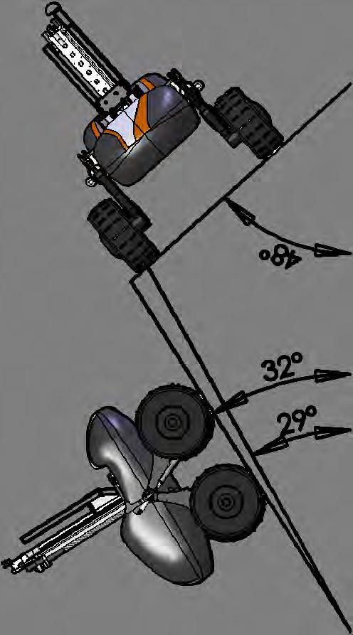
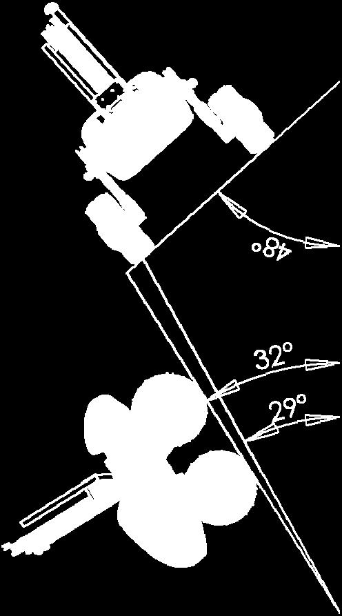

23 Static Stability Limits *nomin al *low *high (values from tilt-table testing) ROBOTIC MOBILITY Dimi Apostolopoulos Page 23


 ROBOTIC")
24 Gradeability Static vs. Terrain Stability Tip-over Rollover The robot static stability limits to be greater than the terrain stability limits Analysis to help optimize vehicle geometry (center of gravity C.G. location, wheel base, wheel size) ROBOTIC MOBILITY Dimi Apostolopoulos Page 24

 d 2 x/dt Robot Braking")

25 Gradeability Dynamic Limitations Analysis to help optimize vehicle geometry (C.G. location) and dynamic characteristics (deceleration performance) d 2 x/dt Robot Braking This analysis can be used to set max deceleration limits that the motion control imposes ROBOTIC MOBILITY Dimi Apostolopoulos Page 25

26 Improving Gradeability through Active Posturing Leaning posture at 20 ROBOTIC MOBILITY Dimi Apostolopoulos Page 26

27 Improving Path Tracking with Active Posturing Level posture Leaning posture ROBOTIC MOBILITY Dimi Apostolopoulos Page 27

28 Maneuverability Optimal steering geometry Turning radius Force, torque, power, energy Sizing wheels, drive/steering actuation, drive/steering electronics, steering mechanisms ROBOTIC MOBILITY Dimi Apostolopoulos Page 28


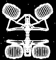
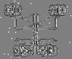
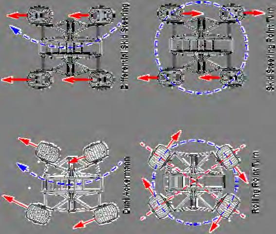
29 Steering Geometries Knuckle steering Single-axis (Ackermann) Four-wheel steering (double Ackermann, independent) Crab steering Articulated frame steering Skid steering Combined steering ROBOTIC MOBILITY Dimi Apostolopoulos Page 29
 and shorten the wheel base (decrease L) F F o i M R B M R R B x R M pbxdx Q x ROBOTIC MOBILITY Dimi Apostolopoulos")
30 Steering Quasi-static Mechanics Overcome a moment resistance (M R ) in addition to compaction and bulldozing resistance. Moment resistance caused by lateral Coulomb friction. R i i 0 To minimize moment resistance, widen the body (increase B) and shorten the wheel base (decrease L) F F o i M R B M R R B x R M pbxdx Q x ROBOTIC MOBILITY Dimi Apostolopoulos Page 30
31 Skid Steering Power Draw L/2 L/2 F y4 All Intermittent Torques F y3 F Y1 F Y3 L L/2 F y1 M r Pivot Turn About Center Axle o F y2 Operational Condition Pivot turn about center axle Hard Surface No Obstruction = 0.7, R r = 1.5% RR = 1.5% Pivot turn about center axle Soft Surface No Obstruction = 0.4, R r = 25% f RR = 25% Power 3 x drive 3 x drive F Y2 F Y4 Pivot turn around obstacle Hard Surface Frt Wheel Obstructed = 0.7 f RR = 1.5% 3.5 x drive o Pivot Turn Around Obstacle ROBOTIC MOBILITY Dimi Apostolopoulos Page 31
 Explicit (ES) ROBOTIC MOBILITY Dimi Apostolopoulos Page")
32 Evaluation of Steering Geometries Ackerman (AS) Articulated (RS) Explicit (ES) ROBOTIC MOBILITY Dimi Apostolopoulos Page 32
 Explicit (ES) ROBOTIC MOBILITY Dimi Apostolopoulos")
33 Significance of Explicit Wheel Steering Ackerman (AS) Better terrainability Finer maneuverability More control flexibility Better tracking Articulated (RS) Explicit (ES) ROBOTIC MOBILITY Dimi Apostolopoulos Page 33
 and control parameters (max allowable steering speed) mv 2 /r ROBOTIC")
34 Steering Limitations Analysis to help optimize vehicle geometry (C.G. location, track width) and control parameters (max allowable steering speed) mv 2 /r ROBOTIC MOBILITY Dimi Apostolopoulos Page 34
35 Terrain Adaptation & Motion Smoothing Optimal suspension geometry Passive Dynamic (spring/damper type) Geometric Passive with active adjustability Active Elastic mobility elements ROBOTIC MOBILITY Dimi Apostolopoulos Page 35


36 Geometric Suspensions Averaging Pivoted Arm Body leveled Rocker arms at opposite angles ROBOTIC MOBILITY Dimi Apostolopoulos Page 36


37 Passive Geometric Suspensions - 6x6 Chasses JPL MER JPL Pathfinder JPL Rocky Series ESA ExoMars Rover EPFL SOLERO EPFLCRAB ROBOTIC MOBILITY Dimi Apostolopoulos Page 37


38 Passive Geometric Suspension 4x4 Chasses CMU Hyperion NASA Ames K10 Pitch CMU Zoe Roll ESA Lunar Robotic Mockup ROBOTIC MOBILITY Dimi Apostolopoulos Page 38

 to passive suspension Discrete")
 ROBOTIC MOBILITY")
39 Semi-active Suspensions NASA JSC Chariot CMU Scarab Active DOF in series or parallel (e.g. Chariot) to passive suspension Discrete or continuous use of active DOF (e.g. Scarab s CG shifting) ROBOTIC MOBILITY Dimi Apostolopoulos Page 39
40 Suspension Configuration 6x6 w/ Pivoted Arms All Leading Arm All Trailing Arm Leading/Trailing/Trailing Leading/Leading/Trailing ROBOTIC MOBILITY Dimi Apostolopoulos Page 40

41 Step Climbing (1) How will this suspension layout perform during a step climb? Vehicle nose will rise first Hence Glacis plate will assist in step climb (Rem:- not all obstacles will be a step: Rugged boulders, tree stumps, etc.) ROBOTIC MOBILITY Dimi Apostolopoulos Page 41
42 Step Climbing Performance (2) Front Wheel Climbing Direction of Travel A Increased Reaction Force (Gives better Traction) e d F Z F X F Z F X e d Reaction Decreases ROBOTIC MOBILITY Dimi Apostolopoulos Page 42
")


43 Step Climbing Performance (3) Centre Wheel Climbing Centre-axle trailing arm will easily lift over step corner ROBOTIC MOBILITY Dimi Apostolopoulos Page 43

44 Analytical Configuration Drive, Suspension, Chassis PHASE 1 PHASE 3 PHASE 2 Middle wheel loses contact Both front and rear wheels lose contact during this phase ROBOTIC MOBILITY Dimi Apostolopoulos Page 44
45 Combine Force Equilibrium with (see next) i : angle between suspension arm and line hull-line : hull pitch angle 0.5W GR 11 o o 11 o o 11 o o F N 1 F 2 N 2 and N 3 are computed from the spring curve N 2 F 3 N 3 ROBOTIC MOBILITY Dimi Apostolopoulos Page 45
46 geometrically feasible configurations 0.5m H i 1.0m L L 12 = 0.375m 12 L 23 L 23 = 1.670m L A = 0.780m A B 1 L A 2 3 L A L A R w = 0.5m H i R w LH i + L A sin 1 = L 12 sin + L A sin L A sin 2 + = L A sin L 23 sin R w ROBOTIC MOBILITY Dimi Apostolopoulos Page 46

47 Derivation of Torque & Power for Drive System ROBOTIC MOBILITY Dimi Apostolopoulos Page 47


48 Tires/Wheels as Traction & Suspension Elements Lunokhod Wire-Mesh Wheel LRV Wire-Mesh Wheel MER & MSL Wheels Mitigate sinkage Increase contact area Minimize motion resistance Maximize traction W F R c σ ROBOTIC MOBILITY Dimi Apostolopoulos Page 48
49 Transmissibility 2.5 Unsprung Mass Sprung Mass 2 26 psi 20 psi Transmissibility psi Significant consideration in that it affects dynamic-induced motions to sensors, payloads, and computing 0.5 Realistic shock duration Shock Duration / (s) ROBOTIC MOBILITY Dimi Apostolopoulos Page 49


50 Posture Changing for Terrain Adaptation JPL Gofor JPL All-Terrain Explorer Russian Wheel-Walking Rover ROBOTIC MOBILITY Dimi Apostolopoulos Page 50


51 Posture Changing for Science and Work JPL Nanorover CMU Scarab ROBOTIC MOBILITY Dimi Apostolopoulos Page 51


52 Dual-Use Locomotion Mechanisms CMU Nomad Suspension reconfiguration ROBOTIC MOBILITY Dimi Apostolopoulos Page 52
53 Mobility for Teleoperation & Safeguarding Significant inherent mobility features All-wheel drive In-plane, long-travel suspensions Progressive-spring behavior passive suspensions Geometric suspensions excellent too Maximum wheel diameter (fewer could be better) Skid-steered or explicitly steered Velocity control adequate (for high-speed teleoperation) Multiple wheels coupled to a single drivetrain (not always) Sensing (absolute speed & vector, inclination, traction) ROBOTIC MOBILITY Dimi Apostolopoulos Page 53

54 Closing Points Well-designed mobility key to robotic performance Use mechanics, geometry, analysis to design better robots Rationalize subsystem selections Blend methodological engineering and innovation to create high-performance systems Test, test, test Gladiator ROBOTIC MOBILITY Dimi Apostolopoulos Page 54
Chassis Concepts for the ExoMars Rover
 In Proceedings of the 8th ESA Workshop on Advanced Space Technologies for Robotics and Automation 'ASTRA 2004' ESTEC, Noordwijk, The Netherlands, November 2-4, 2004 Chassis Concepts for the ExoMars Rover
Study on Effect of Grousers Mounted Flexible Wheel for Mobile Rovers
 Study on Effect of Grousers Mounted Flexible Wheel for Mobile Rovers Kojiro Iizuka and Takashi Kubota 2 International Young Researchers Empowerment Center, Shinshu University, iizuka@shinshu-u.ac.jp 2
Wheeled Mobile Robots
 Wheeled Mobile Robots Most popular locomotion mechanism Highly efficient on hard and flat ground. Simple mechanical implementation Balancing is not usually a problem. Three wheels are sufficient to guarantee
Design and Integration of Suspension, Brake and Steering Systems for a Formula SAE Race Car
 Design and Integration of Suspension, Brake and Steering Systems for a Formula SAE Race Car Mark Holveck 01, Rodolphe Poussot 00, Harris Yong 00 Final Report May 5, 2000 MAE 340/440 Advisor: Prof. S. Bogdonoff
Study of Flexible Wheels for Lunar Exploration Rovers: Running Performance of Flexible Wheels with Various Amount of Deflection
 Journal of Asian Electric Vehicles, Volume 7, Number 2, December 2009 Study of Flexible Wheels for Lunar Exploration Rovers: Running Performance of Flexible Wheels with Various Amount of Deflection Koiro
The Study of Locomotion of Small Wheeled Rovers: The MIDD Activity
 The Study of Locomotion of Small Wheeled Rovers: The MIDD Activity L. Richter 1, M.C. Bernasconi 2, P. Coste 3 1: Institute of Space Simulation, D-51170 Cologne, Germany 2: Contraves Space, CH-8052 Zurich,
NEW DESIGN AND DEVELELOPMENT OF ESKIG MOTORCYCLE
 NEW DESIGN AND DEVELELOPMENT OF ESKIG MOTORCYCLE Eskinder Girma PG Student Department of Automobile Engineering, M.I.T Campus, Anna University, Chennai-44, India. Email: eskindergrm@gmail.com Mobile no:7299391869
Boombot: Low Friction Coefficient Stair Climbing Robot Using Rotating Boom and Weight Redistribution
 Boombot: Low Friction Coefficient Stair Climbing Robot Using Rotating Boom and Weight Redistribution Sartaj Singh and Ramachandra K Abstract Boombot comprising four wheels and a rotating boom in the middle
Torque steer effects resulting from tyre aligning torque Effect of kinematics and elastokinematics
 P refa c e Tyres of suspension and drive 1.1 General characteristics of wheel suspensions 1.2 Independent wheel suspensions- general 1.2.1 Requirements 1.2.2 Double wishbone suspensions 1.2.3 McPherson
Performance Evaluation of Wheeled Rover by Analysis and Test
 Performance Evaluation of Wheeled Rover by Analysis and Test Gaurav Sharma, Srividhya G., Shamrao, K. Balaji, G. Nagesh, C.D. Sridhara Abstract Rovers provide a mobile platform for exploring planetary
Introduction to Robotics
 Introduction to Robotics Ph.D. Antonio Marin-Hernandez Artificial Intelligence Research Center Universidad Veracruzana Sebastian Camacho # 5 Xalapa, Veracruz Robotics Action and Perception LAAS-CNRS 7,
Design and Analysis of suspension system components
 Design and Analysis of suspension system components Manohar Gade 1, Rayees Shaikh 2, Deepak Bijamwar 3, Shubham Jambale 4, Vikram Kulkarni 5 1 Student, Department of Mechanical Engineering, D Y Patil college
Traction Performance of Wheel and Track for Soft-Soil Traversal
 ICRA 10 Planetary Rovers Workshop May 3rd, 2010 Traction Performance of Wheel and Track for Soft-Soil Traversal Kazuya Yoshida, Keiji Nagatani, Junya Yusa Tohoku University, Japan Traction Performance
DESIGN, SIMULATION AND TESTING OF SHRIMP ROVER USING RECURDYN
 Ready 12th Symposium on Advance Space Technologies in Robotics and Automation, ESA / ESTEC, Noordwijk, The Nethelands DESIGN, SIMULATION AND TESTING OF SHRIMP ROVER USING RECURDYN Shivesh Kumar, Raghavendra
Some Thoughts on Simulations in Terramechanics
 Some Thoughts on Simulations in Terramechanics J.Y. Wong Professor Emeritus and Distinguished Research Professor Carleton University and Vehicle Systems Development Corporation Ottawa, Canada Copyright
1 Summary PROPORTIONAL RESPONSE TECHNICAL SUMMARY. Contents
 HABIT WHITE PAPER PROPORTIONAL RESPONSE TECHNICAL SUMMARY Contents 1 Summary 1 2 Suspension for Mountain Bikes 2 3 Proportional Response 10 4 Experimental Validation of Suspension Response 12 5 Size Specific
Vehicle Dynamic Simulation Using A Non-Linear Finite Element Simulation Program (LS-DYNA)
") Vehicle Dynamic Simulation Using A Non-Linear Finite Element Simulation Program (LS-DYNA) G. S. Choi and H. K. Min Kia Motors Technical Center 3-61 INTRODUCTION The reason manufacturers invest their time
Vehicle Dynamic Simulation Using A Non-Linear Finite Element Simulation Program (LS-DYNA) G. S. Choi and H. K. Min Kia Motors Technical Center 3-61 INTRODUCTION The reason manufacturers invest their time
Full Vehicle Durability Prediction Using Co-simulation Between Implicit & Explicit Finite Element Solvers
 Full Vehicle Durability Prediction Using Co-simulation Between Implicit & Explicit Finite Element Solvers SIMULIA Great Lakes Regional User Meeting Oct 12, 2011 Victor Oancea Member of SIMULIA CTO Office
SPMM OUTLINE SPECIFICATION - SP20016 issue 2 WHAT IS THE SPMM 5000?
 SPMM 5000 OUTLINE SPECIFICATION - SP20016 issue 2 WHAT IS THE SPMM 5000? The Suspension Parameter Measuring Machine (SPMM) is designed to measure the quasi-static suspension characteristics that are important
Brief overview of lunar surface environment Examples of rover types and designs Steering systems Static and dynamic stability
 Brief overview of lunar surface environment Examples of rover types and designs Steering systems Static and dynamic stability 2007 David L. Akin - All rights reserved http://spacecraft.ssl.umd.edu Lunar
Design Methodology of Steering System for All-Terrain Vehicles
 Design Methodology of Steering System for All-Terrain Vehicles Dr. V.K. Saini*, Prof. Sunil Kumar Amit Kumar Shakya #1, Harshit Mishra #2 *Head of Dep t of Mechanical Engineering, IMS Engineering College,
General Vehicle Information
 Vehicle #3921 Chevrolet Equinox (2CNALBEW8A6XXXXXX) Inspection Date: 1-Feb-211 Year 21 Make Model Body Style HVE Display Name: Year Range: Sisters and Clones: Vehicle Category: Vehicle Class: VIN: Date
SPMM OUTLINE SPECIFICATION - SP20016 issue 2 WHAT IS THE SPMM 5000?
 SPMM 5000 OUTLINE SPECIFICATION - SP20016 issue 2 WHAT IS THE SPMM 5000? The Suspension Parameter Measuring Machine (SPMM) is designed to measure the quasi-static suspension characteristics that are important
White Paper: The Physics of Braking Systems
 White Paper: The Physics of Braking Systems The Conservation of Energy The braking system exists to convert the energy of a vehicle in motion into thermal energy, more commonly referred to as heat. From
A New Facility for Lander Touchdown and Rover Mobility Testing at DLR
 A New Facility for Lander Touchdown and Rover Mobility Testing at DLR Lutz Richter, Antje Brucks, Lars Witte DLR Institute of Space Systems, Bremen, Germany New DLR Institute of Space Systems Systems Analysis
Benefit of Push-pull Locomotion for Planetary Rover Mobility
 Benefit of Push-pull Locomotion for Planetary Rover Mobility C. Creager 1, S. Moreland 2, K. Skonieczny 3, K. Johnson 4, V. Asnani 5, R. Gilligan 6 1 NASA Glenn Research Center, Mail Stop 23-3, 21000 Brookpark
Chrono::Vehicle Tutorial Co simulation framework
 Chrono::Vehicle Tutorial Co simulation framework 1 Tire test rig (2 way) co simulation framework Rig node Simulates rig mechanism + deformable tire (ANCF) Terrain interaction through external applied tire
Field Robotics Center, The Robotics Institute Carnegie Mellon University Pittsburgh PA Phone: (412) ; Fax: (412)
 ; Fax: (412)") Effect of Tire Design and Steering Mode on Robotic Mobility in Barren Terrain Ben Shamah, Dimi Apostolopoulos, Michael Wagner, William Red Whittaker email: {bshamah, da1v, mwagner, red}@ri.cmu.edu Field
Effect of Tire Design and Steering Mode on Robotic Mobility in Barren Terrain Ben Shamah, Dimi Apostolopoulos, Michael Wagner, William Red Whittaker email: {bshamah, da1v, mwagner, red}@ri.cmu.edu Field
Review of Various Steering Systems for Unmanned Ground Vehicle
 Review of Various Steering Systems for Unmanned Ground Vehicle Pratik Sharma 1, Nikita Sashte 2, Suraj Phadke³ U.G. Student, Department of Mechanical Engineering, Anantrao Pawar Engineering College, Parvati,
ISO 8855 INTERNATIONAL STANDARD. Road vehicles Vehicle dynamics and road-holding ability Vocabulary
 INTERNATIONAL STANDARD ISO 8855 Second edition 2011-12-15 Road vehicles Vehicle dynamics and road-holding ability Vocabulary Véhicules routiers Dynamique des véhicules et tenue de route Vocabulaire Reference
ParcelBot A Tracked Parcel Transporter with High Obstacle Negotiation Capabilities
 Research Collection Conference Paper ParcelBot A Tracked Parcel Transporter with High Obstacle Negotiation Capabilities Author(s): Hoepflinger, Mark H.; Baschung, David; Remy, C. D.; Hutter, Marco; Siegwart,
Designing and Hard Point Optimization of Suspension System of a Three-Wheel Hybrid Vehicle
 ISSN (O): 2393-8609 International Journal of Aerospace and Mechanical Engineering Designing and Hard Point Optimization of Suspension System of a Three-Wheel Hybrid Vehicle Gomish Chawla B.Tech Automotive
Fundamentals of Steering Systems ME5670
 Fundamentals of Steering Systems ME5670 Class timing Monday: 14:30 Hrs 16:00 Hrs Thursday: 16:30 Hrs 17:30 Hrs Lecture 3 Thomas Gillespie, Fundamentals of Vehicle Dynamics, SAE, 1992. http://www.me.utexas.edu/~longoria/vsdc/clog.html
Tech Tip: Trackside Tire Data
 Using Tire Data On Track Tires are complex and vitally important parts of a race car. The way that they behave depends on a number of parameters, and also on the interaction between these parameters. To
STUDY OF ROLL CENTER SAURABH SINGH *, SAGAR SAHU ** ABSTRACT
 STUDY OF ROLL CENTER SAURABH SINGH *, SAGAR SAHU ** *, ** Mechanical engineering, NIT B ABSTRACT As our solar car aims to bring new green technology to cope up with the greatest challenge of modern era
SUMMARY OF STANDARD K&C TESTS AND REPORTED RESULTS
 Description of K&C Tests SUMMARY OF STANDARD K&C TESTS AND REPORTED RESULTS The Morse Measurements K&C test facility is the first of its kind to be independently operated and made publicly available in
Design and Optimization of a Mars Rover s Rocker-Bogie Mechanism
 IOSR Journal of Mechanical and Civil Engineering (IOSR-JMCE) e-issn: 2278-1684,p-ISSN: 2320-334X, Volume 14, Issue 5 Ver. III (Sep. - Oct. 2017), PP 74-79 www.iosrjournals.org Design and Optimization of
Space Robotics Planetary Exploration - a DLR Perspective
 Space Robotics Planetary Exploration - a DLR Perspective Bernd Schäfer Deutsches Zentrum für Luft- und Raumfahrt (DLR) (German Aerospace Center) Robotics and Mechatronics Center (RMC) AirTec - SpaceWorld,
EVALUATION OF INFLUENCE OF WHEEL SURFACE SHAPES ON TRACTIVE EFFICIENCIES OF PLANETARY ROVERS IN VARIOUS SOIL ENVIRONMENTS
 EVALUATION OF INFLUENCE OF WHEEL SURFACE SHAPES ON TRACTIVE EFFICIENCIES OF PLANETARY ROVERS IN VARIOUS SOIL ENVIRONMENTS Masataku Sutoh, Kenji Nagaoka, Keiji Nagatani, and Kazuya Yoshida Department of
KINEMATICS OF REAR SUSPENSION SYSTEM FOR A BAJA ALL-TERRAIN VEHICLE.
 International Journal of Mechanical Engineering and Technology (IJMET) Volume 8, Issue 8, August 2017, pp. 164 171, Article ID: IJMET_08_08_019 Available online at http://www.iaeme.com/ijmet/issues.asp?jtype=ijmet&vtype=8&itype=8
Suspension systems and components
 Suspension systems and components 2of 42 Objectives To provide good ride and handling performance vertical compliance providing chassis isolation ensuring that the wheels follow the road profile very little
Active Suspensions For Tracked Vehicles
 Active Suspensions For Tracked Vehicles Y.G.Srinivasa, P. V. Manivannan 1, Rajesh K 2 and Sanjay goyal 2 Precision Engineering and Instrumentation Lab Indian Institute of Technology Madras Chennai 1 PEIL
Counterbalance Transportation System
 Counterbalance Transportation System Introduction The idea of our robot came from a Sample Return Rover 1 that was created by NASA. The Rough terrain mobility of a mobile robot could easily be increased
MECH S Homework Concept Synthesis Due 12 Feb 14
 MECH 3200 14S Homework Concept Synthesis Due 12 Feb 14 Veterinary Prosthetics Consider a canine front double amputee (i.e., hind legs intact, but fore legs gone humerus removed from the scapula). The owners
MODELING SUSPENSION DAMPER MODULES USING LS-DYNA
 MODELING SUSPENSION DAMPER MODULES USING LS-DYNA Jason J. Tao Delphi Automotive Systems Energy & Chassis Systems Division 435 Cincinnati Street Dayton, OH 4548 Telephone: (937) 455-6298 E-mail: Jason.J.Tao@Delphiauto.com
III B.Tech I Semester Supplementary Examinations, May/June
 Set No. 1 III B.Tech I Semester Supplementary Examinations, May/June - 2015 1 a) Derive the expression for Gyroscopic Couple? b) A disc with radius of gyration of 60mm and a mass of 4kg is mounted centrally
Nomad: A Demonstration of the Transforming Chassis E. Rollins, J. Luntz, B. Shamah, and W. Whittaker Carnegie Mellon University Abstract During the Su
 Nomad: A Demonstration of the Transforming Chassis E. Rollins, J. Luntz, B. Shamah, and W. Whittaker Carnegie Mellon University Abstract During the Summer of 1997 - Nomad - a planetary-relevant mobile
Basics of Vehicle Dynamics
 University of Novi Sad FACULTY OF TECHNICAL SCIENCES Basics of Automotive Engineering Part 3: Basics of Vehicle Dynamics Dr Boris Stojić, Assistant Professor Department for Mechanization and Design Engineering
R10 Set No: 1 ''' ' '' '' '' Code No: R31033
 R10 Set No: 1 III B.Tech. I Semester Regular and Supplementary Examinations, December - 2013 DYNAMICS OF MACHINERY (Common to Mechanical Engineering and Automobile Engineering) Time: 3 Hours Max Marks:
CORC Exploring Robotics. Unit B: Construction
 CORC 3303 Exploring Robotics Unit B: Construction Effectors and Actuators An effector is a device on a robot that has an impact or influence on the environment. An actuator is the mechanism that enables
UNIT - III GYROSCOPE
 UNIT - III GYROSCOPE Introduction 1When a body moves along a curved path, a force in the direction of centripetal acceleration (centripetal force ) has to be applied externally This external force is known
MODELS FOR THE DYNAMIC ANALYSIS OF THE SUSPENSION SYSTEM OF THE VEHICLES REAR AXLE
 MODELS FOR THE DYNAMIC ANALYSIS OF THE SUSPENSION SYSTEM OF THE VEHICLES REAR AXLE Alexandru Cătălin Transilvania University of Braşov, Product Design and Robotics Department, calex@unitbv.ro Keywords:
Last week we saw. Today: The Role of Locomotion : Robotics systems and science Lecture 4: Locomotion
 6.141: Robotics systems and science Lecture 4: Locomotion Lecture Notes Prepared by Daniela Rus EECS/MIT Spring 2009 Last week we saw Bang-bang control Open loop control Closed loop control: P, I, D Motors
motion table of contents: squarebot assembly 3.2 concepts to understand 3.3 subsystems interfaces 3.21 motion subsystem inventory 3.
 The subsystem of the robot is responsible for exactly that,. It includes both the motors that generate, and the wheels and gears that transfer and transform that into the desired forms. With the structural
Model Library Power Transmission
 Model Library Power Transmission The Power Transmission libraries in SimulationX support the efficient modeling and analysis of mechanical powertrains as well as the simulation-based design of controlled
Steering and Control of a Passively Articulated Robot
 Steering and Control of a Passively Articulated Robot Benjamin Shamah, Michael D. Wagner, Stewart Moorehead, James Teza, David Wettergreen, William Red Whittaker Field Robotics Center, The Robotics Institute,
A Grouser Spacing Equation for Determining Appropriate Geometry of Planetary Rover Wheels
 A Grouser Spacing Equation for Determining Appropriate Geometry of Planetary Rover Wheels Krzysztof Skonieczny, Scott J. Moreland, and David S. Wettergreen Abstract Grousers, sometimes called lugs, are
EFFECTIVE SOLUTIONS FOR SHOCK AND VIBRATION CONTROL
 EFFECTIVE SOLUTIONS FOR SHOCK AND VIBRATION CONTROL Part 1 Alan Klembczyk TAYLOR DEVICES, INC. North Tonawanda, NY Part 2 Herb LeKuch Shocktech / 901D Monsey, NY SAVIAC Tutorial 2009 Part 1 OUTLINE Introduction
Field Experiments in Mobility and Navigation with a Lunar Rover Prototype
 Field Experiments in Mobility and Navigation with a Lunar Rover Prototype David Wettergreen 1, Dominic Jonak, David Kohanbash, Scott Moreland, Spencer Spiker, and James Teza Abstract Scarab is a prototype
Jaroslav Maly & team CAE departament. AV ENGINEERING, a.s.
 Design & Simulation of one axle trailer loading by 6 or 7 passenger cars - Virtual Product Development Jaroslav Maly & team CAE departament www.aveng.com Pro/ENGINEER design optimization of axle trailer
4 Bar Linkage Calculator v3.0 Bump Travel 4.00 in Droop Travel in Static Geometry: Bump Geometry: Droop Geometry: Upper Links x y z Upper Links
 Bump Travel 4.00 in Droop Travel 12.00 in Static Geometry: Bump Geometry: Droop Geometry: Upper Links x y z Upper Links x y z Upper Links x y z Frame End 24.000 16.000 27.000 in Frame End 24.000 16.000
LESSON Transmission of Power Introduction
 LESSON 3 3.0 Transmission of Power 3.0.1 Introduction Earlier in our previous course units in Agricultural and Biosystems Engineering, we introduced ourselves to the concept of support and process systems
TECHNICAL NOTE. NADS Vehicle Dynamics Typical Modeling Data. Document ID: N Author(s): Chris Schwarz Date: August 2006
: Chris Schwarz Date: August 2006") TECHNICAL NOTE NADS Vehicle Dynamics Typical Modeling Data Document ID: N06-017 Author(s): Chris Schwarz Date: August 2006 National Advanced Driving Simulator 2401 Oakdale Blvd. Iowa City, IA 52242-5003
TECHNICAL NOTE NADS Vehicle Dynamics Typical Modeling Data Document ID: N06-017 Author(s): Chris Schwarz Date: August 2006 National Advanced Driving Simulator 2401 Oakdale Blvd. Iowa City, IA 52242-5003
Mathematical Modelling and Simulation Of Semi- Active Suspension System For An 8 8 Armoured Wheeled Vehicle With 11 DOF
 Mathematical Modelling and Simulation Of Semi- Active Suspension System For An 8 8 Armoured Wheeled Vehicle With 11 DOF Sujithkumar M Sc C, V V Jagirdar Sc D and MW Trikande Sc G VRDE, Ahmednagar Maharashtra-414006,
Initial Concept Review Team Alpha ALUM Rover (Astronaut Lunar Utility Mobile Rover) Friday, October 30, GMT
 Friday, October 30, GMT") Initial Concept Review Team Alpha ALUM Rover (Astronaut Lunar Utility Mobile Rover) Friday, October 30, 2009 1830-2030 GMT Rover Requirements/Capabilities Performance Requirements Keep up with an astronaut
Initial Concept Review Team Alpha ALUM Rover (Astronaut Lunar Utility Mobile Rover) Friday, October 30, 2009 1830-2030 GMT Rover Requirements/Capabilities Performance Requirements Keep up with an astronaut
A double-wishbone type suspension is used in the front. A multi-link type suspension is used in the rear. Tread* mm (in.) 1560 (61.
 1560 (61.") CHASSIS SUSPENSION AND AXLE CH-69 SUSPENSION AND AXLE SUSPENSION 1. General A double-wishbone type suspension is used in the front. A multi-link type suspension is used in the rear. 08D0CH111Z Specifications
CHASSIS SUSPENSION AND AXLE CH-69 SUSPENSION AND AXLE SUSPENSION 1. General A double-wishbone type suspension is used in the front. A multi-link type suspension is used in the rear. 08D0CH111Z Specifications
Drag Factors in Spins and on Hills
 Drag Factors in Spins and on Hills John Daily Jackson Hole Scientific Investigations, Inc. Box 2206 Jackson, WY 83001 (307) 733-4559 jhsi@rmisp.com Drag Factor Adjustment Adjusting the drag factor for
Development of the ExoMars Chassis and Locomotion Subsystem
 Development of the ExoMars Chassis and Locomotion Subsystem S. Michaud (1), A. Gibbesch (2), T. Thueer (3), A. Krebs (3), C. Lee (4), B. Despont (1), B. Schäfer (2), R. Slade (5) (1) Oerlikon Space AG
Case Studies on NASA Mars Rover s Mobility System
 Case Studies on NASA Mars Rover s Mobility System Shih-Liang (Sid) Wang 1 Abstract Motion simulation files based on Working Model 2D TM are developed to simulate Mars rover s mobility system. The rover's
DESIGN AND CONTROL OF A PASSIVELY STEERED, DUAL AXLE VEHICLE
 DESIGN AND CONTROL OF A PASSIVELY STEERED, DUAL AXLE VEHICLE Michael Wagner, Stuart Heys, David Wettergreen, James Teza, Dimitrios Apostolopoulos, George Kantor, William Whittaker The Robotics Institute,
OpenWHEEL i3r A new architecture for clearance performance
 LaMI Mechanical Engineering Research roup TIMS UBP IFMA Research Federation Blaise Pascal University Clermont-Ferrand II French Institute for Advanced Mechanics A new architecture for clearance performance
Linear Actuator with Ball Screw Series OSP-E..S. Contents Description Overview Technical Data Dimensions 89
 Linear Actuator with Ball Screw Series OSP-E..S Contents Description Page Overview 79-82 Technical Data 83-88 Dimensions 89 79 The System Concept ELECTRIC LINEAR ACTUATOR FOR HIGH ACCURACY APPLICATIONS
Design and Analysis of a Novel Cage Wheel with Hydraulically Actuated Links
 Design and Analysis of a Novel Cage Wheel with Hydraulically Actuated Links M.Vijay Krishna M.Tech.Student Dept. of Mechanical Engg. Sasi Institute of Tech. and Engg. Tadepalligudem Andhra Pradesh, India
DESIGN AND ANALYSIS OF PUSH ROD ROCKER ARM SUSPENSION USING MONO SPRING
 Volume 114 No. 9 2017, 465-475 ISSN: 1311-8080 (printed version); ISSN: 1314-3395 (on-line version) url: http://www.ijpam.eu ijpam.eu DESIGN AND ANALYSIS OF PUSH ROD ROCKER ARM SUSPENSION USING MONO SPRING
MDT30 28,000kg 17.8m 3. MDT40 40,000kg 26m 3. Articulated Dump Trucks DISTRIBUTED IN NEW ZEALAND BY
 MDT30 28,000kg 17.8m 3 Articulated Dump Trucks MDT40 40,000kg 26m 3 DISTRIBUTED IN NEW ZEALAND BY MOXY DELIVERS FOR KIWI OPERATORS New and existing Moxy Articulated Dump Truck (ADT) owners can expect to
Traveling Performance Evaluation of Planetary Rovers on Loose Soil
 Traveling Performance Evaluation of Planetary Rovers on Loose Soil Masataku Sutoh Department of Aerospace Engineering Tohoku University Aoba 6-6-, Sendai 98-8579, Japan sutoh@astro.mech.tohoku.ac.jp Tsuyoshi
Modelling and simulation of full vehicle to study its dynamic behavior
 Modelling and simulation of full vehicle to study its dynamic behavior 1 Prof. Sachin Jadhao, 2 Mr. Milind K Patil 1 Assistant Professor, 2 Student of ME (Design) Mechanical Engineering J.S.P.M s Rajarshi
Adams-EDEM Co-simulation for Predicting Military Vehicle Mobility on Soft Soil
 Adams-EDEM Co-simulation for Predicting Military Vehicle Mobility on Soft Soil By Brian Edwards, Vehicle Dynamics Group, Pratt and Miller Engineering, USA 22 Engineering Reality Magazine Multibody Dynamics
Analytical Configuration of Wheeled Robotic Locomotion
 Analytical Configuration of Wheeled Robotic Locomotion Dimitrios S. Apostolopoulos CMU-RI-TR-01-08 Submitted in partial fulfillment of the Requirements for the degree of Doctor of Philosophy in Robotics
Systematic Configuration of Robotic Locomotion
 Systematic Configuration of Robotic Locomotion Dimitrios Apostolopoulos CMU-RI-TR-96-3 The Robotics Institute Carnegie Mellon University Pittsburgh, Pennsylvania 15213 July 26, 1996 1996 Dimitrios Apostolopoulos
Design, Modelling & Analysis of Double Wishbone Suspension System
 Design, Modelling & Analysis of Double Wishbone Suspension System 1 Nikita Gawai, 2 Deepak Yadav, 3 Shweta Chavan, 4 Apoorva Lele, 5 Shreyash Dalvi Thakur College of Engineering & Technology, Kandivali
Enhancing Wheelchair Mobility Through Dynamics Mimicking
 Proceedings of the 3 rd International Conference Mechanical engineering and Mechatronics Prague, Czech Republic, August 14-15, 2014 Paper No. 65 Enhancing Wheelchair Mobility Through Dynamics Mimicking
Procedia Engineering 00 (2009) Mountain bike wheel endurance testing and modeling. Robin C. Redfield a,*, Cory Sutela b
 Mountain bike wheel endurance testing and modeling. Robin C. Redfield a,*, Cory Sutela b") Procedia Engineering (29) Procedia Engineering www.elsevier.com/locate/procedia 9 th Conference of the International Sports Engineering Association (ISEA) Mountain bike wheel endurance testing and modeling
Procedia Engineering (29) Procedia Engineering www.elsevier.com/locate/procedia 9 th Conference of the International Sports Engineering Association (ISEA) Mountain bike wheel endurance testing and modeling
Technical Report Lotus Elan Rear Suspension The Effect of Halfshaft Rubber Couplings. T. L. Duell. Prepared for The Elan Factory.
 Technical Report - 9 Lotus Elan Rear Suspension The Effect of Halfshaft Rubber Couplings by T. L. Duell Prepared for The Elan Factory May 24 Terry Duell consulting 19 Rylandes Drive, Gladstone Park Victoria
Design, analysis and mounting implementation of lateral leaf spring in double wishbone suspension system
 Design, analysis and mounting implementation of lateral leaf spring in double wishbone suspension system Rahul D. Sawant 1, Gaurav S. Jape 2, Pratap D. Jambhulkar 3 ABSTRACT Suspension system of an All-TerrainVehicle
WHEEL MOTION RESISTANCE AND SOIL THRUST TRACTION OF MOBILE ROBOT
 8th International DAAAM Baltic Conference "INDUSTRIAL ENGINEERING - 9-2 April 202, Tallinn, Estonia WHEEL MOTION RESISTANCE AND SOIL THRUST TRACTION OF MOBILE ROBOT Petritsenko, A.; Sell, R. Department
Experimental Validation of Stable Obstacle Climbing with a Four-Wheel Mobile Robot OpenWHEEL
 al Validation of Stable Obstacle with a Four-Wheel Mobile Robot OpenWHEEL i3r Jean-Christophe.Fauroux@ifma.fr Belhassen-Chedli.Bouzgarrou@ifma.fr Frederic.Chapelle@ifma.fr Clermont-Ferrand, France LaMI
WORK PARTNER - HUT-AUTOMATION S NEW HYBRID WALKING MACHINE
 WORK PARTNER - HUT-AUTOMATION S NEW HYBRID WALKING MACHINE Ilkka Leppänen, Sami Salmi and Aarne Halme Automation Technology Laboratory Helsinki University of Technology PL 3000, 02015 HUT, Finland E-mail
Simulating Rotary Draw Bending and Tube Hydroforming
 Abstract: Simulating Rotary Draw Bending and Tube Hydroforming Dilip K Mahanty, Narendran M. Balan Engineering Services Group, Tata Consultancy Services Tube hydroforming is currently an active area of
An Innovative Space Rover with Extended Climbing Abilities T. Estier 1, Y. Crausaz 1, B. Merminod 1, M. Lauria 1, R. Piguet 1, R.
 An Innovative Space Rover with Extended Climbing Abilities T. Estier 1, Y. Crausaz 1, B. Merminod 1, M. Lauria 1, R. Piguet 1, R. Siegwart 1 Abstract Autonomous mobile robots have become a key technology
Performance concept: Chassis
 Chassis Performance concept: Chassis Total vehicle concept Chassis mechanics Mechatronic chassis systems Systematic attention to driving dynamic requirements in total vehicle concept Driver-oriented operating
ANALYSIS ON MECHANICAL PARAMETERS OF LUNAR ROVER WHEEL
 ANALYSIS ON MECHANICAL PARAMETERS OF LUNAR ROVER WHEEL 1,2 DAWEI JIN, 1 JIANQIAO LI, 3 JIANXIN ZHU, 3 CHUNHUA ZHANG 1 Key laboratary of Bionic Engineering (Ministry of Education), Jilin University, Changchu
Review on Handling Characteristics of Road Vehicles
 RESEARCH ARTICLE OPEN ACCESS Review on Handling Characteristics of Road Vehicles D. A. Panke 1*, N. H. Ambhore 2, R. N. Marathe 3 1 Post Graduate Student, Department of Mechanical Engineering, Vishwakarma
3 DESIGN. 3.1 Chassis and Locomotion
 A CANADIAN LUNAR EXPLORATION LIGHT ROVER PROTOTYPE *Ryan McCoubrey (1), Chris Langley (1), Laurie Chappell (1), John Ratti (1), Nadeem Ghafoor (1), Cameron Ower (1), Claude Gagnon (2), Timothy D. Barfoot
Mars Surface Mobility Proposal
 Mars Surface Mobility Proposal Jeremy Chavez Ryan Green William Mullins Rachel Rodriguez ME 4370 Design I October 29, 2001 Background and Problem Statement In the 1960s, the United States was consumed
Low cost active devices to estimate and prevent off-road vehicle from rollover
 1 Low cost active devices to estimate and prevent off-road vehicle from rollover 1st Axema/EurAgeng Confrence Parc des exposition, Paris-Nord Villepinte 25th February 2017 Roland LENAIN Benoit THUILOT
Distributed Compliance Controllers for Legged- Robot with Geared Brushless DC Joints
 Distributed Compliance Controllers for Legged- Robot with Geared Brushless DC Joints Lan Yue Ji, Sebatian Bartsch, Frank Kirchner DFKI Bremen & Universität Bremen Robotics Innovations Center Director:
2.007 Design and Manufacturing I
 MIT OpenCourseWare http://ocw.mit.edu 2.7 Design and Manufacturing I Spring 29 For information about citing these materials or our Terms of Use, visit: http://ocw.mit.edu/terms. Page 1 of 8 2.7 Design
MIKLOS Cristina Carmen, MIKLOS Imre Zsolt UNIVERSITY POLITEHNICA TIMISOARA FACULTY OF ENGINEERING HUNEDOARA ABSTRACT:
 1 2 THEORETICAL ASPECTS ABOUT THE ACTUAL RESEARCH CONCERNING THE PHYSICAL AND MATHEMATICAL MODELING CATENARY SUSPENSION AND PANTOGRAPH IN ELECTRIC RAILWAY TRACTION MIKLOS Cristina Carmen, MIKLOS Imre Zsolt
Analysis of Interconnected Hydro-Pneumatic Suspension System for Load Sharing among Heavy Vehicle Axles
 Proceedings of the 3 rd International Conference on Control, Dynamic Systems, and Robotics (CDSR 16) Ottawa, Canada May 9 10, 2016 Paper No. 116 DOI: 10.11159/cdsr16.116 Analysis of Interconnected Hydro-Pneumatic