Uptimax New Generation Ni-Cd battery Technical manual
|
|
|
- Scot Stevenson
- 5 years ago
- Views:
Transcription


1 Uptimax New Generation Ni-Cd battery Technical manual
2 Contents 1. Introduction 3 2. Applications 3 3. Construction features Plate assembly Separator Electrolyte Terminal pillars Venting system Cell container 4 4. Principles of the oxygen recombination cycle 4 5. Battery features 5 6. Operating characteristics Capacity Cell voltage Internal resistance Effect of temperature on performance Short-circuit values Open circuit loss Cycling Water consumption Gas evolution 7 8. Special operating factors Electrical abuse Mechanical abuse 9 9. Battery sizing principles in stationary applications The voltage window Discharge profile Temperature State of charge or recharge time Ageing Floating effect Installation and operating instructions Receiving the shipment Storage Installation Commissioning Charging in service Periodic maintenance Troubleshooting Troubleshooting procedures Disposal and recycling Battery charging In service - charging methods Temperature compensation Charge acceptance Charge efficiency 9 2


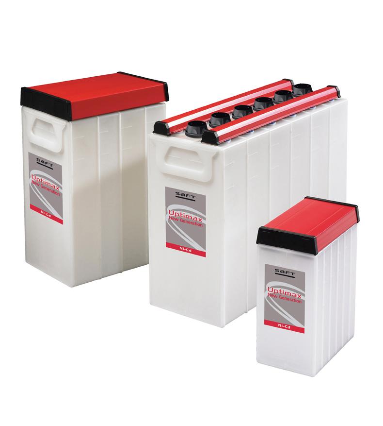
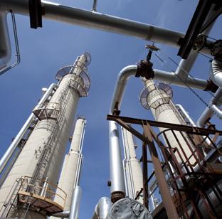
3 1. Introduction The nickel-cadmium battery is the most reliable battery system available in the market today. Its unique features enable it to be used in applications and environments untenable for other widely available battery systems. To offer a highly reliable battery of zero or ultra-low maintenance Saft has developed the Uptimax New Generation maintenance-free pocket plate battery. The term maintenance-free in this publication means that no addition of water is necessary during the lifetime of the product when operated under Saft s recommended conditions. This publication details the design and operating characteristics of the Saft Nife brand Uptimax battery. When operated in recommended conditions, Uptimax New Generation will not require any toppingup during its entire service life. Other regular maintenance checks are still necessary (see section 10 Installation and operating instructions). In addition to all the well-proven advantages of the nickel-cadmium pocket plate battery, Uptimax offers exceptional electrical performance enabling customers to benefit from a smaller battery capacity to suit their specific applications. Saft Uptimax is certified compliant to IEC / IEC battery standards. 2. Applications UPS Process control Emergency systems Security systems Offshore oil and gas Switchgear Uptimax batteries are designed to supply the ideal maintenance-free power backup solution for installations that demand maximum reliability and optimum TCO (Total Cost of Ownership) while operating for long periods at high ambient temperatures. Uptimax is especially suited for the oil and gas, utility and electricity industries where availability and reliability of backup power is essential. 3. Construction features Uptimax New Generation battery Flame-arresting low pressure vent Terminal pillars beneath terminal covers. In line with EN / IEC (safety) with IP2 level Plate group bus bar Plate tab Polypropylene cell container Pocket plate Polypropylene fibrous separator Construction of the Saft Nife brand Uptimax cell is based upon Saft pocket plate technology and a new hightech concept designed to achieve maintenance-free operation in terms of topping-up, improved performance and chargeability. 3.1 Plate assembly The nickel-cadmium cell consists of two groups of plates, one containing nickel hydroxide (the positive plate) and the other containing cadmium hydroxide (the negative plate). Cells are welded together to form rugged blocks up to 10 depending on cell size and type. The active materials of the Saft Uptimax pocket plate are retained in pockets formed from nickel-plated steel strips double-perforated by a patented process. These pockets are mechanically linked together, cut to the size corresponding to the plate width and compressed to 3
4 the final plate dimension. This process leads to a component which is not only mechanically robust but also retains its active material within a steel boundary which promotes conductivity and minimizes electrode swelling. These plates are then welded to a current carrying bus bar which further ensures the mechanical and electrical stability of the product. The alkaline electrolyte does not react with steel, which means that the supporting structure of the Uptimax battery stays intact and unchanged for the life of the battery. There is no corrosion and no risk of sudden death. 3.2 Separator The separator is a key feature of the Uptimax battery. It is a polypropylene fibrous material which has been used and proven by Saft in the Ultima ultra-low maintenance product over more than 20 years and has been further optimized for this product to give the features required. Using this separator, the distance between the plates is carefully controlled to give the necessary gas retention to provide the level of recombination required. By providing a large spacing between the positive and negative plates and a generous quantity of electrolyte between plates, the possibility of thermal runaway is eliminated. 3.3 Electrolyte The electrolyte used in Uptimax, which is a solution of potassium hydroxide and lithium hydroxide, is optimized to give the best combination of performance, life and energy efficiency over a wide operational temperature range. With the Uptimax, as with all nickel cadmium, the electrolyte concentration does not change significantly between a full charged state and a full discharged state. It retains its ability to transfer ions between the cell plates irrespective of the charge level. In most applications the electrolyte will retain its effectiveness for the life of the battery and will never need replacing. There are two types. a) The standard type concentration is such as to allow the cell to be operated to temperature extremes as low as - 20 C (- 4 F) and as high as + 70 C (+ 158 F). This allows the very high temperature fluctuations found in certain remote regions to be accommodated. b) For continuous temperatures below - 20 C (- 4 F) an arctic electrolyte is used. It is a special high density electrolyte. 3.4 Terminal pillars Short terminal pillars are welded to the plate bus bars using a well-proven battery construction method. They are constructed of nickel-plated steel and are internally threaded. The pillar to lid seal uses a compressed visco-elastic sealing method. The pillars are held in place by compression lock washers. This assembly is designed to provide satisfactory sealing throughout the life of the product. 3.5 Venting system Uptimax is fitted with a flame-arresting low-pressure vent for each cell of the battery. This vent operates as a one way valve (as defined in IEC ) which will allow the release of small quantities of hydrogen and non-recombined oxygen. It allows venting if the internal pressure exceeds a fixed safety value. The selfclosing vent has an integral porous disk, for flame-arresting function, to prevent an external ignition from spreading into the Uptimax cell. 3.6 Cell container The Uptimax is built up using the wellproven Saft block battery construction. The tough polypropylene containers are welded together by a heat sealing technique. The assembly of the blocks is completed by a clip-on terminal cover which gives protection to IP2X according to IEC standard for the conductive parts. 4. Principles of the oxygen recombination cycle In a conventional flooded electrolyte pocket plate nickel-cadmium battery water is lost from the battery on overcharge due to the following reactions: At the positive plate 4OH - 2H 2 O + O 2 + 4e- (Oxygen evolution) At the negative plate 4H 2 O + 4e- 2H 2 + 4OH - (Hydrogen evolution) 4 This corresponds to a theoretical loss of 36 g of water for 107 Ah of overcharge i.e cm 3 per Ah. Hence a conventional cell requires periodic addition of water. The frequency of this operation depends upon the cumulative amount of charge received and the operating temperature. During the charging process evolution of oxygen begins to occur a little before the positive plate reaches its fully charged state and then becomes the main reaction when the fully charged condition is reached. However, the cadmium negative plate has a better charge acceptance than the positive plate and hydrogen is not evolved until this plate is virtually fully charged. The oxygen which is produced at the positive plate surface is collected by the special porous separator and thus
5 not allowed to escape from the region between the plates. Some displacement of electrolyte within the separator occurs, thus generating extra unfilled pores for the diffusion of oxygen directly to the adjacent cadmium negative plate. As soon as the oxygen reaches the negative plate it reacts either chemically or electrochemically. In both cases, the oxygen recombination prevents the negative plate from fully charging and in turn it suppresses the evolution of hydrogen gas. In the Uptimax design, the separator and plate stack are optimized to minimize hydrogen evolution and water usage when operated as recommended. This ensures a long service life without the need to replenish with water. The Uptimax recombination is exceeding the IEC minimum requirement level of 70 % and achieves more than 95 %. The Uptimax battery is fitted with a low pressure vent on each cell. On overcharge the cells have an internal pressure above atmospheric pressure. The vent acting as a valve provides an outlet for the release of small quantities of hydrogen and nonrecombined oxygen and thus controls the internal pressure. When the pressure falls below the release pressure either on open circuit or on discharge the vent reseals to prevent ingress of air and to minimise self-discharge reactions. 5. Battery features Complete reliability Does not suffer from the sudden death failure due to internal corrosion associated with other battery technologies. Long cycle life The Uptimax battery has a long cycle life even when the charge/discharge cycle involves 100 % depth of discharge (see section 6.7 Cycling). Exceptionally long floating lifetime A lifetime in excess of twenty years is achieved by Uptimax in many applications, and at elevated temperatures it has a superior life when compared to other available battery technologies. Maintenance-free With its special recombination separator combined with its low pressure vent and generous electrolyte reserve, Uptimax eliminates the need for topping-up with water under recommended operating instructions from - 20 C (- 4 F) to + 40 C (+ 104 F) at 1.42 V/cell with temperature compensation (see section 7.2 Temperature compensation). Note that it is possible to add water if required. Simple installation Uptimax can be used with a wide range of stationary and mobile applications as it produces no corrosive vapors, uses corrosion-free polypropylene containers and has a simple bolted connector assembly system (see section 10 Installation and operating instructions). Wide operating temperature range Uptimax employs an electrolyte which allows a normal operating temperature of from - 20 C to + 40 C (- 4 F to F) and accepts extreme temperatures, ranging from as low as - 40 C with arctic electrolyte to + 70 C (- 40 F to F) (see section 3.3 Electrolyte). Fast recharge/improved chargeability Uptimax can be recharged at high currents which allow very fast recharge times to be achieved (see section 7.4 Charge efficiency). Resistance to mechanical abuse Uptimax is designed with a high mechanical strength. It withstands all the harsh treatment associated with transportation over difficult terrain (see section 8.2 Mechanical abuse). High resistance to electrical abuse Uptimax will survive abuse which would destroy other battery technologies. For example, it can withstand overcharging, deep discharging, and high ripple currents without damage (see section 8.1 Electrical abuse). Well-proven pocket plate construction Saft has nearly 100 years of manufacturing and application experience with respect to the nickel-cadmium pocket plate product. This expertise has been built into the twenty-plus years design life of the Uptimax product (see section 3 Construction features of the Uptimax New Generation battery). Extended storage When stored in the filled and charged state in normal condition (0 C to + 30 C / + 32 F to + 86 F), Uptimax can be stored for up to 2 years (see section 10 Installation and operating instructions). Environmentally safe Saft operates a dedicated recycling center to recover the nickel, cadmium, steel and plastic used in the battery (see section 12 Disposal and recycling). Low life-cycle cost When all the factors of lifetime, low maintenance requirements, simple installation and storage and resistance to abuse are taken into account, Uptimax becomes the most cost effective solution for many professional applications. 5
6 6. Operating characteristics 6.1 Capacity The Uptimax battery capacity is rated in ampere-hours (Ah). Its rated Ah is the quantity of electricity at + 20 C (+ 68 F) which it can supply for a 5 hours runtime to 1.0 V/cell after being fully charged. This is in accordance with both IEC and IEC standard. In accordance with these IEC standards, the current can be expressed as a function of this 5 hours capacity or the C 5 capacity. For example, the expression 0.2 C 5 A is equal to 20 % of the C 5 capacity in Amps. The expression follows the IEC specification since the declared nominal capacity (C n ) is the runtime of 5 hours. So in that case, 100 % of the Ah is delivered in 5 hours of runtime at C 5 /5 A or 0.2 C 5 A. When the discharge current deviates from 0.2 C 5 A so will the delivered capacity or runtime. In practice, Uptimax is used in floating conditions and so the tabular data is based upon cell performance after several months of floating. This eliminates certain correction factors which need to be used when sizing batteries with conventional fully charged open cell data (see section 9 Battery sizing principles). 6.2 Cell voltage The cell voltage of nickel-cadmium cells results from the electrochemical potentials of the nickel and the cadmium active materials in the presence of the potassium hydroxide electrolyte. The nominal cell voltage is 1.2 V. 6.3 Internal resistance The internal resistance of a cell varies with the temperature and the state of charge. In the fully charged state and at high temperature, the internal resistance is the lowest. The internal resistance is characterized by measuring the response in discharge voltage with a change in discharge current. The internal resistance of an Uptimax cell has the values given in the product literature for fully charged cells at normal temperature. For lower states of charge the values increase. At 50 % discharged, the internal resistance is about 20 % higher, and at 90 % discharged, it is about 80 % higher. When the temperature decreases below 20 C, the internal resistance increases. At 0 C (+ 32 F), the internal resistance is about 40 % higher. 6.4 Effect of temperature on performance Variations in ambient temperature affect the performance of Uptimax and this needs to be taken into account when sizing the battery. Low temperature operation reduces the discharge performance but at the high temperature, the discharge performance is similar to those at normal temperatures. Temperature de-rating factors for L and M type cells are given in Figure 1(a) and Figure 1(b) for operating temperature - 20 C to + 40 C (- 4 F to F). Figure 1(a): Temperature de-rating factors for L type cell for cell final voltage 1.00 V De-rating factor Figure 1(b): Typical de-rating factors for M type cell for cell final voltage 1.00 V De-rating factor C - 10 C 0 C + 10 C + 20 C + 30 C + 40 C - 4 F + 14 F + 32 F + 50 F + 68 F + 86 F F 5 hour rate 1 hour rate Temperature Typical de-rating factors for published performance data for cells in floating applications C - 10 C 0 C + 10 C + 20 C + 30 C + 40 C - 4 F + 14 F + 32 F + 50 F + 68 F + 86 F F Temperature 5 hour rate 1 hour rate 30 minute rate Typical de-rating factors for published performance data for cells in floating applications 6
7 6.5 Short-circuit values The typical short-circuit value of an Uptimax cell is given in Table 1. The Uptimax battery is designed to withstand a short-circuit current of this magnitude for many minutes without damage. Table1: Short-circuit currents at + 20 C (+ 68 F) for fully charged cells Type L M Amperes 6 * C 5 A 11* C 5 A 6.6 Open circuit loss The state of charge of Uptimax on open circuit slowly decreases with time due to self-discharge. In practice this decrease is relatively rapid during the first two weeks but then stabilizes to about 2 % per month at + 20 C (+ 68 F). The self-discharge is affected by the temperature. At low temperatures the selfdischarge decreases and so the open circuit loss is reduced. At high temperature the self-discharge is increased and the open circuit loss is also increased. The open circuit loss for Uptimax is shown in Figure 2 for a one year period. 6.7 Cycling Uptimax is a maintenance-free product when used under recommended conditions in stationary and not continuous cycling applications. Nevertheless, it is designed using conventional pocket plate electrode technology and has therefore an equivalent cycling capability. If Uptimax is used in a continuous cycling application, the water consumption may be significantly increased. In that case, watering the cells during their useful life will be necessary. However, there are cycling applications where Uptimax can be beneficial. This will depend on the frequency and depth of discharge Table 2: Values for current I gas producing gas when charging at constant current or potential Igas (ma/ah) Under float charge conditions 1.42 V/cell 2 Under boost charge conditions 1.45 V/cell 5 Under all commissioning charge conditions Constant current charge and constant potential charge 200 involved. For example, in a poor power quality stationary application, the Uptimax battery can provide superior cycling duty with infrequent or no watering intervals (see section 8). 6.8 Water consumption The Uptimax battery works on the oxygen recombination principle and therefore has a reduced water consumption. The Uptimax recombines at least at a level of 95 % when float charging (as per IEC methodology). It has a water usage reduced by a factor of up to 10 times of that of an open flooded cell. When operated as recommended, the Uptimax will not need topping-up during its entire service life. 6.9 Gas evolution Gas is generated during overcharge through electrolysis when gas doesn t recombine, it will eventually exhaust from the cell. The electrolysis of 1 cm 3 of water produces about 1865 cm 3 of gas mixture and this gas mixture is in the proportion of 2/3 hydrogen and 1/3 oxygen. Thus the electrolysis of 1 cm 3 of water produces about 1243 cm 3 of hydrogen. Table 2 gives the values for I gas used to estimate ventilation needs in accordance with IEC / EN Figure 2: Typical open circuit loss variation with time 110 Percentage of initial capacity % Open circuit period (days) + 40ºC (+ 104ºF) + 20ºC (+ 68ºF) 0ºC (+ 32ºF) 7
8 7. Battery charging In order to ensure that the maintenancefree properties of the Uptimax battery are achieved, it is necessary to control the charge input to the battery to optimize the rate of water loss during the life of the product. The Uptimax battery must be properly commissioned (see section 10) before putting in service and applying the following charging methods. It is important therefore that the recommended charge conditions are complied with. 7.1 In service charging methods The single level float charging method is adequate to maintain the Uptimax in a good state of operation over its useful life. It should not be required to implement a two level constant potential charging method if Uptimax is used in a stationary power application and the installation, commissioning and operation is done in accordance with Saft Installation and Operating instructions (see section 10). Uptimax batteries may be charged quickly and simply by the following methods: a) Two level constant potential charging The initial stage of two-rate constant potential charging consists of a first charging stage to a maximum voltage of 1.45 ± 0.01 V/cell. Up to 12 hours of recharge time with this initial stage of charge is necessary when fully discharged. 8 After this first stage the charger should be switched to a second maintenance stage at a float voltage of 1.42 ± 0.01 V/cell. After a prolonged mains failure the first stage should be reapplied manually or automatically. b) Single level float charging Uptimax batteries are float charged at 1.42 ± 0.01 V/cell from a fully discharged condition to a high state of charge. This is detailed in section 7.2. Temperature compensation is required to avoid the need for water topping over its useful life. 7.2 Temperature compensation At + 20 C (+ 68 F) and at a fixed voltage of 1.42 VPC, Uptimax operates with an optimized balance between stabilized state of charge (SOC) and water consumption. Uptimax gives, in this case, the highest performance and no watering maintenance benefits over its useful life. In order to maintain this optimized condition in standby operation, Temperature Compensated Voltage (TCV) control is mandatory. When the temperature increases above + 20 C (+ 68 F) at a fixed voltage, the float current increases, the charge efficiency decreases and the water consumption increases. As a result, to maintain an optimized balance between state of charge (SOC) and water consumption, the voltage should decrease. Table 3: Temperature Compensated Voltage (TCV) control as a function of temperature for dual and single method Control method Dual Single VPC (Volt Per Cell) < + 20 C (+ 68 F) > + 20 C (+ 68 F) T ( C) T ( F) -3.0 mv / C / Cell -2.0 mv / C / Cell -2.5 mv / C / Cell (-1.68 mv / F / Cell) (-1.12 mv / F / Cell) (-1.4 mv / F / Cell) When the temperature decreases below + 20 C (+ 68 F), at a fixed voltage, the reverse occurs, i.e. the float current decreases, the charge efficiency increases and the water consumption decreases. As a result, to maintain an optimized balance between state of charge (SOC) and water consumption the voltage should increase. When the temperature increases, then the electrochemical behaviour becomes more active and so, for the same charge voltage, the current at the end of charge increases. This increases the water usage. For this reason it is recommended to operate with Temperature Compensated Voltage (TCV) control active. Water consumption, when operating at high temperatures, is reduced allowing the Uptimax to operate without the need of watering maintenance over its useful life. When operating at low temperatures, the reverse occurs. For that reason it is recommended to operate with Temperature Compensated Voltage (TCV) control in order to increase the charge current. This control contributes to maintaining a high state of charge and in turn an acceptable level of discharge performance. Table 3 gives the TCV control slopes according to the temperature in dual and single control method. In dual control, the TCV control slopes are different below and above + 20 C (+ 68 F). If only one TCV control can be implemented then use the slope that corresponds best with the temperature range expected in the application. In single control, the TCV slope is the same below and above + 20 C (+ 68 F). If no TCV control is available, operate with a fixed voltage set point of 1.42 V/cell.
9 7.3 Charge acceptance The performance data sheets for Uptimax are based upon several months floating and so are for fully float charged cells. A discharged cell will take a certain time to achieve the state of charge. Figure 3 gives the available capacity during charge. For stationary application, the recommended charge voltage is 1.42 ± 0.01 V for floating and 1.45 ± 0.01 V for the first stage of a two step charge. Up to 0.2C 5 A of recharge current can be used. A full state of charge will be reached in 1 to 3 months. 7.4 Charge efficiency The charge efficiency of Uptimax is dependent on the state of charge of the battery and the temperature. For much of its charge profile it is recharged at a high level of efficiency. In general, at states of charge less than 80 % the charge efficiency remains high. When the battery approaches a fully charged condition, the charging efficiency decreases rapidly until fully charged when overcharge begins. Figure 3(a): Available capacity after constant voltage charge Available charge current 0.1C 5 A or 0.2C 5 A, for L type cell. % of rated capacity Figure 3(b): Available capacity after constant voltage charge Available charge current 0.1C 5 A or 0.2C 5 A, for M type cell. % of rated capacity Charging time (hours) 1.45 Vpc at + 20ºC (+ 68ºF), 0.2C 5 A 1.45 Vpc at + 20ºC (+ 68ºF), 0.1C 5 A 1.42 Vpc at + 20ºC (+ 68ºF), 0.1C 5 A * For charging voltages higher than 1.45 V/cell, a current limit of 0.1 C 5 A is recommended Charging time (hours) 1.45 Vpc at + 20ºC (+ 68ºF), 0.2C 5 A 1.45 Vpc at + 20ºC (+ 68ºF), 0.1C 5 A 1.42 Vpc at + 20ºC (+ 68ºF), 0.1C 5 A * For charging voltages higher than 1.45 V/cell, a current limit of 0.1 C 5 A is recommended 8. Special operating factors 8.1 Electrical abuse Ripple effects The nickel-cadmium battery is tolerant to high ripple from standard charging systems. Uptimax accepts ripple currents up to 0.2 C 5 A I eff. In general, any commercially available charger or generator can be used for commissioning or maintenance charging of Uptimax Over-discharge If more than the designed capacity is taken out of a battery then it becomes overdischarged. This is considered to be an abuse situation for a battery and should be avoided. However, the Uptimax battery is designed to recover from this situation Overcharge Overcharge is the effect of forcing current through a battery when it is fully charged. In the case of Uptimax, with its generous electrolyte reserve, a small degree of overcharge will not significantly alter the maintenance period. In the case of excessive overcharge or excessive cycling, water replenishment may be required but there will be no significant effect on the life of the battery. 8.2 Mechanical abuse Shock loads The Uptimax block battery concept complies with IEC (bump tests at 5 g, 10 g and 25 g) and IEC (shock test 3 g), where g = acceleration Vibration resistance The Uptimax block battery concept complies with IEC where it was subjected to 2 hours at 1 g, where g = acceleration External corrosion Uptimax nickel-cadmium cells are manufactured in durable polypropylene, all external metal components are nickel-plated and these components are protected by an anti-corrosion oil and a rigid plastic cover. 9
10 9. Battery sizing principles in stationary applications There are a number of methods which are used to size nickel-cadmium batteries for standby floating applications. The method employed by Saft is the IEEE 1115 recommendation which is accepted internationally. This method takes into account multiple discharges, temperature de-rating, performance after floating and the voltage window available for the battery. A significant advantage of the nickelcadmium battery is that it can be fully discharged without a significant impact in terms of life or recharge. Thus, to obtain the most cost efficient battery, it is an advantage to discharge the battery to the lowest practical value in order to obtain the maximum energy from the battery. The principle sizing parameters are: 9.1 The voltage window This is the maximum voltage and the minimum voltage at the battery terminals acceptable for the system. In battery terms, the maximum voltage gives the voltage which is available to charge the battery, and the minimum voltage gives the lowest voltage acceptable to the system to which the battery can be discharged. In discharging the nickelcadmium battery, the cell voltage should be taken as low as possible in order to find the most economic and efficient battery. 9.2 Discharge profile This is the electrical performance required from the battery for the application. It may be expressed in terms of amperes for a certain duration, or it may be expressed in terms of power (watts or kw) for a certain duration. The requirement may be simply a one step discharge or a many step profile. In order to utilize all of the charged capacity, it s recommended to discharge the battery until 1.00 V/Cell Temperature The maximum and minimum temperatures and the normal ambient temperature will have an influence on the sizing of the battery. The performance of a battery decreases with decreasing temperature which increases the battery size. Temperature de-rating curves are provided to allow sizing adjustments. 9.4 State of charge or recharge time Some applications may require that the battery shall give a full duty cycle after a certain time after the previous discharge. The factors used for this will depend on the depth of discharge, the rate of discharge, and the charge voltage and current. A requirement for a high state of charge does not justify a high charge voltage if the result is a high end of discharge voltage. 9.5 Ageing Some customers require a value to be added to allow for the ageing of the battery over its lifetime. This may be a value required by the customer, for example 10 %, or it may be a requirement from the customer that a value is used which will ensure the service of the battery during its lifetime. The value to be used will depend on the discharge rate of the battery and the conditions under which the discharge is carried out. 9.6 Floating effect When a nickel-cadmium cell is maintained at a fixed floating voltage over a period of time, there is a decrease in the voltage level of the discharge curve. This effect begins after one week and reaches its maximum in about 3 months. It can only be eliminated by a full discharge/ charge cycle, and it cannot be eliminated by a boost charge. It is therefore necessary to take this into account in any calculations concerning batteries in float applications. This is used in the IEEE sizing method and is included in the published data for Uptimax. As the effect of reducing the voltage level is to reduce the autonomy of the battery, the effect can be considered as reducing the performance of the battery and so performance down-rating factors are used. Note: for your battery sizing needs, please contact your local sales representative.
11 10. Installation and operating instructions Type UP1 L and UP1 M Important recommendations Never allow an exposed flame or spark near the batteries, particularly while charging. Never smoke while performing any operation on the battery. For protection, wear rubber gloves, long sleeves, and appropriate splash goggles or face shield. The electrolyte is harmful to skin and eyes. In the event of contact with skin or eyes, wash immediately with plenty of water. If eyes are affected, flush with water, and obtain immediate medical attention. Remove all rings, watches and other items with metal parts before working on the battery. Use insulated tools. Avoid static electricity and take measures for protection against electric shocks. Discharge any possible static electricity from clothing and/or tools by touching an earth-connected part ground before working on the battery Receiving the shipment Upon receipt of the goods, any transportation damage, electrolyte spillage or irregularities must be reported to the carrier and to Saft. The battery is shipped filled and charged, and is ready for immediate use. Storage of cells must not exceed the maximum storage time indicated on the packing case (first in, first out) Storage The battery must be stored in a dry indoor location, on open, well ventilated shelves away from direct sunlight between 0 C and + 30 C (+ 32 F and 86 F). Uptimax batteries are supplied filled with electrolyte and charged. They can be stored in this condition for maximum 24 months from date of shipment in accordance with the recommendations set forth in this technical manual. Storage of a filled battery at temperatures above + 30 C (+ 86 F) can result in permanent change and loss of product performance, depending on the duration of the storage above the maximum recommended temperature. Never drain the electrolyte from the cells. To ensure maximum protection of the cells always store the product in its original packaging Installation Location Install the battery in a dry and clean room. Avoid direct sunlight and heat. The battery will give the best performance and maximum service life when the ambient temperature is between + 10 C to + 30 C (+ 50 F to + 86 F) Mounting Verify that cells are correctly interconnected with the appropriate polarity. The battery connection to load should be with nickel-plated cable lugs. Recommended torques for terminal bolts are: M6 = 11 ± 1.1 N.m (97.4 ± 9.8 lbf.in) M8 = 20 ± 2 N.m (177.0 ± 17.7 lbf.in) M10 = 30 ± 3 N.m (265.0 ± 26.6 lbf.in) Protect connectors and terminals against the corrosion with a thin layer of NO-OX- ID A or neutral anti-corrosion oil, approved by Saft Ventilation During operation the battery emits an amount of gas mixture (oxygen and hydrogen). Ventilation inside the battery room must be adequately managed, comply with IEC / EN and local regulations Electrolyte When checking electrolyte levels, a fluctuation in level between cells is normal. This is caused by a small difference in internal pressure in each cell. Normally there is no need to adjust the electrolyte level. If the level is 30 mm (1.2 ) below the minimum level mark the affected product must be topped up using Saft s E22 electrolyte. Do not top-up cells prior to an initial charge. After commissioning, when the level is stabilized, the electrolyte level should be between the maximum mark and 5 mm below Commissioning Commissioning the battery is important: Charging at constant current is preferable. If the current limit is lower than indicated in the Installation & Operating Instruction (Table A), extend the charge time proportionally. 11
12 Cells stored up to 6 months: A commissioning charge is normally not required and the cells are ready for immediate use. However, the product s full performance will only be achievable after 1-3 months of charging in service (see section 7.3 Charge acceptance. If the published performance is required immediately, please refer to the procedure dedicated to cells stored more than 6 months and up to 2 years. Cells stored more than 6 months and up to 2 years: A commissioning charge is necessary: Commissioning at ambient temperature 12 between + 10 C to + 30 C (+ 50 F to + 86 F) - Constant current charge: 10 h at 0.2 C 5 A recommended. Notice: At the end of charge the cell voltage will reach about 1.80 V, thus the charger shall be able to supply such a voltage. When the charger maximum voltage setting is too low to supply constant current charging, divide the battery into two parts to be charged individually at constant current. - Constant potential charge: 1.55 V/cell for a minimum of 24 h with current limited 0.2 C 5 A. If these methods are not available, then charging may be carried out at lower voltages, 1.50 V/cell for 36 h minimum. Commissioning at ambient temperature above + 30 C (+ 86 F) - Only constant current charge: 10 h at 0.2 C 5 A recommended. The electrolyte temperature is to be monitored during charge. If the temperature exceeds + 45 C (+ 113 F) during charging, then it must be stopped to reduce the temperature. The charging can be resumed when electrolyte temperature drops below + 40 C (+ 104 F). When full battery performance is required for capacity test purposes, the cells shall be tested in accordance with IEC Charging in service The recommended charging voltages for continuous parallel operation, with occasional battery discharges, are: Two level charge: float level: 1.42 ± 0.01 V/cell high rate (boost) level: 1.45 ± 0.01 V/cell Single level charge: 1.42 ± 0.01 V/cell To achieve maintenance-free operation, in terms of topping-up, at high temperatures, a correction factor of -2.0 mv/ C (-1.12 mv/ F) is mandatory, starting from an ambient temperature of 20 C (68 F). For other conditions, see section 7.2 Temperature compensation Periodic maintenance Uptimax is a maintenance-free battery under the recommended operating conditions, from - 20 C (- 4 F) to + 40 C (+ 104 F) at 1.42 V/cell, with temperature compensation and requires only preventive maintenance. Best practices include keeping the battery clean using only water. Do not use a wire brush or solvents of any kind. Individual cell and total battery charge voltage must be checked and recorded once per year. Individual cells with voltages measured below 1.30 V during float charge must receive corrective action. Please refer to Section Check visually the electrolyte level. Never let the level fall below the minimum level mark. Use only distilled or de-ionized water to top-up. Topping-up of the Uptimax battery shall be carried out when battery is fully charged. Changing or measuring the electrolyte specific gravity is not required. Check all connections are tight every two years. Tightening torque for the terminals must be: M 6 = 11 ± 1.1 N.m (97.4 ± 9.8 lbf.in) M 8 = 20 ± 2.0 N.m (177.0 ± 17.7 lbf.in) M10 = 30 ± 3.0 N.m (265.0 ± 26.6 lbf.in). Protect connectors and terminals against the corrosion with a thin layer of NO-OX-ID A or neutral anti-corrosion oil, approved by Saft. To maximise the topping-up interval check the charging voltage and adjust as required.
13 11. Troubleshooting 11.1 Troubleshooting procedures Symptom Check Possible cause Action The battery does not supply required energy or power Excessive water consumption Low or no water consumption Identify the last operation performed by the battery Check battery charge voltage Check individual cell voltage Check battery charge voltage Check individual cell voltage Battery has been discharged and not re-charged Charge voltage too low Cell in partial or total shortcircuit Charge voltage too high Cell in partial or total shortcircuit Wait until the battery is recharged. Refer to Section 7.3 in this manual Adjust the charging voltage according to Section 10.5 If a cell float voltage is found below 1.30 V, high rate charge is recommended to apply to the cell concerned. See Section 10.6 Adjust the charger voltage according to Section 10.5 If a cell float voltage is found below 1.30 V, high rate charge is recommended to apply to the cell concerned. See Section 10.6 Check charger log Frequent discharge/recharge Check power supply to charger Check battery charge voltage Check connections to and on the battery Charge voltage too low Loose connector Ground fault Visual inspection of the battery Wet and dirty battery Adjust the charger voltage according to Section 10.5 Retorque connector according to Section 10.3 Clean the battery using only water and wipe it off with a soft and clean cloth For further information contact Saft 13
14 12. Disposal and recycling In a world where autonomous sources of electric power are ever more in demand, Saft batteries provide an environmentally responsible answer to these needs. Environmental management lies at the core of Saft s business and we take care to control every stage of a battery s life cycle in terms of potential impact. Environmental protection is our top priority, from design and production through end-of-life collection, disposal and recycling. Our respect for the environment is complemented by an equal respect for our customers. We aim to generate confidence in our products, not only from a functional standpoint, but also in terms of the environmental safeguards that are built into their life cycle. The simple and unique nature of the battery components make them readily recyclable and this process safeguards valuable natural resources for future generations. Pure cadmium New batteries Battery use Distillation Spent batteries Cadmium plates Dismantling Ferro nickel Steel works Nickel plates Standards list: Certified IEC Secondary cells and batteries containing alkaline or other non-acid electrolytes - Nickel-cadmium prismatic secondary single cells with partial gas recombination. Uptimax New Generation exceeds gas recombination requirements. Certified IEC Secondary cells and battery containing alkaline and other non-acid electrolytes - Vented nickel-cadmium prismatic secondary single cells IEC Environmental testing - Part 2: Tests. Test Eb and guidance: Bump IEC Environmental testing - Part 2-77: Tests - Test 77: Body strength and impact shock IEC International electro technical vocabulary - Part 482: Primary and secondary cells and batteries Complies with EN / IEC Safety requirements for secondary batteries and battery installations - Part 2: Stationary batteries - The protective covers for terminals and connectors, the insulated cables are compliant with IP2 level protection against electrical shocks according to safety standard. IEEE IEEE Recommended practice for sizing Nickel-Cadmium batteries for stationary applications 14


15 Saft is committed to the highest standards of environmental stewardship As part of its environmental commitment, Saft gives priority to recycled raw materials over virgin raw materials, reduces its plants air and water releases year after year, minimizes water usage, reduces fossil energy consumption and associated CO 2 emissions, and ensures that its customers have recycling solutions for their spent batteries. Regarding industrial nickel-based batteries, Saft has had partnerships for many years with collection companies in most EU countries. This collection network receives and dispatches our customers batteries at the end of their lives to fully approved recycling facilities, in compliance with the laws governing trans boundary waste shipments. This collection network meets the requirements of the EU batteries directive. A list of our collection points is available on our web site. In other countries, Saft assists users of its batteries in finding environmentally sound recycling solutions. Please contact your sales representative for further information. Saft 12, rue Sadi Carnot Bagnolet - France Tel. : Fax : Doc No.: Edition: June 2016 Data in this document is subject to change without notice and becomes contractual only after written confirmation. Photo credits: Saft, Fotolia Produced in the UK by Arthur Associates Limited Société par Actions Simplifiée au capital de RCS Bobigny B
Uptimax New Generation Ni-Cd battery. Maintenance-free solution for backup power applications
 NiCd battery Maintenancefree solution for backup power applications The ideal choice for total security and availability Saft your trusted battery partner for stationary applications Saft has over years
Uptimax New Generation Ni-Cd battery. Maintenance-free solution for backup power applications
 NiCd battery Maintenancefree solution for backup power applications The ideal choice for total security and availability Saft your trusted battery partner for stationary applications Saft has over years
Uptimax New Generation Ni-Cd battery. Maintenance-free solution for backup power applications
 NiCd battery Maintenancefree solution for backup power applications The ideal choice for total security and availability Saft your trusted battery partner for stationary applications Saft has over 100
V3.4. Vantage. Ultra-low maintenance batteries. Technical manual
 V3.4 Vantage Ultra-low maintenance batteries Technical manual Contents 1 Introduction 3 2 Benefits of the Vantage battery 4 3 Battery applications 5 4 Principles of the oxygen recombination cycle 6 5 Construction
Valve Regulated Pocket Plate Nickel Cadmium Battery. Technical Manual
 Valve Regulated Pocket Plate Nickel Cadmium Battery Technical Manual Contents Pages 1.0. Introduction to VRPP battery 2.0. VRPP - Solution to varied applications 3.0. xygen recombination cycle - A technological
Sunica.plus Technical manual
 Sunica.plus Technical manual Contents 1. Introduction 4 2. The photovoltaic application 4 3. Sunica.plus construction 3.1. Plate assembly 5 3.2. Separator 6 3.3. Electrolyte 6 3.4. Terminal pillars 6 3.5.
Ni-Cd block battery. Technical manual. August 2018
 Ni-Cd block battery Technical manual August 2018 Contents 1. Introduction 3 2. Benefits of the block battery 4 2.1 Complete reliability 4 2.2 Long cycle life 4 2.3 Exceptionally long lifetime 4 2.4 Low
Single Cell Range Technical manual
 S3.4 April 2007 Single Cell Range Technical manual Contents Single Cell Range 1. Introduction 3 2. Benefits of the Alcad pocket plate Ni-Cd battery 4 2.1 Complete reliability 4 2.2 Long cycle life 4 2.3
Single Cell Range Technical manual
 S3.5 April 2012 Single Cell Range Technical manual Contents Single Cell Range 1. Introduction 3 2. Benefits of the Alcad pocket plate Ni-Cd battery 4 2.1 Complete reliability 4 2.2 Long cycle life 4 2.3
ULTIMA Ni-Cd BATTERY: PEAK PERFORMANCE WITH ULTRA LOW MAINTENANCE
 ULTIMA Ni-Cd BATTERY: PEAK PERFORMANCE WITH ULTRA LOW MAINTENANCE ULTRA LOW MAINTENANCE Ni-Cd FOR WHEN SAFETY CANNOT BE COMPROMISED Developed in line with long proven nickel-cadmium technology, the Ultima
Ni-Cd BLOCK BATTERY TECHNICAL MANUAL
 Ni-Cd BLOCK BATTERY TECHNICAL MANUAL Contents 1. Introduction 3 2. Benefits of the block battery 4 2.1 Complete reliability 4 2.2 Long cycle life 4 2.3 Exceptionally long lifetime 4 2.4 Low maintenance
Nickel Cadmium Batteries BLOCK TYPE
 Nickel Cadmium Batteries BLOCK TYPE POWER BACK-UP WITH NICA NICA your long term partner for power back-up challenges Nica has been a trusted battery for the world s leading industrial players for over
Vantage Ultra-low maintenance batteries
 Ultra-low maintenance batteries V2.6 Ultra-low maintenance batteries Ultra-high reliability, ultra-low maintenance Alcad a powerful combination of proven pocket-plate construction and advanced design from
Saft telecom batteries
 Saft telecom batteries A direct connection to innovation Saft batteries offer the innovation needed for today s telecom applications Meeting a wide range of telecom needs with high performance solutions
Solar Range Technical manual
 P3.1 October 2007 Solar Range Technical manual Solar Range Contents 1. Introduction 3 2. The photovoltaic application 4 3. Construction features of the Alcad Solar battery 5 3.1 Plate assembly 6 3.2 Separation
Vented fibre structure Nickel Cadmium batteries for stationary systems
 Vented fibre structure Nickel Cadmium batteries for stationary systems FNC FNC Vented Nickel Cadmium Batteries the best solution for long, reliable battery life FNC Nickel Cadmium single cells are designed
Vantage ultra-low maintenance batteries
 Vantage ultra-low maintenance batteries V2. Vantage ultra-low maintenance batteries Ultra-high reliability, ultra-low maintenance Introducing Alcad Vantage a powerful combination of proven pocket-plate
Ultima NiCd battery Technical Manual
 Ultima NiCd battery Technical Manual Contents 1. Introduction 1 2. Battery applications 2 3. Ultima range and performances 3 4. Principles of oxygen recombination cycle 6 5. Construction features of the
Industrial Standby batteries. A wide offer of reliable, long-life solutions
 Industrial Standby batteries A wide offer of reliable, long-life solutions Saft stationary batteries, solutions you can count on By providing a large choice of technologies and cell configurations as well
SCL P - SCM Ni-Cd single cells Capacity: 10 Ah to 70 Ah
 SCL P - SCM Ni-Cd single cells Capacity: 10 Ah to 70 Ah Nickel-cadmium single cells are designed for general purpose applications, where maximum operating reliability is a key factor: switch tripping emergency
XHP Low maintenance high performance batteries Technical manual
 X3.3 April 2007 XHP Low maintenance high performance batteries Technical manual Contents XHP Range 1. Introduction 3 2. Electrochemistry of Ni-Cd batteries 4 3. Construction features of the XHP battery
Range. Alcad Single Cell Range. Powerful assurance for maximum operating reliability
 inglecell Range Alcad Single Cell Range Powerful assurance for maximum operating reliability Alcad Single Cell Range the reliability you need at the heart of your power backup system. Versatility for industry
Product Guide. An Invensys company
 Product Guide An Invensys company Contents Introduction Introduction 2 Range Summary 3 Technology 4 Construction 5 Selection of Battery Size 6 Performance Data 7-26 Operating Characteristics 27 Operating
PRODUCT GUIDE Publication No: EN-SBS-PG-001 February 2003
 PRODUCT GUIDE Publication No: EN-SBS-PG-001 February 2003 Contents Introduction Introduction 2 Range Summary 3 Recombination Technology 4 Construction 5 Features and Benefits 6 Battery Sizing 7-8 Performance
NCPP. Nickel Cadmium Pocket Plate Batteries. Block Cell Dimensional and Electrical Data
 NCPP Nickel Cadmium Pocket Plate Batteries Block Cell Dimensional and Electrical Data Nickel Cadmium Pocket Plate Batteries HBL's Nickel Cadmium Pocket Plate Battery designs are based on the superior Pocket
Why Ni-Cd batteries are superior to VRLA batteries. Statements and facts
 Why Ni-Cd batteries are superior to VRLA batteries Statements and facts 1. Maintenance Maintenance for VLRA batteries leads to higher costs than for nickelcadmium batteries. 2. Lifetime In practice, the
Saft railway batteries. Solutions for a world in motion
 Saft railway batteries Solutions for a world in motion Performance and reliability perfected for railway applications Meeting the challenges of the modern railway industry Saft has over 60 years of experience
LDP MP. Ni-Cd single cells. LD P - M P ranges Capacity: 10 Ah to 70 Ah L2.4. Benefits
 L2.4 Ni-Cd single cells LD P - M P ranges Capacity: 10 Ah to 70 Ah LDP MP Nickel-cadmium single cells are designed for general purpose applications, where maximum operating reliability is a key factor:
Tel.X Ni-Cd batteries for telecom networks Technical manual
 Tel.X Ni-Cd batteries for telecom networks Technical manual March 2013 Contents 1 Introduction...5 2 Electrochemical principles...5 3 Tel.X construction...6 3.1 Cells and modules...6 3.2 Battery string...7
Acme NonStop Power. FNC Cell Technology Sealed fiber nickel-cadmium battery systems For commercial, military and space systems.
 Acme Aerospace Inc., manufactures power supplies and high-performance, sealed FNC batteries for military and commercial aerospace, as well as industrial and satellite/ space applications. Acme NonStop
Alpha Lomain Ni-Cd Pocket Plate Battery Technical Manual. Effective: July Alpha Technologies
 Alpha Lomain Ni-Cd Pocket Plate Battery Technical Manual Effective: July 2009 Alpha Technologies Power Alpha Technologies Alpha Lomain Ni-Cd Pocket Plate Battery Technical Manual 745-680-B10-001, Rev.
Ultima SLM Ni-Cd battery Performance with ultra low maintenance
 Ultima SLM Ni-Cd battery Performance with ultra low maintenance July 2004 2 Ultima Ni-Cd battery Ultra low maintenance Developed in line with long proven nickel-cadmium technology, Ultima is an exceptionally
Acme NonStop Power. FNC Cell Technology
 Acme NonStop Power................................................................................................................ FNC Cell Technology Sealed fiber nickel-cadmium battery systems For commercial,
Single Cell Range including LCE P LBE P
 S2.7 April 2007 Single Range including LCE P LBE P Single Range Alcad have nearly 100 years experience in the development and manufacture of pocket plate cells and batteries. Today, they offer the widest
Deep Cycle Battery Safety. First. Battery Handling, Maintenance & Test Procedures
 Deep Cycle Battery Safety. First. Battery Handling, Maintenance & Test Procedures Crown deep cycle batteries employ a low-maintenance design. They do require periodic maintenance and effective charging
POWER FOR TOMORROW. Motive Power. Network Power. Chargers. Bloc Batteries. Accessories. Service
 POWER FOR TOMORROW TODAY The Eternity Technologies range is built using only the highest quality and most efficient production processes at our state-of-the-art manufacturing centre in the UAE. It is this
Chapter 6. Batteries. Types and Characteristics Functions and Features Specifications and Ratings Jim Dunlop Solar
 Chapter 6 Batteries Types and Characteristics Functions and Features Specifications and Ratings 2012 Jim Dunlop Solar Overview Describing why batteries are used in PV systems. Identifying the basic components
RELIABILITY Power Systems Ni-Cd Batteries Div. DS Ver.3.11/ Jan 2011 Page 1/20
 RELIABILITY Power Systems Ni-Cd Batteries Div. DS Ver.3.11/ Jan 2011 Page 1/20 RELIABILITY NICKEL CADMIUM BATTERIES Owing to the structural materials they use, RELIABILITY Nickel Cadmium (Ni-Cd) Batteries
IEEE IAS Atlanta Chapter
 Stationary Battery Sizing IEEE IAS Atlanta Chapter Presented by: Lesley Varga, P.E. Quality Standby Services, LLC 1649 Sands Place, SE, Suite C Marietta, GA 30067 (770) 916-1747 lesley@qualitystandbyservices.com
FIAMM Industrial Batteries December 2012 FIAMM AGM Valve Regulated Recombination Batteries: FLX Series- Engineering Manual TABLE OF CONTENTS
 TABLE OF CONTENTS PAGE 1 OPERATING CHARACTERISTICS 2 2 INSTALLATION 4 3 CHARGING 6 4 STORAGE AND REFRESH CHARGING 8 5 MAINTENANCE AND TESTING 9 6 SAFETY 10 7 APPLICABLE STANDARDS 10 8 RECORDS DATA 10 FIAMM.
NorthStar Battery Company DCN: SES DCR: 1548-S09 Date:
 Application Manual and Product Information for NorthStar Battery Company Table of Contents Introduction...3 NSB Blue Series Benefits...4 ISO Certifications...5 NSB Blue Product Specifications...6 Leak
Product Guide. An Invensys company
 Product Guide An Invensys company Contents Page I/ The principle of the gas-recombination battery... 2 II/ Charge characteristics... 4 III/ Electrical performance tables... 5 IV/ Battery calculations Float
Batteries and more. Powered by (CE, UL & ISO9001 APPROVAL)
") Batteries and more Powered by (CE, UL & ISO9001 APPROVAL) 1. Feature 1) Maintenance free-operation. There is no need to check the special gravity of the electrolyte or to add water during the service life.
Batteries and more Powered by (CE, UL & ISO9001 APPROVAL) 1. Feature 1) Maintenance free-operation. There is no need to check the special gravity of the electrolyte or to add water during the service life.
SPA AGM VRLA batteries
 SPA AGM VRLA batteries for Stationary Applications SPA OVERVIEW Valve Regulated AGM batteries The SPA range of SUNLIGHT Valve Regulated Lead Acid batteries has been developed as general purpose batteries,
Pure Lead-Tin Technology
 Pure Lead-Tin Technology Pure Lead-Tin technology offers many advantages which include: High overall efficiency High energy density Excellent high rate performance Excellent low temperature performance
Uptimax Ni-Cd battery High reliability with low maintenance
 Uptimax Ni-Cd battery High reliability with low maintenance June 2008 The Uptimax solution low maintenance for high temperatures Saft s new Uptimax battery offers the ideal low maintenance battery solution.
VRPP. Nickel Cadmium Valve regulated Pocket Plate Batteries. Dimensional and Electrical Data
 VRPP Nickel Cadmium Valve regulated Pocket Plate Batteries Dimensional and Electrical Data The Valve Regulated Pocket Plate (VRPP) battery combines the unmatched reliability of Nickel Cadmium pocket plate
Power to keep you on the move
 Power to keep you on the move Electric Vehicle Gel ELECTRIC VEHICLE applications are wide and varied with many durability & power demands placed firmly on the batteries shoulders. HAZE ELECTRIC VEHICLE
F R O N T T E R M I N A L PRODUCT GUIDE Publication No: EN-VFT-PG-001 February 2003
 F R O N T T R M I N L PRODUCT GUID Contents Introduction Introduction 2 Range Summary 3 Technology 4 Construction 5 Selection of Battery Size 6 Performance Data 7-14 Operating Characteristics 15 Operating
VentPro Reduced Maintenance Nickel Cadmium Batteries for Stationary Applications
 VentPro Reduced Maintenance Nickel Cadmium Batteries for Stationary Applications Dimensional and Electrical Data Rev. 02-16 Storage Battery Systems LLC N56 W16665 Ridgewood Dr. Menomonee Falls, WI 53051
Air-depolarized industrial batteries
 Air-depolarized industrial batteries THE BATTERY COMPANY T wo air-depolarized battery technologies Saft air-depolarized batteries provide simple, reliable, secure and economical energy with complete operational
XHP. Low maintenance high performance batteries
 Low maintenance high performance batteries Range Low maintenance, high performance Ni-Cd batteries Powerful assurance for critical applications Depend upon where vital UPS, engine starting and emergency
Charge Voltage(V/cell) Set point (V) (V)
 Set point (V) (V)") Temperature compensation is not necessary when the battery is charged at an ambient temperature of 5 (41 F) to 35 (95 F). At a temperature below 5 (41 F) or above 35 (95 F), however, temperature compensation
Temperature compensation is not necessary when the battery is charged at an ambient temperature of 5 (41 F) to 35 (95 F). At a temperature below 5 (41 F) or above 35 (95 F), however, temperature compensation
NCPP. Nickel Cadmium Pocket Plate Batteries. Single Cell Dimensional and Electrical Data
 NCPP Nickel Cadmium Pocket Plate Batteries Single Cell Dimensional and Electrical Data Nickel Cadmium Pocket Plate Batteries HBL's Nickel Cadmium Pocket Plate Battery designs are based on the superior
FLUSH EYES IMMEDIATELY WITH WATER. GET MEDICAL HELP FAST. SULFURIC ACID CAN CAUSE BLINDNESS OR SEVERE BURNS.
 8A & 8G BATTERY INSTALLATION AND OPERATING INSTRUCTIONS This manual is intended to be a guide to optimize battery performance for multiple cyclic & float applications. Consult applicable User Manuals for
POWER-plus. Ni-Cd XHP. Capacity: 10 Ah to 250 Ah
 Ni-Cd XHP Capacity: 10 Ah to 250 Ah XHP Range Low maintenance, high performance Ni-Cd batteries Powerful assurance for critical applications Depend upon XHP series where vital UPS, engine starting and
Motive Power. Network Power. Chargers. Bloc Batteries. Accessories. Service
 The Eternity Technologies range is built using only the highest quality and most efficient production processes at our state-of-the-art manufacturing centre in the UAE. It is this innovation, modern design
EUROBAT EUROBAT GUIDE FOR MOTIVE POWER VRLA BATTERIES
 EUROBAT EUROBAT GUIDE FOR MOTIVE POWER VRLA BATTERIES EUROBAT, the Association of European Storage Battery Manufacturers, has 36 regular and associate member companies and represents more than 85 % of
Ni-Cd Batteries. Solutions for the toughest requirements
 I N T E L L I G E N T S Y S T E M S Ni-Cd Batteries Solutions for the toughest requirements Triathlon Ni-Cd Batteries cell Construction Gas drying or flame arresting vent Safety terminal Redundant leak
Installation and Operating Procedures For C&D Technologies TRUE Front Access TEL Series Batteries
 RS-2046 Installation and Operating Procedures For C&D Technologies TRUE Front Access TEL Series Batteries FOLLOW MANUFACTURER S PUBLISHED INSTRUCTIONS WHEN INSTALLING, CHARGING AND SERVICING BATTERIES.
HENAN NEW TAIHANG POWER SOURCE CO.,LTD (STATE-OWNED FACTORY NO.755)
") Nickel-iron Storage Battery Operation & maintenance manual HENAN NEW TAIHANG POWER SOURCE CO.,LTD (STATE-OWNED FACTORY NO.755) 1 PREFACE The nickel-iron storage battery has a nickel oxide-hydroxide anode
Nickel-iron Storage Battery Operation & maintenance manual HENAN NEW TAIHANG POWER SOURCE CO.,LTD (STATE-OWNED FACTORY NO.755) 1 PREFACE The nickel-iron storage battery has a nickel oxide-hydroxide anode
Motive Power. Network Power. Chargers. Bloc Batteries. Accessories. Service
 The Eternity Technologies range is built using only the highest quality and most efficient production processes at our state-of-the-art manufacturing centre in the UAE. It is this innovation, modern design
Valve Regulated Lead Acid Batteries
 Motors I Automation I Energy I Transmission & Distribution I Coatings Batteries - VRLA Valve Regulated Lead Acid Batteries User Manual User Manual Series: Sealed Batteries Language: English Document:
Operating conditions of VRLA batteries in HVCBS and LVDBS Systems
 Operating conditions of VRLA batteries in HVCBS and LVDBS Systems 1 GENERAL INFORMATION It is required to mandatorily adhere to these Conditions of Operation. This document should be filled in (the last
Symptom Corrective Action. Wrong polarity of cell, block, row of battery. Interruption at connector. Interruption due to empty cell.
 TROUBLE SHOOTING Even though HBL Power Systems Limited nickel cadmium batteries themselves are very reliable and trouble free, they are part of a larger system that can introduce abnormal conditions, and
AINO MICRO RANGE VRLA. Compact energy for increased security BATTERY SOLUTIONS. EverExceed power your applications
 EverExceed power your applications Maintenance free VRLA design Leak proof / Spill proof Gas recombination Absorbed electrolyte Float / Cycle use Low self-discharge rate Reliable one-way safety valve Lead
NCPP. Nickel Cadmium Pocket Plate Batteries. Single Cell Catalogue
 NCPP Nickel Cadmium Pocket Plate Batteries Single Cell Catalogue Introduction: HBL s Nickel Cadmium Pocket Plate battery designs are based on the superior pocket plate technology. A fully integrated modern
Technical Manual. An Invensys company
 Technical Manual An Invensys company Content Page Application Areas for OPzS Batteries... 1 Cell Design... 2 The Electrolyte... 3 Basic Electrochemical Function of the Lead-Acid Cell... 4 Discharge Properties...
Haze Battery Company Ltd. Sealed Lead Acid 6 & 12 Volt. Gelled Electrolyte Range. Monobloc
 Haze Company Ltd Sealed Lead Acid 6 & 12 Volt Monobloc Gelled Electrolyte Range CONSTRUCTION - Gel battery construction is as shown in the diagram. The positive and negative grids are cast from a calcium/tin
INSTALLATION AND OPERATING INSTRUCTIONS FOR FLOODED TUBULAR-HP MOTIVE POWER BATTERIES
 PLEASE READ BEFORE PLACING BATTERIES IN SERVICE THESE INSTRUCTIONS TO BE SHIPPED WITH BATTERY AND TO BE DELIVERED TO USER INSTALLATION AND OPERATING INSTRUCTIONS FOR FLOODED TUBULAR-HP MOTIVE POWER BATTERIES
Haze Battery Company Ltd
 Haze Battery Company Ltd Sealed Lead Acid 6 & 12 Volt Monobloc Gelled Electrolyte Range CONSTRUCTION - Gel battery construction is as shown in the diagram. The positive and negative grids are cast from
PowerSafe OPzV Operation Guide for Solar Applications
 Sustainable solutions PowerSafe OPzV Operation Guide for Solar Applications Operation Guide > PowerSafe OPzV < 2 Safety precautions Batteries give off explosive gasses. They are filled with dilute sulphuric
Haze Battery Company Ltd. Sealed Lead Acid 6 & 12 Volt. AGM Range. Monobloc
 Haze Battery Company Ltd Sealed Lead Acid 6 & 12 Volt Monobloc AGM Range CONSTRUCTION - AGM battery construction is as shown in the diagram below. The positive and negative grids are cast from a calcium
12 VDC Power Sources For Your RV
 12 VDC Power Sources For Your RV Win Semmler RVIS, LLC www.rvinspectionservices.com www.facebook.com/rvinspectionservices rvisllc@gmail.com Sources of 12 VDC For Your RV Batteries Converters Alternators
Tubular Flooded (OPzS) Batteries
 Batteries") Tubular Flooded (OPzS) Batteries Stationary & Renewable Energy Applications BATTERIES SOLAR PV WIND GENSET Overview Vented Tubular Plate Batteries for Stationary & RES Applications Discover RE Tubular
Tubular Flooded (OPzS) Batteries Stationary & Renewable Energy Applications BATTERIES SOLAR PV WIND GENSET Overview Vented Tubular Plate Batteries for Stationary & RES Applications Discover RE Tubular
Battery. Student booklet
 Battery Student booklet Battery - INDEX - 2006-04-07-12:51 Battery Batteries are all over the place, in our cars, our PCs, laptops, portable MP3 players and cell phones. A battery is essentially a can
SINTERED TYPE NICKEL CADMIUM RECHARGEABLE BATTERY SICHUAN CHANGHONG BATTERY CO., LTD.
 SINTERED TYPE NICKEL CADMIUM RECHARGEABLE BATTERY SICHUAN CHANGHONG BATTERY CO., LTD. PRODUCTS CATALOGUE Compliant Standards IEC3/2001 ISO01 Korean KS Ukraine GOST Benefits of Changhong Sintered Type EN61373
The Traveler Series: Adventurer
 The Traveler Series: Adventurer RENOGY 30A Flush Mount Charge Controller Manual 2775 E. Philadelphia St., Ontario, CA 91761 1-800-330-8678 Version: 2.2 Important Safety Instructions Please save these instructions.
SP6. Automatic Battery Charger. Model
 Model SP6 Automatic Battery Charger OWNERS MANUAL PLEASE SAVE THIS OWNERS MANUAL AND READ BEFORE EACH USE. This manual will explain how to use the charger safely and effectively. Please read and follow
MP V 8A Electronic Smart Charger. Instruction and Information Manual
 MP7428 12V 8A Electronic Smart Charger Instruction and Information Manual In order to ensure correct and safe usage of your battery charger, you should read these instructions carefully. Please retain
Haze Battery Company Ltd
 Haze Battery Company Ltd Sealed Lead Acid 2 Volt Bloc Gelled Electrolyte Range CONSTRUCTION - Gel battery construction is as shown in the diagram. The positive and negative grids are cast from a calcium/tin
EcoSafe EOPzV. Operation Guide for Solar Applications
 EcoSafe EOPzV Operation Guide for Solar Applications 2 Ecosafe EOPzV Specific Abilities The specific abilities of this type of battery for renewable energy applications are as follows: Cycling (one cycle
The Traveler Series TM : Adventurer
 The Traveler Series TM : Adventurer 30A PWM Flush Mount Charge Controller w/ LCD Display 2775 E. Philadelphia St., Ontario, CA 91761 1-800-330-8678 Version: 3.4 Important Safety Instructions Please save
INSTALLATION, OPERATING & MAINTENANCE INSTRUCTIONS For Nickel Cadmium (Ni-Cd) Batteries used in Stationary Applications
 Batteries used in Stationary Applications") INSTALLATION, OPERATING & MAINTENANCE INSTRUCTIONS For Nickel Cadmium (Ni-Cd) Batteries used in Stationary Applications Commissioning by:... Date:... Number of cells/blocks:... Model #... SAFETY PRECAUTIONS
INSTALLATION, OPERATING & MAINTENANCE INSTRUCTIONS For Nickel Cadmium (Ni-Cd) Batteries used in Stationary Applications Commissioning by:... Date:... Number of cells/blocks:... Model #... SAFETY PRECAUTIONS
PowerSafe OPzV Operation Guide for Solar Applications
 Sustainable solutions PowerSafe OPzV Operation Guide for Solar Applications Operation Guide > PowerSafe OPzV < 2 Safety precautions Batteries give off explosive gasses. They are filled with dilute sulphuric
The use of batteries in hazardous areas. 1. Type of batteries and technical evolution. March 2018
 March 2018 1. Type of batteries and technical evolution The use of batteries in hazardous areas The electric energy in alternating current produced by thermal systems (coal-fired or oil power stations
Duracell Battery Glossary
 Duracell Battery Glossary 1 Duracell Battery Glossary AB Absorption Alloy Ambient Humidity Ambient Temperature Ampere-Hour Capacity Anode Battery or Pack Bobbin C-Rate (also see Hourly Rate) Capacity Capacity
Open-circuit voltages (OCV) of various type cells:
 of various type cells:") Open-circuit voltages (OCV) of various type cells: Re-Chargeable cells: Lead Acid: 2.10V/cell to 1.95 NiMH and NiCd: 1.20 V/cell Li Ion: 3.60 V/cell Non-re-chargeable (primary) cells: Alkaline: 1.50 V/cell
Open-circuit voltages (OCV) of various type cells: Re-Chargeable cells: Lead Acid: 2.10V/cell to 1.95 NiMH and NiCd: 1.20 V/cell Li Ion: 3.60 V/cell Non-re-chargeable (primary) cells: Alkaline: 1.50 V/cell
INSTALLATION AND OPERATING INSTRUCTIONS FOR FLOODED TUBULAR-HP AND TUBULAR-LM FAST CHARGE MOTIVE POWER BATTERIES
 PLEASE READ THESE INSTRUCTIONS BEFORE PLACING BATTERIES INTO SERVICE. THESE INSTRUCTIONS MUST BE SHIPPED WITH THE BATTERY AND MUST BE DELIVERED TO THE USER. INSTALLATION AND OPERATING INSTRUCTIONS FOR
Saft lithium-ion rechargeable batteries for transportable power applications
 Saft lithium-ion rechargeable batteries for transportable power applications April 2008 2 Saft Li-ion battery solutions A global capability in industry A broad capability... Saft is an international market-leading
12 VOLT 30 AMP DIGITAL SOLAR CHARGE CONTROLLER
 12 VOLT 30 AMP DIGITAL SOLAR CHARGE CONTROLLER User s Manual Congratulations on your Coleman solar product purchase. This product is designed to the highest technical specifications and standards. It will
GLOSSARY: TECHNICAL BATTERY TERMS
 GLOSSARY: TECHNICAL BATTERY TERMS AB5 Absorption Alloy Ambient Humidity Ambient Temperature Ampere-Hour Capacity Anode Battery or Pack Bobbin C-Rate (also see Hourly Rate) Capacity Capacity Retention (or
Instructions for use. Hawker Premier
 Instructions for use GB Hawker Premier Instructions for use Hawker Premier system ENGLISH The Hawker Premier system integrates a battery with airmixing system and aquamatic system, an on-board electronic
FlexCharger Battery Chargers
 FlexCharger Battery Chargers Operating Instructions Definitions (as used in these instructions) Flooded Battery Lead-acid battery with liquid electrolyte that requires open-venting and regular water replacement.
NorthStar Battery Company DOC Code: SES DCR-721-S05 Date:
 Application Manual and Product Information for NSB Series NorthStar Battery Company Table of Contents Table of Figures... 3 Introduction... 4 NSB Series Benefits... 5 NSB Approvals and Certifications...
Sentry Battery Charger. Installation and Operations Manual Section 75
 Sentry Battery Charger Installation and Operations Manual 00-02-0616 03-03-08 Section 75 In order to consistently bring you the highest quality, full featured products, we reserve the right to change our
Investigations into methods of measuring the state of health of a nickel-cadmium Industrial Battery
 Investigations into methods of measuring the state of health of a nickel-cadmium Industrial Battery Anthony Green, SAFT, France AUTHOR BIOGRAPHICAL NOTES Anthony Green graduated from the University of
Powerterm L120C Single Output PSU/Battery Chargers Model C2199A-1 (12V/8A) or Model C2199A-2 (24V/6A)
 or Model C2199A-2 (24V/6A)") A Complete solution for small battery-backed dc instrument power systems. DATASHEET Supply 12Vdc 8A or 24Vdc 6A loads Ideal for RTU s, dataloggers, remote field instrumentation, alarm systems, etc. where
A Complete solution for small battery-backed dc instrument power systems. DATASHEET Supply 12Vdc 8A or 24Vdc 6A loads Ideal for RTU s, dataloggers, remote field instrumentation, alarm systems, etc. where
EnergyCell FLA Series. Owner s Manual
 Series Owner s Manual About OutBack Power Technologies OutBack Power Technologies is a leader in advanced energy conversion technology. OutBack products include true sine wave inverter/chargers, maximum
Car Battery Charger Instructions for Use
 BATTERY CHARGER 12Volt 4Amp FOR INDOOR USE ONLY Power Details: Input: 230-240Vac; 50Hz; 52W Output: 12V DC; 2.8A Maximum Charge Rate: 4A RMS Read these instructions before operating this car battery charger