Sentry Battery Charger. Installation and Operations Manual Section 75
|
|
|
- Earl Brown
- 6 years ago
- Views:
Transcription


1 Sentry Battery Charger Installation and Operations Manual Section 75

2 In order to consistently bring you the highest quality, full featured products, we reserve the right to change our specifications and designs at any time. The latest version of this manual can be found at Warranty - A limited warranty on materials and workmanship is given with this FW Murphy product. A copy of the warranty may be viewed or printed by going to Please read the following information before installing. BEFORE BEGINNING INSTALLATION OF THIS MURPHY PRODUCT: Disconnect all electrical power to the charger. Make sure the charger cannot operate during installation. Follow all safety warnings of charger and battery manufacturers. Read and follow the Safety Instructions section of this manual. Read and follow all installation instructions. Please contact FW MURPHY immediately if you have any questions.
3 Table of Contents Safety Instructions... 1 General Safety Instructions...1 Personal Precautions...2 Prior to Installation / Commissioning...3 Charger Location and Connection...3 General Product Information... 4 Installation and Mounting Instructions... 6 Operating Instructions... 7 Terminal Connection Information...7 Charger Connectivity...8 Troubleshooting Measuring Charging Voltage and Current...11 Output Voltage...11 Using Correct Size Battery Charger...12 Factors Contributing to Electrolyte Loss...12 Battery Life...12 Specifications Power Supply...14 DC Charge Output...14 Charge Fail Output...14 General...14
4 NOTES
5 Safety Instructions This manual contains important safety and operating instructions for the Sentry battery charger. General Safety Instructions For safe and correct use of the unit, follow the steps below. Should you have any problems and the unit does not function as expected, consult the Troubleshooting section located at the end of this manual. Visually inspect unit for any signs of damage caused by transport or storage. Do not operate charger if it has received a sharp blow, been dropped, or otherwise damaged in any way. Return to supplier in this event. Mount charger as outlined in Charger Location and Connection, paying attention to ambient temperature. Ensure main power supply is disconnected, then connect charger, observing the correct rated input voltage. Ensure unit is properly grounded. Check batteries in accordance with manufacturer guidelines. Ensure charger is correct for battery type and voltage. Connect unit to batteries, observing correct polarity and ensuring a secure and tight connection. Switch on unit at main supply. Do not expose charger to rain or snow. Use of an attachment not recommended or sold by the battery charger manufacturer may result in risk of fire, electric shock, or injury to persons. Do not disassemble charger. Return to supplier when service or repair is required. Incorrect reassembly may result in a risk of electric shock or fire. WARNING RISK OF EXPLOSIVE GASES WORKING IN VICINITY OF A LEAD-ACID BATTERY IS DANGEROUS. BATTERIES GENERATE EXPLOSIVE GASES DURING NORMAL BATTERY OPERATION. To reduce the risk of battery explosion, follow these instructions and those published by battery manufacturers and the manufacturers of any equipment you intend to use in vicinity of the battery. Review cautionary markings on these products and on any attached equipment
6 Personal Precautions Someone should be within range of your voice or close enough to come to your aid when you work near a lead-acid battery. Have plenty of fresh water and soap nearby in case battery acid contacts skin, clothing or eyes. Wear complete eye protection and clothing protection. Avoid touching eyes while working near batteries. If battery acid contacts skin or clothing, wash immediately with soap and water. If acid enters eyes, immediately flood eyes with running cold water for at least 10 minutes and get medical attention immediately. NEVER smoke or allow a spark or flame in vicinity of battery. Be extra cautious to reduce risk of dropping a metal tool onto battery. It may spark or short-circuit the battery or other electrical part that may cause explosion. Remove personal metal items such as rings, bracelets, necklaces, and watches when working with a lead-acid battery. A lead-acid battery can produce a shortcircuit current high enough to weld a ring or the like to metal, causing a severe burn. Use charger only for charging batteries as stated on the charger. Do not use battery charger for charging dry-cell batteries that are commonly used with home appliances. These batteries may burst and cause injury to persons and damage to property. NEVER CHARGE A FROZEN BATTERY
7 Prior to Installation / Commissioning Clean battery terminals. Be sure to keep corrosion from coming in contact with eyes. Add distilled water in each cell until battery acid reaches level specified by battery manufacturer. This helps purge excessive gas from cells. Do not overfill. For a battery without cell caps, carefully follow manufacturer s recharging instructions. Study all battery manufacturers specific precautions such as removing or not removing cell caps while charging and recommended rates of charge. Determine voltage of battery by referring to engine manual and ensure it matches charger s output voltage. Charger Location and Connection Never place charger directly above battery being charged as gases from battery will corrode and damage charger. Never allow battery acid to drip on charger when reading specific gravity or filling battery. Do not operate charger in a closed-in area or restrict ventilation in any way. The battery charger should be connected to a grounded, metal, permanent wiring system. Connections to battery charger should comply with all local codes and ordinances. AC wiring should be run separately from the output of the charger and the alarm wiring. Use 12 gauge or larger wire from the charger to the battery. Use 14 gauge or larger wire for input and ground connections
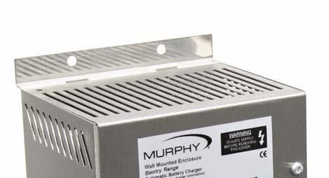
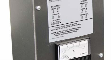
8 General Product Information Please read the following information before installing. A visual inspection of this product for damage during shipping is recommended before installation. It is your responsibility to ensure that qualified mechanical and electrical technicians install this product. The Sentry battery charger provides automatic, current limited and voltage controlled charging of vented lead acid batteries. They may be used in a wide range of industrial charging applications, including standby engines, pumps and generators. The charger is supplied in an open frame construction, designed for surface mounting in an enclosed panel with charging indication via an ammeter and voltmeter. Each unit consists of a transformer, rectifier and thyristor control circuit. The control circuit ensures that the charger maintains a battery voltage at the pre-calibrated float level, while supplying any additional load current up to the specified maximum. Auto Boost (Equalizing) Operation Auto boost operation provides an increased output voltage when batteries are below a preset point. Once the batteries have reached the boost voltage the charger reverts to its float voltage. This operation equalizes the batteries, maximizing battery life and capacity. Boost Initiate Operation The boost initiate switch forces the charger to enter an auto boost cycle even if battery voltage is above the preset point. Once this operation is completed the charger returns to it s float voltage. Temperature Compensation The remote temperature compensation provides control of the output voltage based upon temperature. As temperature increases the charging voltage is decreased at a negative coefficient of 3mV/ F/Cell. Charge Fail A self diagnosis charge fail circuit and relay output is provided. The volt-free relay deenergizes in the event of a charging fault. Electrical connection of the AC and DC supply and alarms are via spring-clamp terminals
9 Current Limiting The Sentry battery charger is current limited and will only output a rated 5A of current. Battery Charged Condition When charged, the battery will only accept a charge to replace the losses within the battery (approximately 1mA per AH of battery). If there is a standing load (the control panel, etc.) the charger will output the standing load plus the losses to the battery. If a standing load of 1A is present with 50AH Vented Lead Acid batteries, then the charger will supply 1.05 amps. A charged battery with open circuit terminals (no load connected) will always be higher than nominal battery voltage (12.6 on a 12V lead acid battery). Dimensions W D H Weight lbs. (140mm) (115mm) (281mm) (5.6Kg)
10 Installation and Mounting Instructions Mounting hole dimensions: Width (between holes) 2.6 (66mm) Height (between holes) (255mm) Mounting holes 0.2 (6mm) Wall Mounted Enclosure The charger must be mounted as shown in the figure above. The lower face is removed by unscrewing the two screws. The face is removed by sliding the face backward, thereby releasing the feet from their fixing holes. Conduit entry is via knock-outs on either side of the unit. These must be carefully removed from the enclosure sides. A suitable cable-gland (0.8 /20mm DIA) should be used to prevent damage to cables and stop unwanted entry into inner part of charger. See Terminal Connection Information section of the chapter on Operating Instructions for details of terminal connections. The lower face should be firmly screwed to the charger before use. Four sets of nuts, bolts, flat and lock washers should be used to mount the unit. Ensure bolts are tightened firmly. Adequate consideration should be given to ventilation for proper heat dissipation. The minimum clearances for proper venting are 12 inches on top, and 6 inches for bottom and sides. CAUTION: When handling chargers, care should be taken not to place excessive strain on the protective aluminum back plate, PCB, transformer or connecting wires. Unit should be handled by the steel enclosure

11 Operating Instructions Before operating the battery charger, ensure that the charger is assembled and installed according to the installation instructions. WARNING: DANGER OF INJURY OR DEATH Before connection, disconnection or handling of Sentry battery charger, ensure that all AC power supplies are disconnected. NOTE: Connection to or disconnection from live wiring can also cause damage to internal components. Terminal Connection Information Output: Input: Charge Fail: To battery CAUTION: Observe correct polarity AC supply CAUTION: Observe correct voltage as stated on unit. Com Common N/O Normally open N/C Normally closed Stripped wire is introduced just before the clamping unit. The clamp spring is pressed down and wire is introduced into the clamping unit immediately. The clamp spring is released the conductor is automatically clamped. NOTE: All connections, including AC input and DC output are made via springclamp connections as outlined above. The Sentry charger is fitted with a self-resetting polyfuse on the dc output. If reverse polarity or short circuit faults occur, remove AC power, disconnect the output(s) and allow poly-fuse to reset. The charger can then be re-connected and switched back on. No replacement of output fuse should be necessary. If fuse fails to reset, the charger should be returned to supplier
12 Automatic Battery Charger The Sentry charger range is an automatic battery charger. If battery voltage falls below a preset voltage (10.2V on a 12V lead-acid battery) the charger will automatically enter an increased charging voltage state (boost). Once the batteries have reached a charged state, the charger will switch to its normal float voltage. This prevents over-charge, which in turn prevents the battery from over-gassing and subsequently maximizes battery life. Charger Connectivity WARNING! The Sentry charger is not user serviceable. No attempt should be made to replace or repair the charger. Any attempt to do so may invalidate any warranties and could cause serious personal harm or injury as well as damage to both the battery charger and any connected devices. In the event of failure the charger should be returned to the suppler. Connection to Utility Supply Ensure AC power supply is off before connecting to the battery charger. Ensure that the unit is properly grounded at the grounding stud located to the left of the AC/DC terminal block on the chargers chassis. CAUTION: Ensure correct AC voltage is supplied to unit. Applying 240VAC on a 120VAC unit will destroy it and could cause serious personal injury
13 Connection to Batteries Ensure AC supply is off before connecting charger to batteries. Ensure battery type and voltage are correct before connecting to batteries. WARNING: Charging either different voltage or type of batteries from stated type may result in damage to both the charging unit and/or batteries and could result in serious personal injury. Disconnection of Batteries Ensure AC supply is isolated before disconnecting charger from batteries. WARNING: Disconnecting the batteries while the power supply is connected to the charger could result in a spark at battery terminals, which could ignite the hydrogen given off from the batteries. Boost Initiate Connection The charger will be in its normal mode of operation while the boost link is broken. Upon connecting the two boost initiate terminals the charger will perform a single auto-boost cycle. While the charger outputs a higher voltage, once the battery voltage has reached this point, the charger returns to its normal float mode of operation. Charge Fail Connection In a de-energized state the COM N/C contact is alarmed. The relay energizes on power up and changes state to COM N/O. These dry contacts are rated at 30VDC. Fuses The wall mounted enclosure is fitted with internal AC input fuses at the stated ratings. Before replacing any fuses, ensure AC power to the charger is off
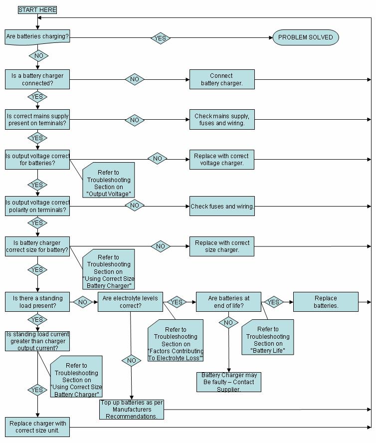
14 Troubleshooting
. 2.")
15 Measuring Charging Voltage and Current To verify that the charger is working, follow these steps then consult the expected conditions listed below. 1. VOLTAGE Place voltmeter across battery terminals ( V in diagram). 2. CURRENT Break the positive line to the battery and place an ammeter between positive from charger and positive of battery ( A in diagram). CAUTION: Only connect an ammeter in series with the power to the charger disconnected. Be very careful about connections to the battery, as it is live, and can short if considerable care is not taken. Current Flow from Charger to Battery If voltage at terminals is less than nominal battery voltage then the maximum rated charger current should be present. NOTE: Once battery is fully charged, output current should be between 0.1% and 0.5% of batteries AH capacity plus any standing loads. Voltage Rise at Battery Terminals A gradual rise of voltage should be seen showing as float voltage is reached batteries should not be boost charged continuously. NOTE: If the battery voltage increases rapidly during charge and no minimum current is measured then the battery may have become sulphated and will not hold charge and may be unrecoverable. Output Voltage 12/v 24/v LEAD Float: 13.6V 27.2V ACID Boost: 14.1V 28.2V Typical output with no battery or load connected. The pre-calibrated float voltage should be present
16 Using Correct Size Battery Charger The battery charger will need to provide both the standing load and minimum charge current. If a charging current of 2A is required, and the standing load is 1A, then the charger needs to be able to output a total of 3 amps. Refer to genset manual for sizing of battery chargers to generator set. If installing your own chargers, lead acid battery manufacturers recommend the following: Minimum charge current should be approximately 5% battery AH capacity. Maximum charge current to be equal to 25% battery AH capacity NOTE: When batteries are normally charged by a charging alternator, a float battery charger rated at lower than the minimum charge current is sufficient to keep batteries in fully charged state. Factors Contributing to Electrolyte Loss Physical damage to cells can cause electrolyte to leak or evaporate. High charging voltages will evaporate electrolyte. Check charging voltage against battery type and voltage. Battery Life WARNING: If the batteries are being used at above 68 Fahrenheit, the chargers output voltage will be temperature compensated at - 3mV/ F/Cell. Two possible methods can be used for determining battery life: Using Hydrometer Using a digital DC voltmeter Follow these steps to check battery life. 1. Fully charge the batteries. 2. Disconnect batteries and leads and leave for 24 hours. 3. Measure either specific gravity (hydrometer) or terminal voltage (voltmeter) and compare with the table on the following page
17 % Charge Specific Gravity Voltage (DC) on a 12V battery Discharged NOTE: If the voltage across the terminals shows around 10.5V, this may indicate a shorted cell is present. 4. If time is limited due to on-site testing, remove surface charge by either applying a 20a load for 3 minutes or crank engine for 10 seconds, then disconnect batteries and leads and leave for minimum of 10 minutes. NOTE: On this method, providing batteries have been sized correctly for engine and charged correctly, an open terminal voltage of 12.5V or greater should be present. WARNING! Adjusting the potentiometers on the PCB may be cause for voiding warranty. They are factory set for the application stated on the label and are not meant to be adjusted by the user under any circumstances
18 Specifications Power Supply Nominal operating voltages 120V Units Permissible voltage variation - ± 6% of nominal Nominal operating frequency 50/60Hz DC Charge Output Maximum current ADC 5 Nominal voltage VDC 12 Float/boost voltages These are factory preset for specified batteries, typical settings are as follows: Vented lead acid Float voltage 13.6V Vented lead acid Boost voltage 14.1V Charge Fail Output Relay type volt free SPDT dry contacts relay de-energized on fault. Contact rating 30VDC (resistive load) General Transformer Single phase Hz Class 130 Operating temperature C to +131 C (-10 C to +55 C) Wall mounted enclosure models Dimensions 11.1 (281mm)(H) x 5.5 (140mm)(W) x 4.6 (115mm)(D); weight 11.9 lbs / 5.6Kg EMC emission/immunity EN / EN
19 MURPHY and the Murphy logo are registered and/or common law trademarks of Murphy Industries, Inc. This document, including textual matter and illustrations, is copyright protected by Murphy Industries, Inc., with all rights reserved. (c) 2007 Murphy Industries, Inc. Other third party product or trade names referenced herein are the property of their respective owners and are used for identification purposes only

20
Guardian Battery Charger Series. Installation and Operations Manual Section 75
 Guardian Battery Charger Series Installation and Operations Manual 00-02-0615 02-29-08 Section 75 In order to consistently bring you the highest quality, full featured products, we reserve the right to
MODEL 6010A 6 12 VOLT BATTERY CHARGER ASSOCIATE
 MODEL 600A 6 VOLT BATTERY CHARGER ASSOCIATE IMPORTANT SAFETY INSTRUCTIONS. SAVE THESE INSTRUCTIONS. This manual contains important safety and operating instructions for the battery charger you have purchased.
12V 1 AMP (1000 ma) Automatic Battery Charger & Maintainer
 Automatic Battery Charger & Maintainer") 12V 1 AMP (1000 ma) Automatic Battery Charger & Maintainer For lead-acid batteries THIS MANUAL CONTAINS IMPORTANT SAFETY AND OPERATING INSTRUCTIONS FOR 12V BATTERY CHARGER: YUA1201000 / INT1201000 KEEP
12V 1 AMP (1000 ma) Automatic Battery Charger & Maintainer For lead-acid batteries THIS MANUAL CONTAINS IMPORTANT SAFETY AND OPERATING INSTRUCTIONS FOR 12V BATTERY CHARGER: YUA1201000 / INT1201000 KEEP
OPERATOR'S MANUAL IMPORTANT SAFETY INSTRUCTIONS
 ASSOCIATED OPERATOR'S MANUAL IMPORTANT SAFETY INSTRUCTIONS MODEL 6366 12 VOLT, 0-20 AMP 4 X 20 BATTERY CHARGER 1. SAVE THESE INSTRUCTIONS. This manual contains important safety and operating instructions
BATTERY CHARGER CHR-1445
 BATTERY CHARGER CHR-1445 / 2685 TEL:886-4-2238-0698 FAX:886-4-2238-0891 Web Site:http://www.monicon.com.tw E-mail:sales@monicon.com.tw Copyright 2007 Monicon Instruments Co., Ltd. All right reserved. Contents
AUTO CHARGE 11 MODEL #: XX. AUTOMATIC BATTERY CHARGER U.L. Configuration INSTRUCTION MANUAL
 INSTRUCTION MANUAL AUTO CHARGE 11 AUTOMATIC BATTERY CHARGER U.L. Configuration MODEL #: 091-11-XX NOTE : This charger is designed for vehicles with dual batteries and negative ground. CAUTION This unit
LESTRONIC II BATTERY CHARGER MODEL 07210
 LESTRONIC II BATTERY CHARGER MODEL 07210 PLEASE SAVE THESE IMPORTANT SAFETY AND OPERATING INSTRUCTIONS For correct operation of the equipment, it is important to read and be familiar with this entire manual
MODEL 6017 OPERATOR'S MANUAL
 MODEL 6017 OPERATOR'S MANUAL ASSOCIATE D IMPORTANT SAFETY INSTRUCTIONS 1. SAVE THESE INSTRUCTIONS. This manual contains important safety and operating instructions for the battery charger you have purchased.
AUTO CHARGE 12 AUTOMATIC BATTERY CHARGER
 INSTRUCTION MANUAL FILE: 091-165-12 reve Rev: E, page 8 DATE: 7-02-15 AUTO CHARGE 12 AUTOMATIC BATTERY CHARGER MODEL #091-165-12 NOTE : This charger is designed for vehicles with a single battery and negative
Sentinel 150 series Automatic switch mode battery chargers Installation, Operation and Maintenance
 yi6503 2016-04-29 Sentinel 150 series Automatic switch mode battery chargers Installation, Operation and Maintenance Open frame models Enclosed models This Manual Refers to the Following Models Standard
SP6. Automatic Battery Charger. Model
 Model SP6 Automatic Battery Charger OWNERS MANUAL PLEASE SAVE THIS OWNERS MANUAL AND READ BEFORE EACH USE. This manual will explain how to use the charger safely and effectively. Please read and follow
IMPORTANT SAFETY INSTRUCTIONS
 1163714 1.5 AMP 12VOLT TRICKLE 1.5 AUTOMATIC AMP AUTOMATIC TRICKLE 1.5 AMP AUTOMATIC 12V12VOLT BATTERY CHARGER IMPORTANT SAFETY INSTRUCTIONS 1. SAVE THESE INSTRUCTIONS This product offers a wide range
Models: SP3, SPSS3 Automatic Battery Charger
 OWNERS MANUAL Models: SP3, SPSS3 Automatic Battery Charger PLEASE SAVE THIS OWNERS MANUAL AND READ BEFORE EACH USE. This manual will explain how to use the charger safely and effectively. Please read and
801 BUSINESS CENTER DRIVE MOUNT PROSPECT, ILLINOIS Ext. 322
 277-999 ELECTRIC CORP. 801 BUSINESS CENTER DRIVE MOUNT PROSPECT, ILLINOIS 800-621-5485 Ext. 322 Send Warranty Product Repairs to: 605 South Vermilion, Suite C, Brownsville, TX 78521-6851 Call Customer
OWNER S MANUAL. Model YUA2AMPCH 2 AMP Dual-Bank Automatic Battery Charger & Maintainer READ ENTIRE MANUAL BEFORE USING THIS PRODUCT
 Model YUA2AMPCH 2 AMP Dual-Bank Automatic Battery Charger & Maintainer Certified by California BCS Regulations OWNER S MANUAL READ ENTIRE MANUAL BEFORE USING THIS PRODUCT READ ENTIRE MANUAL BEFORE USING
801 BUSINESS CENTER DRIVE MOUNT PROSPECT, ILLINOIS
 280-600 Send Warranty Product Repairs to: 1025 E. Thompson Ave., Hoopeston, IL 60942-0280. Call Customer Service if you have questions: 1-800-621-5485 A. IMPORTANT SAFETY INSTRUCTIONS 1. SAVE THESE INSTRUCTIONS
MODEL A97 SERIES. Switchmode Utility Rectifier/Battery Charger ECN/DATE
 MODEL A97 SERIES Switchmode Utility Rectifier/Battery Charger CPN108172 ISSUE DATE: 16071 7/03 ECN/DATE 106 BRADROCK DRIVE DES PLAINES, IL. 60018-1967 (847) 299-1188 FAX: (847)299-3061 Page 1 of 7 INSTRUCTION
MODEL A96 SERIES. 130Vdc Switchmode Utility Rectifier / Battery Charger. Used with LaMarche Power Cage ECN/DATE
 MODEL A96 SERIES 130Vdc Switchmode Utility Rectifier / Battery Charger Used with LaMarche Power Cage CPN112138 ECN/DATE ISSUE DATE: ECN 17010-12/05 106 BRADROCK DRIVE DES PLAINES, IL. 60018-1967 (847)
10AMP FULLY AUTOMATIC 6V & 12V BATTERY CHARGER OWNER'S MANUAL
 1244502 10AMP FULLY AUTOMATIC 6V & 12V BATTERY CHARGER OWNER'S MANUAL 1. IMPORTANT SAFETY INSTRUCTIONS 1.1 SAVE THESE INSTRUCTIONS This manual contains important safety and operating instructions. 1.2
CRS1, CRS2 and CRS3. For additional information please call our. PRO CHARGING SYSTEMS, LLC 1551 Heil Quaker Boulevard, LaVergne, TN
 CRS1, CRS2 and CRS3 For additional information please call our Technical Support Group 800.742.2740 PRO CHARGING SYSTEMS, LLC 1551 Heil Quaker Boulevard, LaVergne, TN 37086-3539 110310 Installation and
2/10/50 AMP 12 VOLT BATTERY CHARGER/ ENGINE STARTER
 2/10/50 AMP 12 VOLT BATTERY CHARGER/ ENGINE STARTER WARNING This product contains or, when used, produces a chemical known to the State of California to cause cancer and birth defects or other reproductive
AUTO CHARGE 12 HO MODEL #: MODEL #: MODEL #: AUTOMATIC SINGLE OUTPUT BATTERY CHARGER INSTRUCTION MANUAL
 INSTRUCTION MANUAL AUTO CHARGE 12 HO AUTOMATIC SINGLE OUTPUT BATTERY CHARGER MODEL #: 091-170-6 MODEL #: 091-170-12 MODEL #: 091-170-24 File: IM_091-170-xx_revd.indd Rev: D Revised By: MFG Date: 10-23-2013
INSTRUCTION MANUAL. 12-Station HD Shop 12V Portable Battery Charger
 INSTRUCTION MANUAL 12-Station HD Shop 12V Portable Battery Charger IMPORTANT SAFETY INSTRUCTIONS 1. SAVE THESE INSTRUCTIONS This manual contains important safety and operating instructions for your HD
Safety, Installation And Operating Instructions For The Following Battery Charger Models: i2412, i3612, i4809, i2425, i3625, and i4818
 Safety, Installation And Operating Instructions For The Following Battery Charger Models: i2412, i3612, i4809, i2425, i3625, and i4818 IMPORTANT NOTICE: Please save and read these safety, operating and
IMPORTANT SAFETY INSTRUCTIONS IMPORTANT: READ AND SAVE THIS SAFETY AND INSTRUCTION MANUAL. KEEP IT WITH OR NEAR CHARGER AT ALL TIMES.
 IMPORTANT SAFETY INSTRUCTIONS IMPORTANT: READ AND SAVE THIS SAFETY AND INSTRUCTION MANUAL. KEEP IT WITH OR NEAR CHARGER AT ALL TIMES. SPECIFICATIONS: For technical assistance, call your Dealer with the
AC CONVERTER / BATTERY CHARGER
 AC CONVERTER / BATTERY CHARGER User s Manual MODEL #: CON120AC12/24VDC Listed to UL 458 and CSA 22.2 NO. 107.1 Standards Contents INTRODUCTION... 3 Important Safety Instructions... 3 1. General Description...
A48 / A48B (base plate) BATTERY CHARGER
 BATTERY CHARGER") A48 / A48B (base plate) BATTERY CHARGER CPN41054 ISSUE DATE: 12315-8/98 ECN/DATE 106 BRADROCK DRIVE DES PLAINES, IL. 60018-1967 (847) 299-1188 FAX: (847)299-3061 15349-07-07/02 16041 6/03 14575-2/01 INSTRUCTION
A48 / A48B (base plate) BATTERY CHARGER CPN41054 ISSUE DATE: 12315-8/98 ECN/DATE 106 BRADROCK DRIVE DES PLAINES, IL. 60018-1967 (847) 299-1188 FAX: (847)299-3061 15349-07-07/02 16041 6/03 14575-2/01 INSTRUCTION
AUTO CHARGE DUAL MODEL #: AUTOMATIC DUAL OUTPUT BATTERY CHARGER INSTRUCTION MANUAL. Ph: Fax:
 INSTRUCTION MANUAL AUTO CHARGE DUAL AUTOMATIC DUAL OUTPUT BATTERY CHARGER MODEL #: 091-145-12 INPUT: 120 Volt, 50/60 Hz, 3.5 Amps OUTPUT BAT 1: 10 Amps OUTPUT BAT 2: 10 Amps File: IM_091-145-12_revb.indd
LESTRONIC II BATTERY CHARGER MODEL 19740
 *01679* LESTRONIC II BATTERY CHARGER MODEL 19740 PLEASE SAVE THESE IMPORTANT SAFETY AND OPERATING INSTRUCTIONS For correct operation of the equipment, it is important to read and be familiar with this
10 AMP ON BOARD BATTERY CHARGER
 R A Valley Forge Company MODEL 2611A-1-B 10 AMP ON BOARD BATTERY CHARGER One Output OWNER S MANUAL IMPORTANT! READ THESE INSTRUCTIONS BEFORE INSTALLING AND USING THIS PRODUCT. Keep these instructions for
Model: OBD-L On-Board-Diagnostics II Memory Saver Detector
 Model: OBD-L On-Board-Diagnostics II Memory Saver Detector OWNERS MANUAL IMPORTANT SAFETY INSTRUCTIONS SAVE THESE INSTRUCTIONS This manual will show you how to use your memory saver detector safely and
LESTRONIC II BATTERY CHARGER BUILT-IN OR PORTABLE CHARGERS
 LESTRONIC II BATTERY CHARGER BUILT-IN OR PORTABLE CHARGERS PLEASE SAVE THESE IMPORTANT SAFETY AND OPERATING INSTRUCTIONS For correct operation of the equipment, it is important to read and be familiar
AUTO CHARGE 4000 MODEL #: LOW PROFILE CHARGER AUTOMATIC DUAL OUTPUT BATTERY CHARGER INSTRUCTION MANUAL
 INSTRUCTION MANUAL AUTO CHARGE 4000 LOW PROFILE CHARGER AUTOMATIC DUAL OUTPUT BATTERY CHARGER Unit supplied with this display MODEL #: 091-89-12 INPUT: 120 Volt, 50/60 Hz, 5 Amps OUTPUT: 45 Amps File:
INTELLIGENT BATTERY CHARGER/MAINTAINER
 INTELLIGENT BATTERY CHARGER/MAINTAINER OWNER S MANUAL Read carefully and understand all ASSEMBLY AND OPERATION INSTRUCTIONS before operating. Failure to follow the safety rules and other basic safety precautions
BatteryMINDer 1500* & BatteryMINDer Plus 1510*
 BatteryMINDer 1500* & BatteryMINDer Plus 1510* both with SmarTECHnology 12 Volt 1500 ma Charger - Maintainer - Desulfator INCLUDES: Auto-Temp Compensation Sensor, installed (1500 & 1510) Optional Permanent
Operating Instructions
 Operating Instructions PRO- If you sell, inventory or service lead-acid batteries, you want the battery you take off the shelf to be as new as the day it was manufactured. However, batteries that sit idle
AUTO CHARGE D2 MODEL #: AUTOMATIC TRIPLE OUTPUT BATTERY CHARGER INSTRUCTION MANUAL
 INSTRUCTION MANUAL AUTO CHARGE D2 AUTOMATIC TRIPLE OUTPUT BATTERY CHARGER Designed Specifically for Vehicles with DDEC ENGINES MODEL #: 091-74-12 INPUT: 120 Volt, 60 Hz, 8 Amps OUTPUT VEHICLE BATTERY 1
PUMP PLUS 2000 PLC MODEL #: PP AUTOMATIC DUAL OUTPUT BATTERY CHARGER INSTRUCTION MANUAL
 INSTRUCTION MANUAL PUMP PLUS 2000 PLC AUTOMATIC DUAL OUTPUT BATTERY CHARGER Supplied with Dual Bar Graph Display MODEL #: 091-237-12-PP INPUT: 120 Volt, 60 Hz, 3.5 Amps OUTPUT BATTERY 1 and 2: 15 or 18
AUTO CHARGE D PUMP PLUS
 INSTRUCTION MANUAL AUTO CHARGE D PUMP PLUS AUTOMATIC DUAL OUTPUT BATTERY CHARGER Designed Specifically for Vehicles with DDEC ENGINES MODEL #: 091-9-DPP INPUT: 120 Volt, 60 Hz, 8 Amps OUTPUT VEHICLE BATTERY:
BATTERY SAVER LOW RIPPLE HO
 INSTRUCTION MANUAL BATTERY SAVER LOW RIPPLE HO LOW RIPPLE POWER SUPPLY / AUTOMATIC LOAD SWITCH FOR 12VDC VEHICLE SYSTEMS MODEL #: 091-195-12 INPUT: 120 Volt, 50/60 Hz, 4.5 Amps RMS OUTPUT: 13.2 Volts DC,
24 VOLT AUTOMATIC BATTERY CHARGER PART NO
 24 VOLT AUTOMATIC BATTERY CHARGER PART NO. 957732 AC Input: DC Output: Battery Type: Specifications 230 volts, 50 hertz, 3.5 amps, single-phase 24 volts, 20 amps initially tapering to 6 amps 24 volt, 12
12 Volt 1500 ma Convertible Charger - Maintainer - Desulfator*
 1215C 12 Volt 1500 ma Convertible Charger - Maintainer - Desulfator* INCLUDES: Auto-Temp Compensation Sensor, installed Optional Permanent Mounting Brackets and screws Battery Clips (Fully-Insulated 6
AUTO CHARGE 4000 MODEL #: AUTOMATIC DUAL OUTPUT BATTERY CHARGER INSTRUCTION MANUAL. Ph: Fax:
 INSTRUCTION MANUAL AUTO CHARGE 4000 AUTOMATIC DUAL OUTPUT BATTERY CHARGER MODEL #: 091-89-12 INPUT: 120 Volt, 50/60 Hz, 8 Amps OUTPUT BATTERY CHARGER: 40 Amps OUTPUT BATTERY SAVER: 5 Amps File: IM_091-89-12_reve.indd
LPC 20 MODEL #: LOW PROFILE CHARGER AUTOMATIC SINGLE OUTPUT BATTERY CHARGER INSTRUCTION MANUAL
 INSTRUCTION MANUAL LPC 20 LOW PROFILE CHARGER AUTOMATIC SINGLE OUTPUT BATTERY CHARGER Unit supplied with one of these displays MODEL #: 091-207-12 INPUT: 120 Volt, 50/60 Hz, 7 Amps OUTPUT: 20 Amps File:
Cruising Charger Series OWNER S MANUAL
 R Cruising Charger Series OWNER S MANUAL ON BOARD BATTERY CHARGERS Models DC Amperage No. Of Banks Volts 2614A 5,10 Amps 2 Bank 12/12 2614A-230 2621A 5,5,10 Amps 3 Banks 12/12/12 2621A-230 2622A 10,10
2603 Battery Pal 3 AMP, 1 2 VOLT BATTERY CHARGER
 R 2603 Battery Pal 3 AMP, 1 2 VOLT BATTERY CHARGER Connections at a glance: The GUEST Battery Pal 2603 is designed to recharge your battery, and extend your battery s life in applications where it is stored
Model: SE-4020-CA Automatic Battery Charger
 OWNERS MANUAL Model: SE-4020-CA Automatic Battery Charger PLEASE SAVE THIS OWNERS MANUAL AND READ BEFORE EACH USE. This manual will explain how to use the battery charger safely and effectively. Please
MODEL 2602A-12 3 STAGE AUTOMATIC BATTERY CHARGER OWNER S MANUAL SAVE THESE INSTRUCTIONS
 R A Valley Forge Company MODEL 2602A-12 3 STAGE AUTOMATIC BATTERY CHARGER OWNER S MANUAL SAVE THESE INSTRUCTIONS 1. INTRODUCING THE CHARGER The 2602A-12 is a 3-stage electronic battery charger. Rainproof,
30,000mWh LITHIUM-POLYMER CAR JUMP STARTER USER S MANUAL PLEASE READ THIS MANUAL CAREFULLY BEFORE OPERATION
 Lithium Battery Disposal: This product contains a lithium battery. A lithium battery should not be thrown away in the trash. Please dispose of the battery at an authorized disposal or recycle center. Check
Installation and Operating Instructions (for chargers shown below)
") Installation and Operating Instructions (for chargers shown below) For additional information please call our Technical Support Group 800.742.2740 PRO CHARGING SYSTEMS, LLC 1551 Heil Quaker Boulevard,
Installation and Operating Instructions (for chargers shown below) For additional information please call our Technical Support Group 800.742.2740 PRO CHARGING SYSTEMS, LLC 1551 Heil Quaker Boulevard,
Deltran Battery Tender 6V/12V 4Amp 5 & 10 Bank Battery Management System TABLE 1. Length of Cord, Feet AWG Size of Cord
 Deltran Battery Tender 6V/12V 4Amp 5 & 10 Bank Battery Management System Designed for Six-cell and three-cell Flooded/AGM/GEL Lead-Acid Batteries and Four-Cell Lithium Iron Phosphate (LiFePO4) Batteries
PUMP PLUS 1000 PLC MODEL #: PP AUTOMATIC SINGLE OUTPUT BATTERY CHARGER INSTRUCTION MANUAL
 INSTRUCTION MANUAL PUMP PLUS 1000 PLC AUTOMATIC SINGLE OUTPUT BATTERY CHARGER Unit supplied with one of these displays MODEL #: 091-215-12-PP INPUT: 120 Volt, 60 Hz, 3.5 Amps OUTPUT BATTERY 1 and 2: 15
DieHard. BATTERY CHARGER/MAINTAINER 1.5 Amp Fully Automatic Float-Mode Monitoring. Model No
 OWNER'S MANUAL DieHard. BATTERY CHARGER/MAINTAINER 1.5 Amp Fully Automatic Float-Mode Monitoring Model No. 200.71220 CAUTION: Read and follow all Safety Rules and Operating Instructions Before Every Use
FULLY AUTOMATIC SCR BATTERY CHARGER
 *35589* FULLY AUTOMATIC SCR BATTERY CHARGER FEATURES Microprocessor controlled charge circuit monitors battery state of charge and automatically turns charger off when the batteries reach full charge.
ACCUSENSE CHARGE SERIES ON/OFF BOARD FULLY AUTOMATIC BATTERY CHARGER
 ACCUSENSE CHARGE SERIES ON/OFF BOARD FULLY AUTOMATIC BATTERY CHARGER SPECIFICATIONS: *Photo for reference only* Part number 8890439 Mode Select: Selects Battery Type Refer to Section 6. IMPORTANT: READ
AUTOMATIC BEST BATTERY SELECTOR INSTALLATION & OPERATION BBS-4800 BBS-4800E
 AUTOMATIC BEST BATTERY SELECTOR INSTALLATION & OPERATION BBS-4800 BBS-4800E SENS part no: 101312 Document revision: K DCN No. 107455 Date 4/2/18 1840 Industrial Circle Longmont, CO 80501 Fax: (303) 678-7504
12V Manual Battery Charger
 OPERATOR S MANUAL 12V Manual Battery Charger Model No. 28.71221 Read and follow all Safety Rules and Operating Instructions before Every Use of this Product. SAVE THESE INSTRUCTIONS. Sears Brands Management
Battery. Charger Model: Save Important Safety Instructions
 Owner's Manual Battery Charger Model: SS-51A-PE, 10 Amp Fully Automatic Battery Charger For 12 Volt Marine Deep Cycle & Automotive Batteries Save Important Safety Instructions Read Rules for Safe Operation
MB V 3-IN-1 JUMP STARTER WITH SPIRAL WOUND BATTERY
 MB3730 12V 3-IN-1 JUMP STARTER WITH SPIRAL WOUND BATTERY 1 IMPORTANT SAFETY INSTRUCTIONS 1. SAVE THESE INSTRUCTIONS - This manual contains important safety and operating instructions for this PowerStation.
AUTOMATIC BEST BATTERY SELECTOR INSTALLATION & OPERATION BBS-1600 BBS-1600E
 AUTOMATIC BEST BATTERY SELECTOR INSTALLATION & OPERATION BBS-1600 BBS-1600E SENS part no: 101314 Document revision: H DCN No. 107395 Date 11/22/17 1840 Industrial Circle Longmont, CO 80501 Fax: (303) 678-7504
LPC 40 MODEL #: LOW PROFILE CHARGER WITH PLC AUTOMATIC SINGLE OUTPUT BATTERY CHARGER INSTRUCTION MANUAL
 INSTRUCTION MANUAL LPC 40 LOW PROFILE CHARGER WITH PLC AUTOMATIC SINGLE OUTPUT BATTERY CHARGER Unit supplied with one of these displays MODEL #: 091-200-12 INPUT: 120 Volt, 50/60 Hz, 5 Amps OUTPUT: 40
ELECTRONIC MARINE CONVERTER/CHARGER Owners Manual Models PD2020, PD2030, PD2040, PD2050, PD2060, PD2080
 Table Of Contents ELECTRONIC MARINE CONVERTER/CHARGER Owners Manual Models PD2020, PD2030, PD2040, PD2050, PD2060, PD2080 Thank you for purchasing the INTELI-POWER MARINE converter/charger. The INTELI-POWER
SNTL150P1205CD SNTL150P2405CD SNTL150P1205CDA SNTL150P2405CDA
 yi6504 revision A, 2017-02-24 Sentinel 150P series Programmable, automatic switch mode battery chargers Installation, Operation and Maintenance This Manual Refers to the Following Models Open frame models
SAVE THESE INSTRUCTIONS
 R MODEL 2611 10 AMP ON BOARD BATTERY CHARGER Two Outputs OWNER S MANUAL Connections at a glance: For the best charging results both 12 Volt independent batteries should be equally discharged. The charger
36 VOLT AUTOMATIC BATTERY CHARGER PART NO
 36 VOLT AUTOMATIC BATTERY CHARGER PART NO. 957727 AC Supply: DC Output: Battery Type: Specifications 120 volts, 60 Hertz, 10 amps, single-phase 36 volts, 20 amps initially tapering to 6 amps 36 volt, 18
installation and operating instructions for the following xtreme Battery chargers:
 installation and operating instructions for the following xtreme Battery chargers: Model Name No. of Banks Amps Per Bank Battery System Dual Pro SE Xtreme Dual Pro Xtreme Three Bank SE Xtreme Three Bank
BATTERY CHARGER OWNER S MANUAL POWER CHARGER Part # volt Amp
 BATTERY CHARGER OWNER S MANUAL POWER CHARGER Part # 74016 12-16 volt Amp ----CAUTION---- READ THIS MANUAL CAREFULLY FOR RULES OF SAFE OPERATION AND PROPER USE OF THIS CHARGER ***SAVE THESE INSTRUCTIONS***
A39 UNIVERSAL SCR CHARGER
 A39 UNIVERSAL SCR CHARGER ECN/DATE CPN35971 21681 01/18 16816-6/05 15349-03 05/02 14575 02/01 14268 10/00 10400 9/96 106 BRADROCK DRIVE DES PLAINES, IL. 60018-1967 (847) 299-1188 FAX: (847) 299-3061 ISSUE
24V HEAVY DUTY JUMP STARTER/ POWER BANK MB3752. Storage. Specifications
 Storage Warning! When not in use store your instruction manual and product in a safe and dry place. Before re-use after storage it is recommended that the product is checked by a suitably qualified person
12V/25A BATTERY CHARGER MAINTAINER / JUMPSTARTER
 12V/25A BATTERY CHARGER MAINTAINER / JUMPSTARTER OWNER S MANUAL Read carefully and understand all ASSEMBLY AND OPERATION INSTRUCTIONS before operating. Failure to follow the safety rules and other basic
LESTRONIC II AUTOMATIC BATTERY CHARGER MODEL TYPE 36LC21-6ET
 LESTRONIC II AUTOMATIC BATTERY CHARGER MODEL 18590 TYPE 36LC21-6ET Input: Output: Charge Rate: Specifications 100 or 200 VAC, 60 Hertz, single-phase 36 VDC, 21 Amps Start rate of 21 amps at 2.11 volts/cell
PSJ-2212, PSJ-3612, PSJ-4424
 Model: PSJ-2212, PSJ-3612, PSJ-4424 Jump Starter and DC Power Source OWNER S MANUAL PSJ-2212 PLEASE SAVE THIS OWNER S MANUAL AND READ BEFORE EACH USE. This manual will explain how to use your jump starter
OPERATOR S MANUAL JUMP STARTER. and DC Power Source. Model No CAUTION: Sears, Roebuck and Co., Hoffman Estates, IL U.S.A.
 OPERATOR S MANUAL JUMP STARTER and DC Power Source Model No. 71489 CAUTION: Read and follow all Safety Rules and Operating Instructions before Every Use of this Product. SAVE THESE INSTRUCTIONS. Sears,
FC/FCA 12, 24, 32 & 48 VOLT, 6 & 10 AMP BATTERY CHARGER OPERATION & MAINTENANCE GUIDE
 FC/FCA 12, 24, 32 & 48 VOLT, 6 & 10 AMP BATTERY CHARGER OPERATION & MAINTENANCE GUIDE SENS part number: 101037 Document revision: A Engineering change number: 105073 Date: 1/13/2006 1840 Industrial Circle
February EN-B POWER CHARGE PSC-700. Power Supply / Maintenance Charger for 12-volt Batteries/Systems INSTRUCTION MANUAL
 February 2017 167-000182EN-B POWER CHARGE PSC-700 Power Supply / Maintenance Charger for 12-volt Batteries/Systems INSTRUCTION MANUAL Blank page Contents General Safety Precautions 4 Personal Precautions
24 VOLT DUAL MODE WHEELCHAIR BATTERY CHARGER MODEL TYPE 24EL8 E&J PRODUCT NO
 24 VOLT DUAL MODE WHEELCHAIR BATTERY CHARGER MODEL 12630 TYPE 24EL8 E&J PRODUCT NO. 90483465 Specifications AC Supply: 120 volts, 60 Hertz, single-phase, 4 amps maximum DC Output: 24 volts, 8 amps, tapering
POWER TO GET THE JOB DONE
 52722 10 AMP 12 VOLT BATTERY CHARGER OWNER S MANUAL OVERCHARGING PROTECTION 10 Amp, 12 Volt Fully automatic and manually selectable Includes overcharging protection in automatic mode Reverse hook-up protection
IMPORTANT SAFETY INSTRUCTIONS
 ASSOCIATED Model 6039 Battery Tester Operator's Manual IMPORTANT SAFETY INSTRUCTIONS 1. SAVE THESE INSTRUCTIONS This manual contains important safety and operating instructions for the battery tester you
MASTERsine Inverter PXA Series Installation Guide
 Backup Power System Expert TM MASTERsine Inverter PXA Series Installation Guide Important Safety Instructions IMPORTANT: Read and save this Installation Guide for future reference. This chapter contains
LC BATTERY CHARGER OPERATION & MAINTENANCE GUIDE
 LC BATTERY CHARGER OPERATION & MAINTENANCE GUIDE SENS part number: 101194 Document revision: D DCN number: 105128 Date: 3/23/2006 1840 Industrial Circle Longmont, CO 80501 Fax: 303-678-7504 Tel: 303-678-7500
VAc A. Rc Ah. Table of contents. OpERATION MAINTENANcE. Safety... 2 Specifications... 6 Operation Maintenance Warranty...
 Table of contents Safety... 2 Specifications... 6 Operation... 7 Maintenance... 10 Warranty... 12 SAFETy SpEcIFIcATIONS OpERATION MAINTENANcE VAc A cca Rc Ah WARNING SyMBOLS AND DEFINITIONS This is the
PI1500X Power Inverter User s Manual
 PI1500X Power Inverter User s Manual featuring WARNING Failure to follow instructions may cause damage or explosion, always shield eyes. Read entire instruction manual before use. Warning: This product
Installation and Operating Instructions (for chargers shown below)
") Installation and Operating Instructions (for chargers shown below) For additional information please call our Technical Support Group 800.742.2740 PRO CHARGING SYSTEMS, LLC 1551 Heil Quaker Boulevard,
Installation and Operating Instructions (for chargers shown below) For additional information please call our Technical Support Group 800.742.2740 PRO CHARGING SYSTEMS, LLC 1551 Heil Quaker Boulevard,
12 VOLT 30 AMP DIGITAL SOLAR CHARGE CONTROLLER
 12 VOLT 30 AMP DIGITAL SOLAR CHARGE CONTROLLER User s Manual Congratulations on your Coleman solar product purchase. This product is designed to the highest technical specifications and standards. It will
INSTRUCTION MANUAL FOR PC63 CAGE
 INSTRUCTION MANUAL FOR PC63 CAGE CPN106833 ISSUE DATE: 15689-12/02 ECN/DATE 106 BRADROCK DRIVE DES PLAINES, IL. 60018 (847) 299-1188 FAX: (847) 299-3061 16816-6/05 INSTRUCTION DRAWING NUMBER: P25-LPC63-1
General Precautions. Personnel Precautions
 USER MANUAL General Precautions 1. Before using Inverex, read all instructions and cautionary markings on : (1) Inverex (2) the batteries (3) this manual 2. CAUTION --To reduce risk of injury, charge only
EASY CHARGE Waterproof portable Battery Charger
 EASY CHARGE Waterproof portable Battery Charger 1.1 AND 4.3 AMP MODELS EN NL, DE, FR, ES, IT USER S MANUAL WWW.MASTERVOLT.COM/EASYCHARGE-PORTABLE 10000009117/04 2 EN / EasyCharge 1.1 and 4.3 Amp - User
EASY CHARGE Weather-resistant fixed mount Battery Charger
 EASY CHARGE Weather-resistant fixed mount Battery Charger 6 AMP AND 10 AMP MODELS EN NL, DE, FR, ES, IT USER S MANUAL WWW.MASTERVOLT.COM/EASYCHARGE 10000009118/01 2 EN / EasyCharge 6 and 10 Amp - User
Go Power! Manual. GP-Smart Charger
 Go Power! Manual GP-Smart Charger Go Power! Electric Inc. PO Box 6033 Victoria, BC V8P 5L4 Toll Free Tel: 866-247-6527 Toll Free Fax: 866-607-6527 Email: info@gpelectric.com Table of Contents 1. IMPORTANT
PureSine 150/300 Pure Sine Wave Inverter User s Manual
 PureSine 150/300 Pure Sine Wave Inverter User s Manual 1. Important Safety Instructions WARNING! Before you install and use your Inverter, please read and follow these safety instructions. 1-1. General
44,400mWh LITHIUM-POLYMER CAR JUMP STARTER USER S MANUAL PLEASE READ THIS MANUAL CAREFULLY BEFORE OPERATION
 ENX12K Lithium Battery Disposal: This product contains a lithium battery. A lithium battery should not be thrown away in the trash. Please dispose of the battery at an authorized disposal or recycle center.
OPERATOR S MANUAL. Portable Power 950. Model No
 OPERATOR S MANUAL Portable Power 950 Model No. 28.71987 Read and follow all Safety Rules and Operating Instructions before Every Use of this Product. Save these instructions. Sears Brands Management Corporation,
7 Stage Automatic Smart Battery Charger (FOR CHARGING 12V / 24V AGM, GEL,SLA AND WET BATTERIES) USER MANUAL
 USER MANUAL") 7 Stage Automatic Smart Battery Charger Desulphuration& Maintainer (FOR CHARGING 12V / 24V AGM, GEL,SLA AND WET BATTERIES) USER MANUAL THIS MANUAL CONTAINS IMPORTANT SAFETY AND OPERATING INSTRUCTIONS 1
7 Stage Automatic Smart Battery Charger Desulphuration& Maintainer (FOR CHARGING 12V / 24V AGM, GEL,SLA AND WET BATTERIES) USER MANUAL THIS MANUAL CONTAINS IMPORTANT SAFETY AND OPERATING INSTRUCTIONS 1
BC12M248 7 Stage Automatic Smart Battery Charger, Desulfator & Maintainer 12V, 2 / 4 / 8A FOR AGM, GEL AND WET BATTERIES USER MANUAL
 BC12M248 7 Stage Automatic Smart Battery Charger, Desulfator & Maintainer 12V, 2 / 4 / 8A FOR AGM, GEL AND WET BATTERIES USER MANUAL THIS MANUAL CONTAINS IMPORTANT SAFETY AND OPERATING INSTRUCTIONS 1 IMPORTANT
MODEL ELC-12/40-CVM-D BATTERY CHARGER
 NATIONAL RAILWAY SUPPLY MODEL ELC-12/40-CVM-D BATTERY CHARGER Installing, Operating and Service Instructions for the ELC-12/40-CVM-D Solid State Charger PLEASE SAVE THESE IMPORTANT SAFETY AND OPERATING
Owner s Manual & Safety Instructions
 Owner s Manual & Safety Instructions Save This Manual Keep this manual for the safety warnings and precautions, assembly, operating, inspection, maintenance and cleaning procedures. Write the product s
Automatic Battery Charger Switching mode with Micro-controlled Input: Vac / Output: 12Volt DC
 Automatic Battery Charger Switching mode with Micro-controlled Input:100-140Vac / Output: 12Volt DC User s Manual and Important Safety Information Model: #20085 (SW121080-06) FEATURES Congratulations on
PUMP PLUS 1200 MODEL #: AUTOMATIC SINGLE OUTPUT BATTERY CHARGER INSTRUCTION MANUAL
 INSTRUCTION MANUAL UM LUS 1200 AUTOMATIC SINGLE OUTUT BATTERY CHARGER Unit supplied with one of these displays MODEL #: 091-193-12 INUT: 120 Volt, 60 Hz, 10 Amps OUTUT: 40 Amps File: IM_091-193-12_revH.indd
Automatic Battery Charger Switching mode with Micro-controlled Input: Vac / Output: 12Volt DC
 Automatic Battery Charger Switching mode with Micro-controlled Input:220-260Vac / Output: 12Volt DC User s Manual and Important Safety Information Model: OC-SW121080 / OC-SW121160 / OC-SW121210 FEATURES
Art. No. EC-315. Art. No. EC-330. Art. No. EC-340 SWITCH-MODE BATTTERY CHARGER CONTENTS IMPORTANT SAFETY PRECAUTIONS... 2
 SWITCH-MODE BATTTERY CHARGER CONTENTS IMPORTANT SAFETY PRECAUTIONS... 2 DESCRIPTION AND FEATURES... 3 CHARGING STAGES... 4 Art. No. EC-315 Art. No. EC-330 Art. No. EC-340 PROTECTIONS... 5 INSTALLATION...