Sunica.plus Technical manual
|
|
|
- Vanessa Reed
- 5 years ago
- Views:
Transcription


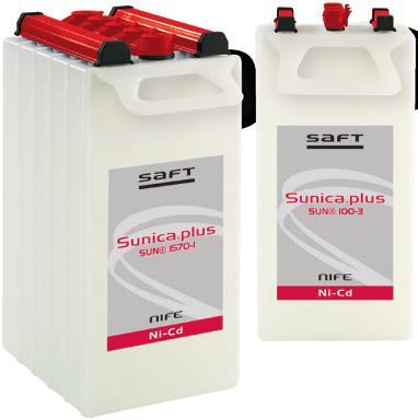
1 Sunica.plus Technical manual
2 Contents 1. Introduction 4 2. The photovoltaic application 4 3. Sunica.plus construction 3.1. Plate assembly Separator Electrolyte Terminal pillars Venting system Cell container 6 4. Sunica.plus benefits 7 5. Operating features 5.1. Capacity Cell voltage Internal resistance Effect of temperature on performance Short circuit values Open circuit loss Cycling Effect of temperature on lifetime Water consumption Battery charging 6.1. Charging generalities Charge efficiency Temperature effects Regulators Special operating factors 7.1. Electrical abuse Ripple effects Over-discharge Overcharge Mechanical abuse Shock loads Vibration resistance External corrosion Battery sizing principles 8.1 Introduction The basic principles Battery sizing example Installation and operating instructions 9.1. Receiving the shipment Storage Installation Location Ventilation Mounting Electrolyte Commissioning Cells stored up to 6 months Cells stored more than 6 months and up to 2 years Cell electrolyte after prolonged float charge Charging in service Maintenance Disposal and recycling 22 3
3 1. Introduction The nickel-cadmium battery is the most reliable battery system available in the market today. Its unique features enable it to be used in applications and environments untenable for other widely available battery systems. It is not surprising, therefore, that with the photovoltaic (PV) market and its rigorous requirements, the nickel-cadmium battery has become an obvious first choice for users looking for a reliable, low maintenance, system. This publication details the design and operating characteristics of the Saft Nife brand Sunica.plus battery to enable a successful photovoltaic system. Sunica.plus is built upon solid Saft expertise with more than 20 years field experience. The Sunica.plus is one of the most reliable batteries under the sun. In application, the Sunica.plus operates worry free for years with only occasional and infrequent water topping and performs extended cycling in uncontrolled environments and at partial state of charge. 2. The photovoltaic application The typical requirements for photovoltaic (PV) applications are ruggedness, environmental flexibility, unattended operation, ease of installation, and reliability. Photovoltaic applications include: Navigational Aids: offshore, remote lighthouses, beacons Telecommunications: emergency telephone posts, radio repeater stations, base stations Rail Transport: crossing guards lighting, signalling, isolated telephone stations Oil and Gas: cathodic protection for pipelines, emergency lighting on offshore platforms Utilities: electrification in remote areas A photovoltaic system is made up of three distinct parts: The photovoltaic array which is built to give up to 20 years of service life Electronic components such as blocking diodes and logic circuits, power conditioners, controllers and voltage regulators The battery must provide worry free available autonomy, all the time. Systems are often installed in remote areas, at sites accessible only by foot, helicopter or boat, in good weather conditions and with only limited skilled labour available. Thus, the ideal photovoltaic power system is a reliable installation which requires only infrequent maintenance calls where the battery plays a crucial part. The characteristics of the battery must not result in a failure of the system. For photovoltaic applications, the most important characteristics required in a battery are: ability to withstand cycling, daily and seasonally ability to withstand high and low environmental temperatures ability to operate reliably, unattended and with minimal maintenance ruggedness for transportation to remote sites easily installed with limited handling equipment and unskilled labour reliability and availability during the 20 years service life of the photovoltaic modules resistance to withstand failure of electronic control systems no need for refreshing charges high charge efficiency during periods of low insolation (typically cold winter seasons) REGULATOR Sunica + Solar panels = ~ DC load AC load 4


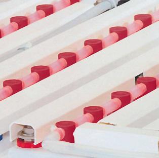
4 3. Sunica.plus construction Protective cover Prevents external short-circuits. The covers are in line with EN and IEC (safety) with IP2 level. Flame arresting vent Handles Moulded polypropylene handles allow Sunica.plus batteries to be easily manoeuvred and installed. Plate group bus Connects the plate tabs with the terminal post. Plate tabs and terminal posts are projection welded to the plate group bus. Plate tab Spot welded to the plate side frames, to the upper edge of the pocket plate and to the plate group bus. Separators These separate the plates and insulate the plate frames from each other. This special type of separator improves the internal recombination. Cell container Made of tough polypropylene. Plate Horizontal pockets of double-perforated steel strips. Plate frame Seals the plate pockets and serves as a current collector. Automated integral water filling system Saft s automated integral water filling system is available as an option for the Sunica.plus range. The construction of the Saft Nife brand Sunica.plus cell is based upon the proven Saft pocket plate technology. Special features are included to enhance its use in the specialised photovoltaic application. 5
5 3.1 Plate assembly The nickel-cadmium cell consists of two groups of plates, one containing nickel hydroxide (the positive plate) and the other containing cadmium hydroxide (the negative plate). The active materials of the Saft Sunica.plus pocket plate have been specially developed and formulated to improve its cycling ability, a specific need for photovoltaic applications. These active materials are retained in pockets formed from nickel plated steel which is double perforated by a patented process. The pockets are mechanically linked together, cut to the size corresponding to the plate length and compressed to the final plate dimension. This process leads to a component which is not only mechanically very strong but also retains its active material within a steel boundary which promotes conductivity and minimises electrode swelling. These plates are welded to a current carrying bus bar assembly which further ensures the mechanical and electrical stability of the product. Nickel-cadmium batteries have an exceptionally good cycle life because their plates are not gradually weakened by repeated cycling since the structural component of the plate is steel. The active material of the plate is not structural, only electrical. The alkaline electrolyte does not react with steel, which means that the supporting structure of the Sunica.plus battery stays intact and unchanged for the life of the battery. There is no corrosion and no risk of sudden death. 3.2 Separator The separator is a key feature of the Sunica.plus battery. It is a polypropylene fibrous material which has been used and proven by Saft in the Ultima ultra-low maintenance product over more than 20 years. It has been further optimized for this product to give the features required. Using this separator, the distance between the plates is carefully controlled to give the necessary gas retention for an optimum level of recombination. By providing a large spacing between the positive and negative plates and a generous quantity of electrolyte between plates, the possibility of thermal runaway is eliminated. 3.3 Electrolyte The electrolyte used in Sunica.plus is a solution of potassium hydroxide and lithium hydroxide. It is optimised to give the best combination of performance, life, cycling ability and energy efficiency while operating in a wide operational temperature range. The concentration allows the cell to operate in extremely low and high temperatures, i.e., - 20 C (- 4 F) to + 50 C (+ 122 F). For temperatures below - 20 C (- 4 F) a special high density electrolyte can be used to improve its charge and discharge performance. An important consideration of Sunica.plus, and indeed all nickel-cadmium batteries, is that the electrolyte does not change during charge and discharge. It retains its ability to transfer ions between the cell plates irrespective of the charge level. In most applications the electrolyte will retain its effectiveness for the life of the battery and will never need replacing. 3.4 Terminal pillars Terminal pillars are welded to the plate bus bars using a well-proven block battery construction. They are constructed of nickel-plated steel and are internally threaded. The pillar to lid seal uses a compressed visco-elastic sealing method. The pillars are held in place by compression lock washers. This assembly is designed to provide satisfactory sealing throughout the life of the product. 3.5 Venting system Sunica.plus is fitted with a flame arresting flip-top vent to simplify topping-up and is supplied with a transportation plug to ensure safe transportation. There is also an option of a water filling system which has been proven by Saft in railway applications over many years. This gives semi-automatic filling and an effective and safe gas venting system. 3.6 Cell container Sunica.plus is built using the well-proven block battery construction. The tough polypropylene containers are welded together by heat sealing and the assembly of the blocks are completed by a clip-on terminal cover which gives protection to IP2 X according to IEC standard for the conductive parts. 6
6 4. Sunica.plus benefits Complete reliability The Sunica.plus does not suffer from the sudden death failure associated with other battery technologies. Long cycle life Sunica.plus has a long cycle life and delivers up to cycles at 15 % depth of discharge during a twenty year life (see section 5.7 Cycling). Exceptional long life Sunica.plus incorporates all the design features associated with the conventional Saft twenty year life products to ensure that, in many applications, it can achieve or exceed this lifetime compared to available battery technologies. Low maintenance With its special recombination separator and generous electrolyte reserve, Sunica.plus reduces the need for topping-up with water. It can be left in remote sites for long periods and will, depending upon application demands, give up to 6 years without the need for topping-up. Charge efficiency Good charge efficiency at normal temperatures and excellent charge efficiency at low temperatures ensure that the battery is charged during the winter period. Wide operating temperature range Sunica.plus has a special optimised electrolyte which allows it to have a normal operating temperature of from - 20 C to + 50 C (- 4 F to F), and accept extreme temperatures, ranging from as low as - 50 C to up to + 70 C (- 58 F to up to F). Resistance to mechanical abuse Sunica.plus is designed with a high mechanical strength. It withstands all the harsh treatment associated with transportation over difficult terrain (see section 7.2 Mechanical abuse). High resistance to electrical abuse While the use of a voltage regulator is recommended to obtain maximum overall efficiency of the system, the failure of this component will not damage the battery. It will simply cause an overcharging of the battery and so use extra water. The Sunica.plus battery is resistant to overcharge and over-discharge conditions compared to the other battery technologies (see section 7.1 Electrical abuse). Well-proven pocket plate construction Saft has nearly 100 years of manufacturing and application experience with respect to the nickel-cadmium pocket plate product and this expertise has been built into the twenty plus years design life of the Sunica.plus product (see section 3 Sunica.plus construction) Low installation costs Sunica.plus can be used with a wide range of photovoltaic systems as it produces no corrosive vapours, uses corrosion-free polypropylene containers and has a simple bolted assembly system. Extended storage When stored in the filled and charged state in normal condition (0 C to + 30 C / + 32 F to + 86 F), Sunica.plus can be stored for up to 2 years (see section 9 Installation and operating instructions). Environmentally safe Saft operates a dedicated recycling center to recover the nickel, cadmium, steel and plastic used in the battery (see section 11 Disposal and recycling). 7
7 5. Operating features 5.1. Capacity The Sunica.plus battery capacity is rated in ampere hours (Ah) at the C 120 discharge rate. It is the quantity of electricity supplied for a 120 hour discharge period to a cut-off voltage of 1.0 volt per cell after being fully charged. This nominal value of capacity is regarded as the most useful for sizing photovoltaic applications Cell voltage The cell voltage of Sunica.plus like all nickel-cadmium cells results from the electrochemical potentials of the nickel and the cadmium active materials in the presence of the potassium hydroxide electrolyte. The nominal voltage for this electrochemical couple is 1.2 volts Internal resistance The internal resistance of a cell varies with the type of service and the state of charge. It is difficult to define and measure accurately. In the fully charged state and at high temperature, the internal resistance is the lowest. The internal resistance is characterized by measuring the response in discharge voltage with a change in discharge current. The internal resistance of a Sunica.plus cell has the values given in the product literature for fully charged cells at normal temperature. For lower states of charge the values increase. At 50 % discharged, the internal resistance is about 20 % higher, and at 90 % discharged, it is about 80 % higher. When the temperature decreases below 20 C, the internal resistance increases. At 0 C (+ 32 F), the internal resistance is about 40 % higher. Table 1 shows typical values for a 100 Ah cell (values in mω). Table 1 - Internal resistance for a 100 Ah cell (in mω) for different conditions Temperature Fully charged 50 % discharged 90 % discharged + 20 C (+ 68 F) C (+ 32 F) Effect of temperature on performance Variations in ambient temperature affect the performance of Sunica.plus and this must be accounted for when sizing the Sunica.plus battery for a minimum expected autonomy. Low temperature operation reduces the discharge performance and at high temperature, the discharge performance is only slightly affected. The effect of temperature impacts the performance more significantly at higher rates of discharge. The temperature de-rating factors used for sizing a Sunica.plus battery are given for cells with standard electrolyte in Figure 1. At temperatures below + 20ºC (+ 68 F), the ability to discharge is impacted by the ability to deliver charged capacity with an increased resistance. At temperatures above + 20ºC (+ 68 F), the ability to charge is impacted by a reduced efficiency. When the special high density electrolyte is used, for operating temperatures below - 20ºC (- 4ºF) use the temperature de-rating factors given in Figure 2. 8
8 Figure 1. Temperature de-rating: standard electrolyte for operating temperatures from - 20 C to + 40 C (- 4 F to F) 1.0 De-rating factor End voltage 1.14 V End voltage 1.16 V End voltage 1.18 V End voltage 1.20 V 0.7 De-rating factors to apply on RT performance according to temperature and end voltage ºC - 20ºC - 10ºC 0ºC + 10ºC + 20ºC + 30ºC + 40ºC - 22ºF - 4ºF + 14ºF + 32ºF + 50ºF + 68ºF + 86ºF + 104ºF Temperature Figure 2. Temperature de-rating: special electrolyte for operating temperatures down to - 40 C (- 40 F) De-rating factor De-rating factors to apply on RT performance according to temperature and discharge rate; end voltage 1.14 V 0-50ºC - 45ºC - 40ºC - 35ºC - 30ºC - 25ºC - 20ºC - 15ºC - 10ºC - 5ºC 0ºC - 58ºF - 49ºF - 40ºF - 31ºF - 22ºF - 13ºF - 4ºF + 5ºF + 14ºF + 23ºF + 32ºF Temperature C A 0.01 C A C A 0.02 C A 0.03 C A 5.5. Short circuit values The typical short circuit value in amperes for a Sunica.plus cell is approximately 6 times the C 120 capacity, e.g. for a 100 Ah cell the short circuit value would be 600 amperes. The Sunica.plus battery is designed to withstand a short circuit current of this magnitude for many minutes without damage Open circuit loss The state of charge of the Sunica.plus cell on open circuit stand slowly decreases with time due to self-discharge. At + 20 C (+ 68 F), this decrease is relatively rapid during the first two weeks but then stabilises to about 2 % per month. The self-discharge is affected by the temperature. At low temperatures, the charge retention is better and the open circuit loss is reduced. At high temperature the self-discharge is increased and the open circuit loss is also increased. The open circuit loss for Sunica.plus is shown in Figure 3. For up to 2 years of storage time, storing Sunica.plus in a high state of charge is required. 9
9 Figure 3. Typical open circuit loss variation with time 110 % of initial capacity C ºC (+ 104ºF) + 20ºC (+ 68ºF) 0ºC (+ 32ºF) Open circuit period (days) 5.7. Cycling Sunica.plus is designed to withstand the daily cycling encountered in photovoltaic applications. It can operate at a partial state of charge without detriment. The available cycling life depends on the Depth Of Discharge (DOD) each day. A shallow cycle (say 15 %) will give more than cycles, whereas a deep cycle (say 80 %) will give about 1000 cycles. The available cycling life also depends on the operating temperature of the Sunica.plus. At higher temperatures, the number of expected cycles will decrease. Figure 4 shows the number of expected cycles as a function of Depth Of Discharge (DOD) and operating temperature. The number of cycles given are after a 30 % capacity loss where 70 % of the beginning of life capacity is still available for use. In practice, in photovoltaic applications, the battery is exposed to a large number of relatively shallow cycles. The cycles are normally operated at different states of charge due to the variation of sun insolation each day. In order to simulate this, the IEC Standard specifies an accelerated cycling test. The procedure replicates a photovoltaic energy system operating in very severe conditions. It consists of a period of operation with a high state of charge, to simulate the effect of overcharge on the lifetime of the battery, and a period of operation with a low state of charge, to simulate the effect of a poor state of charge on a battery. The cycling is done at + 40 C (+ 104 F). With this extreme scenario, the test results should demonstrate the survivability of a battery when used in a worst case photovoltaic operating regime. Figure 4. Typical cycle life values at different temperatures ºC (+ 104ºF) + 20ºC (+ 68ºF) 0ºC (+ 32ºF) Number of cycles Life time criteria: Capacity = 70 % of rated capacity Depth of discharge (% C 5 Ah)
10 Figure 5. Sunica.plus cycling to IEC Standard % of the initial battery capacity Battery capacity evolution when cycled as per IEC Number of cycles The Sunica.plus delivered 1800 cycles according to IEC (see Figure 5). The test results demonstrate its superior cycling ability after being subjected to continuous cycling at a partial state of charge (low and high) and at a fixed + 40 C (+ 104 F) Effect of temperature on lifetime Sunica.plus is designed as a twenty year life product but, as with every battery system, increasing temperature reduces the expected life. However, the reduction in lifetime with increasing temperature is much lower for the Sunica.plus when compared to the lead acid battery. As referenced in IEEE 1106 standard, the general rule of thumb when considering the aging characteristic of nickel-cadmium is that is will lose approximately 1% of its capacity per year at temperatures less than or equal + 25 C (+ 77 F). The available calendar life as a function of temperature of Sunica.plus is compared with a lead acid battery in Figure 6. In sizing calculations, it is common to predict the lifetime of the Sunica.plus to be the same at + 25 C to + 30 C (+ 77 F to + 86 F). This is normal since the actual observed lifetimes in the field often exceed the general rule of thumb. Figure 6. Available calendar life as a function of temperature % of + 25ºC (+ 77ºF) lifetime Nickel-cadmium Lead acid ºC + 30ºC + 35ºC + 40ºC + 45ºC + 50ºC + 55ºC + 77ºF + 86ºF + 95ºF + 104ºF + 113ºF + 122ºF + 131ºF Temperature In general terms for every + 10 C (+ 18 F) increase above + 25 C (+ 77 F), the calendar life of the Sunica.plus is reduced by 20 %. The lead acid battery is reduced by 50 % in the same case. 11
11 5.9. Water consumption Water in the electrolyte is consumed when the Sunica.plus is overcharged. It is necessary to overcharge each cycle to maintain a high state of charge since the charge efficiency is less than unity. This overcharge, breaks down the water of the electrolyte into oxygen and hydrogen gas. Gas that is not recombined will exhaust from the cell. As a result, distilled water has to be added periodically. Water loss is associated with the current used for overcharging. A battery which is constantly cycled i.e. is charged and discharged daily, will consume more water than a battery on standby operation. A recombination separator is used in the Sunica.plus and it reduces the water usage considerably by enhancing the internal recombination of gas. The consumption of water varies according to the voltage, temperature and the level of cycling. Table 2 summarizes the minimum expected watering interval of the Sunica.plus. Table 2 - Typical watering interval of Sunica.plus Charge voltage 1.5 V 1.55 V 1.6 V Daily DOD 5 % to 10 % 10 % to 15 % 15 % to 25 % Topping-up interval at + 20 C (+ 68 F) 6 years 4 years 2 years Topping-up interval at + 40 C (+ 104 F) 3 years 2 years 1 year 6. Battery charging 6.1. Charging generalities The photovoltaic array converts solar irradiance into dc electrical power. Unlike a mains connected system, the output from a photovoltaic array is variable. To obtain the best efficiency from the system, it is normal for the photovoltaic array to include some form of charge control. When the solar panels are sized in such a way that they can provide the needed energy to the load during the season of low solar radiation, the Sunica.plus will operate at a partial state of charge. In the high solar radiation season, the extra energy is then available for recovering full battery capacity. In practice, the charge voltage is the main parameter which can be used to optimise the state of charge of the Sunica.plus for a given solar application. The optimised charge voltage is linked to the daily Depth Of Discharge (DOD) which depends on the sized autonomy. The optimized charge voltage is set to maintain a high state of charge cycle after cycle with low water consumption The daily Depth Of Discharge (DOD) In order to define the optimised charge voltage, it is necessary to define the daily DOD. This daily DOD is determined from the fact that the Sunica.plus is charging during the day and is discharging during the night. For example, with a Sunica.plus sized to deliver between 2 to 5 days of autonomy, the daily DOD will range from 5 to 20 % DOD. The following example illustrates a typical daily DOD. The Sunica.plus was sized for 5 days of autonomy with a load of 50 W. It follows that the needed energy is, 5 x 24 x 50 W = 6000 Wh The energy discharged during the night is 50 W for about 12 h. So, each day the Sunica.plus has to supply 50 W x 12 h = 600 Wh. From this the daily DOD is 600 Wh / 6000 Wh i.e. 10 %. The daily DOD varies due to the actual hours of discharge required each night. 12
12 6.1.2 Optimum charge voltage The needed charge voltage to maintain a high state of charge depends on the daily DOD. Deeper daily DOD, the higher the charge voltage is needed with a given amount of sun insolation each day. The charge voltage values are optimized in order to keep the high state of charge at the same level regardless of the daily DOD. Figure 7 illustrates the recommended charge voltage as a function of daily DOD. Figure 7. Charge voltage required for high state of charge Charge voltage per cell (V) Minimum voltage level 1.35 Recommended charge voltage according to the daily DOD and at + 20ºC (+ 68ºF) Daily DOD in % When cycling with this recommended charge voltage, the Sunica.plus will stabilize at greater than 95 % state of charge. The solar panels should be sized to provide a minimum needed energy to maintain this high state of charge. Values for the minimum needed charge energy is provided in the Saft sizing outputs Charge efficiency The charge efficiency of Sunica.plus is dependent on the state of charge of the battery and the temperature. At states of charge lower than 80 % and temperatures between + 10 C to + 25 C (+ 50 F to + 77 F), it is recharged at a high level of efficiency. When cycling at + 20 C (+ 68 F), at the recommended value of charge voltage, the Ah efficiency is close to 100 % at a 50 % state of charge. The efficiency is better than 90 % at 95 % state of charge. At higher temperatures the Ah efficiency is reduced. At + 40 C (+ 104 F), the charge efficiency ranges between 96 % to 82 % between 50 % and 95 % state of charge. When the charge voltage is less than or more than the recommended value, the stabilised state of charge and the charge efficiency will vary up or down accordingly. The relationship between the charge efficiency and the daily Depth Of Discharge (DOD), autonomy and charge voltage for + 20 C (+ 68 F) is shown in Table 3. Table 3 - Typical Ah efficiencies under different application conditions Daily DOD Typical autonomy Charge voltage per cell Expected SOC Ah efficiency at H SOC Ah efficiency at 50 % SOC 5 to 10 % 5 days or V 95 % >90 % 100 % 10 to 15 % 3 to 5 days 1.55 V 95 % >90 % 100 % 15 to 25 % 2 to 5 days 1.6 V 95 % >90 % 100 % It is important to note that the charging efficiency of Sunica.plus is not reduced with time and so this does not have to be taken into account in battery sizing. In practice, a photovoltaic system s battery normally has a state of charge between 20 % and 80 % and in this case the charging efficiency of Sunica.plus remains high. 13
13 6.3. Temperature effects As the temperature increases, the electrochemical behaviour becomes more active and so, for the same charge voltage, the current at the end of charge increases. This current increase compensates for the variation in charge efficiency at high temperatures. For this reason, it is not recommended to use temperature compensation of the charge voltage at ambient temperatures above 0 C (+ 32 F). In terms of water loss, this is not increased significantly at these higher temperatures due to the effectiveness of the partial gas recombination features of Sunica.plus. As the ambient temperature is reduced, then the reverse occurs. In that case, when the ambient temperature falls below 0 C (+ 32 F), using temperature compensation of the charge voltage is recommended. This is particularly useful to maintain a high state of charge in the critical period of the year. The temperature compensated charge voltage should be equivalent to mv per C and per cell ( mv per F per cell) when the ambient falls below 0 C (+ 32 F). 6.4 Regulators A pulse width modulator (PWM) type regulator For a PWM type regulator the advised charge voltage should be based on the daily Depth Of Discharge (DOD) according to the values in Table 4. Table 4 - PWM regulator recommended charge voltages for different conditions Voltage system 12 V 24 V 48 V Typical number of Ni-Cd cells Daily DOD Typical autonomy Charge voltage per cell 5 to 10 % 5 days or V 10 to 15 % 3 to 4 days 1.55 V 15 to 25 % 2 to 3 days 1.6 V A battery regulator based on the switching principle For this type of regulator it is useful to define the boost threshold (not mandatory), the float threshold and the charge reconnect threshold. Typical threshold values for a battery system with Sunica.plus defined for 5 days or more autonomy is shown in Table 5. Table 5 - Typical threshold values for switching type regulator Voltage system 12 V 24 V 48 V Typical number of Ni-Cd cells Boost threshold (not mandatory or 1.65 V per cell) 14.7 V 29.4 V 58.8 V Float threshold (by 1.55 V per cell) 14.1 V 28.2 V 56.4 V Battery reconnect threshold (by 1.45 V per cell) 13 V 26 V 52 V End of discharge threshold (not mandatory or 1 V per cell) 9 V 18 V 36 V Recommendation for choosing the voltage regulators The charge voltages shall be adjustable due to the wide charge voltage range of Sunica.plus. The low voltage disconnect shall be adjustable or inhibit due to the deep discharge possible of the Sunica. plus. Regulators with voltage regulation using PWM systems are recommended due to the need of maintaining the charge voltage on the battery during the daily charge process. 14
14 7. Special operating factors 7.1. Electrical abuse Ripple effects The nickel-cadmium battery is tolerant to high ripple and the only effect is that of increased water usage. In general, any commercially available charger or generator can be used for commissioning or maintenance charging of Sunica.plus Over-discharge If more than the designed capacity is taken out of a battery then it becomes over-discharged. This is considered to be an abuse situation for a battery and should be avoided. The Sunica.plus battery can be recovered from an over-discharge without any detrimental effects Overcharge Overcharge is the effect of forcing current through a battery after it is fully charged. For Sunica.plus, with its generous electrolyte reserve, an increase in overcharge will not significantly alter the maintenance period. In the case of excessive overcharge, more frequent water replenishment is required but there will be no significant effect on the life of the battery Mechanical abuse Shock loads The Sunica.plus block battery concept complies with both IEC (bump tests at 5 g, 10 g and 25 g) and IEC (shock test 3 g), where g = acceleration Vibration resistance The Sunica.plus block battery concept was tested to IEC 77 for 2 hours at 1 g and demonstrated compliance External corrosion Sunica.plus nickel-cadmium cells are manufactured in durable polypropylene, all external metal components are nickel plated and these components are protected by a rigid plastic cover. 8. Battery sizing principles 8.1 Introduction The photovoltaic systems type of use and the required reliability are the main factors when sizing the Sunica.plus battery. Professional applications (emergency systems, sea-lights, radio beacons etc.) are generally oversized according to their importance and it is necessary to take into account the working conditions of the system. It is not the purpose of this manual to give sizing methods for complete photovoltaic systems. However, it is useful to discuss the different factors which can affect the design of the system and the battery sizing. The array and battery size are related since the photovoltaic system must have array and battery sizes which are sufficient for the load to operate at all the required times throughout the year. The system could have a small array and a large battery or vice versa. However, there are limits to these sizes as, while the minimum array size is that which can deliver the annual daily load in the average daily insolation, the minimum battery size is that which can supply the overnight load. 15
15 8.2 The basic principles The basic rules controlling the calculation of the correct battery for an application require the calculation of the following parameters: Unadjusted capacity This is the average daily load (in Ah per day) multiplied by the number of days of battery reserve. This capacity has to be adjusted according to the battery characteristics and operating conditions. Discharge adjustment This is the capacity adjusted for life. It is obtained by dividing the unadjusted capacity by the required capacity at the end of life (expressed as a percentage of the rated capacity). Figure 4 shows the number of cycles before reaching a capacity of 70 %. Charge adjustment It is recommended to use a charge voltage optimised for the daily DOD and temperature. With an optimized charge voltage, a high state of charge is optimized with the lowest water consumption. As a guideline, an optimized charge voltage will allow to keep a state of charge at 95 % in its daily cycling. Temperature adjustment Cell capacity ratings are defined at + 20 C to + 25 C (+ 68 F to + 77 F). For temperatures outside this range, it is necessary to use the temperature correction factor (see Figures 1 and 2). Design margin adjustment It is a common practice to provide a design margin to allow for uncertainties in the load. This is usually in the range of 10 to 25 % (or a factor of 0.90 to 0.75). Load current calculation An equivalent load current is calculated. This makes it possible to use the performance table data at + 20 C to + 25 C (+ 68 F to + 77 F). The unadjusted energy can be determined by multiplying the load (watts/amps) by the hours of needed autonomy. This unadjusted energy/capacity can now be adjusted by the necessary adjustment factors to eventually determine the adjusted load to look up in the standard performance tables. The performance tables allow performance lookup based on anticipated end of discharge voltage. 8.3 Battery sizing example In this example, a telecom application is considered. Requirements The average load current = 5 A / 8 days or 192 h of autonomy. There is no information concerning the performance requirement at the battery end of life but we will assume that full autonomy is required. The average temperature is considered to be + 40 C (+ 104 F) and the voltage window: 41.8 V to 54.4 V. The expected load growth which has to be allowed for in the design is 10 %. Unadjusted capacity Calculating a simple unadjusted capacity we have 5 A x 192 = 960 Ah. Discharge adjustment As we anticipate achieving the full 8 days autonomy at the end of life, then, as described in 8.2 above, we will use a factor of 0.7 (70 % of initial capacity). 16
16 Charge adjustment If the charge voltage is in accordance with the recommended value corresponding to the daily Depth Of Discharge (DOD), then the charge adjustment used is Temperature adjustment The temperature adjustment value = 0.95 (Figure 1: + 40 C/+ 104 F) Design margin The design margin adjustment value is 0.9 as allowance for a load growth of 10 % is required. Load current calculation From this data, the calculated battery capacity is 960 Ah / (0.7 x 0.95 x 0.95 x 0.9) = Ah. And the equivalent load current is Ah / 192 h = 8.8 A. End voltage is 41.8 V / 36 cells = 1.16 V. Battery selection in the performance table becomes 8 A / 192 h / 1.16 V = SUN (1 string is required). Charge voltage calculation The daily Depth Of Discharge (DOD) is calculated according to the methodology given in paragraph If we assume that the daily night duration during the critical month is 18 hours, then the daily DOD is 5 A x 18 h x 100/1830 Ah = 4.9 %. Thus the charge voltage to be used is 1.5 V per cell (see the table in paragraph 6.4.1) and the voltage at the battery terminals is 1.5 V x 36 = 54 V which is compatible with the load voltage window. 9. Installation and operating instructions 9.1 Receiving the shipment Do not overturn the package. Check the packages and cells for transport damage. The battery is shipped filled and charged, and is ready for immediate use. Transport seals are located under the lid of each vent; they must be removed prior to mounting. The battery must never be charged with the plastic transport seals in place as this is dangerous and can cause permanent damage Storage Store the battery indoors in a dry, clean, cool location (0 C to + 30 C /+ 32 F to + 86 F) and well-ventilated space on open shelves. Storage of a filled battery at temperatures above + 30 C (+ 86 F) can result in loss of capacity. This can be as much as 5 % per 10 C (18 F) above + 30 C (+ 86 F) per year. Do not store in direct sunlight or expose to excessive heat. Sunica.plus batteries are supplied filled with electrolyte and charged, they can be stored in this condition for a maximum of 24 months from date of shipment. Never drain the electrolyte from the cells. Store without opening the boxes. 17
17 9.3. Installation Location Install the battery in a dry and clean room. Avoid direct sunlight and heat. The battery will give the best performance and maximum service life when the ambient temperature is between + 10 C to + 30 C / + 50 F to + 86 F Ventilation During the last part of charging, the battery is emitting gases (oxygen and hydrogen mixture). At normal float charge, the gas evolution is very small but some ventilation is necessary. Note that special regulations for ventilation may be valid in your area depending on the application Mounting Verify that cells are correctly interconnected with the appropriate polarity. The battery connection to load should be with nickel plated cable lugs. Recommended torques for terminal bolts are: M6=11 ± 1.1 N.m (97.4 ± 9.8 lbf.in) M8=20 ± 2 N.m (177.0 ± 17.7 lbf.in) M10=30 ± 3 N.m (265.0 ± 26.6 lbf.in) The connectors and terminals should be corrosion-protected by coating with a thin layer of anti-corrosion oil. Remove the transport seals and close the vent caps. If a central water filling system is used as an option, refer to the corresponding installation and operating instructions sheet Electrolyte When checking the electrolyte levels, a fluctuation in level between cells is not abnormal and is due to the different amounts of gas held in the separators of each cell. The level should be at least 15 mm above the minimum level mark and there is normally no need to adjust it. Do not top-up prior to initial charge. After commissioning, when the level is stabilized, it should be not less than 5 mm below the maximum level mark Commissioning Verify that the ventilation is adequate during this operation. A good commissioning is important. Charge at constant current is preferable. If the current limit is lower than indicated in Table 6, charge for a proportionally longer time. 18
18 Table 6 Cell type Rated capacity 5 h V C 5 Ah (Ah) Nominal capacity 120 h V C 120 Ah (Ah) Charging current 0.1 C 5 A (A) Max. quantity of water to be added in cc Cell connection bolt per pole SUN M8 SUN M10 SUN M10 SUN M10 SUN M10 SUN xM10 SUN xM10 SUN xM10 SUN xM10 SUN xM10 SUN xM10 SUN xM10 SUN xM10 SUN xM10 SUN xM10 SUN xM10 SUN xM10 SUN xM10 SUN xM10 SUN xM10 SUN xM10 SUN xM10 SUN xM10 SUN xM10 SUN xM10 SUN xM10 SUN xM10 SUN xM10 SUN xM10 SUN xM10 SUN xM10 SUN xM10 SUN xM10 SUN xM10 SUN xM Cells stored up to 6 months: A commissioning charge is normally not required and the cells are ready for immediate use. If full performance is necessary immediately, a commissioning charge as mentioned in section is recommended Cells stored more than 6 months and up to 2 years: A commissioning charge is necessary: Commissioning at ambient temperature between + 10 C to + 30 C (+ 50 F to + 86 F) - Constant current charge: 20 h at 0.1 C 5 A recommended (see Table 6). Note: At the end of charge, the cell voltage will reach about 1.75 V, thus the charger shall be able to supply such a voltage. 19
19 When the charger maximum voltage setting is too low to supply constant current charging, divide the battery into two parts to be charged individually at constant current. - Constant potential charge: 1.55 V/cell for a minimum of 24 h after current limited to 0.1 C 5 A (see the current in Table 6). If these methods are not available, then charging may be carried out at lower voltages, 1.50 V/cell for 36 hours minimum. Commissioning at ambient temperature above + 30 C (+ 86 F) - Only constant current charge: 20 h at 0.1 C 5 recommended. The electrolyte temperature is to be monitored during charge. If the temperature exceeds + 45 C (+ 113 F) during charging, then it must be stopped to reduce the temperature. The charging can be resumed when electrolyte temperature drops below + 40 C (+ 104 F). In the case of remote areas, where the only charger available is the photovoltaic array, the battery should be connected to the system with no connected load and no voltage limit. The battery should then be charged in good sunshine conditions. During this operation, the Ah charged shall be in the magnitude of 1.6 times the rated capacity, and, in order to limit the risk of electrolyte overflow, it is recommended not to exceed the charge current value specified in Table Cell electrolyte after prolonged float charge: Check the electrolyte level and adjust it to the upper level mark by adding distilled or deionized water. Note: When full battery performance is required for capacity test purposes, the battery has to be charged in accordance with IEC section 7 (7.1 & 7.2). 9.5 Charging in service The photovoltaic array converts solar irradiance into DC electrical power at a pre-determined range of voltages whenever sufficient solar radiation is available. Unlike a main connected system, the output from a photovoltaic array is variable and, to obtain the best efficiency from the system, it is quite normal to have some form of charge control. Two main techniques for charging the batteries are generally used in photovoltaic systems. These are those which have a constant voltage limitation based on the PWM technics and those with several voltage steps charging where the battery, by switching means, is charging up to a high pre-set voltage (boost or float threshold), then drops to a lower voltage level (battery reconnect threshold) and then back to the high pre-set voltage and so on. Recommended charging voltages for a typical photovoltaic application sized for 5 days or more back-up time: a) case of constant voltage limitation (PWM regulator system or similar) float: 1.50 V/cell boost (not mandatory): 1.65 V/cell b) case of regulators based on the switching principle: boost threshold (not mandatory): 1.65 V/cell float threshold: 1.55 V/cell battery reconnect threshold: 1.45 V/cell For lower back-up time, the values have to be increased depending of the load requirement. Consult the manufacturer. For use in warm areas, a temperature compensation on the charge voltage is not recommended. For use in cold areas, a temperature compensation is recommended to increase the charge acceptance. The recommended value is: mv/ C/cell ( mv/ F/cell) starting from + 20 C (+ 68 F). 20
20 10. Maintenance In a correctly designed standby application, Sunica.plus requires the minimum of attention. However, it is good practice with any system to carry out an inspection of the system once per year or at the recommended topping-up interval period to ensure that the charging system, the battery and the ancillary electronics are all functioning correctly. When this system service is carried out, it is recommended that the following actions should be taken: Keep the battery clean using only water. Do not use a wire brush or solvents of any kind. Check the charging voltage. In parallel operation, it is of great importance that the recommended charging voltage remains unchanged. The charging voltage should be checked at least once yearly. If a cell float voltage is found below 1.35 V, high rate charge is recommended to apply to the cell concerned. Check visually the electrolyte level. Never let the level fall below the minimum level mark. Use only distilled or de-ionized water to top-up. Topping-up of the Sunica.plus battery shall be carried out when battery is fully charged. Note: There is no need to check the electrolyte density periodically. Interpretation of density measurements is difficult and could be misleading. Check every two years that all connections are tight. The connectors and terminal bolts should be corrosion-protected by coating with a thin layer of anti-corrosion oil. High water consumption is usually caused by improper voltage setting of the charger. 21
21 11. Disposal and recycling In a world where autonomous sources of electric power are ever more in demand, Saft batteries provide an environmentally responsible answer to these needs. Environmental management lies at the core of Saft s business and we take care to control every stage of a battery s life cycle in terms of potential impact. Environmental protection is our top priority, from design and production through end-of-life collection, disposal and recycling. Our respect for the environment is complemented by an equal respect for our customers. We aim to generate confidence in our products, not only from a functional standpoint, but also in terms of the environmental safeguards that are built into their life cycle. The simple and unique nature of the battery components make them readily recyclable and this process safeguards valuable natural resources for future generations. Pure cadmium New batteries Battery use Distillation Spent batteries Cadmium plates Dismantling Ferro nickel Steel works Nickel plates Standards list: Certified IEC Secondary cells and batteries containing alkaline or other non-acid electrolytes - Nickel-cadmium prismatic secondary single cells with partial gas recombination. Sunica.plus exceeds gas recombination requirements. Certified IEC Secondary cells and battery containing alkaline and other non-acid electrolytes - Vented nickel-cadmium prismatic secondary single cells IEC Environmental testing - Part 2: Tests. Test Eb and guidance: Bump IEC Environmental testing - Part 2-77: Tests - Test 77: Body strength and impact shock Complies with EN / IEC Safety requirements for secondary batteries and battery installations - Part 2: Stationary batteries - The protective covers for terminals and connectors, the insulated cables are compliant with IP2 level protection against electrical shocks according to safety standard. Complies with IEC Secondary cells and batteries for renewable energy storage - General requirements and methods of test - Part 1: Photovoltaic, off-grid application. 22


22 Saft is committed to the highest standards of environmental stewardship As part of its environmental commitment, Saft gives priority to recycled raw materials over virgin raw materials, reduces its plants air and water releases year after year, minimizes water usage, reduces fossil energy consumption and associated CO 2 emissions, and ensures that its customers have recycling solutions for their spent batteries. Regarding industrial nickel-based batteries, Saft has had partnerships for many years with collection companies in most EU countries. This collection network receives and dispatches our customers batteries at the end of their lives to fully approved recycling facilities, in compliance with the laws governing trans boundary waste shipments. This collection network meets the requirements of the EU batteries directive. A list of our collection points is available on our web site. In other countries, Saft assists users of its batteries in finding environmentally sound recycling solutions. Please contact your sales representative for further information. Saft Industrial Battery Group 12, rue Sadi Carnot Bagnolet - France Tel. : Fax : Doc No.: Edition: April 2014 Data in this document is subject to change without notice and becomes contractual only after written confirmation. Photo credits: Saft, Fotolia Produced in the UK by Arthur Associates Limited Société par Actions Simplifiée au capital de RCS Bobigny B
Solar Range Technical manual
 P3.1 October 2007 Solar Range Technical manual Solar Range Contents 1. Introduction 3 2. The photovoltaic application 4 3. Construction features of the Alcad Solar battery 5 3.1 Plate assembly 6 3.2 Separation
Uptimax New Generation Ni-Cd battery Technical manual
 Uptimax New Generation Ni-Cd battery Technical manual Contents 1. Introduction 3 2. Applications 3 3. Construction features 3 3.1 Plate assembly 3 3.2 Separator 4 3.3 Electrolyte 4 3.4 Terminal pillars
Uptimax New Generation Ni-Cd battery. Maintenance-free solution for backup power applications
 NiCd battery Maintenancefree solution for backup power applications The ideal choice for total security and availability Saft your trusted battery partner for stationary applications Saft has over years
Uptimax New Generation Ni-Cd battery. Maintenance-free solution for backup power applications
 NiCd battery Maintenancefree solution for backup power applications The ideal choice for total security and availability Saft your trusted battery partner for stationary applications Saft has over years
Uptimax New Generation Ni-Cd battery. Maintenance-free solution for backup power applications
 NiCd battery Maintenancefree solution for backup power applications The ideal choice for total security and availability Saft your trusted battery partner for stationary applications Saft has over 100
V3.4. Vantage. Ultra-low maintenance batteries. Technical manual
 V3.4 Vantage Ultra-low maintenance batteries Technical manual Contents 1 Introduction 3 2 Benefits of the Vantage battery 4 3 Battery applications 5 4 Principles of the oxygen recombination cycle 6 5 Construction
Valve Regulated Pocket Plate Nickel Cadmium Battery. Technical Manual
 Valve Regulated Pocket Plate Nickel Cadmium Battery Technical Manual Contents Pages 1.0. Introduction to VRPP battery 2.0. VRPP - Solution to varied applications 3.0. xygen recombination cycle - A technological
Vantage Ultra-low maintenance batteries
 Ultra-low maintenance batteries V2.6 Ultra-low maintenance batteries Ultra-high reliability, ultra-low maintenance Alcad a powerful combination of proven pocket-plate construction and advanced design from
ULTIMA Ni-Cd BATTERY: PEAK PERFORMANCE WITH ULTRA LOW MAINTENANCE
 ULTIMA Ni-Cd BATTERY: PEAK PERFORMANCE WITH ULTRA LOW MAINTENANCE ULTRA LOW MAINTENANCE Ni-Cd FOR WHEN SAFETY CANNOT BE COMPROMISED Developed in line with long proven nickel-cadmium technology, the Ultima
Single Cell Range Technical manual
 S3.4 April 2007 Single Cell Range Technical manual Contents Single Cell Range 1. Introduction 3 2. Benefits of the Alcad pocket plate Ni-Cd battery 4 2.1 Complete reliability 4 2.2 Long cycle life 4 2.3
Single Cell Range Technical manual
 S3.5 April 2012 Single Cell Range Technical manual Contents Single Cell Range 1. Introduction 3 2. Benefits of the Alcad pocket plate Ni-Cd battery 4 2.1 Complete reliability 4 2.2 Long cycle life 4 2.3
Ni-Cd block battery. Technical manual. August 2018
 Ni-Cd block battery Technical manual August 2018 Contents 1. Introduction 3 2. Benefits of the block battery 4 2.1 Complete reliability 4 2.2 Long cycle life 4 2.3 Exceptionally long lifetime 4 2.4 Low
Saft telecom batteries
 Saft telecom batteries A direct connection to innovation Saft batteries offer the innovation needed for today s telecom applications Meeting a wide range of telecom needs with high performance solutions
Vantage ultra-low maintenance batteries
 Vantage ultra-low maintenance batteries V2. Vantage ultra-low maintenance batteries Ultra-high reliability, ultra-low maintenance Introducing Alcad Vantage a powerful combination of proven pocket-plate
Industrial Standby batteries. A wide offer of reliable, long-life solutions
 Industrial Standby batteries A wide offer of reliable, long-life solutions Saft stationary batteries, solutions you can count on By providing a large choice of technologies and cell configurations as well
Ni-Cd BLOCK BATTERY TECHNICAL MANUAL
 Ni-Cd BLOCK BATTERY TECHNICAL MANUAL Contents 1. Introduction 3 2. Benefits of the block battery 4 2.1 Complete reliability 4 2.2 Long cycle life 4 2.3 Exceptionally long lifetime 4 2.4 Low maintenance
SCL P - SCM Ni-Cd single cells Capacity: 10 Ah to 70 Ah
 SCL P - SCM Ni-Cd single cells Capacity: 10 Ah to 70 Ah Nickel-cadmium single cells are designed for general purpose applications, where maximum operating reliability is a key factor: switch tripping emergency
Nickel Cadmium Batteries BLOCK TYPE
 Nickel Cadmium Batteries BLOCK TYPE POWER BACK-UP WITH NICA NICA your long term partner for power back-up challenges Nica has been a trusted battery for the world s leading industrial players for over
Vented fibre structure Nickel Cadmium batteries for stationary systems
 Vented fibre structure Nickel Cadmium batteries for stationary systems FNC FNC Vented Nickel Cadmium Batteries the best solution for long, reliable battery life FNC Nickel Cadmium single cells are designed
XHP Low maintenance high performance batteries Technical manual
 X3.3 April 2007 XHP Low maintenance high performance batteries Technical manual Contents XHP Range 1. Introduction 3 2. Electrochemistry of Ni-Cd batteries 4 3. Construction features of the XHP battery
NCPP. Nickel Cadmium Pocket Plate Batteries. Block Cell Dimensional and Electrical Data
 NCPP Nickel Cadmium Pocket Plate Batteries Block Cell Dimensional and Electrical Data Nickel Cadmium Pocket Plate Batteries HBL's Nickel Cadmium Pocket Plate Battery designs are based on the superior Pocket
Why Ni-Cd batteries are superior to VRLA batteries. Statements and facts
 Why Ni-Cd batteries are superior to VRLA batteries Statements and facts 1. Maintenance Maintenance for VLRA batteries leads to higher costs than for nickelcadmium batteries. 2. Lifetime In practice, the
Single Cell Range including LCE P LBE P
 S2.7 April 2007 Single Range including LCE P LBE P Single Range Alcad have nearly 100 years experience in the development and manufacture of pocket plate cells and batteries. Today, they offer the widest
LDP MP. Ni-Cd single cells. LD P - M P ranges Capacity: 10 Ah to 70 Ah L2.4. Benefits
 L2.4 Ni-Cd single cells LD P - M P ranges Capacity: 10 Ah to 70 Ah LDP MP Nickel-cadmium single cells are designed for general purpose applications, where maximum operating reliability is a key factor:
NorthStar Battery Company DCN: SES DCR: 1548-S09 Date:
 Application Manual and Product Information for NorthStar Battery Company Table of Contents Introduction...3 NSB Blue Series Benefits...4 ISO Certifications...5 NSB Blue Product Specifications...6 Leak
Saft railway batteries. Solutions for a world in motion
 Saft railway batteries Solutions for a world in motion Performance and reliability perfected for railway applications Meeting the challenges of the modern railway industry Saft has over 60 years of experience
Ultima NiCd battery Technical Manual
 Ultima NiCd battery Technical Manual Contents 1. Introduction 1 2. Battery applications 2 3. Ultima range and performances 3 4. Principles of oxygen recombination cycle 6 5. Construction features of the
Range. Alcad Single Cell Range. Powerful assurance for maximum operating reliability
 inglecell Range Alcad Single Cell Range Powerful assurance for maximum operating reliability Alcad Single Cell Range the reliability you need at the heart of your power backup system. Versatility for industry
Ultima SLM Ni-Cd battery Performance with ultra low maintenance
 Ultima SLM Ni-Cd battery Performance with ultra low maintenance July 2004 2 Ultima Ni-Cd battery Ultra low maintenance Developed in line with long proven nickel-cadmium technology, Ultima is an exceptionally
VRPP. Nickel Cadmium Valve regulated Pocket Plate Batteries. Dimensional and Electrical Data
 VRPP Nickel Cadmium Valve regulated Pocket Plate Batteries Dimensional and Electrical Data The Valve Regulated Pocket Plate (VRPP) battery combines the unmatched reliability of Nickel Cadmium pocket plate
Sunica.plus Ni-Cd batteries Extended capability for challenging photovoltaic conditions
 Sunica.plus Ni-Cd batteries Extended capability for challenging photovoltaic conditions May 2006 2 Performance beyond conventional limits Situated in the most punishing environments, photovoltaic applications
XHP. Low maintenance high performance batteries
 Low maintenance high performance batteries Range Low maintenance, high performance Ni-Cd batteries Powerful assurance for critical applications Depend upon where vital UPS, engine starting and emergency
Pure Lead-Tin Technology
 Pure Lead-Tin Technology Pure Lead-Tin technology offers many advantages which include: High overall efficiency High energy density Excellent high rate performance Excellent low temperature performance
Chapter 6. Batteries. Types and Characteristics Functions and Features Specifications and Ratings Jim Dunlop Solar
 Chapter 6 Batteries Types and Characteristics Functions and Features Specifications and Ratings 2012 Jim Dunlop Solar Overview Describing why batteries are used in PV systems. Identifying the basic components
Tel.X Ni-Cd batteries for telecom networks Technical manual
 Tel.X Ni-Cd batteries for telecom networks Technical manual March 2013 Contents 1 Introduction...5 2 Electrochemical principles...5 3 Tel.X construction...6 3.1 Cells and modules...6 3.2 Battery string...7
NCPP. Nickel Cadmium Pocket Plate Batteries. Single Cell Dimensional and Electrical Data
 NCPP Nickel Cadmium Pocket Plate Batteries Single Cell Dimensional and Electrical Data Nickel Cadmium Pocket Plate Batteries HBL's Nickel Cadmium Pocket Plate Battery designs are based on the superior
VentPro Reduced Maintenance Nickel Cadmium Batteries for Stationary Applications
 VentPro Reduced Maintenance Nickel Cadmium Batteries for Stationary Applications Dimensional and Electrical Data Rev. 02-16 Storage Battery Systems LLC N56 W16665 Ridgewood Dr. Menomonee Falls, WI 53051
Air-depolarized industrial batteries
 Air-depolarized industrial batteries THE BATTERY COMPANY T wo air-depolarized battery technologies Saft air-depolarized batteries provide simple, reliable, secure and economical energy with complete operational
IEC APPROVAL TESTS
 IEC61427-1 APPROVAL TESTS Edition 1.0 : 2013-04 Secondary cells and batteries for renewable energy storage General requirements and methods of test Part 1 : Photovoltaic off-grid application Flooded lead-acid
Ni-Cd Batteries. Solutions for the toughest requirements
 I N T E L L I G E N T S Y S T E M S Ni-Cd Batteries Solutions for the toughest requirements Triathlon Ni-Cd Batteries cell Construction Gas drying or flame arresting vent Safety terminal Redundant leak
Deep Cycle Battery Safety. First. Battery Handling, Maintenance & Test Procedures
 Deep Cycle Battery Safety. First. Battery Handling, Maintenance & Test Procedures Crown deep cycle batteries employ a low-maintenance design. They do require periodic maintenance and effective charging
Product Guide. An Invensys company
 Product Guide An Invensys company Contents Introduction Introduction 2 Range Summary 3 Technology 4 Construction 5 Selection of Battery Size 6 Performance Data 7-26 Operating Characteristics 27 Operating
POWER-plus. Ni-Cd XHP. Capacity: 10 Ah to 250 Ah
 Ni-Cd XHP Capacity: 10 Ah to 250 Ah XHP Range Low maintenance, high performance Ni-Cd batteries Powerful assurance for critical applications Depend upon XHP series where vital UPS, engine starting and
ENERGY STORAGE SOLUTIONS
 IEC 61427 ENERGY STORAGE SOLUTIONS for Renewable Energy / Hybrid Systems / Backup Power Imagine a World 1.2 GWh of installed energy storage worldwide of Clean Energy for Everyone. As the leading manufacturer
Technical Note. Management of Sealed Lead Acid Batteries in Reliable Small DC Standby Power Supply Systems
 Technical Note Management of Sealed Lead Acid Batteries in Reliable Small DC Standby Power Supply Systems Automation Products Introduction As more and more remote monitoring is installed on sites ranging
The Traveler Series: Wanderer
 The Traveler Series: Wanderer RENOGY 30A Charge Controller Manual 2775 E. Philadelphia St., Ontario, CA 91761 1-800-330-8678 Version: 2.0 Important Safety Instructions Please save these instructions. This
Haze Battery Company Ltd
 Haze Battery Company Ltd Sealed Lead Acid 2 Volt Bloc Gelled Electrolyte Range CONSTRUCTION - Gel battery construction is as shown in the diagram. The positive and negative grids are cast from a calcium/tin
FIAMM Industrial Batteries December 2012 FIAMM AGM Valve Regulated Recombination Batteries: FLX Series- Engineering Manual TABLE OF CONTENTS
 TABLE OF CONTENTS PAGE 1 OPERATING CHARACTERISTICS 2 2 INSTALLATION 4 3 CHARGING 6 4 STORAGE AND REFRESH CHARGING 8 5 MAINTENANCE AND TESTING 9 6 SAFETY 10 7 APPLICABLE STANDARDS 10 8 RECORDS DATA 10 FIAMM.
RELIABILITY Power Systems Ni-Cd Batteries Div. DS Ver.3.11/ Jan 2011 Page 1/20
 RELIABILITY Power Systems Ni-Cd Batteries Div. DS Ver.3.11/ Jan 2011 Page 1/20 RELIABILITY NICKEL CADMIUM BATTERIES Owing to the structural materials they use, RELIABILITY Nickel Cadmium (Ni-Cd) Batteries
There are several technological options to fulfill the storage requirements. We cannot use capacitors because of their very poor energy density.
 ET3034TUx - 7.5.1 - Batteries 1 - Introduction Welcome back. In this block I shall discuss a vital component of not only PV systems but also renewable energy systems in general. As we discussed in the
SPA AGM VRLA batteries
 SPA AGM VRLA batteries for Stationary Applications SPA OVERVIEW Valve Regulated AGM batteries The SPA range of SUNLIGHT Valve Regulated Lead Acid batteries has been developed as general purpose batteries,
YEARS. Alcad Stationary. Ni-Cd batteries ADVANCED SOLUTIONS ENGINEERING EXCELLENCE
 YEARS Alcad Stationary Ni-Cd batteries ADVANCED SOLUTIONS ENGINEERING EXCELLENCE Alcad LTD is one of the world's major suppliers of nickel-cadmium batteries for industrial and commercial applications.
F R O N T T E R M I N A L PRODUCT GUIDE Publication No: EN-VFT-PG-001 February 2003
 F R O N T T R M I N L PRODUCT GUID Contents Introduction Introduction 2 Range Summary 3 Technology 4 Construction 5 Selection of Battery Size 6 Performance Data 7-14 Operating Characteristics 15 Operating
Saft lithium-ion rechargeable batteries for transportable power applications
 Saft lithium-ion rechargeable batteries for transportable power applications April 2008 2 Saft Li-ion battery solutions A global capability in industry A broad capability... Saft is an international market-leading
Modular Max Range BATTERY SOLUTIONS. NEBS qualified. Reliable capacities. EverExceed power your applications
 EverExceed power your applications Modular Max Range BATTERY SOLUTIONS NEBS qualified Reliable capacities CADMIUM FREE FULLY RECYCLABLE LEAD ACID BATTERIES CONFORMS TO THE EUROPEANE.C.1992 DIRECTIVE ON
Power to keep you on the move
 Power to keep you on the move Electric Vehicle Gel ELECTRIC VEHICLE applications are wide and varied with many durability & power demands placed firmly on the batteries shoulders. HAZE ELECTRIC VEHICLE
The Traveler Series: Adventurer
 The Traveler Series: Adventurer RENOGY 30A Flush Mount Charge Controller Manual 2775 E. Philadelphia St., Ontario, CA 91761 1-800-330-8678 Version: 2.2 Important Safety Instructions Please save these instructions.
Haze Battery Company Ltd
 Haze Battery Company Ltd Sealed Lead Acid 6 & 12 Volt Monobloc Gelled Electrolyte Range CONSTRUCTION - Gel battery construction is as shown in the diagram. The positive and negative grids are cast from
Guidelines for Battery Electric Vehicles in the Underground
 Guidelines for Battery Electric Vehicles in the Underground Energy Storage Systems Rich Zajkowski Energy Storage Safety & Compliance Eng. GE Transportation Agenda Terminology Let s Design a Battery System
Haze Battery Company Ltd. Sealed Lead Acid 2 Volt Bloc. Gelled Electrolyte Range
 Haze Battery Company Ltd Sealed Lead Acid 2 Volt Bloc Gelled Electrolyte Range CONSTRUCTION - Gel battery construction is as shown in the diagram. The positive and negative grids are cast from a calcium/tin
Alpha Lomain Ni-Cd Pocket Plate Battery Technical Manual. Effective: July Alpha Technologies
 Alpha Lomain Ni-Cd Pocket Plate Battery Technical Manual Effective: July 2009 Alpha Technologies Power Alpha Technologies Alpha Lomain Ni-Cd Pocket Plate Battery Technical Manual 745-680-B10-001, Rev.
NorthStar Battery Company DOC Code: SES DCR-721-S05 Date:
 Application Manual and Product Information for NSB Series NorthStar Battery Company Table of Contents Table of Figures... 3 Introduction... 4 NSB Series Benefits... 5 NSB Approvals and Certifications...
NCPP. Nickel Cadmium Pocket Plate Batteries. Single Cell Catalogue
 NCPP Nickel Cadmium Pocket Plate Batteries Single Cell Catalogue Introduction: HBL s Nickel Cadmium Pocket Plate battery designs are based on the superior pocket plate technology. A fully integrated modern
EcoSafe EOPzV. Operation Guide for Solar Applications
 EcoSafe EOPzV Operation Guide for Solar Applications 2 Ecosafe EOPzV Specific Abilities The specific abilities of this type of battery for renewable energy applications are as follows: Cycling (one cycle
The Traveler Series: Wanderer
 The Traveler Series: Wanderer RENOGY 30A PWM Charge Controller Manual 2775 E. Philadelphia St., Ontario, CA 91761 1-800-330-8678 1 Version: 2.3 Important Safety Instructions Please save these instructions.
Eclipse Solar Suitcase
 Eclipse Solar Suitcase Renogy 100W 200W 2775 E. Philadelphia St., Ontario, CA 91761 1-800-330-8678 Version 1.0 Important Safety Instructions Please save these instructions. This manual contains important
Charging of HOPPECKE OPzV solar.power battery in Solar Applications
 Charging of HOPPECKE OPzV solar.power battery in Solar Applications Preface: This document provides hints for charging of HOPPECKE OPzV solar.power battery cells and blocs in solar applications. Note:
The Traveler Series TM : Adventurer
 The Traveler Series TM : Adventurer 30A PWM Flush Mount Charge Controller w/ LCD Display 2775 E. Philadelphia St., Ontario, CA 91761 1-800-330-8678 Version: 3.4 Important Safety Instructions Please save
Reference: Photovoltaic Systems, p References: Photovoltaic Systems, Chap. 7 National Electrical Code (NEC), Articles 110,
, Articles 110,") Charge controllers are required in most PV systems using a battery to protect against battery overcharging and overdischarging. There are different types of charge controller design, and their specifications
Charge controllers are required in most PV systems using a battery to protect against battery overcharging and overdischarging. There are different types of charge controller design, and their specifications
Haze Battery Company Ltd. Sealed Lead Acid 6 & 12 Volt. AGM Range. Monobloc
 Haze Battery Company Ltd Sealed Lead Acid 6 & 12 Volt Monobloc AGM Range CONSTRUCTION - AGM battery construction is as shown in the diagram below. The positive and negative grids are cast from a calcium
Batteries and more. Powered by (CE, UL & ISO9001 APPROVAL)
") Batteries and more Powered by (CE, UL & ISO9001 APPROVAL) 1. Feature 1) Maintenance free-operation. There is no need to check the special gravity of the electrolyte or to add water during the service life.
Batteries and more Powered by (CE, UL & ISO9001 APPROVAL) 1. Feature 1) Maintenance free-operation. There is no need to check the special gravity of the electrolyte or to add water during the service life.
SINTERED TYPE NICKEL CADMIUM RECHARGEABLE BATTERY SICHUAN CHANGHONG BATTERY CO., LTD.
 SINTERED TYPE NICKEL CADMIUM RECHARGEABLE BATTERY SICHUAN CHANGHONG BATTERY CO., LTD. PRODUCTS CATALOGUE Compliant Standards IEC3/2001 ISO01 Korean KS Ukraine GOST Benefits of Changhong Sintered Type EN61373
POWER FOR TOMORROW. Motive Power. Network Power. Chargers. Bloc Batteries. Accessories. Service
 POWER FOR TOMORROW TODAY The Eternity Technologies range is built using only the highest quality and most efficient production processes at our state-of-the-art manufacturing centre in the UAE. It is this
BOOST POWER 1212 Product Description
 BOOST POWER 1212 Product Description Contents 1 Introduction...4 2 General Description...4 2.1 Compatibility with standard Lead-Acid Batteries... 4 3 Battery Performance...5 3.1 Discharge Capability...
PowerSafe OPzV Operation Guide for Solar Applications
 Sustainable solutions PowerSafe OPzV Operation Guide for Solar Applications Operation Guide > PowerSafe OPzV < 2 Safety precautions Batteries give off explosive gasses. They are filled with dilute sulphuric
Powerterm L120C Single Output PSU/Battery Chargers Model C2199A-1 (12V/8A) or Model C2199A-2 (24V/6A)
 or Model C2199A-2 (24V/6A)") A Complete solution for small battery-backed dc instrument power systems. DATASHEET Supply 12Vdc 8A or 24Vdc 6A loads Ideal for RTU s, dataloggers, remote field instrumentation, alarm systems, etc. where
A Complete solution for small battery-backed dc instrument power systems. DATASHEET Supply 12Vdc 8A or 24Vdc 6A loads Ideal for RTU s, dataloggers, remote field instrumentation, alarm systems, etc. where
Uptimax Ni-Cd battery High reliability with low maintenance
 Uptimax Ni-Cd battery High reliability with low maintenance June 2008 The Uptimax solution low maintenance for high temperatures Saft s new Uptimax battery offers the ideal low maintenance battery solution.
Lithium battery charging
 Lithium battery charging How to charge to extend battery life? Why Lithium? Compared with the traditional battery, lithium ion battery charge faster, last longer, and have a higher power density for more
KIT-STCS60D KIT-STCS100D Solar Suitcase 60W and 100W Owner s Manual
 KIT-STCS60D KIT-STCS100D Solar Suitcase 60W and 100W Owner s Manual RNG Group Inc. (Renogy) 14288 Central Ave., Suite A Chino, CA 91710 1-800-330-8678 Product Description The Renogy Solar Suitcases combine
The introduction of Lead Crystal Battery
 The introduction of Lead Crystal Battery (1). Brief Introduction of Lead Crystal Battery Lead crystal battery is based on an in-depth study of both lead acid batteries and gel batteries features and defects,
Reference Number PDS 18 - (RIC Standard: EP SP)
") Discipline Engineering Standard - NSW Category Electrical Title Reference Number PDS 18 - (RIC Standard: EP 06 00 00 01 SP) Document Control Status Date Prepared Reviewed Endorsed Approved Jan 05 Standards
Discipline Engineering Standard - NSW Category Electrical Title Reference Number PDS 18 - (RIC Standard: EP 06 00 00 01 SP) Document Control Status Date Prepared Reviewed Endorsed Approved Jan 05 Standards
Duo Battery Charge Controller
 Duo Battery Charge Controller RENOGY 10A 20A Pulse Width Modulation Solar Charge Controller Manual 1 2775 E. Philadelphia St., Ontario CA 91761 1-800-330-8678 Version: 1.2 Important Safety Instructions
The use of batteries in hazardous areas. 1. Type of batteries and technical evolution. March 2018
 March 2018 1. Type of batteries and technical evolution The use of batteries in hazardous areas The electric energy in alternating current produced by thermal systems (coal-fired or oil power stations
LS0512R Solar Light Controller
 LandStar LS0512R Solar Light Controller Nominal system voltage Maximum PV input voltage Nominal charge / discharge current 12VDC 35V 5A Contents 1 Important Safety Information... 1 2 General Information...
LITHIUM IRON PHOSPHATE BATTERY Multi-application - LiFePO4 Power
 LITHIUM IRON PHOSPHATE BATTERY Multi-application - LiFePO4 Power Issued Date > 2017-07-26 Issued Version > V00 1. General Information This specification defines the performance of rechargeable LiFePO4
Open-circuit voltages (OCV) of various type cells:
 of various type cells:") Open-circuit voltages (OCV) of various type cells: Re-Chargeable cells: Lead Acid: 2.10V/cell to 1.95 NiMH and NiCd: 1.20 V/cell Li Ion: 3.60 V/cell Non-re-chargeable (primary) cells: Alkaline: 1.50 V/cell
Open-circuit voltages (OCV) of various type cells: Re-Chargeable cells: Lead Acid: 2.10V/cell to 1.95 NiMH and NiCd: 1.20 V/cell Li Ion: 3.60 V/cell Non-re-chargeable (primary) cells: Alkaline: 1.50 V/cell
PRODUCT GUIDE Publication No: EN-SBS-PG-001 February 2003
 PRODUCT GUIDE Publication No: EN-SBS-PG-001 February 2003 Contents Introduction Introduction 2 Range Summary 3 Recombination Technology 4 Construction 5 Features and Benefits 6 Battery Sizing 7-8 Performance
Haze Battery Company Ltd. Sealed Lead Acid 6 & 12 Volt. Gelled Electrolyte Range. Monobloc
 Haze Company Ltd Sealed Lead Acid 6 & 12 Volt Monobloc Gelled Electrolyte Range CONSTRUCTION - Gel battery construction is as shown in the diagram. The positive and negative grids are cast from a calcium/tin
PowerSafe OPzV Operation Guide for Solar Applications
 Sustainable solutions PowerSafe OPzV Operation Guide for Solar Applications Operation Guide > PowerSafe OPzV < 2 Safety precautions Batteries give off explosive gasses. They are filled with dilute sulphuric
NorthStar Battery Company DCN: SES DCR: 1413-S08 Date:
 Application Manual and Product Information for NorthStar Battery Company DCN: SES-544-01-04 Date: 01-09-08 Table of Contents Table of Figures...3 Introduction...4 NSB Series Benefits...5 NSB Approvals
ZAVOD AIT Nickel-Cadmium Cells and Batteries
 ZAVOD AIT Nickel-Cadmium Cells and Batteries AIT Ni-Cd cells and batteries Quality in everything we do We work for opportunity in full volume and for reasonable price to provide with modern cell batteries
LS0512 Solar Charge Controller
 LandStar LS0512 Solar Charge Controller Nominal system voltage Maximum PV input voltage Nominal charge / discharge current 12VDC 35V 5A Contents 1 Important Safety Information... 1 2 General Information...
Applications. EMC tested
 SOLAR Applications Photovoltaic power supply of: Power plants of remote villages Signal Installations of the air-, sea-, road and railway transport Radio relay stations of telecounication services Cellular
NorthStar Battery (NSB) Telecom Application Manual
 Telecom Application Manual") NorthStar Battery (NSB) Telecom Application Manual Contents Silver Star Technology TM... 3 1 Introduction... 3 1.1 The Silver Star Technology TM and Semi-Stable Mains... 3 1.2 Discharge Rate... 3 2 Charge...
NorthStar Battery (NSB) Telecom Application Manual Contents Silver Star Technology TM... 3 1 Introduction... 3 1.1 The Silver Star Technology TM and Semi-Stable Mains... 3 1.2 Discharge Rate... 3 2 Charge...
LITHIUM IRON PHOSPHATE BATTERY Multi-application - LiFePO4 Power
 LITHIUM IRON PHOSPHATE BATTERY Multi-application - LiFePO4 Power Issued Date > 2017-04-19 Issued Version > V00 1. General Information This specification defines the performance of rechargeable LiFePO4
PV System Components. EE 495/695 Spring 2011
 PV System Components EE 495/695 Spring 2011 Main Components of Grid-Connected PV systems Battery storage is added to some grid-tied PV systems. Example of a grid-tied PV systems Main Components of Stand-Alone
EUROBAT EUROBAT GUIDE FOR MOTIVE POWER VRLA BATTERIES
 EUROBAT EUROBAT GUIDE FOR MOTIVE POWER VRLA BATTERIES EUROBAT, the Association of European Storage Battery Manufacturers, has 36 regular and associate member companies and represents more than 85 % of
Product Guide. An Invensys company
 Product Guide An Invensys company Contents Page I/ The principle of the gas-recombination battery... 2 II/ Charge characteristics... 4 III/ Electrical performance tables... 5 IV/ Battery calculations Float
Haze Battery Company Ltd. Sealed Lead Acid 6 & 12 Volt. AGM Range. Monobloc
 Haze Battery Company Ltd Sealed Lead Acid 6 & 12 Volt Monobloc AGM Range CONSTRUCTION - AGM battery construction is as shown in the diagram below. The positive and negative grids are cast from a calcium
Duracell Battery Glossary
 Duracell Battery Glossary 1 Duracell Battery Glossary AB Absorption Alloy Ambient Humidity Ambient Temperature Ampere-Hour Capacity Anode Battery or Pack Bobbin C-Rate (also see Hourly Rate) Capacity Capacity