Design Report Medium Surface Combatant (MSC)
|
|
|
- Cuthbert Harris
- 5 years ago
- Views:
Transcription

1 Design Report Medium Surface Combatant (MSC) VT Total Ship Systems Engineering MSC Ocean Engineering Design Project AOE 4065/4066 Fall 2009 Spring 2010 Virginia Tech Team 3 Kevin Flaherty Ed Godfrey James Kulis Brandon Laing Christopher Ritter Alan Shane Team Leader

2 MSC Design VT Team 3 Page 2 Executive Summary This report describes the Concept Exploration and Development of Medium Surface Combatant for the United States Navy. This concept design was completed in a two-semester ship design course at Virginia Tech. The MSC requirement is based on the MSC Initial Capabilities Document (ICD) and the Virginia Tech CGX Acquisition Decision Memorandum (ADM), Appendix A and Appendix B. Concept Exploration trade-off studies and design space exploration are accomplished using a Multi-Objective Genetic Optimization (MOGO) after significant technology research and definition. Objective attributes for this optimization are cost, risk (technology, cost, schedule and performance) and military effectiveness. The product of this optimization is a series of costrisk-effectiveness frontiers which are used to select alternative designs and define Operational Requirements (ORD1) based on the customer s preference for cost, risk and effectiveness. MSC is a low cost, low manning, low risk, and good effectiveness. It is an optimization of variant 156 from the nondominated design frontier. This ship has a flare hull form that transitions into a tumblehome above the waterline to help decrease the radar cross section. This ship provides modularity as well. This allows the ship to be able to used in a variety of different wartime purposes depending on the package chosen for the task at hand. Concept Development included hull form development and analysis for intact and damage stability, structural finite element analysis, propulsion and power system development and arrangement, general arrangements, machinery arrangements, combat system definition and arrangement, seakeeping analysis, cost and producibility analysis and risk analysis. The final concept design satisfies critical operational requirements in the ORD within cost and risk constraints with additional work required to obtain all information necessary to create a ship that can be widely used. Ship Characteristic LWL Beam Draft Lightship weight Full load weight Sustained Speed Endurance Range Propulsion and Power Value m 22.9 m 2.9 m MT MT 34 knots 4550 nm IPS 4 MT30, 2 LM500 2 Shafts, 2 Propulsors kw BHP Personnel 105 OMOE (Effectiveness) 0.74 OMOR (Risk) Ship Acquisition Cost Life-Cycle Cost $3.25 B $218.5 B
3 MSC Design VT Team 3 Page 3 Table of Contents EXECUTIVE SUMMARY...2 TABLE OF CONTENTS INTRODUCTION, DESIGN PROCESS AND PLAN INTRODUCTION DESIGN PHILOSOPHY, PROCESS, AND PLAN WORK BREAKDOWN RESOURCES MISSION DEFINITION CONCEPT OF OPERATIONS PROJECTED OPERATIONAL ENVIRONMENT (POE) AND THREAT SPECIFIC OPERATIONS AND MISSIONS MISSION SCENARIOS REQUIRED OPERATIONAL CAPABILITIES CONCEPT EXPLORATION TRADE-OFF STUDIES, TECHNOLOGIES, CONCEPTS AND DESIGN VARIABLES Hull Form Alternatives Propulsion and Electrical Machinery Alternatives Automation and Manning Parameters Combat System Alternatives Modularity Alternatives DESIGN SPACE SHIP SYNTHESIS MODEL OBJECTIVE ATTRIBUTES Overall Measure of Effectiveness (OMOE) Overall Measure of Risk (OMOR) Cost MULTI-OBJECTIVE OPTIMIZATION OPTIMIZATION RESULTS AND INITIAL BASELINE DESIGN (VARIANT 156) BASELINE DESIGN ASSET FEASIBILITY STUDY CONCEPT DEVELOPMENT (FEASIBILITY STUDY) HULL FORM AND DECK HOUSE (OR SAIL) Deck House PRELIMINARY ARRANGEMENT (CARTOON) DESIGN FOR PRODUCTION SUBDIVISION Hullform in HECSALV Transverse Subdivision, Floodable Length and Preliminary Tankage Loading Conditions and Preliminary Stability Analysis STRUCTURAL DESIGN AND ANALYSIS Geometry, Components and Materials Loads Adequacy Revisions and Final Structural Design POWER AND PROPULSION Resistance Propulsion Analysis Endurance Range and Sustained Speed Electric Load Analysis (ELA) MECHANICAL AND ELECTRICAL SYSTEMS AND MACHINERY ARRANGEMENTS Integrated Power System (IPS) and Electrical Distribution Service and Auxiliary Systems Main and Auxiliary Machinery Spaces and Machinery Arrangement...88
4 MSC Design VT Team 3 Page MANNING SPACE AND GENERAL ARRANGEMENTS Internal Arrangements Living Arrangements External Arrangements Area and Volume WEIGHTS, LOADING AND STABILITY Loads and Loading Conditions Final Hydrostatics and Intact Stability Damage Stability SEAKEEPING, MANEUVERING AND CONTROL COST AND RISK ANALYSIS CONCLUSIONS AND FUTURE WORK ASSESSMENT FUTURE WORK CONCLUSIONS REFERENCES APPENDIX A INITIAL CAPABILITIES DOCUMENT (ICD) APPENDIX B ACQUISITION DECISION MEMORANDUM (ADM) APPENDIX C CAPABILITIES DEVELOPMENT DOCUMENT (CDD) CAPABILITY DISCUSSION ANALYSIS SUMMARY CONCEPT OF OPERATIONS SUMMARY THREAT SUMMARY SYSTEM CAPABILITIES AND CHARACTERISTICS REQUIRED FOR THE CURRENT DEVELOPMENT INCREMENT PROGRAM AFFORDABILITY APPENDIX D MACHINERY EQUIPMENT LIST (MEL) APPENDIX E - WEIGHTS AND CENTERS APPENDIX F SSCS SPACE SUMMARY...148
5 MSC Design VT Team 3 Page 5 1 Introduction, Design Process and Plan 1.1 Introduction This report describes the concept exploration and development of a Medium Surface Combatant (MSC) for the United States Navy. The MSC requirement is based on the MSC Initial Capabilities Document (ICD), and Virginia Tech MSC Acquisition Decision Memorandum (ADM), Appendix A and Appendix B. This concept design was completed in a two-semester ship design course at Virginia Tech. MSC must perform the following missions: - Provide surface, air, and subsurface defense. This includes defense around friends, joint forces, and critical bases of operation in CSGs, ESGs, and independent ops. - Provide Strike and naval surface fire support - Provide intelligence, surveillance, and reconnaissance - Provide a sea-based layer of homeland defense These capabilities can be provided in a coordinated force or individually. The amount of money to build is important so sufficient force numbers can satisfy world-wide issues. In addition to providing the necessary capabilities, manning, rising acquisition, logistics, and energy costs must be addressed with a comprehensive plan including the application of new technologies. 1.2 Design Philosophy, Process, and Plan Design is creating and making decisions and documenting these decisions in an organized way to support the eventual procurement of material and creation of instructions for production workers to produce a final product that meets the customer s needs. Three different design approaches may be used. The classic design spiral is a point based design. It starts with something that work then is modified until a solution is found. Works well if the starting point is good and the design is complete when you run out of time. The synthesis model based design optimization is a design approach using an algorithm to find the best solution. It generally integrates Design of Experiments, Genetic Algorithms, and Response Surface Methods. The set based design method progressively shrinks a large design space. Details increase with each contraction of design space. It allows different design sub groups to work somewhat independently. To meet these goals a synthesis model design optimization approach is used. The Concept and Requirements Exploration objectives are to provide a consistent format and methodology for making affordable multi-objective acquisition decisions, provide practical and qualitative methods for measuring risk and mission effectiveness, provide an efficient and robust method to search design space for optimal concepts, use the results of the principle analysis codes at earlier stages of design, consider designs and requirements together, and initially consider a very broad range of designs, requirements, cost, and risk. Figure 1 shows the design strategy used. It starts with a broad range of possibilities and narrowed down to a design to move forward with. The level of detail is then expanded for the selected design while the risk is reduced and further specifies what the design will look like. Figure 2 shows the synthesis model design optimization approach. The approach is started with the initial capabilities document to tell what needs to be met. From the capabilities, required operation capabilities are determined. The measures of performance are then determined and an effectiveness model is created. The technologies and risk model are also determined. Many factors are put into the synthesis model to create a balanced ship. Figure 3 shows the VT design spiral used for the project. It graphically shows the overview of the process used for the design project.

6 MSC Design VT Team 3 Page 6 Figure 1 - Design Strategy Figure 2 - Concept and Requirements Exploration
7 MSC Design VT Team 3 Page Work Breakdown Figure 3 - Virginia Tech Design Spiral MSC Team 3 consists of six students from Virginia Tech. Each student is assigned areas of work according to his or her interests and special skills as listed in Table 1. Ed Godfrey will specialize in the mission aspect of the ship. James Kulis will specialize in the HM&E and risk aspect of the ship. Brandon Laing will specialize in the combat systems, manning, and cost aspects of the ship. Christopher Ritter will specialize in the weight and space aspects of the ship. Alan Shane will specialize in synthesis, optimization, and feasibility aspects of the ship. Name Ed Godfrey James Kulis Brandon Laing Kevin Flaherty Christopher Ritter Alan Shane 1.4 Resources Table 1 - Work Breakdown Specialization Mission HM&E, Risk Combat Systems, Manning & Cost Modularity Space & Weight Synthesis, Optimization & Feasibility Computational and modeling tools used in this project are listed in Table 2. Rhino will assist with the arrangement drawings as well as the hull form development. Rhino and HECSALV will assist with the hydrostatics for the ship. The resistance and power will be determined with the assistance of NavCAD. Ship motions will be calculated with the assistance of SWAN. ASSET will assist with the ship synthesis model. Maestro will assist with the structure model. Table 2 - Tools Analysis Software Package Arrangement Drawings Rhino Hull form Development Rhino Hydrostatics Rhino, HECSALV Resistance/Power NavCAD Ship Motions SWAN, SMP Ship Synthesis Model Model Center/ASSET Structure Model MAESTRO
8 MSC Design VT Team 3 Page 8 2 Mission Definition The MSC requirement is based on the MSC Initial Capabilities Document (ICD), and Virginia Tech MSC Acquisition Decision Memorandum (ADM), Appendix A and Appendix B with elaboration and clarification obtained by discussion and correspondence with the customer, and reference to pertinent documents and web sites referenced in the following sections. 2.1 Concept of Operations Provide flexible BMD, NSFS, strike, and multi-mission capability through modularity with different configurations of similar platforms. Full capabilities may be provided in a coordinated force, in support of a larger force, or individually with combinations of inherent multi-mission capabilities and tailored modular capabilities. It is expected that MSCs will operate with Carrier Strike Groups and Expeditionary (Amphibious) Strike Groups providing AAW, ASUW and ASW support. MSC Surface Action Groups (SAGs) will perform various ISR and Strike missions in addition to providing their own AAW, ASUW and ASW defense. ISR missions will include the use of autonomous air surface and subsurface vehicles and LAMPS. Ballistic Missile Defense (BMD). The radar and missile capabilities of some future surface combatants must be greater than the Navy s current Aegis ships. Some multi-mission capabilities may have to be sacrificed to control cost. Conducting BMD operations may require MSCs to operate in a location that is unsuitable for performing one or more other missions. Conducting BMD operations may reduce the ability to conduct air-defense operations against aircraft and cruise missiles due to limits on ship radar capacity. BMD interceptors may occupy ship weapon-launch tubes that might otherwise be used for air-defense, land-attack, or antisubmarine weapons. Maintaining a standing presence of a BMD ship in a location where other Navy missions do not require deployment, and where there is no nearby U.S. home port, can require a total commitment of several ship, to maintain ships on forward deployment. Critical capabilities for BMD-capable ships include high-altitude long-range search and track (LRS&T), and missiles with robust ICBM BMD terminal, mid-course, and potentially boost-phase capability. A ship with both of these is considered an ICBM engage-capable ship. The extent of these capabilities will have a significant impact on the ship s Concept of Operations. BMD requirements may change over time. There is a verified need for major caliber NSFS for the foreseeable future. Deployments will typically be have 6 month duration with underway replenishment, a few port visits, all-weather operations, cluttered air and shipping environments, blue water and littoral, and limited maintenance opportunities. MSCs will typically deploy and return to CONUS. 2.2 Projected Operational Environment (POE) and Threat MSCs are expected to operate worldwide in open ocean and cluttered, littoral environments - constrained bodies of water, smaller scales relative to open ocean warfare casuing increased difficulty detecting and successfully prosecuting targets. MSC will be designed to function in Sea States 1-7 and survive to SS9. Threats will come from nations with major military capabilities: weapons systems that could be encountered include ballistic missiles, land and surface launched cruise missiles. Threats will also come from smaller nations who support, promote, and perpetrate activities that cause regional instabilities detrimental to international security and/or have the potential development of nuclear weapons - small diesel/electric submarines, land-based air assets, chemical/biological/ radiological weapons, fixed and mobile SAM sites, swarming small boats, and sophisticated sea mines. Threats will not just come from nations but from non-state groups interested in obtaining missiles with nuclear and other payloads or any other types of technologically advanced weapons. 2.3 Specific Operations and Missions MSC will have four main mission types; CBG (Carrier Battle Group), SAG (Surface Action Group), Independent Operations and Ballistic Missile Defense, and ESG (Expeditionary Strike Group). 2.4 Mission Scenarios Mission scenarios for the primary BAMFS missions are provided in Table 3 through 6. A possible SAG 90 day scenario is shown in Table 3. A possible Independent Operations 90 day scenario is shown in Table 4. Table 5 shows a possible CBG 90 day scenario. Table 6 shows a possible ESG 90 day scenario.
9 MSC Design VT Team 3 Page 9 Table 3 SAG 90 Day Scenario Day Mission scenario 1-6 Transit with other MSCs and SSCs to area of hostility 6-15 Patrol grid for launch of ballistic missiles Detect, engage, and kill incoming anti-ship missile attack 18 Engage Submarines at Medium Range 19 Cruise to 30 nm offshore 20 Insert Navy Seals by Rib 21 Retrieve Navy Seals Return to Port, Repair and Replenish Cruise back to area of hostility Patrol Grid for Area of Hostility ISR Detect ICBM Launch Against Homeland, Engage and Kill Cruise to New Grid Patrol Grid for Area of Hostility 77 Sustain damage to radar due to rough seas Return to Home Port Table 4 - Independent Operations 90 Day Scenario Day Mission scenario 1-21 SAG transit from CONUS Port Call 27 Break off independently, conduct defense against medium boat threat Engage submarine threat for SAG defense Conduct ASW operations with SAG and SSN Port Call, repairs and replenish Rejoin SAG Engage TBM for allied defense Port Call, repairs Provide support and surveillance for SAG defense Return to Home Port
10 MSC Design VT Team 3 Page 10 Table 5 - CBG 90 Day Scenario Day Mission scenario 1-21 Leave Port and head to area of hostility with CBG ISR 33 Engage missile threat against carrier 40 Launch Cruise Missiles at land target 57 Conduct ASW with LAMPS helo vs. diesel submarine threat Port for repairs and replenishment 64 Engage in response to in-port attack by smaller boats Rejoin CBG ISR Counter missile defense against continued aggression Return to home port Table 6 - ESG 90 Day Scenario Day Mission scenario 1-21 Leave Port and head to area of hostility with CBG ISR 60 Cruise to 15 nm offshore Provide support for onshore marines 64 Conduct ASW with LAMPS helo vs. diesel submarine threat 65 ISR Port for repairs and replenishment Cruise to new grid 76 Practice Launch and Recovery of Marines 77 Cruise to 10 nm offshore 78 Deploy Marines 79 Provide support for onshore marines 80 Recover Marines and cruise to 30 nm offshore ISR Return to home port 2.5 Required Operational Capabilities In order to support the missions and mission scenarios described in Section 2.4, the capabilities listed in Table 7 are required. Each of these can be related to functional capabilities required in the ship design, and, if within the scope of the Concept Exploration design space, the ship s ability to perform these functional capabilities is measured by explicit Measures of Performance (MOPs). Table 7 - List of Required Operational Capabilities (ROCs) ROCs AAW 1 AAW 1.1 Provide anti-air defense Provide area anti-air defense Description
11 MSC Design VT Team 3 Page 11 ROCs AAW 1.2 AAW 1.3 AAW 2 AAW 5 AAW 6 AAW 9 AAW 10 AAW 11 AMW 6 AMW 6.3 AMW 6.4 AMW 6.5 ASU 1 ASU 1.1 ASU 1.2 ASU 1.3 ASU 1.4 ASU 1.5 ASU 1.6 ASU 1.9 ASU 2 ASU 4 ASU 4.1 ASU 6 ASW 1 ASW 1.1 ASW 1.2 ASW 1.3 ASW 4 ASW 5 ASW 7 ASW 7.6 ASW 8 CCC 1 CCC 1.6 CCC 2 Description Support area anti-air defense Provide unit anti-air self defense Provide anti-air defense in cooperation with other forces Provide passive and soft kill anti-air defense Detect, identify and track air targets Engage airborne threats using surface-to-air armament Area BMD Support ICBMD Conduct day and night helicopter, Short/Vertical Take-off and Landing and airborne autonomous vehicle (AAV) operations Conduct all-weather helo ops Serve as a helo hangar Serve as a helo haven Engage surface threats with anti-surface armaments Engage surface ships at long range Engage surface ships at medium range Engage surface ships at close range (gun) Engage surface ships with large caliber gunfire Engage surface ships with medium caliber gunfire Engage surface ships with minor caliber gunfire Engage surface ships with small arms gunfire Engage surface ships in cooperation with other forces Detect and track a surface target Detect and track a surface target with radar Disengage, evade and avoid surface attack Engage submarines Engage submarines at long range Engage submarines at medium range Engage submarines at close range Conduct airborne ASW/recon Support airborne ASW/recon Attack submarines with antisubmarine armament Engage submarines with torpedoes Disengage, evade, avoid and deceive submarines Provide command and control facilities Provide a Helicopter Direction Center (HDC) Coordinate and control the operations of the task organization or functional force to carry out assigned missions
12 MSC Design VT Team 3 Page 12 ROCs CCC 3 CCC 4 CCC 6 CCC 9 CCC 21 FSO 3 FSO 5 FSO 6 FSO 7 FSO 8 FSO 9 FSO 10 FSO 11 INT 1 INT 2 INT 3 INT 8 INT 9 INT 15 LOG 1 LOG 2 LOG 6 MIW 4 MIW 6 MIW 6.7 MOB 1 MOB 2 MOB 3 MOB 3.2 MOB 5 MOB 7 MOB 10 MOB 12 MOB 13 MOB 16 MOB 17 MOB 18 NCO 3 NCO 19 SEW 2 SEW 3 SEW 5 STW 3 Description Provide own unit Command and Control Maintain data link capability Provide communications for own unit Relay communications Perform cooperative engagement Provide support services to other units Conduct towing/search/salvage rescue operations Conduct SAR operations Provide explosive ordnance disposal services Conduct port control functions Provide routine health care Provide first aid assistance Provide triage of casualties/patients Support/conduct intelligence collection Provide intelligence Conduct surveillance and reconnaissance Process surveillance and reconnaissance information Disseminate surveillance and reconnaissance information Provide intelligence support for non-combatant evacuation operation (NEO) Conduct underway replenishment Transfer/receive cargo and personnel Provide airlift of cargo and personnel Conduct mine avoidance Conduct magnetic silencing (degaussing, deperming) Maintain magnetic signature limits Steam to design capacity in most fuel efficient manner Support/provide aircraft for all-weather operations Prevent and control damage Counter and control NBC contaminants and agents Maneuver in formation Perform seamanship, airmanship and navigation tasks (navigate, anchor, mooring, scuttle, life boat/raft capacity, tow/be-towed) Replenish at sea Maintain health and well being of crew Operate and sustain self as a forward deployed unit for an extended period of time during peace and war without shore-based support Operate in day and night environments Operate in heavy weather Operate in full compliance of existing US and international pollution control laws and regulations Provide upkeep and maintenance of own unit Conduct maritime law enforcement operations Conduct sensor and ECM operations Conduct sensor and ECCM operations Conduct coordinated SEW operations with other units Support/conduct multiple cruise missile strikes
13 MSC Design VT Team 3 Page 13 3 Concept Exploration Chapter 3 describes Concept Exploration. Trade-off studies, design space exploration and optimization are accomplished using a Multi-Objective Genetic Optimization (MOGO). 3.1 Trade-Off Studies, Technologies, Concepts and Design Variables Available technologies and concepts necessary to provide required functional capabilities are identified and defined in terms of performance, cost, risk and ship impact (weight, area, volume, power). Trade-off studies are performed using technology and concept design parameters to select trade-off options in a multi-objective genetic optimization (MOGO) for the total ship design. Technology and concept trade spaces and parameters are described in the following sections Hull Form Alternatives For the hull form selection process Transport Factor Methodology is used to indentify alternative hull-form types. Figure 4 - Transport factor equations and variables Design lanes from previous built ships are used to specify hull-form design parameter ranges. Since the parameters of payload weight, required sustained speed, endurance speed, and range were considered, and the design space limited these factors, in order to achieve our missions and cost threshold an approximate transport factor could be established. A maximum value of 35.4 was calculated for a displacement of MT, a sustained speed of 35 knots and a SHP of 70 MW. This value suggests a slender displacement monohull. This design offers structural efficiency and, with a wide beam, sufficient deck space for vertical launch systems and a hanger. With the Navy making a move towards reducing radar cross sections of ships and examining tests already complete, a tumblehome design would be desirable. However tests also show that a tumblehome design is not as good for seakeeping. Flare hulls, which are widely tested, show excellent seakeeping ability. So to create the most efficient vessel a hybrid tumblehome/flare monohull design was chosen.
14 MSC Design VT Team 3 Page SES Transport Factor (TF) ,23 19 SemiPlaning Disp ACV Planing Speed (knots) Figure 5 - Graph showing relationship between transport factor and speed for different hull types Table 8 - Hullform Design Variable Space Design Variable Value L (m) L/D L/B 7 10 B/T C P C X Table 9 - MSC Principal Characteristics Design Variable Value Displacement (MT) L (m) B (m) D (m) T (m) C P C X C rd Propulsion and Electrical Machinery Alternatives The first step taken to determine the propulsion system for the Medium Surface Combatant (MSC) was to develop machinery general requirements and guidelines. Once this is completed viable machinery alternatives were selected based on guidelines, and an alternative machinery selection hierarchy was developed. Data was then gathered and developed on viable machinery alternatives, these included; manufacturer data, input into ASSET

15 MSC Design VT Team 3 Page 15 baseline design, and assemble data in propulsion alternative data base (excel file). The ship synthesis propulsion module was then updated to be consistent with the machinery alternatives. The machinery system trade off was performed as part of total ship synthesis and optimization Machinery Requirements Based on the ADM and Program Manager s inputs, propulsion plant design requirements are summarized as follows: General Requirements The ship must have a minimum range of 8000 nautical miles at 20 knots; sustained speed must be achieved in full load, calm water, clean hull, and using no more than 80% MCR. Sustained Speed and Propulsion Power The ship must meet a minimum sustained speed of 30 knots with shaft horsepower ranges of 70,000 to 120,000 horsepower with ship service power greater than kw unless a pulse configuration is used. Ship Control and Machinery Plant Automation The ship must comply with ABS ACCU requirements for periodically unattended machinery spaces; auxiliary systems, electric plant, and damage control systems will be continuously monitored from the command control center, main control console, and Chief Engineer s office. The systems will be controlled from the main control console and local controllers. Propulsion Engine and Ship Service Generator Certification All equipment should be Navy qualified and grade A shock certified while maintaining a low infrared signature; non-nuclear options only, continuous operation using distillate fuel in accordance with ASTM D975, Grade 2-D; ISO 8217, F-DMA, DFM (NATO Code F-76 and JP-5 (NATO Code F-44). The propulsion plant selected for the Medium Surface Combatant (MSC) is an integrated power system (IPS). The IPS consists of both primary and secondary power generation modules (PGM, SPGM) and propulsion motor modules (PMM) as directed by the ADM and the Program Manager. Error! Reference source not found. shows an example of an IPS. An IPS offers greater flexibility in power availability to all of the ship services, reduces weight, and increases ship efficiency. An IPS also has the ability of zonal distribution which provides greater survivability characteristics than conventional power systems. Zonal survivability ensures loads in undamaged zones do not experience a service interruption. This limits damage propagation to the fewest number of zones. Zonal survivability is demonstrated in Error! Reference source not found.. Figure 6 - Example of an Integrated Power System (IPS)


16 MSC Design VT Team 3 Page 16 Figure 7 - Example of Zonal Survivability For the Main Power Generation Module (PGM) only gas turbines were considered. The Power generation module consists of a prime mover, generator and support equipment, and there purpose is to transform power into electrical power. Error! Reference source not found. shows an example of a PGM. Gas turbines offer high power to weight ratios, smaller sizes compared to diesels of equivalent power, and lower emissions. The U.S. Navy has increasingly used gas turbines on their ships in both PGMs and SPGMs. The two PGM options for this design are the LM2500+ and the MT30 gas turbine engines. The design team was at a consensus to investigate nuclear options as a feasible alternative; however, the ADM directs that the nuclear option not be considered. Figure 8 - Example of a Power Generation Module (PGM)


 and also use the ventilation system which doesn t require any dedicated intakes-uptakes saving space in the ship.")
17 MSC Design VT Team 3 Page 17 Figure 9 - LM2500+ Gas Turbine Engine Figure 10 - MT30 Gas Turbine Engine SPGM options must provide greater fuel efficiency for lower power and speed operations. Gas turbines, diesel engines and fuel cells where considered. Diesels offer fast start up time, lower specific fuel consumption, smaller intakes/uptakes, and greater variety. Two types of diesels were considered in the design. One is a Medium- High speed diesel, seen in Error! Reference source not found., and a Medium-Low speed diesel, seen in Error! Reference source not found.. Fuel cells offer high efficiency (35-60%) and also use the ventilation system which doesn t require any dedicated intakes-uptakes saving space in the ship. Error! Reference source not found. shows an example of a fuel cell. They do however have slow startup, slow dynamic response, and exhibit an increased risk due to their reasonably new technology. Figure 11 - Example of a Medium-High Speed Diesel


18 MSC Design VT Team 3 Page 18 Figure 12 - Example of a Medium-Low Speed Diesel Figure 13 - Example of a Fuel Cell Propulsion Motor Module (PMM) options considered include two motor types: permanent magnet and advanced induction. The PMM is comprised of a propulsion motor, motor drive, propulsor, and support equipment. There purpose is to convert electricity into propulsion power. Error! Reference source not found. shows an example of a propulsion motor module. The advanced induction motor is a proven technology and has a high efficiency, seen in Error! Reference source not found.. The drawbacks are it is large and heavy and its efficiencies are still not as high as other motor types. The permanent magnet motor offers lower weight, better efficiency, and is quieter, but at an increased cost and higher risk due to no large scale applications. Error! Reference source not found. shows an example of a permanent magnet motor.


19 MSC Design VT Team 3 Page 19 Figure 14 - Example of a propulsion motor module Figure 15 - Advanced Induction Motor Figure 16 - Permanent Magnet Motor
20 MSC Design VT Team 3 Page 20 Three propulsor options were initially considered: fixed-pitch propellers, pods, and a fixed-pitch propeller and a secondary propulsion unit (pod). Fixed pitch propellers have their pitch angle and diameter optimized for cruise speed with a slight decrease in efficiency at sprint speed. Fixed-pitch propellers have an excellent history of survivability, lower machinery, and maintenance requirements. These features combined with an IPS drive system and reversible motor make this design very pleasing. Pods offer excellent maneuvering due to rotational thrust vectoring, but would substantially increase required structure to support the moments and forces created. Survivability and repairs are also questionable because grounding could rip the pod from the hull, internal component or motor repairs would require dry-docking, and a torpedo or underwater explosion could leave all pods in the area of the explosion disabled or unusable. In order to keep costs and risks down while maintaining effectiveness, and after reviewing the mission scenarios which would not require the intense maneuverability provided by a pod system, fixed-pitch propellers were chosen for the design. Both DC and AC zonal systems are being considered for power distribution, DC systems provide better survivability characteristics and are more fault tolerant than AC systems. Again, all of these choices were made in an effort to reduce the design space of Medium Surface Combatant while providing reasonable engineering judgment Machinery Alternatives Table 10 - Machinery Plant Alternatives DV # DV Name Description Design Space 10 PGM Power Generation Module 1=3xLM2500+, AC Synch, 4160 VAC 2=3xLM2500+, AC Synch, VAC 3=4xLM2500+,AC Synch, 4160 VAC 4=4xLM2500+,AC Synch, VAC 5=2xMT30, AC Synch, 4160 VAC 6=2xMT30,AC Synch, VAC 7=3xMT30,AC Synch, 4160 VAC 8=3xMT30,AC Synch, VAC 9=4xMT30,AC Synch, 4160 VAC 10=4xMT30,AC Synch, 1380 VAC 11 SPGM Second Power 1=NONE Generation Module 2=2xLM500G, AC Synch (DDG 1000) 3=2xCAT3608 Diesel 4=2xPC 2.5/18 Diesel 5=2xPEM 3 MW Fuel Cells (NSWCCD) 6=2xPEM 4 MW Fuel Cells (NSWCCD) 12 PROPTYPE Propeller Type 7=2xPEM 5 MW Fuel Cells (NSWCCD) 1= 2 x FPP 2=2 x Pods 3= 1 x FPP+SPU 13 PMM Propulsion Motor 1=(AIM) Advanced Induction Motor (DDG Module Type 1000) 14 DIST Power Distribution Type 2=(PMM) Permanent Magnet Motor 1=AC ZEDS 2=DC ZEDS (DDG 1000)
21 MSC Design VT Team 3 Page Automation and Manning Parameters In concept exploration it is difficult to deal with automation manning reductions explicitly, so a ship manning and automation factor is used. This factor represents reductions from standard manning levels resulting from automation. The manning factor, C AUTO, varies from 0.5 to 1.0. It is used in the regression based manning equations shown in Error! Not a valid bookmark self-reference.. A manning factor of 1.0 corresponds to a standard fully-manned ship. A ship manning factor of 0.5 results in a 50% reduction in manning and implies a large increase in automation. The manning factor is also applied using simple expressions based on expert opinion for automation cost, automation risk, damage control performance and repair capability performance. Manning calculations are shown in Error! Not a valid bookmark self-reference.. A more detailed manning analysis is performed in concept development Manpower Reduction The main goal for any ship design is to reduce the man power to reduce costs. The manpower itself is 60% of the total cost of the Navy s budget. If a restraint can be made at the beginning of the design process a large amount of money can be saved if the manning is reduced. At this time the United States has the largest use of man power for any navy in the world. There are many procedures on a ship that requires the ability to make decisions that a computer would not have the ability to make; for instance standing watch or maintenance. There are three shifts in every day and a man is need for each job. This means that at least 3 men are needed for each job Enabling Technologies The emergence of new technologies will help the reduction in man power for a ship. More electronics are being placed so that a single person can do many jobs simultaneously. This also means that jobs that once required lots of pen and paper can be done on a computer much faster. Another major man power job on the ship that is required is repainting so that the ship does not corrode. New corrosion resistant coatings can alleviate much of the time that was spent in turn saving Navy money Simplified Manning Document Table shows a typical manning chart for a ship design. Most of the man power goes to weapons and operations. If the ship can have more robotic weapons or new navigation systems the man power can be greatly reduced. Table 11 - Manning Estimate for Combatant

22 MSC Design VT Team 3 Page Building a Manning Model The steps for determining exactly how many men will be needed are typically a late design process assignment. The steps are: Conduct ROC/POE analysis Determine the directed manpower requirements (a directed manpower requirements is for a billet that is not directly due to the mission of the ship, the command master chief petty officer billet is an example of a directed billet.) Determine watch station requirements Develop preventative maintenance levels Estimate corrective maintenance workloads Apply approved staffing standards Conduct on-site workload measurement and analysis Consider utility tasking (Special evolutions such as underway replenishment, flight quarters, etc) Consider allowances (margins to account for functions not related directly to the missions of the ship. For instance, the time required for set up and stowage of equipment.) Conduct a fleet review of the documents. Process manpower intensive, slow, and reliant on system experts One must also look at the typical combat scenario for the ship. Since the Medium Surface combatant will have HELO capability flight operations systems must be installed. Also a larger fire emergency system is needed to handle the JET-A which is onboard Integrated Simulation Manning Analysis Tool (ISMAT) ISMAT is a tool that can be used with model center to predict the manning needs for each option considered for the ship. It consists of libraries of known navy equipment and maintenance procedures. The user develops scenarios to test the ability of the crew. Then dynamically allocates a task for each crew member. The allocations are based on taxonomies and on the level of automation prescribed by the user. The four main crew optimization parameters are: Cost Crew Size Variety of jobs/crew ratings Workload Table 12 - ISMAT automation levels shows the ISMAT automation selection options, starting with no automation at the top and full automation on the bottom Table 12 - ISMAT automation levels Maintenance levels are also important to consider when running ISMAT.

23 MSC Design VT Team 3 Page 23 Maintenance Level 1: The crew performs all of the maintenance that is listed for each piece of equipment. There is no work done by outside contractors and there is no work that is eliminated due to better technology. Maintenance Level 2: The crew performs all tasks except for tasks which have a period of occurrence greater than one year. These tasks may be contracted or eliminated based on their importance to the operation of the ship. Maintenance Level 3: The ship performs all monthly tasks and below. Ships generally deploy for 6 months at a time. This will hinder the ability for outside personnel to conduct maintenance on the ship on a monthly, daily, or weekly basis. The quarterly tasks and above can be scheduled around port calls or can be delayed until the ship has returned to port. All of the inputs are then considered by the manning module, shown in Figure 17, in Model Center and a crew size is determined. Figure 17 - Manning Module Inputs The last step is to create a Manning Response Surface Model (RSM) using the manning module data. Personnel are assigned to maintenance tasks based on systems and their department. Personnel are assigned to accomplish the tasks within the scenario from a pool of operators. The RSM is added to the Ship Synthesis Model so that the overall computation time gets reduced. Table 13 - Response Surface Model for overall Ship Synthesis Program Automation vs. Cost Figure 18 shows an estimated plot of how automation costs and the manning factor affect each other. The manning factor, C AUTO, varies from 0.5 to 1.0. It is used in the regression based manning equations shown in Figure 19. A manning factor of 1.0 corresponds to a standard fully-manned ship. A ship manning factor of 0.5 results in a 50% reduction in manning and implies a large increase in automation. The manning factor is also applied using simple expressions based on expert opinion for automation cost, automation risk, damage control

24 MSC Design VT Team 3 Page 24 performance and repair capability performance. A standard manning Response Surface model calculation is shown in Figure 19. Figure 18 Figure 19 - "Standard" Manning Calculation Combat System Alternatives The medium surface combatant design variable (DVs) include anti air warfare systems with ballistic missile defense (AAW/BMD), anti surface warfare systems (ASUW), anti submarine warfare and mine countermeasures (ASW/MCM), guided missile launch systems (GMLS), helicopter (LAMPS), and command, control, communications, computers and intelligence (CCCCI) AAW/BMD Table 1 shows the Anti-Air warfare and Ballistic missile defense system options available. Options 1 and 2 are optimal configurations and options 3 and 4 are backup solutions.
 SPY3/VSR++ DBR; AEGIS BMD 2014, IRST, CIFF-SD, AIEWS, MK36 SRBOC w/nulka. Option 3) SPY3/VSR+ DBR; AEGIS BMD 2014, IRST, CIFF-SD, AIEWS, MK36 SRBOC w/nulka.")
25 MSC Design VT Team 3 Page 25 Table 14 - AAW Options Warfighting System Options Option 1) SPY3/VSR+++ DBR; AEGIS BMD 2014, IRST, CIFF-SD, AIEWS, MK36 SRBOC w/nulka. AAW/BMD Develop for Modularity Option 2) SPY3/VSR++ DBR; AEGIS BMD 2014, IRST, CIFF-SD, AIEWS, MK36 SRBOC w/nulka. Option 3) SPY3/VSR+ DBR; AEGIS BMD 2014, IRST, CIFF-SD, AIEWS, MK36 SRBOC w/nulka. Option 4) SPY3/VSR DBR; AEGIS BMD 2014, IRST, CIFF-SD, AIEWS, MK36 SRBOC w/nulka. AN/SPY-3 Multi-Function Radar (MFR) - x-band capability allowing the ship to operate and target enemies in high clutter environment; supports BMD. The MFR system meets all horizon search and fire control requirements for the 21 st Century Fleet. This system can detect most advanced low observable anti cruise ship missile threats as well as provide fire-control illumination for the Sea Sparrow. Volume Search Radar (VSR)-uses S-band frequencies for a 3-D tracking system which allows for long range volume search. This system is effective with advanced ballistic missile defense systems. However, the VSR is a large system and requires lots of power and cooling to run effectively which takes away from ship power. Using both MFR and VSR together in sequence is referred to as dual band radar. The dual band system avoids multi radar track-to-track correlation and has the ability to perform multiple tasks simultaneously. This system replaces 6-10 legacy radar antennas and interfaces with one 6 faced radar system controlled by one system. Dual band allows for detection of stealth targets in sea clutter, and periscopes from submarines. Figure 1 shows the required system components and Figure 2 shows the DBR function. Figure 20 - System Components required for MSR and VSR

26 MSC Design VT Team 3 Page 26 Figure 21 - MSR and VSR radar environmental awareness Infrared Search and Track (IRST) - a shipboard integrator sensor designed to detect and report low flying ASCMs by heat signatures. The system scans the horizon for anomalies and can be manually controlled to receive information on bearing, elevation and thermal intensity. AN/UPX-36(V) CIFF-SD (Centralized ID Friend or Foe) - The CIFF system is a centralized, controller processor- based system that associates different sources of target information. It identifies an anomaly as a friend or foe ASUW Table 2 shows the anti surface warfare systems for the medium surface combatant. Table 15 - ASUW Options Warfighting System Options Option 1) 1xAGS or 4x4 MK57 VLS cells (modular) ASUW Develop for Modularity Option 2) MK45 5in;62 gun; 3x30mm CIGS (or small directed energy), small arms and pyrolocker, FLIR, 1x7m RHIB, GFCS Option 3) MK110 57mm gun; 3x30mm CIGS (or small directed energy), small arms and pyrolocker, FLIR, 1x7m RHIB, GFCS
 Figure 23 - Mk 5 62mm gun Figure")
 3.1.4.")

27 MSC Design VT Team 3 Page 27 Figure 22 - Advanced Gun System (AGS) Figure 23 - Mk 5 62mm gun Figure 24 - Thermal Imaging and Infrared Detection system (FLIR) ASW Table 3 shows the anti submarine and mine countermeasure systems. A dual frequency sonar bow array is the goal system for submarine detection.
28 MSC Design VT Team 3 Page 28 Table 3 - ASW/MCM Options Warfighting System Options ASW/MCM Develop for Modularity Option 1) Dual Frequency Sonar Bow array, ISUW; Mine avoidance sonar, 2xMK32 SVTT, NIXIE Option 2) SQS-53C Option 3) SQS-56 sonar, ISUW; Mine avoidance sonar, 2xMK32 SVTT, NIXIE Option 4) NIXIE, SVTT, Mine Avoidance Dual Frequency Sonar- Computer-controlled surface-ship sonar (5m), both active and passive operating capabilities providing precise information for ASW weapons control and guidance. The DFS performs direct path ASW search, detection, localization, and tracking from a hull mounted transducer array. The higher power and improved signal processing equipment, first to be linked directly to digital computers, ensures swift, accurate processing of target information. Functions of the system are the detection, tracking, and classification of underwater targets. It can also be used for underwater communications, countermeasures against acoustic underwater weapons, and certain oceanographic recording uses. SQS-56 The hull-mounted sonar (1.5m) with digital implementation is a system controlled by a built-in minicomputer, and an advanced display system. This system is extremely flexible and easy to operate. Active/passive, preformed beam, digital sonar providing panoramic echo ranging and panoramic (DIMUS) passive surveillance are options with this sonar option. A single operator can search, track, classify and designate multiple targets from the active system while simultaneously maintaining anti-torpedo surveillance on the passive display. Nixie- The nixie is a decoy towed behind the ship that employs and underwater acoustic projector which is a deceptive countermeasure for acoustic homing torpedoes. MK32- The MK32 is a system that pneumatically launches torpedo over the side of ownship. It can handle both MK46 and MK50 torpedoes. Launching from the ASW fire control system, up to three torpedoes can be fired in sequence GMLS/NSFS/STK Table 4 shows the options for the guided missile launch and strike systems. Included is a railgun system which may be a module added once the system is perfected. Table 16 - GMLS/NSFS/STK Warfighting System Options Option 1) 4x4 MK57 VLS or 1xAGS (or rail gun, or directed energy), 64xMK57 PVLS or VLS; Tomahawk WCS GMLS/NSFS/STK Develop for Modularity Option 2) 4x4 MK57 VLS or 1xAGS,56xMK57 PVLS or VLS; Tomahawk WCS Option 3) 4x4 48 x MC57 Option 4) 4x4 MK57 VLS or 1xAGS, 40xMK57 PVLS or VLS; Tomahawk WCS

 Option 2) Options TOTAL SHIP COMPUTING ENVIRONMENT, ENHANCED RADIO/EXCOMM, TOMAHAWK WEAPON")
29 MSC Design VT Team 3 Page 29 Figure 5 shows the MK57 module for the vertical launch option. Figure 25 - MK 57 Module Figure 6 shows the railgun system when technologically available, will be a modular addition. Figure 26 - Proposed Railgun configuration CCC The command, control and communication options are shown in Table 17. Table 17 - Command, Control, Communications Warfighting Systems CCC Develop For Modularity Option 1) Option 2) Options TOTAL SHIP COMPUTING ENVIRONMENT, ENHANCED RADIO/EXCOMM, TOMAHAWK WEAPON CONTROL SYSTEM, UNDERWATER COMMUNICATIONS, VISUAL & AUDUBLE SYSTEMS, SECURITY EQUIPMENT SYSTEMS TOTAL SHIP COMPUTING ENVIRONMENT, ENHANCED RADIO/EXCOMM, TOMAHAWK WEAPON CONTROL SYSTEM, UNDERWATER COMMUNICATIONS, VISUAL & AUDUBLE SYSTEMS, SECURITY EQUIPMENT SYSTEMS
30 MSC Design VT Team 3 Page LAMPS Table 18 shows the HELO options for the MSC. Table 18 - LAMPS Warfighting System LAMPS Develop for Modularity Options Option 1) Option 2) Option 3) Embarked LAMPS with 2x HELO Embarked 1x HELO LAMPS Haven MIS/MOD As shown in Table 19, the mission payload modules for the MSC. Table 19 - MIS/MOD Warfighting System MMOD Develop for Modularity Options 1. Option 1) 1.5xMSC Mission Payload 2. Option 2) 1xMSC Mission Payload 3. Option 3: 1/2xMSC Mission Payload Combat Systems Payload Summary In order to trade-off combat system alternatives with other alternatives in the total ship design, combat system characteristics listed in Error! Reference source not found. 8 are included in the ship synthesis model data base.


31 MSC Design VT Team 3 Page 31 Table 20 - Combat System Ship Synthesis Characteristics
32 MSC Design VT Team 3 Page Modularity Alternatives Modularity will provide quick and efficient means of system adaptation for an increase in ship availability, functionality, scalability and maintenance and repair. The MSC will primarily integrate MEKO concept modularity into modular combat systems, berthing, logistic systems, and power distribution systems balancing consideration to modules, interfaces, and platforms. Zones will be configured throughout MSC in which modules of specific capabilities will be designated accordingly. Module arrangement within the ship will be done with use of pallets, rafts, containers, and track systems. Each zone should consist of standardized module designs for this purpose. Module design options are presented in the table below and displayed in Figure 27. Table 21 Modularity Options C4I HM&E Habitability Option 1 Raft Option 1 MR Deck Rafts Option 1 SMART Tracks Option 2 Tracks Option 2 Palletized Option 2 Standard Spaces Option 3 Conventional Option 3 Component Option 3 Conventional Spaces Option 4 Conventional Weapons Sensors/Topside Option 1 Max Margin & Interface Option 1 Sensors Option 2 Min Margin & Interface Option 2 Masts Option 3 Same Modular Weapon Option 3 Conventional Install Option 4 Conventional Install
. C4I and habitat modules can be interchanged using the same system.")

33 MSC Design VT Team 3 Page 33 Figure 27 - Modularity Options (Brown 2009) Track systems allow modules to be mechanically arranged and rearranged between missions (SMART Tracks). C4I and habitat modules can be interchanged using the same system. HM&E modules can be palletized for quick installation and removal. Weapons modules will be open and closed containers with interface. Module arrangement and interface configuration is similar to the MEKO concept depicted in Figure 28. Figure 28 - MEKO Class Ship (Blohm & Voss 2002)


34 MSC Design VT Team 3 Page 34 Habitability modularization will be utilized to allow alteration between berthing, C4I space purposes, and cargo containment depending on the mission at focus. Module options for habitability include SMART track systems, and containerization rafts and pallets. C4I modules should be tailored to utilize these same systems. HM&E modules will have the ability to be interchanged to supply needs of modules in conjunction with it. Module packages are a good alternative. Berthing module options are displayed in Figure 29 below. Figure 29 - Berthing Modules Modular combat systems will provide MSC with its capability to take on a wide range of missions. Installation and removal of open and closed weapon modules will be based on the mission at hand. Interfaces will be open to allow installation of additional electrical, HVAC, water, air, and hydraulic power supply to the weapon installed. Maximum and minimum margin modules and interfaces will be available on MSC to provide compatibility with combat system options. Maximum margin modules and interfaces will allow for potential integration of future technology such as a rail gun. The rail gun module will require modules of 70 ft in length, 40 ft tall and 15 ft wide. Modules will include a power pulse module, magazine, and cooling system displayed in Figure 30. The module will interphase with the IPS 4,160 volt AC bus via a step up transformer to increase the voltage to the required 15,000 volts. Figure 30 - Rail Gun Module The rail gun module will be located in the forward combat module with a cost of approximately $100 million.
35 MSC Design VT Team 3 Page 35 MSC has the ability to install multifunctional radar and sensors through modular design. Platforms of similar design can be interchanged to acquire SPY 3 and VSR for long range search and track and flexible BMD with forward and aft mast modules. 3.2 Design Space Table 22 shows the complete design space to be explored as represented by 29 design variables (DVs). The design variables are either continuous variables (options 1-7, 15, 18) or discrete options. Each design variable is intended to represent a design space value that would be consistent with the SAG, BMD, and CSG missions. DVs are hullform options. DVs are propulsion and electrical machinery options. DVs are combat systems design variables. DVs are modularity design variables. Table 22 - Design Variables (DVs) DV # DV Name Description Design Space Length Between 1 LBP Perpendiculars m 2 LtoB Length to Beam ratio LtoD Length to Depth ratio BtoT Beam to Draft ratio C p Prismatic Coefficient C x Sectional Area Coefficient VD Deckhouse volume m 3 8 Cdmat Hull Material 1 = Steel, 2 = Aluminum, 3 = Advanced Composite 9 HULLtype Hull: Parent Parent hull 10 PGM Power Generation Module 11 SPMG Second Power Generation Module 12 PT Propeller Type 13 PMMT Propulsion Motor Module Type 14 PDT Power Distribution Type 1=3xLM2500+, AC Synch, 4160VAC 2=2xMT30, AC Synch, 4160 VAC 3=3xMT30,AC Synch, 4160 VAC 4=3xLM2500+,AC Synch, VAC 5=2xMT30, AC Synch, VAC 6=3xMT30,AC Synch, VAC 7=3xMT30,AC Synch, 4160 VAC 8=3xMT30,AC Synch, VAC 9=4xMT30,AC Synch, 4160 VAC 10=4xMT30,AC Synch, 1380 VAC 1=NONE 2=2xLM500G, AC Synch (DDG 1000) 3=2xCAT3608 Diesel 4=2xPC 2.5/18 Diesel 5=2xPEM 3 MW Fuel Cells (NSWCCD) 6=2xPEM 4 MW Fuel Cells (NSWCCD) 7=2xPEM 5 MW Fuel Cells (NSWCCD) 1= 2 x FPP 2=2 x Pods 3= 1 x FPP+SPU 1=(AIM) Advanced Induction Motor (DDG 1000) 2=(PMM) Permanent Magnet Motor 1=AC ZEDS 2=DC ZEDS (DDG 1000) 15 Ts Provisions duration days
36 MSC Design VT Team 3 Page CPS Collective Protection System 0 = none, 1 = partial, 2 = full 17 Ndegaus Degaussing system 0 = none, 1 = degaussing system 18 Cman Manning reduction and automation factor AAW/BMD/STK AAW/SEW system Alternative Option 1) SPY3/VSR+++ DBR; EGIS BMD 2014, IRST, CIFF-SD, AIEWS, MK36 SRBOC w/nulka. Option 2) SPY3/VSR++ DBR; EGIS BMD 2014, IRST, CIFF-SD, AIEWS, MK36 SRBOC w/nulka. Option 3) SPY3/VSR+ DBR; EGIS BMD 2014, IRST, CIFF-SD, AIEWS, MK36 SRBOC w/nulka. Option 4) SPY3/VSR DBR; EGIS BMD 2014, IRST, CIFF-SD, AIEWS, MK36 SRBOC w/nulka. 20 ASUW/NFSU ASUW system alternative Option 1) MK45 5in;62 gun; 3x30mm CIGS (or small directed energy), small arms and pyrolocker, FLIR, 1x7m RHIB, GFCS Option 2) MK110 57mm gun; 3x30mm CIGS (or small directed energy), small arms and pyrolocker, FLIR, 1x7m RHIB, GFCS 21 ASW/MCM ASW/MCM system Option 1) Dual Frequency Sonar Bow array, ISUW; Mine avoidance sonar, 2xMK32 alternative SVTT, NIXIE 22 C4ISR C4ISR system alternatives Option2) SQS-56 sonar, ISUW; Mine avoidance sonar, 2xMK32 SVTT, NIXIE Option 1) Comm Suite Level A, CTSCE Option 2) Comm Suite Level B, CTSCE Option 1) 4x4 MK57 VLS or 1xAGS (or rail gun, or directed energy), 64xMK57 PVLS or VLS; Tomahawk WCS Option 2) 4x4 MK57 VLS or 1xAGS,56xMK57 PVLS or VLS; Tomahawk WCS 23 GMLS/NSFS/STK Develop for Modularity Option 3) 4x4 MK57 VLS or 1xAGS, 40xMK57 PVLS or VLS; Tomahawk WCS Option 1) 1.5xLCS Mission Payload; Option 2) 1xLCS Mission Payload; 24 MMOD Mission Modularity Option 3: 1/2xLCS Mission Payload C4IMO Modularity Option Option 1) C4I Raft Option 2) C4I Tracks 25 Option 3) Conventional C4I HMEMOD Modularity Option Option 1) MR Deck Rafts Option 2) HM&E Palletized Option 3) HM&E Component Modules 26 Option 4) Conventional HM&E HABMOD Modularity Option Option 1) Hab Space Tracks Option 2) Standard Modular Hab Spaces 27 Option 3) Conventional Hab Spaces WPMOD Modularity Option Option 1) Maximim Margin and Interfaces Option 2) Minimum Margin and Interfaces Option 3) Same Modular Weapon 28 Option 4) Conventional Weapon Install SENJMOD Modularity Option Option 1) Modular Sensors Option 2) Modular Mast 29 Option 3) Conventional Sensor Install 3.3 Ship Synthesis Model A surrogate ship synthesis model (SSSM) was created in Phoenix Integration s Model Center. This synthesis model consists of multiple modules of FORTRAN code, and multiple response surface models (RSM). Figure 31 shows the model as it appears in Model Center.

37 MSC Design VT Team 3 Page 37 The model consists of 13 modules listed below listed below with a brief description. The parts of the model that are not modules are the RSM s. Each of these computes necessary components by varying inputs. These are necessary to have in conjunction with the modules because they calculate and feed important variables to them. The hull RSM calculates hull characteristics such as hull volume and structural weights using the inputs from the input module. The propulsion RSM calculates the propulsive characteristics; such has the shaft horse power, propulsive coefficient and other powers for the ship. The KW RSM calculates the electric loads. The three RSM s after the electric module calculate variables such as available power, 24 hour average electric load, sustained speed, and weights for various systems. The SSCS RSM s calculate the areas and volumes for the spaces on the ship as well as the manning and automation factors. Figure 31 - Ship Synthesis Model in Model Center (MC) Response Surface Models: -Hull RSM Using the Design Variable table, this response surface model will calculate the hull structural weight and the hull volume. - Propulsion RSM The propulsion response surface model calculates power for the ship and the propulsive coefficient for the ship. -Electric Power RSM The electric response surface model calculates the 24 hour average load for the ship and the maximum functional load with margins. -Weight RSM The weight response surface model calculates the associated weights of the ship, such as each SWBS category weights. -Support RSM s The support RSM s calculate the associated spaces and volumes for the support areas and auxiliaries.
38 MSC Design VT Team 3 Page 38 Modules: -Input Module This module stores and distributes design variables and parameters to the necessary modules. It provides a single point of input for the entire model. -Combat Systems Module This module calculates ship parameters based upon a combat system option. Each option is a complete data file with varying components in the combat system. Some of the outputs for this model include weight, centers of gravity, electric load, and area necessary for the different systems etc. -Hull Module This module uses a parent hull form and simple equations to calculate ship parameters used in later modules. Some of the outputs for this model include total displacement and ship -coefficients etc. -Propulsion Module This module calculates the propulsion and power characteristics for the ship. Some of the outputs for this model include required power, areas required and SFC etc. -Space Available Module This module estimates the available space on the ship using previous inputs and calculated variables. -Electric Module This module estimates the amount of power necessary. This module also does the few manning calculations. This module outputs total electric load, 24 hour average electric load, and total load per generator etc. -Weight Module This module calculates the associated weights for the ship by SWBS group. Some of the outputs for this model include weights, vertical center of gravity, deckhouse weight, and stability etc. -Tankage Module This module computes the tankage requirements for the ship. Some of the outputs for this model include required areas, required volumes, and required fuel etc. -Space Required This module computes the space required for the various systems and the total arrange-able area for this ship. -Feasibility, OMOE, Risk and Cost Module These modules compute feasibility, effectiveness, risk and cost, respectively, for each ship design. Each is directly affected by the possible options and variations used in the optimization 3.4 Objective Attributes Overall Measure of Effectiveness (OMOE) The overall measure of effectiveness (OMOE) is a single parameter ranging from zero to one. This parameter quantifies the performance of the ship with respect to the specific mission requirements. To determine the value of the OMOE, the following equation is used: OMOE g VOPi MOPi wvop i i MOPi i (1) In equation 1, MOP stands for measure of performance. Measure of performance is a system performance metric in required capabilities which is independent of the mission. VOP stands for value of performance. Value of performance is a figure of merit idex from zero to one specifying a MOP to a mission area for a mission type. The variable w is the weighting factor that is applied to the measure of performance and it places more importance on important components with respect to certain missions. Table 13 summarizes each ROC, MOP, and DV. Design variables correspond with ROCs seen in Table 4. ROC MOB 1 MOB 2 Table 23 - ROC/MOP/DV Summary Description MOP Related DV Goal Threshold Steam to design capacity in most fuel efficient manner MOP 13 - Es LtoB LtoB=7 LtoB=10 MOP 13 - Es LtoD LtoD=11 LtoD=14 MOP 13 - Es BtoT BtoT=3.2 BtoT=2.9 MOP 13 - Es PSYS PSYS=1 PSYS=8 Support/provide aircraft for all-weather operations MOP 6 - Magnetic LAMPS LAMPS=1 LAMPS=3
39 MSC Design VT Team 3 Page 39 MOB 3 Prevent and control damage MOP 11 - Seakeeping and Stability LtoB LtoB=7 LtoB=10 MOP 11 - Seakeeping and Stability LtoD LtoD=11 LtoD=14 MOP 11 - Seakeeping and Stability BtoT BtoT=2.9 BtoT=3.2 MOP 10 - RCS VD VD=5,000m 3 VD=15,000ft 3 MOP 12 - VUL Cdmat Cdmat=1 Cdmat=2 or 3 MOP 12 - VUL HULLtype HULLtype=2 HULLtype=1 MOP 7 - IR PSYS PSYS=1 PSYS=8 MOB 3.2 Counter and control NBC contaminants and agents MOP 9 - NBC CPS Ncps=2 Ncps=0 MOB 5 Maneuver in formation Required in All Designs MOB 7 Perform seamanship, airmanship and navigation tasks (navigate, anchor, mooring, scuttle, life boat/raft capacity, tow/be-towed) Required in All Designs MOB 12 Maintain health and well being of crew Required in All Designs MOB 13 Operate and sustain self as a forward deployed unit for an extended period of MOP 13 - Es LtoB LtoB=7 LtoB=10 time during peace and war without shorebased support MOP 13 - Es LtoD LtoD=11 LtoD=14 MOP 13 - Es BtoT BtoT=3.2 BtoT=2.9 MOP 13 - Es PSYS PSYS=1 PSYS=8 MOP 12 - Ts Ts Ts=75 days Ts=60 days MOB 16 Operate in day and night environments Required in All Designs MOB 17 Operate in heavy weather MOP 11 - Seakeeping and Stability LtoB LtoB=7 LtoB=10 MOB 18 AAW 1.3 AAW 2 MOP 11 - Seakeeping and Stability LtoD LtoD=11 LtoD=14 MOP 11 - Seakeeping and Stability BtoT BtoT=3.2 BtoT=2.9 Operate in full compliance of existing US and international pollution control laws and regulations Required in All Designs Provide ans Support unit anti-air self defense MOP 1 - AAW/BMD AAW/SEW AAW/SEW=1 AAW/SEW=3 Provide anti-air defense in cooperation with other forces MOP 1 - AAW/BMD AAW/SEW AAW/SEW=1 AAW/SEW=3 MOP 1 - AAW/BMD C4ISR C4I=1 C4I=2 AAW 5 Provide passive and soft kill anti-air defense MOP 1 - AAW/BMD AAW/SEW AAW/SEW=1 AAW/SEW=3 AAW 6 Detect, identify and track air targets MOP 1 - AAW/BMD AAW/SEW AAW/SEW=1 AAW/SEW=3 AAW 9 Engage airborne threats using surface-toair armament MOP 1 - AAW/BMD AAW/SEW AAW/SEW=1 AAW/SEW=3 ASU 1 Engage surface threats with anti-surface armaments MOP 2 - ASUW/NSFS ASUW ASUW=1 ASUW=3 MOP 2 - ASUW/NSFS LAMPS LAMPS=1 LAMPS=3 ASU 1.1 Engage surface ships at long range (gun) MOP 2 - ASUW/NSFS ASUW ASUW=1 ASUW=3 ASU 1.2 Engage surface ships at medium range (gun) MOP 2 - ASUW/NSFS ASUW ASUW=1 ASUW=3 ASU 1.3 Engage surface ships at close range (gun) MOP 2 - ASUW/NSFS ASUW ASUW=1 ASUW=3 ASU 1.4 Enage Surface Ships with large caliper gunfire MOP 2 - ASUW/NSFS ASUW ASUW=1 ASUW=3 ASU 1.5 Engage surface ships with medium caliber gunfire MOP 2 - ASUW/NSFS ASUW ASUW=1 ASUW=3 ASU 1.6 Engage surface ships with minor caliber gunfire MOP 2 - ASUW/NSFS ASUW ASUW=1 ASUW=3 ASU 1.9 Engage surface ships with small arms gunfire MOP 2 - ASUW/NSFS ASUW ASUW=1 ASUW=3 ASU 2 Engage surface ships in cooperation with other forces MOP 2 - ASUW/NSFS ASUW ASUW=1 ASUW=3 MOP 4 - C4ISR C4ISR C4ISR=1 C4ISR=2
40 MSC Design VT Team 3 Page 40 ASU 4.1 Detect and track a surface target with radar MOP 2 - ASUW/NSFS ASUW ASUW=1 ASUW=3 MOP 2 - ASUW/NSFS LAMPS LAMPS=1 LAMPS=3 ASU 6 Disengage, evade and avoid surface attack MOP 2 - ASUW/NSFS ASUW ASUW=1 ASUW=3 ASW 1.1 Engage submarines at long range MOP 3 - ASW LAMPS LAMPS=1 LAMPS=3 ASW 1.2 Engage submarines at medium range MOP 3 - ASW LAMPS LAMPS=1 LAMPS=3 ASW 1.3 Engage submarines at close range MOP 3 - ASW LAMPS LAMPS=1 LAMPS=3 ASW 4 Conduct airborne ASW/recon MOP 3 - ASW LAMPS LAMPS=1 LAMPS=3 MOP 3 - ASW ASW/MCM ASW/MCM=1 ASW/MCM=3 MOP 3 - ASW C4ISR C4ISR=1 C4ISR=2 ASW 5 Support airborne ASW/recon MOP 3 - ASW LAMPS LAMPS=1 LAMPS=3 MOP 3 - ASW C4ISR C4ISR=1 C4ISR=2 ASW 7 Attack Submarines with antisubmarine armament MOP 3 - ASW LAMPS LAMPS=1 LAMPS=3 ASW 7.6 Engage submarines with torpedoes MOP 3 - ASW LAMPS LAMPS=1 LAMPS=3 ASW 8 Disengage, evade, avoid and deceive submarines MOP 11 - Vs LtoB LtoB=7 LtoB=10 MOP 11 - Vs LtoD LtoD=11 LtoD=14 MOP 11 - Vs BtoT BtoT=3.2 BtoT=2.9 MOP 11 - Vs PSYS PSYS=1 PSYS=8 MOP 3 - ASW ASW/MCM ASW/MCM=1 ASW/MCM=3 MIW 4 Conduct mine avoidance MOP 3 - ASW ASW/MCM ASW/MCM=1 ASW/MCM=3 MIW 6 Conduct Magnetic Silencing MOP 10 - VUL Cdmat Cdmat=2 or 3 Cdmat=1 MIW 6.7 Maintain magnetic signature limits MOP 10 - VUL Cdmat Cdmat=2 or 3 Cdmat=1 CCC 1 Provide command and control facilities MOP 4 - C4ISR C4ISR C4ISR=1 C4ISR=2 CCC 1.6 Provide a Helicopter Direction Center MOP 4 - C4ISR C4ISR C4ISR=1 C4ISR=2 CCC 2 Coordinate and Control the opertions of the task organization MOP 4 - C4ISR C4ISR C4ISR=1 C4ISR=2 CCC 3 Provide own unit Command and Control MOP 4 - C4ISR C4ISR C4ISR=1 C4ISR=2 CCC 4 Maintain data link capability MOP 4 - C4ISR C4ISR C4ISR=1 C4ISR=2 CCC 6 Provide communications for own unit MOP 4 - C4ISR C4ISR C4ISR=1 C4ISR=2 CCC 9 Relay communications MOP 4 - C4ISR C4ISR C4ISR=1 C4ISR=2 CCC 21 Perform cooperative engagement MOP 4 - C4ISR C4ISR C4ISR=1 C4ISR=2 SEW 2 Conduct sensor and ECM operations MOP 1 - AAW AAW/SEW AAW/SEW=1 AAW/SEW=3 SEW 3 Conduct sensor and ECCM operations MOP 1 - AAW AAW/SEW AAW/SEW=1 AAW/SEW=3 SEW 5 Conduct coordinated SEW operations with other units MOP 1 - AAW AAW/SEW AAW/SEW=1 AAW/SEW=3 FSO 8 Conduct port control functions MOP 4 - C4ISR C4ISR C4ISR=1 C4ISR=2 MOP 13 - Vs LtoB LtoB=7 LtoB=10 MOP 13 - Vs LtoD LtoD=11 LtoD=14 MOP 13 - Vs BtoT BtoT=3.2 BtoT=2.9 MOP 13 - Vs PSYS PSYS=1 PSYS=8 MOP 2 - ASUW ASUW ASUW=1 ASUW=3 FSO 9 Provide routine health care Required in All Designs
41 MSC Design VT Team 3 Page 41 FSO 10 Provide first aid assistance Required in All Designs FSO 11 Provide triage of causualties and patients Required in All Designs INT 1 Support/conduct intelligence collection MOP 4 - C4ISR C4ISR C4ISR=1 C4ISR=2 INT 2 Provide intelligence MOP 4 - C4ISR C4ISR C4ISR=1 C4ISR=2 INT 3 Conduct surveillance and reconnaissance MOP 4 - C4ISR C4ISR C4ISR=1 C4ISR=2 INT 8 Process Surveillance and reconnaissance information MOP 4 - C4ISR C4ISR C4ISR=1 C4ISR=2 INT 9 Disseminate survillance and reconnaissance information MOP 4 - C4ISR C4ISR C4ISR=1 C4ISR=2 INT 15 Provide intelligence support for non-combat evacuation operation MOP 4 - C4ISR C4ISR C4ISR=1 C4ISR=2 LOG 1 Conduct underway replenishment Required in All Designs LOG 2 Transfer/receive cargo and personnel (CONREP) Required in All Designs LOG 6 Provide airlift of cargo and personnel (VERTREP) MOP 6 - Magnetic LAMPS LAMPS=1 LAMPS=3 NCO 3 Provide upkeep and maintenance of own unit Required in All Designs NCO 19 Conduct maritime law enforcement operations MOP 2 - ASUW ASUW ASUW=1 ASUW=3 MOP 11 - Vs LtoB LtoB=7 LtoB=10 MOP 11 - Vs LtoD LtoD=11 LtoD=14 MOP 11 - Vs BtoT BtoT=3.2 BtoT=2.9 MOP 11 - Vs PSYS PSYS=1 PSYS=8 Table 14 lists combat system MOPs with the goals and thresholds. The threshold value is the minimum components a ship must have to be able to complete its mission. The goal is the best component to perform the mission. Table 24 - MOP Table MOP# MOP Goal Threshold Related DV 1 AAW/BMD AAW/SEW=1 AAW/SEW=3 AAW/SEW option C4I=1 C4I=2 C4I option 2 ASUW/NSFS ASUW=1 ASUW=3 ASUW option Mod SUW=1 Mod SUW=5 Mod SUW option LAMPS=1 LAMPS=3 LAMPS option C4I=1 C4I=2 C4I option 3 ASW ASW/MCM=1 ASW/MCM=3 ASW/MCM option Mod MIW/MCM=1 Mod MIW/MCM=6 Mod MIW/MCM option Mod ASW=1 Mod ASW=4 Mod ASW option LAMPS=1 LAMPS=3 LAMPS option C4I=1 C4I=2 C4I option 4 C4ISR C4I=1 C4I=2 C4I option 5 IR AAW/SEW=1 AAW/SEW=3 AAW/SEW option 6 Magnetic LAMPS=1 LAMPS=3 LAMPS option 7 NBC Ncps=2 Ncps=0 CPS option 8 RCS VD=5000 VD=15,000 Deckhouse volume, m 3
 14 Acoustic signature PSYS=3,4,7,8 PSYS=1,2,5,6 PSYS Option To determine the weighting factors, and analytical hierarchy process (AHP) is used.")
42 MSC Design VT Team 3 Page 42 9 Seakeeping and Stability McC = 40 McC = 30 Hullform LBP LtoB 10 VUL (Vulnerability) Cdmat=1 Cdmat=3 Ship material 11 Vs (Sustained Speed) knots 12 Ts (Provisions) days 13 Es (Endurance range at nm kt) 14 Acoustic signature PSYS=3,4,7,8 PSYS=1,2,5,6 PSYS Option To determine the weighting factors, and analytical hierarchy process (AHP) is used. This breaks up the OMOE into different missions that the ship will perform. The hierarchy breaks up the OMOE into different missions that the ship will perform, SAG, BMD, and CSG. In each mission type, areas important to the mission are listed and under them are the MOPs that are relevant to those areas. Figure 3 shows the hierarchy. AHP uses pairwise comparison to calculate the MOP weights. Figure 4 shows the value of each MOP weight. The result of the pairwise comparison shows that the most important MOP is AAW/BMD and the least important MOP is the ships Magnetic Signature. Figure 32 - OMOE Hierarchy

43 MSC Design VT Team 3 Page 43 Figure 33 - Bar Chart Showing MOP Weights Overall Measure of Risk (OMOR) To calculate the ships OMOR, risk events associated with specific design variables unable to meet required capabilities, schedule, and cost are identified. Performance risks are any risks that may cause a decrease in ship performance. Cost risks are risks that will likely increase the cost to construct and operate the ship over the course of the ships life. Schedule risks are risks that could increase the production time of a ship. For each risk event the probability of occurrence, P i, and the consequence of the occurrence, C i, are estimated. Table 25 shows the probability chart used to determine the value for the likelihood the risk event will occur. Table 26 shows the consequence value given the magnitude of the impact on performance, schedule or cost. The overall measure of risk can be calculated using the risk register and the calculation below. The constants W perf, W cost, W sched are the weighting factors of risks for performance, cost, and scheduling. They are found using pair-wise comparison and the sum of them should equal 1. OMOR W w i perf i wi i P C W i i cos t j w j P C j j W sched k w P C k k k Probability Table 25 - Event Probability Estimate What is the Likelihood the Risk Event Will Occur? 0.1 Remote 0.3 Unlikely 0.5 Likely 0.7 Highly likely 0.9 Near Certain Table 26 - Event Consequence Estimate Consequence Given the Risk is Realized, What Is the Magnitude of the Impact? Level Performance Schedule Cost 0.1 Minimal or no impact Minimal or no impact Minimal or no impact 0.3 Acceptable with some Additional resources required; <5% reduction in margin able to meet need dates 0.5 Acceptable with significant Minor slip in key milestones; 5-7% reduction in margin not able to meet need date 0.7 Acceptable; no remaining Major slip in key milestone or 7-10% margin critical path impacted
44 MSC Design VT Team 3 Page 44 Unacceptable Can t achieve key team or >10% 0.9 major program milestone Table 27 shows the risk register compiled for this design. It is used to provide detailed information about the probability of risk. Each risk event is listed with its corresponding design variable and its design variable option that contains the risk. It also gives reason to why the risk will occur and the impact on performance, cost and scheduling. The risk equation will return a value between zero and one. A zero value corresponds to no risk to performance, schedule, or cost while other values represent either some failure, lateness, or extra cost. Having risk is not necessarily a bad thing. Knowing the impact of different systems on the entire ship and especially the outcome on performance, cost, or scheduling can be lessened with proper planning.
45 MSC Design VT Team 3 Page 45 Table 27 - Risk Register SWBS Risk Type Related DV # DV Options DV Description Risk Event Ei Event # Pi Ci Ri 1 Performance DV8 3 Deckhouse Material 1 Performance DV8 3 Deckhouse Material 1 Schedule DV8 3 Deckhouse Material 1 Cost DV8 3 Deckhouse Material 2 Performance DV Propulsion Systems 2 Schedule DV Propulsion Systems 2 Cost DV Propulsion Systems Composite Material producability Problems Materials fire performance doesn t meet performance predictions Material schedule delays impact program Material development and acquisition cost overruns IPS Development and Implementation IPS schedule delays impact program IPS development and acquisition cost overruns Performance DV Secondary Propulsion Systems Fuel cells don t meet performance TLRs Schedule DV Secondary Propulsion Systems Fuel Cells schedule delays impact program Cost DV Secondary Propulsion Systems Fuel Cells development and acquisition cost overruns Performance DV14.5 Manning reduction and automation Automation systems doesn t meet performance TLRs Schedule DV14.5 Manning reduction and automation Automation system schedule delays impact program Cost DV14.5 Manning reduction and automation Automation system development and acquisition cost overruns Performance DV AAW Systems 4 Schedule DV AAW Systems SPY3/VSR development and implementation SPY3/VSR schedule delays impact program Cost DV AAW Systems SPY3/VSR development and acquisition cost overruns Performance DV Advance Gun System 4 Schedule DV Advance Gun System 4 Cost DV Advance Gun System AGS development and implementation AGS schedule delays impact program AGS development and acquisition cost overruns
.")
46 MSC Design VT Team 3 Page Cost The components of cost included in our cost model can be seen in Figure 34. The total lead ship acquisition cost is a combination of both the end cost and the delivery cost. This is considered the Life Cycle Cost (LCC). The life cycle cost is the direct total cost to the government of acquisition and ownership of a system over its useful life. It includes the cost of development, acquisition, operations, support, and where applicable, disposal. The LCC can be seen in Figure 36. Total Lead Ship Aquisition Cost Total End Cost Post-Delivery Cost (PSA) Government Cost Shipbuilder Cost Other Support Lead Ship Price Change Orders Program Manager's Growth Payload GFE HM&E GFE Outfitting Cost Basic Cost of Construction (BCC) Margin Cost Integration and Engineering Ship Assembly and Support Other SWBS Costs Profit Figure 34 - Naval Ship Acquisition Cost Components Figure 35 - Total Life Cycle Cost Figure 36 shows that most of the entire cost for a combatant is mission personnel. This is significant because the families of the men and women aboard are also taken care of. The goal is to minimize the amount of personnel while still maintaining an effective ship so that overall cost can be reduced. This is accomplished through automation and computer systems.


47 MSC Design VT Team 3 Page 47 Figure 36 - Typical Combatant O & S Costs Figure 37 - Nominal Cost Distribution Figure 38 - Design Leverage on Total Ownership Cost There are many methods to estimate the cost of a ship and its crew for the working life. The model chosen for this Medium Surface Combatant is the parametric model.

48 MSC Design VT Team 3 Page Parametric Model The parametric model uses statistics to use like elements. They are estimates based on performance or design characteristics like propulsion requirements. It assumes that the performance is independent and the cost is dependent. This is the most used system for early cost estimation because it can be done with just knowing basic characteristics of the ship. The ADLV Fortran code will be utilized with the Ship Work Breakdown structure (SWBS) to compute cost estimation. The SWBS is shown in Figure 39. Figure 39 - Ship Work Breakdown Structure Cost Model Inputs The cost model has a variety of inputs which are defined by design requirements. They are representative of the SWBS criteria. The list below shows most of the input variables for a cost model: Endurance Speed Endurance Range Fuel volume SWBS Marginal weight Light ship weight Ordinance weights Fuel used yearly Crew Profit margin Number of ships to be built The number of ships to be built input is very important because the more ships that are built, the less it will cost over the life cycle of the ships. These are known as follow ships. The follow ships are part of a learning factor and Figure 40 shows this.
49 MSC Design VT Team 3 Page 49 Figure 40 - Follow Ship Learning Factor 3.5 Multi-Objective Optimization The Multi-Objective Genetic Optimization, or MOGO, is performed in Model Center using the Darwin Optimization tool plug-in. This optimization tool and method are chosen over others because this genetic algorithm based optimization has both continuous variables and discrete variables. Other methods do not handle discrete variables well, if at all. A flow chart for this MOGO is shown in Figure 8. The objective attributes for this optimization are life cycle cost of the ship, the risk involved, and the military effectiveness of the ship. In the optimizer, the constraints considered are all taken from the feasibility portion of the Ship Synthesis Model. Finally, the design variables are all the input variables used in the ship synthesis model. Once tolerances and bounds are set for their respective variables, the Darwin genetic algorithm optimization is set to run for the optimization results. Figure 41 - Multi-Objective Genetic Optimization (MOGO) In the first generation of designs, the optimizer randomly defines a large number of balanced ships using the ship synthesis model to weigh cost, risk and effectiveness for each design. The second generation of optimization is the single analysis of the non-dominated design. This is chosen from the optimization results analyzed in the first MOGO run and from plots like Figure 10. The "best" design is then chosen from the customer's preference for the variables cost, risk and effectiveness.
50 MSC Design VT Team 3 Page Optimization Results and Initial Baseline Design (Variant 156) Figure 9 shows the 3D Non-Dominated Frontier for the results weighing the Overall Measure of Risk, OMOR, the Overall Measure of Effectiveness, OMOE, and Cost. Figure 42 3D Non-Dominated Frontier Perhaps an easier way to review the results is to look at Figure 10, the 2D Non-Dominated Frontier where OMOE is plotted vs. Cost but with a color variant to show the optimization of the OMOR variable. Every point on these plots represent a feasible non-dominated ship design with its respective objective attributes. "Knees" in the plot are distinct inconsistencies in the curves where large improvements in effectiveness occur for a minimal increase in cost. The "knees" in the graph represent designs that should be looked at or at least discussed as a candidate for the "best" design. For example, Point 1 shows a possible "knee" in the plot as there is little increase in cost but a high measure of effectiveness. Point 1 has an OMOE of 0.79 and an OMOR of The higher risk frontiers represent an increase in the use of higher risk alternatives. As can be seen in Figures 9 and 10, these high risk frontiers increase OMOR as well as OMOE. This is what causes the positive slope throughout this 2D Non-Dominated Frontier plot. It makes sense that an increase in effectiveness and an increase in risk lead to in an increase in cost, as generally more things are added to the ship to support this.
51 MSC Design VT Team 3 Page Baseline Design Figure 43 2D Non-Dominated Fromtier Using design 156 from the non dominated design frontier, a single objective optimization was preformed. From the MOGO, the baseline design had a cost of 2273 million, after the first single objective optimization the cost was reduced to 2258, the second optimization came out with a cost of 2263 million, which is more than the first but still 10 million less than the original design. Also to be noted from table 18, the ability to increase in size, while still decreasing in cost. Figure 44 shows the cost as a function of run number for the first single objective optimization.
52 MSC Hybrid Design VT Team 3 Page 52 Figure 44 Cost Optimization Run 1
53 MSC Hybrid Design VT Team 3 Page 53 Design Variable Table 28 Baseline Design Variables Summary Description Trade-off Range Initial Baseline (Variant 156) 1 Length Between Perpendiculars m 2 Length to Beam ratio 10-Jul 3 Length to Depth ratio 14-Nov 4 Beam to Draft ratio Prismatic Coefficient Sectional Area Coefficient Improved Baseline Deckhouse volume m Power Generation Module 1=3xLM2500+, AC Synch, 4160VAC 2=2xMT30, AC Synch, 4160 VAC 3=3xMT30,AC Synch, 4160 VAC 4=3xLM2500+,AC Synch, VAC 5=2xMT30, AC Synch, VAC 6=3xMT30,AC Synch, VAC 9 Second Power Generation Module 1=NONE 2=2xLM500G, AC Synch (DDG 1000) 3=2xCAT3608 Diesel 4=2xPC 2.5/18 Diesel 5=2xPEM 3 MW Fuel Cells (NSWCCD) 6=2xPEM 4 MW Fuel Cells (NSWCCD) 7=2xPEM 5 MW Fuel Cells (NSWCCD) 10 Propeller Type 1= 2 x FPP 2=2 x Pods 3= 1 x FPP+SPU 11 Propulsion Motor Module Type 1=(AIM) Advanced Induction Motor (DDG 1000) 2=(PMM) Permanent Magnet Motor 12 Power Distribution Type 1=AC ZEDS 2=DC ZEDS (DDG 1000) Provisions duration days 14 Collective Protection System 0 = none, 1 = partial, 2 = full 15 Degaussing system 0 = none, 1 = degaussing system 16 Manning reduction and automation factor AAW/SEW system Alternative Option 1) SPY3/VSR+++ DBR; EGIS BMD 2014, IRST, CIFF-SD, AIEWS, MK36 SRBOC w/nulka. 3 3 Option 2) SPY3/VSR++ DBR; EGIS BMD 2014, IRST, CIFF-SD, AIEWS, MK36 SRBOC w/nulka. Option 3) SPY3/VSR+ DBR; EGIS BMD 2014, IRST, CIFF-SD, AIEWS, MK36 SRBOC w/nulka. Option 4) SPY3/VSR DBR; EGIS BMD 2014, IRST, CIFF- SD, AIEWS, MK36 SRBOC w/nulka.
54 MSC Hybrid Design VT Team 3 Page ASUW system alternative Option 1) MK45 5in;62 gun; 3x30mm CIGS (or small directed energy), small arms and pyrolocker, FLIR, 1x7m RHIB, GFCS Option 2) MK110 57mm gun; 3x30mm CIGS (or small directed energy), small arms and pyrolocker, FLIR, 1x7m RHIB, GFCS ASW/MCM system alternative Option 1) Dual Frequency Sonar Bow array, ISUW; Mine avoidance sonar, 2xMK32 SVTT, NIXIE 4 4 Option2) SQS-56 sonar, ISUW; Mine avoidance sonar, 2xMK32 SVTT, NIXIE 20 Develop for Modularity 21 Mission Modularity Option 1) 4x4 MK57 VLS or 1xAGS (or rail gun, or directed energy), 64xMK57 PVLS or VLS; Tomahawk WCS Option 2) 4x4 MK57 VLS or 1xAGS,56xMK57 PVLS or VLS; Tomahawk WCS Option 3) 4x4 MK57 VLS or 1xAGS, 40xMK57 PVLS or VLS; Tomahawk WCS Option 1) 1.5xLCS Mission Payload; Option 2) 1xLCS Mission Payload; Option 3: 1/2xLCS Mission Payload Modularity Option Option 1) C4I Raft Option 2) C4I Tracks 2 2 Option 3) Conventional C4I 23 Modularity Option Option 1) MR Deck Rafts Option 2) HM&E Palletized 2 2 Option 3) HM&E Component Modules Option 4) Conventional HM&E 24 Modularity Option Option 1) Hab Space Tracks Option 2) Standard Modular Hab Spaces 2 2 Option 3) Conventional Hab Spaces 25 Modularity Option Option 1) Maximim Margin and Interfaces Option 2) Minimum Margin and Interfaces 3 3 Option 3) Same Modular Weapon Option 4) Conventional Weapon Install 26 Modularity Option Option 1) Modular Sensors Option 2) Modular Mast 1 1 Table 29 - Baseline Weights and Vertical Center of Gravity Summary Group Weight VCG SWBS SWBS 200 SWBS 300 SWBS
55 MSC Hybrid Design VT Team 3 Page 55 SWBS 500 SWBS SWBS Loads Lightship Lightship w/margin Full Load w/margin Table 30 Baseline Design Area Summary Area Required Available Total-Arrangeable Area Hull Arrangeable Area Deck House Arrangeable Area
56 MSC Hybrid Design VT Team 3 Page 56 Table 31 Concept Exploration Electric Power Summary Group Description Power KW MFLM Max. Functional Load w/margins KW Hour Electrical Load 8560 Table 32 - MOP/ VOP/ OMOE/ OMOR Summary Measure Description Value of Performance MOP 1 AAW/BMSD MOP 2 ASUW/NSFS MOP 3 ASW/MCM MOP 4 STK MOP 5 CCC/ISR 1 MOP 6 Modular Upgrade LC Warfighting Impact MOP 7 Sustained Speed MOP 8 Endurance Range 0 MOP 9 Provisions duration MOP 10 Seakeeping 0.5 MOP 11 Modular Replacement LC Availability (Time to Repair) Impact MOP 12 Mission Modularity MOP 13 Vulnerability MOP 14 NBC MOP 15 RCS 1 MOP 16 Acoustic Signature MOP 17 IR Signature 0 MOP 18 Magnetic Signature 1 MOP 19 Overall Measure of Effectiveness MOP 20 Overall Measure of Risk MOP 21 AAW/BMSD MOP 22 ASUW/NSFS MOP 23 ASW/MCM OMOE STK OMOR CCC/ISR 1
57 MSC Hybrid Design VT Team 3 Page 57 Hull form Table 33 - Baseline Design Principal Characteristics Characteristic Baseline Value Flare w/tumblehome LWL (m) Beam (m) 22.9 Draft (m) 7.87 D10 (m) W1 (MT) 7381 W2 (MT) 1490 W3 (MT) 1922 W4 (MT) W5 (MT) 1576 W6 (MT) W7 (MT) Wp (MT) 1797 Lightship Displacement (MT) Full Load Displacement (MT) KG (m) 8.81 GM/B= 2.25 Propulsion system AAW system Option 3 ASW system Option 4 ASUW system Option 2 CCC system Option 1 Total Officers 35 Total Enlisted 70 Total Manning 105 Lead-Ship Acquisition Cost Follow-Ship Acquisition Cost Life Cycle Cost IPS $3.25 billion $2.713 billion $218.5 billion 3.8 ASSET Feasibility Study After completing the single objective optimization in Model Center, we ran the ship in ASSET to check its feasibility. The following characteristics in Error! Reference source not found. were determined and compared, showing that the ship was feasible. Table 34 Improved Baseline / ASSET Design Principal Characteristics Characteristic Improved ASSET Feasibility Study Baseline Hull form Flare Flare w/tumblehome LWL (m) Beam (m) Draft (m) D10 (m) W1 (MT)
58 MSC Hybrid Design VT Team 3 Page 58 W2 (MT) W3 (MT) W4 (MT) W5 (MT) W6 (MT) W7 (MT) Wp (MT) Lightship Displacement (MT) Full Load Displacement D (MT) KG (m) GM/B= Propulsion system IPS IPS AAW system Option 3 Option 3 ASW system Option 4 Option 4 ASUW system Option 2 Option 2 CCC system Option 1 Option 1 Number of SPARTAN's 0 0 Number of VTUAV's 1 1 Number of LAMPS 2 2 Total Officers Total Enlisted Total Manning Lead-Ship Acquisition Cost $3.25 billion $3.413 billion Follow-Ship Acquisition Cost $2.713 billion $2.263 billion Life Cycle Cost $218.5 billion $256.4 billion

59 MSC Hybrid Design VT Team 3 Page 59 4 Concept Development (Feasibility Study) Concept Development of ASC follows the design spiral in sequence after Concept Exploration. In Concept Development the general concepts for the hull, systems and arrangements are developed. These general concepts are refined into specific systems and subsystems that meet the ORD requirements. Design risk is reduced by this analysis and parametrics used in Concept Exploration are validated. 4.1 Hull Form and Deck House (or Sail) Using a DDG-51 parent hullform from ASSET a hybrid flare/tumblehome hull design was chosen to maximize stability while minimizing radar cross section. At 3 meters above the waterline the hull is angled inward at 10 degrees, which is conducive to reducing radar cross section and is shown in Figure 45 Front View of MSC showing 10 degree inward angle. This angle is currently being utilized on LPD-17 and will be on the DDG Figure 45 Front View of MSC showing 10 degree inward angle Table 35 Hull Characterisitcs LWL B 22.9 T 7.86 D Δ C x Deck House The deckhouse is composite constructed with a volume of 16,000 cubic meter and continues with the 10 degree inward angle. It is comprised of 5 decks which have a HELO hanger, aviation control center, CO berthing, and navigation. The bridge is located low on the deckhouse to allow room for the large SPY-3/VSR+++DBR radar and cooling towers on the upper decks. The intake vents are located on the port and starboard sides of the deckhouse wall. The exhaust vents are located on the very top of the deckhouse. Figure 46shows the deckhouse design.
 The preliminary arrangements and layout of MSC were made from consideration of necessary volumes")

60 MSC Hybrid Design VT Team 3 Page 60 Figure 47 MSC Deckhouse 4.2 Preliminary Arrangement (Cartoon) The preliminary arrangements and layout of MSC were made from consideration of necessary volumes and surface areas required for the equipment, machinery and structures expected to exist on the ship. Figure and Figure 49 are, respectively, profile and plan views of the preliminary arrangements of machinery rooms, exhausts, and weapons systems. Figure 48 Preliminary Arrangements - Profile View Figure 49 Preliminary Arrangements Plan View

61 MSC Hybrid Design VT Team 3 Page Design for Production Production of the hybrid hull, MSC was a continuous consideration throughout the design process. It will be done using a strategy of modular construction techniques. The ship is broken down into units or blocks such as follows: Bow/Stern 1000/4000 more curvature and transition to transverse stiffening Hull Cargo 2000 Machinery 3000 difficult distributed systems and outfitting On-board 5000 actually defines construction stage electrical wiring, etc. Special 6000 requires high skill electronics, CS, accommodations Blocks must be installed above the relative deck by 10 cm and aft of transverse bulkheads (TBHD) by 25 cm. Stiffeners must be placed on the forward side of the TBHD. The blocks will extend between transverse bulkheads while maintaining a TBHD spacing less than plate length (50 ) and a block width under 10 m. All blocks, with exceptions of wing tanks/spaces and in bow tankage, will be one deck high. Blocks must be no more than 100 MT. Special processes and specifications expected are maximum use of outfit package units and ATC modules, wire-brushing in lieu of blasting of erection butts and seams, one-sided welding with ceramic backing tape when joining units. Sleeve couplings will be used to join piping and prefabricated plates with piping welded to it for bulkhead penetrations will be used. Weld-through primer will be used and retention of CFE and GFE paint will be maximized. Below, is the unit/block breakdown of the MSC. Figure 50 Unit/Block Breakdown The approximated times of installation for these blocks are presented in Table 36 below and the overall design schedule is presented in Table 37 below.
62 MSC Hybrid Design VT Team 3 Page 62 Table 36 Claw Chart Table 37 Design Schedule
63 MSC Hybrid Design VT Team 3 Page Subdivision Primary subdivision was done with the program HecSalv. Rhino was used to model sections of the ship s hull that were then input into HecSalv. The ship particulars were input and then the bulkhead locations and deck heights were determined to provide adequate stability and workspace. Then tanks for diesel marine fuel, JP-5 Fuel, lube oil, waste oil, salt water ballast, fresh water, and sewage were placed throughout the ship. Full load and minimum operating conditions were then modeled and the preliminary assessment of intact stability based on DDS079-2 was carried out Hullform in HECSALV Rhino sections were used to model the starboard side of the hull and were then input into HecSalv. The sections were cleaned up and simplified and then mirrored to form the whole ship. Figure 51 Rhino Sections in HecSalv shows the hull in HecSalv. Figure 51 Rhino Sections in HecSalv Transverse Subdivision, Floodable Length and Preliminary Tankage The number of transverse bulkhead and decks were determined by ASSET. Table 38 shows the location of the transverse bulkheads measured aft from the forward perpendicular. Table 39 shows the deck heights measured from the keel of the ship. Figure 52 Transverse Bulkheads and Decks location in HecSalv shows the transverse bulkheads and decks locations on the ship in HecSalv. Table 38: Transverse Bulkhead Locations Name Long m-fp Name Long m-fp FP 0 MS A TBHD A TBHD A TBHD A TBHD A TBHD A TBHD A TBHD A TBHD A TBHD A TBHD A TBHD A TBHD A TBHD A AP A
64 MSC Hybrid Design VT Team 3 Page 64 Table 39: Deck Heights Name Vert m-bl Keel 0 Inner Bottom 2 Deck Deck Deck 2 (DC) 10.5 Deck 1 (Main) Level 16.5 Figure 52 Transverse Bulkheads and Decks location in HecSalv The bulkhead locations were input to satisfy three compartment flooding i.e. if a hole in the ship spans three compartments the ship would still be able to float. To test if the bulkhead locations would satisfy this condition the Floodable Length applet was used in HecSalv. The floodable length was modeled with four different permeability conditions i.e. the percentage of how much water would occupy the compartment. The four conditions were as followed; 95% permeability, 90% permeability, 85% permeability, and 80% permeability. Figure 53 Floodable Length Curve shows the result of the test and verifies a three compartment ship and in some sections a four compartment ship. Figure 53 Floodable Length Curve The tankage for the ship was determined using the ASSET baseline design. The first step was placing the Diesel Fuel Marine (DFM) tanks. Since these were the biggest tanks and needed to be easily accessible to the engines they were placed in the inner bottom spanning the entire ship. Next the JP-5 tanks and were placed in wing tanks under
65 MSC Hybrid Design VT Team 3 Page 65 the helo deck. Salt water ballast tanks were placed as far forward and aft as possible to allow maximum trim capabilities. The lube oil and waste oil were placed in the inner bottom inside the DFM tanks under the machinery rooms to provide easy access. Fresh water and sewage tanks were placed near crew berthing for efficiency. Figure 54 shows the tanks location throughout the ship in a color coded format. Table 40 lists the tanks, their color code, volumes and locations. Figure 54: Ship with complete primary tankage Table 40: Tank Definition 100% Full Center Free Surface Capacity Perm LCG VCG TCG Slack 98% Full Name Color m 3 m-fp m-bl m-cl m 4 m 4 General Space 34, A S 130,273 44,210 Machinery Rooms 7, A P 47,926 15,957 Fuel (DFM) 1, A S 12,674 2,021 Lube Oil A S 12 5 Fresh Water A P 16 8 SW Ballast A P 1, JP-5 Fuel A P Waste Oil A P Sewage A S Loading Conditions and Preliminary Stability Analysis Three loading conditions were used to test the ship s stability, lightship, Full Load, and Navy s Minimum Operation condition. In the light ship condition all the tanks remained empty. This condition was to verify that the ship would float and is stable. For full load the DFM, JP-5 Fuel, and lube oil tanks were filled 95% full while fresh water was filled 100% full and the rest remained empty. One condition for this loading was no salt water ballast could be used to trip the ship and the trim of the ship must be less than one meter. The Navy s minimum operation condition called for the DFM, JP-5 Fuel, lube oil, and fresh water tanks to be filled 33% full and the rest to remain empty. Wind heel angles were also calculated for each loading condition. For these calculations the wind speed was set at 100 mph and the sail area of the ship to be 5000 meters squared. The following figures illustrate the results of the tests for the three loading conditions.


66 MSC Hybrid Design VT Team 3 Page 66 Figure 55: Light ship stability calculations Figure 56: Light ship wind heel calculations

67 MSC Hybrid Design VT Team 3 Page 67 Figure 57: Full load stability calculations Figure 58: Full load wind heel calculations

68 MSC Hybrid Design VT Team 3 Page 68 Figure 59: Minimum operating stability calculations Figure 60: Minimum operating wind heel calculations When examining the results we find that the ship trims well in all loading conditions such that the salt water ballast isn t used even in the minimum operation condition and the maximum change in trim is.64 meters which is very small along a 200 meter ship. The wind heel calculations all yielded pretty similar values but the value was smaller than expected.
69 MSC Hybrid Design VT Team 3 Page Structural Design and Analysis MAESTRO is a finite-element program used to analyze the structural effectiveness of ships. MAESTRO stands for METHOD for ANALYSIS, EVALUATION, and STRUCTURAL OPTIMIZATION. It is for rationally-based design of large and complex thin-walled structures. MAESTRO can calculate ship-based loading, finite element analysis, structural evaluation, optimization, and fine mesh analysis. The materials and component definition was determined from ASSET. Other structural information such as frame spacing and stiffener spacing was also determined from ASSET. The hull was determined in combination with ASSET and Rhino, where changes were made to the baseline model. It was then input into MAESTRO using structural node points. The points, defined at the bulkhead locations were entered into MAESTRO to create a panel. In MAESTRO, general loads like Stillwater, hogging and sagging conditions, tankage, hull weight, and other hull loads were entered. The way MAESTRO determines if an element is adequate enough is to calculate its strength ratio and then normalizing it to where values would fall between -1 and +1. If an element has an adequacy value less than 0 it is failing and if it has a value of 1 it is overdesigned. The equations and variables for the adequacy calculation can be seen in Figure 61. Figure 61: MAESTRO adequacy equations and variables The model was tested and MAESTRO gave results on the stress locations and plate adequacy within the structure to determine if the hull is structurally efficient. The structural Design Process is shown in Figure 62. Scantling Iteration Geometry Components / Materials Stresses Modes of Failure Strength Loads Geometry, Components and Materials Figure 62: Structural Design Process From a combination of ASSET and Rhino, all materials, nodes, and structural components were determined from the structures module. The structure was built starting from midship and working forward then continuing aft of midship using 15 modules. Each module consists of smaller strakes that are defined by the node points and can contain frames, stiffeners, and girders. The completed Finite Element model is shown in Figure 63.


70 MSC Hybrid Design VT Team 3 Page 70 Figure 63: Complete Finite Element Model The structural model has many details in it including girders, frames, and stiffeners. Figure 64 shows the skeletal structure of the model including the girders, frames, and bulkheads. Figure 64: Skeletal Structure Figure 65 shows all the different plate thicknesses used in the model, each color representing a different thickness.

71 MSC Hybrid Design VT Team 3 Page 71 Figure 65: Plate Thicknesses Figure 66 shows the mid ship sections drawing. All of the dimensions are in millimeters and the material throughout the ship is HY 80. Figure 66: Midship section drawing
72 MSC Hybrid Design VT Team 3 Page Loads The ship was loaded for full load and minimum operating conditions.. Loading included tankage, ship self weight, and environmental loads. The tanks were created as volumes and entered as being 95% full. Each module was also given a self weight, which is the projected lightship weight of each module. The values were obtained from the Hecsalv model using the lightship weight tool. The weights are presented in Table 41. Figure 67 shows the gross weight of the ship under full load. Table 41: Module Weights Compartment Weight (kg) Bow - TBHD TBHD 1- TBHD TBHD 2 - TBHD TBHD 3 - TBHD TBHD 4 - TBHD TBHD 5 - TBHD TBHD 6 - TBHD TBHD 7 - TBHD TBHD 8 - TBHD TBHD 9 - TBHD TBHD 10 - TBHD TBHD 11 - TBHD TBHD 12 - TBHD TBHD 13 - Stern Figure 67: Gross weight of ship when fully loaded

73 MSC Hybrid Design VT Team 3 Page 73 The final loading conditions are the environmental, which includes a stillwater, hogging, and sagging conditions. The wave amplitude on the conditions is 4.17 m giving an overall wave height of 8.34 m which equates to a Seat State of 7. The MAESTRO program uses a balancing algorithm to balance the model with emersion in the conditions. A picture of these loading conditions is shown in Figure 68. Figure 68: Loading Conditions Under the loading conditions shear force and bending moment calculations can be produced. The can be seen in Error! Not a valid bookmark self-reference.. The shear force is in units of tonne and the bending moment is in units of tonne*m. Figure 69: Shear Force and Bending Moment Full Load Still Water-Shear Force
74 MSC Hybrid Design VT Team 3 Page 74 Full Load Still Water- Bending Moment Full Load Hogging-Shear Force Full Load Hogging- Bending Moment
75 MSC Hybrid Design VT Team 3 Page 75 Full Load Sagging-Shear Force Full Load Sagging- Bending Moment
76 MSC Hybrid Design VT Team 3 Page 76 Min Op Still Water- Shear Force Min Op Still Water- Bending Moment
77 MSC Hybrid Design VT Team 3 Page 77 Min Op Hogging- Shear Force Min Op Hogging- Bending Moment
78 MSC Hybrid Design VT Team 3 Page 78 Min Op Sagging Shear Force Min Op Sagging Bending Moment Adequacy The MAESTRO modeler has an installed adequacy algorithm. This function determines if a plate in a certain area will fail under the caused stresses. Areas that failed are then redesigned and entered until all the areas will not fail. Figure 70 shows the adequacy of the plates in all loading conditions. Figure 71 shows the adequacy of all the beam elements in all loading conditions


79 MSC Hybrid Design VT Team 3 Page 79 Figure 70: Adequacy of Plates


80 MSC Hybrid Design VT Team 3 Page 80 Figure 71: Adequacy of Bar Elements Revisions and Final Structural Design The structural work done this far is only the first iteration around the design spiral. With further iterations panels that are failing can be modified not to fail and panels that are over designed can be scaled back to save material and lessen cost. Also with further iterations brackets can be added where girders meet up with transverse bulkheads to lessen the stress on connection. 4.6 Power and Propulsion The structural work done this far is only the first iteration around the design spiral. With further iterations panels that are failing can be modified not to fail and panels that are over designed can be scaled back to save material and lessen cost. Also with further iterations brackets can be added where girders meet up with transverse bulkheads to lessen the stress on connection. This MSC has an integrated propulsion system (IPS) which converts power from 4 MT30 gas turbine engines and 2 LM500. The IPS drives two 6 meter diameter fixed pitch propellers Resistance The resistance calculations were performed by NAVCAD using the Holtrop-Mennon method. Hullform data including LBP, draft, wetted surface, max section area, and water plane area are necessary inputs for adequate resistance results. Appendage data is also needed. The endurance resistances were calculated for a range of speeds from knots and sustained speed resistance ranged from 15 knots to 37 knots. Figure 72 and Figure 73 show the resistance plots.
81 MSC Hybrid Design VT Team 3 Page 81 Figure 72 Endurance Speed Resistance Figure 73 Sustained Speed Resistance The effective horsepower was also calculated for the endurance and sustained speed ranges and are shown in Figure 74 and Figure 75.
82 MSC Hybrid Design VT Team 3 Page 82 Figure 74 Endurance Speed Effective Horsepower Figure 75 Sustained Speed Effective Horsepower Propulsion Analysis Endurance Range and Sustained Speed Continuing with the calculations made in NAVCAD from the resistance the propulsion was calculated. Assuming 98% transmission efficiency and a 92% motor, generator and frequency efficiency endurance propulsion and sustained speed propulsion were found. The ship has a KW 24AVG of 8700 KW which must be compensated for when calculating propulsion characteristics. Endurance speed requires that only one MT30 and on LM500 be on the line the power curve had to be adjusted to fit the power scheme which is shown in Figure 76. Since this is IPS there is a single variable reduction gear which can be altered to maximize efficiency and performance.


83 MSC Hybrid Design VT Team 3 Page 83 Figure 76 Endurance Speed Engine Characteristics per shaft Figure 77 Sustained Speed Engine Characteristics per shaft Figure 78 and Figure 79 shows the endurance and sustained speed propulsion curves with adjusted IPS gearing for that specific scenario. Endurance speed required a gearing of 23 at an RPM of 115 and the sustained speed required a ratio of 12 with an RPM of 160.
84 MSC Hybrid Design VT Team 3 Page 84 Figure 78 Endurance Speed Engine Characteristics per shaft (gear ratio 23) Figure 79 Endurance Speed Engine Characteristics per shaft (gear ratio 23) Finally using Math CAD an endurance range value was found to be 4550 nm with g/h. The code used can be seen below in Figure 80.
")
85 MSC Hybrid Design VT Team 3 Page 85 Figure 80 MathCAD code used to find Endurance Range of 4550 nm Electric Load Analysis (ELA)

86 MSC Hybrid Design VT Team 3 Page 86 Table 42 - Electric Load Analysis Summary Table 42 - Electric Load Analysis Summary displays the required power for each system of the ship in different operating conditions along with the available power for each condition. 4.7 Mechanical and Electrical Systems and Machinery Arrangements Mechanical and electrical systems are selected based on mission requirements, standard naval requirements for combat ships, and expert opinion. The Machinery Equipment List (MEL) of major mechanical and electrical systems includes quantities, dimensions, weights, and locations. The complete MEL is provided in Appendix D Integrated Power System (IPS) and Electrical Distribution Following is the basic schematic of power generation and distribution of the MSC. It is an integrated power system with primary and secondary power generation modules (PGM and SPGM). DC busses are used in this system with 1000 V DC. The PGM s produce 36 MW each at V A.C. while the SPGM s provide 5.3 MW at 1000 V D.C.
87 MSC Hybrid Design VT Team 3 Page 87 Figure 81 - One-Line Electrical Diagram Service and Auxiliary Systems All service and auxiliary systems were determined by the Ship Synthesis Model based on ship capacity, functions, and mission conditions. A connected load of about 4000 kw is required for these systems which entail the following: - Fuel oil service and transfer - Lube oil service and transfer - Salt Water Cooling - Air Conditioning and Refrigeration - Firemain, Bilge, Ballast - Potable Water - JP-5 Service and Transfer - Compressed Air - Steering Gear Hydraulics - Environmental Components of these systems along with their specifications are provided in the Machinery Equipment List (MEL) in Appendix D. They are also shown in the machinery arrangement drawings in on page 88.


88 MSC Hybrid Design VT Team 3 Page Main and Auxiliary Machinery Spaces and Machinery Arrangement Two main machinery rooms and two auxiliary machinery rooms exist on the MSC. The machinery was arranged in Rhino where it was positioned in consideration to exhausts and intakes, shaft positions, bulkhead and deck locations with respect to machinery sizes. Similar systems were positioned in generally the same proximity. Electrical systems are positioned on higher decks while water systems were placed lower in the ship. Main engines are on the bottom deck for low centers of gravity. The machinery rooms ended up being fairly tight due to our flare hull. Though, arrangements were done in a manner to obtain best maneuverability and functionality in machinery rooms as far as maintenance and survivability. Figures below display our final arrangements in 3-D models from Rhino as well as 2-D plan view drawings of each machinery room. Figure 82 Machinery Arrangements in Rhino Figure 83 MMR 1 - Looking Inboard from Port side


89 MSC Hybrid Design VT Team 3 Page 89 Figure 84 MMR2 - Looking Inboard from Starboard Side Figure 85 1st Platform MMR 1


90 MSC Hybrid Design VT Team 3 Page 90 Figure 86 2nd Platform MMR 1 Figure 87 3rd Platform of MMR 1


91 MSC Hybrid Design VT Team 3 Page 91 Figure 88 1st Platform MMR 2 Figure 89 2nd Platform MMR 2


92 MSC Hybrid Design VT Team 3 Page 92 Figure 90 3rd Platform of MMR 2 Figure 91 2nd Platform AMR 1


93 MSC Hybrid Design VT Team 3 Page 93 Figure 92 3rd Platform of AMR 1 Figure 93 2nd Platform AMR 2


94 MSC Hybrid Design VT Team 3 Page 94 Figure 94 3rd Platform AMR Manning Manning is determined by first developing a hierarchy chart and table to assign personnel to divisions and departments. Estimates from concept exploration are used as a goal, and are adjusted if necessary. Feasibility is then validated. The following is a the manning organization by department and division: Figure 95 - Manning Organization by Department and Division
95 MSC Hybrid Design VT Team 3 Page 95 Once the final estimate is determined, the manning organization by department and division is used to ascertain how many crew belong in each department. The crew numbers were allocated by department and then refined by comparison of manning to other similar ships and by the MSC's mission. The following is an estimate of manning division by department with a total at the bottom: Table 43 Manning Estimates by Department and Division Departments Division Officers CPO Enlisted Total Department CO/XO 2 2 Department Heads 4 Executive/Admin Executive/Admin Operations Communications Navigation & Control 1 3 Electronic Repair 1 2 CIC, EW, Intelligence Weapons Air Boat & Vehicle 1 3 Deck 1 6 Ordinance/Gunnery 1 2 ASW/MCM 1 3 Engineering Main Propulsion Electrical/IC 1 3 Auxiliaries 1 3 Repair/DC 1 6 Supply Stores 2 13 Material/Repair 1 2 Mess 1 6 Total Accommodations The MSC has accommodations for 105 crew with room for 25 officers. The final manning estimate is lower than a traditional ship of this size because numerous technological advances. The more automated systems and processes, the less manning required. Technology such as video teleconferencing, GPS, Electronic Charting and Navigation (ECDIS), automated mess, Integrated Condition Assessment System (ICAS), etc. The ship is paperless, meaning things are communicated electronically. There is an automated bridge and automated route planning is utilized. These advances require less crew. 4.9 Space and General Arrangements Once manning is estimated, space for each necessity in the ship is determined. Crew accommodation space is estimated from similar naval ships and the general requirements for space needed for each respective crew member.
96 MSC Hybrid Design VT Team 3 Page 96 The SSCS from ASSET is used for tentative space arrangement dimensions. HECSALV and Rhino are used to generate and assess subdivision and arrangements. HECSALV is used for primary subdivision, tank arrangements and loading. Rhino is used for the 3-D geometry and to construct 2-D drawings of the inboard and outboard profiles, deck and platform plans, detailed drawings of berthing, sanitary, and messing spaces. A profile showing the internal arrangements of the MSC is shown in Figure 96. Figure 96 - Profile View Showing Arrangements Internal Arrangements The deckhouse was designed first because of the large number of complex systems and technical spaces needed to fit in such small spaces. Antenna and radar rooms were allocated first because of their importance. There are fan rooms on the 04 and 03 levels of the deckhouse and radar cooling on the 04 level to keep the electronics at a decent, operating temperature. The radio is lower on the deckhouse, on the 03 level, right above the bridge and navigation room on the 02 level. The CO cabin and living area is quite spacious and is located close to the bridge for easy access and adjacent to the department heads. Through all levels of the deckhouse, there is a center passageway as opposed to the traditional starboard and port passageways. This was done in an effort to save space and material as well as provide easy access to both sides of the deckhouse from the main center passageway. Flight control, aviation stores, aviation planning, and the aviation office are conveniently located above and around the hangars on the Helicopter of 01 Level. The deckhouse levels are shown in Figure 97and Figure 98. Figure 97 Deckhouse Arrangements, 05, 04, 03 Levels
97 MSC Design VT Team 3 Page 97 Figure 98 Deckhouse and Helo Deck Arrangements, 02 and 01 Levels 01 LEVEL The main deck and damage control deck are predominately for weapons and storage in the forward sections. The VLS, PVLS, and MK45 weapon systems extend from the 01 Level through the 1 Main Deck and the 2 DC Deck. Midships on the 1 Main Deck are the separate departments; deck, executive, and supply. The helicopter hangars are on the aft end of the 1 Main Deck. The 2 DC Deck houses the officers and CPO in the aft end as well as provides the crew mess and galley. The 2 Damage Control Deck has 3 repair stations and 3 fire-fighting stations scattered around it with one forward, one midships, and one aft. The 1 Main Deck and 2 DC Deck are shown in Figure 99 and Figure 100.
98 MSC Design VT Team 3 Page 98 Figure 99 Forward Plan View of 1 Main Deck and 2 DC Deck Figure 100 Aft Plan View of 1 Main Deck and 2 DC Deck The next figures, Figure 101 and Figure 102, show the 1st, 2nd, and 3rd platforms. The 1st platform is the last deck for the VLS, PVLS, and MK 45 weapons systems as well as the last deck for machine rooms 1 and 2. In the aft end of the 1st platform there is predominately crew berthing with some other items far aft like hydraulics and the JP- 5 pump room for the aviation equipment two decks higher. On the lowest platforms there is mainly stowage and tankage as well as the space consuming machine and auxiliary machine rooms. The SW ballast tanks cover the far forward compartments on the 1st and 2nd platforms. The two aft auxiliary machinary rooms extend from the 3rd
99 MSC Design VT Team 3 Page 99 platform up through the 2nd platform. The sonar electronics for the ship are located on the forward end of the 2nd and 3rd platforms. Figure 101 Forward Plan Views of 1st, 2nd, 3rd Platforms
100 MSC Design VT Team 3 Page 100 Figure 102 Aft Plan Views of 1st, 2nd, 3rd Platforms Living Arrangements The living arrangements were determined by first acquiring the necessary room for each type of crew from typical crew berthing sizes and similar naval ships. This is shown in the following table on accommodation space: Table 44 Accommodation Space Item Accomodation Quantity Per Spac e Number of Spaces Area Each (m2) Total Area (m2) CO XO Department Head Other Officer CPO Enlisted Officer Sanitary CPO Sanitary Enlisted Sanitary Total
101 MSC Design VT Team 3 Page 101 Crew berthing and sanitary arrangements were difficult on this MSC because of the tumblehome and flare design. The flare cuts down on the space in the lower decks and compartments where enlisted crew would normally live. The officers and crew were kept away from the VLS and MK weapons systems for safety. Crew berthing is on the aft end of the ship on Platforms 1 and 2. Officers and department heads live higher in the ship on the 2 DC deck and on the 01 and 02 levels of the deckhouse. An example of a crew mess arrangements as well as a crew berthing and sanitary arrangement is exhibited in Figure 103. Figure 103 Crew Mess and Berthing/Sanitary Arrangements External Arrangements The external arrangements on the MSC are not too involved because mostly everything is internal. This allows the ship to be more stealth oriented. A less complicated external arrangement leads to a smaller radar signature. The main focus on external arrangements was radar cross section, weapons systems, and aircraft operations. The MK45 gun can be seen from this profile view. Something taken into consideration was limiting visibility by placing the MK45 directly in front of the bridge. It was determined the MK45 should not affect viewing out of the bridge. The 1 Main Deck holds the Helo Deck markings and the hangar. The aft end of the 1 Main Deck is devoted to the helicopters and other aviation. The radar is mostly located internally in the forward and aft end of the top 3 levels of the deckhouse. Not seen from a profile view are the VLS and PVLS weapons systems. They are not necessarily included in the external arrangements until they are utilized. The VLS and PVLS are labeled on this view in Figure 104. Radar Radar VLS, PVLS PVLS
102 MSC Design VT Team 3 Page 102 Figure 104 Profile View of External Arrangements Area and Volume The SSCS from ASSET is used to generate estimates of space and area and volume. The following is a table showing tentative values of area and volume outputted for the surface ship from ASSET. These exact values were not used, but were good references while determining the spacing and area arrangement for the MSC. Table 45 SSCS from ASSET Space Estimates SSCS GROUP VOLUME (m3) AREA (m2) TOTAL AVAILABLE TOTAL REQUIRED MISSION SUPPORT COMMAND,COMMUNICATION+SURV EXTERIOR COMMUNICATIONS RADIO VISUAL COM SURVEILLANCE SYS SURFACE SURV (RADAR) UNDERWATER SURV (SONAR) 1.13 COMMAND+CONTROL COMBAT INFO CENTER CONNING STATIONS PILOT HOUSE CHART ROOM COUNTERMEASURES
103 MSC Design VT Team 3 Page ELECTRONIC TORPEDO MISSILE 1.15 INTERIOR COMMUNICATIONS ENVIORNMENTAL CNTL SUP SYS 1.2 WEAPONS 1.21 GUNS AMMUNITION STOWAGE 1.22 MISSILES 1.24 TORPEDOS 1.26 MINES 1.3 AVIATION AVIATION CONTROL FLIGHT CONTROL HELO FLIGHT CONTROL HELICOPTER CONTROL STATION NAVIGATION TACAN EQUIP RM OPERATIONS 1.33 AVIATION HANDLING 1.34 AIRCRAFT STOWAGE HELICOPTER HANGAR 1.35 AVIATION ADMINISTRATION AIR WING AVIATION OFFICE AVIATION MAINTENANCE AIRFRAME SHOPS BATTERY SHOP ORGANIZATIONAL LEVEL MAINTENANCE HELICOPTER SHOP AIRCRAFT ORDINANCE STOWAGE 1.38 AVIATION FUEL SYS JP-5 SYSTEM AVIATION FUEL AVIATION STORES AVIATION CONSUMABLES SD STOREROOM AVIATION STORE RM SPECIAL MISSIONS 1.9 SM ARMS,PYRO+SALU BAT SM ARMS (LOCKER) ARMORY 2.1
104 MSC Design VT Team 3 Page HUMAN SUPPORT LIVING OFFICER LIVING BERTHING SHIP OFFICER COMMANDING OFFICER CABIN COMMANDING OFFICER STATEROOM EXECUTIVE OFFICER STATEROOM DEPARTMENT HEAD STATEROOM OFFICER STATEROOM (DBL) AVIATION OFFICER SANITARY SHIP OFFICER COMMANDING OFFICER BATH EXECUTIVE OFFICER BATH OFFICER AVIATION OFFICER 2.12 CPO LIVING BERTHING SHIP CPO SANITARY CREW LIVING BERTHING SHIP CREW LIVING SPACE SANITARY RECREATION 2.14 GENERAL SANITARY FACILITIES BRIDGE WASHRM & WC DECK WASHRM WR & WC ENGINEERING WR & WC SHIP RECREATION FAC TRAINING RECOGNITION TRAINING LKR COMMISSARY FOOD SERVICE WARDROOM MESSRM & LOUNGE CPO MESSROOM AND LOUNGE CREW MESSROOM COMMISSARY SERVICE SPACES GALLEY COMMANDING OFFICER GALLEY WARD ROOM GALLEY CREW GALLEY WARDROOM PANTRY SCULLERY CREW SCULLERY 9.3
105 MSC Design VT Team 3 Page FOOD STORAGE+ISSUE CHILL PROVISIONS FROZEN PROVISIONS DRY PROVISIONS MEDICAL+DENTAL MEDICAL FACILITIES DIET PANTRY MEDICAL TREATMEN ROOM MEDICAL UTILITY RM MEDICAL AND DENTAL STOWAGE MEDICAL MEDICAL LOCKER BATTLE DRESSING STRM GENERAL SERVICES SHIP STORE FACILITIES LAUNDRY FACILITIES BARBER SERVICE 2.46 POSTAL SERVICE 2.47 BRIG 2.5 PERSONNEL STORES BAGGAGE STOREROOMS MESSROOM STORES FOUL WEATHER GEAR LINEN STOWAGE CBR PROTECTION CBR DECON STATIONS 2.62 CBR DEFENSE EQUIPMENT CPS AIRLOCKS LIFESAVING EQUIPMENT SHIP SUPPORT SHIP CNTL SYS (STEERING) STEERING GEAR ROLL STABILIZATION 3.15 STEERING CONTROL 3.2 DAMAGE CONTROL DAMAGE CNTRL CENTRAL 3.22 REPAIR STATIONS FIRE FIGHTING SHIP ADMINISTRATION GENERAL SHIP EXECUTIVE DEPT ENGINEERING DEPT SUPPLY DEPT DECK DEPT OPERATIONS DEPT WEAPONS DEPT 3.5 DECK AUXILIARIES 72.9
106 MSC Design VT Team 3 Page ANCHOR HANDLING LINE HANDLING TRANSFER-AT-SEA SHIP BOATS STOWAGE 3.6 SHIP MAINTENANCE ENGINEERING DEPT AUX (FILTER CLEANING) ELECTRICAL MECH (GENERAL WK SHOP) PROPULSION MAINTENANCE OPERATIONS DEPT (ELECT SHOP) WEAPONS DEPT (ORDINANCE SHOP) DECK DEPT (CARPENTER SHOP) 3.7 STOWAGE SUPPLY DEPT HAZARDOUS MATL (FLAM LIQ) GEN USE CONSUM+REPAIR PART SHIP STORE STORES STORES HANDLING ENGINEERING DEPT OPERATIONS DEPT BOATSWAIN STORES WEAPONS DEPT EXEC DEPT (MASTER-AT-ARMS STOR) CLEANING GEAR STOWAGE ACCESS INTERIOR NORMAL ACCESS ESCAPE ACCESS TANKS SHIP PROP SYS TNKG ENDUR FUEL TANK (INCL SERVICE) FEEDWATER TNKG 3.92 BALLAST TNKG 3.93 FRESH WATER TNKG POLLUTION CNTRL TNKG SEWAGE TANKS OILY WASTE TANKS VOIDS SHIP MACHINERY SYSTEM
107 MSC Design VT Team 3 Page PROPULSION SYSTEM COMBUSTION AIR (INTAKE) EXHAUST CONTROL AUX MACHINERY ELECTRICAL POWER GENERATION DEGAUSSING POLLUTION CONTROL SYSTEMS SEWAGE TRASH MECHANICAL SYSTEMS VENTILATION SYSTEMS The tankage assessment was taken from these numbers and distributed in the bottom of the ship accordingly. The tanks were placed according to where their liquid was necessary. Figure 105 shows the Tankage Capacity Plan for the MSC. Figure 105 Tankage Capacity Plan The tanks are labeled as the deck number, how far from forward they begin, where the tanks are compared to the centerline and what the tanks hold. Each tank is labeled and categorized in Table 1Table 46.
108 MSC Design VT Team 3 Page 108 Table 46 Tankage Labels and Volumes 4.10 Weights, Loading and Stability Ship weights are grouped by their respective SWBS number. When weights were not given from the manufacturer information, ASSET parametrics and the ship synthesis model were used. The VCGs and LCGs of the different weights are determined from the machinery arrangements and the general ship. The mass moments and lightship center of gravity is calculated using these values. A summary of lightship weights and centers of gravity by SWBS number is shown below. The entire weights spreadsheet is shown in Appendix E. Table 47 - Lightship Weight Summary SWBS Group Weight (MT) VCG (m-abv BL) LCG (m-aft FP) Margin Total (LS) Loads and Loading Conditions DDS defines the full load condition to include the lightship weights and the full allowance of variable loads and cargo. This includes all liquid tanks at 95% full, ammunition, provisions for endurance, ship s force, and miscellaneous cargo. The minimum operating condition refers to a condition after the ship has spent some time at sea. Provisions, fuel, ammunition, and stores are considered to be at one third capacity. A summary of the weights for the full load condition are provided in Table 48. A summary for the minimum operating condition is provided in Table 49. Table 48 FULL LOAD CONDITION Weight(MT) VCG LCG F00 LOADS F10 SHIPS FORCE F11 OFFICERS F12 NON-COMMISSIONED OFFICERS F13 ENLISTED MEN F20 MISSION RELATED EXPENDABLES+SYS F21 SHIP AMMUNITION F23 ORD DEL SYS (AIRCRAFT) F30 STORES F31 PROVISIONS+PERSONNEL STORES F32 GENERAL STORES F40 LIQUIDS, PETROLEOM BASED F41 DIESEL FUEL MARINE
109 MSC Design VT Team 3 Page 109 F42 JP F46 LUBRICATING OIL F50 LIQUIDS, NON-PETRO BASED F52 FRESH WATER Table 49 MINIMUM OPERATING CONDITION Weight (MT) VCG LCG F00 LOADS F10 SHIPS FORCE F11 OFFICERS F12 NON-COMMISSIONED OFFICERS F13 ENLISTED MEN F20 MISSION RELATED EXPENDABLES+SYS F21 SHIP AMMUNITION F23 ORD DEL SYS (AIRCRAFT) F30 STORES F31 PROVISIONS+PERSONNEL STORES F32 GENERAL STORES F40 LIQUIDS, PETROLEOM BASED F41 DIESEL FUEL MARINE F42 JP F46 LUBRICATING OIL F47 SEA WATER F50 LIQUIDS, NON-PETRO BASED F52 FRESH WATER Final Hydrostatics and Intact Stability The hydrostatic properties of the ship were analyzed using the HECSALV software suite. The section geometry was imported from RHINO into the HECSALV Ship Project Editor. The ship s loads were balanced then the intact stability and damaged stability were analyzed in HECSALV and the Damaged Stability Module. Intact stability was calculated in accordance with the U.S. Navy Design Sheet DDS Trim, stability and righting arm data were calculated for each condition. All conditions were assessed using DDS stability standards for beam winds with rolling. The magnitude of the heeling arm at the intersection of the righting arm and wind heel arm curves must be less than six-tenths of the maximum GZ to be acceptable and the area under the righting arm curve and above the heeling arm curve (A1) must be greater than 1.4 times the area under the heeling arm curve and above the righting arm curve (A2). In both cases the criteria is met. The intact stability is satisfactory for both conditions. Table 50 shows the full load trim and stability summary and Table 50 shows the full load righting arm curve. Table 51 shows the MinOp trim and stability summary and Figure 107 MinOp Load Righting Arm Curve shows the MinOp righting arm curve.


110 MSC Design VT Team 3 Page 110 Table 50 Full Load Trim and Stability Summary Figure 106 Full Load Righting Arm Curve


111 MSC Design VT Team 3 Page 111 Table 51 MinOp Trim and Stability Summary Figure 107 MinOp Load Righting Arm Curve Damage Stability To assess the vulnerability of the ship to damage, twenty-six individual damage cases were modeled in the HECSALV Damaged Stability Module. The full load condition as well as the MinOp condition were analyzed. These cases involved three and four compartment flooding to the waterline determined by the creating damage scenarios with a 15% LWL damage event on the starboard side. The ship is largely symmetrical in loading and tankage so it was safe to consider only damage to the starboard side. The results from the 26 individual cases is shown in Table 52 HECSALV Damage Stability Results. Draft one in the MinOp condition and Draft 2 in the Full Load Condition.


112 MSC Design VT Team 3 Page 112 Table 52 HECSALV Damage Stability Results The three worst damage conditions were then analyzed. The results showed that of the three determined extreme damage situations, 2 of the conditions were with the full load conditions. The flooded figure and the respective righting arms are shown below. Figure 108 Full Load Damage Condition shows flooding just aft of midships in the full load condition. Figure 110 Full Load Damage Condition shows flooding farther aft than before also in the full load condition. Figure 112 MinOp Damage Condition shows the same damage condition as the previous figure but in the MinOp condition.


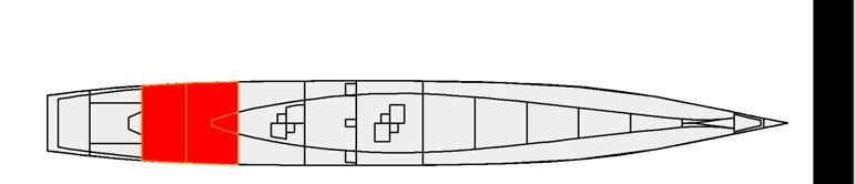
113 MSC Design VT Team 3 Page 113 Figure 108 Full Load Damage Condition Figure 109 Full Load Damage Condition Righting Arm Figure 110 Full Load Damage Condition


114 MSC Design VT Team 3 Page 114 Figure 111 Full Load Damage Condition Righting Arm Figure 112 MinOp Damage Condition Figure 113 MinOp Damage Condition Righting Arm
115 MSC Design VT Team 3 Page Seakeeping, Maneuvering and Control To get the seakeeping, maneuvering and control HECSALV and SMP were used. Using the offsets created in HecSalv that can be seen in section 4.4.1, a pre-smp processor was used to import the offsets, loads, sea-states, responses, motion points and relative points. Once this file was saved and executer, it would create an input file that was to be used in SMP, after some editing of the file. The next step was to input the appendages onto the model, such as the bilge keel, the skeg and the rudders. After the appendages were loaded, the irregular wave input file had to be adjusted in SMP to edit the general information used as well as the ship responses used. Then, the speed polar files, each of the testing conditions, had to be input into SMP. Once the conditions were input, it is possible to see the contour plots showing the seakeeping aspects for the ship at each testing condition. The limiting criteria for the ship can be seen below in Table 53. Table 53 Selected Seakeeping Limiting Criteria Application Sea State Location Roll Pitch V Vel L Acc T Acc V Acc Slam Wet 1. Bow Wetness 7 Bow Sta 0 30/hr 2. Keel Slam 7 Keel Sta 3 20/hr 3. VLS Launch 6 NA 17.5 deg 4. VLS Launch 6 NA 3 deg 5. VLS Launch 6 CG 0.3g 6. VLS Launch 6 CG 0.7g 7. VLS Launch 6 CG 0.6g 8. Radar 7 NA 25 deg 9. Bow Sonar 6 NA 15 deg 10. Bow Sonar 6 NA 5 deg 11. Gun 5 NA 7.5 deg 12. Gun 5 NA 7.5 deg 13. Gun 5 CG 1 m/s 14. Torpedo Launch 5 NA 7.5 deg 15. UNREP 5 NA 4 deg 16. UNREP 5 NA 1.5 deg 17. Helo 5 NA 5 deg 18. Helo 5 NA 3 deg 19. Helo 5 Landing 2 m/s 20. Personnel 7 NA 8 deg 21. Personnel 7 NA 3 deg 22. Personnel 7 Bridge 0.4g Some of the contour plots for the testing conditions can be seen below, with a color scale on the right. For each of the cases with the same sea state, only one image is provided, because they have the same output. The difference between each case is only the limit that can be sustained when underway.
116 MSC Design VT Team 3 Page c Figure 114 Case 1 Bow wetness at Sea State Figure 115 Case 2 Keel Slamming at Sea-State 7
117 MSC Design VT Team 3 Page Figure 116 Cases 3, 9 Roll for VLS Launch and Bow Sonar at Sea-State Figure 117 Cases 4, 10 Pitch for VLS Launch and Bow Sonar at Sea-State 6
118 MSC Design VT Team 3 Page Figure 118 Case 5 Longitudinal Acceleration for VLS Launch at Sea-State Figure 119 Case 6 Lateral Acceleration for VLS Launch at Sea-State 6
119 MSC Design VT Team 3 Page Figure 120 Case 7 Vertical Acceleration for VLS Launch at Sea-State Figure 121 Cases 8, 20 Roll for Sonar and Personnel at Sea-State 7
120 MSC Design VT Team 3 Page Figure 122 Cases 11, 14, 15 and 17 Roll for the Gun, Torpedo Launch, UNREP and Helo Operations at Sea- State 5 Figure 123 Cases 12 16, 18 Pitch for the Gun, UNREP, and Helo Operations at Sea-State
121 MSC Design VT Team 3 Page Figure 124 Cases 13 and 19 Vertical Velocity for the Gun and Helo Operations at Sea State Figure 125 Case 21 Pitch for Personnel at Sea-State 7
122 MSC Design VT Team 3 Page Figure 126 Case 22 Vertical Acceleration for Personnel at Sea-State 7 For each of the cases, the areas of operation can be seen below in Table 54. Table 54 Seakeeping Limiting Criteria and Areas of Operation Application Sea State Threshold Assessment 1. Bow Wetness (submergence/hr) 7 Limited to beam and following seas 2. Keel Slam (Slam/hr) 7 Limited to beam and following seas 3. VLS Launch (Roll) 6 Fully Operational 4. VLS Launch (Pitch) 6 Fully Operational 5. VLS Launch (Longitudinal Acceleration) 6 Fully Operational 6. VLS Launch (Lateral Acceleration) 6 Fully Operational 7. VLS Launch (Vertical Acceleration) 6 Fully Operational 8. Radar (Roll) 7 Fully Operational 9. Bow Sonar (Roll) 6 Fully Operational 10. Bow Sonar (Pitch) 6 Fully Operational 11. Gun (Roll) 5 Fully Operational 12. Gun (Pitch) 5 Fully Operational 13. Gun (Vertical Velocity) 5 Exceeds limit in head and beam seas of 20 knots 14. Torpedo Launch (Roll) 5 Fully Operational 15. UNREP (Roll) 5 Exceeds limit in beam seas less than 25 knots 16. UNREP (Pitch) 5 Fully Operational 17. Helo (Roll) 5 Fully Operational 18. Helo (Pitch) 5 Fully Operational 19. Helo (Vertical Velocity) 5 Fully Operational 20. Personnel (Roll) 7 Exceeds limit in beam seas less than 25 knots
123 MSC Design VT Team 3 Page Personnel (Pitch) 7 Exceeds limit in head seas 22. Personnel (Vertical Acceleration) 7 Fully Operational 4.12 Cost and Risk Analysis As part of the multi-objective optimization performed, cost was estimated for both lead and follow ship using parametric mathematical models. These models use the estimates of weights for different SWBS groups, along with other variables to estimate a cost of basic construction. Other variables considered were ships service life, total number of ships produced, base fiscal year with accounted inflation, crew, and total engine power. Estimates for government costs, change orders, shipbuilder profit, and several other capital-consuming costs were added to determine final cost estimates. The total cost estimate and cost breakdown for the lead ship as well as the follow ship are shown in Table 55. The total government portion cost along with the breakdown of costs for the lead and follow ships are shown in Table 56. The total cost estimates along with a general breakdown of costs are shown in Table 57. The undiscounted vs. discounted costs for the life time of the ship are shown in Table 58. Table 55 Follow Ship Cost Lead Ship Cost SWBS Total FS Construction Profit Shipbuilder Price Change Orders Total Shipbuilder Portion Table 56 Follow Ship Cost Lead Ship Cost Other Support Programs Managers Growth Payload GFE HM&E GFE Outfitting Total Gov't Portion Table 57 Follow Ship Cost Lead Ship Cost Total Shipbuilder Portion Total Gov't Portion Total Lead Ship End Cost Post Delivery Cost Total Lead Ship Acquisition Cost Average Ship Acquisition Cost 2630
124 MSC Design VT Team 3 Page 124 Table 58 Undiscounted Discounted R&D Costs ,659 Investment 98,622 29,153 Operations and Support 122,000 5,911 Residual Value 5, Total 218,500 37,705
125 MSC Design VT Team 3 Page Conclusions and Future Work 5.1 Assessment Technical Performance Measure Table 59 - Compliance with Operational Requirements CCD KPP Original Goal (Threshold) AAW/BMD AAW/SEW=3 AAW/SEW=1 Improved Baseline Final Baseline ASUW/NSFS ASUW=3 ASUW=1 C4ISR C4I=2 C4I=1 Vs (Sustained Speed) Ts (Provisions) Vs (Sustained Speed) Es (Endurance range at 20 kt) Future Work Adjust Preliminary Tankage and Structures Adjust Arrangements Damage Stability 5.3 Conclusions This hybrid/tumblehome medium surface combatant is the best of all worlds when risk and cost are used as the primary sources motivating the ship design. The flared hull allows for a very stable ship in many different sea states because of the large beam at the waterline. Above the waterline a radar cross section reducing tumblehome was utilized so this ship has the best of all worlds. This MSC has fairly high lead ship costs, but its modularity capabilities allow it to perform effectively for the life of the ship making it well worth it. As new technologies become available they can be installed and utilized quickly.
126 MSC Design VT Team 3 Page 126 References 1. Advanced Enclosed Mast/Sensor (AEM/S) The Federation of American Scientists. < 2. Beedall, Richard. Future Surface Combatant. September 10, < 3. Brown, Dr. Alan and LCDR Mark Thomas, USN. Reengineering the Naval Ship Concept Design Process Brown, A.J., Ship Design Notes, Virginia Tech AOE Department, Comstock, John P., ed. Principles of Naval Architecture, New Jersey: Society of Naval Architects and Marine Engineers (SNAME), Harrington, Roy L, ed. Marine Engineering. New Jersey: Society of Naval Architects and Marine Engineers (SNAME), Storch, Richard Lee. Ship Production. Maryland: Cornell Maritime Press, U.S. NavyFact File U.S. Navy Home Page Kennell, Colen, Design Trends in High-Speed Transport, Marine Technology, Vol. 35, No. 3, pp , July 1998.
127 MSC Design VT Team 3 Page 127 Appendix A Initial Capabilities Document (ICD) UNCLASSIFIED INITIAL CAPABILITIES DOCUMENT FOR A Medium Surface Combatant (MSC) 1 PRIMARY JOINT FUNCTIONAL AREAS Force and Homeland Protection - The range of military application for this function includes: force protection and awareness at sea; and protection of homeland and critical bases from the sea. Intelligence, Surveillance and Reconnaissance (ISR) - The range of military application for this function includes: onboard sensors; and support of manned and unmanned air, surface and subsurface vehicles. Power Projection - The range of military application for this function includes strike warfare and naval surface fire support. Operational timeframe considered: This extended timeframe demands flexibility in upgrade and capability over time. 2 REQUIRED FORCE CAPABILITY(S) Provide air, surface and subsurface defense around friends, joint forces and critical bases of operations at sea including BMD (multi-mission). Provide a sea-based layer of homeland defense, particularly BMD. Provide persistent surveillance and reconnaissance. Provide strike and naval surface fire support. These capabilities may be provided as a coordinated force, in support of a larger force, or individually with combinations of inherent multi-mission capabilities and tailored modular capabilities. Affordability is a critical issue which must enable sufficient force numbers to satisfy world-wide commitments consistent with national defense policy. In addition to providing necessary capabilities, rising acquisition, manning, logistics support, maintenance and energy costs must be addressed with a comprehensive plan including the application of new technologies, automation, modularity, and a necessary rational compromise of full multi-mission capabilities in all platforms. 3 CONCEPT OF OPERATIONS SUMMARY Ballistic Missile Defense (BMD). Current Aegis ships are being configured to intercept short and medium-range BM threats, but can not counter long-range intercontinental ballistic missiles that could target the US from China, North Korea and Iran. Current ships are also fully multi-mission ships. The radar and missile capabilities of some future surface combatants must be greater than the Navy s current Aegis ships. Some multi-mission capabilities may have to be sacrificed to control cost. Conducting BMD operations may require MSCs to operate in a location that is unsuitable for performing one or more other missions. Conducting BMD operations may reduce the ability to conduct air-defense operations against aircraft and cruise missiles due to limits on ship radar capacity. BMD interceptors may occupy ship weapon-launch tubes that might otherwise be used for air-defense, land-attack, or antisubmarine weapons. Maintaining a standing presence of a BMD ship in a location where other Navy missions do not require deployment, and where there is no nearby U.S. home port, can require a total commitment of several ships, to maintain ships on forward deployment. Critical capabilities for BMD-capable ships include high-altitude long-range search and track (LRS&T), and missiles with robust ICBM BMD terminal, mid-course, and potentially boost-phase capability. A ship with both of these is considered an ICBM engage-capable ship. The extent of these capabilities will have a significant impact on the ship s Concept of Operations. BMD requirements may change over time. Major Caliber Naval Surface Fire Support. There is a verified need for major caliber NSFS for the foreseeable future. DDG1000 was to provide this capability with the Advanced Gun System (AGS), but affordability issues may limit the number of these ships that can be built. An alternative strategy is required for placing one or two AGS on other MSCs, possibly as a modular system, and possibly without full multi-mission capability. These ships would operate with and ahead of marine amphibious task groups to prepare for and support marines operating from the sea. CSGs, ESGs and SAGs. It is expected that MSCs will continue to operate with Carrier Strike Groups and Expeditionary (Amphibious) Strike Groups providing AAW, ASUW and ASW support. MSC Surface Action Groups (SAGs) will perform various ISR and Strike missions in addition to providing their own AAW, ASUW and ASW defense. ISR missions will include the use of autonomous air surface and subsurface vehicles and LAMPS.

128 MSC Design VT Team 3 Page 128 Deployments will typically be have 6 month duration with underway replenishment, a few port visits, all-weather operations, cluttered air and shipping environments, blue water and littoral, and limited maintenance opportunities. MSCs will typically deploy and return to CONUS. 4 CAPABILITY GAP(S) The overarching capability gap addressed by this ICD is to provide demanding surface combatant capabilities in affordable medium surface combatant (MSC) ships ( MT). All capabilities may not be met in all MSCs at all times, but may be distributed over multiple ships at different times. Specific capability gaps and requirements include: Priority Capability Description Threshold Systems or metric Goal Systems or metric 5 THREAT AND OPERATIONAL ENVIRONMENT Ballistic missiles armed with WMD payloads pose a strategic threat to the United States. This is not a distant threat. A new strategic environment now gives emerging ballistic missile powers the capacity, through a combination of domestic development and foreign assistance, to acquire the means to strike the U.S. within about five years of a decision to acquire such a capability. During several of those years, the U.S. might not be aware that such a decision had been made. Available alternative means of delivery can shorten the warning time of deployment nearly to zero. The threat is exacerbated by the ability of both existing and emerging ballistic missile powers to hide their activities from the U.S. and to deceive the U.S. about the pace, scope and direction of their development and proliferation programs. Twenty-first-century threats to the United States, its deployed forces, and its friends and allies differ fundamentally from those of the Cold War. An unprecedented number of international actors have now acquired or are seeking to acquire ballistic and other types of missiles. These include not only states, but also non-state groups interested in obtaining missiles with nuclear or other payloads. The spectrum encompasses the missile arsenals already in the hands of Russia and China, as well as the emerging arsenals of a number of hostile states. The character of this threat has also changed. Unlike the Soviet Union, these newer missile possessors do not attempt to match U.S. systems, either in quality or in quantity. Instead, their missiles are designed to inflict major devastation without necessarily possessing the accuracy associated with the U.S. and Soviet nuclear arsenals of the Cold War. The warning time that the United States might have before the deployment of such capabilities by a hostile state, or even a terrorist actor, is eroding as a result of several factors, including the widespread availability of technologies to build missiles and the resulting possibility that an entire system might be acquired. Would-be possessors do not have to engage in the protracted process of designing and building a missile. They could purchase and assemble components or reverse-engineer a missile after having purchased a prototype, or immediately acquire a number of assembled missiles. Even missiles that are primitive by U.S. standards might suffice for a rogue state or terrorist organization seeking to inflict extensive damage on the United States. A successfully launched short or long range ballistic missile has a high probability of delivering its payload to its
Design Report. Ballistic Missile Defense Cruiser (CGX/BMD) VT Total Ship Systems Engineering
 VT Total Ship Systems Engineering") Design Report Ballistic Missile Defense Cruiser (CGX/BMD) VT Total Ship Systems Engineering CGX/BMD Variant 13 Ocean Engineering Design Project AOE 4065/4066 Fall 2007 Spring 2008 Virginia Tech Team 2
Design Report Ballistic Missile Defense Cruiser (CGX/BMD) VT Total Ship Systems Engineering CGX/BMD Variant 13 Ocean Engineering Design Project AOE 4065/4066 Fall 2007 Spring 2008 Virginia Tech Team 2
Virginia Tech DD-21 Destroyer Concept. David Woodward Ben Spina Jon Law Steve Darsie Andrew Girdler Jessica Smoldt
 Virginia Tech DD-21 Destroyer Concept David Woodward Ben Spina Jon Law Steve Darsie Andrew Girdler Jessica Smoldt Mission Needs Statement Dominance in independent and joint ops Mission and Threat Analysis
Design Report. Small Surface Large Combatant (SSC) VT Total Ship Systems Engineering
 VT Total Ship Systems Engineering") Design Report Small Surface Large Combatant (SSC) VT Total Ship Systems Engineering SSC Large Variant Ocean Engineering Design Project AOE 4065/4066 AOE 5314/5904 Fall 2009 Spring 2010 Virginia Tech Team
Design Report Small Surface Large Combatant (SSC) VT Total Ship Systems Engineering SSC Large Variant Ocean Engineering Design Project AOE 4065/4066 AOE 5314/5904 Fall 2009 Spring 2010 Virginia Tech Team
SEASPRITE. SH-2G Super MODERN MARITIME SOLUTION
 SEASPRITE SH-2G Super MODERN MARITIME SOLUTION Flexible The Kaman SH-2G Super Seasprite is the ideal multimission maritime helicopter. From anti-submarine warfare, to anti-surface warfare, over-the-horizon
DG-60M/540T BARBAROS Class PATROL BOAT ASuW, ASW, AAW
 (1 / 7) DESIGN : By DUZGIT GEMİ İNSA SAN. A.Ş. PLATFORM : Length OA = 60,00 mts Length BP = 55,50 mts Breadth mld = 8,90 mts Depth to main deck = 5,50 mts Design draft (mld) = 2,43 mts Design draft (extreme)
AUSTAL TRIMARAN TECHNOLOGY
 AUSTAL TRIMARAN TECHNOLOGY Bow view of the US Navy Littoral Combat Ship (LCS) Austal Trimaran Technology In 2000 Austal started a comprehensive research and development project with the objective to develop
International Diesel Electric Submarine Integrated Combat System
 International Diesel Electric Submarine Integrated Combat System International Diesel Electric Submarine Integrated Combat System Improving Allied Navies USW Capabilities Lockheed Martin Maritime Systems
UNCLASSIFIED UNCLASSIFIED
 BUDGET ACTIVITY: 3 PROGRAM ELEMENT: 6358N PROGRAM ELEMENT TITLE: Surface Ship & Submarine COST: (Dollars in Thousands) PROJECT NUMBER & FY 1999 TITLE ACTUAL FY 2 FY 21 FY 22 FY 23 FY 24 FY 25 TO COMPLETE
DDG 1000 Class Destroyer
 DDG 1000 Class Destroyer 10 January 2018 DDG 1000 Surface Navy Association (SNA) 30 th National Symposium DDG 1001 DDG 1000 Overview DDG 1002 DDG 1000 Program Manager, PMS 500 CAPT Kevin Smith 1 DDG 1000
CUVX Design Report Unmanned Combat Air Vehicle Carrier VT Total Ship Systems Engineering Approach
 CUVX Design Report Unmanned Combat Air Vehicle Carrier VT Total Ship Systems Engineering Approach CUVX HI2 Option Ocean Engineering Design Project AOE 4065/4066 Fall 2002 Spring 2003 Virginia Tech Team
Commercial Off the Shelf Ships for Naval Applications. By Peter Lucey Director Planning, Major Surface Combatants
 Commercial Off the Shelf Ships for Naval Applications By Peter Lucey Director Planning, Major Surface Combatants Disclaimer The information contained in this presentation is the opinion of the Author and
Statement of Jim Schoppenhorst, Director, DD(X) BAE Systems / Armament Systems Division. Before the
 BAE Systems / Armament Systems Division. Before the") Statement of Jim Schoppenhorst, Director, DD(X) BAE Systems / Armament Systems Division Before the House Armed Services Committee's Subcommittee on Projection Forces July 20, 2005 1 House Armed Services
Statement of Jim Schoppenhorst, Director, DD(X) BAE Systems / Armament Systems Division Before the House Armed Services Committee's Subcommittee on Projection Forces July 20, 2005 1 House Armed Services
SUPER LYNX 300. Anti-Submarine Warfare (ASW)
") Proven Force Multiplier SUPER LYNX 300 Anti-Submarine Warfare (ASW) MARITIME OPERATIONS Operating worldwide in all environments, the Super Lynx 300 ASW/ASuW extends the area capability and operational
Proven Force Multiplier SUPER LYNX 300 Anti-Submarine Warfare (ASW) MARITIME OPERATIONS Operating worldwide in all environments, the Super Lynx 300 ASW/ASuW extends the area capability and operational
UNCLASSIFIED FY 2017 OCO. FY 2017 Base
 Exhibit R-2, RDT&E Budget Item Justification: PB 2017 Air Force Date: February 2016 3600: Research, Development, Test & Evaluation, Air Force / BA 2: Applied Research COST ($ in Millions) Prior Years FY
Design Report. Agile Surface Combatant (ASC) VT Total Ship Systems Engineering
 VT Total Ship Systems Engineering") Design Report Agile Surface Combatant (ASC) VT Total Ship Systems Engineering Trimaran ASC-HI2 Option Ocean Engineering Design Project AOE 4065/4066 Fall 2003 Spring 2004 Virginia Tech Team 2 David Cash
Design Report Agile Surface Combatant (ASC) VT Total Ship Systems Engineering Trimaran ASC-HI2 Option Ocean Engineering Design Project AOE 4065/4066 Fall 2003 Spring 2004 Virginia Tech Team 2 David Cash
Power Converter Products. For Naval, Aviation and Land Applications
 Power Converter Products For Naval, Aviation and Land Applications Power Converter Products for Naval, Aviation and Land Applications Naval Today, advanced electronic power supply equipment supports critical
UNCLASSIFIED. FY 2016 Base FY 2016 OCO
 Exhibit R2, RDT&E Budget Item Justification: PB 2016 Navy : February 2015 1319: Research, Development, Test & Evaluation, Navy / BA 5: System Development & Demonstration (SDD) COST ($ in Millions) Years
1. Ship Name. 5. Type 6. Size Class/ Description. Damage Points. Surface Speed. Submerged Speed. Embarked Aircraft
 Ship Reference Sheet 3. Configuration Date Function 4. Class V 1. Ship 5. Type 6. Size Class Description age Point Effects Percent age % 25% 5% 75% 9% 1% Submerged Speed 7. Crew 8. Signature 2. Armor Class
UNCLASSIFIED. FY 2016 Base FY 2016 OCO
 Exhibit R-2, RDT&E Budget Item Justification: PB 2016 Air Force Date: February 2015 3600: Research, Development, Test & Evaluation, Air Force / BA 3: Advanced Technology Development (ATD) COST ($ in Millions)
UNCLASSIFIED R-1 ITEM NOMENCLATURE
 Exhibit R-2, RDT&E Budget Item Justification: PB 213 Navy DATE: February 212 COST ($ in Millions) FY 211 FY 212 FY 214 FY 215 FY 216 FY 217 To Program Element 67.48 18.248 99.6-99.6 49.2 12.2 13.4 -. 349.696
Project Spartan. An Innovative Light Frigate Design for General Purpose Frigate (GPFF)
") Project Spartan An Innovative Light Frigate Design for General Purpose Frigate (GPFF) The 2015 Strategic Defence and Security Review (SDSR) announced that the Royal Navy is looking to procure five light
Project Spartan An Innovative Light Frigate Design for General Purpose Frigate (GPFF) The 2015 Strategic Defence and Security Review (SDSR) announced that the Royal Navy is looking to procure five light
DESIGN DATA SHEET CALCULATION OF SURFACE SHIP ENDURANCE FUEL REQUIREMENTS DEPARTMENT OF THE NAVY NAVAL SEA SYSTEMS COMMAND WASHINGTON, DC
 DDS 200-1 REV 1 DESIGN DATA SHEET CALCULATION OF SURFACE SHIP ENDURANCE FUEL REQUIREMENTS DEPARTMENT OF THE NAVY NAVAL SEA SYSTEMS COMMAND WASHINGTON, DC 20376-5124 DISTRIBUTION STATEMENT A. APPROVED FOR
Using CREATE s Rapid Ship Design Environment to Perform Design Space Exploration for a Ship Design
 Using CREATE s Rapid Ship Design Environment to Perform Design Space Exploration for a Ship Design Adrian Mackenna Naval Surface Warfare Center, Carderock Division DISTRIBUTION STATEMENT: Distribution
Design Report. Littoral Warfare Submarine (SSLW) VT Total Ship Systems Engineering
 VT Total Ship Systems Engineering") Design Report Littoral Warfare Submarine (SSLW) VT Total Ship Systems Engineering Virginia Tech Ocean Engineering AOE 4065/4066 Fall 2004 Spring 2005 Team SCRAP Justin Chin Davy Hansch 19058 Nate Lambeth
Design Report Littoral Warfare Submarine (SSLW) VT Total Ship Systems Engineering Virginia Tech Ocean Engineering AOE 4065/4066 Fall 2004 Spring 2005 Team SCRAP Justin Chin Davy Hansch 19058 Nate Lambeth
Littoral Operations The UK Perspective. Captain C B Hodkinson MA Royal Navy
 Littoral Operations The UK Perspective Captain C B Hodkinson MA Royal Navy Aims of the Presentation Outline: Defining Operations in the Littoral Types of Operations in the Littoral UK Amphibious Capability
FIRST OF THE FRENCH BARRACUDA SUBMARINES IS READY FOR LAUNCH
 aut. Maksymilian Dura 20.05.2016 FIRST OF THE FRENCH BARRACUDA SUBMARINES IS READY FOR LAUNCH The hull, of the first French Barracuda-class submarine, has been moved to the ramp which is going to be used
WHEN BORDER SECURITY MATTERS
 WHEN BORDER SECURITY MATTERS WHEN BORDER SECURITY MATTERS Archangel performs long-range Intelligence, Surveillance and Reconnaissance (ISR) and standoff precision strike missions while maintaining a Common
Functional Decomposition of a Medium Voltage DC Integrated Power System
 Functional Decomposition of a Medium Voltage DC Integrated Power System ASNE SYMPOSIUM 2008 SHIPBUILDING IN SUPPORT OF THE GLOBAL WAR ON TERRORISM April 14-17, 2008 Mississippi Coast Coliseum Convention
NEW CREWING CONCEPT ON FREMM
 National Shipbuilding Procurement Strategy (NSPS) Workshop Series NEW CREWING CONCEPT ON FREMM Panel #2 Crewing: Exploration of new trends in the crewing of modern warships Nelly CHOUVY French MOD -DGA
ISSUE Construction and ROV Professionals Q2 / A Breakthrough in Hybrid Underwater Vehicles. The ECA Mine Counter Measure System
 8. A Breakthrough in Hybrid Underwater Vehicles 25. The ECA Mine Counter Measure System 31. The SeaTrepid Story 34. The Evolution of Single Beam Sonars for ROVs 11 The magazine of choice for Subsea ISSUE
NASA Glenn Research Center Intelligent Power System Control Development for Deep Space Exploration
 National Aeronautics and Space Administration NASA Glenn Research Center Intelligent Power System Control Development for Deep Space Exploration Anne M. McNelis NASA Glenn Research Center Presentation
UNCLASSIFIED R-1 ITEM NOMENCLATURE
 Exhibit R-2, RDT&E Budget Item Justification: PB 2013 Navy DATE: February 2012 COST ($ in Millions) FY 2011 FY 2014 FY 2015 FY 2016 FY 2017 To Program Element 7.969 7.896 8.090-8.090 8.047 8.220 8.288
AUTONOMOUS UNDERWATER VEHICLE DESIGNED TO BE USED IN ANTISUBMARINE WARFARE
 AUTONOMOUS UNDERWATER VEHICLE DESIGNED TO BE USED IN ANTISUBMARINE WARFARE Vasile DOBREF 1 Octavian TĂRĂBUŢĂ 2 Cătălin CLINCI 3 1 Captain, Assoc. Professor PhD, Mircea cel Batran Naval Academy, Constanta,
Comprehensive Motor and Control Solutions for Surface, Subsurface and Land-based Applications. Engineering Defense Supremacy
 Comprehensive Motor and Control Solutions for Surface, Subsurface and Land-based Applications Engineering Defense Supremacy Purpose-built Solutions That are the Benchmark in Performance, Productivity and
2016 Advisory Panel Electric Ship Technologies
 2016 Advisory Panel Electric Ship Technologies John Herbst Center for Electromechanics The University of Texas at Austin 5/10/2016 Research Significance Commercial efficiency driven 80-90% of world trade
MT30. Powering the world s future fleets
 MT30 Powering the world s future fleets 2008 marked the entry into service for the MT30 powering the US Navy s first Littoral Combat Ship, USS Freedom. The propulsion system features twin MT30 engines
MARAUDER LAND SYSTEMS ELECTRONIC SYSTEMS AEROSPACE LEADERS IN DEFENCE AND SECURITY INNOVATION
 MARAUDER LAND SYSTEMS ELECTRONIC SYSTEMS AEROSPACE LEADERS IN DEFENCE AND SECURITY INNOVATION LEADERS IN DEFENCE & SECURITY INNOVATION MARAUDER MULTI-ROLE, HIGHLY AGILE MINE-PROTECTED ARMOURED VEHICLE.
UNCLASSIFIED R-1 ITEM NOMENCLATURE. FY 2014 FY 2014 OCO ## Total FY 2015 FY 2016 FY 2017 FY 2018
 Exhibit R-2, RDT&E Budget Item Justification: PB 214 Navy DATE: April 213 COST ($ in Millions) Years FY 212 FY 213 # Base OCO ## FY 215 FY 216 FY 217 FY 218 To Program Element 72.343 17.721 29.897 27.154-27.154
Technology for the Future of Vertical Lift
 Presented to: Italian Vertical Lift Community Technology for the Future of Vertical Lift Approved for public release; distribution unlimited. Review completed by the AMRDEC Public Affairs Office 15 Nov
Danish frigate program. Setting a new standard for affordable defense procurement
 Danish frigate program Setting a new standard for affordable defense procurement Introduction to Danish frigate program The aim of the Danish frigate program is to provide the Royal Danish Navy with a
NAVAL FORCE MULTIPLIER
 AW159 NAVAL FORCE MULTIPLIER Building on the proven successful legacy of the Lynx family of helicopters, the AW159 is the next generation twin engine, multi-mission Maritime and Battlefield aircraft. The
AGM-114 Hellfire. Version: Basic Interim HF II Longbow Diameter: 7 in 7 in 7 in 7 in Weight: 100 lb 107 lb 100 lb 108 lb
 AGM-114 Hellfire The Hellfire Air-to-Ground Missile System (AGMS) provides heavy anti-armor capability for attack helicopters. The first three generations of HELLFIRE missiles use a laser seeker. The fourth
FIRST PICTURE OF CHINA'S SECRETIVE NEW SUBMARINE
 FIRST PICTURE OF CHINA'S SECRETIVE NEW SUBMARINE THE TYPE 093B IS STEALTHY AND NUCLEAR By Jeffrey Lin and P.W. Singer June 23, 2016 People's Navy Online TYpe 093B SSN The Type 093B SSN is China's newest
SOUND FLEET FACTS: SUSTAINED COMMITMENT, INCREASING CAPABILITIES
 SOUND FLEET FACTS: SUSTAINED COMMITMENT, INCREASING CAPABILITIES SERVS MISSION To maintain a constant state of readiness to assist tankers in the safe navigation through Prince William Sound, and to provide
GRC43m GLOBAL RESPONSE CUTTER
 GRC43m GLOBAL RESPONSE CUTTER SINCE 1964 RC43m ADVANCED PROVEN SOLUTIONS The Westport GRC43m (Global Response Cutter) affords military and government agencies a high quality executable program that will
AIAA Foundation Undergraduate Team Aircraft Design Competition. RFP: Cruise Missile Carrier
 AIAA Foundation Undergraduate Team Aircraft Design Competition RFP: Cruise Missile Carrier 1999/2000 AIAA FOUNDATION Undergraduate Team Aircraft Design Competition I. RULES 1. All groups of three to ten
neuron An efficient European cooperation scheme
 DIRECTION GÉNÉRALE INTERNATIONALE January, 2012 neuron An efficient European cooperation scheme I - INTRODUCTION 2 II - AIM OF THE neuron PROGRAMME 3 III - PROGRAMME ORGANISATION 4 IV - AN EFFICIENT EUROPEAN
2000/2001 AIAA FOUNDATION Undergraduate Team Aircraft Design Competition
 2000/2001 AIAA FOUNDATION Undergraduate Team Aircraft Design Competition I. RULES 1. All groups of 3 to 10 undergraduate AIAA branch or at-large Student Members are eligible and encouraged to participate.
CLASSIFICATION: UNCLASSIFIED. DATE May 2009 EXHIBIT R-2, RDT&E BUDGET ITEM JUSTIFICATION N/SUBMARINE TACTICAL WARFARE SYSTEM
 EXHIBIT R-2, RDT&E BUDGET ITEM JUSTIFICATION APPROPRIATION/BUDGET ACTIVITY R-1 ITEM NOMENCLATURE RDTEN/BA 5 0604562N/SUBMARINE TACTICAL WARFARE SYSTEM COST (In Millions) Total PE Cost 0236 / SSN Comb Cont
PM AAA NDIA Conference 25 October 2011
 PM AAA NDIA Conference 25 October 2011 1 AMPHIBIOUS VEHICLE WAY AHEAD Overarching Facts Joint Operational Access capability is required across the range of military operations 2 Marine Expeditionary Brigade
Open & Evolutive UAV Architecture
 Open & Evolutive UAV Architecture 13th June UAV 2002 CEFIF 16-juin-02 Diapositive N 1 / 000 Report Documentation Page Form Approved OMB No. 0704-0188 Public reporting burden for the collection of information
ABB's Energy Efficiency and Advisory Systems
 ABB's Energy Efficiency and Advisory Systems The common nominator for all the Advisory Systems products is the significance of full scale measurements. ABB has developed algorithms using multidimensional
SeaRobotics Facility. Integrated Facility for the Design and Build and Test. Location. Facility. Test Capability
 1 SeaRobotics Facility Location Located in Stuart, Florida 26 miles north of Riviera Beach ¼ mile from I-95 Facility 1400 square meters in Treasure Coast Commerce Park 400 m2, Engineering, Integration
Establishment of Light Tactical Vehicles Program Office
 1 Establishment of Light Tactical Vehicles Program Office Light Tactical Vehicles Portfolio Overview Programs Status, Issues, and Outlook Joint Light Tactical Vehicle (JLTV) High Mobility Multi-purpose
AMARA-CLASS MAIN HULL
 AMARA-CLASS MAIN HULL TL15 TONS COST (MCR) Hull 59,400 tons, Standard - 2,700 Reinforced - 1,350 Radiation Shielding - 1,350 Armour Bonded Superdense, Armour: 8 3,456 2,592 M-Drive Thrust 6 (assumes 75,000
Logistics Support Vessel HNoMS Maud. Sung Jin, Lee - DSME Ian Wakeling - BMT
 Logistics Support Vessel HNoMS Maud Sung Jin, Lee - DSME Ian Wakeling - BMT Contents THE LSV Team LSV Programme Status Key Features of the LSV Design RAS Hospital Aviation Mother Ship C4l Hull Form and
Reliable, Silent, Efficient. Voith Linear Jet
 Reliable, Silent, Efficient. Voith Linear Jet 1 A New Propulsion Standard. The Voith Linear Jet (VLJ) combines the best elements of two existing technologies conventional screw propellers and water jets.
Littoral Reconnaissance Ship
 Naval Surface Warfare Center Carderock Division West Bethesda, MD 20817-5700 NSWCCD-CISD 2008/010 July 2008 Ship Systems Integration & Design Directorate Technical Report by Scarlett Abrell and Andrew
UNCLASSIFIED. R-1 ITEM NOMENCLATURE PE N: Integrated Surveillance System FY 2012 OCO
 Exhibit R-2, RDT&E Budget Item Justification: PB 212 Navy DATE: February 211 COST ($ in Millions) FY 21 FY 211 PE 24311N: Integrated Surveillance System Total FY 213 FY 214 FY 215 FY 216 To Complete Total
MINE CLEARANCE, REMOTE CONTROL AND AREA DENIAL SYSTEMS SPECIAL PROJECTS
 MINE CLEARANCE, REMOTE CONTROL AND AREA DENIAL SYSTEMS SPECIAL PROJECTS Based firmly on Pearson Engineering s experience in defence and security, Special Projects offer customer oriented solutions across
FY 2018 FCT Projects
 FY 2018 FCT s 105mm Family of Multi-Purpose Munitions Evaluate advanced munitions for the Army s nextgeneration Mobile Protected Firepower platform Selectable munitions capable of defeating dismounts hiding
Sikorsky MH 60R SEAHAWK Helicopter Premier multi-mission maritime system
 Sikorsky MH 60R SEAHAWK Helicopter Premier multi-mission maritime system Premier The newest aircraft in the U.S. Navy fleet, the MH-60R SEAHAWK helicopter elevates tactical maritime mission capability
Subject: ARRV Underwater Radiated Noise Design Limit Date: 29 July, 2008
 Subject: ARRV Underwater Radiated Noise Design Limit Date: 29 July, 2008 References: 1. UNOLS Science Mission Requirements dated 2000/2001 2. ICES Cooperative Research Report No. 209 3. Measurement of
EW Engagement Modelling for Light Armoured Vehicles
 EW Engagement Modelling for Light Armoured Vehicles Vivienne Wheaton Electronic Warfare and Radar Division, DSTO Light Armoured Vehicles (LAVs) have many advantages in military operations but are significantly
HELICOPTERS Military. AS565 MBe
 HELICOPTERS Military AS565 MBe 002 AS565 MBe The AS565 MBe, The Naval Utility Helicopter at its best The AS565 MBe is the latest evolution of the combat proven Panther helicopter with more powerful engines
Focused Mission High Speed Combatant
 Focused Mission High Speed Combatant LT Erik Oller, USN LT Vasilios Nikou, HN LTJG Konstantinos Psallidas, HN May 9, 2003 13.414 Projects in New Construction Naval Ships Design Massachusetts Institute
Development of an Extended Range, Large Caliber, Modular Payload Projectile
 1 Development of an Extended Range, Large Caliber, Modular Payload Projectile April 12th, 2011 Miami, Florida, USA 46 th Annual Gun & Missile Systems Conference & Exhibition Speaker: Pierre-Antoine Rainville
Focus Areas Power and Energy Operational Environments
 Navy Energy Forum RADM Nevin P. Carr, Jr. Chief of Naval Research Presented by Dr. John Pazik, Director Ship System & Engineering Research Division Office of Naval Research 1 Naval S&T Strategic Plan Broad
RDT&E BUDGET ITEM JUSTIFICATION SHEET (R-2 Exhibit) February 2003
 February 2003") COST ($ in Thousands) Actual FY 2005 FY 2006 FY 2007 FY 2008 FY 2009 Cost to Total Cost 2671 F-16 Squadrons 107,035 81,639 87,478 99,867 111,954 120,079 111,450 113,519 Continuing TBD Quantity of RDT&E
COST ($ in Thousands) Actual FY 2005 FY 2006 FY 2007 FY 2008 FY 2009 Cost to Total Cost 2671 F-16 Squadrons 107,035 81,639 87,478 99,867 111,954 120,079 111,450 113,519 Continuing TBD Quantity of RDT&E
Chapter 8. Example Point Design - Suppression of Enemy Air Defenses
 Chapter 8 Example Point Design - Suppression of Enemy Air Defenses In order to quantify the sensitivity of UAVs to potential technological advances and to define promising UAVs as precisely as possible,
UT30MK2 & MT30 Unmanned and Manned Turrets
 ELBIT SYSTEMS - LAND AND C 4 I ARMORED VEHICLES SOLUTIONS UT30MK2 & MT30 Unmanned and Manned Turrets Combat-proven firepower for armored personnel carriers, fully overhead without compromising troop safety
Analysts/Fund Managers Visit 19 April Autonomous Systems and Future Capability Mark Kane
 Analysts/Fund Managers Visit 19 April 2007 Autonomous Systems and Future Capability Mark Kane The Rationale for UAVs The Rationale for UAVs UAVs generally seen to carry out the dull, dirty, and dangerous
Captain Lynn Petersen, USN PMS 320 Deputy Director 5 May 2011
 Advanced Power Systems for Enhanced Capability and Fuel Economy Captain Lynn Petersen, USN PMS 320 Deputy Director 5 May 2011 Agenda Fuel and Capability : Navy Leadership Perspective The Situation War
Visit Beechcraft.com or contact a defense company sales rep:
 AT-6 Visit or contact a defense company sales rep: +1.316.676.0800 Images may show optional equipment. 2013 Beechcraft Defense Company LLC. All rights reserved. Beechcraft is a registered trademark of
PEO USC. NAVSEA Small Business Industry Day. Mr. Nidak Sumrean PEO USC Executive Director. 21 August 2018
 PEO USC NAVSEA Small Business Industry Day 21 August 2018 Mr. Nidak Sumrean PEO USC Executive Director Transition to PEO USC 36 PEO USC Portfolio International Small Combatants In-Service Support (Ships
PHASE 4 OVERLANDER PROTECTED MOBILITY VEHICLE LIGHT
 226 DEFENCE CAPABILITY PLAN 2011 PUBLIC VERSION PROJECT NUMBER Overlander Protected Mobility Vehicle Light Overlander Medium and Heavy Tactical Training Vehicles LAND 121 Background Overlander is a multi-phased
THE PERFECT MOBILE VSHORAD SOLUTION
 THE PERFECT MOBILE VSHORAD SOLUTION Ground Based Air Defence System Solutions Anders Linder, Head of Surface Radar Solutions Michael Höglund, Head of Marketing & Sales, Missile Systems This document and
AW101. Maritime. The Superior Solution
 AW101 Maritime The Superior Solution EXTENDING THE LIMITS OF maritime operations The AW101 is the most advanced and capable multi-role maritime helicopter available today. The AW101 has proven its capability
GLOBALCOMMAND SERIES. A Global War 2nd Edition Expansion
 GLOBALCOMMAND SERIES A Global War 2nd Edition Expansion Alternate History Scenario Overview The Indian Ocean was a transit route for strategic raw materials flowing from British colonies as well a route
(C-10) (C-13) 6. GUNNERY COMBAT PHASE Players declare firing ships For each fire combat:
 (C-13) 6. GUNNERY COMBAT PHASE Players declare firing ships For each fire combat:") MICRONAUTS: THE GAME - WWII COMBAT TABLE CARDS Use this page to keep track of steps involved in each game phase. Tables are grouped on the following pages according to function. 1. INITIATIVE/COHESION
MICRONAUTS: THE GAME - WWII COMBAT TABLE CARDS Use this page to keep track of steps involved in each game phase. Tables are grouped on the following pages according to function. 1. INITIATIVE/COHESION
Prototyping Collision Avoidance for suas
 Prototyping Collision Avoidance for Michael P. Owen 5 December 2017 Sponsor: Neal Suchy, FAA AJM-233 DISTRIBUTION STATEMENT A: Approved for public release; distribution is unlimited. Trends in Unmanned
Multi-INT Manned Airborne ISR
 Multi-INT Manned Airborne ISR This briefing has been approved for release by LM IS&GS Export/Import Office. All exports, sales and offerings of the systems, products and solutions referenced herein are
Advanced Propulsion Technologies
 Advanced Propulsion Technologies For Electric Ship Architectures Sanjeev Kakkar Director Business Development Military Systems Operation GE Aviation sanjeev.kakkar@ge.com Warship Power Demands Energy Consuming
UNCLASSIFIED R-1 ITEM NOMENCLATURE. FY 2014 FY 2014 OCO ## Total FY 2015 FY 2016 FY 2017 FY 2018
 COST ($ in Millions) Years FY 2012 FY 2013 # ## FY 2015 FY 2016 FY 2017 FY 2018 To Program Element 335.638 51.642 9.122 3.326-3.326 1.396 0.930 0.279 0.284 0.000 402.617 675143: Predator 335.638 51.642
GRIPEN FUTURE DEVELOPMENT
 ICAS 2002 CONGRESS GRIPEN FUTURE DEVELOPMENT Gert Sjunnesson Saab Aerospace, Gripen S 581 88 Linköping, Sweden Abstract Further development and enhancement of the Gripen Weapon System is a continuous process.
Design Criteria and Practices for the Electric Warship
 Dr. Norbert Doerry Design Criteria and Practices for the Electric Warship ABSTRACT NAVSEA T9300-AF-PRO-020 is the U.S. Navy s design practices and criteria manual for design of surface ship electrical
MULTI-MISSION FAMILY OF VEHICLES M-ATV INNOVATION DRIVES FORWARD
 MULTI-MISSION FAMILY OF VEHICLES M-ATV INNOVATION DRIVES FORWARD 2 This is Oshkosh Defense. 3 At Oshkosh Defense, we stand behind those who dedicate their lives to protecting others. Every day we strive
Defense Green Technology of KOREA
 Defense Green Technology of KOREA March 18th 2010 Dr. In Woo Kim Agency for Defense Development 1 Contents Introduction of ADD Mission To Research, Develop, Test and Evaluate Weapon systems, Equipments,
About TECO-Westinghouse
 About TECO-Westinghouse Th e TECO-WESTINGHOUSE l e g ac y o f i n n ovat i o n a n d q ua l i t y in the design and production of electric motors and generators for the marine industry spans more than
UNCLASSIFIED R-1 ITEM NOMENCLATURE FY 2013 OCO
 Exhibit R-2, RDT&E Budget Item Justification: PB 213 Navy DATE: February 212 COST ($ in Millions) FY 211 FY 212 FY 214 FY 215 FY 216 FY 217 To Program Element 58.638 67.569 31.15-31.15 47.226 46.85 47.56
fincantieri / marine systems and components Controllable and Fixed Pitch Propellers
 fincantieri / marine systems and components Controllable and Fixed Pitch Propellers Propellers System The largest shipbuilding group in the Mediterranean area, Fincantieri has more than fifty years of
Jay Gundlach AIAA EDUCATION SERIES. Manassas, Virginia. Joseph A. Schetz, Editor-in-Chief. Blacksburg, Virginia. Aurora Flight Sciences
 Jay Gundlach Aurora Flight Sciences Manassas, Virginia AIAA EDUCATION SERIES Joseph A. Schetz, Editor-in-Chief Virginia Polytechnic Institute and State University Blacksburg, Virginia Published by the
Exhibit R-2, RDT&E Budget Item Justification
 PE NUMBER: 0305219F PE TITLE: PREDATOR Exhibit R-2, RDT&E Budget Item Justification BUDGET ACTIVITY PE NUMBER AND TITLE Cost ($ in Millions) FY 2008 FY 2009 FY 2010 FY 2011 FY 2012 FY 2013 FY 2014 FY 2015
United Stales COMDPTPUB P Coast Guard NVIC Mar 191
 United Stales COMDPTPUB P16700.4 Coast Guard NVIC 5-91 8 Mar 191 NAVIGATION AND VESSEL INSPECTION CIRCULAR NO. 5-91 Electronic Version for Distribution on the World Wide Web Subi: Inspection and Certification
DCNS believes that the sea is this planet s future
 DCNS believes that the sea is this planet s future Corporate communications About DCNS 2 Corporate Communications DCNS. A world leader in naval defence. An innovative player in energy. 3 Corporate Communications
Joint Light Tactical Vehicle Power Requirements
 Joint Light Tactical Vehicle Power Requirements DISTRIBUTION STATEMENT A: Approved for public release; distribution is unlimited Ms. Jennifer Hitchcock Associate Director of Ground Vehicle Power and 1
Review of the Technical Specifications for the BCFS Intermediate Class Ferry and the provisions of the BC Ferry Commission Order 13-01
 BC Ferry Commission First Floor, 1312 Blanshard Street P.O. Box 9279 Victoria, British Columbia V8W 3S2 3GA Marine Ltd 505-827 Fairfield Road Victoria British Columbia V8V 5B2 Review of the Technical Specifications
Integrated Airborne Surveillance Systems. November 2014
 Integrated Airborne Surveillance Systems November 2014 Integrated Airborne Surveillance Systems ATOS Mission System for Manned Platforms Unmanned Aerial Systems (UAS) 2 ATOS Mission System ATOS (Airborne
CITY OF MINNEAPOLIS GREEN FLEET POLICY
 CITY OF MINNEAPOLIS GREEN FLEET POLICY TABLE OF CONTENTS I. Introduction Purpose & Objectives Oversight: The Green Fleet Team II. Establishing a Baseline for Inventory III. Implementation Strategies Optimize
Predator B: The Multi-Role UAV
 Predator B: The Multi-Role UAV June 2002 Report Documentation Page Form Approved OMB No. 0704-0188 Public reporting burden for the collection of information is estimated to average 1 hour per response,