THE POWER OF T&B ENGINEERED PRODUCTS AND SERV- ICES
|
|
|
- Loreen Evans
- 5 years ago
- Views:
Transcription

1 Thomas & BettsMORE POWER TO YOU For over 70 years, Canadian electrical contractors, plant engineers and engineering consultants have placed their trust in Thomas & Betts electrical components. Today, Thomas & Betts Ltd. offers a complete package of market-driven products and services designed to give you the power to succeed in today s economy. THE POWER OF T&B ENGINEERED PRODUCTS AND SERV- ICES Our products and services continue to set new standards for quality, reliability and innovation. Highly-focused sales, product support and customer service teams dedicated to serving the commercial, industrial MRO and OEM markets. Guaranteed, competitive pricing. The broadest offering of field-proven, brand name products available from one manufacturer. One order, one shipment for thousands of standard products through Thomas & Betts and your Signature Service distributor. Reduced lead time on critical products through your Signature Service distributor. Technical support via phone, fax on demand and the Internet. T&B Access provides electrical distributors with the answers they need, online 24/7. ISO-certified manufacturing - quality engineering and manufacturing. Local and national inventory support. T&B Tool Lease program - the tools you need today without tomorrow s investment.

2 THE POWER OF CHOICE As North America s largest single source for electrical components, Thomas & Betts is powered by the longest and most complete list of reputable brand name products available from one manufacturer in the industry today. With services like one order, one shipment available through your Thomas & Betts distributor, the more T&B purchases you make, the more you can save. To request information about any of these products, contact your Regional Sales Office. All-Struct Amerace Battpac Blackburn Blackburn Color-Keyed Deltec Diamond Elastimold Emergi-Lite ExpressTray E-Z-Code E Z Ground Furseweld Hazlux Iberville Iberville Kold-n-Klose LRC Lumacell Marrette Meyer Microlectric Mipco NuTek Ocal Partex Pos-E-Kon Ready-Lite Red Dot Reznor Russellstoll Sachs Shield-Kon Shrink-Kon South River Sta-Kon StarTeck Superstrut T&B T&B Taylor Ty-Fast Ty-Rap TM TM TM TM TM TM TM TM TM TM TM TM TM TM TM TM aluminum structures airfield lighting battery-powered and compression tools compression connectors grounding products compression connectors aerial cable support systems pole line hardware premolded connectors for underground distribution applications emergency lighting systems wire-mesh cable management system wire marker systems compression connectors exothermic connectors hazardous location lighting roughing-in products steel boxes and covers forced encapsulated closures and sheath repair systems connectors, splices, adaptors and accessories emergency lighting systems wire connectors transmission and light duty engineered steel poles meter sockets and pole line hardware plugs, receptacles, modules, power outlets and connectors nonmetallic boxes coated products wire marker systems industrial connectors emergency lighting systems weatherproof boxes and covers heating, ventilation and cooling systems plugs, receptacles and connectors drop line and construction hardware, grounding and bonding products, signal security hardware grounding connectors and tools insulation products wireless antenna mounts and hardware terminals and application tools fittings for teck cable metal framing, channel and accessories cable tray systems conduit fittings wiring ducts cables ties cables ties Every effort is made to ensure the accuracy of the information contained in this catalogue at the time of publication. As part of our ongoing quality control program, we actively encourage customer input. Should you have any comments regarding the content of our catalogues, please forward via to mrkt_canada@tnb.com or contact your Thomas & Betts sales representative.
3 TABLE OF CONTENTS Why specify our cable tray...2 Technical information...5 Corrosion guide CSA & NEMA loading classes...8 Technical information Installation guidelines...11 Technical information...12 Sample recommended specifications...13 Applications photos...14 Straight sections...15 Straight section numbering system straight section straight section straight section Fittings...23 Fitting numbering system...25 Horizontal bends...26 Horizontal tee & cross...29 Horizontal reducing/expanding tee...32 Horizontal expanding/reducing cross...37 Reducers...40 Vertical Bends...43 Vertical Tees...46 Accessories...49 Cable Channel...57 Non-metallic strut systems...61 TECHNICAL INFORMATION STRAIGHT SECTIONS ACCESSORIES FITTINGS CABLE CHANNEL SYSTEM Other Products...79 NON-METALLIC STRUT SYSTEMS 1


4 WHY SPECIFY OUR CABLE TRAY? Non-metallic Cable Tray Systems have been tested and proven in the harsh environment of the offshore oil and gas industry. Subject to the corrosive conditions inherent in petroleum products, plus the daily punishment of exposure to wind, weather and saltwater Non-metallic Cable Tray has stood up! Non-metallic Cable Tray gives you the load capacity of steel plus the inherent characteristics afforded by our Pultrusion Technology: non conductive, non magnetic and corrosion-resistant. Although light in weight, their strength-to-weight ratio surpasses that of equivalent steel products. Non-metallic Cable Tray will not rust, nor does it ever require painting. Available in both polyester and vinylester resin systems, they are manufactured to meet ASTM E-84, Class 1 Flame Rating and self-extinguishing requirements of ASTM D-635. The CSA/NEMA loadings, both listed in this brochure, are load-tested in accordance with NEMA/CSA guidelines. Non-Metallic Cable Tray comes in two colors : Slate grey (polyester resin) and Beige (vinyl ester resin). Custom colors are available on request. Veil Mat Unidirectionally aligned glass fibers bonded with resin Polyester or vinyl ester surface A surface veil is applied during the pultrusion process to ensure a resin-rich surface for superior corrosion resistance as well as an ultraviolet exposure barrier. 2
5 section 1 TECHNICAL INFORMATION

6
7 TECHNICAL INFORMATION TYPICAL PROPERTIES OF PULTRUDED COMPONENTS Thomas & Betts Non-Metallic Cable Tray systems are manufactured from glass fiber-reinforced plastic shapes that meet ASTM E-84, Class 1 Flame Rating and self-extinguishing requirements of ASTM D-635. A surface veil is applied during pultrusion to insure a resin-rich surface and ultraviolet resistance. TECHNICAL INFORMATION 3" & 4" Cable Tray, Test Unit/ Cable Channel 6" Cable Tray Properties Method Value Longitudinal Transverse Longitudinal Transverse Tensile Strength ASTM D638 psi 30,000 7,000 40,000 4,500 Tensile Modulus ASTM D638 psi x Flexural Strength ASTM D790 psi 30,000 10,000 40,000 10,000 Flexural Modulus ASTM D790 psi x Izod Impact ASTM D256 ft-lbs/in Compressive Strength ASTM D695 psi 30,000 15,000 40,000 10,000 Compressive Modulus ASTM D695 psi x Barcol Hardness ASTM D Shear Strength ASTM D732 psi 5,500 5,500 5,500 5,500 Density ASTM D1505 lbs/in Coefficient of Thermal Expansion ASTM D696 in/in/ F 5.0 x x Water Absorption ASTM D570 Max % Dielectic Strength ASTM D149 V/mil (vpm) Flammability Classification UL94 VO Flame Spread ASTM E Max FLAME RATING RESULTS Test Ignition Burning Rating Flame Resistance (FTMS ) 75 seconds 75 seconds - Intermittent Flame Test (HLT- 15) Flammability Test (ASTM D635) None 0 second - 5
8 CORROSION GUIDE The information shown in this corrosion guide is based on full immersion laboratory tests and data generated from resin manufacturers. It should be noted that in some of the environments listed, splashes and spills may result in a more corrosive situation than indicated due to the evaporation of water. Regular wash down is recommended in these situations. All data represents the best available information and is believed to be correct. The data should not be construed as a warranty of performance for that product as presented in these tables. User tests should be performed to determine suitability of service if there is any doubt or concern. Such variables as concentration, temperature, time of exposure and combined chemical effects of mixtures of chemicals make it impossible to specify the exact suitability of fiber-reinforced plastics in all environments. Thomas & Betts will be happy to supply material samples for testing. These recommendations should only be used as a guide and Thomas & Betts does not take responsibility for design or suitability of materials for service intended. In no event will Thomas & Betts be liable for any consequential or special damages for any defective material or workmanship including, without limitation, labor charges or other expenses or damage to property resulting from loss of materials or profits or increased expenses of operations. POLYESTER VINYL ESTER CHEMICAL Max Max Oper. Max Max Oper. ENVIRONMENT Wt. % Temp F Wt. % Temp F Acetic Acid Acetic Acid Acetone N/R N/R Aluminum Chloride SAT 170 SAT 200 Aluminum Hydroxide SAT 160 SAT 170 Aluminum Nitrate SAT 150 SAT 170 Aluminum Sulfate SAT 180 SAT 200 Ammonium Chloride SAT 170 SAT 190 Ammonium Hydroxide Ammonium Hydroxide 28 N/R Ammonium Carbonate N/R N/R SAT 150 Ammonium Bicarbonate SAT 130 Ammonium Nitrate SAT 160 SAT 190 Ammonium Persultate SAT N/R SAT 150 Ammonium Sulfate SAT 170 SAT 200 Amyl Alcohol ALL N/R ALL 90 Amyl Alcohol Vapor Benzene N/R N/R Benzene Sulfonic Acid SAT 200 Benzoic Acid SAT 150 SAT 200 Benzoyl Alcohol 100 N/R 100 N/R Borax SAT 170 SAT 200 Calcium Carbonate SAT 170 SAT 200 Calcium Chloride SAT 170 SAT 200 Calcium Hydroxide Calcium Nitrate SAT 180 SAT 200 Calcium Sulfate SAT 180 SAT 200 Carbon Disulfide N/R N/R N/R N/R Carbonic Acid SAT 130 SAT 180 Carbon Dioxide Gas Carbon Monoxide Gas Carbon Tetrachloride N/R N/R Chlorine, Dry Gas Chlorine, Wet Gas - N/R Chlorine Water SAT 80 SAT : No Information Available N/R : Not Recommended SAT : Saturated Solution FUM : Fumes POLYESTER VINYL ESTER CHEMICAL Max Max Oper. Max Max Oper. ENVIRONMENT Wt. % Temp F Wt. % Temp F Chromic Acid Citric Acid SAT 170 SAT 200 Copper Chloride SAT 170 SAT 200 Copper Cyanide SAT 170 SAT 200 Copper Nitrate SAT 170 SAT 200 Crude Oil, Sour Cyclohexane N/R N/R N/R N/R Cyclohexane, Vapor ALL 100 ALL 130 Diesel Fuel Diethyl Ether N/R N/R N/R N/R Dimethyl Phthalate N/R N/R N/R N/R Ethanol Ethyl Acetate N/R N/R N/R N/R Ethylene Chloride N/R N/R N/R N/R Ethylene Glycol Fatty Acids SAT 180 SAT 200 Ferric Chloride SAT 170 SAT 200 Ferric Nitrate SAT 170 SAT 200 Ferric Sulfate SAT 170 SAT 200 Ferrous Chloride SAT 170 SAT 200 Fluoboric Acid N/R N/R SAT 165 Fluosilicic Acid N/R N/R SAT 70 Formaldehyde Formic Acid N/R N/R Gasoline Glucose Glycerine Heptane Hexane Hydrobromic Acid Hydrochloric Acid Hydrochloric Acid Hydrochloric Acid Hydrochloric Acid N/R N/R Hydrogen Bromide, Dry
9 CORROSION GUIDE POLYESTER VINYL ESTER CHEMICAL Max Max Oper. Max Max Oper. ENVIRONMENT Wt. % Temp F Wt. % Temp F Hydrogen Bromide, Wet Hydrogen Chloride Hydrogen Peroxide Hydrogen Sulfide, Dry Hydrogen Sulfide, Wet Hypochlorous Acid Isopropyl Alcohol N/R N/R Kerosene Lactic Acid SAT 170 SAT 200 Lead Acetate SAT 170 SAT 200 Lead Chloride SAT 140 SAT 200 Lead Nitrate SAT - SAT 200 Linseed Oil Lithium Chloride SAT 150 SAT 190 Magnesium Carbonate SAT 140 SAT 170 Magnesium Chloride SAT 170 SAT 200 Magnesium Hydroxide SAT 150 SAT 190 Magnesium Nitrate SAT 140 SAT 180 Magnesium Sulfate SAT 170 SAT 190 Mercuric Chloride SAT 150 SAT 190 Mercurous Chloride SAT 140 SAT 180 Methyl Ethyl ketone N/R N/R N/R N/R Mineral Oils Monochlorobenzene N/R N/R N/R N/R Naphtha Nickel Chloride SAT 170 SAT 200 Nickel Nitrate SAT 170 SAT 200 Nickel Sulfate SAT 170 SAT 200 Nitric Acid Nitric Acid Oleic Acid Oxalic Acid ALL 75 ALL 120 Paper Mill Liquors Perchlorethylene 100 N/R 100 N/R Perchloric Acid N/R N/R Perchloric Acid N/R N/R Phosphoric Acid Phosphoric Acid Potassium Alum. Sulfate SAT 170 SAT 200 Potassium Bicarbonate Potassium Bichromate SAT 170 SAT 200 Potassium Carbonate 10 N/R Potassium Chloride SAT 170 SAT : No Information Available N/R : Not Recommended SAT : Saturated Solution FUM : Fumes POLYESTER VINYL ESTER CHEMICAL Max Max Oper. Max Max Oper. ENVIRONMENT Wt. % Temp F Wt. % Temp F Potassium Hydroxide N/R N/R Potassium Nitrate SAT 170 SAT 200 Potassium Permanganate Potassium Sulfate SAT 170 SAT 200 Propylene Glycol ALL 170 ALL 200 Phthalic Acid - - SAT 200 Sodium Acetate SAT 160 SAT 200 Sodium Benzoate SAT 170 SAT 200 Sodium Bicarbonate SAT 160 SAT 175 Sodium Bisulfate ALL 170 ALL 200 Sodium Bromide ALL 170 ALL 200 Sodium Carbonate Sodium Chloride SAT 170 SAT 200 Sodium Cyanide SAT 170 SAT 200 Sodium Hydroxide N/R N/R Sodium Hydroxide N/R N/R Sodium Hypochloride N/R N/R Sodium Monophosphate SAT 170 SAT 200 Sodium Nitrate SAT 170 SAT 200 Sodium Sulfate SAT 170 SAT 200 Sodium Thiosulfate ALL 100 ALL 120 Stannic Chloride SAT 160 SAT 190 Styrene N/R N/R N/R N/R Sulfated Detergent 0/ / Sulfur Dioxide Sulfur Trioxide Sulfuric Acid 93 N/R 93 N/R Sulfuric Acid 50 N/R Sulfuric Acid Sulfurous Acid SAT 80 N/R N/R Tartaric Acid SAT 170 SAT 200 Tetrachloroethylene N/R N/R FUM 75 Toluene N/R N/R N/R N/R Trisodium Phosphate N/R N/R SAT 175 Urea SAT 130 SAT 140 Vinegar Water, Distilled Water, Tap Water, Sea SAT 170 SAT 190 Xylene N/R N/R N/R N/R Zinc Chloride SAT 170 SAT 200 Zinc Nitrate SAT 170 SAT 200 Zinc Sulfate SAT 170 SAT 200 TECHNICAL INFORMATION 7
10 CSA & NEMA LOADING CLASSES LOADING Select the Tray Class / Load Capacity The standard classes of cable trays, as related to their maximum design loads and to the associated design support spacing based on a simple beam span requirement, shall be designated in accordance with Table 1. Please note the load ratings in Table 1 are those most commonly used. Other load ratings are acceptable. TABLE 1 LOAD / SPAN CLASS DESIGNATIONS Load Span, m (ft) kg/m (lb/ft) 2.4 (8) 3.0 (10) 3.7 (12) 4.9 (16) 6.0 (20) 37 (25) - A (45) D 74 (50) 8A - 12A 16A 20A 97 (65) - C (75) 8B - 12B 16B E or 20B 149 (100) 8C - 12C 16C 20C 179 (120) - D (200) - E Deflection Span TABLE 2 CONVENTIONAL CSA LOAD DESIGNATIONS Designation kg/m (lb/ft) A 37 (25) C 97 (65) D 179 (120) E 299 (200) TABLE 3 TRADITIONAL NEMA DESIGNATIONS Designation kg/m (lb/ft) Designation kg/m (lb/ft) Designation kg/m (lb/ft) Designation kg/m (lb/ft) 8A 64 (50) 12A 74 (50) 16A 74 (50) 20A 74 (50) 8B 112 (75) 12B 112 (75) 16B 112 (75) 20B 112 (75) 8C 149 (100) 12C 149 (100) 16C 149 (100) 20C 149 (100) 8
11 TECHNICAL INFORMATION LOADING CAPACITY Strength properties of reinforced plastics are reduced when continuously exposed to elevated temperatures. Working loads shall be reduced based on the following: TECHNICAL INFORMATION Cable Loads Snow Loads Ice Loads Wind Loads The cable load is the total weight, expressed in lb./ft., of all the cables that will be placed in the cable tray. Depending on the area, snowfall could indicate an additional design load. If snowfall is a factor and the tray has a solid cover in outdoor installations, a minimum load of 5 lb. per square foot should be used. If a cable tray system is subject to icing conditions, usually only the top surface or cover and the windward side will be coated with any significant amount. It is generally assumed that ice weighs 57 lb. per cubic foot. All outdoor cable tray installations should factor in wind loads, especially the pressure exerted on siderails of ladder trays. There have also been instances of strong winds lifting covers off trays, which can be minimized with the use of wraparound cover clamps. CONCENTRATED LOADS A concentrated static load is not included in Table 1 (page 8). Some user applications may require that a given concentrated static load be imposed over and above the working load. Such a concentrated static load represents a static weight applied on the centerline of the tray at midspan. When so specified, the concentrated static load may be converted to an equivalent uniform load (W e ) in kilograms/metre (pounds/linear foot), using the following formula, and added to the static weight of cable in the tray: W e = 2 X (concentrated static load, kg (lb.)) Span length, m (ft.) This combined load may be used to select a suitable load/span designation. If the combined load exceeds the working load shown on pages 18-22, the manufacturer should be consulted. EFFECT OF TEMPERATURE Strength properties of reinforced plastics are reduced when continuously exposed to elevated temperatures. Working loads shall be reduced based on the following: Temperature Approximate C ( F) Percent of Strength 23.8 (75) (100) (125) (150) (175) (200) 52 NEMA Standard If unusual temperature conditions exist, the manufacturer should be consulted. 9
12 TECHNICAL INFORMATION THERMAL CONTRACTION AND EXPANSION It is important that thermal contraction and expansion be considered when installing cable tray systems. The length of the straight cable tray runs and the temperature differential govern the number of expansion splice plates required (see Figure 1 below). The cable tray should be anchored at the support nearest to its midpoint between the expansion splice plates and secured by expansion guides at all other support locations (see Figure 2). The cable tray should be permitted longitudinal movement in both directions from that fixed point. Accurate gap setting at the time of installation is necessary for the proper operation of the expansion splice plates. The following procedure should assist the installer in determining the correct gap: (see Figure 3) 1 Plot the highest expected tray temperature on the maximum temperature line. 2 Plot the lowest expected tray temperature on the minimum temperature. 3 Draw a line between the maximum and minimum points. 4 Plot the tray temperature at the time of installation to determine the gap setting. FIGURE 1 EXPANSION OR CONTRACTION FOR VARIOUS TEMPERATURE DIFFERENCES FIGURE 3 PROPER GAP SETTINGS Max. distance Max. distance between expansion between expansion connector* for connector for Temperature 1 expansion 5/8 expansion C ( F) metres (feet) metres (feet) -3,9 (25) 203,3 (667) 127,1 (417) 10,0 (50) 101,5 (333) 63,3 (208) 23,8 (75) 67,6 (222) 42,3 (139) 37,7 (100) 50,9 (167) 31,7 (104) 51,6 (125) 40,5 (133) 25,2 (83) 65,5 (150) 33,8 (111) 21,0 (69) 79,4 (175) 28,9 (95) 17,9 (59) Gap set and hold down/guide location, see installation instruction above. *1 slotted hole in each expansion connector allow 5/8 total expansion or contraction. FIGURE 2 TYPICAL CABLE TRAY INSTALLATION Tray Tempaerature at time of Installation F F X : Denotes hold-down clamp (anchor) at support. - : Denotes expansion guide/clamp at support. 10
13 INSTALLATION GUIDELINES Installation of Thomas & Betts Non-Metallic Cable Tray should be made in accordance with the standards set by NEMA VE Publication and CSA Standards. Always observe common safety practices when assembling tray and fittings. Installations generally require some field cutting. Dust created during fabrication presents no serious health hazard, but skin irritation may be experienced by some workers. Operators of saws and drills should wear masks, long-sleeve shirts or coveralls. Fabrication with Non-metallic Cable Tray is relatively easy and comparable to working with wood. Ordinary hand tools may be used in most cases. Avoid excessive pressure when sawing or drilling. Too much force can rapidly dull tools and also produce excessive heat which softens the bonding resin in the Non-metallic Cable Tray resulting in a ragged edge rather than a cleancut edge. Field cutting is simple and can be accomplished with a circular power saw with an abrasive cut-off wheel (masonry type) or hack saw (24 to 32 teeth per inch). Drill non-metallic as you would drill hardwood. Standard twist drills are more than adequate. Any surface that has been drilled, cut, sanded or otherwise broken, must be sealed with a compatible resin. Carbide tipped saw blades and drill bits are recommended when cutting large quantities. Support the Non-metallic Cable Tray material firmly during cutting operations to keep material from shifting which may cause chipping at the cut edge. Each tray section length should be equal to or greater than the support span. When possible, the splice should be located at quarter span. Fittings should be supported as per NEMA VE Section 4.4. TECHNICAL INFORMATION 11
14 TECHNICAL INFORMATION NON-METALLIC CABLE TRAY & STRUT SYSTEMS CABLE TRAY SUPPORT LOCATIONS FOR FITTINGS Vertical Elbows 2 ft. ø 2/3R 2 ft. 2 ft. ø 2 ft. 1/2 ø 1/2 L 2 ft. 2 ft. Horizontal Elbows Horizontal Tee 2 ft. 2 ft. 2 ft. 2 ft. 2/3R 2 ft. 2 ft. 2 ft. 2 ft. 2 ft. 2/3R Horizontal Tee Horizontal Cross Horizontal Reducers ft. 2 ft. 2 ft. Horizontal Wye Note: ø = 30, 45, 60, 90 (degree of fitting) 12
15 SAMPLE RECOMMENDED SPECIFICA- NON-METALLIC CABLE TRAY & STRUT SYSTEMS CABLE TRAY SYSTEM Cable Tray System shall be made of straight sections, fittings and accessories as defined in the latest CSA/NEMA standards publication. CABLE TRAY DESIGN Straight section structural elements; side rails, rungs and splice plates shall be pultruded from glass fiber reinforced polyester or vinyl ester resin. Pultruded shapes shall be constructed with a surface veil to insure a resin-rich and ultraviolet resistant surface. Pultruded shapes shall meet ASTM E-84, Class 1 flame rating and self-extinguishing requirements of ASTM D-635. CONSTRUCTION Straight section lengths will be 120 inches (10 ft.) or 240 inches (20 ft.) standard. Side rails will be inward "C" configuration and be predrilled to accept splice plates. Overall heights shall be 6", 4" or 3" respectively. Loading depths for cable tray systems shall be 5", 3" or 2" as per CSA/NEMA tolerances Loading classifications arid test specimens shall be per CSA/NEMA. FITTINGS Molded fittings shall be formed with a minimum 3" tangent following the radius. 3" or 5" loading depth systems shall have 90 and 45 molded fittings in 12" or 24" radius. All fittings not included in above statement should be of mitered construction. Width (usable inside tray width) shall be 6", 9", 12", 18", 24", 30", 36". Outside width shall not exceed inside by more than a total of 2". Straight and expansion splice plates will be of stainless steel or fiberglass design with an eight-bolt pattern in 5" fill systems and four-bolt pattern in 3" and 2" fill systems. Dimension tolerances will be per CSA/NEMA. Cable tray must have integral connection between side rails and rungs consisting of non-metallic mechanical fasteners and adhesive bonding. MANUFACTURE All manufacturing practices will be in accordance with CSA/NEMA. Cable trays shall be by Thomas & Betts, or approved CSA/NEMA member. TECHNICAL INFORMATION 13


16 APPLICATIONS PHOTOS NON-METALLIC CABLE TRAY SYSTEMS have been tested and proven in the harsh environment of the offshore oil and gas industry. Subject to the corrosive conditions inherent in petroleum products, plus the daily punishment of exposure to wind, weather and saltwater Horizontal and vertical drops, exterior installation. NON-METALLIC CABLE TRAY SYSTEMS HAS STOOD UP! Horizontal (suspended) tray, with vertical drop to machinery below Vertical cable dropout from horizontal run Horizontal bends change direction of tray suspended from deck above 14
17 section 2 STRAIGHT SECTIONS

18 16
19 STRAIGHT SECTION NUMBERING SYSTEM NON-METALLIC CABLE TRAY & STRUT SYSTEMS TO ORDER To order a straight section of cable tray, select the appropriate size and material from the charts below and place those symbols in the sequence shown to form the complete catalogue number. STRAIGHT SECTION SELECTION PROCESS Non-metallic cable tray system Select the correct Thomas & Betts series cable tray using the Load Data for straight sections found on pages Select the resin required. Refer to Corrosion Guide on pages 6-7 of the Technical Data section for the effect of enviromental conditions on the desired material. For the effective temperature range, see page 10 of the same section. Select the rung spacing required to properly support cables in tray. Select the desired width in inches. Select the straight section length in inches. STRAIGHT SECTION CATALOGUE SELECTOR NM - 4 P CABLE TRAY SYSTEM Non-metallic SERIES 3 4 6B 6C H6C MATERIAL P - Polyester Resin V- Vinyl Ester Resin RUNG SPACING WIDTH LENGTH 120 = 10 ft 240 = 20 ft Example: NM-4P for 4 side rail, polyester resin, 9 rung spacing, 24 wide, 120 (10 ft) length. Note : One pair of stainless steel SS6 splice plates with SS6 hardware included with each length. For other types of splice plates, see page
 SPECIFICATIONS Safety SUPPORT SPAN (FT.) Series Factor 6 8 10 12 14 3 Design Load lb./ft. 257 145 93 64 47 1.")
20 3 STRAIGHT SECTION STRAIGHT SECTION CATALOGUE SELECTOR NM - 3 P CABLE TRAY SYSTEM Non-metallic SERIES 3 MATERIAL P - Polyester Resin V- Vinyl Ester Resin RUNG SPACING WIDTH LENGTH 120 = 10 ft 240 = 20 ft Side Rail Height : 3 (2" loading depth) SPECIFICATIONS Safety SUPPORT SPAN (FT.) Series Factor Design Load lb./ft Deflection in K Factor SPLICE PLATES One pair of stainless steel SS6 splice plates with SS6 (316 Stainless Steel) hardware included. LOADING CSA load class: C1/3M NEMA 8C 12" rung spacing DEFLECTION FACTOR To calculate deflection at any span length for lighter loads than listed, multiply the load by the K factor. When trays are used in continuous spans, the deflection of the tray is reduced by as much as 50%. 18
21 4 STRAIGHT SECTION STRAIGHT SECTION CATALOGUE SELECTOR NM - 4 P STRAIGHT SECTION CABLE TRAY SYSTEM Non-metallic SERIES 4 MATERIAL P - Polyester Resin V- Vinyl Ester Resin RUNG SPACING WIDTH LENGTH 120 = 10 ft 240 = 20 ft Side Rail Height : 4 (3 loading depth) SPECIFICATIONS Safety SUPPORT SPAN (FT.) Series Factor Design Load lb./ft Deflection in K Factor SPLICE PLATES One pair of stainless steel SS6 splice plates with SS6 (316 Stainless Steel) hardware included. LOADING CSA load class: C1/3M NEMA 12C 12" rung spacing DEFLECTION FACTOR To calculate deflection at any span length for lighter loads than listed, multiply the load by the K factor. When trays are used in continuous spans, the deflection of the tray is reduced by as much as 50%. 19
22 6 STRAIGHT SECTION STRAIGHT SECTION CATALOGUE SELECTOR NM - 6B P CABLE TRAY SYSTEM Non-metallic SERIES 6B MATERIAL P - Polyester Resin V- Vinyl Ester Resin RUNG SPACING WIDTH LENGTH 120 = 10 ft 240 = 20 ft SPECIFICATIONS Side Rail Height : 6 (5 loading depth) Safety SUPPORT SPAN (FT.) Series Factor Design Load lb./ft B 1.5 Deflection in K Factor SPLICE PLATES One pair of stainless steel SS6 splice plates with SS6 (316 Stainless Steel) hardware included. LOADING CSA load class: E/3M NEMA 20B 12" rung spacing DEFLECTION FACTOR To calculate deflection at any span length for lighter loads than listed, multiply the load by the K factor. When trays are used in continuous spans, the deflection of the tray is reduced by as much as 50%. 20
23 6 STRAIGHT SECTION STRAIGHT SECTION CATALOGUE SELECTOR NM - 6C P STRAIGHT SECTION CABLE TRAY SYSTEM Non-metallic SERIES 6C MATERIAL P - Polyester Resin V- Vinyl Ester Resin RUNG SPACING WIDTH LENGTH 120 = 10 ft 240 = 20 ft SPECIFICATIONS Side Rail Height : 6 (5 loading depth) Safety SUPPORT SPAN (FT.) Series Factor Design Load lb./ft C 1.5 Deflection in K Factor SPLICE PLATES One pair of stainless steel SS6 splice plates with SS6 (316 Stainless Steel) hardware included. LOADING CSA load class: E/3M, D/6M NEMA 20C 12" rung spacing DEFLECTION FACTOR To calculate deflection at any span length for lighter loads than listed, multiply the load by the K factor. When trays are used in continuous spans, the deflection of the tray is reduced by as much as 50%. 21
24 6 STRAIGHT SECTION STRAIGHT SECTION CATALOGUE SELECTOR NM - H6C P CABLE TRAY SYSTEM Non-metallic SERIES H6C MATERIAL P - Polyester Resin V- Vinyl Ester Resin RUNG SPACING WIDTH LENGTH 120 = 10 ft 240 = 20 ft SPECIFICATIONS Side Rail Height : 6 (5 loading depth) Safety SUPPORT SPAN (FT.) Series Factor Design Load lb./ft H6C 1.5 Deflection in K Factor Design Load lb./ft Deflection in K Factor SPLICE PLATES One pair of stainless steel SS6 splice plates with SS6 (316 Stainless Steel) hardware included. LOADING CSA load class: *D/6M (* with safety factor of 1.5 only), E/3M NEMA 20C 12" rung spacing DEFLECTION FACTOR To calculate deflection at any span length for lighter loads than listed, multiply the load by the K factor. When trays are used in continuous spans, the deflection of the tray is reduced by as much as 50%. 22
25 section 3 FITTINGS
26 24

27 FITTINGS NUMBERING SYSTEM TO ORDER To order a fitting for a complete cable tray system, select the appropriate size, material, angle, type and radius from the charts below. Place those symbols in the sequence shown to form the complete catalogue number. SELECTION PROCESS Non-metallic cable tray system For mitered fittings when available Select height of fitting required for application. This should match tray series and height selection. Select the resin required. Refer to Corrosion Guide on pages 6-7 of the Technical Data section for the effect of enviromental conditions on the desired material, for the effective temperature range, see page 10 of the same section. Select the desired width in inches. Angle of fitting required for application Type of fitting required for application. See choices below. Radius required for application. This would be determined by allowable radius of cables being installed. Standard radius is 24. FITTINGS FITTING SECTION CATALOGUE SELECTOR NM - M 4 P HB 24 CABLE TRAY SYSTEM Non-metallic MITERED When available SERIES MATERIAL P - Polyester Resin V- Vinyl Ester Resin WIDTH ANGLE TYPE HB - Horizontal Bend HT - Horizontal Tee HX - Horizontal Cross VI - Vertical Inside Bend VO - Vertical Outside Bend VT - Vertical Tee VTD - Vertical Tee, Down VTU - Vertical Tee, Up RR - Right Reducer LR - Left Reducer SR - Straight Reducer HYR - Horizontal Wye, Right HYL - Horizontal Wye, Left CSF - Cable Support Fitting RADIUS Example: NM-4P2490HB24 for 24 wide, 4 side rail, polyester resin, horizontal 90 bend with 24 radius. Note: Standard rung spacing for fittings is 9". Stainless steel SS6 splice plates with SS6 hardware included. For other types of splice plates, see page
28 3 HORIZONTAL BENDS PART NUMBERING SYSTEM NM - M 3 P HB 12 Mitered Material Nonmetallic Height Width Angle Type Radius Sample mitered fitting 90º HORIZONTAL BEND -R- 90 Horizontal Bend Bend Tray Dimensions Radius Width A B in. in. Catalogue No. in. in NM-M3-(Matl)-06-90HB /8 20-3/8 9 NM-M3-(Matl)-09-90HB /8 21-7/8 12 NM-M3-(Matl)-12-90HB /4 22-3/4 18 NM-M3-(Matl)-18-90HB / /16 24 NM-M3-(Matl)-24-90HB /8 29-3/8 One pair of stainless steel SS6 splice plates with SS6 hardware included. 45º HORIZONTAL BEND -R- 45 Horizontal Bend Bend Tray Dimensions Radius Width A B C in. in. Catalogue No. in. in. in NM-M3-(Matl)-06-45HB /16 9-7/ /8 9 NM-M3-(Matl)-09-45HB /8 9-7/ NM-M3-(Matl)-12-45HB /8 10-5/ /8 18 NM-M3-(Matl)-18-45HB / /8 24 NM-M3-(Matl)-24-45HB /8 12-1/ /16 One pair of stainless steel SS6 splice plates with SS6 hardware included. Standard rung spacing for fittings is 9". For other types of splice plates, see page Dimensions for reference only, when critical contact factory. Consult factory for availability of molded fittings.
29 4 HORIZONTAL BENDS PART NUMBERING SYSTEM NM - M 4 P HB 12 Mitered Material Angle Nonmetallic Height Width Type Radius For molded fitting, if available, please remove M in the catalogue number. Ex: NM-4P-24-90HB12 Sample molded fitting 90º HORIZONTAL BEND -R- 90 Horizontal Bend Bend Tray Dimensions Radius Width A B in. in. Catalogue No. in. in. 6 NM-M4-(Matl)-06-90HB /4 22-1/4 9 NM-M4-(Matl)-09-90HB /4 23-3/4 12 NM-M4-(Matl)-12-90HB /4 25-1/ NM-M4-(Matl)-18-90HB /4 28-1/4 24 NM-M4-(Matl)-24-90HB /4 31-1/4 30 NM-M4-(Matl)-30-90HB /4 34-1/4 36 NM-M4-(Matl)-36-90HB /4 37-1/4 6 NM-M4-(Matl)-06-90HB /4 34-1/4 9 NM-M4-(Matl)-09-90HB /4 34-3/4 12 NM-M4-(Matl)-12-90HB /4 37-1/ NM-M4-(Matl)-18-90HB /4 40-1/4 24 NM-M4-(Matl)-24-90HB /4 43-1/4 30 NM-M4-(Matl)-30-90HB /4 46-1/4 36 NM-M4-(Matl)-36-90HB /4 49-1/4 6 NM-M4-(Matl)-06-90HB /8 44-5/8 9 NM-M4-(Matl)-09-90HB /8 46-1/8 12 NM-M4-(Matl)-12-90HB /8 47-5/ NM-M4-(Matl)-18-90HB /8 50-5/8 24 NM-M4-(Matl)-24-90HB /8 53-5/8 30 NM-M4-(Matl)-30-90HB /8 56-5/8 36 NM-M4-(Matl)-36-90HB /8 59-5/8 One pair of stainless steel SS6 splice plates with SS6 hardware included. Denotes molded fitting available. FITTINGS 45º HORIZONTAL BEND -R- 45 Horizontal Bend Bend Tray Dimensions Radius in. Width in. Catalogue No. A in. B in. C in NM-M4-(Matl)-06-45HB /4 6-1/2 9-3/16 9 NM-M4-(Matl)-09-45HB / /2 9-13/16 12 NM-M4-(Matl)-12-45HB /8 7-3/8 10-7/16 18 NM-M4-(Matl)-18-45HB / /16 24 NM-M4-(Matl)-24-45HB /16 9-1/ /16 30 NM-M4-(Matl)-30-45HB / /16 36 NM-M4-(Matl)-36-45HB / / /16 6 NM-M4-(Matl)-06-45HB / /16 9 NM-M4-(Matl)-09-45HB /4 10-1/ /16 12 NM-M4-(Matl)-12-45HB / / /16 18 NM-M4-(Matl)-18-45HB / / /16 24 NM-M4-(Matl)-24-45HB / / /16 30 NM-M4-(Matl)-30-45HB / / /8 36 NM-M4-(Matl)-36-45HB / / /8 6 NM-M4-(Matl)-06-45HB /8 16-1/2 23-3/8 9 NM-M4-(Matl)-09-45HB / / /16 12 NM-M4-(Matl)-12-45HB /8 24-9/16 18 NM-M4-(Matl)-18-45HB /8 18-1/ /16 24 NM-M4-(Matl)-24-45HB / /8 27-1/16 30 NM-M4-(Matl)-30-45HB / /16 36 NM-M4-(Matl)-36-45HB / /8 29-9/16 One pair of stainless steel SS6 splice plates with SS6 hardware included. Denotes molded fitting available. Standard rung spacing for fittings is 9". For other types of splice plates, see page 51. Dimensions for reference only, when critical contact factory. Consult factory for availability of molded fittings. 27

30 6 HORIZONTAL BENDS PART NUMBERING SYSTEM NM - M 6 P HB 12 Mitered Material Angle Nonmetallic Height Width Type Radius For molded fitting, if available, please remove M in the catalogue number. Ex: NM-6P2490HB12 Sample mitered fitting 90º HORIZONTAL BEND 45º HORIZONTAL BEND -R- 90 Horizontal Bend Bend Tray Dimensions Radius in. Width in. Catalogue No. A in. B in. 6 NM-M6-(Matl)-06-90HB /8 20-3/8 9 NM-M6-(Matl)-09-90HB /8 21-7/8 12 NM-M6-(Matl)-12-90H /4 22-3/ NM-M6-(Matl)-18-90HB / /16 24 NM-M6-(Matl)-24-90HB /8 29-3/8 30 NM-M6-(Matl)-30-90HB /8 32-3/8 36 NM-M6-(Matl)-36-90HB /8 35-3/8 6 NM-M6-(Matl)-06-90HB /4 34-1/4 9 NM-M6-(Matl)-09-90HB /4 35-3/4 12 NM-M6-(Matl)-12-90HB /4 37-1/ NM-M6-(Matl)-18-90HB /4 40-1/4 24 NM-M6-(Matl)-24-90HB /4 43-1/4 30 NM-M6-(Matl)-30-90HB /4 46-1/4 36 NM-M6-(Matl)-36-90HB /4 49-1/4 6 NM-M6-(Matl)-06-90HB /4 46-1/4 9 NM-M6-(Matl)-09-90HB /4 47-3/4 12 NM-M6-(Matl)-12-90HB /4 49-1/ NM-M6-(Matl)-18-90HB /4 52-1/4 24 NM-M6-(Matl)-24-90HB /4 55-1/4 30 NM-M6-(Matl)-30-90HB /4 58-1/4 36 NM-M6-(Matl)-36-90HB /4 61-1/4 One pair of stainless steel SS6 splice plates with SS6 hardware included. Denotes molded fitting available. -R- 45 Horizontal Bend Bend Tray Dimensions Radius in. Width in. Catalogue No. A in. B in. C in. 6 NM-M6-(Matl)-06-45HB /16 9-7/ /8 9 NM-M6-(Matl)-09 45HB /8 9-7/ NM-M6-(Matl)-12-45HB /8 10-5/ / NM-M6-(Matl)-18-45HB / /8 24 NM-M6-(Matl)-24-45HB /8 12-1/ /16 30 NM-M6-(Matl)-30-45HB / / /16 36 NM-M6-(Matl)-36-45HB / / /16 6 NM-M6-(Matl)-06-45HB / /16 9 NM-M6-(Matl)-09-45HB /4 10-1/ /16 12 NM-M6-(Matl)-12-45HB / / / NM-M6-(Matl)-18-45HB / / /16 24 NM-M6-(Matl)-24-45HB / / /16 30 NM-M6-(Matl)-30-45HB / / /8 36 NM-M6-(Matl)-36-45HB / / /8 6 NM-M6-(Matl)-06-45HB / / /8 9 NM-M6-(Matl)-09-45HB / /4 2 NM-M6-(Matl)-12-45HB / / / NM-M6-(Matl)-18-45HB / / /8 24 NM-M6-(Matl)-24-45HB / / /8 30 NM-M6-(Matl)-30-45HB / / /8 36 NM-M6-(Matl)-36-45HB / / /8 One pair of stainless steel SS6 splice plates with SS6 hardware included. Denotes molded fitting available. Standard rung spacing for fittings is 9". For other types of splice plates, see page Dimensions for reference only, when critical contact factory. Consult factory for availability of molded fittings.

31 3 HORIZONTAL TEE & CROSS PART NUMBERING SYSTEM NM - M 3 P 24 HT 12 Nonmetallic Mitered Material Height Width Type Radius Sample mitered fitting HORIZONTAL TEE -R- Horizontal Tee Bend Tray Dimensions Radius in. Width in. Catalogue No. A in. B in. 6 NM-M3-(Matl)-06-HT / NM-M3-(Matl)-09-HT /4 41-1/ NM-M3-(Matl)-12-HT /4 44-1/2 18 NM-M3-(Matl)-18-HT /4 50-1/2 24 NM-M3-(Matl)-24-HT /4 56-1/2 Two pairs of stainless steel SS6 splice plates with SS6 hardware included. FITTINGS Sample mitered fitting HORIZONTAL CROSS -R- Horizontal Bend Bend Tray Dimensions Radius in. Width in. Catalogue No. A in. B in NM-M3-(Matl)-06-45HX /4 38-1/2 9 NM-M3-(Matl)-09-45HX /4 41-1/2 12 NM-M3-(Matl)-12-45HX /4 44-1/2 18 NM-M3-(Matl)-18-45HX /4 50-1/2 24 NM-M3-(Matl)-24-45HX /4 56-1/2 Three pairs of stainless steel SS6 splice plates with SS6 hardware included. Standard rung spacing for fittings is 9". For other types of splice plates, see page 51. Dimensions for reference only, when critical contact factory. Consult factory for availability of molded fittings. 29

32 4 HORIZONTAL TEE & CROSS PART NUMBERING SYSTEM NM - M 4 P 24 HT 12 Mitered Material Nonmetallic Height Width Radius Type For molded fitting, if available, please remove M in the catalogue number. Ex: NM-4P-24HT12 Sample mitered fitting HORIZONTAL TEE HORIZONTAL CROSS -R- Horizontal Tee Bend Tray Dimensions Radius in. Width in. Catalogue No. A in. B in. 6 NM-M4-(Matl)-06-HT /4 44-1/2 9 NM-M4-(Matl)-09-HT /4 47-1/2 12 NM-M4-(Matl)-12-HT /4 50-1/ NM-M4-(Matl)-18-HT /4 56-1/2 24 NM-M4-(Matl)-24-HT /4 62-1/2 30 NM-M4-(Matl)-30-HT /4 68-1/2 36 NM-M4-(Matl)-36-HT /4 74-1/2 6 NM-M4-(Matl)-06-HT /4 68-1/2 9 NM-M4-(Matl)-09-HT /4 71-1/2 12 NM-M4-(Matl)-12-1-M4 37-1/4 74-1/ NM-M4-(Matl)-18-HT /4 80-1/2 24 NM-M4-(Matl)-24-HT /4 86-1/2 30 NM-M4-(Matl)-30-HT /4 92-1/2 36 NM-M4-(Matl)-36-HT /4 98-1/2 6 NM-M4-(Matl)-06-HT /4 86-1/2 9 NM-M4-(Matl)-09-HT /4 89-1/2 12 NM-M4-(Matl)-12-HT /4 92-1/ NM-M4-(Matl)-18-HT /4 98-1/2 24 NM-M4-(Matl)-24-HT / /2 30 NM-M4-(Matl)-30-HT / /2 36 NM-M4-(Matl)-36-HT / /2 -R- Horizontal Cross Bend Tray Dimensions Radius in. Width in. Catalogue No. A in. B in Standard rung spacing for fittings is 9". For other types of splice plates, see page 51. Two pairs of stainless steel SS6 splice plates with SS6 hardware included. Denotes molded fitting available. 6 NM-M4-(Matl)-06-HX /4 44-1/2 9 NM-M4-(Matl)-09-HX /4 47-1/2 12 NM-M4-(Matl)-12-HX /4 50-1/2 18 NM-M4-(Matl)-18-HX /4 56-1/2 24 NM-M4-(Matl)-24-HX /4 62-1/2 30 NM-M4-(Matl)-30-HX /4 68-1/2 36 NM-M4-(Matl)-36-HX /4 74-1/2 6 NM-M4-(Matl)-06-HX /4 68-1/2 9 NM-M4-(Matl)-09-HX /4 71-1/2 12 NM-M4-(Matl)-12-HX /4 74-1/2 18 NM-M4-(Matl)-18-HX /4 80-1/2 24 NM-M4-(Matl)-24-HX /4 86-1/2 30 NM-M4-(Matl)-30-HX /4 92-1/2 36 NM-M4-(Matl)-36-HX /4 98-1/2 6 NM-M4-(Matl)-06-HX /4 86-1/2 9 NM-M4-(Matl)-09-HX /4 89-1/2 12 NM-M4-(Matl)-12-HX /4 92-1/2 18 NM-M4-(Matl)-18-HX /4 98-1/2 24 NM-M4-(Matl)-24-HX / /2 30 NM-M4-(Matl)-30-HX / /2 36 NM-M4-(Matl)-36-HX / /2 Three pairs of stainless steel SS6 splice plates with SS6 hardware included. Denotes molded fitting available. 30 Dimensions for reference only, when critical contact factory. Consult factory for availability of molded fittings.
33 6 HORIZONTAL TEE & CROSS PART NUMBERING SYSTEM NM - M 6 P 24 HT 12 Mitered Material Nonmetallic Height Width Radius Type For molded fitting, if available, please remove M in the catalogue number. Ex: NM-6P24HT12 Sample mitered fitting HORIZONTAL TEE HORIZONTAL CROSS -R- Horizontal Tee Bend Tray Dimensions Radius in. Width in. Catalogue No. A in. B in. 6 NM-M6-(Matl)-06-HT / NM-M6-(Matl)-09-HT / NM-M6-(Matl)-12-HT / NM-M6-(Matl)-18-HT / NM-M6-(Matl)-24-HT / NM-M6-(Matl)-30-HT / NM-M6-(Matl)-36-HT / NM-M6-(Matl)-06-HT /4 68-1/2 9 NM-M6-(Matl)-09-HT /4 71-1/2 12 NM-M6-(Matl)-12-HT /4 74-1/ NM-M6-(Matl)-18-HT /4 81-1/2 24 NM-M6-(Matl)-24-HT /4 86-1/2 30 NM-M6-(Matl)-30-HT /4 92-1/2 36 NM-M6-(Matl)-36-HT /4 98-1/2 6 NM-M6-(Matl)-06-HT /4 92-1/2 9 NM-M6-(Matl)-09-HT /4 95-1/2 12 NM-M6-(Matl)-12-HT /4 98-1/ NM-M6-(Matl)-18-HT / /2 24 NM-M6-(Matl)-24-HT / /2 30 NM-M6-(Matl)-30-HT / /2 36 NM-M6-(Matl)-36-HT / /2 Two pairs of stainless steel SS6 splice plates with SS6 hardware included. Denotes molded fitting available. -R- Horizontal Cross Bend Tray Dimensions Radius in. Width in. Catalogue No. A in. B in. 6 NM-M6-(Matl)-06-HX / NM-M6-(Matl)-09-HX / NM-M6-(Matl)-12-HX / NM-M6-(Matl)-18-HX / NM-M6-(Matl)-24-HX / NM-M6-(Matl)-30-HX / NM-M6-(Matl)-36-HX / NM-M6-(Matl)-06-HX /4 68-1/2 9 NM-M6-(Matl)-09-HX /4 71-1/2 12 NM-M6-(Matl)-12-HX /4 74-1/2 18 NM-M6-(Matl)-18-HX /4 80-1/ NM-M6-(Matl)-24-HX /4 86-1/2 30 NM-M6-(Matl)-30-HX /4 92-1/2 36 NM-M6-(Matl)-36-HX /4 98-1/2 6 NM-M6-(Matl)-06-HX /4 92-1/2 9 NM-M6-(Matl)-09-HX /4 95-1/2 12 NM-M6-(Matl)-12-HX /4 98-1/ NM-M3-(Matl)-18-HX / /2 24 NM-M3-(Matl)-24-HX / /2 30 NM-M3-(Matl)-30-HX / /2 36 NM-M3-(Matl)-36-HX / /2 Three pairs of stainless steel SS6 splice plates with SS6 hardware included. Denotes molded fitting available. Standard rung spacing for fittings is 9". For other types of splice plates, see page 51. FITTINGS Dimensions for reference only, when critical contact factory. Consult factory for availability of molded fittings. 31

34 3 HORIZONTAL REDUCING TEE PART NUMBERING SYSTEM NM - M 3 P HT 12 HORIZONTAL REDUCING TEE Type Radius Tray Width 12" Radius W1 W2 A B in. in. Catalogue No. in. in Sample mitered fitting 6 NM-M3-(Matl) HT /4 38-1/2 6 NM-M3-(Matl) HT /4 38-1/2 9 NM-M3-(Matl) HT /4 41-1/2 6 NM-M3-(Matl) HT /4 38-1/2 9 NM-M3-(Matl) HT /4 41-1/2 12 NM-M3-(Matl) HT /4 41-1/2 6 NM-M3-(Matl) HT /4 38-1/2 9 NM-M3-(Matl) HT /4 41-1/2 12 NM-M3-(Matl) HT /4 44-1/2 18 NM-M3-(Matl) HT /4 50-1/2 Two pair of stainless steel SS6 splice plates with SS6 hardware included. 3 HORIZONTAL EXPANDING TEE PART NUMBERING SYSTEM NM - M 3 P HT 12 Mitered Material Width 2 Nonmetallic Height Width 1 Nonmetallic Mitered Height Material Width 1 Width 2 Type Radius Sample mitered fitting HORIZONTAL EXPANDING TEE Tray Width 12" Radius W1 W2 A B in. in. Catalogue No. in. in NM-M3-(Matl) HT /4 41-1/2 12 NM-M3-(Matl) HT /4 44-1/2 18 NM-M3-(Matl) HT /4 50-1/2 24 NM-M3-(Matl) HT /4 56-1/2 12 NM-M3-(Matl) HT /4 44-1/2 18 NM-M3-(Matl) HT /4 50-1/2 24 NM-M3-(Matl) HT /4 56-1/2 18 NM-M3-(Matl) HT /4 50-1/2 24 NM-M3-(Matl) HT /4 50-1/2 24 NM-M3-(Matl) HT /4 56-1/2 Two pair of stainless steel SS6 splice plates with SS6 hardware included. Standard rung spacing for fittings is 9". For other types of splice plates, see page Dimensions for reference only, when critical contact factory. Consult factory for availability of molded fittings.
35 4 HORIZONTAL REDUCING TEE PART NUMBERING SYSTEM NM - M 4 P HT 12 Mitered Material Width 2 Radius Nonmetallic Height Width 1 Type Sample mitered fitting HORIZONTAL REDUCING TEE HORIZONTAL REDUCING TEE Tray Width Catalogue No. 12" Radius 24" Radius W1 W2 *Insert radius A B A B in. in. (12"or 24") in. in. in. in NM-M4-(Matl) HT* 23-3/4 44-1/2 35-3/4 68-1/2 6 NM-M4-(Matl) HT* 25-1/4 44-1/2 37-1/4 68-1/2 9 NM-M4-(Matl) HT* 25-1/4 47-1/2 37-1/4 71-1/2 6 NM-M4-(Matl) HT* 28-1/4 44-1/2 40-1/4 68-1/2 9 NM-M4-(Matl) HT* 28-1/4 47-1/2 40-1/4 71-1/2 12 NM-M4-(Matl) HT* 28-1/4 50-1/2 40-1/4 74-1/2 6 NM-M4-(Matl) HT* 31-1/4 44-1/2 43-1/4 68-1/2 9 NM-M4-(Matl) HT* 31-1/4 47-1/2 43-1/4 71-1/2 12 NM-M4-(Matl) HT* 31-1/4 50-1/2 43-1/4 74-1/2 18 NM-M4-(Matl) HT* 31-1/4 56-1/2 43-1/4 80-1/2 6 NM-M4-(Matl) HT* 34-1/4 44-1/2 46-1/4 68-1/2 9 NM-M4-(Matl) HT* 34-1/4 47-1/2 46-1/4 71-1/2 12 NM-M4-(Matl) HT* 34-1/4 50-1/2 46-1/4 74-1/2 18 NM-M4-(Matl) HT* 34-1/4 56-1/2 46-1/4 80-1/2 24 NM-M4-(Matl) HT* 34-1/4 62-1/2 46-1/4 86-1/2 6 NM-M4-(Matl) HT* 37-1/4 44-1/2 49-1/4 68-1/2 9 NM-M4-(Matl) HT* 37-1/4 47-1/2 49-1/4 71-1/2 12 NM-M4-(Matl) HT* 37-1/4 50-1/2 49-1/4 74-1/2 18 NM-M4-(Matl) HT* 37-1/4 56-1/2 49-1/4 80-1/2 24 NM-M4-(Matl) HT* 37-1/4 62-1/2 49-1/4 86-1/2 30 NM-M4-(Matl) HT* 37-1/4 68-1/2 49-1/4 92-1/2 Tray Width Catalogue No. 36" Radius W1 W2 *Insert radius A B in. in. (36") in. in Two pair of stainless steel SS6 splice plates with SS6 hardware included. 6 NM-M4-(Matl) HT /4 86-1/2 6 NM-M4-(Matl) HT /4 86-1/2 9 NM-M4-(Matl) HT /4 89-1/2 6 NM-M4-(Matl) HT /4 86-1/2 9 NM-M4-(Matl) HT /4 89-1/2 12 NM-M4-(Matl) HT /4 92-1/2 6 NM-M4-(Matl) HT /4 86-1/2 9 NM-M4-(Matl) HT /4 89-1/2 12 NM-M4-(Matl) HT /4 92-1/2 18 NM-M4-(Matl) HT /4 98-1/2 6 NM-M4-(Matl) HT /4 86-1/2 9 NM-M4-(Matl) HT /4 89-1/2 12 NM-M4-(Matl) HT /4 92-1/2 18 NM-M4-(Matl) HT /4 98-1/2 24 NM-M4-(Matl) HT / /2 6 NM-M4-(Matl) HT /4 86-1/2 9 NM-M4-(Matl) HT /4 89-1/2 12 NM-M4-(Matl) HT /4 92-1/2 18 NM-M4-(Matl) HT /4 98-1/2 24 NM-M4-(Matl) HT / /2 30 NM-M4-(Matl) HT / /2 Two pair of stainless steel SS6 splice plates with SS6 hardware included. Standard rung spacing for fittings is 9". For other types of splice plates, see page 51. FITTINGS Dimensions for reference only, when critical contact factory. Consult factory for availability of molded fittings. 33
36 4 HORIZONTAL EXPANDING TEE PART NUMBERING SYSTEM NM - M 4 P HT 12 Mitered Material Width 2 Radius Nonmetallic Height Width 1 Type Sample mitered fitting HORIZONTAL EXPANDING TEE HORIZONTAL EXPANDING TEE Tray Width Catalogue No. 12" Radius 24" Radius W1 W2 *Insert radius A B A B in. in. (12"or 24") in. in. in. in NM-M4-(Matl) HT* 22-1/4 47-1/2 34-1/4 71-1/2 12 NM-M4-(Matl) HT* 22-1/4 50-1/2 34-1/4 74-1/2 18 NM-M4-(Matl) HT* 22-1/4 56-1/2 34-1/4 80-1/2 24 NM-M4-(Matl) HT* 22-1/4 62-1/2 34-1/4 86-1/2 30 NM-M4-(Matl) HT* 22-1/4 68-1/2 34-1/4 92-1/2 36 NM-M4-(Matl) HT* 22-1/4 74-1/2 34-1/4 98-1/2 12 NM-M4-(Matl) HT* 23-3/4 50-1/2 35-3/4 74-1/2 18 NM-M4-(Matl) HT* 23-3/4 56-1/2 35-3/4 80-1/2 24 NM-M4-(Matl) HT* 23-3/4 62-1/2 35-3/4 86-1/2 30 NM-M4-(Matl) HT* 23-3/4 68-1/2 35-3/4 92-1/2 36 NM-M4-(Matl) HT* 23-3/4 74-1/2 35-3/4 98-1/2 18 NM-M4-(Matl) HT* 25-1/4 56-1/2 37-1/4 80-1/2 24 NM-M4-(Matl) HT* 25-1/4 62-1/2 37-1/4 86-1/2 30 NM-M4-(Matl) HT* 25-1/4 68-1/2 37-1/4 92-1/2 36 NM-M4-(Matl) HT* 25-1/4 74-1/2 37-1/4 98-1/2 24 NM-M4-(Matl) HT* 28-1/4 62-1/2 40-1/4 86-1/2 30 NM-M4-(Matl) HT* 28-1/4 68-1/2 40-1/4 92-1/2 36 NM-M4-(Matl) HT* 28-1/4 74-1/2 40-1/4 98-1/2 30 NM-M4-(Matl) HT* 31-1/4 68-1/2 43-1/4 92-1/2 36 NM-M4-(Matl) HT* 31-1/4 74-1/2 43-1/4 98-1/2 36 NM-M4-(Matl) HT* 34-1/4 74-1/2 46-1/4 98-1/2 Tray Width Catalogue No. 36" Radius W1 W2 *Insert radius A B in. in. (36") in. in Standard rung spacing for fittings is 9". For other types of splice plates, see page 51. Two pair of stainless steel SS6 splice plates with SS6 hardware included. 9 NM-M4-(Matl) HT /4 89-1/2 12 NM-M4-(Matl) HT /4 92-1/2 18 NM-M4-(Matl) HT /4 98-1/2 24 NM-M4-(Matl) HT / /2 30 NM-M4-(Matl) HT / /2 36 NM-M4-(Matl) HT / /2 12 NM-M4-(Matl) HT /4 92-1/2 18 NM-M4-(Matl) HT /4 98-1/2 24 NM-M4-(Matl) HT / /2 30 NM-M4-(Matl) HT / /2 36 NM-M4-(Matl) HT / /2 18 NM-M4-(Matl) HT /4 98-1/2 24 NM-M4-(Matl) HT / /2 30 NM-M4-(Matl) HT / /2 36 NM-M4-(Matl) HT / /2 24 NM-M4-(Matl) HT / /2 30 NM-M4-(Matl) HT / /2 36 NM-M4-(Matl) HT / /2 30 NM-M4-(Matl) HT / /2 36 NM-M4-(Matl) HT / /2 36 NM-M4-(Matl) HT / /2 Two pair of stainless steel SS6 splice plates with SS6 hardware included. 34 Dimensions for reference only, when critical contact factory. Consult factory for availability of molded fittings.
37 6 HORIZONTAL REDUCING TEE PART NUMBERING SYSTEM NM - M 6 P HT 12 Mitered Material Width 2 Nonmetallic Height Width 1 Type Radius Sample mitered fitting HORIZONTAL REDUCING TEE Tray Width 12" Radius W1 W2 A B in. in. Catalogue No. in. in NM-M6-(Matl) HT /4 38-1/2 6 NM-M6-(Matl) HT /2 38-1/2 9 NM-M6-(Matl) HT /4 41-1/2 6 NM-M6-(Matl) HT /4 38-1/2 9 NM-M6-(Matl) HT /4 41-1/2 12 NM-M6-(Matl) HT /4 44-1/2 6 NM-M6-(Matl) HT /4 38-1/2 9 NM-M6-(Matl) HT /4 41-1/2 12 NM-M6-(Matl) HT /4 44-1/2 18 NM-M6-(Matl) HT /4 50-1/2 6 NM-M6-(Matl) HT /4 38-1/2 9 NM-M6-(Matl) HT /4 41-1/2 12 NM-M6-(Matl) HT /4 44-1/2 18 NM-M6-(Matl) HT /4 50-1/2 24 NM-M6-(Matl) HT /4 56-1/2 6 NM-M6-(Matl) HT /4 38-1/2 9 NM-M6-(Matl) HT /4 41-1/2 12 NM-M6-(Matl) HT /4 18 NM-M6-(Matl) HT /4 50-1/2 24 NM-M6-(Matl) HT /4 56-1/2 30 NM-M6-(Matl) HT /4 62-1/2 Two pair of stainless steel SS6 splice plates with SS6 hardware included. FITTINGS HORIZONTAL REDUCING TEE Tray Width Catalogue No. 24" Radius 36" Radius W1 W2 *Insert radius A B A B in. in. (24"or 36") in. in. in. in NM-M6-(Matl)-09-06HT* 35-3/4 68-1/2 47-3/4 92-1/2 6 NM-M6-(Matl)-12-06HT* 37-1/4 68-1/2 49-1/4 92-1/2 9 NM-M6-(Matl)-12-09HT* 37-1/4 71-1/2 49-1/4 95-1/2 6 NM-M6-(Matl)-18-06HT* 40-1/4 68-1/2 52-1/4 92-1/2 9 NM-M6-(Matl)-18-09HT* 40-1/4 71-1/2 52-1/4 95-1/2 12 NM-M6-(Matl)-18-12HT* 40-1/4 74-1/2 52-1/4 98-1/2 6 NM-M6-(Matl)-24-06HT* 43-1/4 68-1/2 55-1/4 92-1/2 9 NM-M6-(Matl)-24-09HT* 43-1/4 71-1/2 55-1/4 95-1/2 12 NM-M6-(Matl)-24-12HT* 43-1/4 74-1/2 55-1/4 98-1/2 18 NM-M6-(Matl)-24-18HT* 43-1/4 80-1/2 55-1/ /2 6 NM-M6-(Matl)-30-06HT* 46-1/4 68-1/2 58-1/4 92-1/2 9 NM-M6-(Matl)-30-09HT* 46-1/4 71-1/2 58-1/4 95-1/2 12 NM-M6-(Matl)-30-12HT* 46-1/4 74-1/2 58-1/4 98-1/2 18 NM-M6-(Matl)-30-18HT* 46-1/4 80-1/2 58-1/ /2 24 NM-M6-(Matl)-30-24HT* 46-1/4 80-1/2 58-1/ /2 6 NM-M6-(Matl)-36-06HT* 49-1/4 68-1/2 61-1/4 92-1/2 9 NM-M6-(Matl)-36-09HT* 49-1/4 71-1/2 61-1/4 95-1/2 12 NM-M6-(Matl)-36-12HT* 49-1/4 74-1/2 61-1/4 98-1/2 18 NM-M6-(Matl)-36-18HT* 49-1/4 80-1/2 61-1/ /2 24 NM-M6-(Matl)-36-24HT* 49-1/4 86-1/2 61-1/ /2 30 NM-M6-(Matl)-36-30HT* 49-1/4 92-1/2 61-1/ /2 Two pair of stainless steel SS6 splice plates with SS6 hardware included. Standard rung spacing for fittings is 9". For other types of splice plates, see page 51. Dimensions for reference only, when critical contact factory. Consult factory for availability of molded fittings. 35
38 6 HORIZONTAL EXPANDING TEE PART NUMBERING SYSTEM NM - M 6 P HT 12 Mitered Material Width 2 Nonmetallic Height Width 1 HORIZONTAL EXPANDING TEE Type Radius Tray Width 12" Radius W1 W2 A B in. in. Catalogue No. in. in Sample mitered fitting 9 NM-M6-(Matl) HT /4 41-1/2 12 NM-M6-(Matl) HT /4 44-1/2 18 NM-M6-(Matl) HT /4 50-1/2 24 NM-M6-(Matl) HT /4 56-1/2 30 NM-M6-(Matl) HT /4 62-1/2 36 NM-M6-(Matl) HT /4 68-1/2 12 NM-M6-(Matl) HT /4 44-1/2 18 NM-M6-(Matl) HT /4 50-1/2 24 NM-M6-(Matl) HT /4 56-1/2 30 NM-M6-(Matl) HT /4 62-1/2 36 NM-M6-(Matl) HT /4 68-1/2 18 NM-M6-(Matl) HT /4 50-1/2 24 NM-M6-(Matl) HT /4 56-1/2 30 NM-M6-(Matl) HT /4 62-1/2 36 NM-M6-(Matl) HT /4 68-1/2 24 NM-M6-(Matl) HT /4 56-1/2 30 NM-M6-(Matl) HT /4 62-1/2 36 NM-M6-(Matl) HT /4 68-1/2 30 NM-M6-(Matl) HT /4 62-1/2 36 NM-M6-(Matl) HT /4 68-1/2 36 NM-M6-(Matl) HT /4 68-1/2 Two pair of stainless steel SS6 splice plates with SS6 hardware included. HORIZONTAL EXPANDING TEE Tray Width Catalogue No. 24" Radius 36" Radius W1 W2 *Insert radius A B A B in. in. (24"or 36") in. in. in. in Standard rung spacing for fittings is 9". For other types of splice plates, see page NM-M6-(Matl) HT* 34-1/4 71-1/2 46-1/4 95-1/2 12 NM-M6-(Matl) HT* 34-1/4 74-1/2 46-1/4 98-1/2 18 NM-M6-(Matl) HT* 34-1/4 80-1/2 46-1/ /2 24 NM-M6-(Matl) HT* 34-1/4 86-1/2 46-1/ /2 30 NM-M6-(Matl) HT* 34-1/4 92-1/2 46-1/ /2 36 NM-M6-(Matl) HT* 34-1/4 98-1/2 46-1/ /2 12 NM-M6-(Matl) HT* 35-3/4 74-1/2 47-3/4 98-1/2 18 NM-M6-(Matl) HT* 35-3/4 80-1/2 47-3/ /2 24 NM-M6-(Matl) HT* 35-3/4 86-1/2 47-3/ /2 30 NM-M6-(Matl) HT* 35-3/4 92-1/2 47-3/ /2 36 NM-M6-(Matl) HT* 35-3/4 98-1/2 47-3/ /2 18 NM-M6-(Matl) HT* 37-1/4 80-1/2 49-1/ /2 24 NM-M6-(Matl) HT* 37-1/4 86-1/2 49-1/ /2 30 NM-M6-(Matl) HT* 37-1/4 92-1/2 49-1/ /2 36 NM-M6-(Matl) HT* 37-1/4 98-1/2 49-1/ /2 24 NM-M6-(Matl) HT* 40-1/4 86-1/2 52-1/ /2 30 NM-M6-(Matl) HT* 40-1/4 92-1/2 52-1/ /2 36 NM-M6-(Matl) HT* 40-1/4 98-1/2 52-1/ /2 30 NM-M6-(Matl) HT* 43-1/4 92-1/2 55-1/ /2 36 NM-M6-(Matl) HT* 43-1/4 98-1/2 55-1/ /2 36 NM-M6-(Matl) HT* 46-1/4 98-1/2 58-1/ /2 Two pair of stainless steel SS6 splice plates with SS6 hardware included. 36 Dimensions for reference only, when critical contact factory. Consult factory for availability of molded fittings.
39 3 HORIZONTAL EXPANDING/REDUCING CROSS PART NUMBERING SYSTEM NM - M 3 P HX 12 Mitered Material Width 2 Nonmetallic Height Width 1 Type Radius Sample mitered fitting HORIZONTAL EXPANDING/REDUCING CROSS Tray Width 12" Radius W1 W2 A B in. in. Catalogue No. in. in NM-M3-(Matl) HX /4 41-1/2 6 NM-M3-(Matl) HX /4 44-1/2 9 NM-M3-(Matl) HX /4 44-1/2 6 NM-M3-(Matl) HX /4 50-1/2 9 NM-M3-(Matl) HX /4 50-1/2 12 NM-M3-(Matl) HX /4 50-1/2 6 NM-M3-(Matl) HX /4 56-1/2 9 NM-M3-(Matl) HX /4 56-1/2 12 NM-M3-(Matl) HX /4 56-1/2 18 NM-M3-(Matl) HX /4 56-1/2 Three pairs of stainless steel SS6 splice plates with SS6 hardware included. FITTINGS Standard rung spacing for fittings is 9". For other types of splice plates, see page 51. Dimensions for reference only, when critical contact factory. Consult factory for availability of molded fittings. 37
40 4 HORIZONTAL EXPANDING/REDUCING CROSS PART NUMBERING SYSTEM NM - M 4 P HX 12 Mitered Material Width 2 Nonmetallic Height Width 1 Type Radius Sample mitered fitting HORIZONTAL EXPANDING/ REDUCING CROSS HORIZONTAL EXPANDING/ REDUCING CROSS Tray Width Catalogue No. 12" Radius 24" Radius W1 W2 *Insert radius A B A B in. in. (24"or 36") in. in. in. in NM-M4-(Matl) HX* 22-1/4 47-1/2 34-1/4 71-1/2 12 NM-M4-(Matl) HX* 22-1/4 50-1/2 34-1/4 74-1/2 18 NM-M4-(Matl) HX* 22-1/4 56-1/2 34-1/4 80-1/2 24 NM-M4-(Matl) HX* 22-1/4 62-1/2 34-1/4 86-1/2 30 NM-M4-(Matl) HX* 22-1/4 68-1/2 34-1/4 92-1/2 36 NM-M4-(Matl) HX* 22-1/4 74-1/2 34-1/4 98-1/2 12 NM-M4-(Matl) HX* 23-3/4 50-1/2 35-3/4 74-1/2 18 NM-M4-(Matl) HX* 23-3/4 56-1/2 35-3/4 80-1/2 24 NM-M4-(Matl) HX* 23-3/4 62-1/2 35-3/4 86-1/2 30 NM-M4-(Matl) HX* 23-3/4 68-1/2 35-3/4 92-1/2 36 NM-M4-(Matl) HX* 23-3/4 74-1/2 35-3/4 98-1/2 18 NM-M4-(Matl) HX* 25-1/4 56-1/2 37-1/4 80-1/2 24 NM-M4-(Matl) HX* 25-1/4 62-1/2 37-1/4 86-1/2 30 NM-M4-(Matl) HX* 25-1/4 68-1/2 37-1/4 92-1/2 36 NM-M4-(Matl) HX* 25-1/4 74-1/2 37-1/4 98-1/2 24 NM-M4-(Matl) HX* 28-1/4 62-1/2 40-1/4 86-1/2 30 NM-M4-(Matl) HX* 28-1/4 68-1/2 40-1/4 92-1/2 36 NM-M4-(Matl) HX* 28-1/4 74-1/2 40-1/4 98-1/2 30 NM-M4-(Matl) HX* 31-1/4 68-1/2 43-1/4 92-1/2 36 NM-M4-(Matl) HX* 31-1/4 74-1/2 43-1/4 98-1/2 36 NM-M4-(Matl) HX* 34-1/4 74-1/2 46-1/4 98-1/2 Tray Width 36" Radius W1 W2 A B in. in. Catalogue No. in. in. 9 NM-M4-(Matl) HX /4 89-1/ NM-M4-(Matl) HX /4 92-1/2 18 NM-M4-(Matl) HX /4 98-1/2 24 NM-M4-(Matl) HX / /2 30 NM-M4-(Matl) HX / /2 36 NM-M4-(Matl) HX / /2 12 NM-M4-(Matl) HX /4 92-1/ NM-M4-(Matl) HX /4 98-1/2 24 NM-M4-(Matl) HX / /2 30 NM-M4-(Matl) HX / /2 36 NM-M4-(Matl) HX / /2 18 NM-M4-(Matl) HX /4 98-1/2 24 NM-M4-(Matl) HX / / NM-M4-(Matl) HX / /2 36 NM-M4-(Matl) HX / / NM-M4-(Matl) HX / /2 30 NM-M4-(Matl) HX / /2 36 NM-M4-(Matl) HX / / Standard rung spacing for fittings is 9". For other types of splice plates, see page 51. Three pairs of stainless steel SS6 splice plates with SS6 hardware included. 30 NM-M4-(Matl) HX / /2 36 NM-M4-(Matl) HX / /2 36 NM-M4-(Matl) HX / /2 Three pairs of stainless steel SS6 splice plates with SS6 hardware included. 38 Dimensions for reference only, when critical contact factory. Consult factory for availability of molded fittings.
41 6 HORIZONTAL EXPANDING/ REDUCING CROSS PART NUMBERING SYSTEM NM - M 6 P HX 12 Mitered Material Width 2 Radius Nonmetallic Height Width 1 Type Sample mitered fitting HORIZONTAL EXPANDING/ REDUCING CROSS HORIZONTAL EXPANDING/ REDUCING CROSS Tray Width 12" Radius W1 W2 A B in. in. Catalogue No. in. in NM-M6-(Matl) HX /4 41-1/2 6 NM-M6-(Matl) HX /4 44-1/2 9 NM-M6-(Matl) HX /4 44-1/2 6 NM-M6-(Matl) HX /4 50-1/2 9 NM-M6-(Matl) HX /4 50-1/2 12 NM-M6-(Matl) HX /4 50-1/2 6 NM-M6-(Matl) HX /4 56-1/2 9 NM-M6-(Matl) HX /4 56-1/2 12 NM-M6-(Matl) HX /4 56-1/2 18 NM-M6-(Matl) HX /4 56-1/2 6 NM-M6-(Matl) HX /4 62-1/2 9 NM-M6-(Matl) HX /4 62-1/2 12 NM-M6-(Matl) HX /4 62-1/2 18 NM-M6-(Matl) HX /4 62-1/2 24 NM-M6-(Matl) HX /4 62-1/2 6 NM-M6-(Matl) HX /4 68-1/2 9 NM-M6-(Matl) HX /4 68-1/2 12 NM-M6-(Matl) HX /4 68-1/2 18 NM-M6-(Matl) HX /4 68-1/2 24 NM-M6-(Matl) HX /4 68-1/2 30 NM-M6-(Matl) HX /4 68-1/2 Tray Width Catalogue No. 24" Radius 36" Radius W1 W2 *Insert radius A B A B in. in. (24"or 36") in. in. in. in Three pairs of stainless steel SS6 splice plates with SS6 hardware included. 9 NM-M6-(Matl) HT* 34-1/4 71-1/2 46-1/4 95-1/2 12 NM-M6-(Matl) HT* 34-1/4 74-1/2 46-1/4 98-1/2 18 NM-M6-(Matl) HT* 34-1/4 80-1/2 46-1/ /2 24 NM-M6-(Matl) HT* 34-1/4 86-1/2 46-1/ /2 30 NM-M6-(Matl) HT* 34-1/4 92-1/2 46-1/ /2 36 NM-M6-(Matl) HT* 34-1/4 98-1/2 46-1/ /2 12 NM-M6-(Matl) HT* 35-3/4 74-1/2 47-3/4 98-1/2 18 NM-M6-(Matl) HT* 35-3/4 80-1/2 47-3/ /2 24 NM-M6-(Matl) HT* 35-3/4 86-1/2 47-3/ /2 30 NM-M6-(Matl) HT* 35-3/4 92-1/2 47-3/ /2 36 NM-M6-(Matl) HT* 35-3/4 98-1/2 47-3/ /2 18 NM-M6-(Matl) HT* 37-1/4 80-1/2 49-1/ /2 24 NM-M6-(Matl) HT* 37-1/4 86-1/2 49-1/ /2 30 NM-M6-(Matl) HT* 37-1/4 92-1/2 49-1/ /2 36 NM-M6-(Matl) HT* 37-1/4 98-1/2 49-1/ /2 24 NM-M6-(Matl) HT* 40-1/4 86-1/2 52-1/ /2 30 NM-M6-(Matl) HT* 40-1/4 92-1/2 52-1/ /2 36 NM-M6-(Matl) HT* 40-1/4 98-1/2 52-1/ /2 30 NM-M6-(Matl) HT* 43-1/4 92-1/2 55-1/ /2 36 NM-M6-(Matl) HT* 43-1/4 98-1/2 55-1/ /2 36 NM-M6-(Matl) HT* 46-1/4 98-1/2 58-1/ /2 Three pairs of stainless steel SS6 splice plates with SS6 hardware included. Standard rung spacing for fittings is 9". For other types of splice plates, see page 51. FITTINGS Dimensions for reference only, when critical contact factory. Consult factory for availability of molded fittings. 39


42 3 HORIZONTAL REDUCERS Sample mitered fitting Left Hand Reducer Straight Reducer Right Hand Reducer PART NUMBERING SYSTEM NM - M 3 P 24 LR 12 Mitered Material Type Nonmetallic Height Width 1 Width 2 HORIZONTAL REDUCERS Tray Width Left Hand Reducer Straight Reducer Right Hand Reducer W1 W2 A A A in. in. Catalogue No. in. Catalogue No. in. Catalogue No. in NM-M3-(Matl)-09-LR /2 NM-M3-(Matl)-09-SR06 16 NM-M3-(Matl)-09-RR /2 9 NM-M3-(Matl)-12-LR /2 NM-M3-(Matl)-12-SR09 16 NM-M3-(Matl)-12-RR /2 6 NM-M3-(Matl)-18-LR /2 NM-M3-(Matl)-18-SR /2 NM-M3-(Matl)-18-RR /2 9 NM-M3-(Matl)-18-LR /2 NM-M3-(Matl)-18-SR09 19 NM-M3-(Matl)-18-RR /2 12 NM-M3-(Matl)-18-LR /2 NM-M3-(Matl)-18-SR /2 NM-M3-(Matl)-18-RR /2 6 NM-M3-(Matl)-24-LR /2 NM-M3-(Matl)-24-SR /2 NM-M3-(Matl)-24-RR /2 9 NM-M3-(Matl)-24-LR /2 NM-M3-(Matl)-24-SR09 22 NM-M3-(Matl)-24-RR /2 12 NM-M3-(Matl)-24-LR /2 NM-M3-(Matl)-24-SR /2 NM-M3-(Matl)-24-RR /2 18 NM-M3-(Matl)-24-LR /2 NM-M3-(Matl)-24-SR /2 NM-M3-(Matl)-24-RR /2 One pair of stainless steel SS6 splice plates with SS6 hardware included. Standard rung spacing for fittings is 9". For other types of splice plates, see page Dimensions for reference only, when critical contact factory. Consult factory for availability of molded fittings.


-12-SR09 16 NM-(Matl)-12-RR09 17-1/2 6 NM-M4-(Matl)-18-LR06 26-1/2 NM-(Matl)-18-SR06 20-1/2 NM-(Matl)-18-RR06 26-1/2 9 NM-M4-(Matl)-18-LR09 23-1/2 NM-(Matl)-18-SR09 19")
43 4 HORIZONTAL REDUCERS Sample mitered fitting Left Hand Reducer Straight Reducer Right Hand Reducer PART NUMBERING SYSTEM NM - M 4 P 24 LR 12 FITTINGS Mitered Material Nonmetallic Height Width 1 Type Width 2 HORIZONTAL REDUCERS Tray Width Left Hand Reducer Straight Reducer Right Hand Reducer W1 W2 A A A in. in. Catalogue No. in. Catalogue No. in. Catalogue No. in NM-M4-(Matl)-09-LR /2 NM-(Matl)-09-SR06 16 NM-(Matl)-09-RR /2 6 NM-M4-(Matl)-12-LR /2 NM-(Matl)-12-SR /2 NM-(Matl)-12-RR /2 9 NM-M4-(Matl)-12-LR /2 NM-(Matl)-12-SR09 16 NM-(Matl)-12-RR /2 6 NM-M4-(Matl)-18-LR /2 NM-(Matl)-18-SR /2 NM-(Matl)-18-RR /2 9 NM-M4-(Matl)-18-LR /2 NM-(Matl)-18-SR09 19 NM-(Matl)-18-RR /2 12 NM-M4-(Matl)-18-LR /2 NM-(Matl)-18-SR /2 NM-(Matl)-18-RR /2 6 NM-M4-(Matl)-24-LR /2 NM-(Matl)-24-SR /2 NM-(Matl)-24-RR /2 9 NM-M4-(Matl)-24-LR /2 NM-(Matl) -24-SR09 22 NM-(Matl)-24-RR /2 12 NM-M4-(Matl)-24-LR /2 NM-(Matl) -24-SR /2 NM-(Matl)-24-RR /2 18 NM-M4-(Matl)-24-LR /2 NM-(Matl) -24-SR /2 NM-(Matl)-24-RR /2 6 NM-M4-(Matl)-30-LR /2 NM-(Matl)-30-SR /2 NM-(Matl)-30-RR /2 9 NM-M4-(Matl)-30-LR /2 NM-(Matl)-30-SR09 25 NM-(Matl)-30-RR /2 12 NM-M4-(Matl)-30-LR /2 NM-(Matl)-30-SR /2 NM-(Matl)-30-RR /2 18 NM-M4-(Matl)-30-LR /2 NM-(Matl)-30-SR /2 NM-(Matl)-30-RR /2 24 NM-M4-(Matl)-30-LR /2 NM-(Matl)-30-SR /2 NM-(Matl)-30-RR /2 6 NM-M4-(Matl)-36-LR /2 NM-(Matl)-36-SR /2 NM-(Matl)-36-RR /2 9 NM-M4-(Matl)-36-LR /2 NM-(Matl)-36-SR09 28 NM-(Matl)-36-RR /2 12 NM-M4-(Matl)-36-LR /2 NM-(Matl)-36-SR /2 NM-(Matl)-36-RR /2 18 NM-M4-(Matl)-36-LR /2 NM-(Matl)-36-SR /2 NM-(Matl)-36-RR /2 24 NM-M4-(Matl)-36-LP /2 NM-(Matl)-36-SP /2 NM-(Matl)-36-RR /2 30 NM-M4-(Matl)-36-LR /2 NM-(Matl)-36-SR /2 NM-(Matl)-36-RR /2 One pair of stainless steel SS6 splice plates with SS6 hardware included. Standard rung spacing for fittings is 9". For other types of splice plates, see page 51. Dimensions for reference only, when critical contact factory. Consult factory for availability of molded fittings. 41

44 6 HORIZONTAL REDUCERS Sample mitered fitting Left Hand Reducer Straight Reducer Right Hand Reducer PART NUMBERING SYSTEM NM - M 6 P 24 LR 12 Mitered Material Nonmetallic Height Width 1 Type Width 2 HORIZONTAL REDUCERS Tray Width Left Hand Reducer Straight Reducer Right Hand Reducer W1 W2 A A A in. in. Catalogue No. in. Catalogue No. in. Catalogue No. in NM-(Matl)-09-LR /2 NM-(Matl)-09-SR06 16 NM-(Matl)-09-RR /2 6 NM-(Matl)-12-LR /2 NM-(Matl)-12-SR /2 NM-(Matl)-12-RR /2 9 NM-(Matl)-12-LR /2 NM-(Matl)-12-SR09 16 NM-(Matl)-12-RR /2 6 NM-(Matl)-18-LR /2 NM-(Matl)-18-SR /2 NM-(Matl)-18-RR06 6-1/2 9 NM-(Matl)-18-LR /2 NM-(Matl)-18-SR09 19 NM-(Matl)-18-RR /2 12 NM-(Matl)-18-LR /2 NM-(Matl)-18-SR /2 NM-(Matl)-18-RR /2 6 NM-(Matl)-24-LR /2 NM-(Matl)-24-SR /2 NM-(Matl)-24-RR /2 9 NM-(Matl)-24-LR /2 NM-(Matl)-24-SR09 22 NM-(Matl)-24-RR /2 12 NM-(Matl)-24-LR /2 NM-(Matl)-24-SR /2 NM-(Matl)-24-RR /2 18 NM-(Matl)-24-LR /2 NM-(Matl)-24-SR /2 NM-(Matl)-24-RR /2 6 NM-(Matl)-30-LR /2 NM-(Matl)-30-SR /2 NM-(Matl)-30-RR /2 9 NM-(Matl)-30-LR /2 NM-(Matl)-30-SR09 25 NM-(Matl)-30-RR /2 12 NM-(Matl)-30-LR /2 NM-(Matl)-30-SR /2 NM-(Matl)-30-RR /2 18 NM-(Matl)-30-LR /2 NM-(Matl)-30-SR /2 NM-(Matl)-30-RR /2 24 NM-(Matl)-30-LR /2 NM-(Matl)-30-SR /2 NM-(Matl)-30-RR /2 6 NM-(Matl)-36-LR /2 NM-(Matl)-36-SR /2 NM-(Matl)-36-RR /2 9 NM-(Matl)-36-LR /2 NM-(Matl)-36-SR09 28 NM-(Matl)-36-RR /2 12 NM-(Matl)-36-LR /2 NM-(Matl)-36-SR /2 NM-(Matl)-36-RR /2 18 NM-(Matl)-36-LR /2 NM-(Matl)-36-SR /2 NM-(Matl)-36-RR /2 24 NM-(Matl)-36-LR /2 NM-(Matl)-36-SR /2 NM-(Matl)-36-RR /2 30 NM-(Matl)-36-LR /2 NM-(Matl)-36-SR /2 NM-(Matl)-36-RR /2 One pair of stainless steel SS6 splice plates with SS6 hardware included. Standard rung spacing for fittings is 9". For other types of splice plates, see page Dimensions for reference only, when critical contact factory. Consult factory for availability of molded fittings.

45 3 VERTICAL BENDS PART NUMBERING SYSTEM NM - M 3 P VI 12 Mitered Material Angle Nonmetallic Height Width Type Radius VO Vertical Outside Bend Sample Mitered VI Vertical Inside Bend Sample Mitered VERTICAL BEND VI 90 Mitered Vertical Bend 90 -R- Vertical Outside Vertical Inside Bend Tray Bend Bend Radius Width A B A B in. in. Catalogue No. in. in. in. in NM-M3-(Matl)-06-90(*)12 9 NM-M3-(Matl)-09-90(*)12 12 NM-M3-(Matl)-12-90(*) / / / /16 18 NM-M3-(Matl)-18-90(*)12 24 NM-M3-(Matl)-24-90(*)12 * Add: VI - For vertical inside / VO - For vertical outside One pair of stainless steel SS6 splice plates with SS6 hardware included. FITTINGS VO 90 Mitered VERTICAL BEND VI 45 Mitered VO 45 Mitered Vertical Bend R- Vertical Outside Vertical Inside Bend Tray Bend Bend Radius Width A B C A B C in. in. Catalogue No. in. in. in. in. in. in NM-M3-(Matl)-06-45(*)12 9 NM-M3-(Matl)-09-45(*)12 12 NM-M3-(Matl)-12-45(*) /2 8-1/ /8 9-3/8 13-1/4 18 NM-M3-(Matl)-18-45(*)12 24 NM-M3-(Matl)-24-45(*)12 * Add: VI - For vertical inside / VO - For vertical outside One pair of stainless steel SS6 splice plates with SS6 hardware included. Standard rung spacing for fittings is 9". For other types of splice plates, see page 51. Dimensions for reference only, when critical contact factory. Consult factory for availability of molded fittings. 43
46 4 VERTICAL BENDS PART NUMBERING SYSTEM NM - M 4 P VI 12 Mitered Material Angle Nonmetallic Height Width Type Radius VO Vertical Outside Bend Sample Mitered For molded fitting, if available, please remove M in the catalogue number. Ex: NM-4P2490VI12 VI Vertical Inside Bend Sample Mitered VERTICAL BEND VO Vertical Outside Bend VI Vertical Inside Bend *Add VI - For vertical inside VO - For vertical outside -R- Vertical Outside Vertical Inside Bend Tray Bend Bend Radius Width A B A B in. in. Catalogue No. in. in. in. in NM-M4-(Matl)-06-90(*)12 9 NM-M4-(Matl)-09-90(*)12 12 NM-M4-(Matl)-12-90(*)12 18 NM-M4-(Matl)-18-90(*) /4 19-1/4 23-1/4 23-1/4 24 NM-M4-(Matl)-24-90(*)12 30 NM-M4-(Matl)-30-90(*)12 36 NM-M4-(Matl)-36-90(*)12 6 NM-M4-(Matl)-06-90(*)24 9 NM-M4-(Matl)-09-90(*)24 12 NM-M4-(Matl)-12-90(*)24 18 NM-M4-(Matl)-18-90(*) /4 31-1/4 35-1/4 35-1/4 24 NM-M4-(Matl)-24-90(*)24 30 NM-M4-(Matl)-30-90(*)24 36 NM-M4-(Matl)-36-90(*)24 6 NM-M4-(Matl)-06-90(*)36 9 NM-M4-(Matl)-09-90(*)36 12 NM-M4-(Matl)-12-90(*)36 18 NM-M4-(Matl)-18-90(*) /4 37-3/4 41-3/4 41-3/4 24 NM-M4-(Matl)-24-90(*)36 30 NM-M4-(Matl)-30-90(*)36 36 NM-M4-(Matl)-36-90(*)36 One pair of stainless steel SS6 splice plates with SS6 hardware included. Denotes molded fitting available. VERTICAL BEND VO Vertical Outside Bend VI Vertical Inside Bend *Add VI - For vertical inside VO - For vertical outside Standard rung spacing for fittings is 9". For other types of splice plates, see page 51. -R- Vertical Outside Vertical Inside Bend Tray Bend Bend Radius Width A B C A B C in. in. Catalogue No. in. in. in. in. in. in. 6 NM-M4-(Matl)-06-45(*)12 9 NM-M4-(Matl)-09-45(*)12 12 NM-M4-(Matl)-12-45(*)12 18 NM-M4-(Matl)-18-45(*) /8 5-5/ /8 2-13/ /16 24 NM-M4-(Matl)-24-45(*)12 30 NM-M4-(Matl)-30-45(*)12 36 NM-M4-(Matl)-36-45(*)12 6 NM-M4-(Matl)-06-45(*)24 9 NM-M4-(Matl)-09-45(*)24 12 NM-M4-(Matl)-12-45(*)24 18 NM-M4-(Matl)-18-45(*) /16 9-1/ / / / /8 24 NM-M4-(Matl)-24-45(*)24 30 NM-M4-(Matl)-30-45(*)24 36 NM-M4-(Matl)-36-45(*)24 6 NM-M4-(Matl)-06-45(*)36 9 NM-M4-(Matl)-09-45(*)36 12 NM-M4-(Matl)-12-45(*)36 18 NM-M4-(Matl)-18-45(*) / / / / / /8 24 NM-M4-(Matl)-24-45(*)36 30 NM-M4-(Matl)-30-45(*)36 36 NM-M4-(Matl)-36-45(*)36 One pair of stainless steel SS6 splice plates with SS6 hardware included. Denotes molded fitting available. 44 Dimensions for reference only, when critical contact factory. Consult factory for availability of molded fittings.

47 6 VERTICAL BENDS PART NUMBERING SYSTEM NM - M 6 P VI 12 Mitered Material Angle Nonmetallic Height Width Type Radius VO Vertical Outside Bend Sample Mitered For molded fitting, if available, please remove M in the catalogue number. Ex: NM-6P2490VI12 VI Vertical Inside Bend Sample Mitered VERTICAL BEND VO Vertical Outside Bend VI Vertical Inside Bend VERTICAL BEND VO Vertical Outside Bend VI Vertical Inside Bend *Add VI - For vertical inside VO - For vertical outside *Add VI - For vertical inside VO - For vertical outside -R- Vertical Outside Vertical Inside Bend Tray Bend Bend Radius Width A B A B in. in. Catalogue No. in. in. in. in NM-M6-(Matl)-06-90(*)12 9 NM-M6-(Matl)-09-90(*)12 12 NM-M6-(Matl)-12-90(*)12 18 NM-M6-(Matl)-18-90(*) / /16 24 NM-M6-(Matl)-24-90(*)12 30 NM-M6-(Matl)-30-90(*)12 36 NM-M6-(Matl)-36-90(*)12 6 NM-M6-(Matl)-06-90(*)24 9 NM-M6-(Matl)-09-90(*)24 12 NM-M6-(Matl)-12-90(*)24 18 NM-M6-(Matl)-18-90(*) /4 31-1/4 37-1/4 37-1/4 24 NM-M6-(Matl)-24-90(*)24 30 NM-M6-(Matl)-30-90(*)24 36 NM-M6-(Matl)-36-90(*)24 6 NM-M6-(Matl)-06-90(*)36 9 NM-M6-(Matl)-09-90(*)36 12 NM-M6-(Matl)-12-90(*)36 18 NM-M6-(Matl)-18-90(*) /4 43-1/4 49-1/4 49-1/4 24 NM-M6-(Matl)-24-90(*)36 30 NM-M6-(Matl)-30-90(*)36 36 NM-M6-(Matl)-36-90(*)36 One pair of stainless steel SS6 splice plates with SS6 hardware included. Denotes molded fitting available. -R- Vertical Outside Vertical Inside Bend Tray Bend Bend Radius Width A B C A B C in. in. Catalogue No. in. in. in. in. in. in NM-M6-(Matl)-06-45(*)24 9 NM-M6-(Matl)-09-45(*)24 12 NM-M6-(Matl)-12-45(*)24 18 NM-M6-(Matl)-18-45(*) /2 8-1/ /4 10-1/4 14-1/2 24 NM-M6-(Matl)-24-45(*)12 30 NM-M6-(Matl)-30-45(*)12 36 NM-M6-(Matl)-36-45(*)12 6 NM-M6-(Matl)-06-45(*)24 9 NM-M6-(Matl)-09-45(*)24 12 NM-M6-(Matl)-12-45(*)24 18 NM-M6-(Matl)-18-45(*) /4 9-1/ / / / /16 24 NM-M6-(Matl)-24-45(*)24 30 NM-M6-(Matl)-30-45(*)24 36 NM-M6-(Matl)-36-45(*)24 6 NM-M6-(Matl)-06-45(*)36 9 NM-M6-(Matl)-09-45(*)36 12 NM-M6-(Matl)-12-45(*)36 18 NM-M6-(Matl)-18-45(*) / / / / / /8 24 NM-M6-(Matl)-24-45(*)36 30 NM-M6-(Matl)-30-45(*)36 36 NM-M6-(Matl)-36-45(*)36 One pair of stainless steel SS6 splice plates with SS6 hardware included. Denotes molded fitting available. Standard rung spacing for fittings is 9". For other types of splice plates, see page 51. FITTINGS Dimensions for reference only, when critical contact factory. Consult factory for availability of molded fittings. 45
48 3 VERTICAL TEES PART NUMBERING SYSTEM NM - M 3 P 24 VTD 12 Nonmetallic Mitered Material Height Width Type Radius VERTICAL TEES VTD Vertical Tee Down Mitered -R- Vertical Tee Vertical Tee Bend Tray Down Up Radius Width A B A B in. in. Catalogue No. in. in. in. in NM-M3-(Matl)-06-(*)12 9 NM-M3-(Matl)-09-(*)12 12 NM-M3-(Matl)-12-(*) / / / /8 18 NM-M3-(Matl)-18-(*)12 24 NM-M3-(Matl)-24-(*)12 * Add: VTD - For vertical tee down / VTU - For vertical tee up Two pairs of stainless steel SS6 splice plates with SS6 hardware included. VTU Vertical Tee Up Mitered Standard rung spacing for fittings is 9". For other types of splice plates, see page Dimensions for reference only, when critical contact factory. Consult factory for availability of molded fittings.
49 4 VERTICAL TEES PART NUMBERING SYSTEM NM - M 4 P 24 VTD 12 Mitered Material Nonmetallic Height Width Type Radius For molded fitting, if available, please remove M in the catalogue number. Ex: NM-4P24VTD12 VERTICAL TEES VTD Vertical Tee Down VTU Vertical Tee Up -R- Vertical Tee Vertical Tee Bend Tray Down Up Radius Width A B A B in. in. Catalogue No. in. in. in. in NM-M4-(Matl)-06-(*)12 9 NM-M4-(Matl)-09-(*)12 12 NM-M4-(Matl)-12-(*)12 18 NM-M4-(Matl)-18-(*) /4 42-1/2 23-1/4 42-1/2 24 NM-M4-(Matl)-24-(*)12 30 NM-M4-(Matl)-30-(*)12 36 NM-M4-(Matl)-36-(*)12 6 NM-M4-(Matl)-06-(*)24 9 NM-M4-(Matl)-09-(*)24 12 NM-M4-(Matl)-12-(*)24 18 NM-M4-(Matl)-18-(*) /4 66-1/2 35-1/4 66-1/2 24 NM-M4-(Matl)-24-(*)24 30 NM-M4-(Matl)-30-(*)24 36 NM-M4-(Matl)-36-(*)24 6 NM-M4-(Matl)-06-(*)36 9 NM-M4-(Matl)-09-(*)36 12 NM-M4-(Matl)-12-(*)36 18 NM-M4-(Matl)-18-(*) /4 79-1/2 41-3/4 79-1/2 24 NM-M4-(Matl)-24-(*)36 30 NM-M4-(Matl)-30-(*)36 * Add: VTD - For vertical tee down / VTU - For vertical tee up Two pairs of stainless steel SS6 splice plates with SS6 hardware included. FITTINGS Standard rung spacing for fittings is 9". For other types of splice plates, see page 51. Dimensions for reference only, when critical contact factory. Consult factory for availability of molded fittings. 47
50 6 VERTICAL TEES PART NUMBERING SYSTEM NM - M 6 P 24 VTD 12 Mitered Material Nonmetallic Height Width VERTICAL TEES VTD Vertical Tee Down VTU Vertical Tee Up Type Radius For molded fitting, if available, please remove M in the catalogue number. Ex: NM-6P24VTD12 -R- Vertical Tee Vertical Tee Bend Tray Down Up Radius Width A B A B in. in. Catalogue No. in. in. in. in. 6 NM-M6-(Matl)-06-(*)12 9 NM-M6-(Matl)-09-(*)12 12 NM-M6-(Matl)-12-(*) NM-M6-(Matl)-18-(*) NM-M6-(Matl)-24-(*)12 30 NM-M6-(Matl)-30-(*) NM-M6-(Matl)-06-(*)24 9 NM-M6-(Matl)-09-(*)24 12 NM-M6-(Matl)-12-(*)24 18 NM-M6-(Matl)-18-(*) /4 68-1/2 37-1/4 68-1/2 24 NM-M6-(Matl)-24-(*)24 30 NM-M6-(Matl)-30-(*)24 36 NM-M6-(Matl)-36-(*)24 6 NM-M6-(Matl)-06-(*)36 9 NM-M6-(Matl)-09-(*)36 12 NM-M6-(Matl)-12-(*)36 18 NM-M6-(Matl)-18-(*) /2 92-1/2 49-1/2 92-1/2 24 NM-M6-(Matl)-24-(*)36 30 NM-M6-(Matl)-30-(*)36 36 NM-M6-(Matl)-36-(*)36 * Add: VTD - For vertical tee down / VTU - For vertical tee up Two pairs of stainless steel SS6 splice plates with SS6 hardware included. Denotes molded fitting available. Standard rung spacing for fittings is 9". For other types of splice plates, see page Dimensions for reference only, when critical contact factory. Consult factory for availability of molded fittings.
51 section 4 ACCESSORIES
52 50
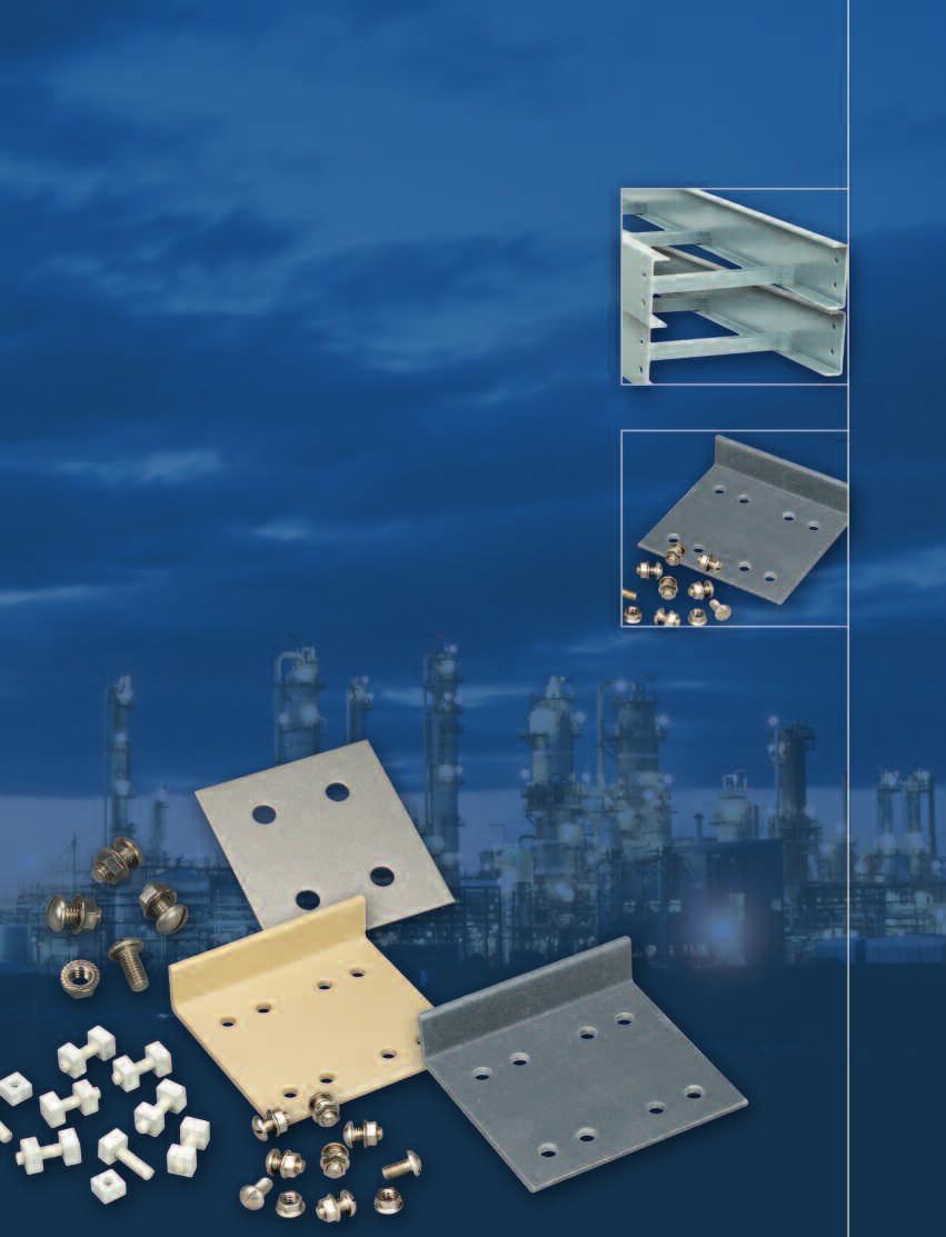
53 ACCESSORIES 6 splice plate c/w non-metallic hardware 6 splice plate c/w metallic hardware Stainless steel 4 splice plate c/w metallic hardware SPLICE PLATE SELECTION GUIDE NM - X SS ( ) SS6 CABLE TRAY SYSTEM Non-metallic ACCESSO- RY NUMBER MATERIAL SS - Stainless Steel FRP - Fiberglass P - Polyester V - Vinyl Ester # OF HOLES IN PLATE 4 8 TYPE/ANGLE 00 -Straight 04 - Step Down 01 -Slotted Straight 05 - Tray to Box 02 -Vertical Adjustable Angle 03 -Horizontal Angle Adjustable Angle TRAY SERI ES TYPE V - Vertical H - Horizontal HARDWARE SS6-316 Stainless Steel MO - Monel SB - Silicon Bronze FR - Fiberglass Example: NM-XSS4004SS6, Stainless steel 316, 4 holes supplied with stainless steel 316 hardware for a 4 deep straight section. Note: Splice plates shown on pages represent splices for 6 side rail height. Number of holes may vary with other side rail heights. STANDARD SPLICE PLATES Quantity required supplied with each tray section. Order only pairs of splice plates needed for field modifications. SS6 hardware supplied as standard - use SS6 suffix. Other hardware available, specify by hardware suffix. Hardware other than SS6 is considered special. Material Height Catalogue No. Stainless Steel 6" NM-XSS-8006* 4" NM-XSS-4004* 3" NM-XSS-4003* * Hardware suffix needed to complete part number ACCESSORIES EXPANSION SPLICE PLATE These plates allow for up to 1 expansion or contraction of tray system. For correct gap setting procedure, see page 10. Side Rail Material Height Catalogue No. Stainless Steel 316 (16 gauge) 6" NM-XSS-8016* 4 NM-XSS-4014* 3 NM-XSS-4013* * Hardware suffix needed to complete part number All splice plate hardware is 3/8. 51
54 ACCESSORIES NON-METALLIC CABLE TRAY & STRUT SYSTEMS HORIZONTAL ADJUSTABLE SPLICE PLATES These plates provide for changes in the horizontal direction that do not conform to standard fittings. Furnished in pairs Side Rail Material Height Catalogue No. Stainless Steel 316 (16 gauge) 6" NM-XSS-8036* 4" NM-XSS-4034* 3" NM-XSS-4033* * Hardware suffix needed to complete part number VERTICAL ADJUSTABLE SPLICE PLATES These plates provide for changes in elevation that do not conform to standard vertical fittings. Furnished in pairs Side Rail Material Height Catalogue No. Stainless Steel 316 (16 gauge) 6" NM-XSS-8026* 4" NM-XSS-4024* 3" NM-XSS-4023* * Hardware suffix needed to complete part number BLIND END PLATE TRAY TO BOX SPLICE PLATES This plate forms a closure for any tray that dead ends. Furnished as one plate. These plates are used to attach the end of a tray run to a distribution box or control center. Furnished in pairs Material Height Catalogue No. Stainless Steel 6" NM-XBE*1086W** 4" NM-XBE*1084W** 3" NM-XBE*1083W** * Material suffix: P=Polyester, V= Vinylester, S=Stainless Steel ** Hardware suffix needed to complete part number W = tray width Material Height Catalogue No. Stainless Steel 6" NM-XSS8056* 4" NM-XSS4054* 3" NM-XSS4053* * Hardware suffix needed to complete part number STEP DOWN PLATES These splice plates provide for changes in side rail heights. Furnished in pairs. Material Height Catalogue No. Stainless Steel 316 (16 gauge) 6" to 3" NM-XSS-8063* 6" to 4" NM-XSS-8064* 4" to 3" NM-XSS-4043* * Hardware suffix needed to complete part number All splice plate hardware is 3/8". Splice plates shown represent splices for 6 side rail height. Number of holes may vary with other side rail heights. 52
55 ACCESSORIES VERTICAL SPLICE PLATES 90 These splice plates provide for changes in elevation. Furnished in pairs. Side Rail Material Height Catalogue No. Stainless Steel 316 (16 gauge) 6" NM-XSS-8906V* 4" NM-XSS-4904V* 3" NM-XSS-4903V* * Hardware suffix needed to complete part number 45 These splice plates provide for changes in elevation. Furnished in pairs. Side Rail Material Height Catalogue No. Stainless Steel 316 (16 gauge) 6" NM-XSS-8456V* 4" NM-XSS-4454V* 3" NM-XSS-4453V* * Hardware suffix needed to complete part number 30 These splice plates provide for changes in elevation. Furnished in pairs. Side Rail Material Height Catalogue No. Stainless Steel 316 (16 gauge) 6" NM-XSS-8306V* 4" NM-XSS-4304V* 3" NM-XSS-4303V* HORIZONTAL SPLICE PLATES 90 These splice plates provide for changes in the horizontal direction. Furnished in pairs. * Hardware suffix needed to complete part number Side Rail Material Height Catalogue No. Stainless Steel 316 (16 gauge) 6" NM-XSS-8906H* 4" NM-XSS-4904H* 3" NM-XSS-4903H* ACCESSORIES 45 These splice plates provide for changes in the horizontal direction. Furnished in pairs. * Hardware suffix needed to complete part number Side Rail Material Height Catalogue No. Stainless Steel 316 (16 gauge) 6" NM-XSS-8456H* 4" NM-XSS-4454H* 3" NM-XSS-4453H* * Hardware suffix needed to complete part number 30 These splice plates provide for changes in the horizontal direction. Furnished in pairs. Side Rail Material Height Catalogue No. Stainless Steel 316 (16 gauge) 6" NM-XSS-8306H* 4" NM-XSS-4304H* 3" NM-XSS-4303H* * Hardware suffix needed to complete part number All splice plate hardware is 3/8". Splice plates shown represent splices for 6 side rail height. Number of holes may vary with other side rail heights. 53
56 ACCESSORIES LADDER DROP-OUT Specially-designed Ladder Drop-Outs provide a rounded surface with adequate radius to protect cable as it exists from the tray, preventing damage to insulation. Material Height Catalogue No. Polyester Resin Supplied with a 4 radius. W = tray width 6" to 36 NM-XF-1104-W BARRIERS Furnished with #10 x 3/4 self-tapping stainless steel screws Side Rail Material Height Catalogue No. Polyester Resin Vinyl Ester Resin 6" NM-BS06P-120 4" NM-BS04P-120 3" NM-BS03P-120 6" NM-BS06V-120 4" NM-BS04V-120 3" NM-BS03V-120 FLEXIBLE HORIZONTAL BARRIER KIT One Kit allows up to 38" radius position of the barrier. For larger than 38" radius barrier position, two kits are required. Kit Contents 1 pc - 72" Straight Barrier 4 pc - XF-9002 Barrier Strip Clip 8 pc - Thermoplastic Drive Rivet 4 Pc - #10 x 3/4" Stainless Steel Self-Tapping Screw Assembly required - directions included. Side Rail Loading Material Height Depth H Catalogue No. Polylester Resin Vinyl Ester Resin 6" 4-11/16 NM-BS06P-90HBFL 4" 2-11/16 NM-BS04P-90HBFL 3" 1-3/4 NM-BS03P-90HBFL 6" 4-11/16 NM-BS06V-90HBFL 4" 2-11/16 NM-BS04V-90HBFL 3" 1-3/4 NM-BS03V-90HBFL BARRIER MOUNTING ANGLE CLIPS WITH FASTENERS 1 pack contains 4 angle clips and fasteners. 2 thermoplastic drive rivets 1 #10 x 3/4" Stainless steel self-tapping screw. Material Polylester Resin Catalogue No. NM-PK-BAC CLAMP/GUIDE Combination hold down clamp and guide. Designed for 3/8" hardware - not included Furnished in pairs. Material Polyester Resin Catalogue No. NM-XFP
57 ACCESSORIES VERTICAL BARRIERS VO VI Barriers for vertical fitting. Please add angle (X) and radius ( ) to catalogue number. Furnished with #10 X 3/4 self-tapping stainless steel screws. Side Rail Material Height Catalogue No. Polyester Resin Vinyl Ester Resin VI = Inside vertical VO = Outside vertical 6" NM-BS06P(X)VI/VO( ) 4" NM-BS06P(X)VI/VO( ) 3" NM-BS06P(X)VI/VO( ) 6" NM-BS06V(X)VI/VO( ) 4" NM-BS06V(X)VI/VO( ) 3" NM-BS06V(X)VI/VO( ) SPRAY SEALANT Spray acrylic to reseal fiberglass after field modifications. Description 12 fl. oz. can Catalogue No. NM-CLEAR-1215 ACCESSORIES RESIN SEAL KIT To reseal fiberglass after field modifications. Vinyl Ester Resin Description 1/2 pint 1 pint Catalogue No. NM-RSK-05 NM-RSK-10 Kit Contents Resin Catalyst Stir stick and applicator 55

 COVERS FOR FITTINGS COVERS SELECTION GUIDE NM - FC P 12 HB 90 24 Material thickness: 1/8\" Standard mounting hardware: (10 each) #10 x 1/2\" stainless, self-tapping screws provided with each section")
58 ACCESSORIES NON-METALLIC CABLE TRAY & STRUT SYSTEMS COVERS FOR STRAIGHT SECTIONS Material thickness: 1/8" Standard cover length: 120" (10') Standard mounting hardware: (10 each) #10 x 1/2" stainless, self-tapping screws provided with each section NM - FC P NON- METALLIC COVERS SELECTION GUIDE COVER TYPE FC = Flat PC = Peaked MATERIAL P = Polyester V = Vinyl Ester TRAY WIDTH 6 to 36 Note : Peaked covers available for straight sections only. LENGTH 120 (10 ft.) COVERS FOR FITTINGS COVERS SELECTION GUIDE NM - FC P 12 HB Material thickness: 1/8" Standard mounting hardware: (10 each) #10 x 1/2" stainless, self-tapping screws provided with each section NON- METAL- LIC TYPE OF COVER FC = Flat MATERIAL P = Polyester V = Vinyl Ester WIDTH 6 to 36 FITTING DESIGNA- TION HB IV/OV HT HX ANGL E RADIU S Note : Peaked covers not available. Other fitting covers are available. Please consult your sales office. HEAVY DUTY COVER CLAMP Recommended for outdoor service. Heavy duty cover clamp available for flat covers only. Available in both Polyester and Vinyl Ester Resin. Side Rail Material Height Catalogue No. Polyester Resin Vinyl Ester Resin * W = tray width 6" NM-XWC-P-W* " NM-XWC-P-W* " NM-XWC-P-W* " NM-XWC-C-W* " NM-XWC-C-W* " NM-XWC-C-W*-9034 THERMOPLASTIC DRIVE RIVET Shipped in packages of 25 pcs. Material Thermoplastic Catalogue No. TPDR Raised cover clamps available. Plesase consult your sales offices. 56
59 section 5 CABLE CHANNEL
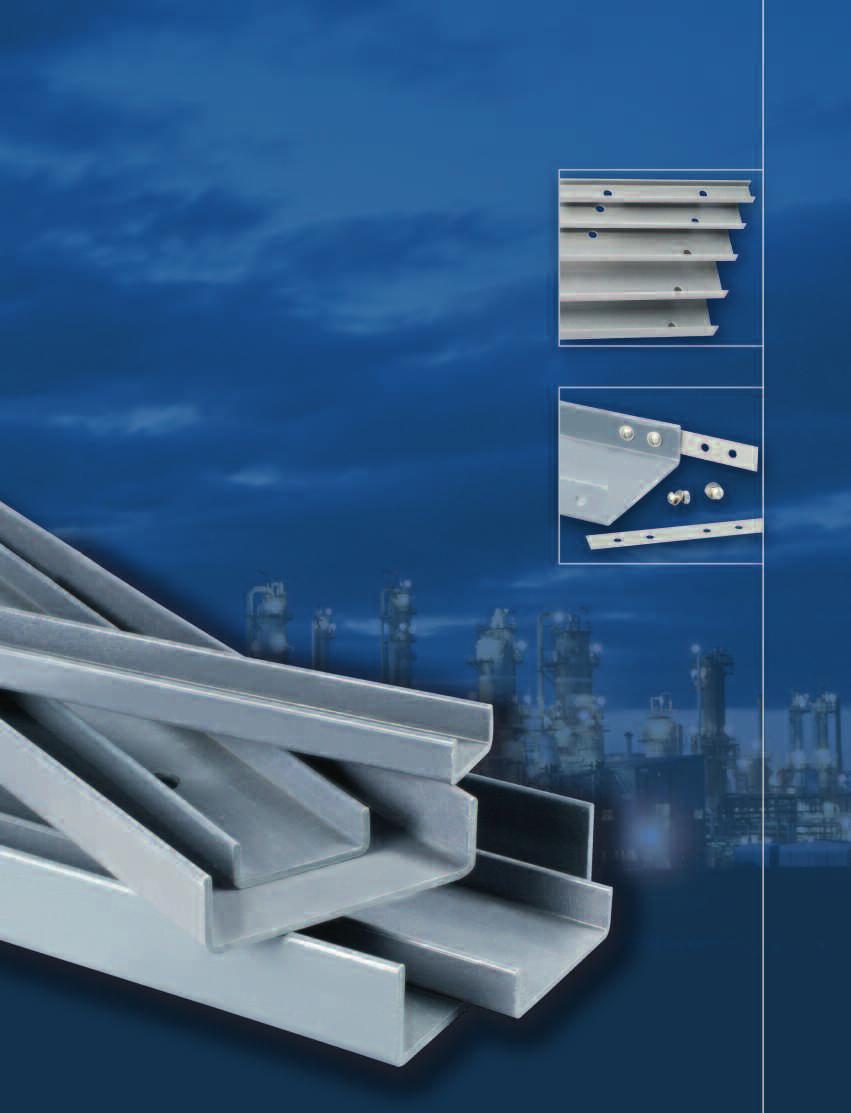
60 58

61 FIBERGLASS CABLE CHANNEL Thomas & Betts offers non-metallic cable channel in solid or ventilated straight sections. Horizontal and vertical solid bottom fittings are also available to complete your system layout. STRAIGHT SECTION CATALOGUE SELECTOR NM - FCC V P CABLE TRAY SYSTEM NM = Non-metallic SERIES Fiberglass Cable Channel BOTTOM TYPE V = Ventilated N = Nonventilated MATERIAL P = Polyester Resin V = Vinyl Ester Resin WIDTH 02 = 2 03 = 3 04 = 4 06 = 6 08 = 8 LENGTH 120 = 120 (10 ft) 240 = 240 (20 ft) Example: NM-FCCVP for Polyester Resin Cable Channel, 4 wide ventilated bottom, 120 (10 ft) length SPECIFICATIONS VENTILATED NONVENTILATED Width Height Length Width Height Length in. in. ft. Polyester Vinyl Ester in. in. ft. Polyester Vinyl Ester NM-FCCVP NM-FCCVV NM-FCCNP NM-FCCNV NM-FCCVP NM-FCCVV NM-FCCNP NM-FCCNV NM-FCCVP NM-FCCVV NM-FCCNP NM-FCCNV NM-FCCVP NM-FCCVV NM-FCCNP NM-FCCNV /8 10 NM-FCCVP NM-FCCVV /8 10 NM-FCCNP NM-FCCNV /8 20 NM-FCCVP NM-FCCVV /8 20 NM-FCCNP NM-FCCNV /8 10 NM-FCCVP NM-FCCVV /8 10 NM-FCCNP NM-FCCNV /8 20 NM-FCCVP NM-FCCVV /8 20 NM-FCCNP NM-FCCNV /16 10 NM-FCCVP NM-FCCVV /16 10 NM-FCCNP NM-FCCNV /16 20 NM-FCCVP NM-FCCVV /16 20 NM-FCCNP NM-FCCNV Splice plates NOT included. See page 60 for type of splice plates available. Covers are available. Please consult your sales office. 8 CABLE CHANNEL 59

62 CABLE CHANNEL FITTINGS HORIZONTAL HB Horizontal Bend Angle Width Catalogue No " NM-FCCNP-03-90HB 12 4" NM-FCCNP-04-90HB 12 6" NM-FCCNP-06-90HB 12 8" NM-FCCNP-08-90HB 12 3" NM-FCCNP-03-45HB 12 4" NM-FCCNP-04-45HB 12 6" NM-FCCNP-06-45HB 12 8" NM-FCCNP-08-45HB 12 One pair of splice plates with SS6 hardware included. For vinyl ester resin, use V instead of P in part number. Example: FCCNV-04-90HB12 VERTICAL VO Vertical VI Angle Width Catalogue No " NM-FCCNP-03-90V* 12 4" NM-FCCNP-04-90V* 12 6" NM-FCCNP-06-90V* 12 8" NM-FCCNP-08-90V* 12 3" NM-FCCNP-03-45V* 12 4" NM-FCCNP-04-45V* 12 6" NM-FCCNP-06-45V* 12 8" NM-FCCNP-08-45V* 12 One pair of splice plates with SS6 hardware included. For vinyl ester resin, use V instead of P in part number. Example: FCCNV-04-90VI12 HORIZONTAL TEES HT Width in. Catalogue No. 3 NM-FCCNP-03-HT12 4 NM-FCCNP-04-HT12 6 NM-FCCNP-06-HT12 8 NM-FCCNP-08-HT12 Two pairs of splice plates included. For vinyl ester resin, use V instead of P in part number. Example: FCCNV-04-HT12 HORIZONTAL CROSSES HX Width in. Catalogue No. 3 NM-FCCNP-03-HX12 4 NM-FCCNP-04-HX12 6 NM-FCCNP-06-HX12 8 NM-FCCNP-08-HX12 Three pairs of splice plates included. For vinyl ester resin, use V instead of P in part number. Example: FCCNV-04-HX12 Covers available. Please contact your sales office. 60
63 CABLE CHANNEL SPLICE PLATES Standard hardware is 1/4 Stainless Steel 316. STANDARD SPLICE PLATE Material Stainless Steel Polyester Resin Vinyl Ester Resin Cat. No. NM-XSS-1001-SS6 NM-XFP-1001-SS6 NM-XFV-1001-SS6 Supplied in pairs EXPANSION SPLICE PLATE Material Stainless Steel Polyester Resin Vinyl Ester Resin Cat. No. NM-XSS-1011-SS6 NM-XFP-1011-SS6 NM-XFV-1011-SS6 Supplied in pairs HORIZONTAL 90º SPLICE PLATES Material Stainless Steel Polyester Resin Vinyl Ester Resin Cat. No. NM-XSS-190IH-SS6 NM-XFP-190IH-SS6 NM-XFV-190IH-SS6 Supplied in pairs HORIZONTAL 45º SPLICE PLATES Material Stainless Steel Polyester Resin Vinyl Ester Resin Cat. No. NM-XSS-145IH-SS6 NM-XFP-145IH-SS6 NM-XFV-145IH-SS6 Supplied in pairs HORIZONTAL 30º SPLICE PLATES Material Stainless Steel Polyester Resin Vinyl Ester Resin Cat. No. NM-XSS-130IH-SS6 NM-XFP-130IH-SS6 NM-XFV-130IH-SS6 Supplied in pairs CABLE CHANNEL 61
64 CABLE CHANNEL SPLICE PLATES VERTICAL 90º SPLICE PLATES Material Stainless Steel Polyester Resin Vinyl Ester Resin Cat. No. NM-XSS-190IV-SS6 NM-XFP-190IV-SS6 NM-XFV-190IV-SS6 Supplied in pairs VERTICAL 45º SPLICE PLATES Material Stainless Steel Polyester Resin Vinyl Ester Resin Cat. No. NM-XSS-145IV-SS6 NM-XFP-145IV-SS6 NM-XFV-145IV-SS6 Supplied in pairs VERTICAL 30º SPLICE PLATES Material Stainless Steel Polyester Resin Vinyl Ester Resin Cat. No. NM-XSS-130IV-SS6 NM-XFP-130IV-SS6 NM-XFV-130IV-SS6 Supplied in pairs 62
65 section 6 NON-METALLIC STRUT SYSTEMS
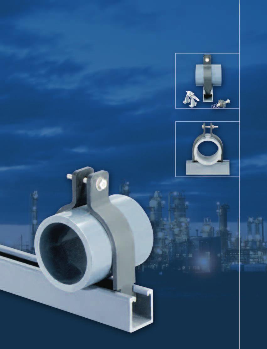
66 64

67 NON-METALLIC STRUT SYSTEMS Thomas & Betts is proud to present its new line of Non-metallic Struts and Accessories. You ll find a complete selection of non-metallic accessories, fasteners, hangers, pipe clamps and channels. Most Thomas & Betts Strut Products are available in a choice of resins either vinyl ester or polyester. Our design and engineering staff is ready to help you select the material that best suits your needs. STRUT STRAIGHT SECTION CATALOGUE SELECTOR NM - SS 100 ( ) ( ) - 20 STRUT SYSTEM NM = Non-metallic TYPE OF SYSTEM SS = Strut system SIZE 100 = = 1-5/8 DOUBLE D = double Blank = single HOLES/SLOTS/ INSERT H = holes I = insert S = slots LENGTH 120 = 10 ft 240 = 20 ft Example: NM-SS , 1 single strut, 120 inches (10 ft). Note: Stocked in 120 inches (10 ft) and 240 inches (20 ft). NON-METALLIC STRUT SYSTEMS 65
-100 NM-SS(*)-158 Vinyl Ester NM-SSV-100-(L) Beige 0.47 0.70 NM-SSV-158-(L) Beige 0.63 0.94 (L) Add desired length 120 (10 ft) or 240 (20 ft). Cut-to-length channel also available.")
 Grey 1.17 1.75 Vinyl Ester NM-SSV-100-D-(L) Beige 0.86 1.28 NM-SSV-158-D-(L) Beige 1.17 1.75 (L) Add desired length 120 (10 ft) or 240 (20 ft).")
68 CHANNELS, COMBINATIONS & HOLE PATTERN SOLID - SINGLE STRUT Weight Material/Resin Catalogue No. Color lb. / ft. kg / m Polyester NM-SSP-100-(L) Grey NM-SSP-158-(L) Grey NM-SS(*)-100 NM-SS(*)-158 Vinyl Ester NM-SSV-100-(L) Beige NM-SSV-158-(L) Beige (L) Add desired length 120 (10 ft) or 240 (20 ft). Cut-to-length channel also available. Contact your sales office for more information. *Add P - for polyester or V - for vinyl ester SOLID - BACK TO BACK Weight Material/Resin Catalogue No. Color lb. / ft. kg / m NM-SSP-100-D-(L) Grey Polyester NM-SSP-158-D-(L) Grey Vinyl Ester NM-SSV-100-D-(L) Beige NM-SSV-158-D-(L) Beige (L) Add desired length 120 (10 ft) or 240 (20 ft). Cut-to-length channel also available. Contact your sales office for more information. NM-SS(*)-100-D NM-SS(*)-158-D *Add P - for polyester or V - for vinyl ester PUNCHED Holes - 9/16 holes X 1-7/8 on center Weight Material/Resin Catalogue No. Color lb. / ft. kg / m NM-SSP-100-H-(L) Grey Polyester NM-SSP-158-H-(L) Grey NM-SSV-100-H-(L) Beige Vinyl Ester NM-SSV-158-H-(L) Beige (L) Add desired length 120 (10 ft) or 240 (20 ft). Cut-to-length channel also available. Contact your sales office for more information. 66
69 CHANNELS, COMBINATIONS & HOLE PATTERN SLOTTED Slots - 9/16 X 7/8 on 2 centers Weight Material/Resin Catalogue No. Color lb. / ft. kg / m Polyester Vinyl Ester NM-SSP-100-S-(L) NM-SSV-100-S-(L) Beige Grey NM-SSP-158-S-(L) NM-SSV-158-S-(L) Beige Grey (L) Add desired length 120 (10 ft) or 240 (20 ft). Cut-to-length channel also available. Contact your sales office for more information. CONCRETE INSERT Weight Material/Resin Catalogue No. Color lb. / ft. kg / m Polyester Vinyl Ester NM-SSP-158-I-(L) Grey NM-SSV-158-I-(L) Beige (L) Add desired length 120 (10 ft) or 240 (20 ft). Cut-to-length channel also available. Contact your sales office for more information. CLOSURE STRIP Closure strip fits all 1-5/8 wide strut regardless of depth. Weight Material/Resin Catalogue No. Color lb. / ft. kg / m NM-SSCS Grey TBA TBA Polyester Note : Not available in vinyl ester. Only stocked in 120 or 10 ft lengths. Contact your sales office for more information. NON-METALLIC STRUT SYSTEMS 67


 wide and")


70 NON-METALLIC STRUT FITTINGS AND BRACKETS NM-SFP-1S7 NM-SFP-1S9 NM-SFP-2S NM-SFP-3S NM-SFP-4S NM-SFP-5S NM-SFP-3HL NM-SFP-4HL NM-SFP-4HT NM-SFP-5HX NM-SFP-3HCG NM-SFP-4HCG NM-SFP-5HCG NM-SFP-3HTG NM-SFP-4HTG NM-SFP-5HTG All fittings are 1-5/8 (41) wide and 1/4 (6) thick unless specified otherwise. All holes are 13/32 (10) diameter unless specified otherwise. 68


")


71 NON-METALLIC STRUT FITTINGS AND BRACKETS NM-SFP-6HTG NM-SFP-7HXG NM-SFP-3VL NM-SFP-4VL NM-SFP-4VLD NM-SFP-4VGL NM-SFP-4VGR NM-SFP-4VTG Window Clamp Double Base Single Base NM-SFP-3CB NM-SWC-158 NM-SSV-DBASE NM-SSV-SBASE Channel Spacer (for 3/8 rod) NON-METALLIC STRUT SYSTEMS NM-SCSP-158 All fittings are 1-5/8 (41) wide and 1/4 (6) thick unless specified otherwise. All holes are 13/32 (10) diameter unless specified otherwise. 69
72 NON-METALLIC THREADED HARWARE NON-METALLIC CABLE TRAY & STRUT SYSTEMS HEX HEAD BOLT Thread Bolt lgth Design Load Max Torque Weight / C Size Catalogue No. in. lb. N in-lbs N-m lb. g 5/16-18 NM-F /16 x /16-18 NM-F /16 x 1-1/ /8-16 NM-F /8 x /8-16 NM-F /8 x 1-1/ /8-16 NM-F /8 x 2-1/ /2-13 NM-F /2 x /2-13 NM-F /2 x 1-1/ /2-13 NM-F /2 x 2-1/ Safety Factor of 3 on Design Load. HEX NUT Height Weight / C Thread Size Catalogue No. in. mm lb. g 3/8-16 NM-F38HN 21/ /2-13 NM-F12HN 7/ /8-11 NM-F58HN 35/ Note: 3/4 and 1 sizes are available. ALL-THREAD ROD Design Load Max Torque Weight / C Thread Size Catalogue No. lb. N in-lbs N-m lb. g 3/8-16 NM-F38AT /2-13 NM-F12AT /8-11 NM-F58AT Safety Factor of 3 on Design Load. Note: 3/4 and 1 sizes are available. Standart lengths are 4 and 8. Example: NM-F38AT-4. ALL-THREAD ROD HEX NUT Height Weight / C Thread Size Catalogue No. in. mm lb. g 3/8-16 NM-F38ATHN 3/ /2-13 NM-F12ATHN 7/ ROD COUPLER Weight / C Thread Size Catalogue No. lb. g 3/8-16 NM-FRC /2-13 NM-FRC /8-11 NM-FRC /4 and 1 sizes are available. 70


73 NON-METALLIC PIPE HANGERS, BRACKETS & BEAM CLAMPS CLEVIS HANGERS Nominal Pipe Size Maximum O.D. Range Hanger Rod Design Load in. mm Cat. No. in. mm Size lb. N-m 2 50 NM-SCH /2 63 1/ /2 65 NM-SCH /4 82 1/ NM-SCH /8 98 1/ NM-SCH / NM-SCH / NM-SCH / NM-SCH / / NM-SCH / / Safety Factor of 3 on Design Loads at 120 F (49 C). Insulation may be required at high temperatures. Order hanger rods and nuts separately. SUPPORT BRACKETS SB 1 SB 2 Dimension A Design Load Cat. No.* in. mm lb. N NM-SB1-06P NM-SB1-09P NM-SB1-12P NM-SB1-18P NM-SB1-24P NM-SB2-24P NM-SB2-30P NM-SB2-36P *Substitute V for P when Vinyl Ester Resin is needed. Design loads based on uniform loading with a Safety Factor of 3. BEAM CLAMPS Design Load Description Cat. No. lb. / ft. kg / m Beam Clamp NM-SBC Beam Clamp w/retainer clip NM-SBC-RC Safety Factor of 3 on Design Load. NON-METALLIC STRUT SYSTEMS 71

74 NON-METALLIC THREADED HARDWARE & SEALANT H U-BOLT Load A Pipe Load B Nominal H Design Design Max. Weight Pipe Size Height Catalogue Load A Load B Torque / C in. mm in. No. lb. N lb. N in.-lb. N-m lb. g 1/ NM-FUB / NM-FUB NM-FUB / NM-FUB / NM-FUB NM-FUB / NM-FUB NM-FUB / NM-FUB NM-FUB Safety Factor of 3 on Design Load. CHANNEL NUT Cat. No. Cat. No. Pull-Out Slip Resistance Max. Torque Weight / C Thread w/spring w/o spring lb. N lb. N in.-lb. N-m lb. g 3/8 16 NM-FCN38 FCN38WO /2 13 NM-FCN12 FCN12WO Safety Factor of 3 on Design Load. Note: 1/4 and 5/16 sizes are available. FLAT WASHER Hole Size Weight / C in. Cat. No. lb. g 3/8 NM-F38W /2 NM-F12W /8 NM-F58W /4 NM-F34W NM-F100W SPRAY SEALANT Spray acrylic to reseal fiberglass after field modifications. Description 12 fl. oz. can Catalogue No. NM-CLEAR-1215 BRUSH-ON RESIN SEAL KIT Description Catalogue No. To reseal fiberglass after field modifications. Vinyl Ester Resin Kit Contents Resin Catalyst Stir stick and applicator 1/2 pint 1 pint NM-RSK-05 NM-RSK-10 72

75 PIPE CLAMPS ADJUSTABLE PIPE CLAMP Nominal Pipe Size Pipe O.D. Range Design Load Max. Torque in. mm Cat. No. in. mm lb. N in.- lb. N-m 1/2 to 3/ NM-SAPC to to to 1-1/ NM-SAPC to to /2 to 2-1/ NM-SAPC to to /2 to 3-1/ NM-SAPC to to Safety Factor of 3 on Design Load. Not recommended for vertical installation without additional supports RIGID PIIPE CLAMP Nominal Pipe Size Design Load Max. Torque in. mm Cat. No. lb. N in.-lb. N-m 1/2 15 NM-SRPC /4 20 NM-SRPC NM-SRPC /4 32 NM-SRPC /2 40 NM-SRPC NM-SRPC /2 65 NM-SRPC NM-SRPC /2 90 NM-SRPC NM-SRPC Safety Factor of 3 on Design Load. Not recommended for vertical installation without additional supports CONDUIT SWIVEL CLAMP Rigid pipe clamp (sold separately) Conduit Catalogue No. NM-SCSC-(CTD) Cable Tray Designation (CTD) required (Ex. 6CP Series designates 6 deep polyester resin). Pipe Clamps are a separate order item. Cable tray side rail NON-METALLIC STRUT SYSTEMS 73
76 NON-METALLIC STRUT LOAD CHARTS NON-METALLIC CABLE TRAY & STRUT SYSTEMS LOADING INFORMATION Beam Loads: The charts below list the total allowable uniform load for various simple spans based on a minimum safety factor of 2. If the load is concentrated at center span, multiply the load by 0.5 and the corresponding deflection by 0.8. BEAM LOADING DATA FOR GLASS REINFORCED POLYESTER RESIN Deflection Maximum at Maximum Allowable Deflection = Allowable Allowable Beam Catalogue Beam Load Beam Load 1/240 Span 1/360 Span Span No. lb. N in. mm lb. N lb. N 12 (305) 24 (609) 36 (914) NM-SSP NM-SSP-100-D NM-SSP NM-SSP-158-D NM-SSPP NM-SSP-100-D NM-SSP NM-SSP-158-D NM-SSP NM-SSP-100-D NM-SSP NM-SSP-158-D BEAM LOADING DATA FOR GLASS REINFORCED VINYL ESTER RESIN Deflection Maximum at Maximum Allowable Deflection = Allowable Allowable Beam Catalogue Beam Load Beam Load 1/240 Span 1/360 Span Span No. lb. N in. mm lb. N lb. N 12 (305) 24 (609) 36 (914) NM-SSV NM-SSV-100-D NM-SSV NM-SSV-158-D NM-SSV NM-SSV-100-D NM-SSV NM-SSV-158-D NM-SSV NM-SSV-100-D NM-SSV NM-SSV-158-D Note: Dimensions shown as metric are in millimeters, unless otherwise specified. RECOMMENDED GUIDELINE Published design loads are based on usage at 70 F (21 C) and must be reduced for continuous exposure to higher temperatures. Refer to the chart at right for high temperature applications. Design Load Temperature Multiplier 75 F (24 C) 100% 100 F (38 C) 90% 125 F (52 C) 78% 150 F (66 C) 68% 175 F (79 C) 60% 200 F (93 C) 52% 74
77 NOTES 75
78 NOTES 76
79 NOTES 77
80 NOTES 78


 than other")


81 OTHER PRODUCTS For more information on the wide variety of other non-metallic products available, please contact your nearest T&B sales office. MOLDED GRATING GatorGrate molded fiberglass grating, with high bidirectional strength, is both fire-retardant and corrosion-resistant and has an integral antislip top surface. HAND RAILS GatorGrate pultruded FRP hand rails guard against slips and falls. Built to OSHA standards. Standard color is safety yellow. PULTRUDED GRATING GatorDeck pultruded fiberglass grating offers superior load-carrying ability over longer spans, at a competitive price. It is both fire retardent and corrosion resistant. LADDERS GatorGrate FRP safety ladders and caged ladders guard against slips and falls. Built for positive traction and easy gripping, they will withstand rugged use in tough environments. MOLDED STAIR TREADS GatorGrate molded stair treads not only offer the same rugged performance and corrosion-resistance found in GatorGrate, but also carry more load (tread for tread) than other molded stair treads. FLOOR PLATE GatorPlate floor plate is ideal for fixing slippery spots or in large slippery areas. The antislip surface helps reduce slips and falls even when hazardous liquids are present. PULTRUDED STAIR TREADS GatorDeck pultruded stair treads are available in two resin systems as well as six span widths and in both yellow and gray colors. COVERED GRATING GatorGrate covered grating combines floor plate with molded grating for added strength and durability. The entire structure is molded into an integral, corrosion-resistant, antislip panel. STRUCTURAL SHAPES Structural shapes are available in standard configurations including angles, I-beams, wide flange beams, channels, bars, round and square tubes. Custom shapes are available, too!
Dynaform Fiberglass Structural Shapes. Design Guide. High Performance Composite Solutions. Corrosion Resistant. Fire Retardant.
 Design Guide Dynaform Fiberglass Structural Shapes Corrosion Resistant Fire Retardant Low Maintenance Light Weight Long Service Life High Performance Composite Solutions Q U A L I T Y ISO 9001-2000 C E
NO: AC.2006.CT.01 شرکت کامپوزیت آسیاآسیا(سهامی تولیدکننده انواع قطعات کامپوزیتی گریتینگ و سینی کابل)
") NO: AC.2006.CT.01 خاص) شرکت کامپوزیت آسیاآسیا(سهامی تولیدکننده انواع قطعات کامپوزیتی گریتینگ و سینی کابل) (پروفیل FRP SPECIFICATIONS OF PULTRUDED LADDER-TYPE CABLE TRAYS E- mail:info@asiacomposite.comww
NO: AC.2006.CT.01 خاص) شرکت کامپوزیت آسیاآسیا(سهامی تولیدکننده انواع قطعات کامپوزیتی گریتینگ و سینی کابل) (پروفیل FRP SPECIFICATIONS OF PULTRUDED LADDER-TYPE CABLE TRAYS E- mail:info@asiacomposite.comww
We offer two fire retardant (FR) resins for strut systems: polyester and vinyl ester. Both resins are ideal for corrosive environments.
 resins for strut systems: polyester and vinyl ester. Both resins are ideal for corrosive environments.") Materials We offer two fire retardant (FR) resins for strut systems: polyester and vinyl ester. Both resins are ideal for corrosive environments. While polyester is sufficient for most uses, vinyl ester
Materials We offer two fire retardant (FR) resins for strut systems: polyester and vinyl ester. Both resins are ideal for corrosive environments. While polyester is sufficient for most uses, vinyl ester
Fiberglass Cable Ladder
 Cable Ladder GRP-1 Cable Ladder GRP-2 Cable Ladder Corrosion Guide The information shown in this corrosion guide is based on full immersion laboratory tests and data generated from resin manufacturer's
Fiberglass Cable Ladder & Channel
 Cable Ladder & Channel 168 Cable Ladder & Channel 169 Technical Data Corrosion Guide The information shown in this corrosion guide is based on full immersion laboratory tests and data generated from resin
Fibreglass Reinforced Plastic
 Fibreglass Reinforced Plastic Grating / Structural / Hand Rail Systems Won t Rust - Stronger than Steel ISO 2001 Certified Grating FRP Handrail Systems Certified to Australian Standards AS-1657-2013 We
DURA SLAB PULTRUDED TECHNICAL SPECIFICATIONS January 2014
 DURA SLAB PULTRUDED TECHNICAL SPECIFICATIONS January 2014 Definition Glass-reinforced plastic (GRP) is a composite material made of a thermosetting plastic resin reinforced by fine fibres of glass along
FRP RADIAL FUME EXHAUSTERS/ PRESSURE BLOWERS THE NEW YORK BLOWER COMPANY
 FRP BULLETIN 58 DECEMBER, 2005 RADIAL FUME EXHAUSTERS/ PRESSURE BLOWERS Fiberglass-reinforced-plastic fans for handling corrosive gas streams in a wide variety of process applications... FRP RADIAL FUME
Metallic Systems TYPE SPTC
 CONDUIT 27/01/2009 Technical Data Sheet Page No. 1 Applications Hospitals External Safety Critical Area Fittings IP54 SPB Fittings type A & B Characteristics Very High UV Resistance High Flexibility Medium
Application Data Sheet. Chemical Compatibility Chart. IND-AS EN-01 (May, 2014) Metals Plastics Seals KEY. Good. Fair. Ethylene Propylene.
 Metals Plastics Seals KEY. Good. Fair. Ethylene Propylene.") Chemical Compatibility Chart 6 Stainless Acetic Acid Acetone Acetylene Acidic Mine Water Acrylonitrile Ammonium Chloride Ammonium Hydroxide Ammonium Sulfate Ammonium Thio-Sulfate Anhydrous Ammonia Anhydrous
Chemical Compatibility Chart 6 Stainless Acetic Acid Acetone Acetylene Acidic Mine Water Acrylonitrile Ammonium Chloride Ammonium Hydroxide Ammonium Sulfate Ammonium Thio-Sulfate Anhydrous Ammonia Anhydrous
Selection of DODGE E-Z KLEEN Polymer and Stainless Steel Housed Ball Bearings. P = (X x F R ) + (Y x F A ) F A C o
 + (Y x F A ) F A C o") Selection of DODGE and Stainless Steel Housed Ball Bearings DODGE ball bearings are primarily designed for radial loading. However, they have the capacity to carry thrust loads and combined radial/thrust
Selection of DODGE and Stainless Steel Housed Ball Bearings DODGE ball bearings are primarily designed for radial loading. However, they have the capacity to carry thrust loads and combined radial/thrust
INTRODUCING A NEW LINE OF FRP PRODUCTS
 BEING SMART IS GOOD. BEING FIRST IS GOOD. BEING BOTH IS BETTER. INTRODUCING A NEW LINE OF FRP PRODUCTS CABLE LADDERS AND TRAYS Type FOE and FTE OGLAEND SYSTEM The perfect partner for your next project!
Swivel Joints Flexmaster Joints Part Number NH NH NH NH NH NK NK
 FLUID CONVEYING PRODUCTS Section Pages Hose 15-67 Fittings 68-180 Adapters and Tube Fittings 181-228 Description Page Features 246, 247 Technical Data 248, 253 Gasket Selector Chart 249 How to Order 250
Section 3 - Chemical/Environmental Resistance Part 1 - XR-5 Fluid Resistance Guidelines
 Section 3 - Chemical/Environmental Resistance Part 1 - XR-5 Fluid Resistance Guidelines The data below is the result of laboratory tests and is intended to serve only as a guide. No performance warranty
How to Use the Chemical Compatibility Chart. Vials and Closures >> Chemical Compatibility Chart
 How to Use the Chemical Compatibility Chart The following chart contains information regarding the expected effects of 7 day direct solvent exposure on materials used for production of vials, caps and
Hose and Fitting Edition
 and Fitting Edition www.dnpamericas.com Phone: 281-388-0253 Fax: 281-388-1902 1 Table of Contents Determining Size 3 Selection Table 4 1SC, 100R2AT 5 100R16, 100R17 6 Jackhose, 2SN 7 4SP, 4SH 8 100R13,
Fiberglass Centrifugal Exhausters. Series 82 Series 83 Series 87 Series 88 HARTZELL. Hartzell Fan, Inc., Piqua, Ohio
 Fiberglass Centrifugal Exhausters Series 82 Series 83 Series 87 Series 88 BUILT WITH HONOR HARTZELL FAN, INC PIQUA, OHIO USA HARTZELL Hartzell, Inc., Piqua, Ohio 45356 November 2007 Index Hartzell Model
High pressure industrial ball valves
 High pressure industrial ball valves High pressure industrial ball valves Applications Legris high pressure ball valves are suited for a wide range of industrial applications. They are designed both for
Physical properties of PET resins. 1. Intrinsic Viscosity (IV)
") Physical properties of PET resins 1. Intrinsic Viscosity (IV) Intrinsic viscosity (IV) is a measure of polymer molecular weight, which in turn is a measure of the mechanical strength capability of the
Physical properties of PET resins 1. Intrinsic Viscosity (IV) Intrinsic viscosity (IV) is a measure of polymer molecular weight, which in turn is a measure of the mechanical strength capability of the
Series 3 & 4 Stainless Steel - Accessories
 - Accessories Splice Plates Standard 8-hole pattern for all steel splice plates. One pair including hardware provided with straight section. (Expansion splice quantity subtracted) Boxed in pairs with hardware.
Small on price, big on boot
 018 VOLUME 1 FEATURES KEY Toe Cap High Heat Non Conductive Female Male Leather Chemical Body International Organization for Standardisation Body PU - Polyurethane RECOMMENDED INDUSTRY USE* General Smelting/
SUPERLIT GRP PIPE & FITTINGS AS AS GLASS REINFORCED POLYESTER (GRP) PIPELINE SYSTEM VERSION 1.0
 PIPELINE SYSTEM VERSION 1.0") SUPERLIT GRP PIPE & FITTINGS AS3571.1 AS3571.2 GLASS REINFORCED POLYESTER (GRP) PIPELINE SYSTEM VERSION 1.0 The products shown form part of our continuous improvement program and as such the product designs,
SUPERLIT GRP PIPE & FITTINGS AS3571.1 AS3571.2 GLASS REINFORCED POLYESTER (GRP) PIPELINE SYSTEM VERSION 1.0 The products shown form part of our continuous improvement program and as such the product designs,
Polyline Polycarbonate Enclosures
 TM Polyline Polycarbonate Enclosures Authorized Distributor: From Allied Moulded Products, Inc. Experts in manufacturing nonmetallic enclosures for industrial applications WESCHLER INSTRUMENTS 800-903-9870
FR PVC COATED RAINWEAR
 FR COATED RAINWEAR INDUSTRY/FORESTRY/RAINWEAR All fabrics are tested and certified in accordance with en 343; the european standard for waterproof clothing. Extreme weather protection - EN 343 Protection
The Industrial Choice. Model TFBD. Model FBD FIBERGLASS AXIAL FLOW FANS. Model FDP / FRV / FBD / TFBD / VTFBD
 The Industrial Choice. Model TFBD Model FBD FIBERGLASS AXIAL FLOW S Model FDP / FRV / FBD / TFBD / VTFBD CATALOG 85 October 207 Fiberglass Axial Flow Fans Models FDP FRV FBD TFBD VTFBD Medium Pressure
Series 2, 3, 4 Steel Cable Ladder Steel Cable Ladder, Series 2, 3, 4 & 5
 Cable Ladder with Slotted Rung (shown with alternating slot orientation) Cable Ladder with Slotted Rung (shown with continuous slot down - also available with continuous slot up) HDS-1 Steel Cable Ladder,
Series 3 & 4 Stainless Steel - Accessories
 Splice Plates Standard 8-hole pattern for all stainless steel splice plates. One pair including hardware provided with straight section. Boxed in pairs with hardware. Expansion Splice Plates Expansion
Series 1 Steel - Straight Sections
 Series 1 Steel - Straight Sections Series 1 Steel H-1 B-Line series Cable Tray Systems Series 1 Steel - ccessories & Fittings Series 1 Steel How The Service dvisor Works We know that your time is important!
TANK LINING RESISTANCE GUIDE I-19
 INTRODUCTION Wattyl s Tank Lining Resistance Guide provides a list of chemicals and their suitability in contact with Epinamel TL710, Galvit ES600 and Galvit ES510. GUIDE TO DATA R Recommended cargo R,
Issue One. Chemical Compatibility Guide
 Issue One Chemical Compatibility Guide Chemical Compatibility Guide Fluolion 200, 700, 800, 900 modified PTFE sheet gasket materials The following information is issued as a guide only. All media are taken
Ducting & Ventilation Components
 Ducting & Ventilation Components 111 Powell Road Independence, MO 64056 visit www.hemcocorp.com Phone: 816-796-2900 Fax : 816-796-3333 E-Mail : info@hemcocorp.com Exhaust Blowers are constructed of chemical
T&B Cable Tray. Nonmetallic Strut Systems NM -SS P- 100 ( ) ( ) Channels
 ( ) Channels") Channels Thomas & Betts is proud to present its new line of nonmetallic struts and accessoires. You ll find a complete selection of nonmetallic accessoires, fasteners, hangers, pipe clamps and channels.
Channels Thomas & Betts is proud to present its new line of nonmetallic struts and accessoires. You ll find a complete selection of nonmetallic accessoires, fasteners, hangers, pipe clamps and channels.
CONNECTION BULLETIN. Vogt Valves. Experience In Motion. Zero Leakage Forged Steel Check Valves Class 800. FCD VVABR /04 (Replaces CB-03)
") CONNECTION BULLETIN Vogt Valves Zero Leakage Forged Steel Check Valves Class 800 FCD VVABR1003-00 10/04 (Replaces CB-03) Experience In Motion Zero Leakage, Forged Steel Check Valves: Class 800 Vogt Series
CONNECTION BULLETIN Vogt Valves Zero Leakage Forged Steel Check Valves Class 800 FCD VVABR1003-00 10/04 (Replaces CB-03) Experience In Motion Zero Leakage, Forged Steel Check Valves: Class 800 Vogt Series
SETUP, OPERATING AND MAINTENANCE INSTRUCTIONS FOR PNEUMATIC CHEMICAL INJECTORS, SNAP ACTION RELAYS AND TIMERS
 SETUP, OPERATING AND MAINTENANCE INSTRUCTIONS FOR PNEUMATIC CHEMICAL INJECTORS, SNAP ACTION RELAYS AND TIMERS 28103 Ave. Stanford / Valencia, CA 91355 (661) 257-3022 - (800) 421-8910 - FAX (661) 257-3385
Cable Tray CT2D-18. Tray2Day SM. cable tray service program
 Cable Tray CT2D-18 Tray2Day SM cable tray service program * * At, we believe that power is a fundamental part of just about everything people do. That s why we re dedicated to helping our customers s find
P17 Tempra Pro plugs, mobile sockets, fixed sockets, surface mounting sockets and appliance inlets - IP 66/67-63 A A
 CONTENTS Page 5 555 09 5 555 29 5 555 59 5 555 9 1. General characteristics...1 2. Use...1 3. Range/Equivalence table...2 4. Dimensions..............................3 5. Technical characteristics...5 6.
Instruction Manual BL1.5 BL3 BL5 BL7 BL10 BL15 BL20. Dosing Pumps.
 Instruction Manual BL1.5 BL3 BL5 BL7 BL10 BL15 BL20 Dosing Pumps www.hannainst.com Dear Customer, Thank you for choosing a Hanna product. Please read this instruction manual carefully before using the
Q-Duct wiring duct. Q-Duct Wiring duct. Catalog number explanation QD 100 X 100 S G
 Q-Duct Wiring duct Wire duct, ties, Q-Duct wiring duct General information ABB offers Q-Duct, a wide variety of wire duct and accessories. Wire duct bases are available in six nominal widths - 1/2" to
Section Fume Hoods Specifications 6/1/14 LABORATORY FUME HOODS
 1.01 SUMMARY A. Section Includes: Fume hoods LABORATORY FUME HOODS B. Related Sections 1. Division 12 Section - 12345 - Steel Laboratory Casework 2. Division 12 Section - 12346 - Agility Adaptable Furniture
VentureClad Insulation Jacketing Tapes 1577 Series
 VentureClad Insulation Jacketing Tapes 1577 Series Technical Data August 2017 Product Description 3M VentureClad Insulation Jacketing System is a zero permeability, all weather, multi-layered laminate
TEST REPORT: CHM12-01-LSM
 Date: Tel: +65 68851335 Fax: +65 67784301 Client s Ref: QM-0112-056 Email: Sihai.LI@tuv-sud-psb.sg Note: This report is issued subject to the Testing and Certification Regulations of the TÜV SÜD Group
T&B Cable Tray. Nonmetallic Strut Systems NM -SS P- 100 ( ) ( ) Channels
 ( ) Channels") Channels Thomas & Betts is proud of its line of nonmetallic strut and accessoires. You ll find a complete selection of nonmetallic accessoires, fasteners, hangers, pipe clamps and channels. Most Thomas
Channels Thomas & Betts is proud of its line of nonmetallic strut and accessoires. You ll find a complete selection of nonmetallic accessoires, fasteners, hangers, pipe clamps and channels. Most Thomas
Chemical Resistance of Arnitel
 Chemical Resistance of Arnitel Chemical resistance of any material is a function of the interactions that occur between the polymer and a chemical in contact. The chemical resistance or the lack of it
Submittal Data. Fiberglass Bondstrand 3000A Pipe
 Submittal Data Fiberglass Bondstrand 3000A Pipe Uses and Applications Cooling water General service piping Jet fuel piping Mild chemicals Municipal waste Potable water Power plant, steel mill and industrial
HYPRA Prisinter 16/32/63 A
 8704 LIMOGES Cedex Telephone: + 33 0 06 87 87 - Fax: + 33 0 06 88 88 HYPR Prisinter 16/32/63 Page 1. General characteristics........1 2. Range......................1 3. Dimensions............... 2-3 4.
Reliable, Corrosion Resistant Chemical Pumps
 3 Product brochure Reliable, Corrosion Resistant Chemical Pumps 8.447.8342 3 Specifications DESIGN The Advance 3 is a close coupled, end suction centrifugal pump line which is molded in Noryl. Its high
T&B Cable Tray. In this section...
 In this section... T& Cable Tray T& Cable Tray Overview... -260-261 luminum Tray... -262-309 Steel Tray... -310-333 One-Piece Tray... -334-357 Channel Tray... -358-373 Common ccessories... -374-376 Grounding
Series 2, 3, 4, & 5 Aluminum - Accessories
 The following is a list of accessories and fittings that can be provided with S8 tray. For more information on these items, contact our Engineering Department. Fittings Horizontal Bends 30 Bends with 24,
Series 2, 3, 4, & 5 Steel - Accessories
 - ccessories Splice Plates Standard 8-hole pattern for all steel splice plates. One pair including hardware provided with straight section. Boxed in pairs Expansion Splice Plates Expansion plates allow
Series 2, 3, 4, & 5 Aluminum - Straight Sections
 - Straight Sections I-1 B-Line series Cable Tray Systems - Accessories For Aluminum Fittings see fittings section pages L-1 thru L-17 How The Service Advisor Works We know that your time is important!
Product Information S/PA
 Description Tico S is a high performance machinery mounting material. It matches today s fast changing manufacturing environment, where ease of machine mounting and flexibility of plant layout are prime
Replacement Tubes for Gillian Gas Detection Pumps
 236SA S 1,1,2-Trichloroethane (10-100 ppm) 235SA S 1,1-Dichloroethane (10-160 ppm) 230SA S 1,2-Dichloroethane (5-50 ppm) 145SA S 1,2-Dichloroethylene (4.2-840 ppm) 194S S 1,3-Dichloropropane (10-500 ppm)
Fiberglass-reinforced-plastic fans for handling corrosive gas streams in a wide variety of process applications...
 FP BULLETIN 58 DECEMBE, 2005 ADIAL FUME EXHAUSTES/ PESSUE BLOWES Fiberglass-reinforced-plastic fans for handling corrosive gas streams in a wide variety of process applications... FP ADIAL FUME EXHAUSTES
Marina Cabinets LIMOGES Cedex Telephone: Fax:
 87045 LIMOGES Cedex Telephone: 0 5 55 06 87 87 - Fax: 0 5 55 06 88 88 Marina s CONTENTS Page 1. Main characteristics...1 2. Range....1 3. Technical characteristics...1 4. Dimensions....3 5. Equipments...4
Strength, resilience, rigidity - these are all attributes needed to combat arduous and aggressive conditions. Tufflite has them all.
 Strength, resilience, rigidity - these are all attributes needed to combat arduous and aggressive conditions. Tufflite has them all. From commercial applications requiring a simple sealed luminaire, right
TECHNICAL DATASHEET. Weatherproof LED luminaire ZALEDA EVOL II. 85,000 h product life. General characteristics. Mounting accessories.
 85,000 h product life Frequency 0 50/60Hz PMMA 650 ºC IK03 Rated voltage 220 240V PC 850 ºC IK08 +45 C -30 C ZALEDA EVOL G2 6000-840 ET PC General characteristics New weatherproof LED lighting generation
Be prepared with Lutz. Safety is our concern
 Be prepared with Lutz Safety is our concern L u t z P u m p S e t s L u t z P u m p S e t s Lutz Pump Sets A quick solution for many applications 2 Already pre-assembled Example: Pump set consisting of:
Reliable, Corrosion Resistant Chemical Pumps
 1 Product brochure Reliable, Corrosion Resistant Chemical Pumps Advance is a registered 1 Specifications DESIGN The Advance 1 is molded out of high-quality glass-filled Noryl, which gives it many advantages.
Hydrochloric Acid Inlet Y Strainer - Recommended for Diaphragm Pump systems.
 roseries s CHEM-FEED s Engineered Skid Systems by Blue-White Industries, Ltd. Industries,Ind. Ltd. CHEM-FEED s CFS Single pump and dual pump systems Strong, lightweight polyester powder coated welded aluminum
TECHNICAL MANUAL COMPRESSION FITTINGS
 TECHNICAL MANUAL COMPRESSION FITTINGS Elysee Join the Professionals! The professional s choice for complete solutions in piping systems. Best value for money. Top quality at competitive prices One- stop
Bondstrand 5000/5000C Product Data (Severely Corrosive Industrial Service and Oxidizing Acids)
") Bondstrand 5000/5000C Product Data (Severely Corrosive Industrial Service and Oxidizing Acids) Uses and Applications Acid drains Bleach processing Chemical process piping Chlorinated water Chlorine Corrosive
Bondstrand 5000/5000C Product Data (Severely Corrosive Industrial Service and Oxidizing Acids) Uses and Applications Acid drains Bleach processing Chemical process piping Chlorinated water Chlorine Corrosive
I N D U S T R I E S, I N C. MARINE I-BEAMS LADDER SYSTEMS
 CHANNEL-TRACK & TUBE-WAY MARINE I-BEAMS LADDER SYSTEMS I-Beam Siderail Ladder Cable Tray End View 1.5".595" 4.188".344" 1.039" 1.5" 4 Siderail Example Rung Detail.85" Features: 1. Siderail is roll formed
Delta Intercontinental Pte Ltd Tel : Fax: Woodlands Industrial Park E1, #
 Impact, tear and abrasion resistant. Excellent corrosion protection. Low permeability. Fast reactivity and cure time with no catalysts. Applicable in temperatures from -30C to 70C. Almost immediate return-to-service
Channel Cable Tray - Accessories & Fittings
 hannel able Tray - Straight Sections E-1 -Line series able Tray Systems hannel able Tray - ccessories & Fittings How The Service dvisor Works We know that your time is important! That s why the color-coding
P17 plugs, mobile sockets and surface-mounting sockets «New range 16 and 32 A»
 87045 LIMOGES Cedex Telephone : + 33 0 5 55 06 87 87 - Fax : + 33 0 5 55 06 88 88 P7 plugs, mobile and surface- Cat. Nos. : 555 53/57/58/73/77/78-5 53/57/58/73/77/78 CONTENTS Page 575 4. Definition....
Plastic bearings that revolve around your needs.
 NON-CORROSIVE n NON-MAGNETIC n LIGHTWEIGHT Plastic bearings that revolve around your needs. FROM MAGNUS MOBILITY SYSTEMS ISO 9001-2008 Certified Plastic bearings that revolve around your needs We go to
POLYLINE Polycarbonate Enclosures. From Allied Moulded Products, Inc. Experts in manufacturing nonmetallic enclosures for industrial applications
 POLYLINE Polycarbonate Enclosures From Allied Moulded Products, Inc. Experts in manufacturing nonmetallic enclosures for industrial applications Table of ontents lick on the information located within
When you need to be Sure, be Sure to be Ready! Warranty does not cover any shipping. Berm must be shipped back to factory prepaid.
 The Ready Berm Manufactured by Ready Containment, LLC. under a strict ISO Certified Quality Management System. Rapid Deploying No Loose Parts 7 Year Warranty Recommend Options: Heavy Duty Ground Mat Chemical
Series 2, 3, 4, & 5 Aluminum - Accessories
 Wedge Lock Splice Plates Standard 4-hole pattern. Furnished in pairs, with hardware. One pair including hardware provided with each section. Boxed in pairs with hardware. For field installation drill 13
General applications Chemical plant, oil refinery, power plant, steam, Dowtherm, fused alkali, fuel oil and gas
 KTM Gratite Seat i-temp Ball Valves KTM KTM s Gratite seat ball valve not only operates across an impressive range of temperatures, from -29 C to 500 C, it also boasts outstanding performance and a reliability,
P17 combined units LIMOGES Cedex Telephone : Fax : Cat. No.(s) : 566 XX XX XX XX
 : 566 XX XX XX XX") 8704 LIMOGES Cedex Telephone : + 33 0 06 87 87 - Fax : + 33 0 06 88 88 P17 combined units Cat. No.(s) : 66 XX - 72 XX - 77 XX - 89 XX CONTENTS Page 1. Description...1 2. Use...1 3. Range.......................
8704 LIMOGES Cedex Telephone : + 33 0 06 87 87 - Fax : + 33 0 06 88 88 P17 combined units Cat. No.(s) : 66 XX - 72 XX - 77 XX - 89 XX CONTENTS Page 1. Description...1 2. Use...1 3. Range.......................
A Canadian connection since 1928
 A Canadian connection since 1928 Thomas & Betts Corporation (NYSE:TNB) is a global leader in the design, manufacture and marketing of essential components used to manage the connection, distribution, transmission
Ceilcote Corrosion Resistant Guide
 Ceilcote Corrosion Resistant Guide Monolithic Linings Monolithic Flooring Heavy-Duty Coatings Polymer Grouts Adhesives & Joint Fillers JULY 2012 INTRODUCTION Over 340 corrosive environments are classified
Conley Product Bulletin
 EXTRA HEAVY DUTY CONLEY BASKET STRAINERS Conley Product Bulletin RUGGED TOP OF THE LINE PERFORMANCE ~ AFFORDABLE COST Conley Strainer Types Inline basket strainers in sizes from 1 ½ through 30 Inline Y-type
EXPLOSION-PROOF MOTORS SINGLE PHASE
 AC Motors MOTORS SINGLE PHASE Underwriters Laboratories and Canadian Standards Association Listed These explosion proof motors are designed and approved for application in hazardous environments having
Product Catalogue. Cable Management Solutions
 Product Catalogue Cable Management Solutions Cable management solutions Introduction Cable ladder & accessories Perforated tray & accessories Trunking & accessories Channel tray & accessories Superstrut
Plexo composable plate supports and boxes
 87045 LIMOGES Cedex Telephone : + 33 0 5 55 06 87 87 - Fax : + 33 0 5 55 06 88 88 Plexo composable Cat. No(s) : 696 51/56/61/68/72/78/79//81/83/85/87/89 CONTENTS Page 1. Technical characteristics...........1
PHOTOSWITCH Liquid Level and Resistance Sensing Control Bulletin 13DJ3-3000
 Liquid Level and Resistance Sensing Control Bulletin 3DJ3-3000 Product Data Description Features The Photoswitch Bulletin is a high sensitivity Liquid Level Control designed to detect the level of conductive
The Air Logic Division of Fred Knapp
 Introduction to Air Logic The Air Logic Division of Fred Knapp Engraving Company designs and manufactures a comprehensive line of pneumatic and vacuum control equipment. Air Logic has earned a reputation
THOMAS & BETTS CABLE TRAY SYSTEMS
 www.tnb-canada.com THOMAS & BETTS CABLE TRAY SYSTEMS Table of Contents SECTION 1 - Technical Information Benefits of...4-5 Features & Benefits...6-7 System Design...8 Glossary of Terms...9 Selection Process...10-17
The Industrial Choice. Model SWCBF FIBERGLASS CENTRIFUGAL FANS. Airfoil Blade Design Model SWCBF (Class I, II, III)
") he Industrial Choice. Model SWCBF FIBERGLASS CENRIFGAL FANS Corrosion Resistant Airfoil Blade Design Model SWCBF (Class I, II, III) BLLEIN 743-C May 2000 Fiberglass Centrifugal Fans Advantages of Fiberglass
he Industrial Choice. Model SWCBF FIBERGLASS CENRIFGAL FANS Corrosion Resistant Airfoil Blade Design Model SWCBF (Class I, II, III) BLLEIN 743-C May 2000 Fiberglass Centrifugal Fans Advantages of Fiberglass
BSM ROTARY GEAR PUMPS
 FT. MTD. PUMP BSM Stainless Steel Pumps are designed to handle the toughest Chemical Processing Applications. Design: Drive speeds to 8 rpm; discharge pressures to psi; flow rate to. gpm; foot or flange
Filtration efficiency: 99% or more HEPO2element
 High Precision Filter for Liquids Series Filtration efficiency: 99% or more HEPO2element Filtration accuracy: 2, 4, 6 or 13 µm (Filtration efficiency 99%) Membrane element Filtration accuracy: 0.2 or 0.4
Catalog June Mounted Bearings
 Catalog June 2014 Mounted Bearings Contents. Ultra Kleen Features/Benefits.... 1-3 How to order/nomenclature............................................. 1-6 Easy Selection.... 1-7..................................................
TECHNICAL DATASHEET. Weatherproof LED luminaire DUNA FLEX Standard Plus. 50,000 h product life IK C. Applications recommendation
 TECHNICAL DATASHEET IK 08 Frequency 0 50/60Hz Rated voltage 220 240V 850 C 50,000 h product life +35 C -25 C DSTP 1.2 40-840 ET PC DPC PA General characteristics Applications recommendation LED module
T&B Cable Tray. Metallic Aluminum. Covers. Number Selection
 Number Selection Tray Tray covers are available for all classes of tray. They should be installed where falling objects may damage cables or where vertical tray run is accessible by pedestrian or vehicular
LABORATORY FUME HOODS OF 5
 SECTION 11 5313 - LABORATORY FUME HOODS AND RELATED PRODUCTS PART 1 - GENERAL 1.1 SUMMARY A. Section Includes: 1. Bench-top laboratory fume hoods. 2. Service fittings and electrical service fitting inside
PVC SCHEDULE 40 FITTINGS
 PVC SCHEDULE 40 FITTINGS Performance Engineered & Tested 40-2-0604 SPEARS Schedule 40 PVC fitting designs combine years of proven experience with computer generated stress analysis to yield the optimum
PRODUCT CATALOGUE LOUCON METAL LTD. 37 and 39 Grenfell Crescent, Nepean, ON K2G 0G3. Hours of Operation: Monday-Friday 8:00 AM 5:00 PM
 PRODUCT CATALOGUE 37 and 39 Grenfell Crescent, Nepean, ON K2G 0G3 Hours of Operation: Monday-Friday 8:00 AM 5:00 PM Phone: (613) 226-1102 Fax: (613) 226-6097 e-mail: info@louconmetal.com web: www.louconmetal.com
150 Series Brass Horizontal Float Valve. Technical Information
 150 Series Brass Horizontal Float Valve Technical Information HORIZONTAL FLOAT VALVES Based on a simple yet effective operating principle, Philmac horizontal float valves are quick and easy to install
I-BEAM LADDER TRAY SYSTEM
 I-BEAM LADDER TRAY SYSTEM 20 OCEAN-1 MARINE PRODUCTS, LTD. MARINE & OFFSHORE CABLE TRAY SYSTEMS Section Page Marine Channel 2 Flatbar Ladder Tray 35 C-Rail Leg-In Ladder Tray 46 I-Beam Ladder Tray 67 Important
TECHNICAL DATASHEET. Weatherproof LED luminaire DUNA FLEX High Efficiency. 70,000 h product life IK C. Applications recommendation
 70,000 h product life Frequency 0 50/60Hz 650 C IK 03 Rated voltage 220 240V +35 C -25 C DHE 1.2 41-840 ET SMC DPM IX CG General characteristics Applications recommendation LED module luminaire manufactured
Tank Truck Product Integrity Protection Guidelines 4 th Edition, Revision 1 August 27, Normal Alpha Olefins Polyalphaolefins
 Tank Truck Product Integrity Protection Guidelines 4 th Edition, Revision 1 Normal Alpha Olefins Polyalphaolefins These Product Integrity Protection Guidelines (Guidelines) have been developed to assist
New Pig One Pork Avenue Tipton, PA Chemical Compatibility Guide for: FTI Pumps
 Chemical Compatibility Guide for: FTI Pumps The guide on the following page(s) was provided by the supplier. New Pig Corporation assumes no responsibility, obligation, or liability in conjunction with
Plank Walkway Treads Rungs
 Plank Walkway Treads Rungs Safer Serrated Surface Easy Install Maintenance Free Design High Load Capacity Versatile in Application Long Life GRIP STRT Non-serrated Surface Special Order 5 diamond plank
Series 1 Steel - Accessories
 - ccessories Standard (L-Shaped) Splice Plates One pair including hardware provided with each section. Prepackaged in pairs in a plastic bag, with hardware. 4-hole pattern L-shaped splice plates. L-shaped
B-LINE SERIES SGPC-16. Safety gratings. Safety gratings. Safety for every walk of life
 Safety gratings SGPC-16 B-LINE SERIES Safety gratings Safety for every walk of life Product Applications Grip Strut Eaton s B-Line series safety grating offering is ideal for a wide variety of applications.
KLINGER KGS. Rubber-Metal-Gaskets Safe sealing of gases and liquids
 Rubber-Metal-Gaskets Safe sealing of gases and liquids Rubber-metal-gaskets are used where safe sealing of conventional up to special industrial media such as gases and liquids are required under usual
QCB Thermoplastic Bearing Units
 QCB Thermoplastic Bearing Units CAT TP 2017 E Ver1 NBC Group Ltd In the interest of continuing improvement, NBC Group Ltd reserves the right to modify any product or specification without prior notice.
MATERIAL DATA SHEET TECHLITE LIGHT GREY ACOUSTICAL FOAM
 TECHLITE Light Grey Acoustical Foam is a light-grey, open-cell foam made of melamine resin. TECHLITE is manufactured in the form of untrimmed blocks with a thin outer skin. The standard dimensions of the