Instruction No Version Part. No , , , , , , , ,
|
|
|
- Jocelyn Hutchinson
- 5 years ago
- Views:
Transcription
1 Instruction No Version Part. No , , , , , , , , Body kit IMG Page 1 / 13


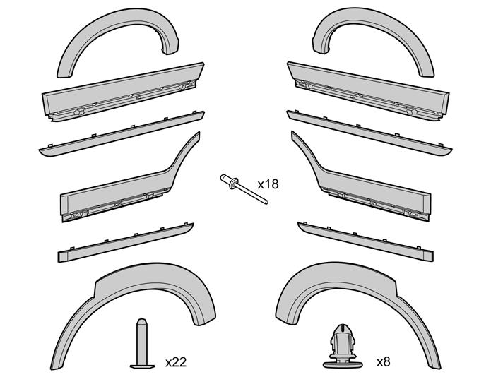
2 Equipment A A IMG R A A M IMG Page 2 / 13
3 IMG Page 3 / 13

4 INTRODUCTION Read through all of the instructions before starting installation. Notifications and warning texts are for your safety and to minimise the risk of something breaking during installation. Ensure that all tools stated in the instructions are available before starting installation. Certain steps in the instructions are only presented in the form of images. Explanatory text is also given for more complicated steps. In the event of any problems with the instructions or the accessory, contact your local Volvo dealer. Accessories such as parking assistance, front/rear and tow bars should be installed on the car before the body kit. 1 Wash and degrease the car. It is important that the surfaces on which the side panels will be mounted are completely free of tar and other road dirt. 2A Removing the front wheel arch extensions Illustration A Drill out the five pop rivets (1) holding the front fender widener to the edge of the wheel arch. Use a Ø 6 mm (1/4") diameter drill bit. Remove the rivet swarf and ensure that none remains in the holes. Illustration B Carefully pry off the front lower edge of the wheel arch extension. Use a plastic weatherstrip tool. R Page 4 / 13


5 2B Do not damage the paint work. Fold out the front lower edge of the wheel arch extension to expose the first mounting clip Insert the weatherstrip tool at the side of the clip, between the panel and the wheel arch extension. Twist the weatherstrip tool to pull the clip away from the edge of the wheel arch or so that it breaks. Then continue in the same way until all five clips have released. Remove the wing extension. Place the wing extension to one side. This will not be reused. R Removal of the lower trim strip on the front and rear doors. Use the weatherstrip tool to pry the rear edge of the trim strip until the tape comes away at the bottom and top edges. Do not damage the paint work. Push the trim strip to one side to expose the first clip Remove the clip in the same way as for the clips on the wheel arch extension R Pry the trim strip off working forwards. Remove the last clip in the same way as previously Place the trim strip to one side. This will not be reused. Page 5 / 13


6 4A Removing the rear wheel arch extensions Illustration A Drill out the four pop rivets (1) holding the fender widener to the edge of the wheel arch. Use a Ø 6 mm (1/4") diameter drill bit. Remove the rivet swarf and ensure that none remains in the holes. Illustration B Carefully pry off the front lower edge of the wheel arch extension. Use a plastic weatherstrip tool. 4B R Do not damage the paint work. Fold out the front lower edge of the wheel arch extension to expose the first mounting clip Insert the weatherstrip tool at the side of the clip, between the panel and the wheel arch extension. Twist the weatherstrip tool to pull the clip away from the edge of the wheel arch or so that it breaks. Then continue in the same way until all six clips have released. Pull the two mounting hooks at the rear edge of the wheel arch extension off from their mountings. R Remove the wing extension. Place the wing extension to one side. This will not be reused. 5 Removing stone-chip protection Remove the stone-chip protection at the rear edge of the rear door. R Page 6 / 13

7 6 Cleaning panel surfaces Wash the entire surface of where the new decor panels and fender wideners shall be installed. Use cleaner H part no Wipe dry. R Marking the primer surface on the bodywork Two people must help each other to mark the primer surface on the bodywork. Remove the side panel components from the packaging Check how the mounting tape is positioned on the components. This determines where the primer must be applied and where the markings must be made Clean the protective film with a moist cloth. Use a mixture of 30% windshield washer fluid and 70% water. There must not be any dirt or grease on the protective film on the panel. This could contaminate the bodywork when making markings in the next step. Wipe dry. Page 7 / 13
 8 pcs.")
8 8 Marking the panels' outer contours Check-fit the panels, according to steps 11-15, and mark these outer contours with a Whiteboard pen. Leave the mounting tape's protective film in place and make sure that the panels are aligned horizontally. Install clips on side panel (door) 8 pcs. IMG Applying primer to the bodywork Take the primer part no and cotton buds from the kit. The primer must be applied to the whole car in one operation. Any spillage must be wiped up immediately. Apply primer inside the panels' outer contours. It is important that nothing ends up outside the markings, especially by the panels' top sides where there shall be a gap of approx. 1 mm between the primer and the marking. Allow the primer to harden for 15 minutes. Caution! The side panels shall be installed at the earliest 15 minutes, and at the latest 3 hours, after applying the primer. Page 8 / 13
 between trailing edge fender widener and the front fender's trailing edge is obtained (B).")

9 10 Fastening side panel, front fender Fold up the protective film on the sides of the panel (A). Be careful so that the protective film does not come off on the back of the panel. Make sure that the measurement 2mm (5/64" ) between trailing edge fender widener and the front fender's trailing edge is obtained (B). Press the panel into place against the front fender at every point that there is tape. IMG Apply a pressure of 1-2 kg/cm² (14-28 lbf/in²) around the entire panel so that the tape sticks firmly. 11 Fastening side panel, rear fender Open the back door. Bend in the panel against the rear fender while making sure that the side panel's guide pin fits in the corresponding hole in the edge of the wheel arch (1). Place the raised edge (guide edge) on the fender widener buttto-butt with bumper as shown (2). Place the corner in the door opening (3). IMG Make sure that the panel does not touch the back door. Fold up the protective film on the sides and the lower edge of the panel. Be careful so that the protective film does not come off on the back of the panel. Press the panel into place against the rear fender at every point that there is tape. Apply a pressure of 1-2 kg/cm² (14-28 lbf/in²) around the entire panel so that the tape sticks firmly. Page 9 / 13

10 12 Fastening side panel, back door Fold up the protective film over the edge of the panel. Remove the lower protective film on the side panel. Fold in the panel with the lower edge first and carefully insert the panel's guide pin as well as click in the two clips in the door side's hole without fastening the tape on the panel's corners. Move the panel as close as possible to the door side without the tape in the corners fastening. Make sure that the panel's rear upper corner (1) follows the same line as the rear fender's side panel (there is some clearance between the guide pins and the holes in the door side). IMG Press the panel into place at the upper corners and carefully remove the upper protective film by pulling it off from both ends at the same time. Make sure that the protective film does not come off on the back of the panel. The panel may have contact with the side of the door with some pressure. Press the upper section of the panel into place against the side of the door. Press the panel so that it is firmly secured. Apply a pressure of 1-2 kg/cm² (14-28 lbf/in²) around the entire panel so that the tape sticks firmly. 13 Fastening decor strip, back door Remove the protective film on the strip and move it in to correct position on the side panel. Make sure that the line between the decor strip and panel is obtained by pressing up the upper corners on the strip (1). Apply a pressure of 1-2 kg/cm² (14-28 lbf/in²) around the entire panel so that the tape sticks firmly. Press in the 5 clips in the lower edge on the side panel. IMG Page 10 / 13

11 14 Fastening side panel, front door Fold up the protective film on the panel's upper edge. Loosen the lower protective film on the side panel. Fold in the panel with the lower edge first, carefully insert the panel's guide pin as well as click in the two clips in the door side's hole without fastening the tape on the panel's corners. Make sure that the panel's rear/upper corner follows the same line as the back door's side panel (there is some clearance between the guide pins and the holes in the door side). Press the panel into place at the upper corners and carefully remove the upper protective film by pulling it off from both ends at the same time. IMG Make sure that the protective film does not come off on the back of the panel. The panel may have contact with the side of the door with some pressure. Press the upper part of the panel into place against the side of the door. Press the panel so that it is firmly secured. Apply a pressure of 1-2 kg/cm² (14-28 lbf/in²) around the entire panel so that the tape sticks firmly. 15 Fastening decor strip, front door Remove the protective film on the strip and move it in to correct position on the side panel. Make sure that the line between the decor strip and panel is obtained by pressing up the upper corners on the strip (1). Apply a pressure of 1-2 kg/cm² (14-28 lbf/in²) around the entire panel so that the tape sticks firmly. Press in the 5 clips in the lower edge on the side panel. IMG Page 11 / 13


12 16 Fold in the mounting lugs on the front fender's side panel, so that the holes in these align with the holes in the fender liner. IMG Pop rivet the fender widener's edges to the fender liners along the wheel arches in the front fender. IMG Pop rivet the fender widener's edges to the fender liners along the wheel arches in the rear fender. R Page 12 / 13
13 19 Remove the whiteboard markings with a dry rag. The car must be kept dry and at a temperature of at least 15 C (59 F) for 2 hours Do not wash the car for 72 hours after installing the side panels. Page 13 / 13
Installation instructions, accessories. Body kit
 Installation instructions, accessories Instruction No 31265373 Version 1.1 5 Part. No. Body kit IMG-256263 Volvo Car Corporation Body kit - 31265373 - V1.1 Page 1 / 42 Equipment A0000162 A0000163 IMG-239664
Installation instructions, accessories. Parking assistance, rear
 Installation instructions, accessories Instruction No 31330676 Version 1.4 Part. No. 30758088, 9487266, 30786087, 31359215 Parking assistance, rear Volvo Car Corporation Parking assistance, rear- 31330676
Installation instructions, accessories. Satellite radio, Sirius
 Installation instructions, accessories Instruction No 31201184 Version 1.3 5 Part. No. 31296261, 31359449 Satellite radio, Sirius IMG-246543 Volvo Car Corporation Satellite radio, Sirius- 31201184 - V1.3
Installation instructions, accessories. Electric engine block heater, 230V, 5 cyl diesel
 Installation instructions, accessories Instruction No 30795311 Version 1.2 Part. No. 31373138 Electric engine block heater, 230V, 5 cyl diesel IMG-256423 Volvo Car Corporation Electric engine block heater,
Installation instructions, accessories. Electric engine block heater, connector outlet, 4-cyl
 Installation instructions, accessories Instruction No 31359444 Version 1.2 5 Part. No. 31359438 Electric engine block heater, connector outlet, 4-cyl IMG-247665 Volvo Car Corporation Electric engine block
Installation instructions, accessories. Parking assistance, camera, front (Plug-in Hybrid)
") Installation instructions, accessories Instruction No 31428779 Version 1.0 5 Part. No. 9487189 Parking assistance, camera, front (Plug-in Hybrid) IMG-374543 Volvo Car Corporation Parking assistance, camera,
Installation instructions, accessories Instruction No 31428779 Version 1.0 5 Part. No. 9487189 Parking assistance, camera, front (Plug-in Hybrid) IMG-374543 Volvo Car Corporation Parking assistance, camera,
Expedition Front Bumper Instructions
 Expedition Front Bumper Instructions QTY 3D PN. FCS PART NUMBER DESCRIPTION 1 691256 A 8 E X D - 1 7 B 635-AAPLN FRONT BUMPER REPLACEMENT HARDWARE SUPPLIED 10 SELF TAPING SCREWS -10 for Front Bumper PLASTIC
Installation instructions, accessories - Fuel driven heater 912-D
 XC90 Section Group Weight(Kg/Pounds) Year Month 8 87 2002 10 XC90 2003 D5244T, XC90 2004 D5244T, XC90 2005 D5244T AW50/51 AWD, XC90 2006 D5244T, XC90 2006 D5244T AW50/51 AWD D5244T R8703687 Page 1 of 20
USB and ipod Music interface
 Installation instructions, accessories Instruction No 30775542 Version 1.2 Part. No. USB and ipod Music interface Volvo Car Corporation USB and ipod Music interface- 30775542 - V1.2 Page 1 / 16 Equipment
Installation instructions, accessories. Multimedia monitor with DVD, Dual screen. Multimedia monitor with DVD, Dual screen V1.
 Installation instructions, accessories Instruction No 30756560 Version 1.2 5 Part. No. 30756177 Multimedia monitor with DVD, Dual screen Volvo Car Corporation Multimedia monitor with DVD, Dual screen-
Sensus Connected Touch
 Installation instructions, accessories Instruction No 31350401 Version 1.2 Part. No. 31399164, 31399165, 31399166 Sensus Connected Touch IMG-378798 Volvo Car Corporation Sensus Connected Touch- 31350401
Installation instructions, accessories. Handsfree, Bluetooth
 Installation instructions, accessories Instruction No 31310097 Version 1.3 5 Part. No. 31285547 Handsfree, Bluetooth Volvo Car Corporation Handsfree, Bluetooth- 31310097 - V1.3 Page 1 / 28 Equipment A0000162
Installation instructions, accessories - Alarm, basic kit S60 / S80 / V70 / V70 XC / XC /
 S60 / S80 / V70 / V70 XC / XC70 Section Group Weight(Kg/Pounds) Year Month 3 36 0.67/1.47 2005 05 S60 2001, S60 2002, S60 2003, S60 2004, S60 2005, S60 2006, S60 2007, S60 2008, S60 2009, S80 (-06) 1999,
Installation instructions, accessories RTI S80
 Installation instructions, accessories Instruction No 8685714 Version 1.0 5 Part. No. RTI S80 Volvo Car Corporation RTI S80-8685714 - V1.0 Page 1 / 25 Equipment A0000161 A0000162 A0801178 D8802049 Page
Installation instructions, accessories. Polestar Performance Intake and Exhaust kit
 Installation instructions, accessories Instruction No 31664128 Version 1.0 Part. No. 31664126, 31664125, 31664522, 31664523 Polestar Performance Intake and Exhaust kit Volvo Car Corporation Polestar Performance
Installation instructions, accessories. Towbar, detachable (Plug-in Hybrid)
") Installation instructions, accessories Instruction No 31373200 Version 1.2 5 Part. No. 31359557, 30791002 Towbar, detachable (Plug-in Hybrid) IMG-371662 Volvo Car Corporation Towbar, detachable (Plug-in
Installation instructions, accessories Instruction No 31373200 Version 1.2 5 Part. No. 31359557, 30791002 Towbar, detachable (Plug-in Hybrid) IMG-371662 Volvo Car Corporation Towbar, detachable (Plug-in
REV READ BEFORE INSTALLATION OF KIT:
 REV. 05-08 QTY 3D PN. FCS PART NUMBER DESCRIPTION 1 691509 A7EDG-7820049-AAPLN EDGE BODY KIT- V6 B PCS & EXH TIPS 1 691256 A 7 E D G - 7 8 20049-BAPLN EDGE BODY KIT- V6 8PCS & EXH TIPS W/HITCH 1 691501
QTY 3D PART NO. FORD SERVICE PN DESCRIPTION VAA6Z A FIESTA 5 DOOR (4) PC. KIT
 PC. KIT") Rev. 08-4 - 2010 QTY 3D PART NO. FORD SERVICE PN DESCRIPTION 1 691620 VAA6Z-5820049-A 2011- FIESTA 5 DOOR (4) PC. KIT HARDWARE SUPPLIED 12 #8 X ¾ SELF DRILLING SCREWS 220 / 18.5 3M VHB DOUBLE FACE TAPE
Rev. 08-4 - 2010 QTY 3D PART NO. FORD SERVICE PN DESCRIPTION 1 691620 VAA6Z-5820049-A 2011- FIESTA 5 DOOR (4) PC. KIT HARDWARE SUPPLIED 12 #8 X ¾ SELF DRILLING SCREWS 220 / 18.5 3M VHB DOUBLE FACE TAPE
394: Handsfree, Bluetooth Handsfree, Bluetooth
 394: Handsfree, Bluetooth S80 (07-), 2008, B8444S, TF-80SC AWD, L.H.D, YV1AH852881073834, 073834 4/1/2013 PRINT 394: Handsfree, Bluetooth Handsfree, Bluetooth Installation instruction: 31310098 INTRODUCTION
Fig A ADDICTIVE DESERT DESIGNS. Preparation: Removal: Release these clips
 Preparation: Disconnect the negative battery terminal. Park the vehicle on level ground and set the emergency brake. We recommend reading through the installation instructions in whole before performing
Installation of Barricade Flat Style Fender Flare Kit (97-06 Wrangler TJ)
") Installation of Barricade Flat Style Fender Flare Kit (97-06 Wrangler TJ) Installation Time: 3-4 Hours Tools Required: 8mm wrench 8mm socket drive #1 Phillips screw driver Pliers Pry bar Electric drill
Installation of Barricade Flat Style Fender Flare Kit (97-06 Wrangler TJ) Installation Time: 3-4 Hours Tools Required: 8mm wrench 8mm socket drive #1 Phillips screw driver Pliers Pry bar Electric drill
Bolt-On/Rugged Fender Flares Nissan Titan (04-15) Please read instructions entirely before installing this product.
 Please read instructions entirely before installing this product.") Please read instructions entirely before installing this product. Hardware Included QTY FUEL DOOR CLIP 1 Bolt Kit Included QTY ALCOHOL TOWELETTE 4 M4 SCREW 1 ALLEN KEY BOLT 42 CLIP.9MM 2 ABRASIVE RESISTANT
Please read instructions entirely before installing this product. Hardware Included QTY FUEL DOOR CLIP 1 Bolt Kit Included QTY ALCOHOL TOWELETTE 4 M4 SCREW 1 ALLEN KEY BOLT 42 CLIP.9MM 2 ABRASIVE RESISTANT
RTS518 - Rhino Heavy Duty 2 & 3 Crossbar System Hyundai iload, imax, i800, H-1.
 RTS518 - Rhino Heavy Duty 2 & 3 Crossbar System Hyundai iload, imax, i800, H-1. NOTE: Please read these instructions carefully prior to installation. Check the contents of kit before commencing fi tment
Installation instructions, accessories. Subwoofer
 Installation instructions, accessories Instruction No 9162298 Version 1.0 5 Part. No. Subwoofer Volvo Car Corporation Subwoofer - 9162298 - V1.0 Page 1 / 24 Equipment A0000162 A0801178 A0000161 R8802817
Installation instruction do88 performance Intercooler for Volvo S60/V60 T6 MY10-
 Installation instruction do88 performance Intercooler for Volvo S60/V60 T6 MY10-1. This instruction shows how to replace the OEM intercoolers with do88 performance intercoolers. At this type of installation
75 5 ENGINE HOOD/DOOR
 OVERHAUL Installation is in the reverse order of the removal. But the installation is indicated only when it has a point. In the RH side, work in the same procedure as in the LH side. 755 750DN01 1. REMOVE
Original BMW Accessories. Installation Instructions.
 Original BMW Accessories. Installation Instructions. Installing the M Performance rear diffuser and Carbon front splitter BMW 5 Series Saloon (F0) BMW 5 Series Touring (F ) Retrofit kit number single-sided
Installation instructions, accessories TV NTSC/PAL
 Instruction No Version Part. No. 8637033 1.0 5 TV NTSC/PAL Page 1 / 17 Page 2 / 17 INTRODUCTION Read through all of the instructions before starting installation. Notifications and warning texts are for
Bolt-On/Rugged Fender Flares Dodge Ram 1500/2500/3500 (09-12) Please read instructions entirely before installing this product.
 Please read instructions entirely before installing this product.") Please read instructions entirely before installing this product. Hardware Included QTY Hardware Included QTY Bolt Kit Included QTY EXTRUSION 29.0ft ALCOHOL TOWELETTE 4 ALLEN KEY BOLT 42 NUT 42 Ensure
Please read instructions entirely before installing this product. Hardware Included QTY Hardware Included QTY Bolt Kit Included QTY EXTRUSION 29.0ft ALCOHOL TOWELETTE 4 ALLEN KEY BOLT 42 NUT 42 Ensure
 INSTALLATION INSTRUCTIONS Accessory Application Publications No. AII 33173 UNDER 2007 ODYSSEY Issue Date JULY 2006 PART LIST Front under spoiler 5 Stepped bolts TOOLS AND SUPPLIES REQUIRED Phillips screwdriver
GENUINE ILLUMINATED SCUFF PLATE
 GENUINE ILLUMINATED SCUFF PLATE INSTALLATION AND USER S INSTRUCTIONS Thank you for purchasing a Genuine Mazda Accessory. Before removal and installation, please thoroughly read these instructions. For
QTY 3D PART NO. DESCRIPTION
 QTY 3D PART NO. DESCRIPTION 1 691032 V6 FRONT AIR DAM 1 691023 SIDE SKIRT RIGHT 1 691024 SIDE SKIRT LEFT 1 691566 V6 DUAL EXHAUST REAR LOWER SKIRT- 8 3M 94 3M ADHESION PROMOTER 24 #8 X ¾ SELF DRILLING
Preparation Part Number: PT Kit Contents Item # Quantity Reqd. Description 1 1 Rear Spoiler 2 1 Hardware Kit. Hardware Bag Contents
 Preparation Part Number: PT478-11170-09 Kit Contents 1 1 Rear Spoiler 2 1 Hardware Kit Hardware Bag Contents 1 4 M5 Nut 2 4 Clip 3 4 Hole Plug Additional Items Required For Installation 1 1 Outer Drill
Included in Hardware Kit. Rear Corners 2-Door. Jeep JK Trail Armor. Set Part #14009 Rev STEP 1 - PRIOR TO INSTALLATION
 Jeep JK Trail Armor Set Part #14009 Rev-2 02-23-11 A) B) C) STEP 1 - PRIOR TO INSTALLATION Bushwacker only approves installing the trail armor according to these written instructions with the hardware
Rev TOOLS & MATERIALS REQUIRED QTY 3D PART NO. DESCRIPTION
 Rev. 04-10 QTY 3D PART NO. DESCRIPTION 1 691609 FRONT BUMPER REPLACEMENT 1 691610 RIGHT SIDE SKIRT 1 691611 LEFT SIDE SKIRT 1 691612 REAR LOWER SKIRT 4 3M 94 3M ADHESION PROMOTER 16 #8 X ¾ SELF DRILLING
Original BMW Accessories. Installation Instructions.
 Original BMW Accessories. Installation Instructions. M Performance Aerodynamics Package Retrofit Kit. BMW 4 Series Coupé (F32) BMW 4 Series Convertible (F33) BMW 4 Series Gran Coupé (F36) Retrofit kit
IMPORTANT: PLEASE RETAIN THIS INSTRUCTION MANUAL FOR FUTURE REFERENCE
 IMPORTANT: PLEASE RETAIN THIS INSTRUCTION MANUAL FOR FUTURE REFERENCE 2009 Toyota RAV-4 Stainless Steel Mesh Grilles L 30 G8P Fine Mesh Part #30-002-09 Quantity Description Part No. Upper Mesh Grille (includes):
Installation instructions, accessories - Electric engine block heater
 S60 / V70 (00-08) / S80 (-06) / V70 XC (01-) / XC70 (-07) / XC90 Section Group Weight Year Month (Kg/Pounds) 8 876 2/4.4 2006 09 S60 2001 D5244T, S60 2002 D5244T, S60 2002 D5244T2, S60 2003 D5244T, S60
GENUINE PARTS INSTALLATION INSTRUCTIONS
 GENUINE PARTS INSTALLATION INSTRUCTIONS 1. 2. 3. 4. DESCRIPTION: Front Protector Kit APPLICATION: G Sedan Sports PART NUMBER: K6010-1NH** (XX Designates color) KIT CONTENTS: Item Qty. Description Part
INSTALLATION INSTRUCTIONS
 INSTALLATION INSTRUCTIONS Accessory Application Publications No. UNDER 2007 CIVIC SI All 33529 Issue Date AUG 2006 PARTS LIST Rear under spoiler Clip Rubber washer 6 Flange bolts 6 Flange nuts TOOLS REQUIRED
SAFETY THIS PRODUCT IS FOR OFFROAD USE ONLY. ALL LIABILITY FOR INSTALLATION AND USE RESTS WITH THE OWNER.
 SAFETY Your safety and the safety of others is very important. In order to help you make informed decisions about safety, we have provided installation instructions and other information. These instructions
5 Mechanisms and accessories
 5 Mechanisms and accessories 51A SIDE OPENING ELEMENT MECHANISMS 52A NON-SIDE OPENING ELEMENT MECHANISMS 54A WINDOWS 55A EXTERIOR PROTECTION 56A EXTERIOR EQUIPMENT 57A INTERIOR EQUIPMENT 59A SAFETY ACCESSORIES
Front Door Lower Trim Removal and Installation. 1. Front Door Lower Trim - Remove. 1. Remove the cap (A), then remove the screw.
, then remove the screw.") Front Door Lower Trim Removal and Installation 1100 Page 1 of 4 http://tor.in.honda.com/rjanisis/pubs/sm/1/2/contents/enu/61tlad/rin/sct/sc/sys/r001100_... Front Door Lower Trim Removal and Installation
Front Door Lower Trim Removal and Installation 1100 Page 1 of 4 http://tor.in.honda.com/rjanisis/pubs/sm/1/2/contents/enu/61tlad/rin/sct/sc/sys/r001100_... Front Door Lower Trim Removal and Installation
GENUINE PARTS INSTALLATION INSTRUCTIONS
 GENUINE PARTS INSTALLATION INSTRUCTIONS DESCRIPTION: APPLICATION: PART NUMBER: KIT-CARBON FIBER REAR SPOILER INFINITI Q50 T99J1 J5000 KIT CONTENTS: Item A B C D Qty. 1 4 1 1 Part Description Spoiler Assembly
RTS536 Toyota Prado 150 Track Mount
 Important: Please read these instructions carefully prior to installation. Please refer to your fi tting instruction to ensure that the track mount system is installed in the correct location. Check the
TONNEAU COVER INSTALLATION INSTRUCTION. Toyota Hilux 407L
 TONNEAU COVER INSTALLATION INSTRUCTION Toyota Hilux 407L Piece Tonneau Cover Place these instructions in vehicle s glove box after installation is complete Care Instructions: Clean Tonneau Cover with a
WARNING! 2 x Crossbars = 5kg. ? kg
 WARNING!! ü! ü! km/h X 2 x Crossbars = 5kg? kg WARNING! Important Load Carrying Instructions With utility vehicles, the cabin and the canopy move independently. Roofracks and vehicle can be damaged if
Original BMW Accessories. Installation Instructions
 Original BMW Accessories. Installation Instructions Mud flaps retrofit BMW X5/ X5M (E70) Retrofit kit no.: 82 16 0414 673 82 16 0 41 6 162 82 1 6 0 41 6 1 61 82 16 0 428 284 82 16 0 41 4 67 4 82 16 0 420
INSTALLATION INSTRUCTIONS
 INSTALLATION INSTRUCTIONS Accessory Application Publications No. SPOILER (LOW) 2011 CIVIC 4-DOOR All 44416 Issue Date AUG 2010 PARTS LIST Trunk spoiler Right trunk spring (marked red) Left trunk spring
393: Multimedia system for the rear seat Multimedia system for the rear seat
 393: Multimedia system for the rear seat S80 (07-), 2008, B8444S, TF-80SC AWD, L.H.D, YV1AH852881073834, 073834 4/1/2013 PRINT 393: Multimedia system for the rear seat Multimedia system for the rear seat
900 Installation instructions. SCdefault
 SCdefault 900 Installation instructions SITdefault Parking assistance (SPA) MONTERINGSANVISNING INSTALLATION INSTRUCTIONS MONTAGEANLEITUNG INSTRUCTIONS DE MONTAGE Accessories Part No. Group Date Instruction
Rear Door: Service and Repair REAR DOOR
 2007 Toyota Matrix L4-1.8L (1ZZ-FE) Copyright 2013, ALLDATA 10.52 Page 1 Rear Door: Service and Repair REAR DOOR Rear Door 2007 Toyota Matrix L4-1.8L (1ZZ-FE) Copyright 2013, ALLDATA 10.52 Page 2 ISASSEMBLY
Parts and Accessories. Installation instructions.
 Parts and Accessories. Installation instructions. Retrofit - Front/rear splash guard BMW 7 Series (E 65 / E 66) Facelift 3/25 Retrofit kit no.: 82 6 43 529, 82 6 397 77. Installation time The installation
Original BMW Accessories. Installation Instructions.
 Original BMW Accessories. Installation Instructions. M Performance Aerodynamics Package Retrofit Kit. BMW 3 Series Saloon (F30) BMW 3 Series Saloon Long Version China (F35) BMW 3 Series Touring (F31) BMW
INSTALLATION INSTRUCTIONS
 INSTALLATION INSTRUCTIONS Accessory Application Publications No. SPOILER (LOW) CIVIC 4-DOOR All 30833 Issue Date SEP 2005 PARTS LIST Trunk spoiler Right trunk spring (marked red) Left trunk spring (marked
Installation Manual Volvo C30 T5 Front Mount Intercooler System
 Installation Manual Volvo C30 T5 Front Mount System Volvo C30 T5 System / Installation Manual i C Contents Important Information i Parts List i Required Tools and Materials 1 1.0 - Vehicle Preparation
 INSTALLATION INSTRUCTIONS Accessory Application Publications No. 2009 CIVIC HYBRID All 40191 Issue Date AUG 2008 PARTS LIST Rear under spoiler 2 Step bolts 4 Self-tapping screws TOOLS REQUIRED Phillips
1 of 21 9/30/2011 3:16 PM
 Engine Block Heater, Service and Repair, Removal and Replacement: Ele... 1 of 21 9/30/2011 3:16 PM 2005 Volvo S60 L5-2.5L Turbo VIN 59 B5254T2 Engine Block Heater Service and Repair, Removal and Replacement:
Installation instruction do88 Intercooler for SAAB 9-3SS/SC 4-cyl Turbo
 Installation instruction do88 Intercooler for SAAB 9-3SS/SC 4-cyl Turbo This instruction shows how to replace the OEM intercooler with this performance intercooler. 1. 4. 5. At this type of installation
Installation instruction do88 Intercooler for SAAB 9-3 1,9 TTiD
 Installation instruction do88 Intercooler for SAAB 9-3 1,9 TTiD This instruction shows how to replace the OEM intercooler with this performance intercooler. At this type of installation we always recommend
Toyota Hilux Track Mount (RTS543)
") Important: Please read these instructions carefully prior to installation. Check the contents of this kit before commencing fi tment and report any discrepancies. Place these instructions in the vehicle
Important: Please read these instructions carefully prior to installation. Check the contents of this kit before commencing fi tment and report any discrepancies. Place these instructions in the vehicle
SS1066HF Jeep JK Wrangler Left Hand Drive CRDI4 2.8Litre-I4 Diesel Engine and EGHV6 3.8Litre V6 Gasoline Engine
 SS1066HF Jeep JK Wrangler Left Hand Drive CRDI4 2.8Litre-I4 Diesel Engine and EGHV6 3.8Litre V6 Gasoline Engine Installation Guide Safari SS1066HF Page - 1 of 12 6/10/2009 ITEM PART NO DESCRIPTION QTY
FRONT FENDERS WITH FACTORY INNER FENDERS JEEP WRANGLER TJ/LJ/YJ/CJ7 INSTALLATION INSTRUCTIONS
 FRONT FENDERS WITH FACTORY INNER FENDERS JEEP WRANGLER TJ/LJ/YJ/CJ7 INSTALLATION INSTRUCTIONS TOOLS NEEDED 13mm socket 5/32 Allen head 5/16 wrench or socket 7/16 wrench or socket 7/32 Allen head 5/8 wrench
SAFETY. Read and understand all safety precautions and instructions before installing this product.
 SAFETY Your safety and the safety of others is very important. In order to help you make informed decisions about safety, we have provided installation instructions and other information. These instructions
P Original Series Cargo Van Lift Mounting Instructions Fullsize Ford Van present. Preparing the Gate
 Fullsize Ford Van- 1992-present Preparing the Gate 1. Remove the mounting hardware which is banded to the liftgate. 2. Verify mounting kit (Figure 1 and Table 1). S-400-40 STRAP VAN MOUNTING EAR BENT BRACKET
Installation instructions, accessories - Bluetooth XC / Volvo Car Corporation Göteborg, Sweden
 XC90 Section Group Weight(Kg/Pounds) Year Month 3 393 1/2.2 2008 03 XC90 2003, XC90 2003, XC90 2004, XC90 2004, XC90 2005, XC90 2005, XC90 2006, XC90 2006, XC90 2007, XC90 2007, XC90 2008, XC90 2008, XC90
GENUINE MUD FLAP (FRONT)
") GENUINE MUD FLAP (FRONT) INSTALLATION AND USER S INSTRUCTIONS Thank you for purchasing a genuine Mazda accessory. Before removal and installation, be sure to thoroughly read these instructions. Please
GENUINE MUD FLAP (FRONT) INSTALLATION AND USER S INSTRUCTIONS Thank you for purchasing a genuine Mazda accessory. Before removal and installation, be sure to thoroughly read these instructions. Please
RTS532 ISUZU MU-X LS-U & LS-M Trackmount
 RTS532 ISUZU MU-X LS-U & LS-M Trackmount Assistance from a second person is recommended for the Track install. Please read these instructions carefully prior to installation. Check the contents of kit
Current Range Rover Sport STRUT Collection Installation Manual
 2014 - Current Range Rover Sport STRUT Collection Installation Manual 1 1. Removing Main Grille and Lower Fascia 1.1 Run a line of low tack masking tape across the front of the bumper below the grille
GENUINE MUD FLAP (FRONT)
") GENUINE MUD FLAP (FRONT) INSTALLATION AND USER S INSTRUCTIONS Thank you for purchasing a Genuine Mazda Accessory. Before removal and installation, be sure to thoroughly read these instructions. Please
GENUINE MUD FLAP (FRONT) INSTALLATION AND USER S INSTRUCTIONS Thank you for purchasing a Genuine Mazda Accessory. Before removal and installation, be sure to thoroughly read these instructions. Please
Installation instruction do88 Intercooler for SAAB 9-3SS/SC 2,8 V6 Turbo
 Installation instruction do88 Intercooler for SAAB 9-3SS/SC 2,8 V6 Turbo This instruction shows how to replace the OEM intercooler with this performance intercooler. At this type of installation we always
SAFETY. Injury hazard
 SAFETY Your safety and the safety of others is very important. In order to help you make informed decisions about safety, we have provided installation instructions and other information. These instructions
VOLKSWAGEN AMAROK 3 PIECE HARD TONNEAU COVER INSTALLATION INSTRUCTIONS
 VOLKSWAGEN AMAROK 3 PIECE HARD TONNEAU COVER INSTALLATION INSTRUCTIONS Care Instructions: Clean Tonneau Cover with a mild detergent and water solution. Do not use abrasive cleaners or solvents. Place these
D40C HINGE # x Support Plate x M8 Bolt 8 x M8 Washer 6 x M6 20mm Bolts 6 x M6 Washers 19 x Screws
 HINGE # 1017 2 x Support Plate 1018 8 x M8 Bolt 8 x M8 Washer 6 x M6 20mm Bolts 6 x M6 Washers 19 x Screws 2 x Lid mount gas strut bracket 1041 2 x Self tap strut mount 1040 1 x Central Lock bracket 1510
JEEP JK WRANGLER UNLIMITED 4-DOOR Pro-Series Front Replacement Fenders
 PSFF001 2007-2016 JEEP JK WRANGLER UNLIMITED 4-DOOR Pro-Series Front Replacement Fenders HARDWARE INCLUDED 4 6mm x 25mm Hex Bolts 16 10mm x 20mm Button Head Bolts 8 6mm x 12mm x 1.6mm Flat Washers 16 10mm
INSTALLATION INSTRUCTIONS Toyota FJ Cruiser DEMELLO-OFFROAD.
 INSTALLATION INSTRUCTIONS Item Description Vehicle 3 piece Rear Bumper 2007-2014 Toyota FJ Cruiser DEMELLO-OFFROAD www.demello-offroad.com 12785 magnolia ave Riverside ca 92503 Suite 1 phone: 1-951-735-4417
CIRRUS AIRPLANE MAINTENANCE MANUAL
 MODEL SR PASSENGER AND CREW DOORS. DESCRIPTION AND OPERATION Serials 000 thru 00: The two crew/passenger doors incorporate a flush-mount outside door handle, key-operated door lock, and a conventional
SAFETY THIS PRODUCT IS FOR OFFROAD USE ONLY. ALL LIABILITY FOR INSTALLATION AND USE RESTS WITH THE OWNER.
 SAFETY Your safety and the safety of others is very important. In order to help you make informed decisions about safety, we have provided installation instructions and other information. These instructions
INSTALLATION INSTRUCTIONS
 INSTALLATION INSTRUCTIONS Accessory Application Publications No. Bll 30250 UNDER SPOILER 2006 RSX Issue Date JULY 2005 PARTS LIST Rear under spoiler 5 Stepped bolts 2 Bolts 7 Flange nuts, 6 mm 3 Square
INSTALLATION INSTRUCTIONS
 INSTALLATION INSTRUCTIONS Accessory Application Publications No. AII 24642 BODY SIDE CLADDING 2003 CR-V P/N 08P21-S9A-100 Issue Date OCT 2002 PARTS LIST Right rear bumper piece Right front fender piece
Wheel Arch Trim Set. Installation Manual. This section covers installation of the wheel arch trim set.
 Wheel Arch Trim Set FORESTER Wheel Arch Trim Set EN PART # E20SSG000 This section covers installation of the wheel arch trim set. Installation Manual Note: Before performing installation, be sure to read
LANCER EVOLUTION (2008 ) MUD FLAP MZ531356EX (Black with aluminum plate) MZ531357EX (Black standard) INSTALLATION AND HANDLING INSTRUCTIONS
 MUD FLAP MZ531356EX (Black with aluminum plate) MZ531357EX (Black standard) INSTALLATION AND HANDLING INSTRUCTIONS") LANCER EVOLUTION (2008 ) MUD FLAP MZ531356EX (Black with aluminum plate) MZ531357EX (Black standard) INSTALLATION AND HANDLING INSTRUCTIONS Black with aluminum plate -MZ531356EX Black standard -MZ531357EX
LANCER EVOLUTION (2008 ) MUD FLAP MZ531356EX (Black with aluminum plate) MZ531357EX (Black standard) INSTALLATION AND HANDLING INSTRUCTIONS Black with aluminum plate -MZ531356EX Black standard -MZ531357EX
Installation Instructions Bolt-On Fender Flares Ford F150 (09-12) Part #17394
 Part #17394") Please read instructions entirely before installing this product. Hardware Included QTY Hardware Included QTY Bolt Kit Included QTY EXTRUSION 29.5ft ALCOHOL TOWELETTE 4 BLACK HEX BOLT 42 RETAINING CLIP.9mm
Please read instructions entirely before installing this product. Hardware Included QTY Hardware Included QTY Bolt Kit Included QTY EXTRUSION 29.5ft ALCOHOL TOWELETTE 4 BLACK HEX BOLT 42 RETAINING CLIP.9mm
Front Grille Replacement
 Document ID: 4298678 Page 1 of 1 2017 Cadillac XT5 XT5 Service Manual Europe, Korea, N America, Other IO 9325297 Document ID: 4298678 Front Grille Replacement Front Grille Replacement Preliminary Front
A. Preparing the charge harness. Start by removing the plastic covers by the battery terminal.
 twist battery relocate kit and harness. Step 1 A. Remove battery. Start by removing the negative battery cable and then the positive. After removing the battery cables remove the battery hold down bracket.
ARMOR UP FOR YOUR NEXT ADVENTURE! 6530 Federal Blvd. Lemon Grove, CA (844) , ext
 , ext") ARMOR UP FOR YOUR NEXT ADVENTURE! 6530 Federal Blvd. Lemon Grove, CA 91945 1(844)726-3373, ext. 102 info@pelfreybilt.com www.pelfreybilt.com 2016+ Toyota Tacoma Front Plate Bumper Start by removing the
ARMOR UP FOR YOUR NEXT ADVENTURE! 6530 Federal Blvd. Lemon Grove, CA 91945 1(844)726-3373, ext. 102 info@pelfreybilt.com www.pelfreybilt.com 2016+ Toyota Tacoma Front Plate Bumper Start by removing the
WARNING. When installed in accordance with these instructions, the front protection bar does not affect operation of the SRS airbag.
 Part Number: 343870 F/Kit 17557 Product Deluxe Combination Winch and Non Winch Bull Bar Description: Suited to Nissan XTERRA 05ON USA Only vehicle/s: WARNING REGARDING VEHICLES EQUIPPED WITH SRS AIRBAG;
DODGE RAM WITHOUT FENDER FLARES FRONT MUD GUARD INSTALLATION INSTRUCTIONS
 DODGE RAM WITHOUT FENDER FLARES FRONT MUD GUARD INSTALLATION INSTRUCTIONS PART NO: 5817 Please read instructions thoroughly before installation. Tools Required Short Phillips screwdriver Center punch Drill
SAFETY SENSORS FIELD OF VIEW WILL BE ALTERED WITH USE OF THE REPLACEMENT BUMPER. Injury hazard
 SAFETY Your safety and the safety of others is very important. In order to help you make informed decisions about safety, we have provided installation instructions and other information. These instructions
GROSS LOAD CAPACITY WHEN USED AS A WEIGHT CARRYING HITCH: 2,000 LBS. TRAILER WEIGHT & 200 LBS. TONGUE WEIGHT.
 PAGE 1 0F 6 GROSS LOAD CAPACITY WHEN USED AS A WEIGHT CARRYING HITCH: 2,000 LBS. TRAILER WEIGHT & 200 LBS. TONGUE WEIGHT. WARNING: ALL NON-TRAILER LOADS APPLIED TO THIS PRODUCT MUST BE SUPPORTED BY 18050
Original BMW Accessories. Installation Instructions.
 Original BMW Accessories. Installation Instructions. Performance Aerodynamics Package Retrofit Kit. BMW X6 (E 7, E72) Retrofit kit No.: Number Component designation Type Installation time (h) 5 9 2 62
SUBARU FORESTER - SIDE STEP DIESEL VERSION INSTALLATION INSTRUCTIONS
 SUU FORESTER - SIDE STEP DIESEL VERSION INSTALLATION INSTRUCTIONS SS00 VEHICLE DESCRIPTION: PART NUMBER: SUU FORESTER SACC00 R 9 L 0 Care Instructions: Clean Side Steps with a mild detergent and water
QTY 3D PN. FCS PART NUMBER DESCRIPTION
 Rev.05-08 QTY 3D PN. FCS PART NUMBER DESCRIPTION 1 691224 A6ZEP-17B635-AAPLN MKZ FRONT AIR DAM 1 691202 A6ZEP-5410154-AAPLN MKZ SIDE SKIRT RH 1 691203 A6ZEP-5410155-AAPLN MKZ SIDE SKIRT LH 1 691225 A6ZEP-17E957-AAPLN
QTY 3D PN. FCS PART NUMBER DESCRIPTION
 QTY 3D PN. FCS PART NUMBER DESCRIPTION 1 691544 A8FOC-17B635-APL FOCUS FRONT AIR DAM 1 691549 A8FOC-17E957-APL FOCUS REAR LOWER 1 691548 A8FOC-10154-APL FOCUS RIGHT SIDE SKIRT 1 691547 A8FOC-10155-APL
GENUINE PARTS INSTALLATION INSTRUCTIONS
 GENUINE PARTS INSTALLATION INSTRUCTIONS DESCRIPTION: APPLICATION: PART NUMBER: Hood Bug Deflector Pathfinder T99D5 9PJ0A KIT CONTENTS: Item Qty. A 2 Inner Clip A B 2 Outer Clip B C 2 Wing Clip C D 1 Hood
WARNING! 2 x Crossbars = 5kg
 WARNING!! ü!! km/h 2 x Crossbars = 5kg? kg - Please refer to your vehicle manufacturers handbook for maximum roof load capacity. - Any load transported on Roof Racks must be evenly distributed. - Instructions
1. Front Fascia Removal 1.1 Remove the 6 plastic clips that secure the upper valance, then remove. 1.2 Remove 6 upper bolts that hold the grille and f
 STRUT 2015 GMC Denali Collection Installation Manual " 1. Front Fascia Removal 1.1 Remove the 6 plastic clips that secure the upper valance, then remove. 1.2 Remove 6 upper bolts that hold the grille and
POLY TIP-DOWN WINDSHIELD KIT
 POLY TIP-DOWN WINDSHIELD KIT P/N 2883261 APPLICATION Verify accessory fitment at Polaris.com. BEFORE YOU BEGIN Read these instructions and check to be sure all parts and tools are accounted for. Please
CERTAIN 2005 MODEL YEAR FIVE HUNDRED, MONTEGO AND CERTAIN 2005 AND 2006 MODEL YEAR FREESTYLE VEHICLES DOOR LATCH WATER PROTECTION
 CERTAIN 2005 MODEL YEAR FIVE HUNDRED, MONTEGO AND CERTAIN 2005 AND 2006 MODEL YEAR FREESTYLE VEHICLES LATCH WATER PROTECTION ATTACHMENT III PAGE 1 OF 9 OVERVIEW Depending on vehicle and build date, this
Channel Mount Generic Instructions (RDM01).
.") Important: Please read these instructions carefully prior to installation. Please refer to your fi tting instruction to ensure that the Roof Rack System is installed in the correct location. Check the
Important: Please read these instructions carefully prior to installation. Please refer to your fi tting instruction to ensure that the Roof Rack System is installed in the correct location. Check the