WATER COOLED AIR CONDITIONING UNITS MODEL CVWSEK-060 WATER SIDE ECONOMIZER FOR CSV060B VERTICAL R-410A STYLE B R-410A
|
|
|
- Molly Hampton
- 5 years ago
- Views:
Transcription
 MODEL CVWSEK-060 WATER SIDE ECONOMIZER FOR CSV060B VERTICAL R-410A STYLE B R-410A Issue Date: May 30,")
1 WATER COOLED AIR CONDITIONING UNITS INSTALLATION, OPERATION, & MAINTENANCE SUPERSEDES IOM1 (612) Form IOM1 (514) MODEL CVWSEK-060 WATER SIDE ECONOMIZER FOR CSV060B VERTICAL R-410A STYLE B R-410A Issue Date: May 30, 2014


2 IMPORTANT! READ BEFORE PROCEEDING! GENERAL SAFETY GUIDLINES This equipment is a relatively complicated apparatus. During installation, operation, maintenance or service, individuals may be exposed to certain components or conditions including, but not limited to: refrigerants, oils, materials under pressure, rotating components, and both high and low voltage. Each of these items has the potential, if misused or handled improperly, to cause bodily injury or death. It is the obligation and responsibilty of operating/service personnel to identify and recognize these inherent hazards, protect themselves, and proceed safely in completing their tasks. Failure to comply with any of these requirements could result in serious damage to the equipment and the property in which it is situated, as well as sever personal injury or death to themselves and people at the site. This document is intended for use by owner-authorized operating/service personnel. It is expected that this individual possesses independent training that will enable them to perform their assigned tasks properly and safely. It is essential that, prior to performing any task on this equipment, this individual shall have read and understood this document and any referenced materials. This individual shall also be familiar with and comply with all applicable governmental standards and regulations pertaining to the task in question. SAFETY SYMBOLS The following symbols are used in this document to alert the reader to areas of potential hazard. DANGER indicates an imminently hazardous situation which, if not avoided, will result in death or serious injury. CAUTION identifies a hazard which could lead to damage to the machine, damage to other equipment and/or environmental pollution. Usually and instruction will be given, together with a brief explanation. WARNING indicates a potentially hazardous situation which, if not avoided, could result in death or serious injury. NOTE is used to highlight additional information which may be helpful to you. 2
3 All wiring must be in accordance with published specifications and must be performed ONLY by qualified service personnel. Johnson Controls will not be responsible for damages/problems resulting from improper connections to the controls or application of improper control signals. Failure to follow this will void the manufacturers warranty and cause serious damage to property or injury to persons. TABLE OF CONTENTS 4 Economizer Coil Installation 6... Economizer Piping & Valve Installation 12 Temperature Control Panel Installation 14.. Unit Schematic Diagram 14 WSE Harness Connection 14.. Sequence of Operation PRIOR TO INSTALLING OR SERVICING THE UNIT, LOCK ALL ELECTRICAL POWER SUPPLY SWITCHES IN THE OFF POSTION. FAILURE TO DISCONNECT POWER SUPPLY MAY RESULT IN ELECTRICAL SHOCK OR EVEN DEATH. 3
4 GENERAL This kit includes all necessary terminations and hardware, for installing the waterside economizer assembly to the B Generation water-cooled air conditioners. COIL INSTALLATION 1) Position the drain pan using the notched flange of the drain pan according to illustration. Make sure the drain pan is level, do not force it. Push the drain pan firmly against the unit; using self-drilling screws, attach drain pan through the pre-punched holes in the notched flange and support angles. 2) Pilot hole locations for attaching the economizer coil are pre-punched in the vertical corner posts of the unit; three holes on each side of the return air opening. (Note: early model units require field marking of hole locations temporarily place the coil in the drain pan, center the coil over the return air opening, and mark the six fastening hole locations on the vertical coil flanges). Drill out the pilot holes to 3/8 diameter. 3) Carefully lift the WSE coil and place it inside of the drain pan, coil connections facing left side of the unit (see illustration). Push the WSE Coil against the Brackets; align holes on the WSE Coil flange with mating holes on the vertical corner posts. 4) Slide provided bolts through the mounting holes on the corner posts, and the WSE Coil flange. Insert bolts, threaded end first, working from interior face of corner posts (remove evaporator section service panels for access). 5) Tighten the WSE Coil to the unit using provided nuts and lock-washers. 6) Attach unit filter rack to entering air face of waterside economizer coil, using self-drilling screws. Applies ONLY to DELUXE Water Side Economizer Kit 7) After the unit piping has been completed, attach Return Bends Cover and Header Cover using provided selfdrilling screws. Exercise care when working around the sharp metal edges of door panels or flanges. These edges can be sharp, and can cause injury. 4

")
5 Attach Drain Pan with screws at 3 locations along horizontal flange ECONOMIZER COIL DRAIN PAN SUPPORT ANGLE Attach Drain Pan Support Angles to vertical corner posts of unit (3 screws per support bracket) 5
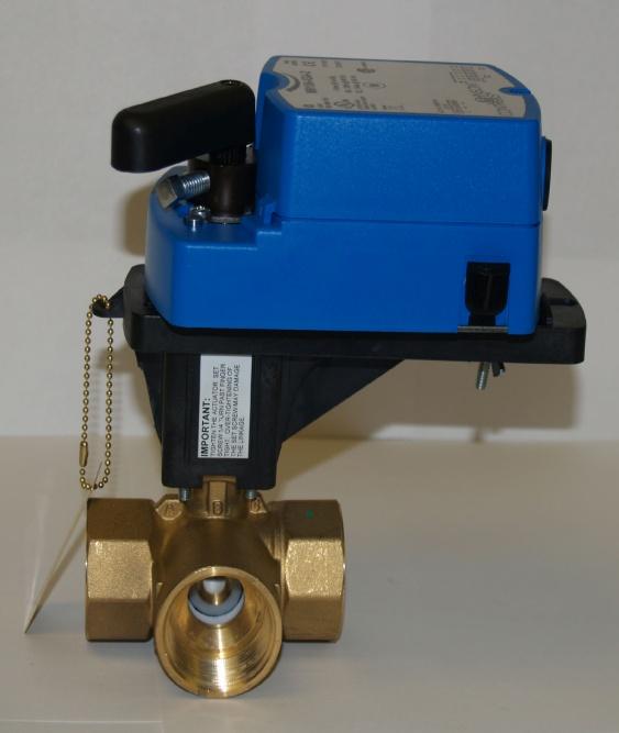
6 WATERSIDE ECONOMIZER PIPING & VALVE INSTALLATION 1) Refer to the accompanying illustrations for recommended piping and valve mounting layout. The piping layout may be varied from that illustrated, to suit on-site conditions or requirements, provided that the correct water flow arrangement is maintained. The 3-way diverting valve ports are marked A, B, and C. Should the common port need to be changed from port C to port A, see supplementary instruction sheet #WSEK-INS-02, packed with the diverting valve. Proper orientation of the valve ports is critical for correct operation of the economizer cycle. If additional clearance between the valve actuator motor and the economizer piping is required to facilitate mounting of the valve with the ports in the correct orientation, the actuator motor mounting plate may be rotated to a different position (see supplementary instruction sheet #WSEK-INS-02). 2) Wrought copper adapters are provided with the kit to adapt the 3 X 1 NPT valve connections. The balance of required fittings, and the straight tube lengths, must be field provided unless DELUXE Kit has been purchased (see piping layout illustrations). 3) The copper adapters for the 3-way valve should be first soldered to the short lengths of tubing (elbows) connecting them to the adjacent fittings, before being threaded into the valve body. DO NOT install the valve actuator until piping assembly is complete. A lowtemperature solder alloy should be used to prevent annealing or out-of round distortion which can occur with high temperature brazing. Use a good quality pipe sealant on the threaded fittings, and fully tighten the adapters into the brass valve body (Torque should not exceed 75 ft-lb). 4) Assemble the tubing and fittings into the correct arrangement as shown. Tack all tubes in place before soldering to ensure proper fit-up. 5) It is recommended that the connection of the economizer coil bypass pipe, to the CSV condenser water inlet, be performed by cutting off the factory installed threaded adapter, and extending the inlet pipe to the outside of the cabinet by use of a straight coupling. If desired, rather then using the factory installed threaded adapter, the condenser water outlet may also be extended to the outside of the cabinet, in the same manner. (See accompanying photo and illustrations) 6) Pressure test the completed piping assembly with nitrogen. Test pressure should at least equal the working water supply pressure to the unit (Maximum pressure rating for the 3-way diverting valve is 580 psig). 7) Locate the remote electronic temperature sensor (it will be attached to the Temperature Control Panel assembly). The sensor must be securely attached to the surface of the incoming water supply line, upstream of the 3-way valve (use wire ties, tape, or gear clamps). The two sensor leads must be connected to the terminal strip on the Temperature Control Panel. A wire routing hole is provided in the condenser corner post of the unit (early model units require field punching use a wire protection bushing). 8) Insulate all exposed water piping to prevent sweating; ensure that the water temperature sensor location is well insulated. Insulation should cover horizontal stub-outs on economizer coil; insulation of the vertical coil headers is not required. 9) Install actuator motor to the 3-way diverting valve. Before tightening the self-centering shaft adapter, manually rotate the diverting valve stem to the fully counter-clockwise position. The actuator motor position should be in the fully counter-clockwise position; if not, depress the black de-clutch button and rotate the shaft adapter assembly to the fully CCW position stop. Slide the anti-rotation bracket forward to engage the clip on the connection end of the actuator motor. Do not seat the anti-rotation bracket at the end of the slot; allow sufficient end-play for the motor to float on the valve platform. 10) Remove the cover from the actuator, and connect three wire leads to the terminal strip. Lead length must be sufficient to reach the terminal strip of the Temperature Control Panel, previously installed in the compressor compartment of the unit. See Panel wiring diagram for proper terminal connections. 6
7 7
8 Piping Parts Supplied in DELUXE KIT Part # Qty Description CLR ELBOW - 1-1/8" LG RADIUS 90DEG CxC CST-9118LR 2 ELBOW -STREET LG RAD. 1-1/8" 90DEG CxF RDC COUPLING - REDUCER 1-1/8"-7/8" CPA-1181M 3 1-1/8 ODS X 1" MPT ADAPTER CPA-1181F 1 1-1/8 ODS X 1" FPT ADAPTER CPT COPPER TEE - 1-1/8" CxCxC RTL /2" PLUMBING TUBING - 1" NOM, TYPE L RTL /2" PLUMBING TUBING - 1" NOM, TYPE L RTL /2" PLUMBING TUBING - 1" NOM, TYPE L RTL /2" PLUMBING TUBING - 1" NOM, TYPE L RTL /4" PLUMBING TUBING - 1" NOM, TYPE L RTL /16" PLUMBING TUBING - 1" NOM, TYPE L RTL /16" PLUMBING TUBING - 1" NOM, TYPE L RTL /8" PLUMBING TUBING - 1" NOM, TYPE L RTL /4" PLUMBING TUBING - 1" NOM, TYPE L RTL /8" PLUMBING TUBING - 1" NOM, TYPE L 8
9 ASSEMBLY A ASSEMBLY B 9
10 ASSEMBLY C ASSEMBLY D 10
11 CONTROL PANEL INSTALLATION - WATERSIDE ECONOMIZER Each Waterside Economizer is shipped with a pre-wired Water Temperature Control / Compressor Staging Panel. The panel is complete with a pre-terminated wiring harness, for connection to the economizer plug on the microprocessor control board of the water-cooled unit. Installing Temperature Control Panel 1) The Temperature Control Panel fixture is intended for mounting on the wide condenser clamp rail, supplied with the economizer kit (see photo below). Fasten the panel feet to the rail, using the provided self-drilling screws. 2) Route the pre-terminated 4-wire harness towards the back of the main electrical panel. The harness wiring should be kept away from hot gas piping, and the top of the compressor shell. Pass the wiring into the low voltage section of the main electrical panel, through the thermostat wire entrance hole (see photo below). 3) On the microprocessor, locate the Economizer pin P4 and unplug the two Yellow/Red jumper wires Y1-OUT and ECON and connect these leads to the corresponding colored Yellow/Red harness wires (see table below). On pin P5, connect the G-OUT wire lead to corresponding colored harness wire Gray/Red. Using the provided ¼ tab adapter, create a dual connection on the C-Common tab on the microprocessor board and connect the White harness wire to this dual connection at C. See table below for connecting the harness wires to the corresponding economizer plug connection leads and Common tab on the Microprocessor Board. See wiring schematic for information on pin P4 and C (Common locations). Single and Dual Compressor Units WSE Control Harness Wire # Color Connection ID WSE Temp/Staging Panel Microprocessor Board 1 Yellow/Red TB3-A1 Y1-OUT (P4) 2 Yellow/Red TB3-A2 ECON (P4) 3 Gray/Red TB3-A3 G-OUT (P4) 4 White TB3-A5 C 4) Connect the spade terminals of the other end of the WSE harness to the correspond terminals on TB3 as indicated in the above table. See wiring schematic for more information. 5) Secure the harness to the insulated condenser water piping, or compressor suction piping, in the condensing section of the unit, using wire ties. Ensure that the harness is routed clear of hot surfaces, sharp edges, or screw points. 6) Apply power to the unit, and observe for proper operation of the temperature control, and correct valve actuator rotation (valve position is fully CCW for full mechanical cooling operation, fully CW for economizer mode). 11


12 Temperature Control / Compressor Staging Panel (Note: dual-compressor 10 ton unit pictured, single-compressor model is similar) Main Electrical Panel WSE Control Harness Low Voltage Connection Section Main Electrical Panel 12
13 WATERSIDE ECONOMIZER HARNESS SINGLE COMPRESSOR WIRING SCHEMATIC SEQUENCE OF OPERATION - Single Compressor Models The economizer/unit control package is designed for use with a conventional 24-Volt cooling thermostat. A JOHNSON CONTROL A350A Electronic Temperature Control and a S350A Temperature Stage Module with remote sensor are used to measure the temperature of the cooling water supplied to the unit. The A350A will energize/de-energize its relay output stages as dictated by the deviation of the measured water supply temperature to the control set point. The LED in A350A and S350A indicate their relay status. When water temperatures are suitable for economizing, the control circuit will engage a JOHNSON CONTROL M9106 actuator motor; driving a 3-way diverting valve. The actuator motor power supply is 24vac, connected to the motor for 2-postion control logic. The control set point for the economizing cycle is user-adjustable. The recommended operating set point is 55 o F. Entering Water Temperatures higher than this value (i.e. 60 o F) will provide only marginal cooling benefit from the economizing coil near continuous operation of the compressor circuits may be required to maintain desired space temperature. 13
14 Economizer Operation Scenarios Scenario A Entering water temperature is above 55 o F and not adequate for economizer cooling. Scenario B At the factory economizer activation set point of 55 o F or less, the economizer coil will be activated, and compressor operation will be maintained. Total unit capacity is significantly increased, thereby reducing compressor operating time. Water valve will be activated to allow water flow through coil and condensers. Scenario C When entering water is sensed at or below 45 o F, the second stage of Economizer cooling is activated and mechanical (compressorized) cooling is locked-out. Water valve diverts water flow through Economizer and condenser coils. Scenario Thermostat Y1 Single Compressor Unit Sequence of Operation Entering Water Temp Compressor Water Flow Economizer A ON Greater Than 55 o F ON Condenser Only OFF B ON From 45 o F - 55 o F ON Condenser and Econo Coil ON C ON Less Than or Equal to 45 o F OFF Condenser and Econo Coil ON Note: If the Economizer Activation Set-point is desired to be higher than 55 o F, the Offset Potentiometer of the S350A should be adjusted. If the Offset Potentiometer is not increased, lock-out of the compressor will occur at an EWT higher than that which will allow the economizer coil alone to handle the space cooling load (factory setting: EAS set point minus 10 o F). To adjust Offset Potentiometer, remove the cover from the S350A, and locate the Offset Potentiometer for setting the stage differentials. Turn the Offset Potentiometer clockwise to increase the differential. The desired switching set-point for the second relay stage is 45 o F. Adjustment of the individual stage differentials is not recommended (excessive valve / compressor cycling may result). 14
15

16 P.O. Box 1592, York, Pennsylvania USA Subject to change without notice. Printed in USA Copyright by Johnson Controls ALL RIGHTS RESERVED Form IOM1 (514) Issue Date: May 30, 2014 Supersedes: IOM1 (612)
WATER-COOLED SELF-CONTAINED UNITS MODEL CVWSEK-060BK/DP WATERSIDE ECONOMIZER FOR CSV060B LEFT-HAND VERTICAL R-410A STYLE B
 WATER-COOLED SELF-CONTAINED UNITS INSTALLATION, OPERATION, & MAINTENANCE Supersedes: 145.15-IOM1 (514) Form 145.15-IOM1 (817) MODEL CVWSEK-060BK/DP WATERSIDE ECONOMIZER FOR CSV060B LEFT-HAND VERTICAL R-410A
WATER-COOLED SELF-CONTAINED UNITS MODEL CVWSEK-300BK/DP WATERSIDE ECONOMIZER FOR CSV300B LEFT-HAND VERTICAL R-410A STYLE B
 WATER-COOLED SELF-CONTAINED UNITS INSTALLATION, OPERATION, & MAINTENANCE Supersedes: 145.15-IOM5 (514) Form 145.15-IOM5 (817) MODEL CVWSEK-300BK/DP WATERSIDE ECONOMIZER FOR CSV300B LEFT-HAND VERTICAL R-410A
WATER-COOLED SELF-CONTAINED UNITS MODEL CVWSEK-120BKR/DPR WATERSIDE ECONOMIZER FOR CSV096B/120B RIGHT-HAND VERTICAL R-410A STYLE B
 WATER-COOLED SELF-CONTAINED UNITS INSTALLATION, OPERATION, & MAINTENANCE Supersedes: 145.15-IOM2 (514) Form 145.15-IOM2.1 (817) MODEL CVWSEK-120BKR/DPR WATERSIDE ECONOMIZER FOR CSV096B/120B RIGHT-HAND
Model CPV120 Waterside Economizer Kit WATERSIDE ECONOMIZER KIT FOR MODEL CPV 120 WATER-COOLED AIR CONDITIONERS INSTALLATION INSTRUCTIONS
 Model CPV120 Waterside Economizer Kit Supersedes: 145.15-IOM3 (708) Form 145.15-IOM3 (908) WATERSIDE ECONOMIZER KIT FOR MODEL CPV 120 WATER-COOLED AIR CONDITIONERS INSTALLATION INSTRUCTIONS PRIOR TO INSTALLING
MODELS DSH/KSH/DSV/KSV R-410A LOW-AMBIENT KIT
 MODELS DSH/KSH/DSV/KSV R-410A LOW-AMBIENT KIT Supersedes Form145.10-IOM1 (810) Form 145.10-IOM1 (910) LOW-AMBIENT KIT MODELS DSH/KSH/DSV/KSV R-410A AIR CONDITIONING UNITS INSTALLATION INSTRUCTIONS IMPORTANT!
CHILLER MODEL NO. YS SOLID STATE STARTER, MODEL NO. SSS, L B OPTIONAL FACTORY INSTALLED DISCONNECT SWITCH AMPS OR
 WIRING DIAGRAMS CONTRACTOR ORDER NO. JCI CONTRACT NO. JCI ORDER NO. Supersedes: 160.80-PW4 (1099) Form: 160.80-PW4 (215) FIELD CONNECTIONS ROTARY SCREW CHILLER WITH GRAPHIC CONTROL CENTER AND YORK MOD
MODELS SSS 7L-B, 14L-B, 26L-B, 33L-B AND MODELS SSS 7LK-B, 14LK-B, 26LK-B, 33LK-B
 STYLE B LIQUID COOLED SOLID STATE STARTERS REPLACEMENT PARTS Supersedes: 160.00-RP3 (500) Form 160.00-RP3 (614) MODELS SSS 7L-B, 14L-B, 26L-B, 33L-B AND MODELS SSS 7LK-B, 14LK-B, 26LK-B, 33LK-B 00282VIP
RENEWAL PARTS Supersedes: RP4 (1012) Form RP4 (813)
 Form RP4 (813)") VARIABLE SPEED DRIVE RENEWAL PARTS Supersedes: 160.00-RP4 (1012) Form 160.00-RP4 (813) 292 HP 50 HZ, 400VAC (P/N 371-03700-XXX) 351 HP 60 HZ, 460VAC (P/N 371-02767-XXX) 419 HP 50 HZ, 400VAC (P/N 371-03789-XXX)
VARIABLE SPEED DRIVE RENEWAL PARTS Supersedes: 160.00-RP4 (1012) Form 160.00-RP4 (813) 292 HP 50 HZ, 400VAC (P/N 371-03700-XXX) 351 HP 60 HZ, 460VAC (P/N 371-02767-XXX) 419 HP 50 HZ, 400VAC (P/N 371-03789-XXX)
FIELD CONNECTIONS FOR YK CHILLER (STYLE G) OPTIVIEW CONTROL CENTER WITH REMOTE MEDIUM VOLTAGE SSS
 OPTIVIEW CONTROL CENTER WITH REMOTE MEDIUM VOLTAGE SSS") Supersedes: 160.75-PW2 (508) Form 160.75-PW2 (311) FIELD CONNECTIONS FOR YK CHILLER (STYLE G) OPTIVIEW CONTROL CENTER WITH REMOTE MEDIUM VOLTAGE SSS WIRING DIAGRAM CONTRACTOR ORDER NO. YORK CONTRACT NO.
Supersedes: 160.75-PW2 (508) Form 160.75-PW2 (311) FIELD CONNECTIONS FOR YK CHILLER (STYLE G) OPTIVIEW CONTROL CENTER WITH REMOTE MEDIUM VOLTAGE SSS WIRING DIAGRAM CONTRACTOR ORDER NO. YORK CONTRACT NO.
WIRING DIAGRAMS MODEL YK (STYLE G) LIQUID CHILLERS OPTIVIEW CONTROL CENTER WITH SSS, LV VSD W/ MODBUS, & MV VSD
 LIQUID CHILLERS OPTIVIEW CONTROL CENTER WITH SSS, LV VSD W/ MODBUS, & MV VSD") Supersedes 160.75-PW6 (1013) Form 160.75-PW6 (418) WIRING DIAGRAMS MODEL YK (STYLE G) LIQUID CHILLERS OPTIVIEW CONTROL CENTER WITH SSS, LV VSD W/ MODBUS, & MV VSD CONTRACTOR PURCHASER ORDER NO. JOB NAME
Supersedes 160.75-PW6 (1013) Form 160.75-PW6 (418) WIRING DIAGRAMS MODEL YK (STYLE G) LIQUID CHILLERS OPTIVIEW CONTROL CENTER WITH SSS, LV VSD W/ MODBUS, & MV VSD CONTRACTOR PURCHASER ORDER NO. JOB NAME
WIRING DIAGRAM MODEL YK (STYLE G) LIQUID CHILLERS OPTIVIEW CONTROL CENTER WITH ELECTRO-MECHANICAL STARTER
 LIQUID CHILLERS OPTIVIEW CONTROL CENTER WITH ELECTRO-MECHANICAL STARTER") PRODUCT DRAWING Supercedes Form 160.75-PW5 (311) Form 160.75-PW5 (1013) WIRING DIAGRAM MODEL YK (STYLE G) LIQUID CHILLERS OPTIVIEW CONTROL CENTER WITH ELECTRO-MECHANICAL STARTER CONTRACTOR PURCHASER ORDER
PRODUCT DRAWING Supercedes Form 160.75-PW5 (311) Form 160.75-PW5 (1013) WIRING DIAGRAM MODEL YK (STYLE G) LIQUID CHILLERS OPTIVIEW CONTROL CENTER WITH ELECTRO-MECHANICAL STARTER CONTRACTOR PURCHASER ORDER
Installation Instructions
 Outdoor plit Flow Center Kit FCP11BDO (1 pump) FCP21BDO (2 pumps) For plit Geothermal Heat Pump models GZ & H Installation Instructions NOTE: Read the entire instruction manual before starting the installation.
FIELD CONNECTIONS MODEL YK CHILLERS (STYLE F AND G) WITH VARIABLE SPEED DRIVE
 WITH VARIABLE SPEED DRIVE") Supersedes: 160.54-PW6 (513) Form 160.54-PW6 (816) WIRING DIAGRAM CONTRACTOR ORDER NO. YORK CONTRACT NO. YORK ORDER NO. FIELD CONNECTIONS MODEL YK CHILLERS (STYLE F AND G) WITH VARIABLE SPEED DRIVE PURCHASER
Supersedes: 160.54-PW6 (513) Form 160.54-PW6 (816) WIRING DIAGRAM CONTRACTOR ORDER NO. YORK CONTRACT NO. YORK ORDER NO. FIELD CONNECTIONS MODEL YK CHILLERS (STYLE F AND G) WITH VARIABLE SPEED DRIVE PURCHASER
Installation Instructions
 Outdoor plit Flow Center Kit FCP11BDO (1 pump) FCP21BDO (2 pumps) For plit Geothermal Heat Pump models GZ & H Installation Instructions NOTE: Read the entire instruction manual before starting the installation.
FAX
 INSTALLATION INSTRUCTIONS 6090 Air Suspension Kit (pat. pending) 1999-2006 Tahoe, Suburban, Avalanche, Yukon Thank you for purchasing a quality Hellwig Product. PLEASE READ THIS INSTRUCTION SHEET COMPLETELY
FAX
 INSTALLATION INSTRUCTIONS 6299 Air Suspension Kit (pat. pending) 2009+ Dodge 1500 Pickup with Rear Coil Springs Thank you for purchasing a quality Hellwig Product. PLEASE READ THIS INSTRUCTION SHEET COMPLETELY
MANUAL INSTALLATION. Linear Plenum Terminal. LPT Series. v001 Issue Date: 06/06/ Price Industries Limited. All rights reserved.
 MANUA INSTAATION inear Plenum Terminal PT Series v001 Issue Date: 06/06/18 2018 Price Industries imited. All rights reserved. TAB OF CONTNTS General Overview Introduction...1 General Safety Guidelines...1
Installation Instructions
 CRLOWAMB039A00 CRLOWAMB040A00 CRTRXKIT002A00 ACCESSORY MOTORMASTER I HEAD PRESSURE CONTROL KIT 12.5 TON HEAT PUMP Installation Instructions TABLE OF CONTENTS PACKAGE CONTENTS... 1 PRODUCT USAGE... 2 SAFETY
Installation Instructions
 H068A00 H069A00 H070A00 POWER EXHAUST ACCESSORY SINGLE PACKAGE ROOFTOP UNITS 12.5to25TONS Installation Instructions TABLE OF CONTENTS SAFETY CONSIDERATIONS... 1 GENERAL... 1 INSTALLATION... 2 Power Exhaust
FOR OT/HT MODEL CHILLERS STYLE B AND C CONTROL CENTERS , AND
 LOW PRESSURE CUTOUT CONTROL P/N 025-45742-000 INSTALLATION AND MAINTENANCE Supersedes: 160.43-NM4 (1206) Form 160.43-NM4 (1112) 035-21593-000 FOR OT/HT MODEL CHILLERS STYLE B AND C CONTROL CENTERS 366-70488,
COMMERICAL SPLIT SYSTEM KITS AND ACCESSORIES /2012 Supersedes
 COMMERICAL SPLIT SYSTEM KITS AND ACCESSORIES 506950 01 2/2012 Supersedes 506164 01 Litho U.S.A. FLOAT SWITCH KIT INSTALLATION INSTRUCTIONS FOR FLOAT SWITCH KIT (91W69) USED WITH TAA SERIES UNITS RETAIN
MANUAL INSTALLATION. Modular Floor Diffusers. MFD Series. v102 Issue Date: 03/23/ Price Industries Limited. All rights reserved.
 MANUAL INSTALLATION Modular Floor Diffusers MFD Series v102 Issue Date: 03/23/18 2018 Price Industries Limited. All rights reserved. TABLE OF CONTENTS General Overview Introduction...1 General Safety Guidelines...1
Installation Instructions
 CRPWREXH068A00 CRPWREXH069A00 CRPWREXH070A00 POWER EXHAUST ACCESSORY SINGLE PACKAGE ROOFTOP UNITS 15 to 25 TONS Installation Instructions TABLE OF CONTENTS SAFETY CONSIDERATIONS... 1 GENERAL... 1 INSTALLATION...
Pathfinder Remote Evaporators
 Installation Manual IM 1203 Pathfinder Remote Evaporators Group: Chillers Part Number: IM1203 Date: September, 2014 For Use With Model AWS-C Air-Cooled Chillers 170 to 550 tons 600 to 1930 kw R-134a 60Hz
Package Unit Modulating Economizer Installation Instructions
 Package Unit Modulating Economizer Installation Instructions Downflow Unit Warning: Recognize this symbol as an indication of Important Safety Information! Read all instructions prior to installation.
SUNLINE 2000 SPLIT-SYSTEM AIR-COOLED CONDENSING UNITS FEATURES DESCRIPTION. H5CE090 & H3CE AND 10 NOMINAL TONS (World 50HZ)
") 550.39-TG1YI (994) SPLIT-SYSTEM AIR-COOLED CONDENSING UNITS H5CE090 & H3CE120 7.5 AND 10 NOMINAL TONS (World 50HZ) HCE090 SUNLINE 2000 DESCRIPTION These Sunline 2000 units are completely assembled, piped
550.39-TG1YI (994) SPLIT-SYSTEM AIR-COOLED CONDENSING UNITS H5CE090 & H3CE120 7.5 AND 10 NOMINAL TONS (World 50HZ) HCE090 SUNLINE 2000 DESCRIPTION These Sunline 2000 units are completely assembled, piped
Installation and Commissioning of Auxiliary Power Unit
 Models PC6012 PC6013 PC6014 PC6015 PC6022 PC6023 PC6024 Installation and Commissioning of Auxiliary Power Unit 30-871-21 Rev. E Warning & Cautions Vehicles with longer wheel bases should have the APU mounted
Installation Instructions
 FILCAB Filter Cabinet Sizes 6 --- in., 0 --- in., 4 --- in. For Non---Condensing and Condensing Gas Furnaces and FILCAB Accessory Kits Installation Instructions NOTE: Read the entire instruction manual
Instruction Sheet. Subject: Installations Instructions. Air Compressor Kits. Importan
 MULTIPLEX 2100 FUTURE, SELLERSBURG, IN 47172 800-367-4233 WWW.MANITOWOCBEVERAGE.COM/US Instruction Sheet Subject: Installations Instructions Importan Read the following warnings before beginning an installation.
Eclipse 2000 Service Parts
 This part list contains the service parts for the Eclipse 000 systems. The models that are covered include: CME08 CP08 ERC08 Eclipse 000 Service Parts Table of Contents CME08 Cabinet Page CME08 Interior
CRECOMZR054B00 CRECOMZR055B00. VERTICAL AND HORIZONTAL ECONOMI$ER2 ACCESSORY MEDIUM ROOFTOP UNITS 15 to 27 1/2 TONS WARNING TABLE OF CONTENTS
 CRECOMZR05B00 CRECOMZR055B00 VERTICAL AND HORIZONTAL ECONOMI$ER2 ACCESSORY MEDIUM ROOFTOP UNITS 15 to 27 1/2 TONS TABLE OF CONTENTS PACKAGE USAGE...1 SAFETY CONSIDERATIONS...1 PACKAGE CONTENTS...1 GENERAL...2
Installation Instructions
 CAHZCOIL8A00 CAHZCOIL412A00 CAHZCOIL208A00 CAHZCOIL212A00 CAVTCOIL8A00 CAVTCOIL412A00 CAVTCOIL208A00 CAVTCOIL212A00 Installation Instructions DIRECT --- EXPANSION HORIZONTAL AND VERTICAL EVAPORATOR COILS
Package Unit Modulating Economizer Installation Instructions
 Package Unit Modulating Economizer Installation Instructions Downflow Unit Warning: Recognize this symbol as an indication of Important Safety Information! Read all instructions prior to installation.
Installation Instructions
 08A0, 09A0, 08A00, 08A00 For Use With Horizontal EconoMi$ert IV or EconoMi$ert Only SMALL ROOFTOP UNITS ACCESSORY HORIZONTAL EXHAUST GAS HEATING/ELECTRIC COOLING, ELECTRIC COOLING, AND HEAT PUMP UNITS
Installation Instructions
 00A0, 0A0-0A0 080A00 08A00 For Use With Vertical EconoMi$ert IV or EconoMi$ert Only SMALL ROOFTOP UNITS ACCESSORY VERTICAL EXHAUST GAS HEATING/ELECTRIC COOLING, ELECTRIC COOLING, AND HEAT PUMP UNITS TO5TON
ACCESSORY KIT INSTALLATION INSTRUCTIONS
 ACCESSORY KIT INSTALLATION INSTRUCTIONS Low Ambient Accessory For Air Cooled Split-System Air Conditioners YD360/480/600, YJ-30/-40/-50 and J30/40/50 YD Models 642546-UAI-A-080 GENERAL Standard operation
INSTALLATION INSTRUCTIONS
 FOR 3 THRU 12.5 TON SINGLE PACKAGE EQUIPMENT General The instruction provides all the necessary information to properly field install this economizer on the above indicated equipment. Economizer Model
Installation Instructions
 CRPWREXH08A0, CRPWREXH09A0, CRPWREXH08A00, CRPWREXH08A00 For Use With Horizontal EconoMi$er IV, EconoMi$er, or EconoMi$er X (W70) Installation Instructions TABLE OF CONTENTS PACKAGE CONTENTS... PACKAGE
HP FUEL PUMPS P/N & Installation Instructions 199R10569
 HP FUEL PUMPS P/N 12-700 & 12-890 Installation Instructions 199R10569 WARNING! THESE INSTRUCTIONS MUST BE READ AND FULLY UNDERSTOOD BEFORE BEGINNING INSTALLATION. FAILURE TO FOLLOW THESE INSTRUCTIONS MAY
MODEL ELC-12/40-CVM-D BATTERY CHARGER
 NATIONAL RAILWAY SUPPLY MODEL ELC-12/40-CVM-D BATTERY CHARGER Installing, Operating and Service Instructions for the ELC-12/40-CVM-D Solid State Charger PLEASE SAVE THESE IMPORTANT SAFETY AND OPERATING
SPLIT-SYSTEM AIR-COOLED CONDENSING UNITS DESCRIPTION FEATURES H2CA300, 360, 480 & THRU 50 NOMINAL TONS
 550.13-TG1Y(98) SPLIT-SYSTEM AIR-COOLED CONDENSING UNITS HCA300, 360, 80 & 600 5 THRU 50 NOMINAL TONS HCA80 DESCRIPTION These units are completely assembled, piped and wired at the factory to provide one-piece
2-row and All-row systems included.
 Ag Leader Technology Cotton Picker Installation Installation Instructions for John Deere cotton picker models: 2-row and All-row systems included. IMPORTANT: Ensure the model numbers shown above correspond
Installation Instructions Electric Heaters 5 20 kw
 Small Packaged Products 2 to 5 Tons Accessory Electric Heaters Cancels: IIK 564A-24-2 IIK 564A-24- -02 Installation Instructions Electric Heaters 5 20 kw NOTE: Read the entire instruction manual before
WARNING IMPORTANT
 75-540.0 5H0847510000 September, 2015 INSTALLATION/SETUP INSTRUCTIONS Electronic Mild Temperature Thermostat gas-fired duct furnace/make-up air units Model Series: D, H, I, & O Application The Electronic
ETP-5E & ETP-10E ECO-TECH PLUS ELECTRIC CONVECTION STEAMER PARTS AND SERVICE MANUAL
 ETP-5E & ETP-10E ECO-TECH PLUS ELECTRIC CONVECTION STEAMER PARTS AND SERVICE MANUAL EFFECTIVE JANUARY 10, 2018 Superseding All Previous Parts Lists. The Company reserves the right to make substitution
ELECTRIC FUEL PUMPS P/N , , & FUEL PRESSURE REGULATOR P/N
 ELECTRIC FUEL PUMPS P/N 80000100, 80000101, & 80000102 FUEL PRESSURE REGULATOR P/N 80000103 Installation Instructions 199R10583 These instructions must be read and fully understood before beginning the
PERFECT FIT IN-DASH HEAT/ COOL/ DEFROST FORD FAIRLANE & CROWN VICTORIA
 PERFECT FIT IN-DASH HEAT/ COOL/ DEFROST 1955-56 FORD FAIRLANE & CROWN VICTORIA CONTROL & OPERATING INSTRUCTIONS The controls on your new Perfect Fit system, offer complete comfort capabilities in virtually
Installation Instructions Electric Heaters 5 20 kw
 Small Packaged Products to 5 Tons Accessory Electric Heaters Cancels: IIK 564A--1 IIK 564A-- 11-01 Installation Instructions Electric Heaters 5 0 kw NOTE: Read the entire instruction manual before starting
Installation Instructions
 NOTE: Read the entire instruction manual before starting the installation. This symbol indicates a change since the last issue. SAFETY CONSIDERATIONS Installing and servicing air conditioning equipment
HP FUEL PUMPS P/N ERL & ERL Installation Instructions 199R11108
 HP FUEL PUMPS P/N 1200600ERL & 1200890ERL Installation Instructions 199R11108 WARNING! THESE INSTRUCTIONS MUST BE READ AND FULLY UNDERSTOOD BEFORE BEGINNING INSTALLATION. FAILURE TO FOLLOW THESE INSTRUCTIONS
DOMINATOR FUEL PUMPS P/N & Installation Instructions 199R10573
 DOMINATOR FUEL PUMPS P/N 12-1400 & 12-1800 Installation Instructions 199R10573 WARNING! THESE INSTRUCTIONS MUST BE READ AND FULLY UNDERSTOOD BEFORE BEGINNING INSTALLATION. FAILURE TO FOLLOW THESE INSTRUCTIONS
Installation Instructions
 Smart Start Assist Kit For use with Single-Phase Residential Geothermal Heat Pumps 8-733-934-497 Installation Instructions NOTE: Read the entire instruction manual before starting the installation. SAFETY
BMK-12. Dual-Gard By-Pass Filter Mounting Kit Installation and Servicing Instructions
 BMK-12 Dual-Gard By-Pass Filter Mounting Kit Installation and Servicing Instructions IMPORTANT NOTICE Read all instructions completely before attempting to install this unit. Improper installation could
Installation Instructions
 010A00 011A00 014A00 SMALL ROOFTOP UNITS TWO POSITION OUTDOOR AIR DAMPER 2to15TONS (50/60 Hz) Installation Instructions TABLE OF CONTENTS PACKAGE CONTENTS... 1 PACKAGE USAGE... 1 SAFETY CONSIDERATIONS...
Rostselmash Torum 740
 Note: Indented items indicate parts included in an assembly listed above Quantity by Model Part Name/Description Part Number 740 Combine Kit Torum 740 4100762 1 Threaded Arm Assembly 2000311-2 1 Header
Installation Manual. Mixing Box Control Systems Installation, Operation, and Maintenance Manual. 605 Shiloh Road Plano, Texas
 Installation Manual IOM-MBC-00 08-30-04 Mixing Box Control Systems Installation,, and Maintenance Manual Contents Page Introduction...1 General...1 Safety...1 Inspection...1 Mixing Box Control Systems...2
START-UP CHECKLIST. Date: Job Name: Customer Name: Address: City: State: Zip: Model Number: Serial Number: Qualified Start-up Technician:
 START-UP INSTRUCTION OPTIMUM 36000 To 72000 BTU S PACKAGE UNITS 3 To 6 Ton START-UP CHECKLIST Date: Job Name: Customer Name: Address: City: State: Zip: Model Number: Serial Number: Qualified Start-up Technician:
START-UP CHECKLIST. Date: Job Name: Customer Name: Address: City: State: Zip: Model Number: Serial Number: Qualified Start-up Technician:
 START-UP INSTRUCTION START-UP CHECKLIST SERIES 5 36000 To 72000 BTU S PACKAGE UNITS 3 To 6 Ton Date: _ Job Name: Customer Name: Address: City: State: Zip: Model Number: Serial Number: Qualified Start-up
TECHNICAL GUIDE GENERAL SPECIFICATIONS COMMERCIAL SPLIT-SYSTEM COOLING UNITS FOUR PIPE SYSTEM OUTDOOR UNIT:
 036-21323-001-B-0202 GENERAL SPECIFICATIONS OUTDOOR UNIT: Two independent refrigerant circuits Inherently protected fan motors Two independent scroll compressors V-Coil Design Exterior service port connections
ACCESSORY KIT INSTALLATION INSTRUCTIONS
 ACCESSORY KIT INSTALLATION INSTRUCTIONS Low Ambient Accessory For Air Cooled Split-System Air Conditioners HA300, HB360/480/600, HF-25, HL-30/-40/-50 and J25HA, J30/40/50 HB Models GENERAL These split-system
ClassicSeries Compressor Installation
 ClassicSeries Compressor Installation Applies to Models: CL21-115 Volts CL22, CL32, CL52-208- 230 Volts Equipment Alert Compressor system must be installed per local plumbing and electrical codes. Note:
611H Flo-Con Pressure Regulators & Valves
 aerospace climate control electromechanical filtration fluid & gas handling hydraulics pneumatics process control sealing & shielding 611H Flo-Con Regulators & Valves Catalog F-2, February 2012 Page 2
INSTALLATION INSTRUCTIONS COMMERCIAL ROOM VENTILATORS WITH EXHAUST
 INSTALLATION INSTRUCTIONS COMMERCIAL ROOM VENTILATORS WITH EXHAUST MODEL CRVMP-5 For Use with Bard 3 through 5 Ton Wall Mount Air Conditioners and Heat Pumps Bard Manufacturing Company Bryan, Ohio 43506
Installation & Operator s Manual
 Installation & Operator s Manual LS5 Liquid Spray System 2 x 10⁵ Gallon Tanks Installation Instructions 1. Position pump enclosure bracket (#3028485) 4 from rear gusset on driver side of hopper spreader,
CAUTION Danger of sharp metallic edges. Can cause injury. Take care when servicing unit to avoid accidental contact with sharp edges.
 OUTDOOR AIR S Litho U.S.A. 507214-01 2014 12/2014 Supersedes 9/2013 OUTDOOR AIR S INSTALLATION INSTRUCTIONS FOR OUTDOOR AIR S AND OUTDOOR AIR USED WITH 156-300S UNITS Shipping and Packing List Package
M Ball Valve Linkage Kit
 M9000-551 Ball Valve Linkage Kit Installation Instructions Part No. 34-636-1816, Rev. B Issued July 6, 2011 Supersedes February 7, 2006 Applications The M9000-551 Ball Valve Linkage Kit (Figure 1) is designed
PowerLogic High Density Metering System 4-Meter Enclosure Installation Guide
 PowerLogic High Density Metering System 4-Meter Enclosure Installation Guide 7002-0289-00 Instruction Bulletin HAZARD CATEGORIES AND SPECIAL SYMBOLS Read these instructions carefully and look at the equipment
Installation Manual. HEPALERT LED LIGHT Kit Installation, Operation, and Maintenance Manual for the TLF Diffuser
 Installation Manual IOM-HEPA-TLF-00 HEPALERT LED LIGHT Kit Installation, Operation, and Maintenance Manual for the TLF Diffuser Contents Page Introduction...1 General...1 Safety...1 Inspection...1 Product
ELECTRIC HEAT ACCESSORY INSTALLATION INSTRUCTION. 20, 30 & 40 kw for 15 Ton Split System Air Conditioners Models: LB180 & LL A-0102
 INSTALLATION INSTRUCTION ELECTRIC HEAT ACCESSORY 20, 30 & 40 kw for 15 Ton Split System Air Conditioners Models: LB180 & LL-15 CONTENTS GENERAL...2 NOTES, CAUTIONS AND WARNINGS........... 2 REFERENCE...2
John Deere 1420, 1435, 1445 Soft Side
 John Deere 1420, 1435, 1445 Soft Side Parts List & Mounting Instructions Jodale Perry Printed: 2003/07 Standard Parts List Qty Description Photo L&R L&R Rear Cab Brackets Rear Cab Side Panels (Plastic)
Installation Instructions
 CALOWAMB001A00 - CALOWAMB011A00 CALOWAMB030A00 - CALOWAMB036A00 SPLIT SYSTEMS ACCESSORY MOTORMASTER R I HEAD PRESSURE CONTROLLER 6to12.5TONS Installation Instructions IMPORTANT: Read these instructions
FACTORY AIR CONVERSION HEAT/ COOL/ DEFROST CHEVROLET CHEVELLE
 specializing in AIR CONDITIONING, PARTS AND SYSTEMS for your classic vehicle FACTORY AIR CONVERSION HEAT/ COOL/ DEFROST 1970-72 CHEVROLET CHEVELLE CONTROL & OPERATING INSTRUCTIONS The controls on your
Technical Manual. DLM Module. This manual should remain with the unit.
 Technical Manual DLM Module This manual should remain with the unit. Safety Rules SAVE THESE INSTRUCTIONS! Read the following information carefully before attempting to install, operate or service this
PERFECT FIT SERIES IN-DASH HEAT/ COOL/ DEFROST 1969 CHEVROLET CAMARO/ FIREBIRD NOTE: INSTRUCTIONS DEPICT CAMARO
 specializing in AIR CONDITIONING, PARTS AND SYSTEMS for your classic vehicle PERFECT FIT SERIES IN-DASH HEAT/ COOL/ DEFROST 1969 CHEVROLET CAMARO/ FIREBIRD NOTE: INSTRUCTIONS DEPICT CAMARO CONTROL & OPERATING
MODEL 2604 WARNING <THESE INSTRUCTIONS MUST BE GIVEN TO THE END USER> Custom 5th Wheel Hitch Mounting Rail Installation Instructions
 B&W Trailer Hitches 1216 Hawaii Rd / PO Box 186 Humboldt, KS 66748 P:620.473.3664 F:620.869.9031 Custom 5th Wheel Hitch Mounting Rail Installation Instructions
Digitrip Retrofit System for ITE K-3000, K-3000 S, K-4000 and K-4000 S Breakers
 Supersedes IL 33-858-4 Dated 05/02 Digitrip Retrofit System for ITE K-3000, K-3000 S, K-4000 and K-4000 S Breakers Digitrip Retrofit System for ITE K-3000, Digitrip Retrofit System for ITE K-3000, K-3000
Product Instructions. Mixing Station. Features. Specifications. Materials
 Mixing Station The Viega Mixing Station provides supply water temperature modulation when connected to a variety of heat sources such as conventional or condensing boilers, water heaters, or geothermal
<THESE INSTRUCTIONS MUST BE GIVEN TO THE END USER> B&W
 B&W Trailer Hitches 6 Hawaii Rd / PO Box 86 Humboldt, KS 66748 P:60.473664 F:60.869.903 Turnoverball Gooseneck Hitch Installation Instructions MODEL 08
LOW AMBIENT ACCESSORY INSTALLATION INSTRUCTION
 LOW AMBIENT ACCESSORY INSTALLATION INSTRUCTION MODEL 2LA04704533 FOR 15 THRU 25 TON SINGLE PACKAGE AIR CONDITIONERS GENERAL Table 1: Parts Supplied With Kit The Electronic Low Ambient Controller 2LA04704533
TON KW 60HZ
 AIR-COOLED CONDENSING UNIT HERMETIC SCROLL RENEWAL PARTS New Release Form QCC3-RP (57) MODELS QCC3080C, 085C, 090C, 00C, 0C, 30C, 45C QCC360C STYLES A and B 200-3-60 230-3-60 35-3-60 460-3-60 575-3-60
SUNLINE 2000 SPLIT-SYSTEM AIR-COOLED CONDENSING UNITS DESCRIPTION FEATURES H4CE090 & H2CE120 & H1CE /2, 10, & 12-1/2 NOMINAL TONS
 550.23-TG1Y (595) SPLIT-SYSTEM AIR-COOLED CONDENSING UNITS H4CE090 & H2CE120 & H1CE150 7-1/2, 10, & 12-1/2 NOMINAL TONS 8.9-9.5 EER SUNLINE 2000 HCE090 208/230/460 VOLT ONLY 208/230/575 VOLT ONLY DESCRIPTION
PowerAir Compressor Installation
 PowerAir Compressor Installation Applies to Models: P21-115 Volts P22, P32-230 Volts P52, P72-230 Volts Equipment Alert Compressor system must be installed per local plumbing and electrical codes. Model
Installation Instructions
 Installation Instructions External Filter Rack KGAFR0301ALL NOTE: Read the entire instruction manual before starting the installation. INTRODUCTION The External Filter Rack is designed to fit on either
COMMERICAL SPLIT SYSTEM KITS AND ACCESSORIES /2014 Supersedes 8/2012
 COMMERICAL SPLIT SYSTEM KITS AND ACCESSORIES 506953-01 3/2014 Supersedes 8/2012 Litho U.S.A. MSAV Supply Air Blower VFD Kit INSTALLATION INSTRUCTIONS FOR MSAV (MULTI-STAGE AIR VOLUME) SUPPLY AIR BLOWER
& 76 CHEVROLET NOVA HEATER ONLY
 specializing in AIR CONDITIONING, PARTS AND SYSTEMS for your classic hi l PERFECT FIT IN-DASH HEAT/ COOL/ DEFROST 1969-74 & 76 CHEVROLET NOVA HEATER ONLY CONTROL & OPERATING INSTRUCTIONS The controls on
R81EAA Type Plug-In Electronic Circuit Board Kit For Series M100 Motor Actuators
 R81EAA Type Plug-In Electronic Circuit Board Kit For Series M100 Motor Actuators Installation Sheets Manual 121 Relays and Contactors Section R Technical Bulletin R81EAA Application R81 plug-in electronic
Air Conditioner for M915 A0/A1 Truck
 RD-2-4530-0 Air Conditioner for M915 A0/A1 Truck INSTALLATION INSTRUCTIONS Install refrigerant compressor per instructions provided with compressor mount kit. CAUTION: Edges of sheet metal can be sharp!
Installation Instructions Studio Makeup Station
 Installation Instructions Studio Makeup Station 30" and 36" Models 5-light 30" Studio Makeup Station 8-light 30" Studio Makeup Station 6-light 36" Studio Makeup Station 9-light 36" Studio Makeup Station
Reproduction or other use of this Manual, without the express written consent of Vulcan, is prohibited.
 SERVICE MANUAL ELECTRIC BRAISING PANS (30 & 40 GALLON) VE30 VE40 ML-126849 ML-126850 VE40 SHOWN - NOTICE - This Manual is prepared for the use of trained Vulcan Service Technicians and should not be used
NL SERIES - 13 SEER SINGLE PACKAGED AIR CONDITIONER (R-410A, STYLE B)
") www.source1parts.com HVAC SERVICE PARTS NL SERIES - 13 SEER SINGLE PACKAGED AIR CONDITIONER (R-410A, STYLE B) Supersedes:Nothing 035-23123-001 Rev. A (1011) 1 of 8 CONDENSER ROOF (SEE FIGURE 2) EVAPORATOR
www.source1parts.com HVAC SERVICE PARTS NL SERIES - 13 SEER SINGLE PACKAGED AIR CONDITIONER (R-410A, STYLE B) Supersedes:Nothing 035-23123-001 Rev. A (1011) 1 of 8 CONDENSER ROOF (SEE FIGURE 2) EVAPORATOR
ACCESSORY KIT INSTALLATION INSTRUCTIONS
 ACCESSORY KIT INSTALLATION INSTRUCTIONS Low Ambient Accessory For Air Cooled Split-System Air Conditioners HA 300, HB 360 / 480 / 600, HF-25, HL-30 / -40 / -50 Models GENERAL These split-system condensing
A I R H A N D L E R S CB26UH-R. MERIT Series R-22 - Upflow / Horizontal P R O D U C T S P E C I F I C AT I O N S
 P R O D U C T S P E C I F I C AT I O N S A I R H A N D L E R S CB6UH-R MERIT Series R- - Upflow / Horizontal Bulletin No. 1067 April 01 Supersedes January 01 Nominal Capacity - 1.5 to 5 Tons Optional Electric
JODALE PERRY. Parts List & Mounting Instructions. Jacobsen HR9016 JDP BUILT FOR LIFE
 JODALE PERRY Parts List & Mounting Instructions Jacobsen HR9016 JDP BUILT FOR LIFE Jacobsen HR9016 Mounting Instructions Standard Parts 1 - LH Rear Mounting Bracket 1 - RH Rear Mounting Bracket 1 - Front
INSTALL MANUAL. FOR ON LINE ORDERING- E Commerce Visit Our Website
 INSTALL MANUAL FOR ON LINE ORDERING- E Commerce Visit Our Website WWW.PRESSUREGUARD.COM Contact Information Technical Support: Chris@pressureguard.com Sales Support: Sales@pressureguard.com By Phone: 615-227-6024
PRODUCT SAFETY NOTICE
 PRODUCT SAFETY NOTICE Congratulations. This vehicle has been equipped with a Firestone air suspension system. This suspension will enhance the vehicle s handling when loaded, however, the vehicle s performance
Product Manual (Revision H) Original Instructions. Solenoid Operated Shutdown Assembly for PGA and PGPL. Operation Manual
 Original Instructions. Solenoid Operated Shutdown Assembly for PGA and PGPL. Operation Manual") Product Manual 36650 (Revision H) Original Instructions Solenoid Operated Shutdown Assembly for PGA and PGPL Operation Manual General Precautions Read this entire manual and all other publications pertaining
Product Manual 36650 (Revision H) Original Instructions Solenoid Operated Shutdown Assembly for PGA and PGPL Operation Manual General Precautions Read this entire manual and all other publications pertaining
CAUTION. Even Brakes with a black cable need second vehicle kit Even Brakes with a blue cable need second vehicle kit 98450
 cable not included cable not included Even Brakes with a blue cable need second vehicle kit 98450 Even Brakes with a black cable need second vehicle kit 98400 Check the Even Brake serial number before
Valve Retrofit Installation Instructions for use with Electronic Actuators
 Valve Retrofit Installation Instructions for use with Electronic Actuators Effective February 2010 Belimo Project: New York Times Building, New York Get It All. Get It Here. Precision Superior functionality
PERFECT FIT SERIES IN-DASH HEAT/ COOL/ DEFROST MUSTANG
 specializing in AIR CONDITIONING, PARTS AND SYSTEMS for your classic vehicle PERFECT FIT SERIES IN-DASH HEAT/ COOL/ DEFROST 1969-70 MUSTANG CONTROL & OPERATING INSTRUCTIONS The controls on your new Perfect
COOPER POWER SERIES. Screened Separable Connectors MN650023EN. Effective October 2016 Supersedes March 2012 (IS )
") Screened Separable Connectors MN650023EN Effective October 2016 Supersedes March 2012 (IS550-60-1) COOPER POWER SERIES DTS1242 Deadbreak Bolted Tee Connector: Interface C for Single Core Cable with Copper
Screened Separable Connectors MN650023EN Effective October 2016 Supersedes March 2012 (IS550-60-1) COOPER POWER SERIES DTS1242 Deadbreak Bolted Tee Connector: Interface C for Single Core Cable with Copper