& 76 CHEVROLET NOVA HEATER ONLY
|
|
|
- Esther Marsh
- 5 years ago
- Views:
Transcription


1 specializing in AIR CONDITIONING, PARTS AND SYSTEMS for your classic hi l PERFECT FIT IN-DASH HEAT/ COOL/ DEFROST & 76 CHEVROLET NOVA HEATER ONLY CONTROL & OPERATING INSTRUCTIONS The controls on your new Perfect Fit system. Offers complete comfort capabilities in virtually every driving condition. This includes Temperature control in all of the modes. This system also provides the ability to blend the air between Heat, and Defrost modes. THE PICTURE YOU SEE ON PAGE ONE SHOWS THE CONTROLS IN THE A/C MODE. THIS MEANS THAT THE AIR WILL BE DISTRIBUTED THROUGH THE DASH LOUVERS. THIS ALSO HAS THE TEMPERATURE LEVER IN THE COLD POSITION. WITH THE CONTROLS IN THIS POSITION YOU WILL GET THE AIR THROUGH THE LOUVERS AT THE COLDEST TEMPERATURE AVALIABLE. CAUTION: ALL OF THE OUTSIDE VENTS MUST BE CLOSED WHEN THE SYSTEM IS IN THE A/C MODE. THIS WILL ALLOW THE A/C SYSTEM TO FUCTION AT ITS MAXIMUM PERFORMANCE LEVEL. 1
2 THE FOLLOWING SUMMARY WILL DESCRIBE EACH OF THE CONTROL LEVERS FUNCTION. FAN SPEED SWITCH: There are 3 speeds plus Off. When the switch is in the off position it will disconnect the 12V power to the Blower Motor and the A/C Clutch. This will shut down the entire system. When the switch is moved to any of the blower speeds 1,2 or 3 there is 12V supplied to the Micro-Switch which is mounted on the defrost air housing. FLOOR / FACE / DEFROST MODE: When the RIGHT lever is moved all the way to the TOP, it will direct the air to the floor ducts. When the lever is moved into the CENTER position the air is directed to the Dash Louvers. When the lever is pushed to the BOTTOM, the air will be directed onto the defrost outlets. When the lever is in the Defrost position the A/C Compressor is activated and provides Dehumidification. TEMPERATURE CONTROL: The temperature lever as shown is in the COLDEST temperature position. As the lever is pushed to the BOTTOM the temperature of the discharged air will RISE to the HOTTEST point. Note: The temperature lever will function in any of the modes. AIR CONDITIONING MODE: The picture shows the controls in the A/C Mode (air-flow out the louvers). When Air Conditioning is required the compressor clutch must be activated. This is accomplished when the RIGHT lever is in the Center position. When the compressor is activated the Temperature Lever will control the air from maximum cold through maximum heat. 2
3 specializing in AIR CONDITIONING, PARTS AND SYSTEMS for your classic hi l INSTALLATION INSTRUCTIONS CHEVROLET NOVA Congratulations!! You have just purchased the highest quality, best performing A/C system ever designed for you Classic Car. To obtain the high level of performance and dependability our systems are known for, pay close attention to the following instructions. Before beginning the installation check the box for the correct components. Evaporator Face Duct Assembly Defrost / Heat Duct Assembly Inlet Air Block Off Assembly Firewall Block Off Assembly Flex hose 2 dia. 2ft. 4ea. Flex hose 2 dia. 4ft. 2ea.. Sack Kit Hardware Sack Kit Control Glove box IMPORTANT INFORMATION 1. Before starting, read the instructions carefully and follow proper sequence. 2. Check condition of engine mounts. Excessive engine movement can damage hoses to A/C, heater, radiator, transcooler, and power steering systems. 3. Before starting, check vehicle interior electrical functions. i.e. interior lights, radio, horn, etc. When ready to start installation, disconnect battery. 4. Fittings. Use one or two drops of lubricant on O rings, threads and rear of bump for O ring where female nut rides. Do not use thread tape or sealants. 5. Always use two wrenches to tighten fittings. Try holding in one hand while squeezing together while other hand holds fitting in position. 6. Shaft seals in a small percentage of compressors will require as much as 3-4 hours run time to become leak free. 7. Compressors supplied in our complete systems are filled with proper amount of oil. 8. Compressor requires technician to hand turn revolutions before and after charging with liquid from a charging station before running system. Compressors with damaged reed valves cannot be warranted. 9. Should you have any technical questions, or are suspect of missing, or defective parts, call us immediately. Our knowledgeable staff will be glad to assist you. YOU CAN NOW BEGIN THE INSTALLATION 3


4 Remove Glove box door and glove box. Discard glove box retain original hardware. ELECTRICAL WIRES Removal of the Original Heater Assembly can be accomplished by disconnecting the three control cables. One attached to the Temperature door. Disconnect electrical wires at the resistor. One attached to the Heat / defrost door. This can be found behind heater box next to the throttle cable. Third cable is located on top of the heater next to the defrost ducts. 4


5 Locate (3) screws and remove original control head. Retain original hardware. When removing control assembly disconnect electrical plug on the switch. Also remove light socket. Set controls aside for modification. In order to remove the heater assembly. It is necessary to remove the Blower Housing Assembly first. It is also necessary to remove the passenger side fender. Remove the hood and retain the original hardware. Remove passenger side light bezel. Retain original hardware. 5


6 Remove front bumper. Retain original hardware. Remove (2) bolts as shown. Located behind the passenger door remove fender bolt. Locate under front fender behind the wheel well (2) fender bolts. Remove and retain. 6


 screws that are above and below")
7 CAUTION: FENDER IS INSTALLED WITH SPACERS FROM THE FACTORY. MAKE NOTE OF QUANTITY FOR REINSTALLATION. Remove (2) bolts as shown. Remove and retain the inner fender bolts. REMOVE BOLTS Carefully remove fender and set aside. Retain all original hardware. Remove the blower and housing assembly. Discard and retain (2) screws that are above and below the blower motor. DRAIN COOLANT FROM RADIATOR. Remove Heater hoses from heater coil at firewall. Heater hoses 7


8 Located behind the glove box opening. Remove heater assembly and discard. Locate the air inlet block off from the kit. Using the original hardware attach over inlet hole. INSTALL THE FRONT FENDER AND THE HOOD. BE SURE THAT THE BODY SPACERS ARE IN THE CORRECT LOCATION. Locate Defrost Air Duct behind control opening in the instrument panel. Remove (2) mounting screws and remove the duct. Discard the duct. Locate behind the glove box and on firewall the hole that previously mounted the heater box. Drill (1) ¾ dia. hole for the drain tube as shown. DRILL ¾ DIA. HOLE ¾ BETWEEN CENTERS ¾ DIA. 8


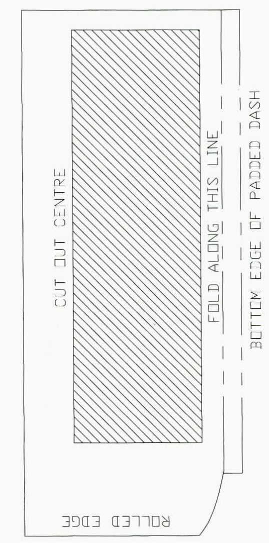
9 Locate wire assembly that plugged into the original blower switch. Cut all but the brown wire as far back as you can. Cut brown wire at the plug. Attach a male insulated spade connector. Locate the wire assembly that attached to the resistor. Cut the wires back as far as possible NOVA LOUVER INSTALL Locate the template provided. Cut out template and tape to the dash pad. Locate template along the bottom edge of padded dash. Locate left edge of template along crease in the dash pad. Carefully cut dash pad along opening in the template. LEFT EDGE 9


10 Locate in the hardware sack kit the center louver assembly and (2) pieces of 2 diameter flex duct 2ft long. 22 FLEX HOSE 18 FLEX HOSE Attach to the louvers as shown. BRACKET MUST TOUCH THE TOP Locate in the hardware sack kit the center bezel mounting bracket and (2) #10 x 5/8 pan head screws. Attach bracket through opening in the dash pad and attach to metal part of the instrument panel. Insert center louver assembly through opening and attach to bracket using (2) #10 x 5/8 pan head screws from the hardware sack kit 10


 pieces of 2 diameter flex duct 2ft long.")
11 1976 NOVA ONLY LOUVER INSTALL Locate the template provided. Cut out template and tape to the dash pad. Locate left edge of template along rolled edge in the dash pad as shown. Carefully cut dash pad along opening in the template as shown above. 24 FLEX HOSE 19 FLEX HOSE Locate in the hardware sack kit the center louver assembly and (2) pieces of 2 diameter flex duct 2ft long. Cut (1) piece of hose 19 long and (1) piece of hose 24 long. Attach to the louvers as shown. Insert center louver assembly through opening. 11
 piece of hose 19 long and (1) piece of hose 24 long.")

12 Locate the louver attachment bracket and (2) #8 x 3/8 pan head screws. Attach bracket to back of louver using (2) #8 x 3/8 pan head screws. Cut (1) piece of hose 19 long and (1) piece of hose 24 long. NOTE: DRIVERS AND PASSENGER LOUVERS ARE THE SAME FROM Locate template for the passenger side louver. Attach to right side of the glove box. Cut panel carefully to the line. It may be necessary to use a file to finish sizing the hole. Use the louver from the hardware sack kit to test fit. Locate 2 dia flex hose and (2) #8 x 3/8 pan head screw. Cut 42 of flex hose and attach to the passenger louver assembly. Set assembly aside for later installation. 12
 #8 x 3/8 pan head screw.")
 #10 x 5/8 pan head screws. Attach the defrost duct to the evaporator using the (2) screws.")
13 Locate drivers side louver template and carefully cut out the perimeter. Attach to the instrument cluster as shown. Cut panel carefully to the line. It may be necessary to use a file to finish sizing the hole. Use the louver from the hardware sack kit to test fit. Locate 48 of 2 dia flex hose and (2) #8 x 3/8 pan head screw. Attach 48 of flex hose and attach to the passenger louver assembly. Set assembly aside for later installation. All modifications to the vehicle are complete. We will now begin the installation of the System. Locate Evaporator, Defrost Duct Assembly, and (2) #10 x 5/8 pan head screws. Attach the defrost duct to the evaporator using the (2) screws. Be sure that s-clips on back of the duct are attached to the opening flange on the evaporator. ATTACHMENT SCREWS Locate electrical harness that is attached to the face door and connect to the micro switches. Refer to wiring diagram on the next page for correct connections. 13
14 14

 mounting brackets, (2) #10 x ¾ tek screws, and (4) #10 x 5/8 pan head screws.")
 tek screws.")
15 Place Evaporator assembly on passenger floor. Lift into place. ¼ 20 FLANGE NUT Insert upper rear Evaporator mounting stud through original hole as shown. Attach using (1) ¼ 20 flange nut provided. Locate in the hardware sack kit (2) mounting brackets, (2) #10 x ¾ tek screws, and (4) #10 x 5/8 pan head screws. Attach brackets to holes provided on front of the evaporator using the #10 pan head screws. Holding evaporator level with bottom of glove box opening attach to the body of the car using (2) tek screws. CAUTION: INSTALL SCREWS TO THE HOUSING USING A NON-POWERED SCREW DRIVER. Locate the Firewall Block Off plate, and (7) #10 x ¾ hex head tek screws. On engine side of firewall attach over hookup tubes from evaporator using (7) #10 x ¾ hex washer head Tek screws.. 15


 worn gear clamps as shown above.")
16 Route temperature cable across front of evaporator, down across the bottom next to blower and out the suction tube hole. Also locate blue clutch wire from the thermostat. Route over top of the unit and out thru hole with large pipe. Locate in the hardware sack kit (1) 3/8 nylon clamp, and (1) #8x ½ pan head screw. Attach clamp to temp cable and the evaporator using the #8 screw provided. Attach to the top pre drilled hole as shown. Locate the Water Valve and (3) worm gear clamps. Supply line from engine is attached to the upper heater hookup tube. Cut 6 off end of the return line and install water valve using (3) worn gear clamps as shown above. Locate temp cable and attach to the heater water valve. Be sure that the temp lever on control head is in the cold position. Note: It is recommended that you replace heater hoses from the engine to the hookup tubes. 16


 s-clips on the lip of defrost opening.")

17 Locate in the hardware sack kit (2) Defrost diffusers, 2 dia. flex hose. Cut the 2 flex hose 19 and 24. Attach these to the defrost diffusers using the #8 pan head screws. Locate defrost diffuser with the 24 flex hose and attach it behind the glove box opening so it lines up in middle of the defrost outlet. Attach using (2) s-clips on the lip of defrost opening. Locate defrost diffuser with the 19 flex hose and attach behind the instruments and in middle of the defrost outlet. Route flex hose over top and behind the unit bracket and over to right outlet on the defrost duct. Route flex hose from the drivers diffuser over to left outlet on the defrost duct. 17
 Original Blower Switch (3) Temp Cable (2) Heat Cable (4) Air Shutoff Cable Locate the blower switch assembly provided in kit.")
 Heat / Defrost control cable, (LONG) Temperature control cable, (2) 3/16 push nuts and (2) Cable Clips.")
 cable clip, (1) push nut, and the original screw.")
18 Locate the original control assembly. Remove and discard the following components. Retain all original hardware. (1) Original Blower Switch (3) Temp Cable (2) Heat Cable (4) Air Shutoff Cable Locate the blower switch assembly provided in kit. Attach Blower Switch assembly on to control head using the original hardware. Locate Connecting Wire and 3/16 push nut. Attach to switch and the center lever as shown. CONNECTING WIRE AND PUSH NUT Locate in the control sack kit the (SHORT) Heat / Defrost control cable, (LONG) Temperature control cable, (2) 3/16 push nuts and (2) Cable Clips. Rotate the control head upside down. Attach temperature control cable and clip to bottom lever arm using the original screw and 3/16 push nut. NOTE: Cable sleeve is located even with the cable clip. Attach the Heat / Defrost cable to control lever in the center. Using (1) cable clip, (1) push nut, and the original screw. NOTE: Cable sleeve located even with the cable clip. Attach Wire Harness supplied in unit to the blower switch. REFER TO THE WIRING DRAWING ON PAGE 11 FOR PROPER CONNECTIONS. 18
 to Red / White stripe wire from the new harness supplied.")
 #10 tek screw. Attach this terminal to the body.")
 blue wires at control end of the wire harness.")

19 NOTE: THE NEXT FEW STEPS ARE LOCATED BEHIND THE INSTRUMENT PANEL. Reinstall control head using the original hardware. Connect power wire (brown / from the original harness) to Red / White stripe wire from the new harness supplied. Route harness across top of the evaporator and connect to the resistor, motor and thermostat. Refer to the wiring diagram. Locate black wire with ring terminal from the blower motor and (1) #10 tek screw. Attach this terminal to the body. Locate ground wire from srevo motor harness and attach to the brace as shown. use (1) #10 tek screw. WIRE FROM ACTUATOR FROM T-STAT FROM CONTROLS Locate (2) blue wires at control end of the wire harness. Wire from the controls attaches to jumper connector on the micro switch. Wire from thermostat connects directly to the micro switch. Route shortest of the (2) cables and attach to the defrost / heat duct. Insert cable into first hole at the bottom of crank arm. #8 x 1/2 PAN HEAD SCREW Attach using (1) #8 x ½ pan head screw. 19


20 Locate the face duct assembly. Attach to the evaporator outlet using s-clips at top and bottom of the duct. Locate the drivers side louver. Insert through opening in the face bezel. Route flex hose over top of the steering column and over to center of the car. Locate the passenger side louver. Insert through hole in the dash. Route the flex hose over to center of the car. LEFT CENTER RIGHT CENTER Locate 2 Dia. flex hose from the left center louver adaptor. Attach to face duct over the left outlet. Locate 2 Dia. flex hose from the right center louver adaptor. Attach to face duct over the top outlet. 20


21 Locate 2 Dia. flex hose that was routed from driver louver and attach to the bottom outlet. Secure using (1) #8 x 3/8 pan head screw. Locate 2 flex hose that was routed from passenger louver assembly and attach to the right outlet. Secure using (1) #8 x 3/8 pan head screw. Reinstall the radio using original hardware. Locate the New Glove Box supplied in kit. Slide through opening as shown. Reinstall the glove box and door. Attach using original hardware. NOTE: Flex hose from the passenger louver routes above the glove box. GLOVE BOX MOUNTING Caution: Carefully check under the Instrument Panel for all cables, electrical harness, or Flex hose that might interfere with safe operation of the vehicle. Installation of the interior components is complete. We will now install the under hood portion of the system. 21
 holes.")
 HOLES Locate the Condenser, (2) top condenser mounting brackets, (2) bottom")

22 NOVA CONDENSER INSTALLATION Remove the hood latch assembly. Retain original hardware. Located on drivers side of radiator and on the radiator bulkhead. There are (2) holes. Locate and drill (1) 1 ½ dia hole, 1 ¾ above the top original hole. DRILL 1 ½ DIA. HOLE 1 ¾ ON CENTER ORIGINJAL (2) HOLES Locate the Condenser, (2) top condenser mounting brackets, (2) bottom condenser mounting brackets and (8) #10 x 3/8 hex head screws. Attach brackets to the condenser as shown. Place condenser on the bench with fittings to the left. Attach the lower mounting brackets to the bottom (2) holes using (4) #10 hex head screws. Tighten screws at bottom of the slots. 22


 5/16-18 x ½ hex head bolt and flat washer.")
23 Turn condenser over and attach top mounting brackets to the top holes using #10 hex head screws. Locate in the hardware sack kit (2) 5/16 j- clips. Attach over holes in the upper radiator bulkhead. Slide condenser assembly down in front of the radiator. Locate (2) 5/16-18 x ½ hex head bolt and flat washer. Attach top left bracket to the j-clip using 5/16 bolt and washer. 23

 #6 o-ring, 3/8 hose clamp, and (2) #10 tek screws.")

24 Locate the discharge tube, (1) #8 o-ring and (1) hole grommet. Install grommet over the tube as shown Attach tube to fitting on condenser using a few drops of mineral oil and the o-ring. Other end goes through the hole previously drilled Attach top right bracket to the j-clip using 5/16 bolt and washer. Locate the liquid tube, (1) #6 o-ring, 3/8 hose clamp, and (2) #10 tek screws. Attach looped end of the tube to lower condenser fitting using (1) #6 o-ring and a few drops of mineral oil. Other end will be attached to the lower condenser bracket using the 3/8 clamp and a #10 tek screw. Using other tek screw secure the right side lower condenser bracket. REINSTALL THE FRONT BUMPER AND HOOD LATCH ASSEMBLY USING ORIGINAL HARDWARE. 24


25 1976 NOVA CONDENSER INSTALLATION INSTALL THE COMPRESSOR ADAPTER KIT AND COMPRESSOR AT THIS TIME PER THE MANUFACTURERS DIRECTIONS. Remove and retain the 4 hood latch mounting bolts as shown. Remove and retain the 2 lower hood latch support bolts, and remove hood latch assembly. Remove and retain the 2 screws on driver side headlight that mount the grill assembly. Remove and retain the 2 screws on passenger side headlight and remove and retain the grill assembly. 25


26 Locate the templet supplied in instructions, and cut out along dotted line and tape it to the radiator cowl as shown, and using a hole saw cut a 1 1/8 hole. Locate the 1 grommet supplied in kit and install it into the hole as shown. Locate the (4) condenser mounting brackets supplied in kit, and (8) #8 x 3/8 screws, and attach the brackets to condenser as shown above. Note the lower bracket will be slid all the way up and then tightened. 26


 9/32 hole as")
27 Use this O.E. hole on the passenger side radiator cowl, as a locator for the top passenger side bracket when installing the condenser. Place condenser assembly inside radiator cowl to the drivers side, then slide condenser to the passenger side so the top condenser fitting will go through the grommet, and the top left bracket aligns with the O.E. hole as shown above. After installing condenser assembly, and aligning the top left bracket with the O.E. hole, use the top right bracket as a templet and drill (1) 9/32 hole as shown. Attach the top condenser brackets to the radiator cowl using (2) ¼-20 x 5/8 bolts and (2) ¼-20 nuts as shown. 27
 #10 x ¾ Tek screws as")


 #10 x ¾ Tek screws as")
28 Attach the two bottom brackets to the lower radiator cowl using (2) #10 x ¾ Tek screws as shown above. Attach short liquid hose to drier and evaporator so the drier is in a straight line with the hose. Install drier clamp to drier and attach to fenderwell using (2) #10 x ¾ Tek screws as shown. Route the long #6 hose through the fenderwell and behind the battery tray as shown. 28
 #6 o-ring and a few drops of")
 #6")

29 Attach the #6 hose with the 45 deg. Fitting to the bottom fitting of the condenser, using (1) #6 o-ring and a few drops of mineral oil and tighten fitting. Attach the #6 hose with the straight Fitting to the IN side of the drier, using (1) #6 o-ring and a few drops of mineral oil and tighten fitting. Route the #8 hose through the fenderwell and behind the battery tray as shown. Attach the #8 hose with the straight Fitting to the top of the condenser, using (1) #8 o-ring and a few drops of mineral oil and tighten fitting. 29
 #8 o-ring and a few drops of mineral")
 #10 o- ring and a")

30 Installation for 250CID 6 CYL shown. Refer to V8 install. Attach the #8 hose with the 90 deg Fitting to the compressor, using (1) #8 o-ring and a few drops of mineral oil and tighten fitting. Attach the #10 hose with the straight Fitting with service port to the compressor, using (1) #10 o- ring and a few drops of mineral oil, and attach the other end of the #10 hose to the evaporator as shown using (1) #10 o-ring and a few drops of mineral oil and tighten fitting. REINSTALL GRILL AND HOOD LATCH USING ORIGINAL HARDWARE. OPTIONAL 18 6 BLADE FAN REQUIRED Vehicles not equipped with a heavy duty fan, require a 5-6 blade fan for maximum performance. 30

 #8 o-ring and a few drops of mineral oil. Attach other end to fitting from the condenser. Tighten securely.")

31 NOVA INSTALL THE COMPRESSOR ADAPTER KIT AND COMPRESSOR AT THIS TIME PER THE MANUFACTURERS DIRECTIONS. NOTE: THIS INSTALL IS CORRECT FOR A 350CID V8 ENGINE, WITH ALTERNATOR ON PASSENGER SIDE OF VEHICLE. IF YOUR VEHICLE IS EQUIPTED WITH A DIFFERENT ENGINE PACKAGE IT WILL BE NECESSARY TO ROUTE THE HOSES DIFFERENT Locate the Discharge hose and (1) #8 o-ring. Attach #8 refrigerant hose with service port end to the compressor using (1) #8 o-ring and a few drops of mineral oil. Attach other end to fitting from the condenser. Tighten securely. Locate the suction hose and (2) #10 o-rings. Attach end with service port to the compressor as shown above. LIQUID HOSE Route hose over the radiator hose, across engine and over to #10 fitting on the firewall. RECEIVER / PRESSURE SWITCH Attach both ends using the #10 o-rings and a few drops of mineral oil. Locate the Filter / Drier, Drier Mounting Bracket, liquid hose (short), (2) #6 o-rings and (2) #10 x 3/4 hex head tek screws. Install Filter drier to the inner fender well as shown. Install #6 liquid hose between firewall and the drier. Use a few drops of mineral oil on the o-ring and fittings, tighten securely. Locate Hi-Low pressure switch and attach to the top of the receiver drier using a few drops of mineral oil. 31


32 Locate the liquid hose (long), and (2) #6 o-ring. RADIATOR Attach one end to the drier. Route other end along inner fender and down to the condenser fitting. Attach using #6 o- ring and a few drops of mineral oil. Locate the remaining clamps and screws. Attach hoses to the alternator bracket and the inner fender well. THE ENGINE COMPARTMENT OF YOUR SYSTEM IS COMPLETE. THE UNIT IS READY FOR EVACUATION AND CHARGING. THIS SHOULD BE DONE BY A QUALIFIED AND CERTIFIED AIR CONDITIONING TECHNICIAN. NOTE: COMPRESSOR IS SUPPLIED WITH THE CORRECT OIL CHARGE. DO NOT ADD OIL TO SYSTEM. 134A SYSTEMS 24 oz OF REFRIGERANT Recommend that power fuse is 25amp minimum Congratulations you have completed the install of your CLASSIC AUTO AIR PERFECT FIT SERIES climate control system. 32
33 IMPORTANT CAUTION: WATER VALVE MUST BE INSTALLED PER THE INSTRUCTIONS. Classic Auto Air has done extensive testing on the correct method to install the water valve in order to get a repeatable and progressive temperature control. Locate the bottom connection from the evaporator/heater unit off of the firewall and attach a 6 piece of 5/8 dia. heater hose with the supplied hose clamp. Next attach the inlet side of the water valve using another supplied hose clamp, (make sure the arrow on the water valve points toward the engine) Attach a heater hose from the outlet side of the water valve and route to the connection on the water pump. NOTE: WATER VALVE = WATER PUMP FROM HEATER CORE TO WATER PUMP COOLANT FLOW CAUTION: WATER VALVE MUST BE INSTALLED ON HEATER LINE ROUTED TO WATER PUMP. NOTE: COMPRESSOR PURCHASED WITH KIT IS SUPPLIED WITH THE CORRECT OIL CHARGE. DO NOT ADD OIL TO SYSTEM. 134A SYSTEMS 24 oz OF REFRIGERANT Recommend that power fuse is 25amp minimum 33
34 NOVA 34
35 35
36 36
37 37
38 38
39 39
40 40
41 41
PERFECT FIT SERIES IN-DASH HEAT/ COOL/ DEFROST 1969 CHEVROLET CAMARO/ FIREBIRD NOTE: INSTRUCTIONS DEPICT CAMARO
 specializing in AIR CONDITIONING, PARTS AND SYSTEMS for your classic vehicle PERFECT FIT SERIES IN-DASH HEAT/ COOL/ DEFROST 1969 CHEVROLET CAMARO/ FIREBIRD NOTE: INSTRUCTIONS DEPICT CAMARO CONTROL & OPERATING
PERFECT FIT SERIES IN-DASH HEAT/ COOL/ DEFROST MUSTANG
 specializing in AIR CONDITIONING, PARTS AND SYSTEMS for your classic vehicle PERFECT FIT SERIES IN-DASH HEAT/ COOL/ DEFROST 1969-70 MUSTANG CONTROL & OPERATING INSTRUCTIONS The controls on your new Perfect
PERFECT FIT IN-DASH HEAT/ COOL/ DEFROST FORD FAIRLANE & CROWN VICTORIA
 PERFECT FIT IN-DASH HEAT/ COOL/ DEFROST 1955-56 FORD FAIRLANE & CROWN VICTORIA CONTROL & OPERATING INSTRUCTIONS The controls on your new Perfect Fit system, offer complete comfort capabilities in virtually
CHEVROLET CORVETTE
 Suggested Installation Instructions for: 658-133 and 658-134 1968-1976 Air Conditioning Retro-Fit System 1968-76 CHEVROLET CORVETTE CONTROL & OPERATING INSTRUCTIONS The controls on your new Perfect Fit
FACTORY AIR CONVERSION HEAT/ COOL/ DEFROST CHEVROLET CHEVELLE
 specializing in AIR CONDITIONING, PARTS AND SYSTEMS for your classic vehicle FACTORY AIR CONVERSION HEAT/ COOL/ DEFROST 1970-72 CHEVROLET CHEVELLE CONTROL & OPERATING INSTRUCTIONS The controls on your
HEAT/ COOL/ DEFROST CHEVROLET PICKUP CONTROL & OPERATING INSTRUCTIONS
 specializing in AIR CONDITIONING, PARTS AND SYSTEMS for your classic vehicle PERFECT FIT FACTORY AIR CONVERSION HEAT/ COOL/ DEFROST 1967-72 CHEVROLET PICKUP CONTROL & OPERATING INSTRUCTIONS The controls
Installation Manual PERFECT FIT Mustang Factory Air SERIES. Elite DOCUMENT #1-2026FA ClassicAutoAir / 6.11vs1
 PERFECT FIT SERIES Elite Installation Manual 1967-1968 Mustang Factory Air DOCUMENT #1-2026FA 2011 ClassicAutoAir / 6.11vs1 Congratulations... You have just purchased the highest quality, best performing
1963 GEN IV SUREFIT VINTAGE AIR CONDITIONING INSTALLATION
 by Randy Irwin 1963 GEN IV SUREFIT VINTAGE AIR CONDITIONING INSTALLATION Randy Irwin - Technical Writer Randy has been involved in the Chevy parts business for over 30 years. He is a wizard at creating,
Chevrolet Truck Install Instructions. This kit is designed for the Chevrolet or GMC trucks without factory air conditioning.
 1967-1972 Chevrolet Truck Install Instructions This kit is designed for the 1967-1972 Chevrolet or GMC trucks without factory air conditioning. Glove box Heater box Heater box firewall cover Controls and
1. Disconnect the battery. This is important! This will prevent air bag deployment.
 PARTS PACKING LIST Evaporator assembly Drain tube Plastic air plug Hardware package 11040 3601 W. Clarendon Phoenix, Arizona 85019 (602) 233-0090 800-648-4475 www.ackits.com 2003-4 Jeep Wrangler EVAPORATOR
Ford F-100 Evaporator Kit (751153)
") an ISO 9001:2015 Registered Company 1968-72 Ford F-100 Evaporator Kit (751153) 18865 Goll St. San Antonio, TX 78266 Phone: 800-862-6658 Sales: sales@vintageair.com Tech Support: tech@vintageair.com www.vintageair.com
an ISO 9001:2015 Registered Company 1968-72 Ford F-100 Evaporator Kit (751153) 18865 Goll St. San Antonio, TX 78266 Phone: 800-862-6658 Sales: sales@vintageair.com Tech Support: tech@vintageair.com www.vintageair.com
1969 CAMARO VCZ-A
 969 CAMARO w/o FACTORY AIR 55070-VCZ-A 8865 GOLL ST. - SAN ANTONIO, TX. - 78266 ph.20-654-77 - fax 20-654-33 905070-VCZ-A /22/05, 69 CAMARO w/o FAC. AIR INSTRUCTIONS PG OF 20 969 CAMARO w/o FACTORY AIR
Installation Manual Mustang DOCUMENT # ClassicAutoAir / 2.12vs3
 Installation Manual 1969-1970 Mustang DOCUMENT #1-2027 2012 ClassicAutoAir / 2.12vs3 Congratulations... You have just purchased the highest quality, best performing A/C system ever designed for your Classic
Installation Manual Mustang Factory Air DOCUMENT #1-2026FA ClassicAutoAir / vs2.12
 Installation Manual 1967-1968 Mustang Factory Air DOCUMENT #1-2026FA 2012 ClassicAutoAir / vs2.12 Congratulations... You have just purchased the highest quality, best performing A/C system ever designed
Installation Manual Mustang
 Installation Manual 1967-1968 Mustang DOCUMENT #1-2026 2013 ClassicAutoAir / 7.13vs4 3 You have just purchased the highest quality, best performing A/C system ever designed for your Mustang. To obtain
Jeep Wrangler TJ 4.0 LITER Installation instructions
 www.jeepair.com 2002-2004 Jeep Wrangler TJ 4.0 LITER Installation instructions Kit Information These directions are for 2002-2006 model Jeep Wranglers. After 1994 every vehicle was designed for R134a refrigerant.
1967 Ford F-100 Evaporator Kit (751152)
") an ISO 9001:2015 Registered Company 1967 Ford F-100 Evaporator Kit (751152) 18865 Goll St. San Antonio, TX 78266 Phone: 800-862-6658 Sales: sales@vintageair.com Tech Support: tech@vintageair.com www.vintageair.com
an ISO 9001:2015 Registered Company 1967 Ford F-100 Evaporator Kit (751152) 18865 Goll St. San Antonio, TX 78266 Phone: 800-862-6658 Sales: sales@vintageair.com Tech Support: tech@vintageair.com www.vintageair.com
Rzr Heater System Part #
 Rzr Heater System Part # 2878135 NOTE: This heater unit installs below the center of the dash. If you have a radio mount kit (Polaris Part # 2876897) you may need to cut the top front corner off the mount
Jeep Wrangler 4.0 Liter TJ Jeep Wrangler 2.5 Liter TJ Installation instructions
 TM www.jeepair.com 1999 Jeep Wrangler 4.0 Liter TJ 1999-2001 Jeep Wrangler 2.5 Liter TJ Installation instructions Kit Information After 1994 every vehicle was designed for R134a refrigerant. The Jeep kit
an ISO 9001: 2008 Registered Company CHEVELLE without FACTORY AIR REV C 8/27/14, CHEVELLE wo AC EVAP INSTR PG 1 OF 29
 an ISO 9001: 2008 Registered Company 1966-67 CHEVELLE without FACTORY AIR 561066 SS 901162 REV C 8/27/14, 1966-67 CHEVELLE wo AC EVAP INSTR PG 1 OF 29 PAGES Table of Contents 1. COVER 2. TABLE OF CONTENTS
CHEVROLET PICKUP
 an ISO 9001:2008 Registered Company 1973-80 CHEVROLET PICKUP with FACTORY AIR 754175 904184 REV C 1/19/15, INST 73-80 CHEV P-UP w/ AC EVAP KIT PG 1 OF 27 Table of Contents PAGES 1. COVER 2. TABLE OF CONTENTS
Chevrolet Full-Size/El Camino with 2-Lever Controls
 an ISO 9001:2008 Registered Company 1959-60 Chevrolet Full-Size/El Camino with 2-Lever Controls 561055 18865 Goll St. San Antonio, TX 78266 ph: 210-654-7171 fax: 210-654-3113 901116 REV B 7/21/14, INST
Chevrolet Camaro without Factory Air Evaporator Kit (561180)
") an ISO 9001:2008 Registered Company 1979-81 Chevrolet Camaro without Factory Air Evaporator Kit (561180) 18865 Goll St. San Antonio, TX 78266 Phone: 210-654-7171 Fax: 210-654-3113 901186 REV D 01/13/17,
an ISO 9001:2008 Registered Company 1979-81 Chevrolet Camaro without Factory Air Evaporator Kit (561180) 18865 Goll St. San Antonio, TX 78266 Phone: 210-654-7171 Fax: 210-654-3113 901186 REV D 01/13/17,
an ISO 9001: 2008 Registered Company NOVA WITH AC REV C 7/16/14, NOVA w/ AC EVAP INST PG 1 OF 25
 an ISO 9001: 2008 Registered Company 1969-72 NOVA WITH AC 565072 905073 REV C 7/16/14, 1969-72 NOVA w/ AC EVAP INST PG 1 OF 25 Table of Contents PAGES 1. COVER 2. TABLE OF CONTENTS 3. PACKING LIST / PARTS
Jeep Wrangler TJ. Complete Air Conditioning System. Slide Control Head. Installation instructions
 WWW.JEEPAIR.COM 1996-1998 Jeep Wrangler TJ Complete Air Conditioning System Slide Control Head Installation instructions Kit Information After 1994 every vehicle was designed for R134a refrigerant. The
Chevrolet Impala with Factory Air Evaporator Kit (564062)
") an ISO 9001:2015 Registered Company 1961-62 Chevrolet Impala with Factory Air Evaporator Kit (564062) 18865 Goll St. San Antonio, TX 78266 Phone: 800-862-6658 Sales: sales@vintageair.com Tech Support:
an ISO 9001:2015 Registered Company 1961-62 Chevrolet Impala with Factory Air Evaporator Kit (564062) 18865 Goll St. San Antonio, TX 78266 Phone: 800-862-6658 Sales: sales@vintageair.com Tech Support:
Cutlass without Factory Air
 an ISO 9001: 2008 Registered Company 1970-72 Cutlass without Factory Air 561076 18865 Goll St. San Antonio, TX 78266 ph: 210-654-7171 fax: 210-654-3113 901076 REV A 9/17/12, INST 1970-72 CUTLASS wo AC
Chevrolet Nova without Factory Air Evaporator Kit (561072)
") an ISO 9001: 2015 Registered Company 1969-72 Chevrolet Nova without Factory Air Evaporator Kit (561072) 18865 Goll St. San Antonio, TX 78266 Phone: 800-862-6658 Sales: sales@vintageair.com Tech Support:
an ISO 9001: 2015 Registered Company 1969-72 Chevrolet Nova without Factory Air Evaporator Kit (561072) 18865 Goll St. San Antonio, TX 78266 Phone: 800-862-6658 Sales: sales@vintageair.com Tech Support:
1964 ½ TO 66 MUSTANG
 an ISO 9001: 2008 Registered Company 1964 ½ TO 66 MUSTANG with & without A/C 554164 904163 REV E 1/19/15, 1964 1/2-66 MUSTANG EVAP INSTR PG 1 OF 29 Table of Contents PAGES 1. COVER 2. TABLE OF CONTENTS
1969 Chevrolet Camaro without Factory Air Evaporator Kit (561169)
") an ISO 9001:2008 Registered Company 1969 Chevrolet Camaro without Factory Air Evaporator Kit (561169) 18865 Goll St. San Antonio, TX 78266 Phone: 210-654-7171 Fax: 210-654-3113 901169 REV E 01/13/17, PG
an ISO 9001:2008 Registered Company 1969 Chevrolet Camaro without Factory Air Evaporator Kit (561169) 18865 Goll St. San Antonio, TX 78266 Phone: 210-654-7171 Fax: 210-654-3113 901169 REV E 01/13/17, PG
Camaro without Factory Air
 1970-78 Camaro without Factory Air 561173 No. Qty. Part No. Description 1. 2. 1 1 744004-VUE 781178 Packing List Evaporator Kit (561173) 4-Vent Evap orator Sub Case w/ 204 ECU Accessory Kit 1970-78 Camaro
CHEVROLET PICKUP
 an ISO 9001:2008 Registered Company 1981-87 CHEVROLET PICKUP WITHOUT FACTORY AIR 751181 901182 REV B 7/22/14, INST 81-87 CHEV P-UP wo AC EVAP KIT PG 1 OF 27 Table of Contents PAGES 1. COVER 2. TABLE OF
CAMARO WITHOUT FACTORY AIR
 1967-68 CAMARO WITHOUT FACTORY AIR 561167 OFF COLD OFF FLR ON HOT DE-ICE 1. 2. EVAPORATOR KIT PACKING LIST NO. QTY. PART NO. DESCRIPTION 1 1 744005 781168 GEN IV 3 VENT EVAP. SUB CASE w/ 204 ECU 1967-68
an ISO 9001: 2008 Registered Company NOVA WITHOUT AC REV C 7/18/ NOVA wo AC EVAP INSTR PG 1 OF 24
 an ISO 9001: 2008 Registered Company 1969-72 NOVA WITHOUT AC 561072 901179 REV C 7/18/14 1969-72 NOVA wo AC EVAP INSTR PG 1 OF 24 Table of Contents PAGES 1. COVER 2. TABLE OF CONTENTS 3. PACKING LIST /
WOC-364 Installation Instructions Ranger XP Heater System
 WOC-364 Installation Instructions Ranger 2011-12 XP Heater System Order of installation for a Complete Enclosure Always install the Heater System first if possible NOTE: If installing the Heater System
Ford Falcon, Ranchero Evaporator Kit (554150)
") an ISO 9001:2008 Registered Company 1964-65 Ford Falcon, Ranchero Evaporator Kit (554150) 18865 Goll St. San Antonio, TX 78266 Phone: 210-654-7171 Fax: 210-654-3113 www.vintageair.com 905140 REV A 06/23/15,
an ISO 9001:2008 Registered Company 1964-65 Ford Falcon, Ranchero Evaporator Kit (554150) 18865 Goll St. San Antonio, TX 78266 Phone: 210-654-7171 Fax: 210-654-3113 www.vintageair.com 905140 REV A 06/23/15,
Dodge Charger, Coronet Evaporator Kit with Factory Air
 an ISO 9001:2008 Registered Company 1966-67 Dodge Charger, Coronet Evaporator Kit with Factory Air 571067 18865 Goll St. San Antonio, TX 78266 Phone: 210-654-7171 Fax: 210-654-3113 www.vintageair.com 901313
1969 Firebird with Factory Air
 an ISO 9001:2008 Registered Company 1969 Firebird with Factory Air 564468 18865 Goll St. San Antonio, TX 78266 ph: 210-654-7171 fax: 210-654-3113 901124 REV B 7/14/14, INST 69 FIREBIRD w/ A/C EVAP KIT
ARTICLE BEGINNING * PLEASE READ THIS FIRST * DESCRIPTION OPERATION ATC COMPUTER BLEND-AIR DOOR ACTUATOR CONTROL PANEL
 A/C-HEATER SYSTEM - AUTOMATIC Article Text 1989 Chrysler LeBaron Sedan For m m m m m Copyright 1998 Mitchell Repair Information Company, LLC Thursday, July 03, 2003 10:15AM ARTICLE BEGINNING 1989 AUTOMATIC
1964 ½-66 Ford Mustang Evaporator Kit (554164)
") an ISO 9001:2008 Registered Company 1964 ½-66 Ford Mustang Evaporator Kit (554164) 18865 Goll St. San Antonio, TX 78266 Phone: 210-654-7171 Fax: 210-654-3113 www.vintageair.com 904163 REV F 11/11/16, PG
an ISO 9001:2008 Registered Company 1964 ½-66 Ford Mustang Evaporator Kit (554164) 18865 Goll St. San Antonio, TX 78266 Phone: 210-654-7171 Fax: 210-654-3113 www.vintageair.com 904163 REV F 11/11/16, PG
an ISO 9001:2008 Registered Company CAMARO WITHOUT FACTORY AIR REV C 8/13/ CAMARO w/o AC EVAP INST PG 1 OF 32
 an ISO 9001:2008 Registered Company 1967-68 CAMARO WITHOUT FACTORY AIR 561167 901167 REV C 8/13/14 67-68 CAMARO w/o AC EVAP INST PG 1 OF 32 PAGES Table of Contents 1. COVER 2. TABLE OF CONTENTS 3. PACKING
1969 Firebird without Factory Air
 an ISO 9001:2008 Registered Company 1969 Firebird without Factory Air 561168 18865 Goll St. San Antonio, TX 78266 ph: 210-654-7171 fax: 210-654-3113 901125 REV B 7/14/14, INST 69 FIREBIRD wo AC EVAP KIT
1964 Chevrolet Impala without Factory Air Evaporator Kit (561064)
") an ISO 9001:2008 Registered Company 1964 Chevrolet Impala without Factory Air Evaporator Kit (561064) 18865 Goll St. San Antonio, TX 78266 Phone: 210-654-7171 Fax: 210-654-3113 www.vintageair.com 903061
an ISO 9001:2008 Registered Company 1964 Chevrolet Impala without Factory Air Evaporator Kit (561064) 18865 Goll St. San Antonio, TX 78266 Phone: 210-654-7171 Fax: 210-654-3113 www.vintageair.com 903061
Jeep Wrangler TJ 4.0 LITER Installation instructions
 www.jeepair.com 2000-2001 Jeep Wrangler TJ 4.0 LITER Installation instructions Important information about your system, and warranty DO NOT ADD ANY OIL TO ANY PART OF THE SYSTEM. DO NOT USE THE SIGHT GLASS
Mopar B-Body Evaporator Kit with Factory Air
 an ISO 9001:2008 Registered Company 1969-70 Mopar B-Body Evaporator Kit with Factory Air 571065 Fits: Dodge: Coronet, Super Bee, Charger Plymouth: Satellite, Road Runner, GTX 18865 Goll St. San Antonio,
1968 Mopar B-Body without Factory Air Evaporator Kit
 an ISO 9001:2008 Registered Company 1968 Mopar B-Body without Factory Air Evaporator Kit 571062 Fits: Dodge: Coronet, Super Bee, Charger Plymouth: Satellite, Road Runner, GTX 18865 Goll St. San Antonio,
an ISO 9001: 2008 Registered Company CHEVELLE without FACTORY AIR REV B 7/15/14, CHEVELLE w/o AC EVAP INSTR PG 1 OF 26
 an ISO 9001: 2008 Registered Company 1968-69 CHEVELLE without FACTORY AIR 561068 901166 REV B 7/15/14, EVAP INSTR PG 1 OF 26 PAGES Table of Contents 1. COVER 2. TABLE OF CONTENTS 3. PACKING LIST/PARTS
Cutlass with Factory Air
 an ISO 9001: 2008 Registered Company 1968-69 Cutlass with Factory Air 564069 18865 Goll St. San Antonio, TX 78266 ph: 210-654-7171 fax: 210-654-3113 904057 REV B 10/2/12, INST 1968-69 CUTLASS w/ AC EVAP
Chevrolet Camaro with Factory Air Evaporator Kit (564167)
") an ISO 9001:2008 Registered Company 1967-68 Chevrolet Camaro with Factory Air Evaporator Kit (564167) 18865 Goll St. San Antonio, TX 78266 Phone: 800-862-6658 Sales: sales@vintageair.com Tech Support:
an ISO 9001:2008 Registered Company 1967-68 Chevrolet Camaro with Factory Air Evaporator Kit (564167) 18865 Goll St. San Antonio, TX 78266 Phone: 800-862-6658 Sales: sales@vintageair.com Tech Support:
Chevrolet Corvette with Factory Air Evaporator Kit (564174)
") an ISO 9001:2015 Registered Company 1974-76 Chevrolet Corvette with Factory Air Evaporator Kit (564174) 18865 Goll St. San Antonio, TX 78266 Phone: 800-862-6658 Sales: sales@vintageair.com Tech Support:
an ISO 9001:2015 Registered Company 1974-76 Chevrolet Corvette with Factory Air Evaporator Kit (564174) 18865 Goll St. San Antonio, TX 78266 Phone: 800-862-6658 Sales: sales@vintageair.com Tech Support:
1969 Pontiac Firebird with Factory Air Evaporator Kit
 an ISO 9001:2015 Registered Company 1969 Pontiac Firebird with Factory Air Evaporator Kit 564468 18865 Goll St. San Antonio, TX 78266 Phone: 800-862-6658 Sales: sales@vintageair.com Tech Support: tech@vintageair.com
Ford Bronco Evaporator Kit
 an ISO 9001:2008 Registered Company 1966-77 Ford Bronco Evaporator Kit 751150 18865 Goll St. San Antonio, TX 78266 ph: 210-654-7171 fax: 210-654-3113 908174 REV C 10/08/14, INST 66-77 FORD BRONCO EVAP
Ford Mustang Mercury Cougar without Factory Air Evaporator Kit (551168)
") an ISO 9001:2008 Registered Company 1967-68 Ford Mustang Mercury Cougar without Factory Air Evaporator Kit (551168) F O R D 18865 Goll St. San Antonio, TX 78266 Phone: 210-654-7171 Fax: 210-654-3113 www.vintageair.com
an ISO 9001:2008 Registered Company 1967-68 Ford Mustang Mercury Cougar without Factory Air Evaporator Kit (551168) F O R D 18865 Goll St. San Antonio, TX 78266 Phone: 210-654-7171 Fax: 210-654-3113 www.vintageair.com
RAINGEAR 1955/ 1956 Chevrolet
 RAINGEAR 1955/ 1956 Chevrolet GETTING STARTED: SOME RECOMMENDATIONS PLEASE TRY OUR WAY FIRST! Note: This system is designed with built in adjustments to fit in your car. If, as you are installing it, you
an ISO 9001:2008 Registered Company 1969 CAMARO with FACTORY AIR REV C 8/04/14, 69 CAMARO w/ AC EVAP INSTR PG 1 OF 26
 an ISO 9001:2008 Registered Company 1969 CAMARO with FACTORY AIR 564169 904169 REV C 8/04/14, 69 CAMARO w/ AC EVAP INSTR PG 1 OF 26 Table of Contents PAGES 1. COVER 2. TABLE OF CONTENTS 3. PACKING LIST/PARTS
Chevy Pickup without Factory Air
 an ISO 9001:2008 Registered Company 1967-72 Chevy Pickup without Factory Air 751170 18865 Goll St. San Antonio, TX 78266 ph: 210-654-7171 fax: 210-654-3113 901149 REV D 7/30/14, INST 67-72 CHEVY PICKUP
Ford Mustang, Mercury Cougar with Factory Air Evaporator Kit (554168)
") an ISO 9001:2008 Registered Company 1967-68 Ford Mustang, Mercury Cougar with Factory Air Evaporator Kit (554168) F O R D 18865 Goll St. San Antonio, TX 78266 Phone: 210-654-7171 Fax: 210-654-3113 904178
an ISO 9001:2008 Registered Company 1967-68 Ford Mustang, Mercury Cougar with Factory Air Evaporator Kit (554168) F O R D 18865 Goll St. San Antonio, TX 78266 Phone: 210-654-7171 Fax: 210-654-3113 904178
INSTALLATION INSTRUCTIONS 97 FORD EXPEDITION
 INSTALLATION INSTRUCTIONS 97 FORD EXPEDITION 1. Read the instructions completely and carefully before you begin. Check the kit for proper contents (refer to the part s list and the picture diagrams). Before
1969 Chevrolet Chevelle Condenser Kit with Drier (021168)
") an ISO 900:008 Registered Company 969 Chevrolet Chevelle Condenser Kit with Drier (068) 8865 Goll St. San Antonio, TX 7866 Phone: 0-654-77 Fax: 0-654-33 www.vintageair.com 90368 REV B 09/0/5, PG OF 6 Table
an ISO 900:008 Registered Company 969 Chevrolet Chevelle Condenser Kit with Drier (068) 8865 Goll St. San Antonio, TX 7866 Phone: 0-654-77 Fax: 0-654-33 www.vintageair.com 90368 REV B 09/0/5, PG OF 6 Table
1969 Chevrolet Camaro with Factory Air Evaporator Kit (564169)
") an ISO 9001:2008 Registered Company 1969 Chevrolet Camaro with Factory Air Evaporator Kit (564169) 18865 Goll St. San Antonio, TX 78266 Phone: 210-654-7171 Fax: 210-654-3113 904169 REV E 01/13/17, PG 1
an ISO 9001:2008 Registered Company 1969 Chevrolet Camaro with Factory Air Evaporator Kit (564169) 18865 Goll St. San Antonio, TX 78266 Phone: 210-654-7171 Fax: 210-654-3113 904169 REV E 01/13/17, PG 1
Chevrolet Corvette without Factory Air Evaporator Kit ( PCZ)
") an ISO 9001:2015 Registered Company 1968-76 Chevrolet Corvette without Factory Air Evaporator Kit (561174-PCZ) 18865 Goll St. San Antonio, TX 78266 Phone: 800-862-6658 Sales: sales@vintageair.com Tech
an ISO 9001:2015 Registered Company 1968-76 Chevrolet Corvette without Factory Air Evaporator Kit (561174-PCZ) 18865 Goll St. San Antonio, TX 78266 Phone: 800-862-6658 Sales: sales@vintageair.com Tech
Chevrolet Chevelle with Factory Air Evaporator Kit (565071)
") an ISO 9001:2015 Registered Company 1970-72 Chevrolet Chevelle with Factory Air Evaporator Kit (565071) SS 18865 Goll St. San Antonio, TX 78266 Phone: 800-862-6658 Sales: sales@vintageair.com Tech Support:
an ISO 9001:2015 Registered Company 1970-72 Chevrolet Chevelle with Factory Air Evaporator Kit (565071) SS 18865 Goll St. San Antonio, TX 78266 Phone: 800-862-6658 Sales: sales@vintageair.com Tech Support:
Chevrolet Corvette Condenser Kit with Drier ( CCA)
") an ISO 900:2008 Registered Company 969-72 Chevrolet Corvette Condenser Kit with Drier (02069-CCA) 8865 Goll St. San Antonio, TX 78266 Phone: 20-654-77 Fax: 20-654-33 www.vintageair.com 90069-CCA REV C
an ISO 900:2008 Registered Company 969-72 Chevrolet Corvette Condenser Kit with Drier (02069-CCA) 8865 Goll St. San Antonio, TX 78266 Phone: 20-654-77 Fax: 20-654-33 www.vintageair.com 90069-CCA REV C
1964 Chevrolet Impala Condenser Kit with Drier (021063)
") an ISO 900:2008 Registered Company 964 Chevrolet Impala Condenser Kit with Drier (02063) 8865 Goll St. San Antonio, TX 78266 Phone: 20-654-77 Fax: 20-654-33 www.vintageair.com 9036 REV B 03/0/6, PG OF
an ISO 900:2008 Registered Company 964 Chevrolet Impala Condenser Kit with Drier (02063) 8865 Goll St. San Antonio, TX 78266 Phone: 20-654-77 Fax: 20-654-33 www.vintageair.com 9036 REV B 03/0/6, PG OF
FORD MUSTANG, MERCURY COUGAR WITH FACTORY AIR EVAPORATOR KIT
 an ISO 9001: 2008 Registered Company 1967-68 FORD MUSTANG, MERCURY COUGAR WITH FACTORY AIR EVAPORATOR KIT 554168 F O R D 904178 REV E 4/8/16, 1967-68 MUSTANG/COUGAR w/ AC EVAP INSTR PG 1 OF 23 Table of
an ISO 9001:2008 Registered Company CAMARO WITH FACTORY AIR REV D 11/10/15, CAMARO w/ AC EVAP INST PG 1 OF 26
 an ISO 9001:2008 Registered Company 1967-68 CAMARO WITH FACTORY AIR 564167 904167 REV D 11/10/15, 1967-68 CAMARO w/ AC EVAP INST PG 1 OF 26 Table of Contents PAGES 1. COVER 2. TABLE OF CONTENTS 3. PACKING
A/C-HEATER SYSTEM - AUTOMATIC
 A/C-HEATER SYSTEM - AUTOMATIC 1988 Toyota Celica 1988 Automatic A/C-Heater Systems Celica * PLEASE READ THIS FIRST * CAUTION: When discharging air conditioning system, use only approved refrigerant recovery/recycling
RetroAir JAGUAR XKE S1-3.8 LHD FULL KIT CONTENTS:
 RetroAir JAGUAR XKE S1-3.8 LHD FULL KIT 2-12-2011 CONTENTS: 1- Custom Design Evaporator Case &Core Assembly 1- Universal Bracket (installed) Evaporator Pak includes: 2-Custom Brackets; 2-1-¼ Grommets;
1956 Ford Passenger Car Control Panel Conversion Kit (473150)
") an ISO 900:2008 Registered Company 956 Ford Passenger Car Control Panel Conversion Kit (47350) 8865 Goll St. San Antonio, TX 78266 Phone: 20-654-77 Fax: 20-654-33 www.vintageair.com 900505 REV B 04/4/5,
an ISO 900:2008 Registered Company 956 Ford Passenger Car Control Panel Conversion Kit (47350) 8865 Goll St. San Antonio, TX 78266 Phone: 20-654-77 Fax: 20-654-33 www.vintageair.com 900505 REV B 04/4/5,
WPS-104 Heater Installation Instructions For 500EFI, 700 XP, & Crew Applications
 WPS-104 Heater Installation Instructions For 500EFI, 700 XP, & Crew Applications ORDER OF INSTALLATION FOR A COMPLETE ENCLOSURE OF A RANGERWARE WPS (Weather Protection System) IS AS FOLLOWS: 1. Heater
Air Conditioner for M915 A0/A1 Truck
 RD-2-4530-0 Air Conditioner for M915 A0/A1 Truck INSTALLATION INSTRUCTIONS Install refrigerant compressor per instructions provided with compressor mount kit. CAUTION: Edges of sheet metal can be sharp!
LED Fog Light. Conflicts Note: 1832, 1852, 1856, 1872, General Applicability Fits Models
 LED Fog Light Year & Model Part Number 2017 Corolla TCO-817 Conflicts Note: 1832, 1852, 1856, 1872, 1874 General Applicability Fits Models 1863 1866 1864 1865 Additional Items Required For Installation
1988 Chrysler LEBARON
 1988 Chrysler LEBARON Submodel: Engine Type: L4 Liters: 2.5 Fuel Delivery: FI Fuel: GAS CAUTION When draining the coolant, keep in mind that cats and dogs are attracted by the ethylene glycol antifreeze,
an ISO 9001:2008 Registered Company 1963 CHEVY IMPALA WITHOUT FACTORY AIR REV C 7/7/ IMPALA w/o EVAP INST PG 1 OF 25
 an ISO 9001:2008 Registered Company 1963 CHEVY IMPALA WITHOUT FACTORY AIR 561063 903063 REV C 7/7/14 1963 IMPALA w/o EVAP INST PG 1 OF 25 PAGES Table of Contents 1. COVER 2. TABLE OF CONTENTS 3. PACKING
an ISO 9001:2008 Registered Company 1967 CORVETTE WITH FACTORY AC REV B 7/16/14, INST 67 CORVETTE EVAP w/ AC PG 1 OF 26
 an ISO 9001:2008 Registered Company 1967 CORVETTE WITH FACTORY AC 564166 904147 REV B 7/16/14, INST 67 CORVETTE EVAP w/ AC PG 1 OF 26 Table of Contents PAGES 1. COVER 2. TABLE OF CONTENTS 3. PACKING LIST
PONTIAC GTO CONDENSER WITH DRIER an ISO 9001:2008 Registered Company REV B 11/25/13 INST GTO COND W/DRIER PG 1 OF 13
 an ISO 900:008 Registered Company 965-67 PONTIAC GTO CONDENSER WITH DRIER 0065 G T O 9005 REV B /5/3 INST 65-67 GTO COND W/DRIER PG OF 3 TABLE OF CONTENTS PAGES. COVER. TABLE OF CONTENTS 3. PACKING LIST/PARTS
an ISO 9001:2008 Registered Company CORVETTE without FACTORY AIR PCZ PCZ REV H 7/30/14, INST CORVETTE wo A/C 1 OF 29
 an ISO 9001:2008 Registered Company 1968-76 CORVETTE without FACTORY AIR 561174-PCZ 901174-PCZ REV H 7/30/14, INST 1968-76 CORVETTE wo A/C 1 OF 29 PAGES Table of Contents 1. COVER 2. TABLE OF CONTENTS
CHEVY IMPALA
 an ISO 9001:2008 Registered Company 1961-62 CHEVY IMPALA WITHOUT FACTORY AIR 561062 903062 REV E 7/17/14, 1961-62 IMPALA wo AC EVAP INST PG 1 OF 26 903062 REV E 7/17/14, 1961-62 IMPALA wo AC EVAP INST
an ISO 9001: 2000 Registered Company CHEVELLE WITH FACTORY AIR REV A 5/8/09, CHEVELLE w AC EVAP INSTR PG 1 OF 22
 an ISO 9001: 2000 Registered Company 1966-67 CHEVELLE WITH FACTORY AIR 564466 SS 904466 REV A 5/8/09, 1966-67 CHEVELLE w AC EVAP INSTR PG 1 OF 22 Table of Contents PAGES 1. COVER 2. TABLE OF CONTENTS 3.
PRODUCT: Install Instructions, MV-1 C/O Std, With Aux Fan RELEASE DATE: 2/28/14 REVISION DATE: 9/30/2014 PART NUMBER: Rev C
 Parts List (1) 01 000 027 Switch, 4 Position Blower (1) 04 000 007 Hose, 1/2 ID Drain, 6 (1) 01 000 087 Harn, Resistor (1) 04 000 078 Tube, Convo 1/2 x 24 (2) 01 000 136 Relay, 40 Amp (1) 04 000 015 Hose,
Chevrolet Full-Size with 4-Vent Plenum Evaporator Kit (56156-PCZ)
") an ISO 9001:2008 Registered Company 1955-56 Chevrolet Full-Size with 4-Vent Plenum Evaporator Kit (56156-PCZ) 18865 Goll St. San Antonio, TX 78266 Phone: 210-654-7171 Fax: 210-654-3113 www.vintageair.com
an ISO 9001:2008 Registered Company 1955-56 Chevrolet Full-Size with 4-Vent Plenum Evaporator Kit (56156-PCZ) 18865 Goll St. San Antonio, TX 78266 Phone: 210-654-7171 Fax: 210-654-3113 www.vintageair.com
A/C-HEATER SYSTEM - AUTOMATIC
 A/C-HEATER SYSTEM - AUTOMATIC 1993 Toyota Celica 1993 Automatic A/C-Heater Systems Celica SPECIFICATIONS SPECIFICATIONS TABLE Application Specification Compressor Type 1.6L... Nippondenso 10PA15C 10-Cyl.
an ISO 9001:2008 Registered Company 1957 CHEVY WITHOUT FACTORY AIR REV C 8/4/14, 1957 CHEVY w/o AC GEN IV EVAP INST PG 1 OF 25
 an ISO 9001:2008 Registered Company 1957 CHEVY WITHOUT FACTORY AIR 561057 901257 REV C 8/4/14, 1957 CHEVY w/o AC GEN IV EVAP INST PG 1 OF 25 Table of Contents PAGES 1. COVER 2. TABLE OF CONTENTS 3. PACKING
Detroit Speed, Inc. Selecta-Speed Wiper Kit Corvette P/N:
 Detroit Speed, Inc. Selecta-Speed Wiper Kit 1963-67 Corvette P/N: 121620 A downpour of rain will no longer hinder your ability to clearly see the road. The Detroit Speed Selecta-Speed Wiper Kit provides
INSTALLATION MANUAL P2068. Level of Difficulty. Parts List. Product Image. Notes and Maintenance. Tools Required. Easy
 INSTALLATION MANUAL P2068 Parts List 1 Grille guard 1 Driver / left frame mounting bracket 1 Passenger / right frame mounting bracket 1 Driver / left top mounting bracket 1 Passenger / right top mounting
CORVETTE WITH FACTORY AIR EVAPORATOR KIT an ISO 9001:2008 Registered Company
 an ISO 9001:2008 Registered Company 1963-66 CORVETTE WITH FACTORY AIR EVAPORATOR KIT 564163 904149 REV C 10/31/16, INST 63-66 CORVETTE EVAP w/ AC PG 1 OF 26 Table of Contents PAGES 1. COVER 2. TABLE OF
Challenger/Cuda Gen IV with Factory Air EDZ
 an ISO 9001:2008 Registered Company 1970-74 Challenger/Cuda Gen IV with Factory Air 574074-EDZ 18865 Goll St. San Antonio, TX 78266 ph: 210-654-7171 fax: 210-654-3113 907074-EDZ REV E 8/08/14, INST. GEN
INSTALLATION INSTRUCTIONS
 COLD AIR INTAKE INSTALLATION INSTRUCTIONS PART NUMBER D760-0620 & D760-0621 PARTS LIST APPLICATION: 9/98-2003 E39 540i 4.4L 4" Intake Tube Air Filter w/ clamp Silicone Hose 80-100mm Hose Clamp 90-110mm
Subaru Front Mount Intercooler Kit STI Subaru Front Mount Intercooler Kit STI
 Subaru Front Mount Intercooler Kit STI 2008-2014 715500 Subaru Front Mount Intercooler Kit STI 2008-2014 Congratulations on your purchase of the Subaru Front Mount Intercooler Kit STI 2008-2014. The following
CHAPTER 21 ENVIRONMENT CONTROL. Section Title Page
 CHAPTER 21 ENVIRONMENT CONTROL Section Title Page 21-00 Description........................................ 21.1 21-10 Ventilation........................................ 21.3 21-11 Nose Vent................................
Installation Instructions and Suggestions For Jeep YJ Fiberglass Replacement Bodies
 Installation Instructions and Suggestions For Jeep YJ Fiberglass Replacement Bodies Getting started with the removal of your existing Jeep body. Trust nothing to memory; take photos of everything at different
This information covers the proper procedure for replacing the Volvo D16F engine in a VT or VNL chassis.
 Volvo Trucks North America Greensboro, NC USA Engine, Replacement DService Bulletin Trucks Date Group No. Page 10.2007 210 139 1(47) Engine, Replacement Volvo D16F VNL, VT W2005773 This information covers
an ISO 9001: 2015 Registered Company PONTIAC GTO
 an ISO 9001: 2015 Registered Company 1964-67 PONTIAC GTO WITHOUT FACTORY AIR 561067 G T O 18865 Goll St. San Antonio, TX 78266 Phone: 800-862-6658 Sales: sales@vintageair.com Tech Support: tech@vintageair.com
Installation Instructions for TJ Jeep s Fiberglass Replacement Bodies and Parts
 Installation Instructions for 1997-2006 TJ Jeep s Fiberglass Replacement Bodies and Parts Getting started: We recommend that you take pictures as you dismantle your Jeep. These pictures will help you when
INSTALLATION & OWNER S MANUAL
 INSTALLATION & OWNER S MANUAL CAB INSTALLATION INSTRUCTIONS JOHN DEERE 3000 SERIES (4200/4300/4400) (4210/4310/4410) & (3120/3320/3520/3720) HARD SIDED CAB ENCLOSURE (p/n 1JD3520AS) SOFT SIDED CAB ENCLOSURE
2001 Dodge Caravan Sport MANUAL A/C-HEATER SYSTEMS Caravan, Town & Country, & Voyager
 SPECIFICATIONS NOTE: Information for Caravan includes the Grand Caravan. SPECIFICATIONS Application Specification Compressor Type Nippondenso 10S20H Compressor Belt Tension (1) System Oil Capacity (2)
Electric Rotary Knob BILLET CONTROLS INSTALLATION INSTRUCTIONS
 INSTALLATION INSTRUCTIONS THESE ARE THE PARTS YOU WILL FIND IN YOUR BILLET CONTROL BOX You will use these parts and hardware during the next series of installation steps. Pressure Switch (engine compartment)
INSTALLATION INSTRUCTIONS FORD F-150 2WD & 4WD RETAINS FACTORY TOW HOOKS PART #P3063
 INSTALLATION INSTRUCTIONS FORD F-150 2WD & 4WD RETAINS FACTORY TOW HOOKS PART #P3063 PARTS LIST: 1 Grille Guard 2 10-1.5mm Nylon Lock Nuts 1 Driver/Left Frame Mounting Bracket 4 12mm Plastic Washers 1
FORD MUSTANG
 an ISO 9001:2015 Registered Company 1969-70 FORD MUSTANG WITHOUT FACTORY AIR 551170 18865 Goll St. San Antonio, TX 78266 Phone: 800-862-6658 Sales: sales@vintageair.com Tech Support: tech@vintageair.com
TOYOTA TACOMA LED DRL Black-Out
 TOYOTA TACOMA 2013 - LED DRL Black-Out Part Number: 00016-35021 Accessory Code: LDBO10 Conflicts - Fog Lights Kit Contents Item # Quantity Reqd. Description 1 2 DRL Housing 2 1 Driver Box 3 1 Harness bag