|
|
|
- Ilene Bennett
- 5 years ago
- Views:
Transcription

1 VOLUME 3.2
2 2 This page intentionally left blank
3 JTC 760 Operator s Manual PAGE 3 Table of Contents 1 Summary 1.1 Technical Data Range of Application Intended Use Safety Precaution 5 2 Installation 2.1 Space Required Vertical Arm Assembly Spring Installation Bead Breaker Installation Electrical Connections 8 3 Operation 3.1 Operation Breaking the Bead Demounting the Tire Mounting the Tire Inflating Storage 5.0 Maintenance 5.1 General Warning Maintenance Trouble Shooting Accessories List 8.1 Spare parts list 17 19
4 4 1 SUMMARY 1. Reverse Control Pedal 2. Bead Breaker Control Pedal 3. Clamp Control Pedal 4. Tilt Pedal 5. Inflating Pedal & Blaster 6. Turntable 7. Clamps 8. Mounting Head 9. Deflating Button 10. Air Pressure Gauge 11. Mounting Arm 12. Locking Button 13. Horizontal Arm 14. Vertical Arm 15. Filter/Regulator/Lubricator 16. Bead Breaker 17. Wheel Support 18. Blaster Reservoir 1.1 Technical data 1.2 Range of Application Bead breaker force: 2500kg Max diameter: 45 / 1150 mm Operating pressure: PSI Max width : 13 / 330 mm Power supply voltage: VAC Rim clamping outside: Motor power: 1.5 HP Rim clamping inside: Frequency: 60Hz Current: 9.4 A Noise level in working conditions:<70db
5 JTC 760 Operator s Manual PAGE Intended Use This tire changer has been designed and manufactured exclusively for demounting and mounting tires from passenger and light truck wheels from 12 to 26 inches and with the maximum diameter of 45. Any other use is to be considered incorrect and unreasonable. The manufacturer can not be held responsible for any damage caused through the use of this tire changer for purposes other than those specified in this manual. 1.4 Safety Precautions The tire changer should only be operated by trained and authorized personnel. Any tampering and/or modifications to the equipment carried out without the manufacturer's prior authorization will void all warranty. Keep the machine away from combustible, explosive objectives. Avoid strong light and sunshine. Good ventilation is needed. The operator must keep the site clean and tidy. Make sure to use original spare parts and accessories. Unauthorized personnel should be kept away from the machine Operator should be protected by protective equipments comply with EU safety rules (gloves, safety glasses, ear protection and safety footwear) to avoid any accidental injuries. Operator must observe the filter regulator and lubricator, to make sure it supplies oil to the system daily.
6 6 2.1 Space Required When choosing the place of installation, make sure that it complies with current safety work regulations. This machine must be connected to an electrical power outlet and the compressed air system. Therefore it is advisable to install the machine near these power sources. (The use of extension cords should be kept to a minimal). The place of installation must have more than adequate space shown in the figure below so that it may allow all parts of the machine to operate correctly and without any restriction. If the machine is installed outside, it must be protected from the elements.
7 JTC 760 Operator s Manual PAGE Vertical Arm Installation (figure 2-2) 1. Unscrew the screws (1), washers (2) and cover (3). 2. Remove bolt (4), lock washer (5) and flat washer (6) and pivot pin (7). 3. Remove the snap ring (8) and cylinder pin (9). 4. Put the vertical arm on the base (be careful to insert the hose (10) from the vertical arm into the hole on the base first). 5. Reinstall the pivot pin (7), washer (6), lock washer (5) and bolt (4). (Apply anti-seize compound to the pivot pin before installing to aid in reinstalling) 6. Put the cylinder pin (9) through the cylinder shaft and vertical arm. Lock it in place with the snap ring. 7. Mount the cover (3), washers (2) and screws (1). 8. Remove the side panel, and connect the hose from the vertical arm to the only open fitting inside the base Figure Spring Installation (figure 2-3) 1. Hold up the mounting arm (hex bar) all the way up, dismantle screw (1), cap (2),mount the spring(3) and retighten screw(1). Figure 2-3
8 8 2.4 Bead Breaker Installation 1. Set the bead breaker pad to position then install the screws (1), washer (2) to the cabinet base. (Figure 2-4). 2. Tighten lock nut (1) and spring washer (2) to mount the Bead Breaker Blade (Figure 2-5). Figure 2-4 Figure Blaster Reservoir 1. Loosen the bolts (1), attach the air tank and retighten it. 2. With the side panel still removed, connect the hose to the nozzle on the air tank. Figure 2-6 Blaster Reservoir
 Before plugging it in, ensure that the power outlet s line, neutral and ground are all working properly and have a good contact.")
9 JTC 760 Operator s Manual PAGE Mounting The Gauge Box 1. Mount the gauge box to the vertical arm with screw (1) and washer (2). 2. Connect the hose (3) to the connector (4), located at the back of the machine. 2.7 Electrical Connections Figure 2-7 (Gauge Box) Before plugging it in, ensure that the power outlet s line, neutral and ground are all working properly and have a good contact. A good ground socket in compliance with regulations and must be connected to an automatic circuit breaker (15A). Even small jobs done on the electrical system must be carried out by trained personnel.
10 Operation Don't use the machine until you have read and understood the entire manual and the warnings contained in the manual. The operation of the tire changer is divided into three parts: 1. Breaking the bead 2. Demounting the tire 3. Mounting the tire Before carrying out any operation, deflate the tire and take off all wheel balancing weights. 3.2 Breaking the Bead Note: When the bead breaker pedal is operated, the bead breaker arm moves quickly and powerfully. Anything within the range of the bead breaker arm can be in the danger of being crushed. 1. Check whether the tire is deflated or not. 2. Close the turntable clamps completely. Note: Breaking the bead with the clamps in the open position can be extremely dangerous for the operator s hands. During bead breaking operations, never touch the side of the tire. 3. Position the wheel against the rubber pad on the right side of the tire changer. 4. Position the bead breaking blade against the tire bead at a distance of about 1cm from the rim. Pay attention to the blade, which must be positioned onto the tire and not the rim. 5. Press down the pedal to activate the bead breaker and release it when the blade has reached the end of its travel or when the bead is broken. 6. Rotate the tire slightly and repeat the operation around the entire circumference of the rim and both sides until the bead is completely detached from the rim. Breaking the bead Applying lube after breaking
11 JTC 760 Operator s Manual PAGE Demounting the Tire Note: Before any operations remove the old wheel balancing weights and check that the tire is deflated. Failure to use lubrication risks causing serious damage to the tire bead. 1. Spread the lubrication onto the tire bead. Outside Rim Clamping: a. Position the clamps to correspond with the rim size and the gauge on the turntable by pressing the rim clamp pedal down halfway. b. Place the tire on the clamps and, keeping the rim pressed down, press the rim clamp pedal to it s lock position. Inside Rim Clamping: a. Position the clamps so that it they are completely closed. b. Place the tire on the clamps and press down the pedal to open the clamps. 2. Press the tilt pedal, to restore the vertical arm to its working position. 3. Push the locking button back, to release the mounting arm. 4. Lower the mounting bar and position it until the mounting head rest against the edge of the rim and lock it by pushing in the locking button. This way the mounting bar is locked in a vertical and horizontal direction and the mounting head is automatically moved upwards and forward a distance of about 2-3mm from the rim. 5. With the lever between the bead and the front section of the mounting head, move the tire bead over the mounting head. 6. With the lever held in this position, rotate the turntable in a clockwise direction by pressing down on the pedal until the tire is completely separated from the wheel rim. 7. Repeat for the other tire bead. Demounting the tire
12 Mounting the Tire Warning: Before beginning mounting operation make sure that: a. The tire and the cord fabric are not damaged. If you find any defects, do not mount the tire. b. The rim is without dents and is not warped. Pay attention to alloy rims, dents cause internal microcracks not visible to the naked eye. This can compromise the rim and also be the source of danger especially during inflation. c. The diameter of the rim and tire are exactly the same. Never try to mount a tire on a rim if you cannot identify the diameter of either. d. Lubricate the tire beads with lubrication in order to avoid damaging them and to facilitate the mounting operations. NOTE: When you are working with the rims of the same size, it is not always necessary to lock and unlock the mounting bar. Just tilt the horizontal arm back and forth with the horizontal and mounting bar locked. 1. Move the tire so that the bead passes below the front section of the mounting head and is brought up against the edge of the rear section of the mounting head itself. 2. Keep the tire bead pressed down into the drop center with your hands, press down on the pedal to rotate the turntable clockwise. Continue until you have covered the whole circumference of the wheel rim. NOTE: Dismounting and mounting are always done with the clockwise turntable rotation. Anticlockwise rotation is used only to correct operator's errors or if the turntable stalls. 3.5 Inflating Pay close attention when inflating the tires. Follow the instructions carefully for the tire changer is not designed and nor built to protect the user (or anyone else in the vicinity of the machine) if the tire explodes. Note: a. A tire exploding can cause serious injury or even death to the operator. b. Carefully check that the wheel rim and the tire are of the same size. c. Check the state of wear of the tire and that it has no defects before beginning the installation stage. d. Inflate the tire with brief blasts of air. Check the pressure after every blast. e. Maximum inflating pressure is 50psi. In any case never exceed the pressure recommended by the manufacturer. f. If a higher inflating pressure is required, remove the wheel from the turntable and continue the inflation inside a special tire inflation cage (optional accessory). 1. Lock the wheel on the turntable and connect the inflation head to the tire valve. 2. Check to be certain that rim and beads are sufficiently lubricated. If necessary lubricate some more. 3. Make a last check to be certain the tire and rim diameter corresponds. Press the pedal down halfway, for direct inflating. 4. If the bead of tire is not well seated, due to a strong bead, lift tire manually until the upper bead seals against the rim, then press the pedal all the way down, a strong blast of air will be released through the nozzles in the slides and this will help seal the bead. 5. Release the tire, set the pedal to the halfway position, and continue to inflate the tire and constantly check the pressure until the required pressure has been reached. 6. If the tire pressure is higher than desired, press the button beside the gauge, it will release extra air.
13 JTC 760 Operator s Manual PAGE Storage Inflating and Deflating the tire In the event that the machine needs to be stored for long periods of time make sure to disconnect all sources of power and lubricate the clamp sliding guides on the turntable to prevent rusting. 5.1 General warning Unauthorized personnel may not carry out maintenance work. Regular maintenance as described in this manual are essential for correct operation and long lifetime of the tire changer. If maintenance is not carried out regularly, the operation and reliability of the machine may be compromised, thus placing the operator and anyone else in the vicinity at risk. Before carrying out any maintenance work, disconnect the electric and pneumatic supply. Ensure that there is no more pressure in the system before removing any lines Defective parts must be replaced exclusively with original replacement parts offered by manufacturer. Removing or tampering with safety devices (pressure limiting and regulating valves) represents a contravention of safety regulations. The manufacturer shall not be held responsible for complaints deriving from the use of spare parts made by other manufacturers or for damage caused by tampering or removal of safety systems.
14 Maintenance Clean the turntable once a week with solvent to prevent the formation of dirt and reapply grease on the clamp sliding guides. Carry out the following operations at least once every 30 days: a. Check the oil level in the lubricator tank. If necessary, fill up by unscrewing screw 1. (Figure 5-1) b. Check if there is a drop of oil dripping every 2-3 times the bead breaker pedal is pressed down. If not, adjust the flow by turning screw 2. (Figure 5-1). c. Retighten the clamp tightening screws (1) and the screws on the turntable sliders (2) (figure 5-2) Figure 5-1 Figure 5-2 If the turntable doesn't work, it may be caused by loose drive belt, check it by the following: a. Before any operations disconnect the electric power supplies. b. Remove the left side body panel of the tire changer. c. Tighten the drive belt by means of the special adjusting screw (1) on the motor support until the belt move 8mm when adding a stress of 8kg on the belt. (Figure 5-3) It is necessary to adjust the screw (1) in the locking plate of the mounting arm, if the mounting head doesn't lock or it doesn't rise from the rim of 2mm necessary for working. (Figure 5-4) Figure 5-3 Figure 5-4
15 JTC 760 Operator s Manual PAGE 15 If the rim clamp or bead breaker movement becomes slow, it may be necessary to clean or replace the silencer on the valve body, and proceed as follows:(figure 5-5) a. Remove the left side body panel of the tire changer. b. Unscrew the silencers on the rim clamp pedal. c. Clean with solvent and compressed air. The silencer should be replaced if cleaning alone does not remove the dirt or if it is damaged. Figure 5-5 Oil Table Gear box Oil Type Pneumatic Oil Type ESSO SPARTAN EP460 ESSO FEBIS K32 ISO 460 ISO 32 DIN CLP ISO CC
16 Trouble shooting Malfunction Cause Possible remedies 1. The electrical supply not plugged in. 2. Incorrect plug connection 3. Electrical tension is incorrect 4. Belt broken 5. Reverser faulty 6. Problem with motor position The turntable does not rotate in any direction 1.check the correct insertion of the plug and its connections 2.see see replace belt 5.replace reverser 6.replace motor The turntable rotates but lacks power The jaws does not lock the wheel correctly 1. electrical tension is incorrect 2. belt loose 1. The pneumatic supply has not been connected to the machine 2. Pneumatic supply pressure is too low 3. Pressure regulator closed or incorrectly adjusted 4. Silencer clogged 5. Problem with cylinder 1.see Tighten the belt. see Connect the pneumatic system 2. Adjust the compressor air pressure. 3. Activate or correct the adjustment of the pressure regulator 4. Clean or replace the silencer 5. Replace the cylinder gaskets The bead breaker does not have sufficient power to break the bead. 1. The pneumatic supply has not been connected to the machine 2. Pneumatic supply pressure is too low 3. Pressure regulator closed or incorrectly adjusted 4. Silencer clogged 5. Problem with cylinder 1. Connect the pneumatic system 2. Adjust the compressor air pressure. 3. Activate or correct the adjustment of the pressure regulator 4. Clean or replace the silencer 5. Replace the cylinder gaskets Pedals don t return to rest position 1. Spring broken 1. Replace the spring Other possible malfunctions must be checked and resolved by professionally qualified technicians.
. Lubrication pail -----Used for holding lubrication (shown in figure 7-3).")
.")
17 JTC 760 Operator s Manual PAGE Accessories list Bead lever/pry bar-----this tool is for lifting the tire bead onto the mounting head during the demounting stage (shown in figure 7-1). Figure 7-1 Figure 7-2 Lubrication pail ring -----this ring holds the lubrication pail.(shown in figure 7-2). Lubrication pail -----Used for holding lubrication (shown in figure 7-3). Figure 7-3 Figure 7-4 Brush -----this is provided for lubricating the tire bead (shown in figure 7-4) Bead lever sock-----fitted on the lever to protect the rim (shown in figure 7-5) Figure 7-5 Figure 7-6 Jaw protectors -----Fitted on the jaws to protect the rim (shown in figure 7-6). Mounting head guard -----Fitted on the mounting head to protect the rim from damage (shown in figure 7-7). Figure 7-7
18 18 This page intentionally left blank
19 JTC 760 Operator s Manual PAGE Spare parts No. Part Number Description No. Part Number Description 1 Flat washer M Filter Bracket 2 Lock washer M Power lead 3 Bolt M6x Hole Stopper Side cover Lubrication Pail Ring Tray Grommet 6 Bolt M6x Rubber foot 7 Flat washer Small wheel support 8 005S Quick union Bolt M6x20 9 Flat washer Big wheel support S Quick union Flat washer 11 Nut M Lever protector 12 Lock washer M Cabinet Filter/Reg/Oiler Pedal protector 14 Flat washer M Shield bar 15 Bolt M5x12 33 Nut M6 16 Bolt M6x12 34 Lock nut M6 17 Lock washer M6 35 Flat washer M6 18 Flat washer M Pedal guard
20
21 JTC 760 Operator s Manual PAGE 21 No. Part Number Description No. Part Number Description Vertical arm Inserts screw Gauge box 41 Bolt 3 Bolt M6x S Union Flat washer M Snap ring Hook protector Dust-proof seal Locking cylinder assembly Cylinder cap 7 Bolt M6x Locking cylinder body 8 Bolt Small cylinder lever 9 Screw Cylinder shaft 10 Bolt Piston 11 Flat washer 50 Washer 12 Screw 51 Nut 13 Screw O ring 14 Screw cylinder cap Adjust cone 54 Flat washer 16 Bolt 55 Nut Guide Cylinder assembly Shield Pot Hook Pin 19 Elastic washer 58 Screw 20 Bolt 59 Bolt Horizontal arm 60 Snap ring Shield 61 Screw 23 Bolt M8x30 62 Screw Mounting bar cap 63 Nut Mounting bar spring Pivot 26 Nut 65 Washer 27 Set screw 66 Elastic washer Locking Slab 67 Bolt 29 Bolt 68 Bolt 30 Bolt 69 Nut Locking handle Adjusting shaft 32 Bolt 71 Adjusting wheel 33 Nut 72 Bolt Cushion 73 Flat washer 35 Set screw M12x Bushing Mounting head Locking cylinder assembly 37 Set screw M12x Stopper bracket Special Washer Stopper pad Peak roller
22 22 No. Part Number Description No. Part Number Description Rim Clamp Cylinder Assembly 14 Elastic washer 2 Bolt 15 Turntable cushion 3 Lock washer 16 Quick union 4 Flat washer Bushing Saddle Turntable flange Turntable 19 Flat washer 7 Roll pin 20 Snap ring Cover Plate for slider 21 Flat washer 9 005S Union 10mm 22 Bolt Slide Cylinder bracket Jaw 24 Lock washer Turntable cap Sleeve 13 Bolt Snap ring

23 JTC 760 Operator s Manual PAGE 23 No. Part Number Description Qty No. Part Number Description Qty Cylinder Lever Cylinder Shaft Cylinder Cap Cylinder Body 2 3 Lock Nut Cylinder Cap S Union 3 12 Y Ring 31x20x6 2 5 O Ring φ S Union 2 6 Nut M O Ring 20x3 2 7 Flat Washer φ Cylinder Assembly Piston 2 16 No. Part Number Description Qty 1 005S Quick Union Distributor outside S Union O Ring φ Distributor inside 1 6 Screw M S Union S Union 8-10x O Ring φ Distributor assembly 1
24 24 No. Part Number Description Qty No. Part Number Description Qty Snap ring 1 17 S Union 8-M Y ring Cushion Guidetape Spring O ring pin Cylinder Lever 8 21 Washer 2 6 Nut Snap ring O ring 2 23 Nut φ Nut bead breaker arm Cylinder Cover 1 25 Nut φ Piston 1 26 Lock washer φ O ring 1 27 Washer φ Cylinder body bead breaker arm O ring Grip 1 14 Bolt M Cylinder Shaft 1 15 Lock washer φ front cover of cylinder Bushing big cylinder assembly 1
25 JTC 760 Operator s Manual PAGE 25 No. Part Number Description Qty 1 Flat Washer Lock Washer Bolt M S Union S Quick Union S Union Bolt M Blaster Valve Assembly 1 No. Part Number Description No. Part Number Description Gauge Box Assembly 9 Nut M S Elbow Fitting 8mm 10 Flat washer M S Fitting 8mm 11 Lock washer M Manifold Block 12 Screw M4x Union 1/ Pressure gauge 6 Placket Nut Fitting 8mm Inflator Hose 15 Box Deflation Button 16
26 26
27 JTC 760 Operator s Manual PAGE 27 No. Part Number Description Qty No. Part Number Description Qty 1 Washer Belt 1 2 Bolt Motor Pulley 1 3 Bolt 2 23 Screw Oiling connector Shock Absorber Key 1 25 Bolt 4 6 Bolt Motor Main Shaft Motor Bracket Upper cover of gearbox 1 28 Flat Washer 4 9 Bolt 5 29 Lock Washer Bearing 1 30 Nut Key Shock Absorber Gear Shock Absorber Ring 1 33 Nut Bearing 1 34 Lock Washer Lower cover of gearbox Oil Seal 1 16 Flat Washer Bearing 2 17 Nut Seal Big Pulley Key 1 19 Washer Worm 1 20 Bolt Gearbox Assembly 1
28 28
29 JTC 760 Operator s Manual PAGE 29 No. Part Number Description Qty No. Part Number Description Qty Cam Maze Bracket Switch Cover Pin 1 24 Bolt 1 3 Bolt Switch Bracket Spacer Reversing Switch Pedal Connecting Rod Pedal Spring 4 28 Screw 2 7 Washer Shield 4 8 Lock Nut Pin 2 9 Bolt Valve Assembly Spring Holder Leaf Spring Spring 1 33 Bolt 2 12 Nut 2 34 Lock Washer 4 13 Flat Washer Double Cam / Maze 6 14 Snap Ring 2 36 Bolt 2 15 Bolt 4 37 Flat Washer 6 16 Flat Washer 8 38 Lock Washer 6 17 Nut Nut Connecting Rod Valve Shaft Connector 3 19 Bolt Pin 3 20 Flat Washer Pedal Bracket 3 21 Lock Washer Pedal Assembly Lever 1
30 30 No. Part Number Description Qty No. Part Number Description Qty Pedal Distribution Valve Pin Stopper 1 3 Snap Ring 2 18 S Union Spring Check Valve 1 5 Bolt 1 20 Nut M Inflator bracket 1 21 Lock Washer M6 2 7 Nut 2 22 Flat Washer M Silencer 1 23 Bolt 2 9 Washer 1 24 Lock Washer Spring 1 25 Flat Washer 2 11 Washer 1 26 Bolt M6x Flat Washer 1 27 Washer 1 13 Lock Washer Valve Lever Plate 1 14 Bolt 1 29 Lock Nut Valve Lever Pedal Assembly 1
31 JTC 760 Operator s Manual PAGE 31 No. Part Number Description Qty No. Part Number Description Qty Tank 1 6 Bolt 2 2 Hose Clamp 2 7 S Connector Hose Gauge 1 4 Flat Washer 2 9 S Connector 1 5 Lock Washer Safety Valve 1
32 32 This page intentionally left blank
33 JTC 760 Operator s Manual PAGE 33 Sales: (604) Service: (604) Parts: (604)
SM825 ver.t Semi-Automatic Car Tire Changer Manual
 SM825 ver.t Semi-Automatic Car Tire Changer Manual REV. 01 1 / 28 PRINTING CHARACTERS AND SYMBOLS Throughout this manual, the following symbols and printing characters are used to facilitate reading: Indicates
GLO-502/530 (RIM CLAMP TIRE CHANGER)
") GLO-502/530 (RIM CLAMP TIRE CHANGER) OPERATION MANUAL DATE INSTALLED: SERIAL # MANUFACTURING DATE: (EAGLE - GLOBAL : NHT) TABLE OF CONTENT INTRODUCTION -------------------------------------------------------------------------------2
GLO-502/530 (RIM CLAMP TIRE CHANGER) OPERATION MANUAL DATE INSTALLED: SERIAL # MANUFACTURING DATE: (EAGLE - GLOBAL : NHT) TABLE OF CONTENT INTRODUCTION -------------------------------------------------------------------------------2
INSTALLATION, OPERATION, MAINTENANCE MANUAL KEEP THE MANUAL NEAR THE MACHINE ALL TIME AND MAKE SURE ALL USERS HAVE READ THIS
 INSTALLATION, OPERATION, MAINTENANCE MANUAL KEEP THE MANUAL NEAR THE MACHINE ALL TIME AND MAKE SURE ALL USERS HAVE READ THIS FOLLOW THE INSTRUCTIONS CAREFULLY TO GRANT THE MACHINE A CORRECT FUNCTION AND
USE AND MAINTENANCE MANUAL AUTOMATIC CAR TIRE CHANGER ATLAS TC-733
 USE AND MAINTENANCE MANUAL AUTOMATIC CAR TIRE CHANGER ATLAS TC-733 REV. 01 1 / 26 PRINTING CHARACTERS AND SYMBOLS Throughout this manual, the following symbols and printing characters are used to facilitate
Indicates the operations which need proper care. Indicates a possibility of danger for the operators
 PRINTING CHARACTERS AND SYMBOLS Throughout this manual, the following symbols and printing characters are used to facilitate reading: Indicates the operations which need proper care Indicates prohibition
V
 V1.00.000 2012-09-05 Trademark Information LAUNCH is a registered trademark of LAUNCH TECH. CO., LTD. (LAUNCH for short) in China and other countries. All other LAUNCH trademarks, service marks, domain
22" Fully Automatic Tyre Changer. User Instructions & Parts List TCS0124 & TCS0126AS
 22" Fully Automatic Tyre Changer User Instructions & Parts List TCS0124 & TCS0126AS TYRE CHANGER INSTRUCTION MANUAL INDEX PAGE Introduction: -------------------------------------------------------------------------------------------------------------------
INSTRUCTION & MAINTENANCE MANUAL
 We follow the way that wheel moving! TYRE CHANGER INSTRUCTION & MAINTENANCE MANUAL Read this entire manual carefully and completely before installation or operation of the tire changer TYRE CHANGER INSTRUCTION
USE AND MAINTENANCE MANUAL PRESS ARM HELP REV / 12
 USE AND MAINTENANCE MANUAL PRESS ARM HELP REV. 01 1 / 12 CONTENTS 1 INTRODUCTION 3 2 PRODUCT DESCRIPTION 4 3 GENERAL INFORMATION 5 4 INSTALLATION 6 5 USE 10 6 MAINTENANCE 12 REV. 01 2 / 12 CHAPTER 1 -
TCA34 Series Tire Changer
 OPERATION INSTRUCTIONS Form 5734-T, 07-10d TCA34 Series Tire Changer Copyright 2008-2011 Hunter Engineering Company OWNER INFORMATION Model Number Serial Number Date Installed Service and Parts Representative
tyre changer - automatic
 instructions for tyre changer - automatic model no: TC10 Thank you for purchasing a Sealey product. Manufactured to a high standard, this product will, if used according to these instructions, and properly
584 Tilt-Tower Tire Changer
 584 Tilt-Tower Tire Changer Instruction Manual and Parts List Kwik-Way Products Inc. 800-553-5953 Copyright 2006. All Rights Reserved Equipment specifications, options and accessories subject to change
SIP Direct Drive Oil-Lube Air Compressors - Operating & Maintenance Instructions
 SIP Direct Drive Oil-Lube Air Compressors - Operating & Maintenance Instructions Please read and fully understand the instructions in this manual before operation. Keep this manual safe for future reference.
INSTALLATION, OPERATION AND MAINTENANCE MANUAL
 TW X-36 WDK Tyre fitting machine INSTALLATION, OPERATION AND MAINTENANCE MANUAL Read this entire manual carefully before installation or operation of the TW X-36 WDK. Follow the instructions strictly.
9010 A/E. Rim Clamp Tire Changer. Parts Identification. For servicing single piece automotive and most light truck tire/wheel assemblies
 9010 A/E Rim Clamp Tire Changer For servicing single piece automotive and most light truck tire/wheel assemblies s Identification READ these instructions before placing unit in service KEEP these and other
NOTE: The following are used throughout this manual to indicate important points in the operation and maintenance of the Atlas Bead Seater.
 TABLE OF CONTENTS INSTRUCTION... 3 GENERAL INFORMATION... 4 UNPACKING, TRANSPORT, AND STORAGE... 5 SAFETY... 6 GENERAL OPERATION... 7 MAINTENANCE... 10 NOTE: The following are used throughout this manual
530 Tilt- Tower Tire Changer
 530 Tilt- Tower Tire Changer Instruction Manual and Parts List Kwik-Way Products Inc. 800-553-5953 521 WARRANTY Brake Lathes Tire Changers Wheel Balancers Kwik-Way Products Inc. provides a limited 521
80 Litre Suction Oil Drainer With Inspection Chamber
 Please dispose of packaging for the product in a responsible manner. It is suitable for recycling. Help to protect the environment, take the packaging to the local amenity tip and place into the appropriate
ATDTCHD & ATDTCHDPA Tire Changer Installation and Operation Manual
 ATDTCHD & ATDTCHDPA Tire Changer Installation and Operation Manual Features: Swing Arm Design Handles Tires up to 47" and Rim widths up to 15" Press Arm for Low Profile Tires Four Pneumatic Clamps and
WARNING. Electric Recovery Winch. General Safety Precautions
 1 Electric Recovery Winch Thanks for purchasing a WINCH. This manual covers operation and maintenance of the winch. All information in this publication is based on the latest production information available
EURO BEAD BREAKER MODEL # Instruction Manual Parts Breakdown
 EURO BEAD BREAKER MODEL #10107 Instruction Manual Parts Breakdown Operation WARNING The optional air/hydraulic pump is capable of generating fluid pressure up to 10,000 PSI. Keep both hands on the handles
Parts List and Operating Instructions for. Bead Breaker Model 10104
 Parts List and Operating Instructions for Bead Breaker Model 10104 Not included with 10215 or 10216 assembly. Indicates parts in 10216 ram assembly. Balance of parts not indicated with ( or ) are included
MODEL HD-BTC. Installation, Operation & Repair Parts Information REV041416
 MODEL HD-BTC Installation, Operation & Repair Parts Information REV041416 TABLE OF CONTENTS SAFETY INSTRUCTIONS 1 DEFINITIONS 1 SPECIFICATIONS 2 INSTALLATION INSTRUCTIONS 2 OPERATING INSTRUCTIONS 2 MAINTENANCE
ENHANCED HIGH PERFORMANCE
 ENHANCED HIGH PERFORMANCE TM Model EHP System IV E With SRA and PBA Options TM ALL MODELS: NEW & IMPROVED Larger Manifold Hoses To Increase Opening Speed Of The Turntable. New Double The Number Of Locking
TYRE CHANGER CT0765 ORIGINAI MANUAL
 TYRE CHANGER CT0765 ORIGINAI MANUAL Cannon Tools Limited Address: 20 Station Road, Rowley Regis, West Midlands, B65 0JU.UNITED KINGDOM SAVE THESE INSTRUCTIONS FOR REFERENCE EC DECLARATION OF CONFORMITY
Operation and Maintenance Manual for BS and BH Hydraulic Torque Wrenches
 BOLTORQ Operation and Maintenance Manual for BS and BH Hydraulic Torque Wrenches It is operating manual of BS series and BH series wrenches, please read carefully and follow the instructions. Warning and
Operator s Manual. Electro Hydraulic Tire Changer T 8026
 Operator s Manual Electro Hydraulic Tire Changer T 8026 Safety INSTRUCTIONS IMPORTANT!! SAVE THESE INSTRUCTIONS Risk of electrical shock. Do not operate equipment with a damaged power cord or if the equipment
Owner s Manual for 16 Slider
 Owner s Manual for 16 Slider This manual contains important safety, assembly, operation and maintenance information. Please read and fully understand this manual before operation. Save this manual for
TECHNICAL MANUAL GTB16N
 TECHNICAL MANUAL GTB16N 1/20 1. INTRODUCTION 1.1 Purpose 1.2 Before Service 1.3 Safety 1.3.1 Hazard Definitions 1.3.2 For Your Safety 1.4 Specifications & dimensions 1.5 Description 2. HYDRAULIC SYSTEM
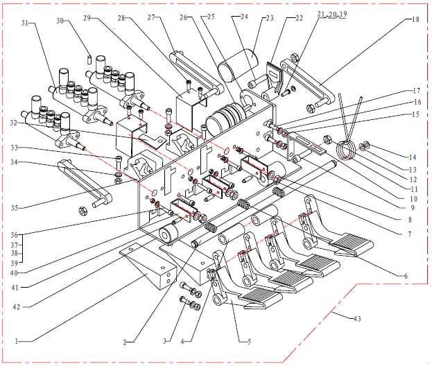
Parking brake Mechanical brake acting on rear wheels
 11 Brake System 11.1 General SPECIFICATIONS EJTC0010 Master cylinder Type Tandem type I.D. mm(in.) 20.64 mm (0.813 in.) Fluid level warning sensor Provided Brake booster Type Vacuum Boosting ratio 4.0
Hydraulic Bead Breaker Kit
 Hydraulic Bead Breaker Kit Owner s Manual WARNING: Read carefully and understand all ASSEMBLY AND OPERATION INSTRUCTIONS before operating. Failure to follow the safety rules and other basic safety precautions
AIR PAINT SHAKER OWNER'S MANUAL
 AIR PAINT SHAKER OWNER'S MANUAL WARNING: Read carefully and understand all INSTRUCTIONS before operating. Failure to follow the safety rules and other basic safety precautions may result in serious personal
2006 MINI Cooper SUSPENSION Wheels & Tires - Repair Instructions - Cooper (1.6L) R50/W10 & Cooper S
 R50/W10 & Cooper S") WHEELS 2002-05 SUSPENSION Wheels & Tires - Repair Instructions - Cooper (1.6L) R50/W10 & Cooper S 36 10 300 REMOVING OR INSTALLING FRONT OR REAR WHEEL NOTE: For Special Tool identification, see WHEEL AND
WHEELS 2002-05 SUSPENSION Wheels & Tires - Repair Instructions - Cooper (1.6L) R50/W10 & Cooper S 36 10 300 REMOVING OR INSTALLING FRONT OR REAR WHEEL NOTE: For Special Tool identification, see WHEEL AND
Large Hydraulic Bead Breaker
 Large Hydraulic Bead Breaker Owner s Manual WARNING: Read carefully and understand all ASSEMBLY AND OPERATION INSTRUCTIONS before operating. Failure to follow the safety rules and other basic safety precautions
HYDRAULIC PALLET TRUCK. MODEL No: PTE550 PART Nos OPERATION & MAINTENANCE INSTRUCTIONS
 HYDRAULIC PALLET TRUCK MODEL No: PTE550 PART Nos 7630171 OPERATION & MAINTENANCE INSTRUCTIONS 0604 Please read these instructions carefully before operating the truck Thank you for purchasing this CLARKE
SERIES OPERATION AND MAINTENANCE MANUAL
 SERIES OPERATION AND MAINTENANCE MANUAL This manual CONTAINS IMPORTANT WARNINGS, S and OTHER INSTRUCTIONS. Read and understand the instruction manual Carefully, before use and retain it for reference.
OPERATION AND MAINTENANCE MANUAL
 WREN IBT SERIES HYDRAULIC TORQUE WRENCHES IBT SQUARE DRIVE SERIES OPERATION AND MAINTENANCE MANUAL FOR WREN Products: POINT 75, 1IBT, 3IBT, 5IBT, 8IBT, 10IBT, 20IBT, 25IBT, 35IBT, 50IBT SQUARE DRIVE HYDRAULIC
TYRE CHANGER INSTRUCTION MANUAL
 V1.0 V201701 TYRE CHANGER INSTRUCTION MANUAL INDEX PAGE 1. Introduction:... 2 2. Safety Warnings:... 2 3. Technical data... 3 4. Transport:... 3 5. Unpacking & Inspection:... 3 6. Workplace requirements:...
Package Contents Part A (3) I-Beam (1) Base (2) Other parts
 I-Beam (1) Base (2) Other parts") Page 1 Installation Instructions for 81245 Adjustable Height Gantry Crane 1-Ton Capacity Table of Contents Important Safety Information pg. 2 Specific Operation Warnings pg. 2 Main Parts of Product pg.
Page 1 Installation Instructions for 81245 Adjustable Height Gantry Crane 1-Ton Capacity Table of Contents Important Safety Information pg. 2 Specific Operation Warnings pg. 2 Main Parts of Product pg.
MODEL 5500 Tire Repair Station
 MODEL 5500 Tire Repair Station Installation, Operation and Repair Parts Information Branick Industries, Inc. 4245 Main Ave P.O. Box 1937 Fargo, North Dakota 58103 P/N: 81-0047C TABLE OF CONTENTS SAFETY
operating instruction
 operating instruction a.560pn #125101 DE, EN, FR, SE Table of Contents Installation... 3 Tool use...4-5 Safety precautions...6-7 Troubleshooting and maintenance... 8 Technical specification... 9 Spare
2-1/4 Gallon Sprayer
 2-/4 Gallon Sprayer 94008 ASSEMBLY AND OPERATING INSTRUCTIONS 349 Mission Oaks Blvd., Camarillo, CA 930 Visit our Web site at http://www.harborfreight.com Copyright 2005 by Harbor Freight Tools. All rights
INSTRUCTION MANUAL ANGLE GRINDER PT W
 INSTRUCTION MANUAL ANGLE GRINDER PT50360 4½ INCHES 120V 60Hz 600W 5A 12,000 rpm C US Note : Before operating this tool, read this manual and follow all safety rules and operating instructions. This electric
Instruction Sheet CAUTION
 Instruction Sheet 11075 Tire Bead Breaker L2190 Rev. O 01/08 IMPORTANT RECEIVING INFORMATION Visually inspect all parts for shipping damage. If you find shipping damage, notify the carrier at once. Shipping
MODEL L/R/EF Sectional Tire Spreader
 MODEL L/R/EF Sectional Tire Spreader Installation, Operation & Repair Parts Information Branick Industries, Inc. 4245 Main Avenue P.O. Box 1937 Fargo, North Dakota 58103 REV08032016 P/N: 81-0195E TABLE
Cut Away Tire Bead Breaker Model 10101
 Cut Away Tire Bead Breaker Model 10101 DESCRIPTION PART NUMBER Hex Hd Cap Screw 7/16-14 x 2 12901 Handle Strap Pivot 36949 Piston 350455 Wiper 16720 U-Cup 16721 Spring Anchor 201360 Spring EXT OD.830ID.533R48L1.9300T
IMT Bead Breaker 1000
 Manual Part Number 99903638 IMT Bead Breaker 000 Revised 2050423 Copyright 204 Iowa Mold Tooling Co., Inc. All rights reserved IOWA MOLD TOOLING CO., INC. PO Box 89 Garner, IA 50438 Tel: 64-923-37 FAX:
HYDRAULIC PALLET TRUCKS
 HYDRAULIC PALLET TRUCKS HYDRAULIC PALLET TRUCKS MODEL Nos: PT550 GAL & PT685 GAL PART Nos: 7630234 & 7630236 OPERATION & MAINTENANCE INSTRUCTIONS 0204 Please read these instructions carefully before operating
BRAKE SYSTEM Return To Main Table of Contents
 BRAKE SYSTEM Return To Main Table of Contents GENERAL... 2 BRAKE PEDAL... 10 MASTER CYLINDER... 13 BRAKE BOOSTER... 16 BRAKE LINE... 18 PROPORTIONING VALVE... 19 FRONT DISC BRAKE... 20 REAR DRUM BRAKE...
50 TONNE HYDRAULIC PRESS MODEL NO: CSA50FP
 50 TONNE HYDRAULIC PRESS MODEL NO: CSA50FP PART NO: 7615202 OPERATION & MAINTENANCE INSTRUCTIONS WARNING: Read these instructions before using the press GC0516 INTRODUCTION Thank you for purchasing this
Index. 1. Important safety instructions Overview of the lift Installation instructions Operation instructions 8-9
 2 Index 1. Important safety instructions 4-5 1.1 Safety Warnings 1.2 Qualified personnel 1.3 Safety 1.4 Warning signs 2. Overview of the lift 6 2.1 General descriptions 2.2 Technical data 2.3 Construction
PRODUCT MANUAL TILE CUTTING MACHINE. . Operation. Parts List and Diagram SPECIFICATIONS CAUTION:
 FLORCRAFTT TM PRODUCT MANUAL SKU NUMBER 709-4242 SERIAL NUMBER: CAUTION: FOR YOUR OWN SAFETY READ INSTRUCTION MANUAL COMPLETELY AND CAREFULLY BEFORE OPERATING THIS 7 TILECUTTING MACHINE SPECIFICATIONS
AIR/HYDRAULIC LIFT TABLE CART 770-LB.
 AIR/HYDRAULIC LIFT TABLE CART 770-LB. OWNER S MANUAL WARNING: Read carefully and understand all MACHINE ADJUSTMENT AND OPERATION INSTRUCTIONS before operating. Failure to follow the safety rules and other
Maintenance Information
 51984144 Edition 6 May 2014 Air Paving Breaker MX60 & MX90 Maintenance Information Save These Instructions Product Safety Information WARNING Failure to observe the following warnings, and to avoid these
Service manual. English. F5 Corpus
 Service manual English F5 Corpus Introduction The Service Manual is intended for technical personnel who maintain and repair power wheelchairs. It is important that anyone who performs maintenance and
INSTRUCTION MANUAL Model OTR Tire Bead Breaker
 INSTRUCTION MANUAL Model 11040 OTR Tire Bead Breaker 2347 Circuit Way, Brooksville, Florida, USA 34604 Phone: (+1) 352-799-1111 Toll Phone: (+1) 877-775-4AME (4263) Fax: (+1) 352-799-1112 E-mail: sales@ameintl.net
DYNAPAC CONCRETE EQUIPMENT RAMIRENT. BG70 Power Floats INSTRUCTIONS & SPARE PARTS CATALOGUE BG70 - IS ENG
 DYNAPAC CONCRETE EQUIPMENT INSTRUCTIONS & SPARE PARTS CATALOGUE BG70 Power Floats BG70 - IS - 10682 - ENG SAFETY INSTRUCTIONS - MACHINES SUBMITTED : Powered with : Electric, Pneumatic, Petrol or Diesel
Indicates the operations which need proper care. Indicates a possibility of danger for the operators
 PRINTING CHARACTERS AND SYMBOLS Throughout this manual, the following symbols and printing characters are used to facilitate reading: Indicates the operations which need proper care Indicates prohibition
Marzocchi Suspension D-Street 24" D-Street 24" Technical instructions
 Technical instructions Exploded view - D-Street 24" 80 Rif. Code Quantity D-Street 24" 80 - Oil levels Position Oil type Quantity (cc) Right fork leg SAE 7,5-550013 185 Left fork leg SAE 7,5-550013 185
OPERATOR PROTECTIVE EQUIPMENT. Owner s Responsibility
 CONGRATULATIONS! You have just made the first step toward making your tire changing chores much easier! This DAA Assist Arm assembly guide will help you to assemble and install your new DAA Assist Arm
HEAVY DUTY TROLLEY JACK. Operation Manual
 HEAVY DUTY TROLLEY JACK 4T Operation Manual Make sure to read and fully understand the instruction manual before using this product and keep the manual properly 1 General Description Product Description
OPERATION AND PARTS MANUAL
 manual-r-pul, 30p, 21 April, 2000 MYUNGSAN HYDRAULIC ROTATABLE PULVERIZER OPERATION AND PARTS MANUAL MYUNGSAN Congratulations on your joining as a MYUNG SAN customer Myungsan pulverizer have been developed
IMPORTANT NOTE The warranty will be void if the pump has been altered in any way
 For technical questions and replacement parts, please call -800--788. Thank you very much for choosing a Northern Industrial Product! For future reference, please complete the owner's record below: Model:
OPERATING AND MAINTENANCE INSTRUCTIONS HYDRAULIC ELECTRICAL PUMPS HAM (Manual control) HAE (Electrical control)
 HAE (Electrical control)") OPERATING AND MAINTENANCE INSTRUCTIONS HYDRAULIC ELECTRICAL PUMPS HAM (Manual control) HAE (Electrical control) Part Nr : HA M 4 6 2 1 B C 1. Essential safety requirements. 2. Technical Characteristics.
OPERATING AND MAINTENANCE INSTRUCTIONS HYDRAULIC ELECTRICAL PUMPS HAM (Manual control) HAE (Electrical control) Part Nr : HA M 4 6 2 1 B C 1. Essential safety requirements. 2. Technical Characteristics.
Handout Activity: HA511
 Using a tire pressure gauge Engines: Motive Power Types: Handout Activity: HA511 HA511-2 Student/Intern information: Name Date Class Using a tire pressure gauge Summary There are two main types of tire
FPC815 Pneumatic Rivet Tool
 WARRANTY If you have any problems with this tool, please call FPC Corporation toll-free at 1-800-860-3838 before returning it to the place of purchase. FPC815 Pneumatic Rivet Tool FPC Corporation warrants
EP1306N 5 Gallon Can Extruder System Rev. A June EP1306N Operation Manual
 EP1306N Operation Manual 1 THIS PAGE HAS BEEN INTENTIONALLY LEFT BLANK 2 TABLE OF CONTENTS SECTION 1: SAFETY... 4 1. GENERAL SAFETY... 5 2. PUMP SAFETY... 5 3. FLUID PRESSURE AND COMPATIBILITY... 6 4.
Instruction Manual For Auto Shift Hydraulic Lift Table
 Instruction Manual For Auto Shift Hydraulic Lift Table Model Number: CART-550-AS Note: Owner/Operator must read and understand this Instruction Manual before operating the lift & tilt table. Contents 1
Marzocchi Suspension MZ I MZ I. Technical instructions
 Technical instructions Exploded view - MZ I - 100 Rif. Code Quantity Spare part list - MZ I - 100 Rif. Code Description Q.ty in the model Technical characteristics: Technical characteristics Single-crown
Robo-Assist Accessory
 Robo-Assist Accessory Kit 85607617 For use with BaseLine by COATS Tire Changers This is a supplement to your operating manual and covers the installation and use of the Robo-Assist accessory. If you do
3 Ton Trolley Jack. Please read and fully understand the instructions in this manual before operation. Keep this manual safe for future reference.
 Please dispose of packaging for the product in a responsible manner. It is suitable for recycling. Help to protect the environment, take the packaging to the local amenity tip and place into the appropriate
GROUNDSMASTER. 52 Recycler. for 120 Traction Unit. Model No & UP. Operator s Manual
 FORM NO. 8-980 Rev A GROUNDSMASTER 5 Recycler for 0 Traction Unit Model No. 077 79000 & UP Operator s Manual IMPORTANT: Read this manual carefully. It contains information about your safety and the safety
STRUT SPRING COMPRESSOR
 OWNER S MANUAL PRODUCT CODE: 1221T STRUT SPRING COMPRESSOR Capacity Stroke Spring Coil Spring Spring Coil Net Weight (Maximum) Thickness Length Diameter 1,000kg 330mm 10-18mm 210-570mm 100-158mm 36kg Made
Low Profile Wrenches Operation and Maintenance Manual
 Low Profile Wrenches Operation and Maintenance Manual http://www.torquetoolsinc.com Use the HEXPRO Series Low Profile Wrenches Model 2HP 4HP 8HP 14HP 30HP to install and remove large bolts that have minimal
* This operation manual was prepared in July Our company reserves the right to change or upgrade the
 H / E / S / H / B / O / N UNIVERSAL TRUCK TIRE CHANGER Operation Manual for Tire Changer (Truck) and Part List HT-300H * This operation manual was prepared in July 2012. Our company reserves the right
ProLine. 44 Mower. for 120 Traction Unit. Model No & Up. Operator s Manual
 FORM NO. 9 ProLine Mower for 0 Traction Unit Model No. 05 99000 & Up Operator s Manual IMPORTANT: Read this manual carefully. It contains information about your safety and the safety of others. Also become
WS INSTRUCTION MANUAL UNIVERSAL TRUCK TIRE CHANGER
 UNIVERSAL TRUCK TIRE CHANGER WS 02530 INSTRUCTION MANUAL Automotive Resources, Inc. 12775 Randolph Ridge Lane Manassas, VA 20109 (800) 562-3250 Web Site: http://www.ari-hetra.com E-Mail: webmaster@ari-hetra.com
CRD610 Automatic Fitting Inserter
 CRD610 Automatic Fitting Inserter OPERATIONS MANUAL VERSION 1.2 LAST EDITED 12.12.2018 cleanroomdevices.com 1 Table of Contents Title Page. 1 Table of Contents...2 1.0 General Product & Safety Information....3
Marzocchi Suspension MZ III MZ III. Technical instructions
 Technical instructions Exploded view - MZ III - 100 Rif. Code Quantity Spare part list - MZ III - 100 Rif. Code Description Q.ty in the model Technical characteristics: Technical characteristics Single-crown
6L Oil-less Air Compressor 53103
 6L Oil-less Air Compressor 53103 Operating Instructions Please read and save these instructions before attempting to assemble, install, operate or maintain the product. Protect yourself and others by observing
201B Series Belted Portable Drum Rollers Operator s Manual for Morse Belted Portable Drum Rollers
 Contents Page Receiving Procedures.................... 1 Warranty............................. 1 Safety Information..................... 1-2 Machine Description................... 3 Options.............................
Installation and Operating Instruction for Brake Caliper HW 150 HFA and HW 180 HFA E e
 Installation and Operating Instruction for Brake Caliper HW 150 HFA and HW 180 HFA E 09.736e Schaberweg 30-38 Phone +49 6172 275-0 61348 Bad Homburg Fax +49 6172 275-275 Germany www.ringspann.com info@ringspann.com
The following information shows the steps to change the rear brake pads and rotors on an E36 chassis.
 1 of 20 1/18/2010 9:15 PM See More DIY Articles Bookmark Site! The following information shows the steps to change the rear brake pads and rotors on an E36 chassis. Disclaimer: The following information
MODEL EGA200 OWNERS MANUAL
 3/8 RATCHET WRENCH MODEL EGA200 OWNERS MANUAL www.eaglecompressor.com 1-800-551-2406 READ THE ENTIRE MANUAL BEFORE PUTTING THIS TOOL IN SERVICE Limited Air Tool Warranty Wood Industries, Inc. warrants
PIN TYPE FORK POSITIONER WITH SHIFTING SF-F MODEL
 1 DESCRIPTION AND FUNCTIONING 1.1 Positioner 2 ASSEMBLY INSTRUCTIONS 2.1 Positioner 2.2 Hydraulic System 2.3 Mounting and dismounting forks 2.4 Protection Grid Assembling 2.5 Test operation 3 USE INSTRUCTIONS
IBT Series Square Drive Torque Wrenches
 IBT Series Square Drive Torque Wrenches Operation and Maintenance Manual Model.75, 1, 3, 5, 8, 10, 20, 25, 35, 50 http://www.torsionx.com Use the IBT Series Square Drive Torque Wrenches Model.75, 1, 3,
HexPro Series Low Profile Wrenches
 HexPro Series Low Profile Wrenches Operation and Maintenance Manual Model 2HP 4HP 8HP 14HP 30HP www.torquetoolsinc.com Use the HEXPRO Series Low Profile Wrenches Model 2HP 4HP 8HP 14HP 30HP to install
Hydraulic Motorcycle Lift. Model CML3 & CML3 AIR Part No: ASSEMBLY & OPERATING INSTRUCTIONS 0212
 Hydraulic Motorcycle Lift. Model CML3 & CML3 AIR Part No: 7610143 ASSEMBLY & OPERATING INSTRUCTIONS 0212 DO NOT ENTER UNDER THE PLATFORM UNLESS IT IS MECHANICALLY LOCKED (see instructions) DO NOT EXCEED
PRODUCT OPERATING MANUAL
 PRODUCT OPERATING MANUAL PANBLAST TM CS37 SUCTION BLAST CABINET Manual Number: ZVP PC 0069 00 SECTION 1. GENERAL INFORMATION 2. ASSEMBLY & INSTALLATION INSTRUCTIONS 3. OPERATING INSTRUCTIONS 4. MAINTENANCE
SECTION ZF FRONT AXLE
 04-101.01/ 1 2011JA14 SECTION 04-101.01 6 3 5 1 2 9 1. Upper radius rod 2. Lower radius rod 3. Caliper 4. BRAKE Disk 5. Pneumatic connector 6. Hub 7. steering knuckle 8. Grease Fitting 9. Pneumatic connector
HYDRAULIC PALLET TRUCK MODEL NO: PT540M/BM/CM & PT685BM/CM PART NO: , , , ,
 HYDRAULIC PALLET TRUCK MODEL NO: PT540M/BM/CM & PT685BM/CM PART NO: 7631700, 7631705, 7631710, 7631715, 7631720 OPERATION & MAINTENANCE INSTRUCTIONS LS0316 INTRODUCTION Thank you for purchasing this CLARKE
Maintenance Information
 80234313 Edition 2 May 2014 Air Grinder, Die Grinder, Sander and Belt Sander Series G1 (Angle) Maintenance Information Save These Instructions Product Safety Information WARNING Failure to observe the
AIR COMPRESSOR OPERATING INSTRUCTION AND PARTS LIST
 AIR COMPRESSOR OPERATING INSTRUCTION AND PARTS LIST BELT TYPE IMPORTANT PLEASE MAKE CERTAIN THAT THE PERSON WHO IS TO USE THIS EQUIPMENT CAREFULLY READS AND UNDERSTANDS THESE INSTRUCTIONS BEFORE STARTING
ProGuard Leverless Tire Changer For servicing single piece automotive and most light truck tire/wheel assemblies.
 ProGuard Leverless Tire Changer For servicing single piece automotive and most light truck tire/wheel assemblies. Safety Instructions Set-up Instructions Operation Instructions Maintenance Instructions
Spare parts list Trowel STG244 F TP
 Spare parts list Trowel STG244 F TP Valid from serial number Valid to serial number BGF111601- www.cp.com STG244 F TP Spare parts list General information This spare parts list applies to the following:
Operator s Manual. Nitro 1000 Nitro 1000X. Nitro 750 Nitro 750X. September REV0
 Operator s Manual Nitro 750 Nitro 750X Nitro 1000 Nitro 1000X September.27.2018REV0 Table of Contents Introduction...3 Safety.....4 Equipment Requirements......5 What You Have Received. 5 Serial Number...6
Operating Instructions 20 Ton Air/Hydraulic Service Jack
 MODEL: 3225 Operating Instructions 20 Ton Air/Hydraulic Service Jack WARNING: Important: Read these instructions and all warnings prior to using this equipment. Understand all operating procedures, safety
Model ET 5000W Operation and Service Manual
 Model ET 5000W Operation and Service Manual Patented 5/16 BALL Load Capacity: 5000 lbs The ET 5000W ESCALATE TRAILER offers ground level roll-on loading and roll-off unloading of equipment with non-tilting
Maintenance Information
 04581245 Edition 2 May 2014 Air Grinder, Die Grinder and Sander Series G2 (Angle) Maintenance Information Save These Instructions Product Safety Information WARNING Failure to observe the following warnings,
 Operation and Maintenance Manual http://www.torsionx.eu Use the MaxDrv Series Square Drive Torque Wrench Model.75, 1, 3, 5, 8, 10, 20, 25, 35, 50 to install and remove threaded fasteners requiring precise