TECHNICAL SERVICE BULLETIN: TSB
|
|
|
- Julie Mitchell
- 6 years ago
- Views:
Transcription
 PART NUMBERS B39124 / 700-7200 / 700-7200S Instruments Affected: ichemvelocity Automated Urine Chemistry Analyzers and iricell Systems Purpose: Provide Global Service Organization and")
1 TECHNICAL SERVICE BULLETIN: TSB To: From: Global Service Organization, ichem VELOCITY and iricell Distributors Iris Diagnostics Service and Support Date: 10 June 2015 Subject: STRIP PROVIDER MODULE (SPM) PART NUMBERS B39124 / / S Instruments Affected: ichemvelocity Automated Urine Chemistry Analyzers and iricell Systems Purpose: Provide Global Service Organization and distributor partners with information about how to resolve SPM related issues with lower cost repair parts instead of replacing the entire module. Discussion: The SPM is a high cost module in the ichemvelocity Analyzer. In order to reduce costs associated with servicing this analyzer, information pertaining to resolving SPM related problems with lower cost repair parts instead of replacing the entire module is provided in this Technical Bulletin. IMPORTANT NOTES: 1. Certain repair parts are backwards compatible to specific revision levels of the SPM. For these repair parts, the information will be documented below the section and replacement part number in this bulletin. 2. There will be situations when the entire Strip Provider Module will require replacement; however, this Technical Bulletin provides multiple examples of how the SPM can be repaired at a lower level instead of replacing the entire module. TSB Rev AA
2 1. Strip Load Cylinder, Spare (P/N S) Movement or rotation problems related to the Strip Load Cylinder are issues that can many times be resolved by the customer. Replacing the Strip Load Cylinder normally does not require an on-site service visit. This part can be shipped directly to the customer for replacement. 2. PCBA, SPM Strip Loading Cylinder Sensor (P/N ) This sensor on the back of the SPM for the Strip Load Cylinder can be replaced by unplugging the connector from the sensor, removing the screws/ fasteners holding the sensor in place, removing the old sensor, installing the new sensor and plugging in the connector. The symptoms of this sensor going bad will be the instrument will remain in constant measure mode and will not process samples. 3. SPM Magnet Assembly Retrofit Kit (P/N ) This kit is used if the magnet on the back of the Strip Loader Module needs to be replaced. The magnet is secured to the Strip Load Cylinder by one screw. If this magnet falls off the back of the strip loader module, the SPM strip loading cylinder sensor will not be able to determine when the Strip Loader Cylinder is in the correct locked position. This will result in the instrument remaining in constant measure mode and the instrument will not process samples. 4. SPM Home Sensor Replacement Kit P/N ( ) This kit contains one pre-assembled cable, connector and home sensor that will work for the wiper, extractor, feeder, or flipper. The SPM home sensor replacement procedure can be done with the SPM installed or with the SPM removed from the instrument. The instructions below document how to replace an SPM home sensor with the SPM removed from the instrument. Step a: Turn off all electrical power to the Instrument. Remove the SPM from the Instrument. Step b: Remove the Sensor: Remove the malfunctioning sensor and cable. Discard the screws and washers. Notice how the cable was routed and tied so the pattern can be repeated when installing the replacement cable and sensor. 2

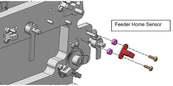
3 Step c: To Install the Wiper, Flipper or Extractor Sensor: Use the short Screws provided. Washers are not to be used. Route the cable along the same path as the cable just removed. To install the feeder home sensor, Use the white Spacers and the long Screws provided. Washers are not to be used. Route the cable along the same path as the cable just removed. 3


4 Step d: Secure the cable. Use cable ties provided in the kit to secure the new cable. Step e: Use markers provided to properly identify the new cable. Step f: Before re-installing the SPM, check that the Strip Provider Housing opens and closes freely without pulling on the Cables. Step g: Re-install the SPM, verify the SPM calibrations in accordance with the Service Manual, and conduct the Performance Verification. 4
5 5. SPM Strip Loading Housing Cover (P/N B39121) This top cover was modified and implemented in instrument serial number V Instruments that experience issues with strips jams when loading strips should be checked to determine if this top cover is installed on the SPM. The Strip Loading Housing Cover (P/N B39121) is backwards compatible from the current SPM P/N B39124 to SPM Revision AD. 6. SPM Cover Crossbar Kit (P/N ) This part is replaced if the SPM has problems associated with opening and closing the SPM cover. Instrument S/N VO1224 is the first instrument that was manufactured with the SPM Cover Crossbar Kit. All Strip Provider Modules P/N Revision AD and later and Strip Provider Modules P/N B39124 are manufactured with the SPM Cover-Crossbar Kit. This kit contains the following parts: Captive SPM cover screws 2 EA P/N Springs 2 EA P/N Retainer washers 3 EA P/N Crossbar 1 EA P/N Crossbar retaining screws 2 EA P/N Instructions 1 EA P/N Replacing the captive SPM cover screws, springs, washers, crossbar and crossbar retaining screws enable the SPM cover to securely closed and this make it easier for the operator to open and close the SPM. The SPM cover-crossbar kit can be used with SPMs P/N Revision V and later and all SPMs P/N B
 Verify the extractor presence sensor flat cable is plugged in at both ends.")

6 7. Extractor presence sensor (P/N ) Extractor presence sensor flat cable (P/N ) Extractor magnet assembly, spare (P/N S) If the SPM wiper is singulating the strip to the extractor but the extractor is ejecting the strip back into the SPM strip housing chamber, the following must be checked: a) Verify the extractor presence sensor flat cable is plugged in at both ends. b) SPM extractor and wiper calibration should be verified. c) If line items 7a and 7b have been verified as correct, verify operation of the extractor presence sensor in chemistry service mode. Make sure the SPM strip at extractor consistently changes state between 1 and 0 when a chemistry strip is inserted and removed from the extractor. d) Problems associated with the chemistry strip being ejected back into the SPM strip housing chamber are normally resolved by replacing the extractor presence sensor, extractor presence sensor flat cable, and extractor magnet assembly. 6
.")
7 8. For issues related to the ichemvelocity chemistry strip being placed upside down on the Strip Conveyor System, the following items must be checked: a) Make sure the chemistry strips properly loaded into the SPM. If the chemistry strips are loaded with the black marker facing the front of the SPM, the chemistry strips will be placed upside down on the Strip Conveyor System (SCS). This will result in a Chem N/A and Strip Deviate result. b) If the chemistry strips are properly loaded into the SPM but the strips are still being placed upside down onto the SCS, check to ensure the SPM feeder and flipper connectors are properly plugged into the SPM interconnect board (See diagram below - J20 and J21). If the connectors are plugged in properly, verify the SPM feeder and flipper calibration. If the SPM feeder is not stopping at the correct location when the SPM strip presence and orientation sensor is determining the orientation of the chemistry strip, the flipper will fail to rotate the chemistry strip to have the pads facing the upward position. If the feeder calibration is correct, check for proper operation of the SPM flipper. 7

 Most issues related to the chemistry strips being placed upside down onto the Strip Conveyor System are related to the chemistry strips being loaded backwards into the SPM or the SPM feeder")
8 c) If line items 8a and 8b are correct, verify proper operation of the SPM presence and orientation sensor in chemistry service mode. Make sure the SPM strip presence or orientation sensor changes state between 1 and 0 when a strip is placed in front of and removed away from the sensor. If the sensor is not working correctly, replace the sensor (P/N ). d) Most issues related to the chemistry strips being placed upside down onto the Strip Conveyor System are related to the chemistry strips being loaded backwards into the SPM or the SPM feeder calibration being incorrect. 9. For strip jams at the extractor gate, check the following: a) Determine if there is any debris in the SPM chamber. Make sure to check the inner and outer grooves of the SPM chamber. b) Determine if there is any debris inside the extractor. The extractor crossbar will need to be removed to check for debris inside the extractor. c) Verify the SPM wiper and extractor calibration. d) Verify the extractor gate has both retaining screws holding the gate in place. e) Remove the extractor gate to inspect any debris inside the gate. f) Inspect the extractor gate to ensure the static gate seal is in good condition. g) If there are any issues with the extractor gate, replace using the SPM extractor gate kit (P/N ). Diagram shown below. 8

9 SPM EXTRACTOR GATE KIT (P/N ) Screw, Shoulder: P/N EA Spring, Compression: P/N EA Extractor Gate, Static P/N EA Extractor Gate, Dynamic P/N EA After installing the SPM extractor gate kit, conduct SPM performance verification in accordance with the ichemvelocity PV Verification Data Sheet
10 10. SPM COUPLING REPLACEMENT KIT (P/N ) Important Notes: 1. This procedure is documented in TSB The SPM coupling replacement kit (P/N ) can be used with SPM revisions P/N Revision AA and later and all SPMs P/N B There are specific tool requirements for this procedure. The torque screwdriver and hex tools required for this procedure are not included in the SPM Coupling Replacement Kit. 4. The SPM coupling replacement kit contains the coupling assemblies for the SPM wiper and extractor. The SPM feeder and flipper coupling assemblies are made of a different material and have a very low failure rate. Couplings for these assemblies are ordered separately from this kit. The SPM Coupling Replacement Kit is made up of the following parts: P/N Disk, Coupling (2 EA) P/N Coupling with screw (2 EA) P/N Coupling with screw (2 EA) P/N Tool, Shim (1 EA) P/N Instructions, Kit (1 EA) Before you Begin: You must have these tools available: Tools: Calibrated torque screwdriver with 2 mm hex bit 2 mm hex key 5/32 hex key Shim Tool P/N (Provided with the kit) Important Notes: 1. This procedure can be performed with the SPM inside the instrument or with the SPM removed from the instrument. 2. This Technical Service Bulletin shows this procedure being performed on the SPM wiper coupling assembly with the SPM remaining inside the instrument. 3. The procedure to change the SPM extractor coupling assembly is identical to the SPM wiper coupling assembly. 10


11 CAUTION: When performing the SPM coupling replacement, be careful not to remove the ribbon cable from the SPM extractor presence sensor PCB. Step a: Turn off the instrument. Gain access to the SPM coupling assemblies. Using a 2 mm hex key, loosen screws (2ea) of the wiper coupling assembly. SPM Wiper Coupling Assembly Screw SPM Extractor Coupling Assembly SPM Wiper Motor SPM Extractor Motor Step b. Using a 5/32 hex key, remove and set aside for later use screws (4 per motor) that mount the wiper motor. Carefully remove the motor. SPM Wiper Motor 11


12 Step c: Install the couplings onto the wiper shaft as shown in the picture below. Clean the wiper shaft and shaft bores. Orient the flags horizontal as shown and slide the Coupling onto the shafts. Note that the heads of the coupling screws are oriented to the top, the same as the screws on the home sensor flags Nylon Coupling Disk with hole Wiper Coupling Assembly with 2 mm Screw Step d: Slide the couplings onto the wiper shaft until they contact the flags. Maintain the couplings orientation as shown (screw head at top). Tighten the coupling screws so that they grip onto the shaft. Torque the coupling screw to 11 in-lb. (The 11 in-lb. is a requirement on both the wiper coupling and extractor coupling assemblies). Press Disk in place The wiper home flag is horizontal and the screw head for the coupling assembly is facing upward. Extractor Motor Wiper Motor Rotate Wiper Motor Shaft with the D-flat of the shaft in a vertical position. D-flat of the motor shaft. 12

 Torque the coupling screw to 11 in-lb 725-7252 Shim Tool Gently press on Plastic Rotating Disk inside the SPM Torque the coupling screw on the wiper coupling to 11 in-lb.")
13 Step e: Align and secure the wiper coupling. Using the shim tool, press the coupling stack to set a.010 inch gap Shim Tool,.010 in place. D-Flat on motor shaft is vertical Wiper motor Step f: Orient the D-flat shaft of the wiper motor vertically as shown. The coupling hub on the motor must not move from orientation shown. The flat must remain vertical. 1) Squeeze the Coupling stack to set.010 gap 2) Torque the coupling screw to 11 in-lb Shim Tool Gently press on Plastic Rotating Disk inside the SPM Torque the coupling screw on the wiper coupling to 11 in-lb. Rotate the wiper so that the flag is in horizontal orientation as shown. Install the shim tool onto the wiper coupling stack as shown. 13
.")
14 Step g. Torque the coupling screw on the coupling to 11 in-lb. Remove the shim tool. Step h: Verify SPM calibrations. Pay particular attention to the SPM calibration for the coupling assembly that was just replaced (Wiper or Extractor). Perform SPM calibrations as necessary using the SPM calibration procedure documented in the ichemvelocity service manual. Step i: Conduct SPM performance verification in accordance with the ichemvelocity Performance Verification Data Sheet SPM feeder and flipper coupling assemblies (P/N ): The Mean Time Between Failure for the feeder and flipper coupling assemblies is very low; however, if either of these coupling assemblies fail, remove the coupling with a 2mm hex key and replace. 14

15 12. SPM Motors: In the event an SPM motor fails, loosen the associated motor coupling assembly. Use a 5/32 hex key to remove the SPM motor retaining screws. Install the new motor, reinstall the motor coupling assembly, tighten the SPM motor retaining screws, and Conduct SPM performance verification in accordance with the ichemvelocity PV Verification Data Sheet This part is replaced upon failure. 13. To address strip jams between the SPM and SCS, conduct the following: a) Verify the SPM-SCS alignment in accordance with TSB b) Verify the SCS links are in good condition. c) Verify the SPM ramp assembly is clean. d) Verify the routine maintenance is being conducted on the SCS and that the SCS is clean. 15

 - SPM Ramp Alignment Tool (P/N: 725-7206) - TSB2014-016 (Technical Service Bulletin explaining the SPM-SCS alignment) Step a: Turn off the instrument.")
16 13. SPM TILT RELASE BLOCK KIT P/N While the SPM tilt release block is connected to the foundation plate and not the actual Strip Provider Module, complaints related to the tilt release block will be associated with the Strip Provider Module. See instructions below on how to replace this part. Before you Begin: You must have these tools and parts available: - SPM Tilt Release Block Kit (P/N ) - 1/8 Allen Wrench - 7/64 Allen Wrench - #1 Phillips Screwdriver - SPM-SCS Alignment Tool (P/N ) - SPM Ramp Alignment Tool (P/N: ) - TSB (Technical Service Bulletin explaining the SPM-SCS alignment) Step a: Turn off the instrument. Step b: Using a 7/64 Allen Wrench, loosen and remove the SPM tilt release block retaining screw. Set the screw and washers to the side; they will be used to reinstall the new SPM tilt release block kit. 16

17 Step c: Using a 1/8 Allen Wrench, loosen and remove the SPM Z block retaining screws. Set the screws and washers to the side; they will be used to reinstall the new SPM tilt release block kit. Note: When loosening the SPM tilt wheel, it is recommended to count the number of turns it takes to remove the SPM tilt release block from the SPM tilt wheel. This will provide the service engineer with an approximate calculation of the SPM tilt adjustment when installing the SPM tilt release block kit. Step d: Rotate the SPM tilt wheel counter-clockwise until the threads for the SPM tilt wheel are out of the SPM tilt release block. Step 2: Step 4: Step 3: Step e: Remove the SPM tilt release block kit from the box. The screws and washers in this kit are spares in the event the original screws were misplaced. Step f: Install the new SPM tilt release block kit. Step g: Using TSB , perform the SPM-SCS alignment. Step h: Make sure all SPM retaining screws are tightened after performing the SPM-SCS alignment. Step i: Conduct SPM performance check and ichemvelocity performance verification to make sure the SPM is aligned and working properly. Step j: After successful performance check and performance verification, return the instrument to normal operating condition. End Procedure. 17
HOW TO REPLACE THE ICHEMVELOCITY WASTE FILTER AND PERFORM THE WASTE LINE FLUSH FOR BECKMAN UA CALL CENTER USE
 HOW TO REPLACE THE ICHEMVELOCITY WASTE FILTER AND PERFORM THE WASTE LINE FLUSH FOR BECKMAN UA CALL CENTER USE 300-5587 Rev AA SAFETY PRECAUTIONS AND IRIS DIAGNOSTICS CONTACT INFORMATION SAFETY PRECAUTIONS:
RMK HANDLEBAR KIT P/N ; ; APPLICATION BEFORE YOU BEGIN KIT CONTENTS. Verify accessory fitment at Polaris.com.
 RMK HANDLEBAR KIT P/N 2883835; 2883836; 2883837 APPLICATION Verify accessory fitment at Polaris.com. BEFORE YOU BEGIN Read these instructions and check to be sure all parts and tools are accounted for.
Sachs 48mm Closed Cartridge fork Service Manual
 Sachs 48mm Closed Cartridge fork Service Manual 1 Fork seal driver 2 Special soft jaws 3 Fork cap wrench 4 Rebound rod holding tool 5 Compression assembly holding tool 6 Retaining clip tool Special Tools
FlexJet Carriage Circuit Board (PCB) Replacement
 Replacement") P/N: 111484 R0 14140 NE 200th St. Woodinville, WA. 98072 PH: (425) 398-8282 FX: (425) 398-8383 ioline.com FlexJet Carriage Circuit Board (PCB) Replacement Notices: Warning! Ensure that all AC power cables
P/N: 111484 R0 14140 NE 200th St. Woodinville, WA. 98072 PH: (425) 398-8282 FX: (425) 398-8383 ioline.com FlexJet Carriage Circuit Board (PCB) Replacement Notices: Warning! Ensure that all AC power cables
RTX 2000 Thomas Compressor TG-550 Graco PN
 RTX 2000 Thomas Compressor TG-550 Graco PN 246888 Print of Complete Compressor--------------Page 2 Instruction for Kit 118628-------------------Page 3 Instruction for Kit 287845-------------------Page
Installation Manual for VHM-25 Series Arms Channel Mount
 3875 Cypress Drive Petaluma, CA 94954 800.228.2555 707.773.1100 Fax 707.773.1180 www.gcx.com Installation Manual for VHM25 Series Arms Channel Mount Install Time: 1015 minutes The purpose of this manual
This is the Unpacking Guide for the Optibike Pioneer Allroad electric bicycle. The Guide provides information required to remove the Allroad from the
 This is the Unpacking Guide for the Optibike Pioneer Allroad electric bicycle. The Guide provides information required to remove the Allroad from the box and assemble it. If you have not assembled a bicycle
Rekluse Motor Sports. The z-start Clutch LTR 450. Installation Guide Copyright 2002 Rekluse Motor Sports z-start Revision 3.
 Rekluse Motor Sports The z-start Clutch LTR 450 Installation Guide Copyright 2002 Rekluse Motor Sports z-start Revision 3.000 RMS166 LTR 450 191-266 Manual Revision: 032306 Rekluse Motor Sports, inc. 110
3M Overhaul Service Kit
 SERVICE INSTRUCTIONS FOR 3M 12,000 RPM 3 in. (77 mm) RANDOM ORBITAL SANDERS 3M Overhaul Service Kit The part number 20346, 3M Overhaul Service Kit, contains all the replacement parts that naturally wear
Replacing the pick rollers P.N X
 Instruction Sheet Replacing the pick rollers P.N. 118-9717-0X For assistance while replacing the pick rollers, contact you local Tektronix representative. In the U.S. and Canada, call 1-800-835-6100. 1.
200 Shadylane Drive Philipsburg, PA Phone: (814) Fax: (814) Service Manual. Model 642E Centrifuge
 Fax: (814) Service Manual. Model 642E Centrifuge") 200 Shadylane Drive Philipsburg, PA 16866 Phone: (814) 342-6205 Fax: (814) 342-4510 www.druckerdiagnostics.com Service Manual Model 642E Centrifuge MODEL 642E SERVICE MANUAL REV: Original Issue 1 CONTENTS
200 Shadylane Drive Philipsburg, PA 16866 Phone: (814) 342-6205 Fax: (814) 342-4510 www.druckerdiagnostics.com Service Manual Model 642E Centrifuge MODEL 642E SERVICE MANUAL REV: Original Issue 1 CONTENTS
INSTALLATION GUIDE CRF150R Manual Revision:
 REKLUSE MOTOR SPORTS The z-start Pro Clutch INSTALLATION GUIDE CRF150R 191-810 Manual Revision: 032508 2002 Rekluse Motor Sports Rekluse Motor Sports, Inc. 110 E. 43rd Street Boise, Idaho 83714 208-426-0659
INSTALLATION GUIDE. KTM 125, 144, Stroke KTM 250, Stroke KTM 250 SXF, XC, XC-W KTM 450, 505 SXF Manual Revision:
 REKLUSE MOTOR SPORTS The z-start Pro Clutch INSTALLATION GUIDE KTM 125, 144, 200 2-Stroke KTM 250, 300 2-Stroke KTM 250 SXF, XC, XC-W KTM 450, 505 SXF 191-836 Manual Revision: 050307 2002 Rekluse Motor
Auto-Lift Operating System
 Installation Instructions Parasol Cellular Shades Auto-Lift Operating System CONTENTS Getting Started: Product View... 1 Tools and Fasteners Needed... 2 Installation: Installation Overview... 3 STEP 1
2010+ Audi B8 S4/S5 3.0T S-FLO Intake Kit INSTALLATION GUIDE FOR RACING USE ONLY
 INSTALLATION GUIDE 2010+ Audi B8 S4/S5 3.0T S-FLO Intake Kit FOR RACING USE ONLY Congratulations on your purchase of the AWE Tuning S-FLO Intake for the 2010+ Audi B8 S4 and B8 S5 3.0T. Exquisite build
FOR SIT-STAND WORKSTATION
 INSTALLATION MANUAL FOR SIT-STAND WORKSTATION Weight Capacity: 6.5-24.5 lbs. 6017180 Rev. B Contents Tools Required / Supplied Part Kits / Warnings/Disclaimers...2 Base Installation Clamp Mount Base Location...3
Installation Guide Philips MP90 VHM Wall Mount Kit
 Installation Guide Philips MP90 VHM Wall Mount Kit The purpose of this guide is to describe the procedures for installing the MP90 VHM Wall Mount Kit. Table of Contents Section 1.0: Mounting the VHM-Series
Installation Manual TWM Performance Short Shifter Cobalt SS/SC, SS/TC, HHR SS, Ion Redline and Saab 9-3
 Page 1 Installation Manual TWM Performance Short Shifter Cobalt SS/SC, SS/TC, HHR SS, Ion Redline and Saab 9-3 Please Note: It is preferable to park on a flat surface, as you will have to engage and disengage
Installation Instructions 1812 Folder Disk Clutch Retrofit Kit Martin Yale #WRA
 Installation Instructions 1812 Folder Disk Clutch Retrofit Kit Martin Yale #WRA1812510 Background: Early production Martin Yale Model 1812 Folders were originally equipped with a spring-clutch type feed
Lingenfelter Camaro SS Shift Knob Boot Adapter Kit Installation Instructions
 Lingenfelter 2010-2013 Camaro SS Shift Knob Boot Adapter Kit Installation Instructions PN: L350191410 Revision - 1.1 Lingenfelter Performance Engineering 1557 Winchester Road Decatur, IN 46733 (260) 724-2552
DUETTE POWERRISE SHADES
 DUETTE POWERRISE SHADES A B OPEN CLOSE INSTALLATION OPERATION CARE PRODUCT VIEW Spacer Blocks Installation Brackets End Cap Sensor Eye and Manual Button Fabric-Covered Valance PowerRise with Platinum Technology
Throttling Pendulum Gate O-ring Replacement Procedure Rev. A, May 2012
 Throttling Pendulum Gate O-ring Replacement Procedure Rev. A, May 2012 This procedure covers the replacement of the gate O-ring of the Nor-Cal Pendulum Gate Valve, with the gate valve housing installed
Caution Improper installation could result in tape failure, mounting hardware, and reader. Please read instructions before installing!
 Elgo Sensor Mounting Motion High Speed Landing/Positioning System The encoded tape used for the landing system is suspended between two mounting brackets that attach to the car rail using forged clips
200 Shadylane Drive Philipsburg, PA Phone: (814) Fax: (814) Service Manual
 Fax: (814) Service Manual") 200 Shadylane Drive Philipsburg, PA 16866 Phone: (814) 342-6205 Fax: (814) 342-4510 www.druckerdiagnostics.com Service Manual Model 755VES Centrifuge MODEL 755VES SERVICE MANUAL REV: A 1 CONTENTS 1 PREFACE...
200 Shadylane Drive Philipsburg, PA 16866 Phone: (814) 342-6205 Fax: (814) 342-4510 www.druckerdiagnostics.com Service Manual Model 755VES Centrifuge MODEL 755VES SERVICE MANUAL REV: A 1 CONTENTS 1 PREFACE...
Electric Actuator Installation, Operation & Maintenance Manual
 Electric Actuator Installation, Operation & Maintenance Manual For Use with: All Standard AC Voltage Models Additional supplements may be needed for selected optional equipment including, but not limited
160S Rewind Option Kit Installation Instructions
 Installation Instructions GENERAL This kit includes the parts and documentation necessary to install the Media Rewind Option into the Zebra 160S printer. Read these instructions thoroughly before attempting
BETTIS SERVICE INSTRUCTIONS DISASSEMBLY AND REASSEMBLY FOR CB-SR-S SEISMIC SPRING RETURN SERIES PNEUMATIC ACTUATORS
 BETTIS SERVICE INSTRUCTIONS DISASSEMBLY AND REASSEMBLY FOR CB-SR-S SEISMIC SPRING RETURN SERIES PNEUMATIC ACTUATORS PART NUMBER: 102264 REVISION: "C" DATE: November 2000 Page 1 of 11 1.0 INTRODUCTION 1.1
Auto Sentry-eXP Maintenance. Revised 12/21/07
 Auto Sentry-eXP Maintenance Revised 12/21/07 Maintenance Procedures for Auto Sentry exp Bill Dispenser Credit Card Reader Bill Acceptor Bill Dispenser Maintenance Bill Dispenser Problem / Cause Bill Dispenser
Rekluse Motor Sports. The z-start Clutch CRF 250X. Installation Guide Copyright 2002 Rekluse Motor Sports z-start Revision RMS116 CRF 250X
 Rekluse Motor Sports The z-start Clutch CRF 250X Installation Guide Copyright 2002 Rekluse Motor Sports z-start Revision 3.000 RMS116 CRF 250X 191-216 Manual Revision: 103105 Rekluse Motor Sports, inc.
Operation and Maintenance Manual
 BM / BMA Hydrometers ½ Operation and Maintenance Manual i This manual is intended for use by the users of this equipment. The information contained herein is the property of the Arad Ltd. Dalia and may
4. Remove the bed bolts A.) Using a 1/2 socket, remove the four inner bed bolts. B.) Using a T-25 Torx driver, remove the four outer bed bolts.
 Using a 1/2 socket, remove the four inner bed bolts. B.) Using a T-25 Torx driver, remove the four outer bed bolts.") Installation Instructions Part Number 883-282 Intake kit with scoop 2008-14 Polaris Ranger RZR 800 Tools Required For Installation: 7/16 and 1/2 Wrenches. 10mm, 7/16, and 1/2 Sockets. T-25 Torx driver.
Installation Instructions Part Number 883-282 Intake kit with scoop 2008-14 Polaris Ranger RZR 800 Tools Required For Installation: 7/16 and 1/2 Wrenches. 10mm, 7/16, and 1/2 Sockets. T-25 Torx driver.
Stealth Pro Ratchet Shifter
 Installation Instructions Stealth Pro Ratchet Shifter Part Number 81120 & 81121 (see www.bmracing.com for the latest technical product information) 2010, 2006 by B&M Racing and Performance Products The
Installation Instructions
 L-PB L-PW Installation Instructions Component Checklist Arm Assembly (with pre-assembled Desk Clamp) Hardware Desk Single Rotation Limiter (x1) (x1) 2mm Allen (x1) Cable Clip (x4) Spacer Bush (x4) Fasteners
VHM-P (Non-Locking) and VHM-PL (Locking) Variable Height Arm with Slide-In Mounting Plate
 and VHM-PL (Locking) Variable Height Arm with Slide-In Mounting Plate") 3875 Cypress Drive Petaluma, CA 94954 800.228.2555 +1.707.773.1100 Fax 707.773.1180 www.gcx.com VHM-P (Non-Locking) and VHM-PL (Locking) Variable Height Arm with Slide-In Mounting Plate (Refer to qualified
3875 Cypress Drive Petaluma, CA 94954 800.228.2555 +1.707.773.1100 Fax 707.773.1180 www.gcx.com VHM-P (Non-Locking) and VHM-PL (Locking) Variable Height Arm with Slide-In Mounting Plate (Refer to qualified
PRO RATCHET UNIVERSAL SHIFTER
 Installation Instructions PRO RATCHET UNIVERSAL SHIFTER Fits: GM, Ford and Chryslers w/automatic Transmission See Application Guide for Specific Vehicles Catalog # 80842 WORK SAFELY! For maximum safety,
9-I DUETTE SHADES POWERVIEW MOTORISATION
 SECTION: 9-I DUETTE SHADES POWERVIEW MOTORISATION 9-I DUETTE SHADES POWERVIEW MOTORISATION Product View Installation Brackets End Cap Manual Control Button Fabric-Covered Headrail Bottom Rail Battery Wand
INSTALLATION INSTRUCTIONS RATTLER STEEL RUNNING BOARDS FORD TRANSIT VAN (FULL SIZE)
") INSTALLATION INSTRUCTIONS PARTS LIST: 1 32-inch Steel Running Board 1 8-1.25mm x 35mm Hex Bolt 1 96-inch Steel Running Board 13 8-1.25mm x 25mm Hex Bolt 5 Passenger Side/Driver Side Mounting Brackets 20
INSTALLATION INSTRUCTIONS PARTS LIST: 1 32-inch Steel Running Board 1 8-1.25mm x 35mm Hex Bolt 1 96-inch Steel Running Board 13 8-1.25mm x 25mm Hex Bolt 5 Passenger Side/Driver Side Mounting Brackets 20
Installation Manual for Philips Intellivue MP5/20/30 VHM-25 Channel Mount Kit
 3875 Cypress Drive Petaluma, CA 94954 800.228.2555 707.773.1100 Fax 707.773.1180 www.gcx.com Installation Manual for Philips Intellivue MP5/20/30 VHM-25 Channel Mount Kit Install Time: 10-15 minutes The
INSTALLATION GUIDE. Kawasaki KLR Manual Revision:
 REKLUSE MOTOR SPORTS The z-start Pro Clutch INSTALLATION GUIDE Kawasaki KLR650 191-640 Manual Revision: 030308 2007 Rekluse Motor Sports Rekluse Motor Sports, Inc. 110 E. 43rd Street Boise, Idaho 83714
TOYOTA TUNDRA TVIP V4 Preparation
 Preparation Part Number: PT398-00100 PT398-00100-AA Conflicts Do not install into vehicles without RKE system. Recommended Sequence of Application Item # Accessory 1 TVIP/RES Any TVIP or RES system 2 XM
8G Brake Assembly Alignment
 8G Brake Assembly Alignment 8G (9-5250) This document explains how to do the 8G (9-5250) brake assembly alignment in order to eliminate noise in the drive system coming from the mis-aligned brake plates.
Desktop 5.5 Z Axis Retrofit
 Page 1 Kit parts Desktop 5.5 Z Axis Retrofit Carriage plate with stop bolt and Z proximity switch installed Zip ties Spare bolts Spindle mounting plate with stop bolt, spring mount, and rail Z proximity
Assembly Instructions
 Drive Technology \ Drive Automation \ System Integration \ Services *2450452_0617* Assembly Instructions Didactics - Gear Unit Technology Helical Gear Unit R57F AD2 Edition 06/2017 2450452/EN SEW-EURODRIVE
SPE-DEX 3100 Solid Phase Extraction System
 SPE-DEX 3100 Solid Phase Extraction System Service Manual 16 Northwestern Drive, Salem, NH 03079 Telephone: (603) 893-3663 Toll-Free: (800) 997-2997 USA Only Website: www.horizontechinc.com Copyright 2016
Universal Pitch Adjustable Wall Mount For Flat Panel Display UPM-2401
 INSTALLATION INSTRUCTIONS Universal Pitch Adjustable Wall Mount For Flat Panel Display UPM-2401 Your new Chief Universal Pitch-Adjustable Wall Mount (UPM-2401) is a quick disconnect mounting system with
Operations Manual Eagle 1000 Series Stretch Wrapper
 Operations Manual Eagle 1000 Series Stretch Wrapper Models A & B - 1 - READ ALL INSTRUCTIONS CONTAINED IN THIS MANUAL PRIOR TO MACHINE INSTALLATION! - 2 - Contents page 1. Machine Safety Information 1.1
INSTALLATION MANUAL
 INSTALLATION MANUAL 1500350 Parts List 1 Driver / left inner fender liner 1 Passenger / right inner fender liner 4 Z-hanger brackets 1 Thread-set bolt, M6 1 Thread-set washer 1 Thread-set spacer 22 Hex
MAINTENANCE MANUAL LP SERIES RAIL SLIDES
 ENGINEERED PRODUCTS ISO 9001 REGISTERED MAINTENANCE MANUAL LP SERIES RAIL SLIDES PNEUMATIC CYLINDER SHROUD SIDE SHROUD SIDE SHROUD LP1 SOLID STATE CYLINDER SWITCH CARRIAGE PLATE LP2 LUBE ACCESS PORT SHOCK
INSTALLATION INSTRUCTIONS
 INSTALLATION INSTRUCTIONS X-08 TM /CEX-08 T M Type 1F HIGH SECURITY ELECTRONIC LOCK 1 Table of Contents INTRODUCTION... 3 BASIC TOOLS AND MATERIALS NEEDED... 3 LOCK PARTS FOR INSTALLATION... 4 INSTALLATION
Instruction Sheet. Kit Numbers: , , & CRANK PULLEY KIT DISASSEMBLY. Package Contents
 Instruction Sheet Kit Numbers: 5600, 5700, 5800 & 5300 CRANK PULLEY KIT WARNING: FAILURE TO FOLLOW INSTRUCTIONS could result in personal injury and/or damage to unit. Read, understand, and follow all safety
N/S= Not Shown Bold = Part available for purchase. Italic = Part not available for purchase, listed and shown for reference only.
 Media Rewind Upgrade Installation Instructions Prepare for Installation This kit includes the parts and documentation necessary to install the media rewind option kit into the 105SL printers. Read these
SX1000 Service Manual SALES: CUSTOMER SERVICE:
 SX1000 Service Manual SALES: 800-278-3933 CUSTOMER SERVICE: 800-745-1373 Revision: August 1999 Table of Contents Section Page I. Overview 2 II. Troubleshooting Tables 3 III. Maintenance Procedures Procedure
Periodic Maintenance 7-1
 Periodic Maintenance This section provides periodic maintenance guidelines for keeping the InkCenter Refill System in optimal operational condition and detailed descriptions of maintenance procedures.
General Information. Notations and Conventions. Compatibility Check. Kit Description. Call-Outs. Part Lists Great Plains Manufacturing, Inc.
 Part Lists Great Plains Manufacturing, Inc. 1 Installation Instructions Loup Shaft Monitor Used with Drill models: Compatible with most 1995 and later, two- and three-box drills with 5 8 -inch square main
INSTALLATION. DRIVING LIGHTS for FLHT/FLHX/FLHR 5005
 DRIVING LIGHTS for FLHT/FLHX/FLHR 5005 PARTS INCLUDED 1 Right Driving Light Assembly 1 Left Driving Light Assembly 1 Right Driving Light Bracket 1 Left Driving Light Bracket 4 Driving Light Bracket Plugs
Second Stage Regulator - 1/4 Turn
 Second Stage Regulator - 1/4 Turn MAINTENANCE AND REPAIR TAL 806 (L) Rev. 6 MSA 2008 Prnt. Spec. 10000005389 (I) Mat. 10042827 Doc. 10000015245 1/4 TURN SECOND STAGE REGULATOR SECOND STAGE REGULATOR COMPONENTS
An ISO 9001 Company. BOP 1KW-MG FIRMWARE RETROFIT KIT
 INSTRUCTION MANUAL 1. DESCRIPTION KEPCO An ISO 9001 Company. BOP 1KW-MG FIRMWARE RETROFIT KIT BOP 1KW-MG RETROFIT KIT 219-0562 Kepco KIT 219-0562 contains the PROMs used to upgrade the firmware for BOP
905e, 9.1, 9.10 Treadmill
 905e, 9.1, 9.10 Treadmill Warning: This service manual is for use by Precor trained service providers only. If you are not a Precor Trained Servicer, you must not attempt to service any Precor Product;
REF QTY PART DESCRIPTION PART NUMBER
 USB RETROFIT KIT P/N 2883689, 2883690 APPLICATION Verify accessory fitment at www.indianmotorcycle.com. Kit PN 2883690: All 2018 and older Indian Scout and Scout Bobber Models Kit PN 2883689: 2019 and
INSTALLATION & OWNER S MANUAL
 Rev. E p. of 3 INSTALLATION & OWNER S MANUAL V446 Front Cab Kit and V446 Rear Cab Kit for RTV 40 INSTALLATION & OWNER S MANUAL The contents of this envelope are the property of the owner. Be sure to leave
Disassembly and Reassembly for CBB-SR (Spring Return) Series Pneumatic Actuators
 Series Pneumatic Actuators") Part Number: VA001-196-31, Rev. 0 Release: May 2012 Disassembly and Reassembly for CBB-SR (Spring Return) Series Pneumatic Actuators Table of Contents Part Number: VA001-196-31, Rev. 0 May 2012 Table of
Part Number: VA001-196-31, Rev. 0 Release: May 2012 Disassembly and Reassembly for CBB-SR (Spring Return) Series Pneumatic Actuators Table of Contents Part Number: VA001-196-31, Rev. 0 May 2012 Table of
VECTRIX VX-2 SERVICE MANUAL. Version 1.0/May 2011 VECTRIX, LLC
 www.vectrix.com CONTENTS SECTION A: Tools 1 Tools Needed SECTION B: Mechanical Parts 1 Front Fairing 2 Front Console Cover 3 Speedometer Cover 4 Front Vertical Panel Cover-Lower 5 Front Vertical Panel
Product Description. Product Numbers. Warning/Caution Notations. Required Tools. Wiring. Prerequisites
 Document No. 155-302N VE 598 Electronic Flowrite Valve Field Assembly Product Description The VE 598 Electronic Valve Assemblies consist of an electronic actuator, linkage kit, and a valve body assembly.
SERVICE BULLETIN SB.DSL rev02
 DSL 505 Rear Delt / Pec Fly Cable Repair Applies to DSL 505 Rear Delt / Pec Fly built prior to 5/16/2017 Issue/Symptoms On some machines using the 1/8 diameter lift cables, the cam cables may twist and
GPS AutoSteer System Installation Manual
 GPS AutoSteer System Installation Manual Supported Vehicles Agco Gleaner Combines R65 R66 R75 R76 PN: 602-0288-01-A LEGAL DISCLAIMER Note: Read and follow ALL instructions in this manual carefully before
Max IV Rear Axle Replacement For models after Serial Number and all rear splined axle replacements.
 Max IV Rear Axle Replacement For models after Serial Number 19089 and all rear splined axle replacements. 10/8/03 Max IV Snap Ring Rear Axle replacement.doc Tools required: 9/16 Wrench 6 Extension Steel
ASSEMBLY, INSTALLATION, AND REMOVAL OF CONTACTS AND MODULES
 ASSEMBLY, INSTALLATION, AND REMOVAL OF CONTACTS AND MODULES FOR THERMOCOUPLE CONTACTS AND MODULES Table of Contents SECTION 1 RECEIVER CONTACT ASSEMBLY INSTRUCTIONS SECTION 2 ITA CONTACT ASSEMBLY INSTRUCTIONS
RZR 800 SLP Clutch Kit Installation Instructions
 RZR 800 SLP Clutch Kit Installation Instructions Clutch Removal A-1. Remove seats and seat retaining bar from RZR. (Rear seats and seat retaining bar in RZR-4) Illustration #1 A-2. Loosen hose clamp located
POLARIS 4500 HD WINCH KIT
 POLARIS 4500 HD WINCH KIT P/N 2883860 APPLICATION Verify accessory fitment at Polaris.com. BEFORE YOU BEGIN Read these instructions and check to be sure all parts and tools are accounted for. Please retain
Service Bulletin. ATA 52-10: Passenger and Crew Doors Door Latching Assembly Upgrade
 Service Bulletin Issued: 5 Oct 00 Models SR0 and SR ATA 5-10: Passenger and Crew Doors Door Latching Assembly Upgrade COMPLIANCE Optional: Accomplishment of this Service Bulletin is at the owner s option.
3M Overhaul Service Kit
 SERVICE INSTRUCTIONS FOR 3M 12,000 RPM 5 in. (127 mm) and 6 in. (150 mm) RANDOM ORBITAL SANDERS 3M Overhaul Service Kit The part number 20347, 3M Overhaul Service Kit, contains all the replacement parts
Rekluse Motor Sports. The z-start Clutch GAS GAS. 200, 250, and strokes. 400 and strokes
 Rekluse Motor Sports The z-start Clutch GAS GAS 200, 250, and 300 2-strokes 400 and 450 4-strokes Installation Guide Copyright 2002-2004 Rekluse Motor Sports z-start Revision 3.000 RMS100 Gas Gas z-start
Southwest Windpower Instruction Sheet AIR-X Circuit Replacement Kit
 Southwest Windpower Instruction Sheet AIR-X Circuit Replacement Kit Tools Required 5 / 32 Hex key 5 / 16 Hex key 7 / 64 Hex key Standard screwdriver Pair of external snap ring pliers Rubber mallet Hammer
SADDLEBAG AUDIO WIRE HARNESS KIT P/N
 SADDLEBAG AUDIO WIRE HARNESS KIT P/N 2880986 APPLICATION ALL INDIAN MOTORCYCLES WITH BOTH TRUNK AND SADDLEBAG AUDIO INSTALLED BEFORE YOU BEGIN Read these instructions and check to be sure all parts and
IE Audi 3.0T Crank Pulley Upgrade Install Guide IEBAVJ3
 IE Audi 3.0T Crank Pulley Upgrade Install Guide IEBAVJ3 Thank you for purchasing your IE 3.0T crankshaft pulley upgrade! This instruction guide is used for installation of IE s lower overdrive pulley for
The HMC-Lite Construction Guide
 The HMC-Lite Construction Guide The Heavy Metal-Lite Chassis is constructed using two identical drive modules. The drive modules are constructed using 3 mechanical sub-assemblies. The drive modules are
GLACIER PRO RANGER MID SIZE MOUNT KIT
 GLACIER PRO RANGER MID SIZE MOUNT KIT P/N 2880261 APPLICATION FOR USE WITH THE GLACIER PRO MID SIZE PLOW SYSTEM (P/N 2880260) ON 2010 AND NEWER RANGER MID SIZE MODELS BEFORE YOU BEGIN Read these instructions
Installation. Manual. OnTrac2+ GPS Assisted Steering System PN: A
 Installation OnTrac2+ GPS Assisted Steering System Manual PN: 602-0208-02-A Copyright Copyright 2012. All rights reserved. This document is copyrighted and all rights are reserved. Information in this
1.1 Quad Valve and Tri-Valve. Contents WATER DUMP BODY O-RING EXHAUST VALVE QUAD VALVE TIE WRAP EXHAUST MAIN BODY O-RING
 Quad Valve and Tri-Valve Exhaust Assembly on Fiberglass Helmets Quad Valve and Tri-Valve Exhaust Contents QUAD-1 QUAD-2 QUAD-2 QUAD-2 QUAD-6 QUAD-7 1.1 Quad Valve and Tri- Valve Exhaust Assembly on Fiberglass
Transmission Overhaul Procedures-Bench Service
 How to Assemble the Lower Reverse Idler Gear Assembly Special Instructions In 1996 Eaton changed the reverse idler system design. In the nut design, the reverse idler bearing was lubricated through a hole
ALLDATA Online Lincoln Truck Navigator 4WD V8-5.4L DOHC VIN R - Body... RETRACTABLE RUNNING BOARD DEPLOYMENT CONCERNS
 Page 1 of 6 TSB 04-19-3 09/22/04 RETRACTABLE RUNNING BOARD DEPLOYMENT CONCERNS LINCOLN: 2003-2004 Navigator ISSUE Some 2003-2004 Lincoln Navigator retractable running boards may exhibit false reversal,
ISO1000R Service Manual SALES: CUSTOMER SERVICE:
 ISO1000R Service Manual SALES: 800-278-3933 CUSTOMER SERVICE: 800-745-1373 Revision: August 1999 Table of Contents Section Page I. Overview 2 II. Troubleshooting Tables 3 III. Maintenance Procedures Procedure
INSTALLATION GUIDE. Clutch Cable Actuated Models Manual Revision:
 REKLUSE MOTOR SPORTS The z-start Pro Clutch INSTALLATION GUIDE Clutch Cable Actuated Models 191-800 Manual Revision: 041513 2012 Rekluse Motor Sports Rekluse Motor Sports, Inc. 12000 W Franklin Rd. Boise,
LIFT-506 BMF Lift Kit Club Car DS Gas & Electric Installation Instructions
 LIFT-506 BMF Lift Kit Club Car DS Gas & Electric 2003.5-09 Installation Instructions Contents of LIFT-506 Club Car DS BMF Lift Kit: a (1 ea.) BMF Front Suspension b (1 ea.) Driver Side Upper A-Arm c (1
Fisher 657 Diaphragm Actuator Sizes and 87
 Instruction Manual 657 Actuator (30-70 and 87) Fisher 657 Diaphragm Actuator Sizes 30 70 and 87 Contents Introduction... 1 Scope of Manual... 1 Description... 2 Specifications... 2 Installation... 3 Mounting
(Refer to qualified personnel)
") 3875 Cypress Drive Petaluma, CA 94954 800.228.2555 +1.707.773.1100 Fax 707.773.1180 www.gcx.com Installation Guide VHM-P (Non-Locking) and VHM-PL (Locking) Variable Height Arm (Slide-Above-Arm Configuration)
3875 Cypress Drive Petaluma, CA 94954 800.228.2555 +1.707.773.1100 Fax 707.773.1180 www.gcx.com Installation Guide VHM-P (Non-Locking) and VHM-PL (Locking) Variable Height Arm (Slide-Above-Arm Configuration)
Procedure Replacing a Cover
 Procedure 7.1 - Replacing a Cover Cover Removal 1. Remove two screws, one each side, from the front of the top cover. Remove the top cover. See Diagram 7.1. Diagram 7.1 - RBK 815 Covers Top Cover Left
Fisher 2052 Diaphragm Rotary Actuator
 Instruction Manual 2052 Actuator Fisher 2052 Diaphragm Rotary Actuator Contents Introduction... 1 Scope of Manual... 1 Description... 1 Specifications... 4 Installation... 4 Actuator Mounting and Changing
Installation Manual TWM Performance Kia Forte Short Shifter
 Installation Manual TWM Performance Kia Forte 2009+ Short Shifter Begin the installation by parking on a flat surface, as you will have to engage and disengage the hand brake and shift from gears to neutral.
GPS AutoSteer System Installation Manual
 GPS AutoSteer System Installation Manual Supported Vehicles Case IH Vehicles Case 5088 Combines Case 6088 Combines Case 7088 Combines Accuguide Ready PN: 602-0250-01-A LEGAL DISCLAIMER Note: Read and follow
Universal Pitch-Adjustable Wall Mount For Flat Panel Display PLP-91/D
 INSTALLATION INSTRUCTIONS Universal Pitch-Adjustable Wall Mount For Flat Panel Display PLP-91/D Your new Wall Mount (PLP-91/D) is a quick disconnect mounting system with adjustability between 0 and 15
DYNATRAC V6.0. WARNING: Only perform this installation if you are experienced, fully equipped mechanic.
 DYNATRAC V6.0 1999-2004 Ford Super Duty 250/550-4x4, Front Axle, Free Spin Conversion Kit Some of the less common tools, which will be required: 6 point Spanner socket (OTC #7090-A or equivalent) OR 4
Installation Manual. AutoSteer. Gleaner Combine. AutoGuide 2 Steer Ready. Supported Models A66 A76 R66 R76 S67 S77 PN: A
 Installation Manual AutoSteer Gleaner Combine AutoGuide 2 Steer Ready Supported Models A66 A76 R66 R76 S67 S77 PN: 602-0312-01-A LEGAL DISCLAIMER Note: Read and follow ALL Instructions in this manual carefully
INSTALLATION GUIDE. KTM RFS Husaberg Polaris 450/525 Outlaw KTM 450/525 XC ATV Manual Revision:
 REKLUSE MOTOR SPORTS The z-start Pro Clutch INSTALLATION GUIDE KTM RFS 03-07 Husaberg Polaris 450/525 Outlaw KTM 450/525 XC ATV 191-833 Manual Revision: 010615 2002 Rekluse Motor Sports Rekluse Motor Sports,
SERVICE PARTS LIST. M18 FUEL ONE KEY SAWZALL Reciprocating Saw H31A BULLETIN NO
 00 FIG. PART NO. DESCRIPTION OF PART NO. REQ. 1 45-12-0040 Gearcase Insulator 1 2 40-50-8805 Extension Spring 1 3 31-11-0105 Barrel Cam 1 4 34-60-3700 Retaining Ring 1 5 --------------- Front Cam 1 6 ---------------
LPE Magnuson Rear Jackshaft Bracket Kit
 LPE Magnuson Rear Jackshaft Bracket Kit PN s: L220160000, L220280000 Revision - 1.1 Lingenfelter Performance Engineering 1557 Winchester Road Decatur, IN 46733 (260) 724-2552 (260) 724-8761 fax www.lingenfelter.com
FlexJet - Flex Cable Replacement
 P/N: 109515R0 14140 NE 200th St. Woodinville, WA. 98072 PH: (425) 398-8282 FX: (425) 398-8383 FlexJet - Flex Cable Replacement Notices: Warning! Ensure that all AC power cables are removed from the printer
GE CARESCAPE Monitor B650 on VHM- PL Variable Height Arm Channel Mount with Vertical Position Lock
 GE CARESCAPE Monitor B650 on VHM- PL Variable Height Arm Channel Mount with Vertical Position Lock PRODUCT DETAILS VHM-PL (Locking) Variable Height Arm with 14" / 35.6 cm Extension and Slide-In Mounting
VHM-P (Non-Locking) Variable Height Arm with VESA Mounting Plate for 75 x 75mm or 100 x 100mm applications
 Variable Height Arm with VESA Mounting Plate for 75 x 75mm or 100 x 100mm applications") 3875 Cypress Drive Petaluma, CA 94954 800.228.2555 +1.707.773.1100 Fax 707.773.1180 www.gcx.com VHM-P (Non-Locking) Variable Height Arm with VESA Mounting Plate for 75 x 75mm or 100 x 100mm applications
3875 Cypress Drive Petaluma, CA 94954 800.228.2555 +1.707.773.1100 Fax 707.773.1180 www.gcx.com VHM-P (Non-Locking) Variable Height Arm with VESA Mounting Plate for 75 x 75mm or 100 x 100mm applications
OWNER S MANUAL. ROTARY SURFACE CLEANER Models 105C, 105F, 105CW, & 105FW. Revision 2.01
 OWNER S MANUAL ROTARY SURFACE CLEANER Models 105C, 105F, 105CW, & 105FW Revision 2.01 ROTARY SURFACE CLEANER WARNING HIGH PRESSURE CAN CAUSE SERIOUS INJURY, MAXIMUM WORKING PRESSURE IS 4000 P.S.I. Any