VECTRIX VX-2 SERVICE MANUAL. Version 1.0/May 2011 VECTRIX, LLC
|
|
|
- Esmond Hensley
- 5 years ago
- Views:
Transcription


1
2 CONTENTS SECTION A: Tools 1 Tools Needed SECTION B: Mechanical Parts 1 Front Fairing 2 Front Console Cover 3 Speedometer Cover 4 Front Vertical Panel Cover-Lower 5 Front Vertical Panel Cover-Upper 6 Center Step-Through Cover 7 Front Fender 8 Seat 9 Under Board 10 Rear Side Body Panels + Side Emblem Replacement 11 Rear Fender 12 Front Brake 13 Front Wheel 14 Foot Rest 15 Side Cover 16 Rear Brake 17 Rear Shock 18 Rear Suspension 19 Handlebar SECTION C: Electrical Parts 1 Speedometer 2 Throttle 3 Brake Switch 4 Handlebar-Left Switch Assembly 5 Handlebar-Right Switch Assembly 6 Ignition Switch 7 Horn 8 Position Light/Headlamp Assembly Replacement 9 Front Turn Indicator Assembly 10 Side Stand Switch 11 Rear Light Assembly 12 License Plate Light Assembly 13 Rear Turn Indicator Assembly 14 Sevcon Motor Controller 15 Motor 16 Battery 17 Battery Charger
3 SECTION D: Adjustments 1 Mirrors Adjustment 2 Front Headlamp/Position Light Adjustment SECTION E: Troubleshooting 1 Speedometer Display & Controller LED Indication 2 Malfunctions 3 Check of Charger Function SECTION F: Technical Information 1 Cable Assembly-Front Brake/Turn Indicators + BOM 2 Cable Assembly-Front Headlamp + BOM 3 Cable Assembly-Rear Brake/Indicators/Battery/Side Stand + BOM 4 Torque List SECTION G: Unpacking/Prep 1 Unpacking Instructions 2 Prep Instructions
4 SECTION A-1: TOOLS NEEDED For repairing and testing of the VX-2 scooter the following tools are needed: Tools: Description Specification Using for Open wrench 5.5mm Converter Open wrench/turned Fullcontact 8mm Speedometer; Cover; Side stand; Horn (#S02445) Open wrench 10mm Rear light; Front fender Open wrench 12mm Rear shock, top; Main stand; Front brake Open wrench 13mm Rear shock; Main stand; Front shock Open wrench 14mm Front axle; Battery Open wrench 16mm Front shock Open wrench 17mm Side stand; Front axle; Battery Open wrench 18mm Rear fork Open wrench 19mm Rear fork Open wrench 32mm Steering nut, top Open wrench 45mm Steering nut, bottom Special tool Motor nut Torque wrench Torque wrench Spanner socket Spanner socket Spanner socket Spanner socket 0-20Nm Nm 12mm 13mm 14mm 17mm Allen key 2.5mm Accelerator Allen key 4mm Plastic rear cover; Brake hose clamp; Motor Allen key 5mm Balance weight; Controller Allen key 6mm Front brake disc, Rear brake Phillips screwdriver #1 Cover Phillips screwdriver #2 Cover Phillips screwdriver #3 Cover Screwdriver, flat 4.5mm Front top cover Security TORX Screwdriver TX10 Cover for electronic box


5 SECTION B-1: FRONT FAIRING For safety put a plastic or other soft material onto the fender Unscrew the 6 Phillips screws 1 to 8 in order as seen on the picture with a Phillips screwdriver PH Remark: While loosening screws 7 and 8 hold the front cover otherwise it drops down and could break! Remark: While loosening screws 7 and 8 hold the front cover otherwise it drops down and could break! Assemble all parts in the other direction Remark: For assembling the cover please take care of the noses being in the right position and no edge is standing out. Put in the screws slightly and if all screws and the cover are in the correct positions tighten them. See also the last picture on the next Section for the right position of the clamp screw.

6 Front Fairing Complete Removal Preparations: Disassemble Under Board see Section B-10 Disassemble Front Fender see Section B-8 Disassemble Front Wheel see Section B-14 Hold the front cover and loosen all the connectors of the lamps Assemble all parts in the other direction Remark: For assembling the cover please take care of the noses being in the right position and no edge is standing out. Put in the screws slightly and if all screws and the cover are in the correct positions tighten them. Please be sure the clamp nuts are on the right position
 with a Phillips screwdriver PH2 Slide in a flat screwdriver into the position as seen on the picture. Hold the front cover by hand.")
![Carefully turn the screwdriver counter-clockwise [ccw] (left side) and clockwise [cw] (right side) until the front cover snaps out.](/docs-images/96/128788883/images/7-1.jpg "Assemble all parts in the other direction Remark: For assembling the top cover, please take care the noses are in the right position and no")
7 SECTION B-2: FRONT CONSOLE COVER Preparations: Disassemble the Front Fairing see Section B-1 Unscrew the two Phillips screws (left and right position) with a Phillips screwdriver PH2 Slide in a flat screwdriver into the position as seen on the picture. Hold the front cover by hand. Carefully turn the screwdriver counter-clockwise [ccw] (left side) and clockwise [cw] (right side) until the front cover snaps out. Assemble all parts in the other direction Remark: For assembling the top cover, please take care the noses are in the right position and no edge is standing out.
8 SECTION B-3: SPEEDOMETER COVER Preparations: Disassemble Front Fairing see Section B-1 Disassemble Front Console Cover see Section B-2 Open the connector from Speedometer Unscrew the Phillips screw with Phillips screwdriver PH2 Unscrew the Phillips screw with Phillips screwdriver PH2 Remove the plastic part including Speedometer

")


9 SECTION B-4: FRONT VERTICAL PANEL COVER-LOWER Unscrew the two Phillips screws (up and down position) with a Phillips screwdriver PH2 Unscrew the two Phillips screws (right and left position) with a Phillips screwdriver PH2 Slide a Phillips screwdriver PH2 into the hole and pull out carefully the cover to the left. The fingers holding the cover and pull backwards Carefully push back the cover more and more


10 Now remove the cover backwards The four Phillips screws are M6x16mm Assemble all parts in the other direction Remark: For assembling the cover please take care of the noses being in the right position and no edge is standing out. Put in the screws slightly and if all screws and the cover are in the correct positions tighten them.


11 SECTION B-5: FRONT VERTICAL PANEL COVER-UPPER Preparations: Disassemble Front Fairing see Section B-1 Carefully move the cover of Key Switch out Remove the cover of Key Switch Side view of the inner backside cover

12 Unscrew the two Phillips screws (left and right position) with a Phillips screwdriver PH2 Remove the cover Assemble all parts in the other direction


13 SECTION B-6: CENTER STEP-THROUGH COVER Preparations: Disassemble Seat see Section B-8 Unscrew the two Phillips screws (left and right position) with a Phillips screwdriver PH2 Slightly press out left and right side of the cover so that they can pass the metal holder Carefully move the cover forward until the cover can easily be taken out


14 Side view of the inner backside cover The two Phillips screws are M6 x 16mm Assemble all parts in the other direction Remark: For assembling the cover please take care of the noses being in the right position and no edge is standing out. Put in the screws slightly and if all screws and the cover are in the correct positions tighten them.


15 SECTION B-7: FRONT FENDER Unscrew the four Phillips screws (left and right side) with a Phillips screwdriver PH2 To unscrew the Phillips screw hold the inner nut with 8mm open wrench. Assemble all parts in the other direction


16 SECTION B-8: SEAT Unscrew the Phillips screw with a Phillips screwdriver PH2 Hold the seat during unscrewing the second Phillips screw Remove the seat The two Phillips screws are M6 x 16mm Assemble all parts in the other direction Test if the seat lock works smoothly
 with a 8mm wrench Unscrew the 6 Phillips screws in order")


17 SECTION B-9: UNDER BOARD Unscrew the two Phillips screws (left and right position) with a Phillips screwdriver PH2 Unscrew the screw (Front position) with a 8mm wrench Unscrew the 6 Phillips screws in order as seen on the picture with a Phillips screwdriver PH2 1 4 While loosening screws 5 and 6 hold the Under board otherwise it drops down and could break! Assemble all parts in the other direction Remark: When assembling the cover, please take care of the noses are in the right position and no edge is outstanding. First, just slightly screw in the screws and if all screws and the cover are in the correct position tighten the screws.
")
 with a Phillips screwdriver PH2")

18 SECTION B-10: REAR SIDE BODY PANELS + SIDE EMBLEM REPLACEMENT Unscrew the four Phillips screws (top left and right position) with a Phillips screwdriver PH2 Unscrew the four Phillips screws (left and right position) with a Phillips screwdriver PH2 Carefully pull out left and right side until the cover can easily lift up Remark: Be careful for the left side because there is the seat lock
 Assemble all parts in the other direction Put in the screws slightly and if all screws and the cover are in the correct positions tighten them.")
19 The four Phillips screws for the top are plate screw 3.5 x 12mm The four Phillips screws for the side are plate screw 3.2 x 12mm (black) Assemble all parts in the other direction Put in the screws slightly and if all screws and the cover are in the correct positions tighten them. Rear Side Panel Emblem/Nameplate Replacement S-XC-S00329 Removal Procedure 1. Right side: Remove the right rear & cheek panel. Refer to Rear & Cheek Panel Right Replacement in Body Rear End. Left side: Remove the left rear & cheek panel. Refer to Rear Cheek Panel Left Replacement in Body Rear End. 2. Remove the 2 screws (1) and remove the Emblem/Nameplate.
20 Installation Procedure 1. Align the Emblem/Nameplate and install the 2 screws (1). 2. Right side: Install the right rear & cheek panel. Refer to Rear & Cheek Panel Right Replacement in Body Rear End. 3. Left side: Install the left rear & cheek panel. Refer to Rear & Cheek Panel Left Replacement in Body Rear End.
21 SECTION B-11: REAR FENDER Preparations: Disassemble Side Body Panels + Side Emblems see Section B-10 Disconnect all connectors of the lights Unscrew the 3 screws with a 8mm open wrench and open all the connections Assemble all parts in the other direction


22 SECTION B-12: FRONT BRAKE Preparations: Disassemble Front Fairing see Section B-1 Disassemble Front Console Cover see Section B-2 Disassemble Speedometer Cover see Section B-3 Disassemble Front Fender see Section B-7 Remove hex screw of the hose clamp with 8mm open wrench Remove the brown cables of the front brake switch and cut all cable clamps Unscrew both hex screws with an Allen key 5mm

23 Parts of complete front brake Assemble all parts in the other directions Remark: For assembling the cover please be careful of the noses are in the right position and no edge is outstanding. Put in the screws a little bit and if all screws and the cover are in the correct positions tighten it.


24 SECTION B-13: FRONT WHEEL Preparations: Disassemble Front Fender see Section B-7 Remove both plastic covers from the screw Open the two Hex screw with open wrench 12 mm and remove the brake 1 2 Put the scooter on a supporter and lift up the scooter until the front wheel is moves freely Unscrew the nut of the right side by using open wrench 17mm and hold the screw with open wrench 14mm

25 Remove screw (axle) and the other parts and the wheel


26 SECTION B-14: FOOT REST Preparations: Disassemble Center Step-Through Cover see Section B-6 Disassemble Under Board see Section B-9 Open the two screws and the two screws for the side shields with PH2 screw driver Same procedure for the other side if necessary 2 1 Assemble all parts in the other direction
 Assemble all parts in the other")
27 SECTION B-15: SIDE COVER Unscrew the 4 screws by using a Phillips screwdriver 2 Unscrew the 3 screws by using a Phillips screwdriver 2 (1 screw is covered by the main stand) Assemble all parts in the other direction


28 SECTION B-16: REAR BRAKE Note: To replace the Rear Brake Rotor see Motor Replacement Procedure C-16 Unscrew the two inner hexagon bolts by using an Allen key 6mm Disassemble the rear brake Now it is possible to exchange the brake pads Remark: It is not necessary to disassemble the side cover of the rear fork as seen on the picture Assemble all parts in the other direction


29 Preparations: (for complete removal) Disassemble Left Foot Rest see Section B-14 Disassemble Rear Suspension see Section B-18 Remove the connector from the Speedometer Remove the two cross screws by using a Phillips screwdriver #2 and remove the complete Speedometer cover Remove the two connectors from the brake switch Remove all strips for cable and brake hose Remove the two inner hex cap screws from the brake lever assembly by using an Allen key 5mm


30 Move the brake hose including the complete brake lever assembly through the frame Attention: Do not open the brake system inside the scooter. The brake liquid could damage the paint or other parts. Move the brake hose including the complete brake lever assembly through the frame and rear suspension Complete removed rear brake assembly Assemble all parts in the other directions and tighten the bolts and the nut according to the regulated torque, see Section F-4

31 SECTION B-17: REAR SHOCK Preparations: Disassemble Left Side Body Panel see Section B-10 Unscrew the nut #1 by using a open wrench 14mm Unscrew the bolt #2 by using a open wrench 13mm Unscrew the bolt #3 by using a open wrench 12mm and remove rear shock 3 Remark: For disassembling of the rear shock it is not necessary to remove the motor and the side cover 2 1 All parts of removed rear shock Assemble all parts in the other directions and tighten the bolts and the nut according to the regulated torque, see Section F-4


32 SECTION B-18: REAR SUSPENSION Preparations: Disassemble Motor see Section C-16 Unscrew 3 inner hex cap bolts and nuts by using an Allen key 4mm and an open wrench 10mm Remove the Plastic cover, rear suspension Remark: Put up the back of the battery case on a supporter Unscrew the nut #1 by using a open wrench 14mm Unscrew the bolt #2 by using a open wrench 13mm and remove the bolt Remark: It is not necessary to remove any covers or battery 2 1 Unscrew the two nuts and hexagon bolts by using 18mm and 19mm open wrench and remove the rear suspension Remark: It is not necessary to remove any covers or battery

33 All parts of rear suspension Assemble all parts in the other direction and tighten the bolts and nuts according to the regulated torque, see Section F-4


34 SECTION B-19: HANDLEBAR Preparations: Disassemble Front Console Cover see Section B-2 Disassemble Front Vertical Panel-Lower see Section B-4 Disassemble Front Vertical Panel-Upper see Section B-5 Open the connector from the Speedometer Remove the two cross screws by using a Phillips screwdriver #2 and remove the complete Speedometer cover Remove all parts of the handlebar - Left- and right switch assembly - Left- and right brake handle assembly - Accelerator - Left side grip Remark: It is not necessary to remove any covers Unscrew the nut #2 by using a open wrench 13mm Unscrew the bolt #1 by using a open wrench 13mm and remove the bolt 2 1 Assemble all parts in the other direction and tighten the bolts and nuts according to the regulated torque, see Section F-4


35 SECTION C-1: SPEEDOMETER Preparations: Disassemble Front Fairing see Section B-1 Disassemble Front Console Cover see Section B-2 Remove connector from Speedometer Unscrew the Phillips screw with Phillips screwdriver PH2 Unscrew the Phillips screw with Phillips screwdriver PH2 Remove the plastic part with Speedometer


36 Unscrew both nuts with 8mm open wrench Remove the plastic bracket Remark: On the underside of the plastic bracket there are two plastic noses which fit into two holes of the plastic cover. These noses fixed the Speedometer in the right position. Carefully remove the Speedometer out of the plastic cover Assemble all parts in the opposite directions Test functions of speedometer
37 SECTION C-2: THROTTLE Preparations: Disassemble Front Fairing see Section B-1 Disassemble Front Vertical Panel-Lower see Section B-4 Disassemble Front Vertical Panel-Upper see Section B-5 Disassemble Front Console Cover see Section B-2 Lower Regen Throttle Box Replacement S-XC-S00077 Tools Required: PH #2 8mm Turned Full-contact Hexagonal Socket (S02445) Removal Procedure 1. Turn ignition key to the off position. 2. Remove three screws (3,4) from the lower throttle box assembly. 3. Lift the kill switch housing (1) up and away from lower box. 4. Using 8mm Hexagonal Socket S02445 remove two lower box U-Bolt nuts (5). Note the orientation of the throttle return spacers and spring for reassembly. 5. Remove the U-Bolt (6). Pull down on the lower box (2) and remove. 6. Slide the throttle assembly off of the handlebar.
38 Installation Procedure 1. Install the U-Bolt into the box and start one of the nuts on the first thread of the rear stud of the U-Bolt. 2. Slide the assembly onto the handlebar; ensure that the kill switch harness is installed into the slot of the lower box. 3. With the lower box pivoted away from the handlebar slide the throttle assembly onto the handlebar. 4. Position the return spring (7) onto the spring post (8) of the lower box and twist the throttle until the throttle stop is resting on the lower box throttle stop (9). 5. Ensure that the tab (10) on the bottom of the lower box is into the hole in the handlebar. 6. Using tool 01545, install the other U-Bolt nut and tighten both nuts. 7. Twist the throttle to ensure free movement and that it returns to a neutral position. 8. Using 8mm Hexagonal Socket S02445, install the kill switch cover onto the box and install the 3 screws, tighten. Alternate tightening of the 2 nuts until reaching a torque value of 2 Nm. 9. Check the Regen Throttle adjustment. Refer to Throttle Position Checking Procedure. Note: If needed, to remove the old throttle position magnet sensor, install the new sensor magnet and screw it in until lightly seated, then back out 1 full turn. Continue to unscrew the throttle position magnet sensor until the throttle is properly aligned.
39 Regen Throttle Adjustment Procedure Note: Key must be in ON position and Kill Switch in the OFF position 1. Remove the right handlebar end cap. Refer to Handlebar End Cap and Hand Grip Replacement. 2. Slightly loosen the set screw (1). 3. To determine the current position of the Throttle, squeeze the left side brake lever and using a large rubber band or similar device secure the lever in the squeezed position, and observe the needle position. 4. To determine the correct position of the Throttle, squeeze the right side brake lever and observe the reading. Note: The neutral position of the throttle is The ideal setting for this adjustment is Release the right lever and adjust the screw (2) until the readings are the same. 6. Remove the large rubber band or similar to release the left side brake lever. 7. Slightly tighten the set screw; this will secure the screw from moving. 8. Install the right handlebar end cap.
40
41 Regen Throttle Sensor Replacement S-XC-S00079 Removal Procedure 1. Remove the upper handlebar cover. Refer to Front Console Cover Replacement B Remove the right handlebar end cap and hand grip. Refer to Handlebar End Cap and Hand Grip Replacement. 3. Remove the kill switch cover screws. 4. Twist the throttle to gain access to the throttle clamp screw (1) and loosen. 5. Remove the throttle sleeve (2) from the handlebar. 6. Loosen the Throttle set screw (1) and remove the sensor magnet (2).
42 7. Remove the screws (1) and slide the insert and sensor out of the handlebar. 8. Remove the sensor (1) from the insert. 9. Mark and remove the sensor wires from the handlebar connector and remove the sensor.
43 Installation Procedure 1. Install the sensor wires through the handlebar and out the harness hole. 2. Install the sensor wires into the connector in the same location as removed. 3. Install the sensor (1) onto the insert.
44 4. Install the insert and tighten the screws (1). 5. Install the throttle sleeve (2) onto the handlebar and into the plastic sleeve. Notice: Refer to Fastener Notice in General Information.
45 6. Twist the throttle sleeve into the full Regen position and tighten the throttle clamp screw (1). Tighten Throttle clamp screw 2.5 Nm (22 lb in) 7. Install the kill switch cover, and screws and tighten. 8. Verify smoother operation of the throttle. 9. Install the upper handlebar cover. Refer to Front Console Cover Replacement. 10. Install the sensor magnet and screw in until lightly seated then back out 1 full turn. 11. Check the adjustment of the Regen Throttle. Refer to Throttle Position Checking Procedure. 12. Install the right handlebar end cap and hand grip. Refer to Handlebar End Cap and Hand Grip Replacement.
 position. 2. Squeeze the left side brake lever and observe the speedometer needle (1).")
46 Regen Throttle Position Checking Procedure S-RW Without PC Note: This procedure is to be used when a PC is not available. This adjustment MUST be verified using the PC method. 1. Place the ignition key in the ON position and the kill switch in the ON (non-run) position. 2. Squeeze the left side brake lever and observe the speedometer needle (1). This reading is the actual setting of the Regen Throttle. 3. Continue to squeeze the left side and then squeeze the right side brake lever and observe the speedometer needle. This is the required setting and what the actual reading in Step 3 must be set to. If the settings are not the same refer to Throttle Adjustment Procedure. (1) With PC 1. Connect the Diagnostic Hardware. Refer to Diagnostic Hardware Connections. 2. Open the Vectrix diagnostic program, by clicking on the ScooterDiag icon. This will open up the Scooter Diagnostics Summary page. 3. Within the General Information box, click on the Show Instrument button. This will open up an instrument cluster page. 4. In the lower center of the page is the throttle setting. This setting color should be in the Green, if the color is Red, the throttle is out of adjustment and must be adjusted. Refer to Throttle Adjustment Procedure.
 see Section B-4 Remove Vertical Panel Cover-Upper see Section B-5 Remove all cable")
 the brake switch at the brass coupling Assemble all parts in the other directions Test functions of Brake")
47 SECTION C-3: BRAKE SWITCH Preparations: Remove Front Fairing see Section B-1 Remove Front Console Cover see Section B-2 Remove Vertical Panel Cover-Lower (for ICM access) see Section B-4 Remove Vertical Panel Cover-Upper see Section B-5 Remove all cable strips (1) 1 Remove connector from the Interface Control Module (ICM) Disconnect both wires at the brake switch connector and twist out (by hand) the brake switch at the brass coupling Assemble all parts in the other directions Test functions of Brake Switch assembly
 Remove Front Console Cover for ICM see Section B-2 Remove")

48 SECTION C-4: HANDLEBAR-LEFT SWITCH ASSEMBLY Preparations: Disassemble Front Fairing see Section B-1 Disassemble Front Console Cover see Section B-2 Disassemble Vertical Panel Cover-Lower see Section B-4 Disassemble Vertical Panel Cover-Upper see Section B-5 (If newer VX-2 model) Remove Front Console Cover for ICM see Section B-2 Remove all cable strips Open connector CN1 from the Interface Control Module (ICM) Additional information see Section 1 of F-1 Unscrew the Phillips screw with a Phillips screwdriver PH2 Unscrew the Phillips screw with a Phillips screwdriver PH2 Remove the Left Switch assembly Assemble all parts in the other direction Test functions of Left Switch assembly
 Remove Front Console Cover for ICM see Section B-2 Remove all")

49 SECTION C-5: HANDLEBAR-RIGHT SWITCH ASSEMBLY Preparations: Disassemble Front Fairing see Section B-1 Disassemble Front Console Cover see Section B-2 Disassemble Vertical Panel Cover-Lower see Section B-4 Disassemble Vertical Panel Cover-Upper see Section B-5 (If newer VX-2 model) Remove Front Console Cover for ICM see Section B-2 Remove all cable strips Open connector CN3 from the Interface Control Module (ICM) Additional information see Section 1 of F-1 Unscrew the Phillips screw with a Phillips screwdriver PH2 Unscrew the Phillips screw with a Phillips screwdriver PH2 Remove the Right Switch assembly Assemble all parts in the other direction Test functions of Right Switch assembly


50 SECTION C-6: IGNITION SWITCH Preparations: Disassemble Front Fairing see Section B-1 Disassemble Front Console Cover see Section B-2 Disassemble Vertical Panel Cover-Lower see Section B-4 Disassemble Vertical Panel Cover-Upper see Section B-5 Remove all cable strips Open connector Unscrew the two fasten bolts of Key switch by 10mm socket wrench Assemble all parts in the other direction Test function of the Key switch Remark: The lock for the seat should be changed too. Otherwise 2 different keys are necessary.


51 SECTION C-7: HORN Preparations: Disassemble Front Fairing see Section B-1 Disassemble Front Console Cover see Section B-2 Disassemble Vertical Panel Cover-Lower see Section B-4 Disassemble Vertical Panel Cover-Upper see Section B-5 Open the connector of the horn Unscrew the bolt by 10mm open end wrench Assemble all parts in the other direction Test function of Horn
52 SECTION C-8: POSITION LIGHT/HEADLAMP ASSEMBLY REPLACEMENT Preparations: Disassemble Front Fairing see Section B-1 Headlamp Assembly Replacement Headlamp Assembly Part #S-XC-S00092 Removal Procedure 1. Remove the right front fairing. Refer to Front Fairing Replacement in Body Front End. 2. Remove the headlamp bolts (1).
53 3. Pull the headlamp off the front sub-frame enough to remove the lamp harness connectors. 4. Remove the lower marker lamp bulb connector. 5. Disconnect Headlamp Assembly connectors and replace with new Headlamp Assembly. 6. Connect the headlamp and lower marker lamp connectors. 7. Install the headlamp assembly onto the left front fairing and install bolts (1). Tighten Headlamp bolts to 2 Nm (18 lb in) Note: Refer to Fastener Notice in General Information.

54 9. If the headlamp assembly was replaced aim the headlamp. Refer to Headlamp Adjustment Procedure.
 of the Turn Indicator")


55 SECTION C-9: FRONT TURN INDICATOR ASSEMBLY (Both Left and Right) Preparations: Disassemble Front Fairing see Section B-1 Remove all cable strips Remove connector (2-pins) of the Turn Indicator Light Remark: Procedure is the same for both Turn Indicator Lights Unscrew the Nut from the inside with a wrench Remove entire Front Turn Signal Assembly and pull cord through the hole. Replace entire Front Turn Signal Assembly Remark: Since the assembly is LED, you must replace the whole assembly. Assemble all parts in the opposite directions Test function of Front Turn Indicator Light Assembly


56 SECTION C-10: SIDE STAND SWITCH Preparations: Disassemble Center Step-Through Cover see Section B-6 Remove the connector inside of the electronic box under the seat Unscrew the bolt by 8mm open end wrench Assemble all parts in the opposite directions Test function of Side Stand Switch
57 SECTION C-11: REAR TAIL LIGHT ASSEMBLY Preparations: Disassemble Left and Right Rear Body Panels see Section B-10 Remove all cable strips Open 3-pin connector Unscrew the two side screws and one middle screw with Phillips screwdriver Pull out the Tail Light assembly backwards and disconnect plug. Replace entire Tail Light Assembly Note: Since the Rear Tail Light is LED, you must replace the whole assembly. Assemble all parts in the other direction Test function of Brake and Position lights


58 SECTION C-12: LICENSE PLATE LIGHT Preparations: Disassemble Rear Fender see Section B-11 Remove all cable strips Open 2-pin connector Unscrew the two Phillips screws with a Phillips screwdriver PH2 Pull out the License Plate Light assembly License Plate Bulb Unscrew the two Phillips screws with a Phillips screwdriver PH2 Remove plastic cover Pull out the defect bulb Remark: Don t touch the glass body of the new bulb with the fingers, use a tissue Assemble all parts in the other direction Test function of license light


59 SECTION C-13: REAR TURN INDICATOR LIGHT ASSEMBLY Preparations: Disassemble Rear Fender see Section B-11 Remove all cable strips Open 2-pin connector Cut the cable of the Rear Indicator Light assembly Remark: Connector has to be cut because the connector doesn t fit through the hole of the plastic Remove the nut with an open wrench 14mm Pull out the Rear Turn Indicator assembly Remark: Slightly push in the pins into the new connector. Be sure of the right position. Refer to the old connector Assemble all parts in the other direction Test functions of Rear Light Assembly

60 Rear Turn Indicator Assembly No disassembly necessary Replace entire Rear Turn Indicator Assembly Note: Since the Rear Turn Indicator Assembly is LED, you must replace the entire assembly. Assemble all parts in the other directions Test functions of Rear Turn Indicator Assembly
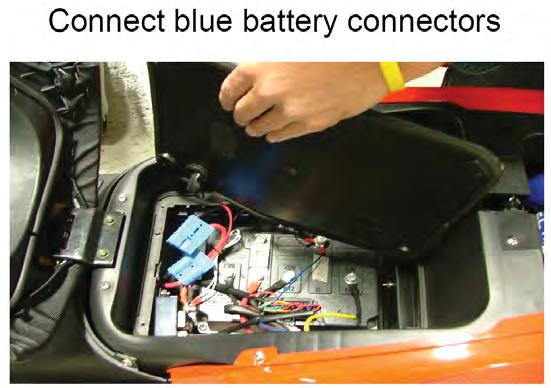
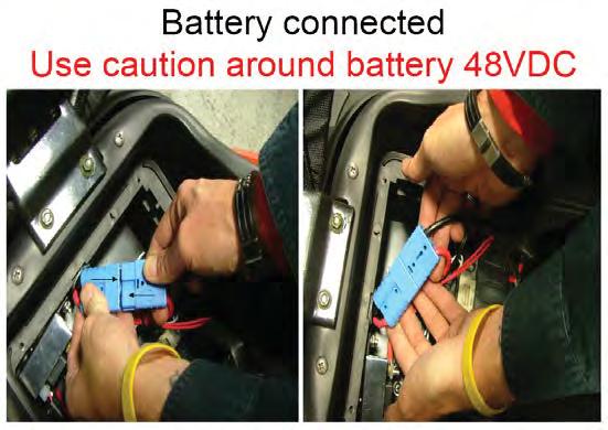
61 SECTION C-14: SEVCON MOTOR CONTROLLER Preparations: Disassemble Seat see Section B-8 Disassemble Left and Right Rear Body Panels see Section B-10 Open the seat and remove Cover of electronic box by using - Phillips screwdriver (old version) - Special secure Torx screwdriver (new version) Turn Key Switch in ON Position Unplug blue Battery Main Connector Turn Key Switch in OFF Position Disconnect Positive Terminals first and remove Main Fuse (1) Then disconnect remaining (Negative) cables and wiring harness 1
62 Unscrew the four Phillips bolts at the base of the Motor Controller to remove the Motor Controller Install new Motor Controller and re-secure with four Phillips bolts Reconnect Negative Cables and Wiring Harness first Then replace Main Fuse and Positive Cables next Reconnect the blue Battery Connection Cable Test functions of Sevcon Motor Controller

 - Special secure Torx screwdriver (new version) Turn Key Switch in ON")
 Disconnect Remaining (Negative) Cables")
63 SECTION C-15: MOTOR Preparations: Disassemble Side Cover see Section B-15 Disassemble Rear Brake see Section B-16 Note: This is the same procedure to replace the Rear Brake Rotor Open the seat and remove Cover of electronic box by using - Phillips screwdriver (old version) - Special secure Torx screwdriver (new version) Turn Key Switch in ON Position Unplug blue Battery Main Connector Turn Key Switch in OFF Position Disconnect Positive Terminals first and remove Main Fuse (1) Disconnect Remaining (Negative) Cables and Wiring Harness 1


64 Unscrew the four Phillips bolts at the base of the Motor Controller to remove the Motor Controller Unscrew the hexagonal nut by using a 8mm open wrench and remove the cable clamp Pull out the motor cable slightly of the electronic box Remark: It is not necessary to remove the parts as it can be seen on the picture Unscrew the motor nut with a special open wrench tool or the Vectrix EM Special spanner socket Take out the motor in the direction of the arrow on the picture.

65 All parts of removed motor Assemble all parts in the other direction Test function of Motor


66 SECTION C-16: BATTERY Preparations: Disassemble Blue Battery Cable Connection see Section C-15 Note: Photos in this section show the Sevcon Motor Controller Housing removed which makes the procedure easier to complete but is not necessary if only the Step-Through panel is removed. Unscrew the hexagon bolts from Battery #1 und #3 Lift up battery #2 and remove it Remark: Batteries are fixed to the battery case with strong velcro. Move the batteries sideways to loosen them from the velcro before remove. Lift up battery #3 and remove it


67 Lift up battery #1 and remove it Lift up battery #4 and remove it Empty battery case for 60AH Assemble all parts in the other direction After assembling: - Measure the voltage of each battery. It should be higher than 12.0 VDC. - Charge the battery before use!
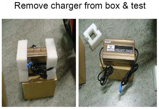
68 SECTION C-17: BATTERY CHARGER Preparations: Open Under Seat Storage Put Key into key hole on the side of the VX-2 to open Under Seat Storage Area. Turn Key to open Under Seat Storage Area
69 Remove Battery Charger from Under Seat Storage Area Plug blue Battery Charger male connector cord into onboard blue Battery Charger female connection. Plug Battery Charger AC connector into a AC main.
70 Turn on Battery Charger Unit power switch. Recharge until Battery Charger Output LED reaches 100% (Yellow). Note: Recharge process can be discontinued and restarted at any time during the charge cycle
 and tighten the nut by using a 14mm open")
71 SECTION D-1: MIRRORS ADJUSTMENT If mirrors are not tightened, remove Left and Right mirrors (refer to Section C, Section C-1) and tighten the nut by using a 14mm open wrench

72 Coarse adjustment: Turn the mirror in the correct position by using the mirror housing The movement should be done with some force, otherwise proceed as figure before


73 Fine adjustment: Move the mirror in the correct position
74 SECTION D-2: HEADLAMP/POSITION LIGHT ADJUSTMENT Headlamp Aiming S-ST Properly aim the headlamp for maximum road illumination and safety. With halogen headlamps, proper aiming is very important. The increased range and power of these lamps make even the slightest variations from the recommended aiming hazardous to approaching motorists. Observe the following conditions when you inspect or adjust the headlamp aim: The scooter is on a level surface. The tires are uniformly inflated to the specified pressure. One person is sitting on the driver's seat. The scooter is in the vertical position. Clean the headlamp before aiming. Follow your state's requirements for headlamp aiming. Headlamp Aiming Location The aiming area should be darkened and large enough to allow for the scooter and an additional 10 m (33 ft), measured from the face of the headlamp to the front of the screen. The floor on which the vehicle rests must be parallel with the bottom of the screen. If the floor is not level, compensate accordingly.
75 Headlamp Aiming Procedure 1. Position the scooter square with the screen, with the headlamp directly over the 10 m (33 ft) reference line (5). 2. Ensure that the vehicle is on a level surface. 3. Draw a horizontal reference line (2) that is in the center of the headlamp. 4. Draw a vertical reference line (1) that is in line with the scooter axis. 5. With the headlamp low beam on the height spot (4) should 9/10th of the headlamp center line (3). Adjusting the headlamp 1. To adjust the light beam up and down turn the right lower side adjustment screw. Clockwise to raise the beam and counterclockwise to lower the beam. 2. To adjust the light beam side-to-side turn the upper left adjustment screw. Clockwise to move the beam to the right and counterclockwise to move the beam to the left.
76 SECTION E-1: INDICATION ON SPEEDOMETER DISPLAY & CONTROLLER LED Indication on LCD Accelerator turn at power up Error Accelerator Volt Stop scooter Battery empty! Error Overcurrent Error Hall sensor Scooter Disabled Error Voltage too high Error High temperature Stop scooter High temperature Low Battery Recharge! Error Sidestand out System Error 01 Controller Reason LED 1 Accelerator is not in zero position 2 Accelerator voltage too high 3 Battery voltage is under 42V permanently 4 Controller defect 5 Hall sensor Malfunction of the motor 6 This messages comes after Stop scooter 7 Battery voltage is over 63V 9 Temperature of the controller is >85 o C 10 Temperature of the controller is >110 o C 11 Battery voltage is under 42V > 15 seconds 6 Side stand switch is active Memory of speedometer defect Solution Release accelerator or turn power OFF and then to ON or proceed to the Accelerator troubleshooting diagram Release accelerator or turn power OFF and then to ON or proceed to the Accelerator troubleshooting diagram Charge the Battery Exchange controller and check motor for short winding against housing Proceed to Hall Sensor check Section 4 of Section E Solve malfunction before this message Use the scooter carefully until message is over, if not, check if the real voltage of the battery is lower than 63V and setting of controller. Or exchange Controller. Wait until temperature goes down under 85 o C. Or exchange Controller Wait until temperature goes down under 110 o C. Or exchange Controller Charge the Battery Check correct function of side stand switch. Exchange Side Stand Switch or controller Exchange Speedometer if message is still there. The LED on the controller flashes if a malfunction is active. Example: LED flash 6 times with 1 Hz, LED off for 2 sec. and starts again. This means: Disable function active
77 SECTION E-2: MALFUNCTIONS - No Top Speed - Check setting of the controller - Check correct function of the accelerator, exchange if needed - No function and no indication on Speedometer - Check Fuse 1 (15A) of the converter - Check voltage on Controller power in line (red and black thick wire) should be higher than 36 V. - Converter broken - Full function but no indication on Speedometer - Check connection of the speedometer - Speedometer broken - No indication of the energy bar on Speedometer - Check Voltage of the battery - Check Voltage on Pin 1 of the speedometer connector. Should be the battery Voltage - Speedometer or controller broken or wire between controller and speedometer - No indication of the consumption bar on Speedometer - Check Voltage of the battery - Check Voltage on pin 1 of the Speedometer connector. Should be the battery Voltage - Speedometer or Controller broken or wire between Controller and Speedometer - No change of battery voltage and mph/kph on Speedometer - Check correct function of MODE switch - Mode switch or Speedometer broken - No indication of speed on Speedometer but motor running is okay - Check if the Voltage on Pin 5 of the speedometer connector. Should change if Motor is turned by hand. Speedometer or Controller broken or wire between Controller and Speedometer
78 SECTION E-3: CHECK OF CHARGER FUNCTION 1. Normal function If the Charger is connected and the indication led on the charger is at 60%, turn on the scooter and the battery voltage indication of the speedometer should show 59.5 V V. During the charging process at 60%, the current should be 10.0 A A, measured with a clamp ampere meter on the brown wire close to the charger DC-plug. If not, check the voltage with a digital voltmeter on the Controller power in line (red and black thick wire). The value should be 59.5 V V. If yes, exchange speedometer, if not, exchange Charger. 2. Charger didn t start Using a Digital Multi meter: - Open the cover seat - Measure on the charger connector of the scooter if the voltage is like the battery voltage indication of the speedometer. If the voltage is zero, check the fuse #2 (30A) of the converter or the connection cable. If the voltage is lower than 33 V check the voltage of each battery and exchange the battery which is lower than 10.0V. - Exchange Charger
79 SECTION F-1: CABLE ASSEMBLY-FRONT BRAKE/INDICATORS + BOM
80
81 SECTION F-2: CABLE ASSEMBLY-FRONT HEADLAMP/HORN + BOM
82
83
84 SECTION F-3: CABLE ASSEMBLY-REAR BRAKE/INDICATORS/TAIL LIGHT/BATTERY/SIDE STAND + BOM
85
86 SECTION F-4: TORQUE LIST FOR BOLTS/NUTS Description Front axle self locking, nut Front brake housing on front shock, bolt Rear brake housing on rear fork, bolt Motor axle, nut Front shock, bolt Brake disc on front rim, bolt Brake disc on motor, bolt Ring on motor, bolt Handle bar, nut Rear fork, left and right nut Front fork, top nut, 32mm Rear shock, top bolt Rear shock, bottom nut Battery, bolt All plastic parts Force 65 NM 30 NM 25 NM 80 NM 70 NM 25 NM 15 NM 15 NM 50 NM 80 NM 60 NM 45 NM 40 NM 25 NM 16 kgf.cm


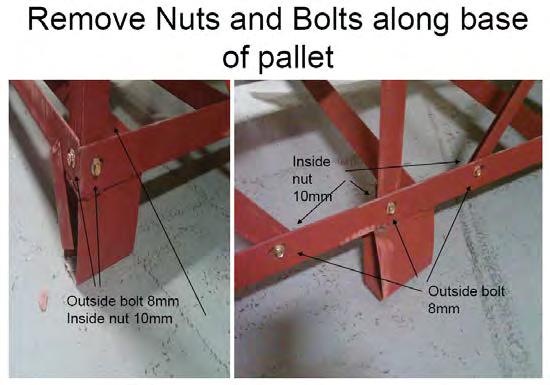
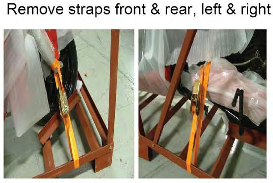
87 SECTION G-1: UNPACKING INSTRUCTIONS


88

89

90

91

92


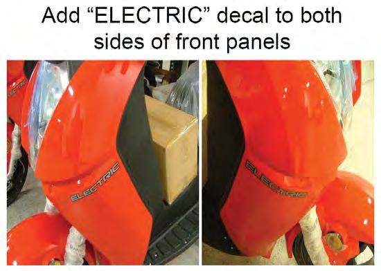
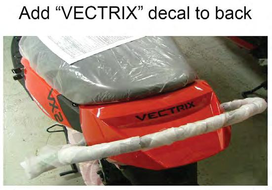
93 SECTION G-2: PREP INSTRUCTIONS


94
95
96
97

98

99
Installation Manual TWM Performance Short Shifter Cobalt SS/SC, SS/TC, HHR SS, Ion Redline and Saab 9-3
 Page 1 Installation Manual TWM Performance Short Shifter Cobalt SS/SC, SS/TC, HHR SS, Ion Redline and Saab 9-3 Please Note: It is preferable to park on a flat surface, as you will have to engage and disengage
Disassembling and Assembling
 Disassembling and Assembling How to disassemble and assemble the controller box 1. Disassembling of controller box Phillips screwdriver, 8# wrench, scissors or penknife. 1) First dismantle the rear bottom
Z TECHNICAL INSTRUCTIONS
 ÍNDICE: Z40 2.0 TECHNICAL INSTRUCTIONS 1.- Error list 2.- Replace the control board 3.- Opening the machine 4.- Replace the power board 5.- Dismantling motor and gear box 6.- Assembly of gear box 7.- Pushing
Slave Cylinder Weep Hole Drilling Procedure
 Slave Cylinder Weep Hole Drilling Procedure Tools Required: T20 Torx Driver T25 Torx Driver T25 Torx Bit with ¼ Ratchet Wrench 4mm Hex Key (Allen wrench) 5mm Hex Key 6mm Hex Key 8mm Hex Key 12mm Hex Key
Detroit Speed, Inc. Electric Headlight Door Kit Corvette P/N: &
 Detroit Speed, Inc. Electric Headlight Door Kit 1968-82 Corvette P/N: 122006 & 122007 The Detroit Speed Inc. Electric Headlight Door Kit replaces the stock vacuum actuated system on all 1968-82 Corvettes.
SR Performance Twin 62mm Throttle Body for GT
 Required Tools: SR Performance Twin 62mm Throttle Body for 2005-2010 GT Flat-head screwdriver Ratchet Small extension 10mm socket 8mm socket T20 Torx bit Needle nose pliers 5mm allen wrench Recommended
SCION tc SECURITY (V5) Preparation
 Preparation") Preparation Part Number: PT398-21070 Kit Contents Item # Quantity Reqd. Description 1 1 2 1 GBS ECU Hardware Bag Contents Item # Quantity Reqd. Description 1 1 V5 Security ECU 2 1 ECU Mounting Bracket
Preparation Part Number: PT398-21070 Kit Contents Item # Quantity Reqd. Description 1 1 2 1 GBS ECU Hardware Bag Contents Item # Quantity Reqd. Description 1 1 V5 Security ECU 2 1 ECU Mounting Bracket
Maintenance Information
 Form 16575334 Edition 1 April 2005 Electric Screwdrivers EL, EP and ET 34V DC Series Maintenance Information Save These Instructions WARNING Maintenance procedures have the potential for severe shock hazard
INSTRUMENT PANEL Toyota Celica DESCRIPTION & OPERATION GAUGES SWITCHES TESTING - GAUGES FUEL GAUGE & WARNING LIGHT
 INSTRUMENT PANEL 1994 Toyota Celica 1994 ACCESSORIES & EQUIPMENT Toyota Motor Sales, U.S.A., Inc. - Instrument Panel Celica * PLEASE READ THIS FIRST * WARNING: Vehicles are equipped with a driver-side
TOYOTA TACOMA TVIP V5
 Preparation Part Number: PT398-35090 Kit Contents Item # Quantity Reqd. Description 1 1 Wire Harness 2 1 Security ECU 3 1 GBS ECU 4 1 Status Monitor/Microphone 5 2 Warning Labels (English) 6 2 Warning
BODY-24, Late Model 944 ( and Newer) Dash Replacement
 Dash Replacement") BODY-24, Late Model 944 (1985.5 and Newer) Dash Replacement Introduction Replacing the dash in a late model 944 is not overly difficult. However, it is very tedious and a lot of patience is required. It's
BODY-24, Late Model 944 (1985.5 and Newer) Dash Replacement Introduction Replacing the dash in a late model 944 is not overly difficult. However, it is very tedious and a lot of patience is required. It's
RANGER 900 POWER STEERING KIT
 RANGER 900 POWER STEERING KIT P/N 2880083 APPLICATION MY14 AND NEWER RANGER XP 900 MODELS IMPORTANT It is strongly recommended that this kit be installed by an authorized Polaris dealer. NOTE Use of this
SPEEDKEY KIT P/N APPLICATION BEFORE YOU BEGIN KIT CONTENTS. Instr Rev Page 1 of 9. GEM e2, e4, e6, el XD
 SPEEDKEY KIT P/N 2883054 APPLICATION GEM e2, e4, e6, el XD BEFORE YOU BEGIN Read these instructions and check to be sure all parts and tools are accounted for. Please retain these installation instructions
TTR225/250 DUAL S PORT K IT I NSTALLATION I NSTRUCTIONS
 TTR225/250 DUAL S PORT K IT I NSTALLATION I NSTRUCTIONS KIT CONTENTS Inspect Your Kit Your kit will include the following items A. TTR225/250 Instructions and Wiring Diagrams Read through the entire instruction
INSTALLATION. Note: Not all parts will be used in the installation of this product. -cont.-
 5005 Fits: 06-up FLHX, 04-up Screamin Eagle Ultra Classic Electra Glide & Screamin Eagle Electra Glide Classic, '97-up FLHT, FLHTC, FLHTCU, FLHR PartS Included 1 Right Driving Light Assembly 1 Left Driving
Deep Space Lighting. VOLVO VNL BI-XENON HEADLAMP KIT Installation Instructions. Tools Needed: #2 Philips screwdriver 10mm socket and ratchet
 Deep Space Lighting VOLVO VNL BI-XENON HEADLAMP KIT Installation Instructions Estimated Installation Time: 15-45 minutes Tools Needed: #2 Philips screwdriver 10mm socket and ratchet Before starting, make
Depress each tab as you pull the bezel off. The bezels are tight. L.H. shown.
 2013-2014 Ford Mustang V6 & Boss 302 Lower Valance Fog Light Kit Parts List: Quantity: Tool List: Fog light & bulb with bracket 2 Flat head & Phillips screwdriver Black bezels 2 Ratchet & Socket set OR
INSTALLATION. DRIVING LIGHTS for FLHT/FLHX/FLHR 5005
 DRIVING LIGHTS for FLHT/FLHX/FLHR 5005 PARTS INCLUDED 1 Right Driving Light Assembly 1 Left Driving Light Assembly 1 Right Driving Light Bracket 1 Left Driving Light Bracket 4 Driving Light Bracket Plugs
Installation Guide Currie Electro-Drive Conversion Kits 2, 3, & 4
 Installation Guide Currie Electro-Drive Conversion Kits 2, 3, & 4 1 Before you start... Use this information to determine whether one of our kits will fit your bike Drawing Ref. Fork Area Leg clearance
LAMPS 8L - 1 LAMPS CONTENTS
 TJ LAMPS 8L - 1 LAMPS CONTENTS BULB APPLICATION... 16 HEADLAMP ALIGNMENT... 5 LAMP BULB SERVICE... 8 LAMP DIAGNOSIS... 1 LAMP SERVICE... 11 LAMP SYSTEMS... 15 LAMP DIAGNOSIS INDEX GENERAL INFORMATION GENERAL
TOYOTA RAV TVIP V3
 Section I Installation Preparation Part Number: 08586-4A872 Section I Installation Preparation Kit Contents Item # Quantity Reqd. Description 1 1 Wire Harness 2 1 Status Monitor 3 1 Piezo Buzzer 4 1 V3
Coil Spring Conversion Kit
 Coil Spring Conversion Kit Land Rover Discovery 3 INTRODUCTION Thank you for your purchase of a coil spring conversion kit from Dunlop Systems and Components Limited, suitable for the Land Rover Discovery
Turn Signal / Horn Kit PN 7101 by All years Polaris RZR 1000 and RZR 900, 900-4, 900 trail, 900S and 900XC STOP - THIS KIT IS DESIGNED
 All years Polaris RZR 1000 and 1000-4 2015 RZR 900, 900-4, 900 trail, 900S and 900XC STOP - THIS KIT IS DESIGNED SPECIFICALLY FOR ALL YEAR AND MODEL POLARIS RZR 1000 AND 1000-4. ALSO THE 2015 POLARIS RZR
Wheel Bearing Replacement Passat TDI
 Rear Bearing/hub assembly replacement This is a fairly straight forward process. Pictures are not necessary for most of this procedure for a person with skills to do this repair. Anyone who thinks they
FENDER ELIMINATOR. Remove axle nut, slide out axle, and drop rear tire away from the fender. (Picture 1)
") TRIUMPH BOBBER Remove axle nut, slide out axle, and drop rear tire away from the fender. (Picture ) Remove () tail light bolts. (Picture ) Unplug stock connectors and remove from underneath the fender.
TRIUMPH BOBBER Remove axle nut, slide out axle, and drop rear tire away from the fender. (Picture ) Remove () tail light bolts. (Picture ) Unplug stock connectors and remove from underneath the fender.
Conflicts: Vehicles without a sunroof Vehicles with a single sunroof
 Toyota Sienna (Dual Sunroof) 2011-10.2 Overhead Video Part Number: 00016-00110 00016-00110-17 Fit Kit 00016-00120 00016-00120-17 Fit Kit Accessory Code: ED5 Conflicts: Vehicles without a sunroof Vehicles
R8 Exhaust Installation Guidelines
 STāSIS Engineering R8 Exhaust Installation Guidelines Exhaust Muffler support bracket bolt to muffler Muffler support bracket to chassis Muffler heat shield screws Heat shield bolt to chassis beneath anti
SMF / DSF / DTF SMF / DSF / DTF 200
 2006 SMF / DSF / DTF 200 1 The drawings in this parts book have been scaled so that parts can be easily recognized. 1 CYLINDER ASSY 2 CYLINDER ASSY Ref # Part # Description 1 410 0001A CYLINDER HEAD COVER
Detroit Speed, Inc. Electric Headlight Door Kit Corvette P/N: &
 Detroit Speed, Inc. Electric Headlight Door Kit 1968-82 Corvette P/N: 122006 & 122007 The Detroit Speed Inc. Electric Headlight Door Kit replaces the stock vacuum actuated system on all 1968-82 Corvettes.
SCION tc 2005 LEATHER STEERING WHEEL Preparation. Part Number: (Silver/Dark Gray)
") Preparation Part Number: 08460 21810 (Silver/Dark Gray) NOTE: Part number of this accessory may not be the same as the part number shown. Kit Contents Item # Quantity Reqd. Description 1 1 Steering Wheel
Preparation Part Number: 08460 21810 (Silver/Dark Gray) NOTE: Part number of this accessory may not be the same as the part number shown. Kit Contents Item # Quantity Reqd. Description 1 1 Steering Wheel
4000 SYSTEM OPERATING MANUAL
 4000 SYSTEM OPERATING MANUAL REV 1.4 COPYRIGHT 1996 Xenotech, Inc. PAGE 1 INSTRUCTIONS FOR REMOVING AND INSTALLING A TYPE XT XENON BULB IN A BL4000 FIXTURE NOTE FAMILIARIZE YOURSELF WITH THE LOCATION AND
GENUINE PARTS INSTALLATION INSTRUCTIONS
 GENUINE PARTS INSTALLATION INSTRUCTIONS 1 DESCRIPTION: 2 APPLICATION: 3 PART NUMBER(S) REQUIRED FOR INSTALLATION: Fog Lamp Kit (AL) Rogue (SV) 999F1 G2000 (Fog Lamp Kit) 4 KIT CONTENTS: Item Qty. Part
Push Start Ignition (05-10 All) Installation
 Installation") Tools Required: Phillips head screwdriver Flat head screwdriver Ratchet 7mm Socket Torx T20 bit Wire strippers/cutters Hand file Needle nose pliers Installation Instructions: Push Start Ignition (05-10
Tools Required: Phillips head screwdriver Flat head screwdriver Ratchet 7mm Socket Torx T20 bit Wire strippers/cutters Hand file Needle nose pliers Installation Instructions: Push Start Ignition (05-10
Property of American Airlines
 Date Maintenance Check list The inspection and preventive maintenance schedule of the Power Stow Rollertrack is as follows: Daily (10 hrs), Weekly (50 hrs.), every 6 months ( hrs.), yearly (1 hrs.) and
PARTS LIST. REPLACEMENT PARTS and ACCESSORIES PREPARATION VN1600. PREPARATION VN1500D and VN800B
 INSTALLATION AND OWNER S MANUAL Light Bar N925 for Installation to: Kawasaki VN1500D&E and VN800B Pages 1,2,3 and 5 Kawasaki VN1600 Pages 1, 4 and 5 PARTS LIST QTY. PART NO. DESCRIPTION 1 N925 Light Bar
INSTALLATION CLAMP-ON FORK MOUNTED DRIVING LIGHTS 5015
 CLAMP-ON 5015 PARTS INCLUDED 2 Driving Lights 2 Side Mount Clamps-43mm/49mm 1 Hardware Kit Including: 2 49mm Spacers 4 43mm Spacers 2 Pivot Dome Washers 2 3/8-16 Serrated Hex Nut 1 Wiring Kit for Driving
INSTALLATION INSTRUCTIONS
 INSTALLATION INSTRUCTIONS Accessory TRIM Application 2009 ACCORD 4-DOOR Publications No. AII 40008 Issue Date JULY 2008 PARTS LIST Steering Wheel Trim (Without Navigation) P/N 08Z13-TA0-100 Right steering
Installation Instructions Console Megashifter
 Installation Instructions Console Megashifter 1968-1969 Camaro Part Number 81035 This B&M Megashifter is designed to fit in the console of a 1968-1969 Chevrolet Camaro. In 1968, these vehicles were equipped
TOYOTA TACOMA 2005 TVIP V5 (RS3200 PLUS) Preparation
 Preparation") Preparation Part Number: 08586 04840 Kit Contents Item # Quantity Reqd. Description 1 1 Wire Harness 2 1 Security ECU 3 1 GBS ECU 4 1 Status Monitor 5 2 Warning Labels 6 1 Owner s Manual 7 1 Warranty Card
Preparation Part Number: 08586 04840 Kit Contents Item # Quantity Reqd. Description 1 1 Wire Harness 2 1 Security ECU 3 1 GBS ECU 4 1 Status Monitor 5 2 Warning Labels 6 1 Owner s Manual 7 1 Warranty Card
3/8 Universal Joint Phillips Head Screwdriver
 Magnetic retrieval tool Pliers 1/4 Ratchet Drive T-35 Torx Socket 3/8 Ratchet Drive 5mm Allen Head Socket Torque Wrench 7-3/8 Drive Extension Flat Head Screwdriver 10mm Socket 8mm Socket 3/8 Universal
J2 Remove sound insulation/knee guard 1 and side panel 2 on center console
 J1 Preparations Drive car forward on a level surface so that wheels are straight. Disconnect battery negative lead. Turn ignition key to position 1 so that steering lock is off. J2 Remove sound insulation/knee
INSTALLATION INSTRUCTIONS
 INSTALLATION INSTRUCTIONS Accessory Application Publications No. BII 24570 P/N 08U97-S3V-210A (BLACK) P/N 08U97-S3V-220A(SADDLE) 2003 MDX Issue Date OCT 2002 PARTS LIST Wood steering wheel 1. Make sure
Go-ped ESR750 / ESR750EX Rear Brake Installation Instructions
 Go-ped ESR750 / ESR750EX Rear Brake Installation Instructions This kit provides all the parts you need to install a rear brake on your ESR750 or ESR750EX. It will not work on an ESR Sport, or other Go-ped
HYDRAULICS. TX420 & & lower. Hydraulic Tandem Pump Removal. 4. Remove the LH side panel (Fig. 0388).
.") TX420 & 425 240000299 & lower 4. Remove the LH side panel (Fig. 0388). Hydraulic Tandem Pump Removal Note: Cleanliness is a key factor in a successful repair of any hydraulic system. Thoroughly clean all
TX420 & 425 240000299 & lower 4. Remove the LH side panel (Fig. 0388). Hydraulic Tandem Pump Removal Note: Cleanliness is a key factor in a successful repair of any hydraulic system. Thoroughly clean all
I N S TA L L AT I O N
 I N S TA L L AT I O N 5008 fits: H-D: '80-Up Electra glide, tour glide, road king, road glide or street glide PartS Included 1 Right Fork Mount Assembly 1 Left Fork Mount Assembly 2 H3 Driving Light Assemblies
LiteDOT Installation Document
 LiteDOT Installation Document This document designed to aid in installation of LiteDOT s on Jeep TJ models, other models are similar. NOTE: Installing LiteDOT s on a Jeep where the 2 necessary mounting
TOYOTA YARIS HATCHBACK TVIP V3 (RS3200) Preparation
 Preparation") Preparation Part Number: 08586-53810 Kit Contents Item # Quantity Reqd. Description 1 1 V3 ECU 2 1 Piezo Buzzer 3 1 Wire Harness 4 1 ECU Mounting Bracket 5 2 Remote Control Transmitter 6 1 Butyl Tape 7
Preparation Part Number: 08586-53810 Kit Contents Item # Quantity Reqd. Description 1 1 V3 ECU 2 1 Piezo Buzzer 3 1 Wire Harness 4 1 ECU Mounting Bracket 5 2 Remote Control Transmitter 6 1 Butyl Tape 7
Audi B6/B7 A4/S4 Rear Wheel Bearing Service Kit
 Audi B6/B7 A4/S4 Installation Tutorial ES2561175 This tutorial is provided as a courtesy by ECS Tuning. Proper service and repair procedures are vital to the safe, reliable operation of all motor vehicles
Luminator Low-Rise Headlight. Designed and built by Radioflyer Innovations
 Luminator Low-Rise Headlight system for C5 Corvette Designed and built by Radioflyer Innovations 1 Tools Required Phillips head screwdriver Flathead screwdriver Torx 15 screwdriver Torx 20 screwdriver
Installation Guide. Kennedy Technology Group, Inc.
 Installation Guide Harley-Davidson Amp Module - Base Kit Kennedy Technology Group, Inc. 614 Ridgeway, Rose Hill, Kansas 67133 - USA voice 316.776.1111 fax 316.776.9035 email:kennedy@cellset.com www.cellset.com
Shelby GT500 Front Fascia Conversion Kit (05-09 All) Item # Installation Time: 1 Day. Required tools:
 Item # Installation Time: 1 Day. Required tools:") Shelby GT500 Front Fascia Conversion Kit (05-09 All) Item #53611 Installation Time: 1 Day Required tools: Phillips Screw driver 10mm Socket + Ratchet/Wrench 8mm Socket + Ratchet/Wrench 5mm Socket + Ratchet/Wrench
Shelby GT500 Front Fascia Conversion Kit (05-09 All) Item #53611 Installation Time: 1 Day Required tools: Phillips Screw driver 10mm Socket + Ratchet/Wrench 8mm Socket + Ratchet/Wrench 5mm Socket + Ratchet/Wrench
TOYOTA COROLLA 2009 TVIP V4 PREPARATION
 PREPARATION Part #: PT398-02080 Conflicts: NOTE: Part number of this accessory may not be the same as the part number shown. Do not install into Manual Transmission Vehicles or Vehicles without RKE systems.
Hayes TrailTrac Kit Installation Guidelines Polaris Rush / Pro-R / Indy
 Models: 2010-2014 Polaris Rush / Pro-R / Indy Packing List 1 Electronic Control Unit (ECU) 1 ECU Velcro, 3 inch 1 Switch face plate 1 Switch face plate adhesive 1 Switch 1 Wiring harness 1 Fully pre-filled
#TL T EA888 GEN 3 FUELING SYSTEM/ INSTALLATION INSTRUCTIONS
 #TL100069 2.0T EA888 GEN 3 FUELING SYSTEM/ INSTALLATION INSTRUCTIONS Notes: These instructions were written for a North American specification MkVII GTI. Other models, like the Golf R, are similar. When
Installation Instructions For The O.CT S4 Boost Gauge
 Installation Instructions For The O.CT S4 Boost Gauge The ultimate power display FROM AND Stratmosphere 28 Boulder Creek Drive Rush, NY 14543 585-533-1777 O.CT Tuning Oberscheider O.CT-Tuning, Reichsstr.
Wolverine Turn Signal / Horn Kit 2102
 All years Yamaha Wolverine STOP - THIS KIT IS DESIGNED SPECIFICALLY FOR ALL YEAR AND MODELS YAMAHA WOLVERINE. IF YOUR MACHINE IS NOT ONE OF THESE MODELS DO NOT PROCEED. Contact Ryco Motorsports or your
INSTALLATION. Note: Not all of the included parts will be used during this installation. -cont.-
 Driving Lights for Road Glide 5007 Fits: 98-up Road Glide PartS Included 1 Right Light Assembly 1 Left Light Assembly 1 Right Mounting Bracket 1 Left Mounting Bracket 1 Hardware Kit Including: 2 Narrow
INSTALLATION INSTRUCTIONS
 INSTALLATION INSTRUCTIONS Accessory Application Publications No. BII 25831-26975 P/N 08U97-S3V-210A (BLACK) P/N 08U97-S3V-220A(SADDLE) 2004 MDX Issue Date MARCH 2004 PARTS LIST Wood steering wheel 1. Make
Part list for Kawasaki H2, 1972
 Part list for Kawasaki H2, 972 . Cylinder head, cylinder. . Cylinder head, cylinder. 9205-049 NUT 0 m/m 2 2 40B400 WASHER-plain 4 m/m 2 3 46E400 WASHER-spring 4 m/m 2 4 92070-036 SPARK PLUG NGK B9 HS 3
STEERING COLUMN - TILT
 STEERING COLUMN - TILT 1993 Toyota Celica 1993 STEERING Toyota - Steering Columns - Tilt Wheel Celica DESCRIPTION & OPERATION Tilt steering wheels incorporate an upper steering shaft, attached by a "U"
Mustang Headlight w/ CCFL Halo (05-09) - Installation Instructions
 - Installation Instructions") Mustang Headlight w/ CCFL Halo (05-09) - Installation Instructions The below installation instructions work for the following products: Chrome Mustang Headlight w/ CCFL Halo (05-09) Smoked Mustang Headlight
Mustang Headlight w/ CCFL Halo (05-09) - Installation Instructions The below installation instructions work for the following products: Chrome Mustang Headlight w/ CCFL Halo (05-09) Smoked Mustang Headlight
GENUINE PARTS INSTALLATION INSTRUCTIONS
 GENUINE PARTS INSTALLATION INSTRUCTIONS 1 DESCRIPTION: 2 APPLICATION: 3 PART NUMBER(S) REQUIRED FOR INSTALLATION: Fog Lamp Kit Rogue w/ AL 999F1 G2000 (Fog Lamp Kit) 4 KIT CONTENTS: Item Qty. Part Description
GENUINE FOG LIGHT INSTALLATION AND USER S INSTRUCTIONS
 GENUINE FOG LIGHT INSTALLATION AND USER S INSTRUCTIONS Thank you for purchasing a genuine Mazda accessory. Before removal and installation, be sure to thoroughly read these instructions. Please read the
XM Adapter Cable (P/N: ) MUST be used for this vehicle.
 MUST be used for this vehicle.") TOYOTA 2013 - Part Number:00016-00076 Code: RX30 XM Adapter Cable (P/N: 00016-00076-10) MUST be used for this vehicle. Conflicts 1. Entune 2. Vehicle s with factory XM radio Kit Contents Item # Qty Description
TOYOTA 2013 - Part Number:00016-00076 Code: RX30 XM Adapter Cable (P/N: 00016-00076-10) MUST be used for this vehicle. Conflicts 1. Entune 2. Vehicle s with factory XM radio Kit Contents Item # Qty Description
TOYOTA CAMRY TVIP V2 (GBS WITH ADD ON)
") Preparation Part Number: 08586-3T930 Kit Contents Item # Quantity Reqd. Description 1 2 Wire Harness (One wire harness is only for RS3200+) 2 1 GBS ECU 3 1 GBS Mounting Bracket 4 1 Microphone Hardware
Preparation Part Number: 08586-3T930 Kit Contents Item # Quantity Reqd. Description 1 2 Wire Harness (One wire harness is only for RS3200+) 2 1 GBS ECU 3 1 GBS Mounting Bracket 4 1 Microphone Hardware
DODGE RAM 2500
 81234007 2014-2015 DODGE RAM 2500 Congratulations - your new LevelTow Helper Springs are quality products capable of improving the handling and comfort of your vehicle. As with all products, proper installation
TOYOTA RAV TVIP V5
 Preparation Part Number: 08586-42810 Kit Contents Item # Quantity Reqd. Description 1 1 Wire Harness 2 1 GBS ECU 3 1 Security ECU Mounting Bracket 4 1 GBS ECU Mounting Bracket 5 1 Status Monitor 6 1 Security
VULCAN 900 Custom. VN900 Custom. Motorcycle Assembly & Preparation Manual
 VULCAN 900 Custom VN900 Custom Motorcycle Assembly & Preparation Manual Foreword In order to ship Kawasaki vehicles as efficiently as possible, they are partially disassembled before crating. Since some
Property of American Airlines
 Date Maintenance Check list This document describes the inspection and maintenance of the Power Stow Rollertrack. Maintenance refers to a time span. The operation hours are shown on the Power Stow Display
09-12 Dodge 4WD /4 Body Lift
 92RC80000 09-12 Dodge 4WD 1500 1 1/4 Body Lift Thank you for choosing Rough Country for all your suspension needs. Rough Country recommends a certified technician install this kit. Attempts to install
STEERING COLUMN - TILT
 STEERING COLUMN - TILT 1994 Toyota Celica 1994 STEERING Toyota - Steering Column - Tilt Wheel Celica DESCRIPTION & OPERATION Tilt steering wheels incorporate a mainshaft, attached by a "U" joint to an
STAGE 1 FIT THE MOTOR WHEEL
 STAGE 1 FIT THE MOTOR WHEEL Stage 1 Requirements Front dropouts = 100mm The width between front fork dropouts should be 100mm. Please also check the gap between forks further up, against the motor diagram
SUT-250-S (These instructions are used for SUT-250-SCLC also)
") SUT-250-S (These instructions are used for SUT-250-SCLC also) Torque wrench, carpenters square, wire cutters, Phillips screwdriver, 7/16, 9/16, and 3/4 combination wrenches, ratchet, 9/16, 3/4, 13/16,
SUT-250-S (These instructions are used for SUT-250-SCLC also) Torque wrench, carpenters square, wire cutters, Phillips screwdriver, 7/16, 9/16, and 3/4 combination wrenches, ratchet, 9/16, 3/4, 13/16,
TOYOTA FJ CRUISER TVIP V5 Preparation
 Preparation Part Number: 08586-36822 Conflicts Do not be installed in vehicles with factory Anti-theft alarm, or Vehicle without Factory Keyless Entry Systems. Recommended Sequence of Application Item
TOYOTA SIENNA TRAILER WIRE HARNESS Preparation
 Preparation Part Number: PT791-08150 (non-se) PT791-08102 (SE only) Kit Contents Item # Quantity Reqd. Description 1 1 Trailer Module Harness 2 1 4-Flat Harness 3 1 Battery Power Wire Harness 4 1 Mounting
TOYOTA CAMRY wo/smart entry TVIP V4 REMOTE ENGINE STARTER (RES)
") Preparation Part Number: 08586-3T950 Kit Contents Item # Quantity Reqd. Description 1 1 Wire Harness 2 1 RES ECU 3 1 BUS ECU 4 1 ECU Mounting Bracket (A) 5 1 ECU Mounting Bracket (B) 6 1 Butyl Tape Hardware
Preparation Part Number: 08586-3T950 Kit Contents Item # Quantity Reqd. Description 1 1 Wire Harness 2 1 RES ECU 3 1 BUS ECU 4 1 ECU Mounting Bracket (A) 5 1 ECU Mounting Bracket (B) 6 1 Butyl Tape Hardware
Conflicts. TOYOTA Prius XM Satellite Radio. Part Number: Code: RX30. Vehicle Service Parts (May be required for reassembly)
") TOYOTA Prius 2013 - Part Number:00016-00076 Code: RX30 Conflicts 1. Entune 2. Vehicle s with factory XM radio Kit Contents Item # Qty Description 1 1 XM Module 2 1 XM Tuner Module 3 1 Wiring Harness 4
TOYOTA Prius 2013 - Part Number:00016-00076 Code: RX30 Conflicts 1. Entune 2. Vehicle s with factory XM radio Kit Contents Item # Qty Description 1 1 XM Module 2 1 XM Tuner Module 3 1 Wiring Harness 4
TOYOTA FJ CRUISER AIR DAM/LIGHT BAR Preparation
 Preparation Part Number: PT278-35071 Kit Contents Item # Quantity Reqd. Description 1 1 Air Dam / Light Bar Hardware Bag 1 Contents Item # Quantity Reqd. Description 1 2 Screw, M6x33mm, Wafer Head 2 2
How to remove and replace the Foonf/Fllo fabric
 How to remove and replace the Foonf/Fllo fabric Remove Headrest Locate the Troubleshooting Tool behind the manual on the back of the car seat, as shown in Figure 1. Raise Headrest to highest position by
Item C& D Not Applicable C
 GENUINE PARTS INSTALLATION INSTRUCTIONS DESCRIPTION: APPLICATION: PART NUMBER(S) REQUIRED FOR INSTALLATION: KIT CONTENTS: LED Fog Lamp Upgrade Rogue Sport 999F1 V4001 A B Item C& D Not Applicable C D Do
User Manual. MB-6000-UD Rev. 1.03
 User Manual MB-6000-UD Rev. 1.03 Table of Contents I. The Controls II. III. IV. Unit Operations A. Folding the Unit B. Folding the Handlebars C. Unlocking and Unfolding D. Precautions and Starting E. Power
TOYOTA CAMRY HYBRID TVIP V5 (RS3200 PLUS) Preparation
 Preparation") Preparation Part Number: 08586-3T940-AA Kit Contents Item # Quantity Reqd. Description 1 1 Wire Harness 3 1 ECU Mounting Bracket NOTE: Part number of this accessory may not be the same as the part number
Preparation Part Number: 08586-3T940-AA Kit Contents Item # Quantity Reqd. Description 1 1 Wire Harness 3 1 ECU Mounting Bracket NOTE: Part number of this accessory may not be the same as the part number
TOYOTA COROLLA 2010 TVIP V4 PREPARATION
 PREPARATION Part #: PT398-02080 or PT398-02100 NOTE: Part number of this accessory may not be the same as the part number shown. Conflicts: Do not install into Manual Transmission Vehicles or Vehicles
TOYOTA TACOMA TVIP V3 (RS3200) Section I - Installation Preparation
 Section I - Installation Preparation") Section I - Installation Preparation Part Number: 08586-04810 Section I - Installation Preparation Kit Contents Item # Quantity Reqd. Description 1 1 Wire Harness 2 1 Status Monitor 3 1 Piezo Buzzer 4
Section I - Installation Preparation Part Number: 08586-04810 Section I - Installation Preparation Kit Contents Item # Quantity Reqd. Description 1 1 Wire Harness 2 1 Status Monitor 3 1 Piezo Buzzer 4
BMW R nine T Tail Tidy Install Guide
 BMW R nine T Tail Tidy Install Guide Thank you for purchasing the Daedalus R nine T Tail Tidy! This guide will help you install it. Page 2: Tail Tidy Installation Page 7: Installing Seat Spacers for use
SUT-450-I ASSEMBLY REQUIREMENTS
 SUT-450-I Torque wrench, carpenters square, wire cutters, Phillips screwdriver, 7/16, 9/16, and 3/4 combination wrenches, ratchet, 9/16,3/4,13/16, and 7/8 sockets. ASSEMBLY REQUIREMENTS *Torque all T-bolt
Ford Focus Zetec SVT Timing Belt
 2000-2004 Ford Focus Zetec SVT Timing Belt Replacement This guide will show you how to replace the timing belt on the 2.0L DOHC Zetec with VCT on a 2002 Ford Focus SVT. This is an interference motor. Written
TOYOTA HIGHLANDER TVIP V2 (GBS ADD ON) Preparation
 Preparation") Preparation Part Number: 08586-48070 Kit Contents Item # Quantity Reqd. Description 1 1 Wire Harness 2 1 GBS ECU 3 1 ECU Mounting Bracket Hardware Bag Contents Item # Quantity Reqd. Description 1 1 Microphone
Preparation Part Number: 08586-48070 Kit Contents Item # Quantity Reqd. Description 1 1 Wire Harness 2 1 GBS ECU 3 1 ECU Mounting Bracket Hardware Bag Contents Item # Quantity Reqd. Description 1 1 Microphone
INSTALLATION INSTRUCTIONS
 INSTALLATION INSTRUCTIONS Accessory Application Publications No. BII 37248 2008 TSX Issue Date JUNE 2007 PARTS LIST 1. Make sure you have the anti-theft code for the radio, then write down the frequencies
RMK HANDLEBAR KIT P/N ; ; APPLICATION BEFORE YOU BEGIN KIT CONTENTS. Verify accessory fitment at Polaris.com.
 RMK HANDLEBAR KIT P/N 2883835; 2883836; 2883837 APPLICATION Verify accessory fitment at Polaris.com. BEFORE YOU BEGIN Read these instructions and check to be sure all parts and tools are accounted for.
SCION xb 2004 SECURITY (V5) Section I Installation Preparation. Part Number:
 Section I Installation Preparation. Part Number:") Section I Installation Preparation Part Number: 08586 52960 Section I Installation Preparation Kit Contents Item # Quantity Reqd. Description 1 1 Wire Harness 2 1 Mounting Bracket 3 1 GBS ECU 4 1 Security
Section I Installation Preparation Part Number: 08586 52960 Section I Installation Preparation Kit Contents Item # Quantity Reqd. Description 1 1 Wire Harness 2 1 Mounting Bracket 3 1 GBS ECU 4 1 Security
LAMPS 8L - 1 LAMPS CONTENTS
 NS LAMPS 8L - 1 LAMPS CONTENTS BULB APPLICATION... 25 EXTERIOR LAMP BULB SERVICE... 9 EXTERIOR LAMP SERVICE... 14 HEADLAMP ALIGNMENT... 5 INTERIOR LAMPS... 18 LAMP DIAGNOSIS... 1 LAMP DIAGNOSIS INDEX GENERAL
INSTALLATION INSTRUCTIONS FUEL SURGE TANK KIT
 INSTALLATION INSTRUCTIONS FUEL SURGE TANK KIT BMW E46 3-Series, Excl Convertible Document: 19-0056 Support: info@radiumauto.com Relieve fuel pressure in vehicle before beginingthe installation. Disconnect
The steering column is of a modular construction and features easy to service electrical switches.
 file://c:\tso\tsocache\vdtom_5368\svk~us~en~file=svkb4a01.htm~gen~ref.htm Page 1 of 3 Section 11-04A: Steering Column, Ranger DESCRIPTION AND OPERATION 1997 Ranger Workshop Manual Steering Column NOTE:
OEM Cruise Control Installation in GMC/Chevy NBS trucks
 OEM Cruise Control Installation in 99-02 GMC/Chevy NBS trucks May 2008 ~ Rampage_Rick Having just installed factory cruise control in my 00 Sierra, I thought I d share the fun. I followed the steps outlined
AmTryke Adult Recumbent Model JT2000 #50-FC-2000
 AmTryke Adult Recumbent Model JT2000 #50-FC-2000 TOOLS Needed for Assembly 5 mm Allen Wrench 8 mm Socket or Wrench 10 mm Socket or Wrench 14 mm Socket or Wrench 15 mm Socket or Wrench 22 mm Socket or Adjustable
Lubecore International Automated Lubrication System Inspection, Service & Repair - MLP/Spyder Pump MKI & MKI Rev-A
 Lubecore International Automated Lubrication System Inspection, Service & Repair - MLP/Spyder Pump MKI & MKI Rev-A System Inspection MKI & MKI Rev-A Spyder System Check Check for: Conclusion of Review
K T M E X C / M X C D U A L S P O R T K I T I N S T A L L A T I O N
 K T M E X C / M X C D U A L S P O R T K I T I N S T A L L A T I O N K T M D U A L S P O R T K I T I N S T A L L A T I O N KIT CONTENTS Inspect Your Kit Your kit will include the following items A. KTM
REMOVING CYLINDER HEAD COVER (VALVE COVER) - AS OF MY 2004 (CAYENNE TIP, CAYENNE MAN) > PRELIMINARY WORK > PRELIMINARY WORK
 - AS OF MY 2004 (CAYENNE TIP, CAYENNE MAN) > PRELIMINARY WORK > PRELIMINARY WORK") Page 1 of 9 CYLINDER HEAD, VALVE DRIVE 15 82 21 REMOVING CYLINDER HEAD COVER (VALVE COVER) - AS OF MY 2004 (CAYENNE TIP, CAYENNE MAN) > PRELIMINARY WORK > PRELIMINARY WORK 1. Remove engine compartment
Page 1 of 9 CYLINDER HEAD, VALVE DRIVE 15 82 21 REMOVING CYLINDER HEAD COVER (VALVE COVER) - AS OF MY 2004 (CAYENNE TIP, CAYENNE MAN) > PRELIMINARY WORK > PRELIMINARY WORK 1. Remove engine compartment
Your G3 buggy is fitted with three switches on the front part of the body:
 CONTENTS Buggy operation... 3 General Maintenance... 5 Technical Maintenance... 6 Front wheel bearing replacement... 6 Rear wheel bearing replacement... 7 Chain replacement... 8 Chain Adjustment... 9 Brake