Auto Sentry-eXP Maintenance. Revised 12/21/07
|
|
|
- Elijah Wells
- 5 years ago
- Views:
Transcription


1 Auto Sentry-eXP Maintenance Revised 12/21/07
2 Maintenance Procedures for Auto Sentry exp Bill Dispenser Credit Card Reader Bill Acceptor
3 Bill Dispenser Maintenance Bill Dispenser Problem / Cause Bill Dispenser Error Codes Cleaning Pick Assembly Feed Rollers Cleaning the Bill Dispenser Belts Cleaning and Testing Sensors Bill Dispenser Removal Procedure MDS Sensor Adjustment Procedure Bill Cassette and Cavity Checks
4 Fujitsu Bill Dispenser Problem / Cause High Bill rejection rate Place only dollar bills in good condition in Bill Dispenser cartridge Stack dollars neatly in cassette Clean MDS sensor area including metal rollers and clear Mylar scrapers Check MDS sensor reading in RAS mode 60 (E7 +4) E3 through EB Clean BPS sensors and prism Tighten white rails in Bill Dispenser cavity Bill jams/miss feeds in bill cassette cavity Clean black pick wheels and green feed rolls Clean PS1 sensor and prism Check Bill Dispenser cassette metal tab on frame Tighten white rails in Bill Dispenser cavity Rejected bills not detected Clean Reject sensor Jams at Bill Dispenser feed out Check that feed out rolls turn when green wheel is turned Clean CPS sensor Replace worn anti-static brush Jams (general) Clean all feed rolls, feed belts, and Pick wheels Check drive belt tension Check Sensor Health Screen in Diagnostics and clean sensors if necessary Clean clock wheel and sensor
5 Auto Sentry exp Error Code Reporting for the Bill Dispenser 1800 PS1 Sensor No bills in cassette- Pick Assembly Open? 7001 PS1 Sensor Bill jammed in PS1 sensor 7006 BPS Sensor Check for Bill in BPS sensor 7009 CPS Sensor Check for Bill in CPS sensor 700B RJS Sensor Bill remaining RJS sensor 7081 BPS Sensor Bill remaining between PS1 and BPS sensor This error indicates that there may be a Bill jammed in the PS1 sensor located behind the bill cassette Jam occurred between PS1 and BPS Look for a Bill blocking the PS1 sensor 782C RJS Sensor PS1 Bill remaining after completion of cleaning jam Check for a jammed Bill in the area of the BPS sensor and remove if found Check for a jammed Bill in the area of the BPS sensor PS1 Bill detected BPS Bill remaining after completion of cleaning 7A01 - Open up the Bill Dispenser and Clear the jam between BPS and CPS 7A02 - Open the Bill Dispenser and Clear the Jam near CPS Sensor
 F800 PS1")
6 Auto Sentry exp Error Code Reporting for the Bill Dispenser 7A2B - Check the CPS sensor and put it back in its position 7A3A - Check for remaining Bill in dispense path (around BPS) 7B00 - Open the Bill Dispenser and remove the jammed Bill between BPS - RJS sensor 7B30 - Check RJS sensor to make sure it is back in its normal place 7B3C - Remove any Bills in dispense path (around RJS) F800 PS1 Sensor Error Clean sensor or replace F805 BPS Sensor Error Clean sensor or replace F808 CPS Sensor Error Clean sensor or replace F809 RJS Sensor Error Clean sensor or replace 8200 BPS Sensor Bill Read Error Long Bill BPS Sensor Bill Read Error Short Bill 8501 PS1 Sensor - Count mismatch (CPS was turned ON when there was no Bill.) 8800 CPS Sensor Count mismatch (Number of requested notes = number of notes identified as normal = number of notes that passed through CPS does not hold.) 8801 CPS Sensor 8803 CPS Sensor - Count mismatch (Bill passed through CPS while clearing jam.) B5xx RJS Sensor Exxx PCB Replacement
")
7 Checking Bill Dispenser Health Pressing either End of Day Switch will bring up the Service Unit (Jack Pot) Screen.
 Screen.")
8 Bill Dispenser Heath Check the Bill Dispenser Sensor Health periodically. The individual Sensor Health can be checked from the Service Unit (Jack Pot) Screen. Touch the Diagnostics Button

9 The individual Sensor Health is indicated via a traffic light display. All sensors should have a green light. Yellow light indicates that the sensor requires maintenance soon. Red light indicates immediate maintenance is required. Bill Dispenser Heath


10 Cleaning Pick Assembly Rollers Remove Bill Cassette from Bill Dispenser to access the Pick Rollers Remove Bill Cassette
11 Cleaning Pick Assembly Rollers Clean the rollers by placing a soft alcohol (isopropyl) dampened cotton cloth against each individual roller while rotating one of the black rollers in an upward direction


12 Cleaning Pick Assembly Rollers Clean the remaining two rollers by placing a soft alcohol dampened cotton cloth against each individual roller Turn the large green wheel located on the left side of Bill Dispenser in a clockwise direction while applying pressure to rollers


13 Move the three belts off the center of their respective black rollers. Remove any dirt accumulation on the rollers with isopropyl alcohol Move all belts back to their proper position Turn large green wheel to ensure belts are tracking properly Belt Roller Cleaning


14 Cleaning the Lower Set of Bill Dispenser Belts Mark each of the three belts to determine full belt rotation With the Bill Cassette removed, reach in through the cassette cavity with cleaning cloth Clean the lower set of belts by pinching each of the three belts with a soft alcohol-dampened cotton cloth while rotating the large green wheel Video demonstration on next slide

15 Cleaning the Lower Bill Dispenser Belts Clean the lower set of belts by pinching each of the three belts with a soft alcohol dampened cotton cloth while rotating the large green wheel


16 Cleaning the Upper Set of Bill Dispenser Belts Mark each of the three belts to determine full belt rotation Clean the upper Bill Dispenser belts by pinching each of the three belts with a soft alcohol-dampened cotton cloth while rotating the large green wheel
17 Cleaning the Output Belts The three belts can be cleaned by placing a soft alcohol-dampened cotton cloth against each of the belts while rotating the large green wheel Viewed from the top (1 of 3 belts shown) Viewed looking in from Bill Cassette cavity


18 Feed out Idler Rollers Ensure both feed out idler rollers turn when turning the large green wheel. If one or both do not turn, reform metal spring tentioners to obtain better contact.
19 Cleaning Clock Wheel With canned air, blow off any dust that may have accumulated on the clock wheel and both sides of sensor The clock wheel can be rotated by turning the large green wheel Sensor
20 Testing Bill Dispenser Sensors The Bill Dispenser sensors can be tested by placing the Bill Dispenser in a diagnostic test mode. This diagnostic test mode is called RAS mode. Follow the instructions in the blue area to test the individual sensors For Example To Test the CPS Sensor Enter RAS Mode Press SW1 5 times until 5 is displayed Press SW2 twice until 2 is displayed Press ST twice to enter test mode Look for upper right segment on the units display to change state when sensor is blocked (illuminated to Not illuminated)
21 Entering RAS Mode (Diagnostic Sensor Test) Press SW1, SW2, and ST at the same time Display will go from 00 to 8.8. to 0.0. Release all switches Enter diagnostic code using SW1(Ten s) and SW2 (Units)
22 Testing Bill Dispenser Sensors For Example To Test the CPS Sensor Enter RAS Mode Press SW1 5 times until 5 is displayed Press SW2 twice until 2 is displayed Press ST twice to enter test mode Look for upper right segment on the units display to change state when sensor is blocked (illuminated to Not illuminated) Sensor Tested RAS Mode Diagnostic Number PS1 51 RJS 52 CPS 52 BPS 5A MDS 60 Adjust to + 8 E0,E1,E2,E3,E4,E5,E6,E7,E8,E9,EA,EB,EC,ED,EF
23 Testing Bill Dispenser Sensors For Example To Test the CPS Sensor Enter RAS Mode Press SW1 5 times until 5 is displayed Press SW2 twice until 2 is displayed Press ST twice to enter test mode Look for upper right segment on the units display to change state when sensor is blocked (illuminated to Not illuminated) CPS Sensor Unblocked Sensor Tested RAS Mode Diagnostic Number PS1 51 RJS 52 CPS 52 BPS Example of CPS Sensor Test MDS 60 5A Adjust to + 8
24 Testing Bill Dispenser Sensors For Example To Test the CPS Sensor Enter RAS Mode Press SW1 5 times until 5 is displayed Press SW2 twice until 2 is displayed Press ST twice to enter test mode Look for upper right segment on the units display to change state when sensor is blocked (illuminated to Not illuminated) CPS Sensor Blocked Sensor Tested RAS Mode Diagnostic Number PS1 51 RJS 52 CPS 52 BPS Example of CPS Sensor Test MDS 60 5A Adjust to + 8
25 Testing Bill Dispenser Sensors For Example To Test the CPS Sensor Enter RAS Mode Press SW1 5 times until 5 is displayed Press SW2 twice until 2 is displayed Press ST twice to enter test mode Look for upper right segment on the units display to change state when sensor is blocked (illuminated to Not illuminated) CPS Sensor Unblocked Sensor Tested RAS Mode Diagnostic Number PS1 51 RJS 52 CPS 52 BPS Example of CPS Sensor Test MDS 60 5A Adjust to + 8
26 Testing Bill Dispenser Sensors For Example To Test the CPS Sensor Enter RAS Mode Press SW1 5 times until 5 is displayed Press SW2 twice until 2 is displayed Press ST twice to enter test mode Look for upper right segment on the units display to change state when sensor is blocked (illuminated to Not illuminated) CPS Sensor Blocked Sensor Tested RAS Mode Diagnostic Number PS1 51 RJS 52 CPS 52 BPS Example of CPS Sensor Test MDS 60 5A Adjust to + 8
27 Testing Bill Dispenser Sensors For Example To Test the CPS Sensor Enter RAS Mode Press SW1 5 times until 5 is displayed Press SW2 twice until 2 is displayed Press ST twice to enter test mode Look for upper right segment on the units display to change state when sensor is blocked (illuminated to Not illuminated) CPS Sensor Unblocked Sensor Tested RAS Mode Diagnostic Number PS1 51 RJS 52 CPS 52 BPS Example of CPS Sensor Test MDS 60 5A Adjust to + 8
28 Testing Bill Dispenser Sensors For Example To Test the CPS Sensor Enter RAS Mode Press SW1 5 times until 5 is displayed Press SW2 twice until 2 is displayed Press ST twice to enter test mode Look for upper right segment on the units display to change state when sensor is blocked (illuminated to Not illuminated) CPS Sensor Blocked Sensor Tested RAS Mode Diagnostic Number PS1 51 RJS 52 CPS 52 BPS Example of CPS Sensor Test MDS 60 5A Adjust to + 8
29 Testing Bill Dispenser Sensors For Example To Test the CPS Sensor Enter RAS Mode Press SW1 5 times until 5 is displayed Press SW2 twice until 2 is displayed Press ST twice to enter test mode Look for upper right segment on the units display to change state when sensor is blocked (illuminated to Not illuminated) CPS Sensor Blocked Sensor Tested RAS Mode Diagnostic Number PS1 51 RJS 52 CPS 52 BPS Example of CPS Sensor Test MDS 60 5A Adjust to + 8
 Sensor Tested RAS Mode Diagnostic Number PS1 51 RJS 52 CPS 52 BPS 5A MDS 60 Adjust to")
30 Testing Bill Dispenser Sensors For Example To Test the CPS Sensor Enter RAS Mode Press SW1 5 times until 5 is displayed Press SW2 twice until 2 is displayed Press ST twice to enter test mode Look for upper right segment on the units display to change state when sensor is blocked (illuminated to Not illuminated) Sensor Tested RAS Mode Diagnostic Number PS1 51 RJS 52 CPS 52 BPS 5A MDS 60 Adjust to + 4 E3,E4,E5,E6,E7,E8,E9,EA,EB
31 Exiting RAS Mode Press SW1, SW2, and ST at the same time Display will go from 0.0. to 8.8. to 00 Release all switches
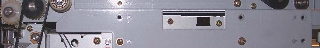
32 Sensor Location TOP FRONT


33 CPS Sensor Secondary Counting Sensor Clean upper sensor with soft cloth Clean lower sensor with Q-Tip Viewed from top
 Phillips head")
34 CPS Sensor Cleaning Improved Access and Visibility Remove the two (2) Phillips head screws securing the CPS sensor Bracket Carefully flip bracket over as shown Clean both sensor faces with a Q-Tip Reinstall CPS bracket with the tabs falling into the frame detents and secure with two (2) Phillips head screws


35 Measures bill thickness Blow compressed air to clean sensor area MDS Sensor (Bill Thickness Sensor) Viewed from top
36 It is imperative that both sets of rollers are clean to prevent high spots which would cause good bills to be rejected Sensor Location TOP MDS Sensor Bill thickness sensing is accomplished by a bill traveling between two sets of rollers FRONT
37 MDS Exit Roller cleaning Make sure metal rollers located in the top near MDS Sensor are clean The rollers can be cleaned by rotating the green turn knob while holding a Q-Tip saturated with alcohol held against the rollers as they turn. MDS Sensor


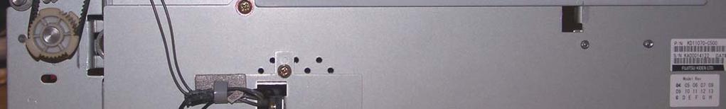
38 MDS Exit Roller cleaning Make sure the upper and lower metal rollers located in the top rear of the Bill Dispenser near the MDS sensor are clean Access to the area can be improved by removing two Phillips head screws from a cross member in the top rear of the Bill Dispenser Lift the cross member up The rollers can be cleaned by rotating the green turn knob while holding a Q-Tip saturated with alcohol held against the rollers as they turn Clean upper and lower clear plastic scrapers Reinstall cross member after cleaning Top right rear of BD MDS Sensor Top left rear of BD Upper Roller Lower Rollers


39 MDS Sensor Roller cleaning Make sure metal rollers located in the top near MDS sensor are clean Both clear plastic Mylar roller scrapers for the upper and lower rollers must be free of dirt Clean with alcohol Upper Mylar scraper MDS Sensor Viewed from top of Bill Dispenser Lower Mylar scraper


 Viewed")

40 Clean both sensor faces with a soft cloth (Bill Dispenser may need to removed. Removal procedure is outlined later in this slide presentation) Viewed from back Front facing down BPS Sensor (Skew and Length Sensor)

41 The light return path via the clear prism must be cleaned Cleaning can be performed by first blowing out the area with canned air Using a Q-tip, clean both top areas of the prism. Alcohol can be used to remove dirt followed by a mild detergent. BPS Sensor
 Clean both sensor faces with a")


42 RJS Sensors (Reject Full Counting Sensor) Clean both sensor faces with a soft cloth Remove the Bill Dispenser cartridge. The RJS sensors are located directly in line with the cut out on the bill dispenser. The sensors can be found 3 and 6 inward from the front of the dispenser. Viewed from bottom of bill dispenser cavity Bill Cartridge has been removed Top of Bill Dispenser facing down FRONT


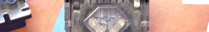
43 PS1 Sensor (Primary Counting Sensor) Blow compressed air in and around sensor area with feed in Closed position Insert Q-Tip through U shaped access holes to clean surface of clear prism. Clean sensor faces with Q-tip. The Q-tip will clean the prism surface after being inserted 1½ on left and 2 1 /4 on right. Rotate Q-Tip when pulling out to prevent cotton from being pulled off tip Viewed with Bill Dispenser upside down Viewed with Bill Dispenser Cassette removed Photo sensor with Prism Q-Tip shown inserted

44 PS1 Sensor Cleaning Clean both sensor windows that are located on the Close tab facing the green feed wheels in the feeder assembly with a Q-tip Viewed with Bill Dispenser upside down Viewed with Bill Dispenser right side up Cassette removed Clean both rectangular window areas by moving Q-Tip up and down in areas shown Clean other side of window surface with Q-Tip as shown - moving Q-Tip side to side


45 PS1 Sensor Cleaning Blow compressed air in from direction of yellow arrows into area highlighted in the red rectangle Viewed with Bill Dispenser cassette removed


46 PS1 Sensor PSI Sensor Prism location Viewed from back of Bill Dispenser
47 PS1 Sensor Cleaning If sensing problems still exist with the PS1 sensor after the cleaning procedures have been performed then follow the addition cleaning procedures described in the next several slides Tools required Magnetic Phillips head screwdriver Nut driver set Soft cloth


48 Removing the Bill dispenser Power OFF Auto SentryeXP Remove the nut and bolt on each side of the Bill Dispenser


 - Unclip")


49 Removing The Bill Dispenser Unplug top wiring harness (1) - Mark top of connector Remove bottom wiring harness (2) - Mark top of connector Unclip the wire harness clamp if lower harness is routed through it (3) Remove screw securing ground strap (braided wire with yellow loop end (4) (4) (1) (2) (3)
50 Removing the Bill Dispenser Spread the wiring track tabs on the retaining clip (1) outward to release the wiring track casing (2) (1) (1) (2)

51 PS1 Sensor Cleaning 1. Turn power off to AutoSentry-eXP 2. Remove Bill Dispenser cartridge 3. Remove Bill Dispenser assembly from AutoSentry-eXP slide out tray 4. Turn Bill Dispenser assembly upside down as shown
52 PS1 Sensor Cleaning Remove two screws from Close tab bracket Push up on Open tab to release
53 PS1 Sensor Cleaning Both PS1 sensors can now be easily seen With a damp cloth clean both black square sensors with round sensor faces


54 Clean translucent viewing window with compressed air followed by a slightly water dampened Q-Tip PS1 Sensor Cleaning
55 PS1 Sensor Cleaning Close spring loaded mechanism with your hand by reaching in and pushing up as shown


56 PS1 Sensor Cleaning Reinstall the two screws from Close tab bracket Reinstall Bill Dispenser assembly
57 Reinstalling Bill Dispenser Reinstall wiring harness track into retaining tabs Route the two wire harnesses and ground strap along left side of Bill Dispenser Plug in both wire harnesses into their respective plug jacks. Be careful to plug them in correctly. They should only fit one way correctly.

58 Reinstalling Bill Dispenser Fasten ground strap Reinstall the hardware securing the Bill Dispenser Turn AutoSentry-eXP power on
")


59 Bill Cassette Check There are three (3) gray colored magnets located in the lid of the Bill Cassette. They can be viewed from the top through access holes. Holes a, b, c should appear gray and the d hole should be open

 When reinstalling Reinstall access cover plate the cover ensure that the cover tab")
60 Bill Cassette Check The magnet retainer should be checked periodically to ensure the that the thumb screws are tight Turn the access cover thumb screw counter-clockwise to remove cover Check both thumb screws on the magnet retainer to ensure that they are tight. (turn in clockwise direction) When reinstalling Reinstall access cover plate the cover ensure that the cover tab is inserted into the slot Removing access cover Remove cover Check the thumb screws
61 Level 2 Bill Dispenser Maintenance Additional adjustment and cleaning procedures are outlined in the following slides if problems still exist in the Bill Dispenser. Proceed only with Level 2 adjustments if directed by Support Removing the Pick Assembly PS1 sensor - Pick Assembly Cleaning MDS sensor adjustment (bill thickness) Checking Bill Cassette latch tab

62 Level 2 Removing the Pick Assembly Perform this procedure only when directed by ICS Support Click the image to start video


63 Level 2 Pick Assembly Cleaning
64 Level 2 Removing the Open Tab Cross Member Remove one screw from each side of the Pick Assembly


65 Level 2 Removing the Open Tab Cross Member Carefully remove the cross member and set it down as shown.
66 Level 2 Opening the Close Tab Area Remove the two screws on the Close Tab and fold down


67 Level 2 Clean the entire area Blow off the Dust Clean all rollers Metal Rubber
68 Level 2 Cleaning the Bill Restrictor Area The ball bearing rollers can be easily moved and cleaned by pivoting away from the bill restrictor rollers Bill Restrictors Ball Bearings


69 Level 2 Cleaning the PS1 Sensors Wipe Clean both PS1 sensors Warning: Do not use alcohol to clean the plastic sensors.
70 Level 2 Clean the Pick Assembly Rollers Clean each of the Black Pick Rollers individually by holding a alcohol dampen rag against one roller while the other is rotated in direction shown Black Pick Roller


71 Level 2 Clean the Pick Assembly Rollers Clean the Outer Green rollers on each side by holding a alcohol dampen rag against each green roller as the black pick roller is rotated in direction shown Black Pick Roller


72 Level 2 Clean the Pick Assembly Rollers Clean the remaining two center green rollers by rotating the sprocket while holding a alcohol dampen rag against each green roller


 2")
73 Level 2 Cleaning the Ball Bearing Rollers Clean the Ball Bearing Rollers (1) with alcohol Large deposits can be scraped off by rotating the bearing while holding the bearing against the metal scraper (2) 2 1

74 Level 2 The Prism faces can be easily viewed and cleaned with a Q-Tip Clean the Black Translucent window on both sides Cleaning the Prism
75 Level 2 Bill Restrictor Area Reassembly The ball bearing rollers need to be closed against the bill restrictors before proceeding with the closure of the Close Tab Area Shown with rollers closed
76 Level 2 Reassembly Fold back the sensor assembly Squeeze the sensor assembly and Close Tab together Replace both small screws 3 1 2


77 Level 2 Reinstalling the Open Tab Reinstall the Open Tab Cross member by keeping the treaded tabs within the Pick Assembly bracket Ensure that the tabs fit in the cutouts on the frame Reinstall both larger screws; one on each side Cross Member


78 Level 2 Reinstall the Pick Assembly

79 Level 2 MDS Sensor Adjustment Before performing adjustment perform upper and lower roller as well as Mylar scraper cleaning procedures outlined on previous slides Failure to perform the proper cleaning procedures will result in an inaccurate adjustment of the MDS sensor
 Adjust MDS sensor to achieve a value of E7 +4 Exit RAS mode after")
80 Level 2 MDS Diagnostic Code Entry Adjustments to the MDS sensor should only be made by an ICS Technician unless authorized by ICS Support Enter RAS mode MDS Sensor diagnostic code 60 Enter code by pressing the SW1 switch until a 6 appears in the ten s display Press ST switch twice to start test A code will be displayed (Ex) Adjust MDS sensor to achieve a value of E7 +4 Exit RAS mode after adjustment is within specifications


 2.")
")

Turn Slotted screw on right side")
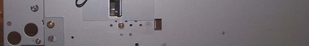
81 Level 2 Adjusting MDS Sensor Adjustments to the MDS sensor should only be made by an ICS Technician unless authorized by ICS Support 1. Loosen both upper Phillips head screws through the access in the Bill Dispenser frame (Only slightly loosen the screws) 2. Turn slotted screw very slowly until a reading close to E7 is shown on diagnostic display (+ 4 tolerance) 3. Tighten Phillips head screw (1) MDS sensor bracket Left side view Loosen the top Phillips head screw only (1)Loosen the top Phillips head screw on both sides slightly (2)Turn Slotted screw on right side very slowly until a reading close to E7 is shown on diagnostic display


82 Level 2 MDS Sensor Adjustment Check After making the MDS sensor adjustment a final check must be performed to ensure that the adjustment has been performed correctly Slide the Bill Dispenser out so that the metal extensions can be accessed. Press down lightly on one of the metal extensions The value on the display should change in a downward direction i.e.: E7, E6, E5, E4, - df, d9, etc. Click on video on right to view display change as metal extension is pressed down


83 Level 2 MDS Sensor Adjustment Check An additional check can be performed by inserting a Dollar Bill at the Bill Dispenser exit Rotating the large green wheel from front to back will feed the dollar bill back into the Bill Dispenser toward the MDS sensor The display should change from E7 to a lower value. i.e.: CC, Cd, CE, etc. Click on the video to the right to view the procedure Feed dollar bill over the MDS sensor as shown No dollar bill over MDS sensor With dollar bill over MDS sensor


84 Level 2 Exiting RAS Mode Press SW1, SW2, and ST at the same time Display will go from 0.0. to 8.8. to 00 Release all switches Important! Make sure display is in run mode [0][0] when complete

85 Level 2 Checking the Bill Cassette Cavity Inspect that the tab is at a 90 0 angle with the frame Reform if necessary Left Side view Tab Inspect white rails on each side of Bill Dispenser cavity and tighten screws if found to be loose


86 Level 2 Proper Drive Belt Configuration (shown with cover removed)
87 Credit Card Reader Maintenance Removing Foreign Objects Credit Card Reader Cleaning Procedure


")

88 Credit Card Reader Maintenance Check for foreign objects in card reader cavity Paper or credit card label material is often found in the area of the sensor(1) and within the clear cavity of the credit card reader(2) (1) (2)


89 Credit Card Reader Removing Debris A paper clip or a piece of wire can be reformed and utilized to remove small pieces of paper from inside of Credit Card Reader Form a paper clip or wire to extract piece of paper

90 Credit Card Reader Foreign Object Removal
91 Credit Card Reader cleaning procedure Insert the alcohol moistened Credit Card Cleaner Card into the credit Card Reader Pull out and reinsert the card 7 to 8 times Credit Card Cleaner
92 Credit Card Reader cleaning procedure Insert the alcohol moistened Credit Card Cleaner Card into the credit Card Reader Pull out and reinsert the card 7 to 8 times Credit Card Cleaner
93 Credit Card Reader cleaning procedure Insert the alcohol moistened Credit Card Cleaner Card into the credit Card Reader Pull out and reinsert the card 7 to 8 times Credit Card Cleaner
94 Credit Card Reader cleaning procedure Insert the alcohol moistened Credit Card Cleaner Card into the credit Card Reader Pull out and reinsert the card 7 to 8 times Credit Card Cleaner
95 Credit Card Reader cleaning procedure Insert the alcohol moistened Credit Card Cleaner Card into the credit Card Reader Pull out and reinsert the card 7 to 8 times Credit Card Cleaner
96 Credit Card Reader cleaning procedure Insert the alcohol moistened Credit Card Cleaner Card into the credit Card Reader Pull out and reinsert the card 7 to 8 times Credit Card Cleaner

97 Credit Card Reader cleaning procedure Insert the alcohol moistened Credit Card Cleaner Card into the credit Card Reader Pull out and reinsert the card 7 to 8 times Credit Card Cleaner
98 Credit Card Reader SUN cleaning procedure Important!!! Close the right Auto Sentry-EXP door prior to checking the operation of the Credit Card Reader. Stray sunlight will negatively impact its proper operation


99 Bill Acceptor Maintenance Bill Acceptor Cleaning Procedure
100 Bill Acceptor Status LED
101 Bill Acceptor Status LED
102 Bill Acceptor Status LED
103 Bill Acceptor Status LED
104 Bill Acceptor Status LED


105 Bill Acceptor Connector Pin outs Cartridge Side


")

106 Bill Acceptor Maintenance Remove Bill Acceptor Cartridge by depressing Blue release button (1) Slide Bill Acceptor Cartridge (2) to (2) right and lift up to remove (1)


107 Bill Acceptor Maintenance Clean clear surfaces with a soft cloth moistened with a mild detergent solution Clean white rollers with a damp cloth gently scrape white rollers if necessary. Ensure that rollers move freely
108 Bill Acceptor Maintenance Reinstall Bill Acceptor Cartridge (1) with white tab facing blue release tab on reader Slide Bill Acceptor Cartridge (2) to left until it snaps in place (1) (1) (2)
109 Maintenance Procedures for Auto Sentry exp Training complete! Thank you for your participation 1349 Jacobsburg Road - Wind Gap, PA
Engineering the Future of Payment Solutions
 Subject: Preventative Maintenance and Cleaning Procedure for MSM Bill Validator Objective: To outline a procedure to ensure your Cashcode bill validator continues to operate as per factory specifications
Maintenance Adjustments
 4 Maintenance and Adjustments Chapter Contents Cleaning the Printer and Paper Handling Accessories..... 158 Cleaning the HP Digital Copier....................... 161 Cleaning ADF and Glass............................
Replacing the pick rollers P.N X
 Instruction Sheet Replacing the pick rollers P.N. 118-9717-0X For assistance while replacing the pick rollers, contact you local Tektronix representative. In the U.S. and Canada, call 1-800-835-6100. 1.
FlexJet - Flex Cable Replacement
 P/N: 109515R0 14140 NE 200th St. Woodinville, WA. 98072 PH: (425) 398-8282 FX: (425) 398-8383 FlexJet - Flex Cable Replacement Notices: Warning! Ensure that all AC power cables are removed from the printer
FD 342 Document Folder
 FD 342 Document Folder 6/2010 OPERATOR MANUAL FIRST EDITION TABLE OF CONTENTS SUBJECT PAGE DESCRIPTION 1 SPECIFICATIONS 1 UNPACKING 2 SETUP 2 CONTROL PANEL 3 OPERATION 4 SETTING CUSTOM FOLDS 5 BATCH COUNTING
Alliance Towel Dispensing System. Operation Manual
 Alliance Towel Dispensing System Operation Manual Alliance Towel Dispensing System Table of Contents Safety Information... page 2 Mounting Instructions... page 3 Towel Loading Instructions... page 7 Settings...
Tooling Assistance Center
 Safeguards are designed into this application equipment to protect operators and maintenance personnel from most hazards during equipment operation. However, certain safety precautions must be taken by
INSTALLATION INSTRUCTIONS
 INSTALLATION INSTRUCTIONS Accessory S P/N 08V31-SZT-100 Application 2012 CR-Z Publications No. AII 46896 Issue Date OCT 2011 PARTS LIST Left fog light Relay Right fog light 20A Fuse Fuse label Left fog
XPS-ProFeed Shuttle SERVICE MANUAL. Revised:
 XPS-ProFeed Shuttle SERVICE MANUAL Revised: 1-14-15 RENA SYSTEMS INC. 910 East Main Street; Suite 200 Norristown, PA 19401-4110 Phone: (610) 650-9170 Fax: (610) 270-3947 Web Site: www.renausa.com SAFETY
C15C C15C. Page 1 of 20
 2 x Lid Front Hinge 1135 8 x M8 Bolt 8 x M8 Washer (3mm Thick) 4 x M6 Large washers 4 x M6 Spring washers 4 x M6 x 40mm Bolts 6 x M6 20mm Bolts 6 x M6 Washers 20 x Screws 2 x Lid mount gas strut bracket
Z-Truck (Vertical Moving) Z-truck Flag. Y-Truck (Horizontal Moving) FIGURE 1: VIEW OF THE Z-TRUCK. Flexshaft Assembly
 Z-truck Flag. Y-Truck (Horizontal Moving) FIGURE 1: VIEW OF THE Z-TRUCK. Flexshaft Assembly") Checking and Replacing the AC Motor To remove and replace the AC Motor you will need the following tools: #2 Phillips screwdriver (magnetic tip preferred) Removing the AC Motor 1. Ready the machine by
Checking and Replacing the AC Motor To remove and replace the AC Motor you will need the following tools: #2 Phillips screwdriver (magnetic tip preferred) Removing the AC Motor 1. Ready the machine by
DUETTE POWERRISE SHADES
 DUETTE POWERRISE SHADES A B OPEN CLOSE INSTALLATION OPERATION CARE PRODUCT VIEW Spacer Blocks Installation Brackets End Cap Sensor Eye and Manual Button Fabric-Covered Valance PowerRise with Platinum Technology
XPS-ProFeed Shuttle SERVICE MANUAL. Revised:
 XPS-ProFeed Shuttle SERVICE MANUAL Revised: 9-14-15 RENA SYSTEMS INC. 910 East Main Street; Suite 200 Norristown, PA 19401-4110 Phone: (610) 650-9170 Fax: (610) 270-3947 Web Site: www.renausa.com SAFETY
9-I DUETTE SHADES POWERVIEW MOTORISATION
 SECTION: 9-I DUETTE SHADES POWERVIEW MOTORISATION 9-I DUETTE SHADES POWERVIEW MOTORISATION Product View Installation Brackets End Cap Manual Control Button Fabric-Covered Headrail Bottom Rail Battery Wand
PARQUBE FIRST LINE MAINTENANCE MANUAL
 PARQUBE FIRST LINE MAINTENANCE MANUAL Site Maintenance Procedures This document contains important information pertaining to the servicing of a PARQUBE site as well as procedures for logging calls, ordering
INSTALLATION INSTRUCTIONS
 INSTALLATION INSTRUCTIONS Accessory Application Publications No. AII 24075 2003 ACCORD P/N 08V31-SDN-100 2-DOOR Issue Date AUG 2002 NOTE: The outside temperature gauge can not be installed in a vehicle
INSTALLATION INSTRUCTIONS
 INSTALLATION INSTRUCTIONS Accessory S Application 2011 ODYSSEY Publications No. AII 43917 Issue Date SEP 2010 PARTS LIST Fog Light Kit P/N 08V31-TK8-100 Left fog light 20A Fuse Relay Right fog light Light
INSTALLATION INSTRUCTIONS
 INSTALLATION INSTRUCTIONS Accessory S Application 2010 ODYSSEY Publications No. AII 41818 Issue Date JUNE 2009 PARTS LIST Right center sensor clip (Black) Backup Sensor Attachment Kit P/N 08V67-SHJ-101C
INSTALLATION INSTRUCTIONS
 INSTALLATION INSTRUCTIONS Accessory Application Publications No. P/N 08V31-SDN-100 2004 ACCORD 2-DOOR AII 25735 Issue Date SEP 2003 NOTE: The outside temperature gauge can not be installed in a vehicle
INSTALLATION INSTRUCTIONS
 INSTALLATION INSTRUCTIONS Accessory Application Publications No. AII 32664 TRUNK MOUNT 2007 ACCORD 4-DOOR Issue Date JULY 2006 PARTS LIST 17 Wire ties Attachment Kit (sold separately): P/N 08B26-SDA-100
MC-CRX. Bill Acceptor Card Reader Combo. Operation & Service Manual
 MC-CRX Bill Acceptor Card Reader Combo Operation & Service Manual TABLE OF CONTENTS SECTION 1: GENERAL INFORMATION Introduction...4 Features...4 For Records...4 After Unpacking...4 Naming Convention...5
ATS-9600/9700 TABBER/LABELER
 ATS-9600/9700 TABBER/LABELER INSTALLATION AND OPERATING INSTRUCTIONS SAFETY PRECAUTIONS THIS EQUIPMENT PRESENTS NO PROBLEM WHEN USED PROPERLY. HOWEVER, CERTAIN SAFETY RULES SHOULD BE OBSERVED WHEN OPERATING
INSTALLATION INSTRUCTIONS
 INSTALLATION INSTRUCTIONS Accessory Application Publications No. P/N 08V31-SDA-102 2007 ACCORD 4-DOOR AII 32672 Issue Date JULY 2006 NOTE: Fog lights can be installed in a vehicle equipped with a factory
INSTALLATION INSTRUCTIONS
 INSTALLATION INSTRUCTIONS Accessory Application Publications No. All 26124 CR-V Issue Date SEP 2003 P/N 08V31-S9A-112 PARTS LIST 4 Washer-bolts, 6 x 20 mm Left fog light 2 Small spring nuts Right fog light
FlexJet Carriage Circuit Board (PCB) Replacement
 Replacement") P/N: 111484 R0 14140 NE 200th St. Woodinville, WA. 98072 PH: (425) 398-8282 FX: (425) 398-8383 ioline.com FlexJet Carriage Circuit Board (PCB) Replacement Notices: Warning! Ensure that all AC power cables
P/N: 111484 R0 14140 NE 200th St. Woodinville, WA. 98072 PH: (425) 398-8282 FX: (425) 398-8383 ioline.com FlexJet Carriage Circuit Board (PCB) Replacement Notices: Warning! Ensure that all AC power cables
NOTE: DISCONNECT MAIN POWER LOCK OUT AND TAG BEFORE PERFORMING ANY PROCEDURES IN THIS SECTION.
 M E C H A N I C A L S E T U P & A D J U S T M E N T S NOTE: DISCONNECT MAIN POWER LOCK OUT AND TAG BEFORE PERFORMING ANY PROCEDURES IN THIS SECTION. NOTE: All adjustments should be made with the sealer
INSTALLATION INSTRUCTIONS
 INSTALLATION INSTRUCTIONS Accessory Application Publications No. P/N 08V31-SDA-102 2007 ACCORD HYBRID AII 32762 Issue Date JULY 2006 NOTE: The outside temperature gauge cannot be installed in a vehicle
Pressure Sealer ES-5000 ES User Manual. <Rev >
 ES-5000 User Manual 1 1. Introduction Table of Contents 2. Installation 3. Features 1) Specifications 2) General views 4. How to Operate 1) Form Preparation 2) Loading forms 3) Start 4)
INSTALLATION INSTRUCTIONS
 INSTALLATION INSTRUCTIONS Accessory S Application 2010 INSIGHT Publications No. AII 40881 Issue Date MARCH 2009 PARTS LIST Right fog light bracket D Fog Lights Kit P/N 08V31-TM8-100 Left fog light Fog
Option Printer. d-color MF201Plus - MF250 - MF350 d-color MF550 - MF450 DF-611 SERVICE MANUAL. Code Y
 Option Printer d-color MF201Plus - MF250 - MF350 d-color MF550 - MF450 SERVICE MANUAL Code Y107582-9 PUBLICATION ISSUED BY: Olivetti S.p.A. 77, Via Jervis - 10015 Ivrea (TO) Italy Copyright 2008, Olivetti
INSTALLATION INSTRUCTIONS
 INSTALLATION INSTRUCTIONS Accessory Application Publications No. All 27176 2005 CR-V Issue Date P/N 08V31-S9A-114 SEP 2004 PARTS LIST 25 Wire ties Left fog light 6 Washer-bolts Right fog light 6 Spring
1 of 10 9/3/2011 3:19 PM. This bulletin covers the following issues: Condition #1. Cause. Correction
 1 of 10 9/3/2011 3:19 PM #08-08-67-013G: Snap, Pop, Creak or Rattle Noise from Lift Off Roof Panel While Driving (Verify Condition and Perform Appropriate Repairs) - (Jun 1, 2011) Subject: Models: Snap,
INSTALLATION INSTRUCTIONS
 INSTALLATION INSTRUCTIONS Accessory Application Publications No. All 27176-28932 2005 CR-V Issue Date S P/N 08V31-S9A-115 FEB 2005 PARTS LIST 6 Washer-bolts Left fog light 6 Spring nuts Harness bracket
ATS-9600/9700 TABBER/LABELER
 ATS-9600/9700 TABBER/LABELER OPERATOR'S MANUAL SAFETY PRECAUTIONS THIS EQUIPMENT PRESENTS NO PROBLEM WHEN USED PROPERLY. OBSERVE SAFETY RULES WHEN OPERATING THE TABBER/LABELER. READ THIS MANUAL CAREFULLY
LEXUS GS 350/450h ILLUMINATED DOOR SILLS Preparation
 Preparation Part Number: PT922-30120 (GS350) PT922-30130 (GS450h) NOTE: Part number of this accessory may not be the same as the part number shown. Kit Contents Item # Quantity Req'd. Description 1 1 Illuminated
MacBook Pro 15" Unibody Late 2008 and Early 2009 Display Data Cable Replacement
 MacBook Pro 15" Unibody Late 2008 and Early 2009 Display Data Cable Replacement Replace the display data cable in you MacBook Pro 15" Unibody Late 2008 and Early 2009. Written By: Walter Galan ifixit CC
SE-600-P Eco-Series. Operation & Parts Manual
 SE-600-P Eco-Series Operation & Parts Manual SE 600 PC & PS SERIES OWNERS MANUAL Table of Contents 1. Set-up instructions 2. Bridge-Tramming Procedure 3. Operation instructions 4. Cleaning 5. Troubleshooting
GENUINE PARTS INSTALLATION INSTRUCTIONS
 GENUINE PARTS INSTALLATION INSTRUCTIONS 1. 2. 3. 4. DESCRIPTION: Illuminated Kick Plate Kit APPLICATION: Murano PART NUMBER: 999G6 C2000, 999G6 C2100, 999G6 C2200 999Q9 AY001 - Accessory Service Connector
INSTALLATION INSTRUCTIONS
 INSTALLATION INSTRUCTIONS Accessory Application Publications No. ACCORD AII 24050 4-DOOR P/N 08V31-SDA-100 Issue Date AUG 2002 NOTE: The outside temperature gauge cannot be installed in a vehicle with
Sachs 48mm Closed Cartridge fork Service Manual
 Sachs 48mm Closed Cartridge fork Service Manual 1 Fork seal driver 2 Special soft jaws 3 Fork cap wrench 4 Rebound rod holding tool 5 Compression assembly holding tool 6 Retaining clip tool Special Tools
Maintenance Guide AZTEC BNF-2000 BILL ACCEPTOR PRIMARY COMPONENT PARTS
 AZTEC BNF-2000 Bill Acceptor Maintenance Guide October, 2007 October, 2007 Maintenance Guide JCM is a registered trademark of JCM American Corporation. All other product names mentioned herein may be registered
Franking system PostBase One Service documentation
 Print system Andreas Nagel VST; ServDok_PostBase-One_Kap04_02_printer_system_003eng.docx Revision May, 10th/ 2016 page 1 Chapter 4.2 Printer System 1 MOTORS IN THE PRINTER SYSTEM 3 2 PIVOT ASSEMBLY POSITIONS
Oreck Magnesium Series Service Manual. The Oreck Manufacturing Company
 Oreck Magnesium Series Service Manual The Oreck Manufacturing Company 08/2012 10/2011 The Oreck Manufacturing Company Contents Covering all Magnesium Upright Models Including: LW100, LW125, LW1000, AND
Dispenser Parts Part Description Replacement SKU
 Tork Elevation H1 Matic Towel Dispenser: H1 Matic System 5510202 White; 5510282 Black Dispenser Dimensions HxWxD Inches (cm): 14.65 x 13.26 x 7.99 (37.2 x 33.7 x 20.3) H1 Roll Towel Product Options: Roll
Continuous Cord Loop Designer Series Roller Shades
 Shade Maintenance Leveling a Crooked Shade 1. Pull down shade until roller is exposed. Do not pull further to avoid pulling cloth off roller. 2. Stick a 5" strip of masking tape into the roller at opposite
Z TECHNICAL INSTRUCTIONS
 ÍNDICE: Z40 2.0 TECHNICAL INSTRUCTIONS 1.- Error list 2.- Replace the control board 3.- Opening the machine 4.- Replace the power board 5.- Dismantling motor and gear box 6.- Assembly of gear box 7.- Pushing
INSTALLATION INSTRUCTIONS
 INSTALLATION INSTRUCTIONS Accessory BACKUP S Application 2012 ODYSSEY Publications No. AII 46724 Issue Date SEP 2011 PARTS LIST Backup Sensor Attachment Kit P/N 08V67-TK8-100A Right center sensor clip
Recommended Maintenance Procedures for the Cutters Edge MULTI-CUT 2100 Series Fire Rescue Saw
 Recommended Maintenance Procedures for the Cutters Edge MULTI-CUT 2100 Series Fire Rescue Saw 2 Outer section Adjustment Knob Remove and Clean ToolLess Guard/Depth Gauge Unscrew Adjustment Knob, remove
1. Remove the crankshaft pulley, engine coolant pump pulley and drive belt. 2. Remove the timing belt cover.
 DISASSEMBLY 1. Remove the crankshaft pulley, engine coolant pump pulley and drive belt. 2. Remove the timing belt cover. 3. Turn the crankshaft clockwise and align the timing marks so as to bring the No.
TOYOTA COROLLA ILLUMINATED DOOR SILLS Preparation
 Preparation Part Number: PT942-02140 Kit Contents Item # Quantity Reqd. Description 1 1 Illuminated Scuff plate, Front Right Hand 2 1 Illuminated Scuff plate, Front Left Hand 3 1 Door Scuff plate, Rear
2020 Dual Tabber Operation Manual
 2020 Dual Tabber Operation Manual Revision 1.2 10 Clipper Road 10/24/2006 West Conshohocken, PA 19428-2721 Tel : 800-523-0320 / 610-825-6205 Fax: 610-825-1397 www.secap.com Index SECTION 1 Introduction
MKIV Universal Hopper Service Manual TSP053.doc Issue 2.1 June 2004
 This document is the copyright of Money Controls Ltd and may not be reproduced in part or in total by any means, electronic or otherwise, without the written permission of Money Controls Ltd. Money Controls
GENUINE PARTS INSTALLATION INSTRUCTIONS
 GENUINE PARTS INSTALLATION INSTRUCTIONS 1. 2. 3. 4. DESCRIPTION: Accent light Kit APPLICATION: Versa (2012) PART NUMBER: 999F3 AW008 - Universal Accent Lighting Kit. KIT CONTENTS: Item QTY Description
INSTALLATION INSTRUCTIONS
 INSTALLATION INSTRUCTIONS Accessory S P/N 08V31-SWA-100 Application 2009 CR-V Publications No. AII 40437 Issue Date AUG 2008 PARTS LIST Switch Right fog light Relay Left fog light Bracket Fog light harness
INSTALLATION INSTRUCTIONS
 INSTALLATION INSTRUCTIONS Accessory S Application 2010 CR-V Publications No. AII 42602-42850 Issue Date OCT 2009 PARTS LIST Fog Light Kit (With Auto Lights) P/N 08V31-SWA-100A Fog Light Kit (Without Auto
LP Series Label Feeders
 LP Series Label Feeders LPF01-001, LPF11-001 Product Guide All rights reserved Revision 6 18 June 2014 0620D-E001 LPF01-001, LFP11-001 Product Guide Hover-Davis, Inc. has checked the contents of this printed
INSTALLATION INSTRUCTIONS
 INSTALLATION INSTRUCTIONS Accessory S Application 2014 ODYSSEY Publications No. AII 49550 Issue Date JUNE 2013 PARTS LIST Fog Light Kit P/N 08V31-TK8-100A 16 Wire ties (Some may not be used) Left fog light
CIRRUS AIRPLANE MAINTENANCE MANUAL
 MODEL SR PASSENGER AND CREW DOORS. DESCRIPTION AND OPERATION Serials 000 thru 00: The two crew/passenger doors incorporate a flush-mount outside door handle, key-operated door lock, and a conventional
INSTALLATION INSTRUCTIONS
 INSTALLATION INSTRUCTIONS Accessory Application Publications No. AII 24307 SYSTEM 2003 ELEMENT Issue Date DEC 2002 NOTE: An optional keyless entry system (sold seperately) must be installed before you
200 Shadylane Drive Philipsburg, PA Phone: (814) Fax: (814) Service Manual. Model 642E Centrifuge
 Fax: (814) Service Manual. Model 642E Centrifuge") 200 Shadylane Drive Philipsburg, PA 16866 Phone: (814) 342-6205 Fax: (814) 342-4510 www.druckerdiagnostics.com Service Manual Model 642E Centrifuge MODEL 642E SERVICE MANUAL REV: Original Issue 1 CONTENTS
200 Shadylane Drive Philipsburg, PA 16866 Phone: (814) 342-6205 Fax: (814) 342-4510 www.druckerdiagnostics.com Service Manual Model 642E Centrifuge MODEL 642E SERVICE MANUAL REV: Original Issue 1 CONTENTS
CBEA/CJAA Timing belt procedure. Written by: greengeeker Photos by: DanG144, Kriesel, coalminer16. Required tools:
 CBEA/CJAA Timing belt procedure Written by: greengeeker Photos by: DanG144, Kriesel, coalminer16 Required tools: 1. Securing pin 3359 (you need two of them!) 2. Crankshaft stop T10050 3. Counter-hold tool
Installation Manual TWM Performance Short Shifter Cobalt SS/SC, SS/TC, HHR SS, Ion Redline and Saab 9-3
 Page 1 Installation Manual TWM Performance Short Shifter Cobalt SS/SC, SS/TC, HHR SS, Ion Redline and Saab 9-3 Please Note: It is preferable to park on a flat surface, as you will have to engage and disengage
Intermediate transfer belt (ITB)
") Intermediate transfer belt (ITB) CAUTION: Do not touch the black-plastic belt. Skin oils and fingerprints on the belt can cause print-quality problems. Always place the ITB on a flat surface in a safe
Intermediate transfer belt (ITB) CAUTION: Do not touch the black-plastic belt. Skin oils and fingerprints on the belt can cause print-quality problems. Always place the ITB on a flat surface in a safe
INSTALLATION INSTRUCTIONS
 INSTALLATION INSTRUCTIONS Accessory Application Publications No. in- ENTERTAINMENT SYSTEM 2004 TSX BII 24811 Issue Date APRIL 2003 PARTS LIST Attachment Kit P/N 08B23-SDA-101A Monitor bracket harness FM
CBEA/CJAA Timing belt procedure. Written by: greengeeker Photos by: DanG144, Kriesel, coalminer16. Required tools:
 CBEA/CJAA Timing belt procedure Written by: greengeeker Photos by: DanG144, Kriesel, coalminer16 Required tools: Securing pin 3359 (need two of them!) Crankshaft stop T10050 Counter-hold tool T10172 Special
1. Get fork mounted in stand. You can leave it in the bike, but you must remove the wheel and front brake.
 Tools Needed: Bike stand Lint free shop Towels 1.5mm Allen Key Pick Set Grease (We recommend Slick Honey) Oil Measuring Cup (with cc Scale) Small Metal Drift Shop Vise Oil Bucket 13mm Deep Socket (6 point)
160S Rewind Option Kit Installation Instructions
 Installation Instructions GENERAL This kit includes the parts and documentation necessary to install the Media Rewind Option into the Zebra 160S printer. Read these instructions thoroughly before attempting
INSTALLATION INSTRUCTIONS
 INSTALLATION INSTRUCTIONS Accessory Application Publications No. SYSTEM ACCORD 2-DOOR (LX/EX L4, LX V6) AII 25749 Issue Date FEB 2004 PARTS LIST Double-sided adhesive tape XM Radio Attachment Kit : P/N
 INSTALLATION INSTRUCTIONS Accessory S Application 2009 PILOT (LX ONLY) Publications No. AII 39396 Issue Date MAY 2008 PARTS LIST Fog Lights Kit P/N 08V31-SZA-100B Left fog light Ground bolt Relay Right
PRELIMINARY INSTALLATION INSTRUCTIONS PARTS LIST. Combination light switch Right fog light. 4 Self-tapping washer-screws.
 INSTALLATION INSTRUCTIONS Accessory S P/N 08V31-SCV-100D Application 2009 ELEMENT (SC) Publications No. AII 40515 Issue Date OCT 2008 PARTS LIST Combination light switch Right fog light Left fog light
INSTALLATION INSTRUCTIONS
 INSTALLATION INSTRUCTIONS Accessory Application Publications No. (Trunk Mount) 2009 CIVIC 4-DOOR AII 40184 Issue Date AUG 2008 PARTS LIST 8 Cushion tapes Changer Attachment (Sold Separately) P/N 08B26-SNA-101
TABLE OF CONTENTS Safe Use Checklist Registration & Recall Assistance Warnings Base Features Carrier Features Securing Child In Carrier
 TABLE OF CONTENTS Safe Use Checklist...4 Registration & Recall...5 Assistance...5 Warnings...6 Base Features Base Overview... Storage Compartment... Recline Adjustment... LATCH Removal & Storage...4 Shoulder
GENUINE PARTS INSTALLATION INSTRUCTIONS
 GENUINE PARTS INSTALLATION INSTRUCTIONS 1 DESCRIPTION: 2 APPLICATION: 3 PART NUMBER(S) REQUIRED FOR INSTALLATION: Fog Lamp Kit Rogue w/ AL 999F1 G2000 (Fog Lamp Kit) 4 KIT CONTENTS: Item Qty. Part Description
TOYOTA TUNDRA TVIP V4 Preparation
 Preparation Part Number: PT398-00100 PT398-00100-AA Conflicts Do not install into vehicles without RKE system. Recommended Sequence of Application Item # Accessory 1 TVIP/RES Any TVIP or RES system 2 XM
RENA AF371Feeder Operating Manual. Feeder. Operating Manual. Manual Part #: M AF371 Operations Rev
 Manual Part #: M-3022 Feeder AF371 Operations Rev. 3-16-04 1 RENA AF371 Feeder YOUR RENA AF371 IS DISTRIBUTED BY RENA SYSTEMS INC. SERVICE AND SUPPORT FOR THIS PRODUCT IS PROVIDED BY YOUR RENA DEALER.
icreaseexcel Digital Creaser Operators Manual
 2-2013 6-2013 Version 1.0 3.0 icreaseexcel Digital Creaser Operators Manual WWW.MBMCORP.COM 800-223-2508 TABLE OF CONTENTS SPECIFICATIONS.1a SAFETY PROCEDURES/CARE & MAINTENANCE..1b COMPONENT IDENTIFICATION
INSTALLATION INSTRUCTIONS
 Accessory Application Publications No. INSTALLATION INSTRUCTIONS S (DX, HX, VP) 2005 CIVIC 2- AND 4- DOOR AII 27865-30866 Issue Date SEP 2005 NOTE: Fog Lights cannot be installed if the vehicle is equipped
Rollstar Shade Installation Instructions
 Rollstar Shade Installation Instructions All Lifting Systems Inside or Outside Mount Thank you for purchasing your new Rollstar shade. It has been custom-made from the highest quality materials to the
Sure-Feed Engineering Inc. SE-900-EI. Operation & Parts Manual
 . SE-900-EI Operation & Parts Manual SE 900 EI OWNERS MANUAL Table of Contents 1. Installation guide 2. Set-up instructions 3. Operation instructions 4. Cleaning 5. Troubleshooting 6. Parts manual 7. Electrical
How to remove and replace the Foonf/Fllo fabric
 How to remove and replace the Foonf/Fllo fabric Remove Headrest Locate the Troubleshooting Tool behind the manual on the back of the car seat, as shown in Figure 1. Raise Headrest to highest position by
INSTALLATION INSTRUCTIONS
 INSTALLATION INSTRUCTIONS Accessory Application Publications No. CASSETTE/MP3/ AII 30664 2006 ACCORD IN-DASH CD 2- AND 4-DOOR Issue Date ATTACHMENT AUG 2005 PARTS LIST cable Attachment Kit (sold separately):
To Purchase This Item, Visit BMI Gaming
 Table of Contents General Operation. 3 How Slam-A-Winner plays How the Wheel Scores How the Ball Lift works Programming Options... 4-6 Troubleshooting Guide. 7-8 Parts Identification 9 Schematics 10-13
INSTALLATION INSTRUCTIONS
 INSTALLATION INSTRUCTIONS Accessory Application Publications No. 2004 S2000 AII 26323-31611 Issue Date DEC 2005 PARTS LIST Rear defroster switch Hardtop 3-Pin subharness (If equipped, not used) 4-Pin subharness
MK7 GTI Electronic Folding Mirror Conversion
 MK7 GTI Electronic Folding Mirror Conversion 01 Mirror and Switch Installation 1. Using a soft pry tool remove the trim panel on the driver side door handle. 02 2. Remove 2 T-30 torx screws. 03 3. On the
D40C HINGE # x Support Plate x M8 Bolt 8 x M8 Washer 6 x M6 20mm Bolts 6 x M6 Washers 19 x Screws
 HINGE # 1017 2 x Support Plate 1018 8 x M8 Bolt 8 x M8 Washer 6 x M6 20mm Bolts 6 x M6 Washers 19 x Screws 2 x Lid mount gas strut bracket 1041 2 x Self tap strut mount 1040 1 x Central Lock bracket 1510
SE-1200-MP ECO - SERIES
 Inc. SE-1200-MP ECO - SERIES Operation & Parts Manual SE 1200 MP ECO -SERIES OWNERS MANUAL Table of Contents 1. Installation guide 2. Set-up instructions 3. Operation instructions 4. Cleaning 5. Troubleshooting
Mustang Clear Lens Instrument Cover (90-93) - Installation Instructions
 - Installation Instructions") Mustang Clear Lens Instrument Cover (90-93) - Installation Instructions The below installation instructions work for the following products: Mustang Clear Lens Instrument Cover (90-93) Please read through
Mustang Clear Lens Instrument Cover (90-93) - Installation Instructions The below installation instructions work for the following products: Mustang Clear Lens Instrument Cover (90-93) Please read through
GENUINE PARTS INSTALLATION INSTRUCTIONS
 GENUINE PARTS INSTALLATION INSTRUCTIONS 1 DESCRIPTION: 2 APPLICATION: 3 PART NUMBER(S) REQUIRED FOR INSTALLATION: Fog Lamp Kit (AL) Rogue (SV) 999F1 G2000 (Fog Lamp Kit) 4 KIT CONTENTS: Item Qty. Part
Auto-Lift Operating System
 Installation Instructions Parasol Cellular Shades Auto-Lift Operating System CONTENTS Getting Started: Product View... 1 Tools and Fasteners Needed... 2 Installation: Installation Overview... 3 STEP 1
200 Shadylane Drive Philipsburg, PA Phone: (814) Fax: (814) Service Manual
 Fax: (814) Service Manual") 200 Shadylane Drive Philipsburg, PA 16866 Phone: (814) 342-6205 Fax: (814) 342-4510 www.druckerdiagnostics.com Service Manual Model 755VES Centrifuge MODEL 755VES SERVICE MANUAL REV: A 1 CONTENTS 1 PREFACE...
200 Shadylane Drive Philipsburg, PA 16866 Phone: (814) 342-6205 Fax: (814) 342-4510 www.druckerdiagnostics.com Service Manual Model 755VES Centrifuge MODEL 755VES SERVICE MANUAL REV: A 1 CONTENTS 1 PREFACE...
 INSTALLATION INSTRUCTIONS Accessory Application Publications No. AII 33026 S 2007 ODYSSEY Issue Date JULY 2006 PARTS LIST Short sub harness (LX model) Right fog light Long sub harness (EX model and Touring
PRELIMINARY INSTALLATION INSTRUCTIONS. PARTS LIST Attachment Kit(sold separately): P/N 08B23-S9V-100B. Display bracket.
: P/N 08B23-S9V-100B. Display bracket.") INSTALLATION INSTRUCTIONS Accessory Application Publications No. in- ENTERTAINMENT SYSTEM 2006 PILOT All 30502 Issue Date SEP 2005 PARTS LIST Attachment Kit(sold separately): P/N 08B23-S9V-100B Display
INSTALLATION INSTRUCTIONS Accessory Application Publications No. in- ENTERTAINMENT SYSTEM 2006 PILOT All 30502 Issue Date SEP 2005 PARTS LIST Attachment Kit(sold separately): P/N 08B23-S9V-100B Display
Owner smanual. Banks Ram-Air Intake System Chevrolet/GMC 8.1L Workhorse Class-A Motorhome. with Installation Instructions
 Owner smanual with Installation Instructions Banks Ram-Air Intake System 2001-2008 Chevrolet/GMC 8.1L Workhorse Class-A Motorhome THIS MANUAL IS FOR USE WITH SYSTEMS 49194 AND 49195 Gale Banks Engineering
Perfmaster Air V3. Serial Number. Date
 Perfmaster Air V3 12-2015 Serial Number Date TABLE OF CONTENTS SPECIFICATIONS.3 SAFETY PROCEDURES/CARE & MAINTENANCE..4 COMPONENT IDENTIFICATION 5 DELIVERY TRAY ASSEMBLY.6 PAPER STOP ASSEMBLIES..7 MACHINE
INSTALLATION INSTRUCTIONS
 INSTALLATION INSTRUCTIONS Accessory Application Publications No. P/N 08V31-SVA-110 2007 CIVIC 2-DOOR All33536-34848 Issue Date FEB 2007 PARTS LIST 11 Wire ties Right fog light Clip Left fog light 4 Stepped
TOYOTA 4RUNNER COLD AIR INTAKE FJ CRUISER Preparation
 Preparation Part Number: PTR03-89100 Kit Contents Item # Quantity Reqd. Description 1 1 Air Filter (P/N: PTR43-00083) 2 1 Upper Air Box 3 1 Lower Air Box 4 1 Hump Coupler 5 1 Throttle Body Coupler 6 1
FD Conveyor for FD 260 Tabber
 FD 260-20 Conveyor for FD 260 Tabber Operator Manual 1/2011 First Edition TABLE OF CONTENTS 1. INTRODUCTION... 1 1.1 FD 260-20 DESCRIPTION... 1 1.2 ITEMS INCLUDED... 1 1.3 OPERATING MANUAL SAFETY TERMS...
TABLE OF CONTENTS Safe Use Checklist Registration & Recal Assistance Warnings Base Features Carrier Features Securing Child In Carrier
 TABLE OF CONTENTS Safe Use Checklist...4 Registration & Recall...5 Assistance...5 Warnings...6 Base Features Base Overview... Storage Compartment...3 Recline Adjustment...3 LATCH Removal & Storage...4
INSTALLATION INSTRUCTIONS
 INSTALLATION INSTRUCTIONS Accessory Application Publications No. All 12035 SYSTEM 2012 RIDGELINE Issue Date NOV 2011 PARTS LIST Security System Attachment Kit: P/N 08E55-SJC-101 Flange bolt Unit bracket
Service Manual. (Cash Dispensing Module) : 38 pages (including cover) Date : Version : V2.1. PULOON Technology Inc.
 : 38 pages (including cover) Date : Version : V2.1. PULOON Technology Inc.") Service Manual Model Total Page : LCDM-2000 (Cash Dispensing Module) : 38 pages (including cover) Date : 2001. 12 Version : V2.1. = Contents = 1. Functional Description 1-1. Instruction 1-2. Specification
Service Manual Model Total Page : LCDM-2000 (Cash Dispensing Module) : 38 pages (including cover) Date : 2001. 12 Version : V2.1. = Contents = 1. Functional Description 1-1. Instruction 1-2. Specification