1.GENERAL WARNINGS. Safely keep this handbook for any further consultation INSTALLATION WARNINGS
|
|
|
- Penelope Meredith Bailey
- 6 years ago
- Views:
Transcription
1 ISO 9001: 2008 EN ISO 14001: 2004 SECURITY SYSTEMS Turnstiles INSTALLATION INSTRUCTIONS E100 / V100 / V200 / V300 / V400 / V500 SERIES TRIPOD TURNSTILES C100 SERIES CORRIDOR TYPE MOTORIZED TURNSTILES M100 SERIES MOTORIZED TURNSTILES F100 SERIES FULL HEIGHT TURNSTILES HH100 SERIES HALF HEIGHT TURNSTILES SWG200 SERIES SWING GATE TURNSTILES
2 1.GENERAL WARNINGS These warnings constitute an integral and essential part of the product and must be issued to the user.carefully read the warnings in this booklet since they supply important information concerning safety of the installation, use and maintanance. Safely keep this handbook for any further consultation INSTALLATION WARNINGS Installation, electrical connections and adjustments must be carried out by qualified technicians in observance of good techniques and in compliance with the regulations in force, in accordance with the instructions bellow. Carefully read the installation of the products. Incorrect installation may cause damage to persons, animals or environment, for which manufacturer can not be held responsible. Before connecting the instrument, ensure that the rating indicated for the product corresponds to that of the mains. Do not install the product in explosive environment; the presence of inflammable gas or fumes constitute a serious danger. Packing materials must not be l ittered and must be kept away from children since they are potential sources of danger. Before starting installation, check that the product is undamaged. Before installing the product, make the necessary structural modifications relative to safety clearances and danger zones in general. Check that ground structure at the installation site has the necessary requirements of robustness and stability. Manufacturer declines all responsibility for the safety and good functioning of the products in case the components used in the system are not those specified by the manufacturer UTILIZATION WARNINGS This product is intended only for such use for which it was expressly designed. Any other use is to be considered improper and therefore dangerous. Manufaturer can not be held responsible for any damage caused by improper, incorrect and unreasonable use. Before starting to operate the product,installer must supply the user with the instruction manual.avoid working near the hinges or moving mechanical devices which may generate conditions of danger, since the body or garments are easily caught up and difficult to release MAINTANANCE AND REPAIR WARNINGS In case of breakage and / or bad functioning of the product, switch it off, abstain from any attempt of repair or intervention and contact qualified tecnicians only. Inobservance of the above may create dangerous conditions. Before carriying out any cleaning, maintanance or repair operations, disconnect the product from the mains and any emergancy batteries.to guarantee efficiency of the system and its proper functioning, it is indispensable to follow the instructions of the manufacturer,having the periodical maintanance of the products carried out by professionally qualified technicians.in particular, it is recommended to periodically check proper functioning of all the products. For any product repairs or replacements, exclusively original spare parts as specified by the manufacturer must be used. Modifications or additions to an existing system must be made following the instuctions of the manufacturer and using original parts as specified by the manufacturer. Installation,maintanance and repair operations must be noted on a maintanance card and the card kept by the user. 1
3 OPENING TOP LID (V 100 / V 200 / V 300 / M 100 ) 1 Turn the lock clockwise with the triangle key provided. 2 Raise the front part of the lid approximately 1-2 cm. 3 Push the lid forwards. Not to scale. 2
4 CLOSING TOP LID (V 100 / V 200 / V 300 / M 100 ) 1 Hold the top lid aligned as seen on figure 1. Squeeze the gasket by exerting pressure on the backside of the lid and pull the lid backwards. Make sure the lid is in the right position. 2 Put pressure on the front part of the lid. Turn the lock counterclockwise with the key provided. Not to scale 3
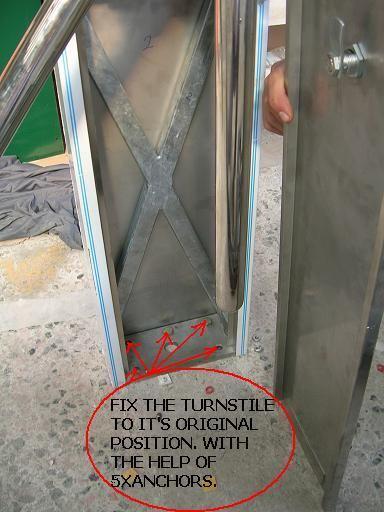
5 INSTALLATION (V 100 ) 1 Fix the mounting plate to it s orijinal position. With the help of 4xanchors 2. Put the turnstile on the mounting plate so that the holes are aligned. 3 Nut (4 pcs ) Washer (4 pcs ) Tighten the bolts provided to fix the cabinet to mounting frame. Steel Anchors M10 (4 pcs ) Not to scale. 4
6 OPENING TOP LID (V 100 WALL-MOUNT TYPE) 1 Turn the lock clockwise with the triangle key provided. 2 Raise the front part of the lid at the lock side, approximately 1-2 cm. 3 Push the lid forwards. Not to scale. 5
7 2 130 cm 122 cm Nut (4 pcs ) Washer (4 pcs ) 110 cm 32 cm 27 cm Nut (4 pcs ) Washer (4 pcs ) 70 cm MARK THE FLOOR AND FIX THE MOUNTING PLATES 150 cm 32 cm 33 cm 4 cm 33 cm 32 cm 97 cm 6
8 INSTALLATION (V 200 ) 1 Place the turnstile to the installation site. Mark the floor following the periphery of the legs (Fig 1). Take the turnstile aside. Mark the floor through the holes on the mounting frame which stand approximately 2 mm away from the inner lines (Fig 2 ). Fix the steel anchors and then the mounting frames using the washers and nuts. Put the turnstile back to its original position. Fix the turnstile to the mounting frames with the help of four stainless bolts provided. 2 Nut (4 pcs ) Washer (4 pcs ) 2 mm Line Steel Anchors M10 (4 pcs ) 3 M10 Stainless Bolts (4 pcs ) Not to scale. 7
9 OPENING AND CLOSING OF SIDE LIDS (V 300 ) CLOSE CLOSE OPEN OPEN Use the triangle key provided to open and close. INSTALLATION (V 300 ) Nut (4 pcs ) Washer (4 pcs ) Place the turnstile to the installation site. Open the side lids. Mark the floor through the holes on the mounting frame. Take the turnstile aside and fix the steel anchors. Put the turnstile back to its original position. After putting washers on the mounting frame through the studs, tighten the nuts. Steel Anchors M10 (4 pcs ) 8
10 INSTALLATION (V 400 / V 500 ) 1 Nut (4 pcs ) Washer (4 pcs ) Steel Anchors M10 (4 pcs) Place the mounting frame to the installation site. Mark the floor through the holes on the mounting frame. Take the mounting frame aside and fix the steel anchors to the floor. Place the mounting frame back to its original position. After putting washers on the mounting frame through the studs, tighten the nuts. Put the turnstile on the mounting frame. Make sure the turnstile is in the right position.fix the turnstile to the mounting frame by the help of four stainless bolts provided. 2 M10 Stainless Bolts (4 pcs) Nut ( 4 pcs ) Washer( 4 pcs ) M10 Stainless Bolts (4 pcs) Steel Anchors M10 (4 pcs) Not to scale. 9
11 INSTALLATION (C 100 ) 1 CLOSE OPEN CLOSE OPEN OPEN THE FRONT LID Place the turnstile to the installation site. Open the front lids. Mark the floor from the sides of the turnstile cabinet. Take the turnstile aside and fix the mounting plate to the floor by steel anchors. Put the turnstile back to its original position. Tighten the bolts provided to fix the cabinet to the mounting plate. 10
12 INSTALLATION (V 100 WALL-MOUNT TYPE ) 1 2 Place the turnstile to the installation site.open the top lid as described in page 5. Mark the wall through the holes on the mounting frame. Take the turnstile aside and fix the steel anchors. Put the turnstile back to its original position.after putting washers on the mounting frame through the studs, tighten the nuts. Not to scale. 11
13 3 Nut (4 pcs ) Nut (4 pcs ) Washer (4 pcs ) W asher (4 pcs ) PLACE THE TURNSTILE CABINETS ON THE MOUNTING PLATES, AND TIGHTEN THE BOLTS 12
")
14 INSTALLATION (E 100 ) Installation-1 Installation-2 13
15 INSTALLATION OF TRIPOD ASSEMBLY ( V 100-E100 / V 200 / V 300 / V 400 / V 500 ) Washer Nut Tripod assembly can be placed to the stud of the mechanism in four positions. But only one position is correct (one arm stands horizontal, two arms stand vertical). Turnstile will not perform if tripod assembly is mounted to the stud in one of the two wrong positions. After making sure the tripod assembly is in the right position, place the washer as in the figure and tighten the nut. Not to scale. 14
16 INSTALLATION (M 100 ) CLOSE OPEN Place the turnstile to the installation site.open the front lid by turning the lock counterclockwise with the triangle key provided. Mark the floor through the holes on the mounting frame. Take the turnstile aside and fix the steel anchors to the floor.place the turnstile back to its original position. After putting washer on the mounting frame through the studs, tighten the nuts. Not to scale. 15
17 1 Fix the mounting plate to it's orijinal position. With the help of 4xanchors. 2 Put the turnstile on the mounting plate so that the hales see each other. 3 Nut (4 pcs ) Washer (4 pcs ) Tighten the bolts provided to fix the cabiret to mounting frame. Steel Anchors M10 (4 pcs ) Not to scale. 16
18 INSTALLATION ( F 100 ) M12X6 STEEL ANCHORS TO FIX THE TURNSTILE TO CONCRETE BASEMENT Place the turnstile to the installation site. Mark the floor through the holes on the mounting frame. Take the turnstile aside and fix the steel anchors to the floor. Place the turnstile back to its original position. After putting washers on the mounting frame through the studs, tighten the nuts. 17
19 INSTALLATION ( F 100 ) WITH BASE PLATE Place the turnstile to the installation site. First, unscrew the bolts on the base plate of the turnstile. Pull up anti-slip rubber pad. Then mark the floor through the holes on the base plate. Take the turnstile aside and fix the steel anchors to the floor. Place the turnstile back to its original position. Tighten the countersunk bolts provided. Glue the base plate and put the anti-slip rubber pad on the base plate. Put the stainless steel strips to their original position. Screw the bolts on the stainless steel strips. Not to scale 18
20 INSTALLATION ( F 100 ) FULL HEIGHT TURNSTILES WITH CAGE TYPE CONSTRUCTION BASE PLATE AND CARLE INLET DETAILS Data and power cable inlet 40X80 Box Beam 40X80 Box Beam Data and power cable inlet 19
21 INSTALLATION (HH 100 ) Nut (8 pcs ) Washer (8 pcs ) Steel Anchors M10 (8 pcs ) (Note: Rotor and arms removed for clarity) Not to scale. Place the turnstile in the installation site. Mark the floor through the holes on the mounting frame. Take the turnstile aside and fix the steel anchors. Put the turnstile back to its original position. After putting washers on the mounting frame through the studs, tighten the nuts. 20
22 INSTALLATION (SWG 200 ) Locate the Swing Gate in desired position in accordance with the given instructions and architectural drawings. Mark flange hole locations. Remove gate and drill holes. Fix the steel anchors. Place gate properly over anchors. Tighten the nuts. Do same processes for other post. Perform all wiring in accordance with the given instructions. Check the post position and make necessary adjustments. Electro-magnetic lock works with 24 V DC.Therefore power cable (2x0.75 mm)should be laid through the hole under the square post up untill the electro-magnetic lock. 21
23 ADJUSTMENTS IN THE MECHANISM TRIPOD TURNSTILES 1. Drive Spring and Drive Spring Assembly Adjustment: CAM TRIPOD TURNSTILES MECHANISM INSTALLATION TOP VİEW DRIVE SPRING ASSEMBLY Optyma Engineering Co. Ltd. Picture 1.1 The correct adjustment of the drive spring assembly and the drive spring provides smooth and accurate operation of the tripod arms. Please follow the steps explained below to achieve this: 22
24 1. Loosen to screws between the drive spring assembly and the base plate. CAM 2. Adjust the turnstile s arm perpendicular to turnstile s body. TURNSTILE'S ARM SCREW TURNSTILE'S BODY DRIVE SPRING DRIVE SPRING ASSEBLY NUT Picture 1.2 Picture Tighten the drive spring (it is advised to tighten up to the end ). This operation is made with nut which is at the back part of the drive spring assembly. DRIVE ASSEMBLY SHAFT Picture 1.4 ROLLER CAM 4. Adjust the drive spring assembly so that drive spring shaft roller s outer surface will touch to the cam s concave face. Make a press further, up to 1-2 mm after this point. Picture Tighten the screws between the drive spring assembly and the base plate. 23
25 2. Shock Absorber Adjustment: CAM SHOCK ABSORBER TRIPOD TURNSTILES MECHANISM INSTALLATION TOP VİEW Optyma Engineering Co. Ltd. Picture 2.1 Shock absorber provides the silent and vibrationless operation of the turnstile. Kinetic energy of the tripod arm is absorbed by the shock absorber while arm comes to its original place. Shock absorber is shown at Picture 2.1. Shock absorber must be at the same axis with the cam s top point as shown in Picture 2.1. Also loosen the screws between the shock absorber assembly and the base plate. Then adjust the assembly to a suitable position moving the assembly forwards and backwards. For suitable adjusment: 1. Firstly, shock absorber must be at the same axis with cam s top point. 2. Then, rotate the cam to slightly left or right to release the shock absorber shaft roller forwards. Shock absorber shaft s roller must follow the cam for approximately 20mm from cam s top point, before it comes to its full stroke. If the shock absorber is standing too forwards (if the roller follows the cam surface much more than 20 mm), then the turnstile s arm will not rotate. However, if it is only a little bit more than 20 mm, then the arm will come to its original position more slowly. Exactly the opposite way, if the shock absorber is too backwards from the place it should be, then it doesn t contact the cam s surface and it doesn t perform its task. However, if the shock absorber shaft roller s contact distance to cam surface is only a little under 20 mm, then the tripod arm will more quickly come to its original position and passages will be faster. 3. Tighten the screws between the shock absorber assembly and the base plate. 24
26 MOVE WAY CAM ROTATE WAY SHOCK ABSORBER ASSEMBLY SHOCK ABSORBER Picture
27 3. Solenoid Adjustment: LOCK UP ARM CAM SOLENOID ASSEMBLY SOLENOID Optyma Engineering Co. Ltd. Picture 3.1 Solenoids lock up the turnstile s tripod arm at the mechanism. Solenoid lock up arm should be in the position as is seen in Picture 3.1. If the solenoid assembly adjustment is not made properly, then either the turnstile will not stay locked or will freely rotate. Therefore, please follow the steps described below, for the wright adjustment of the solenoid assembly: 1. Loosen the screws between the solenoid assembly and the base plate. 2. Move the solenoid assembly left or right untill the assembly is at the right place (see Picture 3.1. ) If the turnstile is fail-secure, then the turnstile will stay in locked position while it stands stil. And it will let the arm turn when energised. Try to rotate to test, tripod arms should not rotate in this position. Press into the solenoid s shaft with your finger as if it is energised. At this position, the tripod arm should rotate without touching the cam. All the adjustments are same for fail-safe turnstiles as well. The only difference being the operation is exactly the other way around. 3. Tighten the screws between of the solenoid assembly and the base plate. 26
28 MOVE WAY LOCK UP ARM SOLENOID ASSEMBLY SOLENOID MOVE WAY Picutre
29 SWG 200 HOW TO CHANGE THE SWING GATE OPENING DIRECTION Swing Gate is produced either opening right or opening left in standard. It depends on clients requirements. But if, for any reason, it is wanted to change the opening direction of the swing gate, this can be achieved very easily with SWG 200 Swing Gate s mechanism. Please, follow the steps described below for the wright adjustment of the swing gate opening direction: 1- Loosen the bolt between of the swing gate foot and the top lid. 2- Take the top lid up only for 1-2 cm. There is a spring under the top lid which is attached to it. Spring and lid mustn t disconnect.therefore be carefull not to pull the top lid more than 1-2cm. 28

30 3- There are two holes on the side of the top lid. Top lid is bolted to gate s foot from these holes. Gate opening direction adjustment is provided with these two holes.either of these holes must be at the same axis with gate foot s hole. Therefore, if the gate is wanted to open left, lid and gate s arm must be turned clock wise together until top lid s hole and gate foot s hole are at the same axis. 4- If the gate is wanted to open right, lid and gate s arm must be turned counter clock wise together until top lid s hole and gate foot s hole are at the same axis. 5- Tighten the bolt between the swing gate foot and the top lid. 29

31 ELECTRICAL COMPONENTS OF TURNSTILES 1. Electrical Components of V100-E100/V200/V300/V400/V500 1 Power Supply AC/DC Converter. This device changes the voltage to 24 VDC in order to 2 Main Fuse Foer the whole system. 3 Telemechanique Zelio PLC supply power to some of the components in the system. 24 VDC, Password prodected, programmable soft operated PLC card user interface. 8 inputs and 4 outputs are used. 4 Terminal Connects electric (energy) connection of the whole system. A- 220 VAC B- Open Direction C- Sensor Input D- Led Matrix E- Cycle Completed F- Receiver Input G- Counter 30

32 2.Electrical Components of F100 1 Telemechanique Zelio PLC 24 VDC, Password prodected, programmable soft operated PLC card user interface. 8 inputs and 4 outputs are used. 2 Power Supply AC/DC Converter. This device changes the voltage to 24 VDC in order to supply power to some of the components in the system. 3 Main Fuse For the whole system. 4 Relay Group PLC Protection Relay 5 Terminal Connects electric (energy) connection of the whole system. A- 220 VAC B- Open Direction C- Sensor Input D- Led Matrix E- Cycle Completed F- Receiver Input G- Counter 31

33 2.Electrical Components of M100 1 Contactor Drives the Motor Telemechanique Zelio PLC Excess Current Control Fuse Automatic Opening/Closing Button 24 VDC, Password prodected, programmable soft operated PLC card user interface. 8 inputs and 4 outputs are used. If There is excess current on the machine, system is stopped to prevent of force to the machine with the help of this fuse If you push the button once, Red Lamp lights and so Automatic Opening / Closing is functioning, If you push the button once again, Red Lamp does not light so Automatic Opening / Closing is not functioning. 5 Terminal Connects electric (energy) connection of the whole system. A- 220 VAC B- Power Supply Input C- Motor Output D- Brake Output E- Limit Switch F- Button Input 3
34 220 VAC INPUT 220 VAC INPUT 220 VAC OUTPUT 220 VAC INPUT POWER SUPPLY Optima Engineering Co. Ltd. POWER SUPPLY INPUT MOTOR OUTPUT BRAKE OUTPUT +24VDC GND RIGHT LIMIT CENTER LIMIT LEFT LIMIT GND +24VDC MOTOR OUTPUT BRAKE OUTPUT LIMIT SWITCH M 100 ELECTRICAL CONNECTIONS BUTTON INPUT COMMON OPEN DIRECTION 1. OPEN DIRECTION 2. 33
35 220 VAC INPUT 220 VAC INPUT 1 2 OPEN DIRECTION 2 1 COMMON OPEN DIRECTION 1 OPEN DIRECTION 2 +24VDC GND LED MATRIX DIRECTION 1 LED MATRIX DIRECTION 2 SOLENOID 1 GND SOLENOID 2 CYCLE COMPLETED COMMON CYCLE COMPLETED NO COUNTER DIRECTION 1 COUNTER DIRECTION 1 7SENSOR INPUT SENSOR INPUT LED MATRIX SOLENOID OUTPUT CYCLE COMPLETED COUNTER
36 DECLARATION OF CONFORMITY FOR MACHINES (DIRECTIVE 98 / 37 EEC, ATTACHMENT II, PART B) Manufacturer: OPTİMA MÜHENDİSLİK LİMİTED ŞİRKETİ KERESTECİLER SANAYİ SİTESİ 3. CADDE NO:8 SARAY KAZAN / ANKARA/ TÜRKİYE Declares that the products, V 100, V 200, V 300, V 400, V 500 Series Tripod Turnstiles M 100 Series Motorized Turnstiles F 100 Series Full-Height Turnstiles HH100 Series Half-Height Turnstiles SWG200 Series Swing Gate Turnstiles are constructed to be incorporated in a machine or to be assembled with other machinery to construct a machine considered modified by the directive 98 / 37 EEC are in confirmity with the regulations of the following EEC directives. Directive 98 / 37 EEC directive for machines Directive 73 / 23 EEC and directive 93 / 68 EEC low voltage Directive 89 / 336 EEC and directive 92 / 31 EEC and directive 93 / 68 EEC electromagnetic compatibility. And also are in confirmity with the following national standards. - TS EN / January 1996 Standard - TS EN / January 1996 Standard - TS EN 563 / April 1997 Standard - TS EN 418 / November 1995 Standard - TS EN / December 1995 Standard - TS EN / April 1995 Standard - TS EN / February 1998 Standard - TS EN / April 1997 Standard 4 April 2001 Ankara TURKEY İsmail Tamer ÜLGEN President Mechanical Engineer, B. Sc. 35
37 3

38 3
INSTRUCTIONS FOR INSTALLATION
 HYDRAULIC OPERATOR MODO 110-110/L FOR SINGLE- OR DOUBLE-WING SWING GATES INSTRUCTIONS FOR INSTALLATION GENERAL WARNINGS These warnings constitute an integral and essential part of the product and must
INDEX. 2.1 Construction and Foundation Control Cabinet Electrical and Electronics Components Hydraulic Units...
 ISO 9001: 2008 EN ISO 14001: 2004 SECURITY SYSTEMS Road Blockers INSTALLATION INSTRUCTIONS SURFACE TYPE HYDRAULIC RISING ROAD BLOCKER INDEX Page 1. GENERAL INFORMATION....3 2. SYSTEM COMPONENTS....5 2.1
PW320/PW330 USER MANUAL SWING GATE OPENERS 24V DC GEAR MOTOR FOR RESIDENTIAL. Flashing Light. Push Button. Control box. Gate 2.
 PW320/PW330 USER MANUAL SWING GATE OPENERS 24V DC GEAR MOTOR FOR RESIDENTIAL Flashing Light Push Button Control box Gate 2 Gate 1 Declaration of Conformity Applicant: Powertech Electronics Inc. Manufacturer:
PW150/PW200 USER MANUAL SWING GATE OPENERS 24V DC GEAR MOTOR
 PW150/PW200 USER MANUAL SWING GATE OPENERS 24V DC GEAR MOTOR FOR RESIDENTIAL Flashing Light Push Button Control box Declaration of Conformity Applicant: Powertech Electronics Inc. Manufacturer: Timotion
INDEX 1. GENERAL INFORMATION SYSTEM COMPONENTS Construction Control Cabinet... 6
 ISO 9001: 2008 EN ISO 14001: 2004 SECURITY SYSTEMS Bollards INSTALLATION INSTRUCTIONS PNEUMATIC RISING BOLLARDS INDEX Page 1. GENERAL INFORMATION... 3 2. SYSTEM COMPONENTS... 4 2.1 Construction... 4 2.2
SWING GATE OPENERS 24V DC GEAR MOTOR
 SWING GATE OPENERS 24V DC GEAR MOTOR FOR RESIDENTIAL USER MANUAL Flashing Light Push Button Control box Gate 2 Gate 1 Index 1. Warnings 2 4. Technical Characteristics 16 2. Product Description 2.1 Applications
IRREVERSIBLE OPERATOR FOR SWING GATES AND DOORS
 VH IRREVERSIBLE OPERATOR FOR SWING GATES AND DOORS WARNING!! Before installing, thoroughly read this manual that is an integral part of the pack Our products if installed by qualified personnel capable
Automatic concealed bollards 275 H600 and 275 H800 with pit
 Automatic concealed bollards 275 H600 and 275 H800 with pit Technical installation manual CE Declaration of conformity Warnings for the installer Bollard technical data Preparing and installing the bollard
EC MACHINE DIRECTIVE COMPLIANCE DECLARATION
 EC MACHINE DIRECTIVE COMPLIANCE DECLARATION (DIRECTIVE 89/392 EEC, APPENDIX II, PART B) Manufacturer: FAAC S.p.A. Address: Via Benini, 1 40069 - Zola Predosa BOLOGNA - ITALY Hereby declares that: the 770
Typical Installation Schematic
 The 760 Gate Automation System The FAAC 760 automation system consists of a monoblock hydraulic unit and foundation box assembly. The system is designed for underground installation, and will not alter
EC MACHINE DIRECTIVE COMPLIANCE DECLARATION
 770 EC MACHINE DIRECTIVE COMPLIANCE DECLARATION (DIRECTIVE 89/392 EEC, APPENDIX II, PART B) Manufacturer: FAAC S.p.A. Address: Via Benini, 1 40069 - Zola Predosa BOLOGNA - ITALY Hereby declares that: the
UNDERGROUND OPERATOR FOR SWINGING GATES. WARNING!! Before installing, thoroughly read this manual that is an integral part of the pack
 UNDERGROUND OPERATOR FOR SWINGING GATES COMPAS 2 WARNING!! Before installing, thoroughly read this manual that is an integral part of the pack Our products if installed by qualified personnel capable to
Automation Swing Gate Opener
 Automation Swing Gate Opener Operating and installation instructions SP EIFFEL 400 V1.0 Rev 08/01 CONTENTS 0) GENERAL SAFETY REGULATIONS...Page 0 1) DESCRIPTION...Page 03 ) TECHNICAL SPECIFICATIONS 3)
Model 2300DL Installation Guide
 Model 2300DL Installation Guide POWER ACCESS CORPORATION 4 HERSHEY DRIVE, DOCK 4 ANSONIA, CT 06401 800-344-0088 WEBSITE: www.power-access.com EMAIL: salesinfo@power-access.com 1 STANDARD PARTS MODEL 2300DL
Model 2300JL Installation Guide
 Model 2300JL Installation Guide POWER ACCESS CORPORATION 4 HERSHEY DRIVE, DOCK 4 ANSONIA, CT 06401 800-344-0088 WEBSITE: www.power-access.com EMAIL: salesinfo@power-access.com 1 STANDARD PARTS MODEL 2300JL
6 x 10 Belt Disc Sander
 6 x 10 Belt Disc Sander FOR HELP OR ADVISE ON THIS PRODUCT PLEASE CALL OUR CUSTOMER SERVICE HELP LINE : 01509 500400 THE MANUFACTURER RESERVES THE RIGHT TO ALTER THE DESIGN OR SPECIFICATION TO THIS PRODUCT
Operating Instructions Type MPT 53
 Operating Instructions www.turnstiles.us Type MPT 53 Contents 1. Delivery... 2 2. Safety...3-4 3 Description and operation... 5 4. Technical Data 6 5. oundation...6-9 6. Assembly and installation...10-13
SKC400U SLIDING GATE OPENER OWNER S MANUAL
 SKC400U SLIDING GATE OPENER OWNER S MANUAL IMPORTANT SAFTEY INFORMATION Installing the SKC400U Gate Opener requires wiring of standard 110V electrical lines. This should only be performed by a trained
DOCUMENT TYPE = FITTING INSTRUCTIONS ORIGINAL LANGUAGE = ENGLISH. Maximum door weight = 40kg per leaf total system 80kg
 Evolve SIM Kit DOCUMENT TYPE = FITTING INSTRUCTIONS ORIGINAL LANGUAGE = ENGLISH 80kg Maximum door weight = 40kg per leaf total system 80kg Maximum door width 2 x 2mtr Track = 675-1058mm (Up to 2035 mm
Operating Instructions Pedestrian Turnstile Type MPT 33
 Operating Instructions Pedestrian Turnstile Type MPT 33 Contents 1. Delivery...2 2. Safety...2 3 Description and operation...3 4. Foundation...4-5 5. Assembly and installation...6-9 6. Electrical connection...10-11
FORCE SPD 800/1500/2000
 English AUTOMATION SYSTEMS FOR SLIDING GATES Operating and installation instructions FORCE SPD 800/1500/2000 v1.0 Rev 11/2012 INDEX 1) General Safety Regulations... pág. 01 2) Description... pág. 02 3)
These operating instructions apply for: NCX 380 NCZ 300 NCX 480 NCZ 370 NCX 580 L NCZ 480 NCX 660 K NCZ 560 NCZ 660 NCZ 800
 Original instructions Operating Instructions for May 2010 Electric Internal Vibrators BA No. 1092E Series NCX and NCZ These operating instructions apply for: NCX 380 NCZ 300 NCX 480 NCZ 370 NCX 580 L NCZ
Table of Contents. General Safety Preparation for Installation Parts List Optional Accessories Part List... 5
 REV 12a Table of Contents General Safety....... 2 Preparation for Installation....... 3 Parts List....... 4 Optional Accessories Part List...... 5 Technical Specifications & Feature...... 5 Installation
BR230 MOTORIZED VIP. OPERATION and MAINTENANCE MANUAL
 BR230 MOTORIZED VIP OPERATION and MAINTENANCE MANUAL 1 TABLE OF CONTENTS TURNSTILE SAFETY INSTRUCTIONS 3 TURNSTILE USER INSTRUCTIONS 3 BR230 MOTORIZED VIP TURNSTILE TECHNICAL SPECIFICATIONS 4 BR230 MOTORIZED
VECTRIX VX-2 SERVICE MANUAL. Version 1.0/May 2011 VECTRIX, LLC
 www.vectrix.com CONTENTS SECTION A: Tools 1 Tools Needed SECTION B: Mechanical Parts 1 Front Fairing 2 Front Console Cover 3 Speedometer Cover 4 Front Vertical Panel Cover-Lower 5 Front Vertical Panel
COYOTE ENTERPRISES, INC. 9/10 BLAST WHEEL MAINTENANCE & ASSEMBLY MANUAL
 COYOTE ENTERPRISES, INC. 9/10 BLAST WHEEL MAINTENANCE & ASSEMBLY MANUAL Parts & Machinery for the Abrasive Blast Industry 27301 East 121st Street Coweta, Oklahoma 74429 (918) 486-8411 Fax (918) 486-8412
DKC400Y AC Sliding Gate Installation Manual. Sliding Gate Opener. Model: DKC400Y. Installation Manual WARNING
 Sliding Gate Opener Model: DKC400Y Installation Manual WARNING Read and thoroughly understand all instructions before installing or operating this automatic gate opener. Failure to do so may cause serious
MEKO OPENER FOR RACK-DRIVEN SLIDING MOTOR
 Installation Manual MEKO OPENER FOR RACK-DRIVEN SLIDING MOTOR 02_2016 1. WARNINGS AND GENERAL SAFETY INSTUCTIONS This manual contains important safety information. An incorrect installation or an improper
Automatic concealed bollards 275 H600 and 275 H800 Control station
 Automatic concealed bollards 275 H600 and 275 H800 Control station Technical installation manual CE Declaration Warnings for the installer Bollard electrical connection Technical specifications for control
AUTOMATIC CONTROL ROLLING DOOR OPENER
 AUTOMATIC CONTROL ROLLING DOOR OPENER INSTALLATION INSTRUCTION AUTOMATIC OBSTRUCT PHOTOELECTRIC BEAM ROLLING CODE SYSTEM AUTO CLOSE DOOR ANTI-THEFT SYSTEM INSTALLATION INSTRUCTION AND RDO OWNERS MANUAL
INDEX 1. GENERAL INFORMATION SYSTEM COMPONENTS OPERATION INSTRUCTIONS MAINTENANCE... 14
 ISO 9001: 2008 EN ISO 14001: 2004 SECURITY SYSTEMS Bollards INSTALLATION INSTRUCTIONS HYDRAULIC RISING BOLLARDS INDEX 1. GENERAL INFORMATION... 2 Page 2. SYSTEM COMPONENTS... 3 2.1 Construction... 3 2.2
Contents. EC DECLARATION OF CONFORMITY FOR MACHINES... p. 10. WARNINGS FOR THE INSTALLER... p. 10
 Contents EC DECLARATION OF CONFORMITY FOR MACHINES... p. 10 WARNINGS FOR THE INSTALLER... p. 10 1. DESCRIPTION AND TECHNICAL SPECIFICATIONS... p. 11 1.1. DIMENSIONS... p. 11 2. ELECTRIC DEVICES (standard
Rolling Door Operator User s Manual
 Rolling Door Operator User s Manual MODEL: RSI-500KG Rolling Steel Ind. Brooklyn NY Tel. 718 272-4444 OUTLINE 1. Important safety information 1 2. Main technical parameters 1 3. Introduction 1 4. Installation
GENERAL SAFETY... 3 PARTS LIST...
 Rev 17a 1 GENERAL SAFETY... 3 PARTS LIST... 4 GTR100... 4 GTR058... 5 TECHNICAL SPECIFICATIONS... 6 FEATURES:... 6 QUICK INSTALLATION GUIDE... 7 GATE ARM INSTALLATION... 8 BEFORE YOU START... 8 INSTALLATION
Installation manual. English. mystrike OPENER FOR RACK-DRIVEN SLIDING MOTOR
 Installation manual English mystrike OPENER FOR RACK-DRIVEN SLIDING MOTOR 1. WARNINGS AND GENERAL SAFETY INSTRUCTIONS This manual contains important safety information. An incorrect installation or an
WEL. Manuale di installazione e manutenzione per automazioni per porte battenti. Installation and maintenance. for swing doors.
 WEL IP1891 - rev. 2007-04-20 I GB F D E P Manuale di installazione e manutenzione per automazioni per porte battenti. Installation and maintenance manual for automations for swing doors. Manuel d installation
SLIDING DOOR OPERATOR INSTRUCTION MANUAL
 SLIDING DOOR OPERATOR INSTRUCTION MANUAL (MODEL NO. 1071.101 & 1071.102) Please carefully keep this manual for good maintenance. Caution Be sure the door opener is far away from moisture, vibration, and
Porte 150 Users Manual Swing Gate Opener 24V DC
 Porte 150 Users Manual Swing Gate Opener 24V DC for residential use only Signal Light Push-button Control Box 14 Contents 1. Important Safety Information 2. Product Description and Application 2.1 Application
Sliding Gate Operator User's Manual
 Sliding Gate Operator User's Manual SL600AC. Products introduction Please read the instructions carefully before proceeding. MCU is supplied to control the gate operator. Keypad / single button interface.
Installation Manual. Swing Gate System. Leading the way...
 Installation Manual 402 Swing Gate System Leading the way... Contents EC DECLARATION OF CONFORMITY FOR MACHINES... p. 2 WARNINGS FOR THE INSTALLER... p. 2 1. DESCRIPTION AND TECHNICAL SPECIFICATIONS...
Hunter Automatics HA-8. Installation Manual
 Hunter Automatics HA-8 Installation Manual WARNING TO REDUCE RISK OF INJURY 1. READ AND FOLLOW ALL INSTALLATION INSTRUCTIONS CAREFULLY. FAILURE TO DO SO MAY RESULT IN PERSONAL INJURY OR PROPERTY DAMAGE
Jabiru J170/230/430/250/450 Constructors Manual. Pre-Paint>Fuselage>Undercarriage>Assemble main gear
 Objectives of this task: In this task you will assemble the main undercarriage legs, which includes fitting the axles, disc brakes and wheels and adjusting the brakes. Materials required: Cards # J8 Dual
FITTING AND CONNECTION INSTRUCTIONS
 LEPUS is an oil-bathed motor-reducer created for sliding gates automation. The motor-reducer irreversibility allows a perfect and safe gate closing avoiding the setup of an electrolock and in case of power
Owner s Manual. For SOLAR BOOM GATE. Model: CA-5000 SOLAR
 ECA Electronic Engineering Pty. LTD. Australia Tel: 03-95720 535 Fax: 95 720 536 Owner s Manual For SOLAR BOOM GATE Model: CA-5000 SOLAR ( 2009 / Version 1 ) 1 1 Introduction 1.0 Control PCB Wiring INSTALLATION
EC DECLARATION OF CONFORMITY
 EC DECLARATION OF CONFORMITY Manufacturer : Address: Declares that: FAAC S.p.A. Via Benini, 1-40069 Zola Predosa BOLOGNA - ITALY 844 T control board, conforms to the essential safety requirements of the
ALVARADO (1029 mm) 25 (635 mm) 36.5 (927.1 mm)
 25 (635 mm) 36.5 (927.1 mm)") ALVARADO EDCX Bullnose Waist High Turnstile Technical Specifications Dimensions Unit Height: Unit Width: Unit Depth: 40.5 (1029 mm) 25 (635 mm) 36.5 (927.1 mm) Materials Cabinet: Formed and welded 14 gauge
ALVARADO EDCX Bullnose Waist High Turnstile Technical Specifications Dimensions Unit Height: Unit Width: Unit Depth: 40.5 (1029 mm) 25 (635 mm) 36.5 (927.1 mm) Materials Cabinet: Formed and welded 14 gauge
PCS 100 SYSTEM INSTALLATION INSTRUCTIONS
 PCS 00 SYSTEM INSTALLATION INSTRUCTIONS PCS - 00 + - POWER 4VDC CW TIME LO NL 4 5 6 ON C&K SDA06 CCW HI RL WHITE BROWN BLACK NC L NC L ON C&K SDA04 4 NO M NO M RESET START 5V 4V COM (0) BLUE SCU-00 Made
SARGON S - M - L. All rights reserved INSTALLATION MANUAL
 INSTALLATION MANUAL Our compliments for your excellent choice. SARGON LINE S (300mm) M (400mm) and L (600mm) electro-mechanical gear motor has been produced for reliability and high quality. This Manual
Sliding Gate Operator User's Manual
 Sliding Gate Operator User's Manual PY800AC/PY00AC. Products introduction Please read the instructions carefully before proceeding. MCU is supplied to control the gate operator. Keypad / single button
JOINT INSTALLATION MANUALS AND SAFETY INFORMATION
 INSTALLATION MANUALS AND SAFETY INFORMATION SEA S.p.A. Zona industriale 64020 S.ATTO Teramo - (ITALY) Tel. +39 0861 588341 r.a. Fax +39 0861 588344 www.seateam.com seacom@seateam.com REV.00-06/2016 1 TABLE
YG101 SWING GATE OPENER OWNER S MANUAL
 YG101 SWING GATE OPENER OWNER S MANUAL IMPORTANT SAFTEY INFORMATION Installing the YG101 Gate Opener requires wiring of standard 110V electrical lines. This should only be performed by a trained technician.
EC DECLARATION OF CONFORMITY FOR MACHINES (DIRECTIVE 98/37/EC) WARNINGS FOR THE INSTALLER
 WARNINGS FOR THE INSTALLER") EC DECLARATION OF CONFORMITY FOR MACHINES (DIRECTIVE 98/37/EC) Manufacturer: Address: Declares that: FAAC S.p.A. Via Benini, 1-40069 Zola Predosa BOLOGNA - ITALY 740-24V mod. operator is built to be integrated
EC DECLARATION OF CONFORMITY FOR MACHINES (DIRECTIVE 98/37/EC) Manufacturer: Address: Declares that: FAAC S.p.A. Via Benini, 1-40069 Zola Predosa BOLOGNA - ITALY 740-24V mod. operator is built to be integrated
SKF Electro-pneumatic Barrel Pump EPB-Pump-ECO (Original operating and maintenance instructions according to EU Directive 2006/42/EC)
") SKF Electro-pneumatic Barrel Pump EPB-Pump-ECO (Original operating and maintenance instructions according to EU Directive 2006/42/EC) TABLE OF CONTENTS 1 EC Declaration of incorporation...1 2 General description...2
SKF Electro-pneumatic Barrel Pump EPB-Pump-ECO (Original operating and maintenance instructions according to EU Directive 2006/42/EC) TABLE OF CONTENTS 1 EC Declaration of incorporation...1 2 General description...2
DIGITAL BATTERY TORQUE WRENCH (BC-RAD SELECT) USER GUIDE
 USER GUIDE") DIGITAL BATTERY TORQUE WRENCH (BC-RAD SELECT) USER GUIDE W.CHRISTIE (INDUSTRIAL) LTD CHRISTIE HOUSE, MEADOWBANK ROAD, ROTHERHAM, SOUTH YORKSHIRE, S61 2NF, UK T: +44(0)1709 550088 F: +44(0)1709 550030 E:
DIGITAL BATTERY TORQUE WRENCH (BC-RAD SELECT) USER GUIDE W.CHRISTIE (INDUSTRIAL) LTD CHRISTIE HOUSE, MEADOWBANK ROAD, ROTHERHAM, SOUTH YORKSHIRE, S61 2NF, UK T: +44(0)1709 550088 F: +44(0)1709 550030 E:
PNEUMATIC PUMP Series
 PNEUMATIC PUMP Series 3103... User and Maintenance Manual Original text translation TABLE OF CONTENTS 1. INTRODUCTION 2. GENERAL DESCRIPTION 3. PRODUCT-MACHINE IDENTIFICATION 4. TECHNICAL CHARACTERISTICS
V200 USER MANUAL SWING GATE OPENER. 100kg 1.5m. 100kg 1.5m
 V200 USER MANUAL SWING GATE OPENER 100kg 1.m 100kg 1.m Content Important Safety Advice... Content of the Kit... Connection Diagram... Installation Guide... Actuator... Control box... AC cable wiring...
AUTOMATIC BOLLARD ASSEMBLY AND OPERATING MANUAL
 AUTOMATIC BOLLARD ASSEMBLY AND OPERATING MANUAL MPIE10 400/600/800 Please read the manual very carefully before installation V 2.1 R 03/2018 A) Warning to the user and/or installer 1) CAUTION: It is important
Z TECHNICAL INSTRUCTIONS
 ÍNDICE: Z40 2.0 TECHNICAL INSTRUCTIONS 1.- Error list 2.- Replace the control board 3.- Opening the machine 4.- Replace the power board 5.- Dismantling motor and gear box 6.- Assembly of gear box 7.- Pushing
GATES-ELECTRIC AND MECHANICAL SELF CLOSING 2000 SERIES
 2014 GATES-ELECTRIC AND MECHANICAL SELF CLOSING TURNSTILE SECURITY SYSTEMS Inc. THIS CATALOGUE IS MEANT AS REFERENCE MATERIAL FOR TURNSTILE SECURITY SYSTEMS Inc. FOR THE SOLE PURPOSE OF INFORMING POTENTIAL
MKey9-series Safety Interlock Switch with Guard Locking
 Original instructions MKey9-series Safety Interlock Switch with Guard Locking ABB AB / Jokab Safety Varlabergsvägen 11, SE-434 39 Kungsbacka, Sweden www.abb.com/jokabsafety Read and understand this document
Installation, operation and maintenance manual
 Installation, operation and maintenance manual HCT1LX30 FULL RISE SCISSOR LIFT READ THIS ENTIRE MANUAL BEFORE INSTALLATION TO ENSURE CORRECT OPERATION AND A LONG SERVICE LIFE 2 Tiraines str. Riga, LV 1058
SlimStile EV. Tripod Turnstile for Internal or External Installation (*)
") Tripod Turnstile for Internal or External Installation (*) Tripod Turnstiles are compact and cost-effective entrance solutions designed for smooth and silent operation, less wear and tear and reduced power
Tripod Turnstile for Internal or External Installation (*) Tripod Turnstiles are compact and cost-effective entrance solutions designed for smooth and silent operation, less wear and tear and reduced power
Requirements LEO Power Operator Installation Instructions Patents: 5,881,497; 7,316,096; 7,484,333 CAUTION CAUTION WARNING
 CAUTION 80-957-00-00 (08-0) Series 570 Door Openings 85 to 0 or to 80 Adjustable Arm and Slide Track Application Maximum Hinge Side Frame Reveal to /8 (mm) Hinge (Pull) Side of Door Installation 5700 LEO
Mobile Access, TimeTec Smart Tripod Turnstile TTS 2200B Installation Manual
 www.timeteccloud.com Mobile Access, TimeTec Smart Tripod Turnstile TTS 2200B Installation Manual TS2200: Tripod Turnstile TS2211: Tripod Turnstile with Controller and RFID Reader TS2222: Tripod Turnstile
User manual. e-gate SLD-24V
 User manual FOR e-gate SLD-24V 24V Sliding Gate Operators Contents how to use your automatic gate operator...... 1 how the controls work.................. 2 how to manually release the gate...........
Hydraulics. Part B, Section 1. This section covers the following unit configurations. 3700V
 Part B, Section 1 Model Voltage Pump Manifold Control This section covers the following unit configurations. 3500V 3700V 3860 3890 3930 3960 All Piston (D) 4-Port (A) 6-Port (B or C) 2-Port (S or T) Vista
Quick Start. Flat head screwdriver. Wheel carriage x 2. M8 Nut x 2. Strap Bolt x 2. 1 x 2m Anodised Track
 Evolve 80 Glass FITTING INSTRUCTIONS - NOTICE DE POSE - MONTAGE HANDLEIDING - MONTAGEANLEITUNG ISTRUZIONI DI MONTAGGIO - INSTUCCIONES DE MONTAJE 80kg Maximum Weight = 80kg - Maximum Door Width = 1100mm
TECHNICAL DATA HYDRAULIC UNIT
 GB INSTRUCTIONS MANUAL RISING BOLLARD OIL-HYDRAULIC AUTOMATION COMPONENTS strabuc 918 RELEASE KEY PLUG FOR RELEASE HOLE BOLLARD COVER 12 V WARNING LIGHTS REFLECTORS COMPLETELY RETRACTABLE POST WITH ELECTROPHORESIS
Maximum Weight = 80 kg for 2 doors; Maximum door width = 1100mm (to suit up to maximum 2120mm clear opening) Quick Start. 5 & 4mm Allen keys.
 Quick Start. 5 & 4mm Allen keys.") EVOLVE 80 SIM KIT FITTING INSTRUCTIONS - NOTICE DE POSE - MONTAGE HANDLEIDING - MONTAGEANLEITUNG ISTRUZIONI DI MONTAGGIO - INSTUCCIONES DE MONTAJE 80kg Maximum Weight = 80 kg for 2 doors; Maximum door
EVOLVE 80 SIM KIT FITTING INSTRUCTIONS - NOTICE DE POSE - MONTAGE HANDLEIDING - MONTAGEANLEITUNG ISTRUZIONI DI MONTAGGIO - INSTUCCIONES DE MONTAJE 80kg Maximum Weight = 80 kg for 2 doors; Maximum door
HIGH SPEED SLIDING GATE OPENER
 HIGH SPEED SLIDING GATE OPENER Model: is1200 + Elsema s Eclipse Control Card with GDS Operator USER MANUAL CONTENTS Section No: Page No: 1 Safety Precautions 3 2 Wiring Requirements 4 3 Installation details
QJY245DS~DA. Two Post Lift Installation & Adjustment Manual
 QJY245DS~DA Two Post Lift Installation & Adjustment Manual Table of Contents 1. Warning 2 2. Summary 2 3. Use 2 4. Mainly technology parameter 2 5. Basic structure of the production 3 6. Safety device
E Series Enclosures Installation Instructions (UL /UL2416 E Series Equipment Cabinet/Rack)
") E Series Enclosures Installation Instructions (UL60950-1/UL2416 E Series Equipment Cabinet/Rack) WeRackYourWorld.com 1-866-TRY-GLCC (879-4522) Instructions for the following Great Lakes Enclosures: GL720E-2432,
E Series Enclosures Installation Instructions (UL60950-1/UL2416 E Series Equipment Cabinet/Rack) WeRackYourWorld.com 1-866-TRY-GLCC (879-4522) Instructions for the following Great Lakes Enclosures: GL720E-2432,
Requirements LEO Power Operator Installation Instructions Patents: 5,881,497; 7,316,096; 7,484,333 CAUTION CAUTION WARNING
 CAUTION 80-957-00-00 (08-0) Series 570 Openings 85 to 0 or to 70 Double Lever Arm Application for Frame Reveals (76) to 7 (78mm)* Stop (Push) Side of Installation 5700 LEO Operator Installation Instructions
Mechanical Disc Brake
 (English) DM-BR0007-02 Dealer's Manual Mechanical Disc Brake BR-CX77 BR-CX75 BR-R517 BR-R515 BR-R317 BR-R315 BR-TX805 IMPORTANT NOTICE This dealer s manual is intended primarily for use by professional
Instruction Manual for the. E-SL 450 Series
 Instruction Manual for the E-SL 450 Series Estate Slide Summary of Functions The Estate Slide is only to be used for vehicular Slide gates in a Class I setting. Class I: A vehicular gate opener (or system)
Service Manual Gulf Stream Electronic Full Wall Slide Systems
 Service Manual Gulf Stream Electronic Full Wall Slide Systems CONTENTS Page Before you operate the slide system 2 Operating Instructions 3 Preventive maintenance 3 Manually overriding your slide system
70 Series 8700 End Mount Three Phase Brake Instructions IP56 (NEMA 4) Housing
 Housing") Bulletin No. BK4773-3 (08/2016) 70 Series 8700 End Mount Three Phase Brake Instructions IP56 (NEMA 4) Housing Read carefully before attempting to assemble, install, operate or maintain the product described.
Bulletin No. BK4773-3 (08/2016) 70 Series 8700 End Mount Three Phase Brake Instructions IP56 (NEMA 4) Housing Read carefully before attempting to assemble, install, operate or maintain the product described.
LABORATORY MICROMOTOR HP35 ON-OFF
 LABORATORY MICROMOTOR HP35 ON-OFF USER AND MAINTENANCE MANUAL 1. DESCRIPTION HP35 on-off is a powerful and reliable micromotor, expressly designed for daily use in the Dental, Gold and Jewellery fields.
USE AND MAINTENANCE MANUAL PRESS ARM HELP REV / 12
 USE AND MAINTENANCE MANUAL PRESS ARM HELP REV. 01 1 / 12 CONTENTS 1 INTRODUCTION 3 2 PRODUCT DESCRIPTION 4 3 GENERAL INFORMATION 5 4 INSTALLATION 6 5 USE 10 6 MAINTENANCE 12 REV. 01 2 / 12 CHAPTER 1 -
EC DECLARATION OF CONFORMITY FOR MACHINES (DIRECTIVE 98/37/EC)
") EC DECLARATION OF CONFORMITY FOR MACHINES (DIRECTIVE 98/37/EC) Manufacturer: Address: Declares that: FAAC S.p.A. Via Benini, 1-40069 Zola Predosa BOLOGNA - ITALY The operator mod. 844 R Reversible is built
EC DECLARATION OF CONFORMITY FOR MACHINES (DIRECTIVE 98/37/EC) Manufacturer: Address: Declares that: FAAC S.p.A. Via Benini, 1-40069 Zola Predosa BOLOGNA - ITALY The operator mod. 844 R Reversible is built
Installation manual ASTER AUTOMATION FOR SWING GATES 11_16
 Installation manual ASTER AUTOMATION FOR SWING GATES 11_16 Contents 1. GENERAL SAFETY PRECAUTIONS... page 01 2. INTENDED USE AND APPLICATION... page 01 2.1 Kit contents... page 01 2.2 Technical features...
BAYT 980. Oil-hydraulic OIL-HYDRAULIC BARRIER FOR TRAFFIC CONTROL INSTALLATION MANUAL. code 4425 Post with fixing base. POLO 44 - optional -
 Oleodinamica BAYT 980 Oil-hydraulic OIL-HYDRAULIC BARRIER FOR TRAFFIC CONTROL POLO 44 - optional - BAYT 980 560 code 4425 Post with fixing base the gate opener Made in Italy INSTALLATION MANUAL GB INSTRUCTIONS
NYOTA 115. Electro-mechanical sliding gate operator. Instruction manual
 NYOTA 115 Electro-mechanical sliding gate operator Instruction manual GB INSTRUCTIONS FOR THE INSTALLATION OF THE AUTOMATION NYOTA 115 FOR A CORRECT INSTALLATION AND GOOD PERFORMANCE OF NYOTA 115 READ
Safe & Secure Series Electric Actuator with Internal Battery Back-up Installation, Operation & Maintenance Manual
 Safe & Secure Series Electric Actuator with Internal Battery Back-up Installation, Operation & Maintenance Manual For Use with: SNS4, SNS6, SNS10 & SNS15 Models Additional supplements may be needed for
Read this entire manual before operation begins.
 Read this entire manual before operation begins. Record below the following information which is located on the serial number data plate. Serial No. Model No. Date of Installation Contents Specifications.............
MOUNTING AND CONNECTING INSTRUCTIONS 1. GATE ARRANGEMENT ENGLISH
 SATURN SATURN is a motor reducer designed for the automation of sliding gates with grease lubrication of the gear in the 600 version; in oil bath in the 1000 and 2000 versions. The irreversibility of the
(1032 mm) 30.5 (775 mm) 44 ( mm)
 30.5 (775 mm) 44 ( mm)") ALVARADO EDCX-EK Waist High Turnstile Technical Specifications Dimensions Unit Height: Unit Width: Unit Depth: 40.625 (1032 mm) 30.5 (775 mm) 44 (1117.6 mm) Materials Cabinet: Formed and welded 14 gauge
ALVARADO EDCX-EK Waist High Turnstile Technical Specifications Dimensions Unit Height: Unit Width: Unit Depth: 40.625 (1032 mm) 30.5 (775 mm) 44 (1117.6 mm) Materials Cabinet: Formed and welded 14 gauge
INSTALLATION MANUAL ENGLISH ALPHA 200 ALPHA 330. L C (stroke) 960 mm 1160 mm
 960 mm 1160 mm") INSTLLTION MNUL The LPH is provided with a mechanical locking system that grants the operator locking in the opened and closed position avoiding any needs for electric locks and/or magnetic locks. The
INSTLLTION MNUL The LPH is provided with a mechanical locking system that grants the operator locking in the opened and closed position avoiding any needs for electric locks and/or magnetic locks. The
L /2012 rev 0 BISON 45 OTI UNIONE NAZIONALE COSTRUTTORI AUTOMATISMI PER CANCELLI, PORTE SERRANDE ED AFFINI
 L8542965 03/2012 rev 0 BISON 45 OTI UNIONE NAZIONALE COSTRUTTORI AUTOMATISMI PER CANCELLI, PORTE SERRANDE ED AFFINI 1 470 327 F A 500 825 B 243.5 2 C 445 210 15 ±5 205 92 50 2 3 4 I D2 D2 D1 5 T 6 D A
Ignition Timing - Honda 180-Degree Twins
 Ignition Timing - Honda 180-Degree Twins First thing to do is make a quick test light - I used a 12 volt indicator bulb from a speedo. Test leads with alligator clips make hookup easy... The point plate
RotaSec FOS. Manual Full-Height Turnstile for External Installation. Passage in both directions is electronically controlled.
 Manual Full-Height Turnstile for External Installation RotaSec FOS is a robust, trouble-free full-height turnstile. Constructed as a mono-block and self-supporting, the unit is easily installed. FOS AT91
Automatic Swing door Operator SD3108 Product manual. Notes: please keep the manual properly for reference. Do carefully read this manual before use.
 Automatic Swing door Operator SD3108 Product manual Notes: please keep the manual properly for reference. Do carefully read this manual before use. Safety Warning! Please read carefully the instructions
AU DU PONT DE LUTTRE BRUSSELS BELGIUM PHONE: FAX: OPERATING MANUAL. Electric Fully Automatic Floor Saw FS 1218 EX
 AU DU PONT DE LUTTRE 74-1190 BRUSSELS BELGIUM PHONE: 322 34 83 162 FAX: 322 34 83 136 OPERATING MANUAL Electric Fully Automatic Floor Saw FS 1218 EX 2 Important information before you start! When the machine
INSTALLATION MANUAL (cod )
") is a bollard designed for the management of traffic areas, parkings and protection of public and private accesses. It has an hydraulic system is engineered in our factory to achieve minimum noise and maximum
is a bollard designed for the management of traffic areas, parkings and protection of public and private accesses. It has an hydraulic system is engineered in our factory to achieve minimum noise and maximum
CE DECLARATION OF MACHINE CONFORMITY
 CE DECLARATION OF MACHINE CONFORMITY (DIRECTIVE 2006/42/EC) Manufacturer : Address: Declares that: FAAC S.p.A. Via Calari, 10-40069 Zola Predosa BOLOGNA - ITALY Operator mod. 541 3ph is built to be incorporated
TUB DOORS SHOWER DOORS
 D INSTALLATION INSTRUCTIONS TUB DOORS: SHOWER DOORS: LBTDD6062 LBSDD4879 LBSDD6079 Version 5.0 PREPARATION FOR INSTALLATION PREPARATION FOR INSTALLATION READ ALL INSTRUCTIONS BEFORE UNPACKING THE PRODUCT
L /2012 rev 0 BISON 30 OTI UNIONE NAZIONALE COSTRUTTORI AUTOMATISMI PER CANCELLI, PORTE SERRANDE ED AFFINI
 L8542968 07/2012 rev 0 BISON 30 OTI UNIONE NAZIONALE COSTRUTTORI AUTOMATISMI PER CANCELLI, PORTE SERRANDE ED AFFINI 1 458 250 A F 645 477 B 195 470 270 2 C 13 ±5 156 70 2 3 4 D2 R D2 I D1 T 5 W D H G R
Read this entire manual before operation begins.
 Read this entire manual before operation begins. Record below the following information which is located on the serial number data plate. Serial No. Model No. Date of Installation Contents Specifications.............
LABORATORY MICROMOTOR HP45 MULTIFUNCTION
 LABORATORY MICROMOTOR HP45 MULTIFUNCTION USER AND MAINTENANCE MANUAL 1. DESCRIPTION HP45 Multifunction is a powerful and reliable micromotor, expressly designed for daily use in the Dental, Gold and Jewellery
CK-5000T Metropolis Patterson Transmission Crankset Installation Instructions Published Jul, ZSP001.v3 Full Speed Ahead
 CK-5000T Metropolis Patterson Transmission Crankset Installation Instructions Published Jul, 2011. ZSP001.v3 Full Speed Ahead Introduction Congratulations on your Full Speed Ahead product. Please read