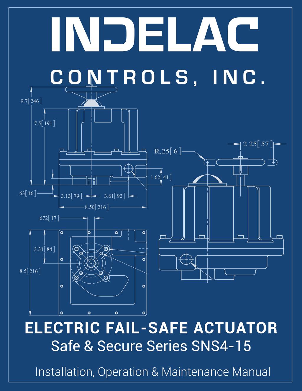
Safe & Secure Series Electric Actuator with Internal Battery Back-up Installation, Operation & Maintenance Manual
|
|
|
- Donald Jennings
- 5 years ago
- Views:
Transcription
1

2 Safe & Secure Series Electric Actuator with Internal Battery Back-up Installation, Operation & Maintenance Manual For Use with: SNS4, SNS6, SNS10 & SNS15 Models Additional supplements may be needed for selected optional equipment including, but not limited to models with: modulating controls, timers, speed controllers & remote/off/local controls. REVISED: JULY 2016 TELEPHONE: TOLL FREE: FAX: SHIPPING ADDRESS: 6810 POWERLINE DR.-FLORENCE, KY For a digital copy of this manual, access to training videos, access to 3D product renderings, or to request additional support VISIT OUR WEBSITE AT
3 INTRODUCTION: Thank you for selecting Indelac Controls, Inc. (ICI) for your valve or damper automation requirement. We at ICI are proud of our products and feel confident they will meet or exceed your expectations of quality and reliability. Every precaution has been taken to insure that your equipment will arrive undamaged; however, accidents do occur. Therefore, the first thing you must do upon receipt of your package is to inspect it for damage. If the box is damaged there is a possibility that the equipment inside the box may be damaged as well. If this is the case YOU MUST FILE A CLAIM with the delivering CARRIER. All shipments are F.O.B. our factory and it is YOUR RESPONSIBILITY to file a claim for damages. STORAGE: If the actuators are scheduled for installation at a later date: 1. Store off the floor. 2. Store in a climate controlled building. 3. Store in a clean and dry area. FOR FUTURE REFERENCE RECORD: 1. Actuator model number 2. Actuator enclosure type NEMA 4, NEMA 4X, NEMA 7, NEMA 4 & 7 3. Actuator output torque LB-IN 4. Motor characteristics, Voltage Hertz Phase 5. Actuator serial number 6. Date of installation Put into operation 7. Valve Data: 7a. Manufacturer 7b. Style & fig. No. 7c. Size 7d. End connection 7e. Material of construction, Body Stem & ball 7f. Brake away torque PSI 7g. Other helpful data MEDIA: 1. System media 2. Temperature, (deg. F.) Maximum,. Minimum,. 3. Pressure PSI *As this information is listed it is important to pay attention to all of the actuator specifications relative to the valve specifications and system requirements. If the actuator is not properly sized for the valve and application the life will be shortened or it may not work at all. Page 2
4 TOOLS REQUIRED: *ADDITIONAL TOOLS WILL BE REQUIRED FOR THE SCREWS TO MOUNT THE VALVE TO THE ACTUATOR. SNS4 15 SERIES Cover Screws 7/16 Socket. Terminal Strip Screws 3/16 Wide Flat Head Screwdriver. Cam Set Screw 5/64 Allen Wrench. Mounting Pad Screws ½ Socket. SUGGESTED MAXIMUM TORQUE VALUES FOR FASTENERS (IN-LBS.) SCREW SIZE LOW CARBON STEEL 18-8 SS 316 SS ALUMINUM ¼ / / ½ / Page 3
5 PRODUCT DESCRIPTION: The SNS4-15 Safe & Secure Series Actuator is a quarter turn Open/Close Actuator with Battery Backup Power ALL IN ONE! No more mounting a separate Fail Safe Unit to provide power in case of external power failure. The actuator s internal battery will provide power to the motor in the event of an external power failure. The actuator can be configured in the field for FAIL OPEN, FAIL CLOSE or Continue to run upon power failure (run time is dependent on size of actuator and torque load see additional data below). This new series of actuator can operate loads from 400 in/lbs. to 1500 in/lbs. These actuators can be ordered to operate on input voltages of 115vac, 230vac, 24vac, 24vdc or 12vdc and are enclosed in a standard M series NEMA 7 housing. Switching from external power to battery power is seamless when the external power source fails, the internal transfer circuit switches to battery power automatically without any operator intervention. Depending on the fail setting that the operator made for the actuator, the valve will go to that position. Once the external power is restored, the actuator will automatically switch back to external power and the battery will be re-charged! The actuator will then return to its last position before the power had failed. This unit is available as a Standard OPEN/CLOSE Actuator or with the Modulating Option for precise valve position control using 4-20mA, 0-10V or 1-5V external input signal. UNIT SPECIFICATIONS: Enclosure rating: Motor Duty Cycle: Locked Rotor Current: Full Load Amps: Weight: Mounting Pad: Operating Voltages: NEMA 4 Standard; 4X, 7 & 4/7 also available 100% Standard 4.2 Amps 1.8 Amps 18 Lbs. ISO 5211 F07 115vac, 230vac, 24vac, 24vdc, 12vdc Incoming Power Fuse: TR5 Pico Fuse, 250V / 115vac & 230vac = 500mA; 24vac = 3.15A Motor Fuse: Power: Position Indication: Battery: Battery Recharge Time: Battery Life on Trickle Charge: Auxiliary Switch Rating: Feedback Indicator Lamps: Input Signal Contact Rating: 6A PTC Automatic Resettable 30 Watts Max. / add 20 Watts for optional heater Dome Style Visual Indicator and wired for Light Indication 12vdc, 0.8AHr Approximately 8 Hours 4-5 years Dry Contact, vac 100mA max. 3A Page 4


6 MECHANICAL MOUNTING: The Safe & Secure Actuator can be direct mounted to any valve using the standard ISO 5211 F07 Output. Optional Inserts are available for ISO 5211 F03 and ISO 5211 F04. See the drawing below for the actuator output mounting dimensions for valves requiring mounting hardware. Actuator Bottom View Reference Image: Actuator mounted to sample ball valve. Page 5

7 CUSTOMER ELECTRICAL CONNECTIONS FOR STANDARD OPEN/CLOSE: All customer electrical connections are done per the below wiring diagrams. Incoming power should be wired using 18awg minimum. Control signal wiring may be 22awg or larger for direction control and indicator lamps. All wiring is to be completed through the conduit opening using the appropriate conduit Refer to your local electrical codes. Remove the actuator cover by loosening the cover screws and pulling straight up on the cover to complete the wiring and set-up. WARNING! Pay close attention to the Wiring Diagrams when connecting the input power to the actuator. Improper power connection can result in damage to the actuator or serious injury to the installer. DC CONNECTION WIRING DIAGRAM Page 6

8 AC CONNECTION WIRING DIAGRAM J6, Customer Connections Pin 1 towards bottom J5, Power Input Connections Pin 1 towards bottom Customer Connections, Board Connector View NOTE: Make sure the connectors are fully seated after making all wiring connections. Page 7
9 CUSTOMER ELECTRICAL CONNECTIONS FOR MODULATING OPTION: AC CONNECTION WITH 4-20mA CONTROL WIRING DIAGRAM Page 8
10 DC CONNECTION WITH 4-20mA CONTROL WIRING DIAGRAM Page 9
 On the circuit board, move the Fail Switch to the desired FAIL position.")

11 ACTUATOR SET-UP FOR STANDARD OPEN/CLOSE ACTUATOR: After the actuator is mounted mechanically to the valve and the external electrical wiring is complete, the actuator is ready for set up. The actuator cover will need to be removed, if not already done so. 1) On the circuit board, move the Fail Switch to the desired FAIL position. The description of the 3 positions are as follows: RUN = ACTUATOR WILL CONTINUE TO RUN WITH USER COMMAND SIGNAL WHEN POWER FAILS UNTIL THE BATTERY DIES. OPEN = ACTUATOR WILL MOVE TO THE OPEN POSITION WHEN POWER FAILS. CLOSE = ACTUATOR WILL MOVE TO THE CLOSE POSITION WHEN POWER FAILS. Fail Switch Slide to the desired position RUN OPEN CLOSE ** DO NOT switch the FAIL switch while the actuator is moving Turn OFF power before moving switch! 2) Plug the battery connector into the circuit board at position J1. NOTE: If the Fail Switch was moved to the CLOSE position, the actuator will begin to move to the Close location. Limit Switch CAMs (Bottom = Close; Top = Open) Loosen the set screw to rotate for adjustment. J1, Battery Connector Plug the battery into the J1 Connector on the board Status LEDs 3) Apply external power to the actuator. 4) Using the external direction control signal, run the actuator open and closed to verify that the valve is opening and closing fully. If not, the Open and Close CAMs may be adjusted to allow more or less motion in both directions. The CAM set screw needs to be loosened to rotate the CAM. Re-tighten the set screw when the desired valve position is achieved. ** If control signal is provided by a PLC, program needs to incorporate a delay between the OPEN & CLOSE signal. Page 10
 The Safe & Secure board will supply power to the Modulating Controller Board.")
 Set the DIP Switch #3 to ON (up) & #4 to OFF (down) on the DMC")
 & #4 is set to ON (up).")

12 ACTUATOR SET-UP FOR MODULATING OPTION ACTUATOR: After the actuator is mounted mechanically to the valve and the external electrical wiring is complete, the actuator is ready for set up. The actuator cover will need to be removed, if not already done so. 1) The Safe & Secure board will supply power to the Modulating Controller Board. When the incoming power fails, the battery will supply power to run the motor to the selected FAIL position. Safe and Secure Board Fail Dip Switches DC Modulating Controller Span Pot Zero Pot Green & Red LEDs close and open indicators 2) Set the DIP Switch #3 to ON (up) & #4 to OFF (down) on the DMC 102 Controller Board. This will run the actuator to the CLOSED position in the event of a loss of input control signal. If it is desired to have the actuator go to the OPEN position when the input signal is lost, then DIP Switch #3 is set to OFF (down) & #4 is set to ON (up). NOTE: If the incoming power should fail, the battery will supply the Controller board and the actuator will operate normally as long as the input signal is present. The actuator will operate until the battery loses power. If the input signal should fail along with the incoming power, the Controller Board will drive the actuator to the selected FAIL Position on battery power and remain until power & signal are restored. 3) Plug the battery connector into the circuit board at position J1. J1, Battery Connector Plug the battery into the J1 Connector on the board Status LEDs 4) Apply external power to the actuator. Page 11
13 5) Apply the input signal (4-20mA, 0-10v, etc.) to run the actuator open and closed to verify that the valve is opening and closing fully. If not, the ZERO and SPAN pots on the Controller Board may be adjusted to allow more or less motion in both directions. OPERATION: Upon applying external supply power to the actuator, the Blue LED on the Safe & Secure Board should illuminate indicating that the power from the external source is on. See picture above for LED location. When the external power fails, the Blue LED will turn off and the Green LED will illuminate indicating that the actuator is now running on battery power. When this occurs, the actuator will move to the desired position (RUN, OPEN or CLOSED), as selected by the operator during set-up. For example, if the actuator is moving towards the Open position with the Fail Switch set for CLOSED, the actuator will STOP, and move to the Closed position if the external power should fail. On the Modulating version, the actuator will continue to operate from the input signal, as long as it is present. Only when the input control signal fails, will the actuator move to the CLOSED or other set position. If the Safe and Secure Board Green LED should turn off and the Red LED turn on, this indicates that the battery power is low. The battery either needs to be charged or replaced. There is a battery charge circuit built into the Safe & Secure actuator that will charge the battery when the external power is on. If after 8 hours of on board charging, the Red LED remains on, then the battery needs to be replaced. If the battery is too low, the actuator will FAIL in place. With the external power on, switch the direction control contact or change the input control signal from Open to Close to verify that the actuator/valve Opens and Closes. If Open and Close indicator Lamps have been installed, the Open Lamp will come on when the valve gets to the fully Open position. The Close Lamp will come on when the valve gets to the fully closed position. If the Optional Heater and Thermostat have been installed, the Heater will operate when the external power supply is on. If the external power supply should fail and the actuator runs on battery power, the Heater will NOT be operational. TESTING AND TROUBLESHOOTING: Battery Condition Test 1) Remove the external power and verify that the Green LED illuminates. If it does, then the battery is properly charged and ready for operation. 2) If the Red LED illuminates, the battery is low. 3) Apply external power to the actuator and verify that the Blue LED illuminates. 4) Wait 8 hours and repeat by removing the external power. 5) If the Green LED illuminates, the battery is good and is charged. 6) If the Red LED illuminates, or is OFF, the battery is bad and needs to be replaced. Power Test **DO NOT CHANGE ANY SWITCH SETTINGS WITH THE POWER ON** 1) Apply external power to the actuator. The Blue LED should illuminate. 2) If there is no Blue LED, check that the incoming power is terminated & the breaker is on. 3) Next, verify that the power is correctly connected to the actuator and the wires are tight in the input connector. 4) On AC versions, make sure that the 115/230V switch is in the proper position for the appropriate power input. 5) On the DC versions, verify that either the 24V or 12V is connected to the appropriate terminal. 6) If still no Blue LED, check the on board fuse (AC & modulating versions only) in the Safe & Secure Actuator. 7) If the fuse is blown, replace the fuse. Page 12
14 8) If the fuse is good, the circuit board is bad and needs to be replaced. 9) On modulating versions, a control input signal needs to be present to run the actuator. DUTY CYCLE: All SNS Series actuators are rated 100% duty cycle at 100% ambient temperature at rated torque. THERMAL OVER LOAD: The Safe and Secure series actuator motors are internally fused with a resettable fuse. When the motor current rises to an overload level, the on-board fuse will trip until the motor cools down. The fuse will automatically reset and allow the actuator to resume operation. It is the responsibility of the operator to check the entire system and clear any jams or valve binding prior to restarting the system. MECHANICAL OVER LOAD: ICI actuators are all designed to withstand stall conditions. It is not recommended to subject the unit to repeated stall conditions; however, should it occur the actuator would not experience gear damage. ORDERING PARTS: When ordering parts please specify: Actuator Model Number, Actuator Serial Number, Part Number & Part Description. RECOMMENDED SPARE PARTS: Set of limit switches, spare battery, spare fuses for specified input voltage. NEMA 7 ENCLOSURE, GENERAL: In general, operation and maintenance of a NEMA 7 electric actuator is no different than that of a NEMA 4 electric actuator. However, there are some precautions that must be followed. 1. DO NOT install in ambient temperatures that exceed 140 degrees F. 2. DO NOT under any circumstances remove the actuator cover while in a hazardous location when the contacts are still live, this could cause ignition of hazardous atmospheres. 3. DO NOT under any circumstances use a NEMA 7 electric actuator in a hazardous location that does not meet the specifications for which the actuator was designed. The actuator is clearly tagged with the NEMA classification it was designed for. 4. Mount, test and calibrate actuator on valve in non-hazardous location. 5. When removing the cover care must be taken not to scratch, scar or deform the flame path of the cover or base of the actuator, this will negate the NEMA 7 rating of the enclosure. 6. When replacing the cover on actuators rated NEMA 4 and 7 take care that the gasket is in place to assure the proper clearance after the cover is secured. After securing the cover screws check the clearance between the cover and the base, a.002 thick by 1/2 wide feeler gauge may not enter between the two mating faces more than All electrical connections must be to state and local codes and in accordance with the specifications for which the unit is being used. *After proper installation the actuator will require little or no maintenance. In the event maintenance is required remove it from the hazardous location before attempting to work on it. If the actuator is in a critical application and down time is not permitted it is advisable to have a spare actuator in stock. Page 13

15 Page 14
16 Frequently Asked Questions SYMPTOM PROBLEM SOLUTION ACTUATOR DOES NOT RESPOND TO CONTROL SIGNAL. Power not on Turn on power Actuator wired wrong Check wiring diagram & rewire Wrong voltage Check power supply & make appropriate changes Thermal overload activated Allow motor to cool, actuator will automatically reset Actuator and valve in opposite Remove actuator and rotate 90 positions when actuator was mounted. degrees & remount Fuse Blown Input signal wires not tight in terminals Replace with proper value fuse Tighten terminal block screws Bad Brake ACTUATOR WILL NOT OPEN OR CLOSE COMPLETELY. Travel limits set wrong Reset cams. Remove brake hub & try to run Valve torque too high for actuator Mechanical stops not removed Install correct size actuator Remove stops, CAUTION: Do not remove any part required for proper operation VALVE OSCILLATES. Valve torque too high for actuator Actuator without brake installed on butterfly valve Motor brake out of adjustment. Set screw loose in brake disc Install correct size actuator. Install brake Adjust brake Adjust brake and tighten setscrew MOTOR RUNS BUT OUTPUT SHAFT DOES NOT ROTATE. Gear damage or sheared pin Contact ICI or nearest distributor Page 15

17 Contact Information Debbie Voges ext. 100 Matt Robinson ext. 109 Talbot Caywood ext. 110 For News & Updates, Check Out Our Blog: Page 16
Electric Actuator Installation, Operation & Maintenance Manual
 Electric Actuator Installation, Operation & Maintenance Manual For Use with: All Standard AC Voltage Models Additional supplements may be needed for selected optional equipment including, but not limited
12 Series Linear Electric Actuator Installation, Operation & Maintenance Manual
 12 Series Linear Electric Actuator Installation, Operation & Maintenance Manual TELEPHONE: +1-859-727-7890 TOLL FREE: +1-800-662-9424 FAX: +1-859-727-4070 E-MAIL: DVOGES@INDELAC.COM MROBINSON@INDELAC.COM
SAFE & SECURE ACTUATOR PRODUCT MANUAL
 INDELAC CONTROLS SAFE & SECURE ACTUATOR PRODUCT MANUAL Product Description: The Safe & Secure Series Actuator is a quarter turn Open/Close Actuator with Battery Backup Power ALL IN ONE! No more mounting
Electric Modulating Actuator Installation, Operation & Maintenance Manual
 Electric Modulating Actuator Installation, Operation & Maintenance Manual For Use with: All Modulating AC Voltage Models Additional supplements may be needed for selected optional equipment including,
Electric Actuator Installation, Operation & Maintenance Manual
 ICI Indelac Controls, Inc. Electric Actuator Installation, Operation & Maintenance Manual 6810 Powerline dr.-florence, Ky. 41042 - Telephone 859-727-7890, Tool free 800-662-9424 Fax. 859-727-4070, e-mail:
12 Series Linear Actuators. Operation & Maintenance Manual, Analog Positioner Installation
 12 Series Linear Actuators Operation & Maintenance Manual, Analog Positioner Installation 6810 POWERLINE DR.-FLORENCE, KY. 41042 - TELEPHONE 859-727-7890, TOLL FREE 1-800-662-9424 FAX. 859-727-4070, E-MAIL:
Milwaukee's Electric Actuator Installation, Operation & Maintenance Manual
 Milwaukee's Electric Actuator Installation, Operation & Maintenance Manual 1 Cover screws 9/64 Allen wrench. Terminal strip screws 1/8 wide flat head screw driver. Mounting pad screws 3/8 socket Cover
ICI Indelac Controls, Inc. Installation, Operation & Maintenance Manual For Electric Spring Return Actuator
 ICI Indelac Controls, Inc. Installation, Operation & Maintenance Manual For Electric Spring Return Actuator 6810 Powerline Dr. Florence, Ky. 41042 Telephone 859-727-7890, Tool free 800-662-9424, Fax. 859-727-7-4070,
DMC mA Positioner
 DMC-100 4-20mA Positioner TELEPHONE: +1-859-727-7890 TOLL FREE: +1-800-662-9424 FAX: +1-859-727-4070 E-MAIL: DVOGES@INDELAC.COM MROBINSON@INDELAC.COM TCAYWOOD@INDELAC.COM SHIPPING ADDRESS: 6810 POWERLINE
LLN Series Linear Actuator Installation, Operation & Maintenance Manual
 ICI Indelac Controls, Inc. N Series inear Actuator Installation, Operation & Maintenance Manual 6810 Powerline Dr.-Florence, Ky. 41042 - Telephone 859-727-7890, Toll free 800-662-9424 Fax. 859-727-4070,
Quarter Master Series 94 Actuator
 Quarter Master Series 94 Actuator Installation, Operation and Maintenance Manual Assembly Series 94 Manual Rev V 9/5/13 Page 1 of 12 Table of Contents Series 94 Electric Actuator Introduction... 3 Description...
Installation, Operation and Maintenance Manual
 HQ 005. ELECTRIC ACTUATORS QUARTER-TURN ELECTRIC ACTUATORS Installation, Operation and Maintenance Manual s Version Ver. 1 Revision Rev. 1 Document No. HKQI-611 Small & Compact Design High corrosion resistance
Quarter Master Chief Series 92 Actuator
 Quarter Master Chief Series 92 Actuator Installation, Operation and Maintenance Manual File: Series 92 O & M manual Rev. V 4/22/2013 Page 1 of 13 Table of Contents Series 92 Electric Actuator Introduction...
Series 10 Actuator. Installation, Operation and Maintenance Manual
 Series 10 Actuator Installation, Operation and Maintenance Manual File: series10.man Location: assembly/manual Rev.E 6/24/14 Page 1 of 8 Table of Contents Series 10 Electric Actuator Introduction... 3
VA-908x Series Electric Rotary Actuators for Two-Position and Modulating Service
 VA-908x Series Electric Rotary Actuators for Two-Position and Modulating Service Installation Instructions VA-908x Code No. LIT-12011566 Issued August 24, 2009 Applications The VA-908x Series Electric
Control Panel with Valve Positioner (CPVP) Installation, Operation & Maintenance Manual
 Installation, Operation & Maintenance Manual") Control Panel with Valve Positioner (CPVP) Installation, Operation & Maintenance Manual TPHON: +1-859-727-7890 TO F: +1-800-662-9424 FAX: +1-859-727-4070 -MAI: VOGS@INAC.COM MOINSON@INAC.COM TCAYWOO@INAC.COM
Control Panel with Valve Positioner (CPVP) Installation, Operation & Maintenance Manual TPHON: +1-859-727-7890 TO F: +1-800-662-9424 FAX: +1-859-727-4070 -MAI: VOGS@INAC.COM MOINSON@INAC.COM TCAYWOO@INAC.COM
ECON ELECTRIC ACTUATOR Fig ELA60 Ex
 ECON ELECTRIC ACTUATOR Fig. 7907, type ELA60 Fig. 7907 ELA60 IP67 (optionally IP68) Fig. 7907 ELA60 Ex EX ǁ 2G Ex d IIB T4 Gb Small & Compact quarter turn actuator Mechanical position indicator High output
Series 70 24V On/Off Electric Actuator Operation and Maintenance Manual
 Series 70 Operation and Maintenance Manual TABLE OF CONTENTS 1. Definition of Terms............................................. 1 2. Safety................................................... 1 3. Storage..................................................
IMO-517 (7027) ISSUE 3/97 ERA12, 25, 50, 83, 125, 167, 208 AND 250 ELECTRIC ACTUATORS INSTALLATION, MAINTENANCE AND OPERATING INSTRUCTIONS
 ISSUE 3/97 ERA12, 25, 50, 83, 125, 167, 208 AND 250 ELECTRIC ACTUATORS INSTALLATION, MAINTENANCE AND OPERATING INSTRUCTIONS") ERA12, 25, 50, 83, 125, 167, IMO-517 (7027) ISSUE 3/97 208 AND 250 ELECTRIC ACTUATORS INSTALLATION, MAINTENANCE AND OPERATING INSTRUCTIONS 2 Table of Contents 1 GENERAL...........................................
ERA12, 25, 50, 83, 125, 167, IMO-517 (7027) ISSUE 3/97 208 AND 250 ELECTRIC ACTUATORS INSTALLATION, MAINTENANCE AND OPERATING INSTRUCTIONS 2 Table of Contents 1 GENERAL...........................................
HQ Series ¼ Turn Electric Actuator
 HQ Series ¼ Turn Electric Actuator Models HQ004 and HQ006 Operation and Installation Manual HQ Series Operation and Installation Manual REV B 27-02-2012 1 Table of Contents: General 1.0 Actuator Mounting
Surepowr Series 100 Installation Manual
 Surepowr Series 100 Installation Manual Safety First In the maintenance and operation of mechanical equipment, safety is the basic factor which must be considered at all times. Through the use of the proper
Your Global Flow Control Partner. Series 70 24V On/Off Electric Actuator Operation and Maintenance Manual
 Your Global Flow Control Partner Series 70 Table of Contents 1. Definition of Terms.......................................2 2. Safety............................................. 2 3. Storage............................................2
Valcom Failsafe Unit. 1620ESv2 SERIES. Operation and Maintenance Manual
 Valcom Failsafe Unit 1620ESv2 SERIES Operation and Maintenance Manual Table of Contents Section Title Page 1. - Introduction.. 2. - Unpacking the Failsafe unit. 3. - Installation 3.1 - Auto / Timed UPS
SUREPOWR TM SERIES -SURE 24/25 FIELD INSTALLATION INSTRUCTIONS
 SUREPOWR TM SERIES -SURE 4/5 FIELD INSTALLATION INSTRUCTIONS Safety First In the maintenance and operation of mechanical equipment, SAFETY is the basic factor which must be considered at all times. Through
Surepowr Series Sure 150
 RCS Acutators Surepowr Series Sure 50 Installation Manual Safety First In the maintenance and operation of mechanical equipment, safety is the basic factor which must be considered at all times. Through
Technical Specification. RCS Electric Actuators with a ProfiBus Field Control and Communication Module
 The following specification defines the minimum requirements for the supply of motor operated valve actuators with a field communication bus system for remote control. The complete system shall consist
HQ Series ¼ Turn Electric Actuator
 HQ Series ¼ Turn Electric Actuator Models HQ008 to HQ300 Operation and Installation Manual HQ Series Operation and Installation Manual 1 Table of Contents: General 1.0 Actuator Mounting 2.0 Power Requirements
SUREPOWR TM SERIES -SURE 49 FIELD INSTALLATION INSTRUCTIONS
 SUREPOWR TM SERIES -SURE 49 FIELD INSTALLATION INSTRUCTIONS Safety First In the maintenance and operation of mechanical equipment, SAFETY is the basic factor which must be considered at all times. Through
Electric Actuated Ball Valves 150 lb Flanged Stainless Steel, Full Port 1/2 to 4 inch Pipe Sizes
 Electric Actuated Ball Valves 150 lb Flanged Stainless Steel, Full Port 1/2 to 4 inch Pipe Sizes SERIES Features Direct mount Full Port 16 Stainless Steel ball valve 2-piece ANSI Class 150 flanged body
MD10. Engine Controller. Installation and User Manual for the MD10 Engine Controller. Full Version
 MD10 Engine Controller Installation and User Manual for the MD10 Engine Controller. Full Version File: MartinMD10rev1.4.doc May 16, 2002 2 READ MANUAL BEFORE INSTALLING UNIT Receipt of shipment and warranty
Electric Actuated Ball Valves 2-way Stainless Steel, Full Port 1/4 to 2 inch NPT
 Electric Actuated Ball Valves 2-way Stainless Steel, Full Port 1/4 to 2 inch NPT SERIES Features Full Port 16 Stainless Steel ball valve LED light gives continuous status indication IP67 weatherproof polyamide
Electric Actuated Ball Valves 2-way Stainless Steel, Full Port 1/4 to 2 inch NPT
 Electric Actuated Ball Valves 2-way Stainless Steel, Full Port 1/4 to 2 inch NPT SERIES Features Full Port 16 Stainless Steel ball valve LED light gives continuous status indication IP67 weatherproof polyamide
SERIES 73 ELECTRIC ACTUATOR OPERATION AND MAINTENANCE MANUAL. The High Performance Company
 SERIES 73 ELECTRIC ACTUATOR OPERATION AND MAINTENANCE MANUAL The High Performance Company Table Of Contents: page Safety instructions: Definitions of Terms... 2 Introduction principle of operation...
Electric Actuated Ball Valves 3-Piece Stainless Steel, Full Port 1/4 to 3 inch NPT
 Electric Actuated Ball Valves 3-Piece Stainless Steel, Full Port 1/4 to 3 inch NPT SERIES Features Direct mount Full Port 316 Stainless Steel ball valve 3-piece swing out body designed for easy maintenance
PEAKTRONICS DMC-101 ADDITIONAL FEATURES. DC Motor Controller, 5A DMC-101
 PEAKTRONICS The Peaktronics DC Motor Controller is used for proportional positioning of actuators that use either DC motors or DC solenoids. The wide operating range of the (10 to 30 VDC and loads up to
Electric Actuated Ball Valves 150# Flanged Stainless Steel, Full Port 1/2 to 4 inch Pipe
 1/2 to 4 inch Pipe Features Direct mount ISO5211 Full Port stainless steel ball valve 2-piece ANSI Class 150 flanged body 275 PSI working pressure at 100 F (38 C) Highly visual dome style valve position
HQ-006 ¼ Turn Actuator
 HQ-006 ¼ Turn Actuator Installation & Maintenance Manual HQ-006 I&M Manual HQ-402-0606 1 Table of Contents General 1.0 Actuator Mounting 2.0 External Construction 3.0 Standard Wiring Diagrams 4.0 Manual
Quarter Master Series 94 Actuator
 Quarter Master Series 94 Actuator Installation, Operation and Maintenance Manual Assembly Series 94 Manual Rev X 7/31/17 Page 1 of 13 Table of Contents Series 94 Electric Actuator Introduction... 3 Description...
Electric Actuated Ball Valves 3-piece Stainless Steel, Full Port 1/4 to 3 NPT
 1/4 to 3 NPT Features Direct mount ISO5211 Full Port stainless steel ball valve 3-piece swing out body designed for easy maintenance 1000 PSI working pressure at 100 F (38 C) Highly visual dome style valve
IOM A-0984E IP68-420DC AUTOMATED PILOT ACTUATOR Installation and Operation Manual
 IOM A-0984E IP68-420DC AUTOMATED PILOT ACTUATOR Installation and Operation Manual Please ensure to read and understand the contents of this manual. TABLE OF CONTENTS 1 HEALTH AND SAFETY: READ FIRST...3
RP-4000 Reserve Power Control
 Instruction Manual IM-0580 RP-4000 Reserve Power Control Table of Contents General Information... 2-3 Introduction... 2 Cautions... 2 Receiving/Inspection... 2 Storage... 2 Equipment Return... 2 Identification
Actuated Valves PRICING
 Electric & Pneumatic Actuated Valves Actuated Valves PRICING Page Suitable for Oil-Free air handling to 5 psi, not for distribution of compressed air or gas Spears Manufacturing Company Due to Material
Installation Instructions
 WE-500 Series Electric Actuator Installation Instructions Introduction The WE-500 Series electric actuator is a rotary valve actuator with outputs of 500 in-lbs. It has been designed for NEMA 4, 4X and
Installation and Operating Manual
 . Installation and Operating Manual WE/XE-690, 1350, 1700, 2640, 4400, 5200, 6900, 10500 17500, 25690 1 (Rev. 020113) IOM8011.docx . Table of Contents Introduction Page Safety Instructions..... 3 Introduction
DeZURIK DR 125 ROTARY DIAPHRAGM ACTUATOR
 DR 125 ROTARY DIAPHRAGM ACTUATOR Instruction D10507 January 2017 Instructions These instructions provide information about. They are for use by personnel who are responsible for installation, operation
Electric Actuators Maximum in-lbs
 Maximum 14040 in-lbs NEMA 4, 4X, 7 ER- Series Features ISO / DIN valve interface Mounting in any position Thermal overload protection (AC & DC except 12 VDC) Friction brake (standard for AC motors except
Model Combustible Gas Sample Draw Detector Head Operator s Manual
 Model 1017-06 Combustible Gas Sample Draw Detector Head Operator s Manual Part Number: 71-0356 Revision: P1 Released: 2/4/15 www.rkiinstruments.com WARNING Read and understand this instruction manual before
M-3025CB-AV Fuel Pump
 SAVE THESE INSTRUCTIONS M-3025CB-AV Fuel Pump Owner s Manual TABLE OF CONTENTS General Information... 2 Safety Instructions... 2 Installation... 3 Operation... 4 Maintenance... 4 Repair... 5 Troubleshooting...
Powers TM Controls EA 338 Electronic Actuator
 Powers TM Controls Technical Instructions Document No. 155-136P25 EA 338-1 Description Features 24 Vac power supply. The s are used with floor mount linkage kits to operate dampers in HVAC installations.
Electric Actuator Accessories. Timer Board 115 VAC Input Suffix A (For EVR, EVS & EVT actuators)
") Timer Board Suffix A Timer board installs within actuator enclosure. Board shown is for EVR, EVS, and EVT actuators. Cycle Time Rate Regulator Suffix B Cycle time rate regulator installs within actuator
Timer Board Suffix A Timer board installs within actuator enclosure. Board shown is for EVR, EVS, and EVT actuators. Cycle Time Rate Regulator Suffix B Cycle time rate regulator installs within actuator
Electric Actuated 3-Way Ball Valves T-Port, Stainless Steel, Full Port 1/4 to 2 inch NPT
 Electric Actuated 3-Way Ball Valves T-Port, Stainless Steel, Full Port 1/4 to 2 inch NPT SERIES Features Full Port 316SS diverter valve Polyamide IP67 weatherproof enclosure with UV protection Multi-voltage
E Series Electric Actuators
 ENGINEERING MANUAL 13560 Larwin Circle, Santa Fe Springs, CA 90670 Phone: (562) 802-2255 (800) 783-7836 Fax: (562) 802-3114 Netsite: www.svf.net E-mail: Sales@SVF.net E Series Electric Actuators 1/4 3
SPECIFICATIONS ATTENTION OPERATION DESCRIPTION
 EMP-5 Installation Manual - P/N 80103 - Ed. 01/09 EMP-5 Current or Voltage Input Drive Modulating Actuator Installation Instructions 1 7 SPECIFICATIONS The EMP-5 series actuators provide damper control
NOAH ACTUATOR NA-SERIES MANUAL EMICO EUNHA MACHINERY INDUSTRIAL CO.,LTD.
 NOAH ACTUATOR NA-SERIES MANUAL EMICO EUNHA MACHINERY INDUSTRIAL CO.,LTD N A Table of Contents 1. Caution 2 2. Storage 4 3. Actuator Specification 5 4. Standard Specification 7 5. Optional Specification
1.0 Features and Description
 1.0 Features and Description The is an intelligent actuator designed for precise control of quarter turn valves and dampers. Using stepper motor technology, the SmartStep proportionally positions valves
INSTALLATION TURN SIGNAL MIRRORS 1432
 1432 PARTS INCLUDED 1 Left Side Turn Signal Mirror Assembly with Convex Glass 1 Right Side Turn Signal Mirror Assembly with Convex Glass 1 Hardware Kit, Including: 2 5/16-18 X 1-1/2 Socket Head Cap Screws
Electric Actuators Maximum in-lbs
 Maximum 14040 in-lbs NEMA 4, 4X, 7 ER- Series Features ISO / DIN valve interface Mounting in any position Thermal overload protection (AC & DC except 12 VDC) Friction brake (standard for AC motors except
MF /MS Series
 MF41-6153/MS41-6153 Series 24 Vac, Three-position/Modulating Non-spring Return Rotary Electronic Damper SmartX Actuators General Instructions Description The direct-coupled, 24 Vac, non-spring return electronic
ELECTRIC BEDROOM SLIDEOUT SYSTEM OPERATION AND SERVICE MANUAL
 ELECTRIC BEDROOM SLIDEOUT SYSTEM OPERATION AND SERVICE MANUAL TABLE OF CONTENTS SYSTEM...... Warning...... Description..... Prior to Operation... System Maintenance..... OPERATION... Warning... Extending
Service and Parts Manual. NO LONGER IN PRODUCTION Some service parts may not be available for this product. Otolaryngology Chair.
 thru 391-001 -002 Otolaryngology Chair Serial Number Prefixes: EN, PD & V Service and Parts Manual NO LONGER IN PRODUCTION Some service parts may not be available for this product. 391-001 thru -002 NOTE:
SERIES 1000 ELECTRIC ACTUATORS
 SERIES 1000 ELECTRIC ACTUATORS DESIGN FEATURES Series 1000 On-Off Rotary Electric Actuator Standard Features SERIES 1000 ELECTRIC ACTUATORS Torque Output Range: 434in-lb to 17,700in-lb Housing: NEMA 4,
BOLT-ON AND WELD-ON FLUSH FLOOR SLIDEOUT SYSTEMS OPERATION AND SERVICE MANUAL
 BOLT-ON AND WELD-ON FLUSH FLOOR SLIDEOUT SYSTEMS OPERATION AND SERVICE MANUAL TABLE OF CONTENTS SYSTEM...... Warning........ Description...... Prior to Operation OPERATION... Main Components... Mechanical...
CONTROL FEATURES AVAILABLE OPTIONS
 Vari Speed A2000 TABLE OF CONTENTS Control Features Options Application Data Operating Condition s Control Ratings Chart Mounting Dimensions Installation and Wiring Typical Wiring Diagram Schematic (Block
MODEL SCA Installation and Operation Manual Important:
 MODEL SCA Installation and Operation Manual Important: This manual contains specific cautionary statements relative to worker safety. Read this manual thoroughly and follow as directed. It is impossible
CBC-300 Series & CBC-300C Series Dual Channel Adjust Clutch/Brake Controls
 CBC-300 Series & CBC-300C Series Dual Channel Adjust Clutch/Brake Controls P-269-89-0408 Installation Installation & Operating Instructions Contents Introduction........................... 2 Specifications.........................
Model Combustible Gas Sample Draw Detector Head Operator s Manual
 Model 1017-07 Combustible Gas Sample Draw Detector Head Operator s Manual Part Number: 71-0480 Revision: P1 Released: 1/4/19 www.rkiinstruments.com WARNING Read and understand this instruction manual before
The POWER. In PRESENTATION PRODUCTS. Instruction Book for COSMOPOLITAN ELECTROL For Sizes Up To 9'x12' DA-LITE SCREEN COMPANY, INC.
 The POWER In PRESENTATION PRODUCTS Instruction Book for COSMOPOLITAN ELECTROL For Sizes Up To 9'x12' DA-LITE SCREEN COMPANY, INC. 3100 North Detroit Street Post Office Box 137 Warsaw, Indiana 46581-0137
Sofa Slideout Assembly OWNER'S MANUAL. Rev: Page 1 Sofa Slideout Owners Manual
 Sofa Slideout Assembly OWNER'S MANUAL Rev: 06.14.2016 Page 1 Sofa Slideout Owners Manual TABLE OF CONTENTS Warning, Safety, and System Requirement Information 3 Product Information 3 Prior to Operation
ANDCO Eagle Actuator Instruction Manual
 ANDCO Actuators ANDCO Eagle Actuator Instruction Manual The information contained in this manual is essential to safe, successful, long term operation of your Andco Eagle Linear Actuator. Read and follow
Pressure Makeup Jockey Pump Controller
 Hubbell Industrial Controls, Inc. A subsidiary of Hubbell Incorporated 4301 Cheyenne Dr. Archdale, NC 27263 Telephone (336) 434-2800 FAX (336) 434-2803 Instruction Manual Pressure Makeup Jockey Pump Controller
Technical Instructions Flowrite 599 Series SKD6xU Electronic Valve Actuators 24 Vac Proportional Control Description Features Application
 Document No. 155-180P25 Flowrite 599 Series SKD6xU Electronic Valve Actuators 24 Vac Proportional Control Description The Flowrite 599 Series SKD6xU Electronic Valve Actuators require a 24 Vac supply and
ECON Limit Switch Box Fig
 ECON Limit Switch Box Fig. 79651 Scan for manual Installation & Operation Manual for Limit Switch Box: Fig. 79651 Rev.4 1 Contents Page 1. INTRODUCTION 3 2. SWITCH BOX SPECIFICATION 3 3. SWITCH TYPE SELECTION
Electric Actuator Options & Accessories
 The basic options and accessories listed in this section represent many of the most commonly used for electric actuation, factory configured to order on the actuation package. Contact Spears for any desired
Radius, LLC Electric quarter turn actuator EW series Installation, Maintenance and Operating Manual
 Radius, LLC Electric quarter turn actuator EW series Installation, Maintenance and Operating Manual Models EW-880, 1400, 2100, 3100, 4400, 7000, 9700, 13000, 17000, 26500 EW-IMO-04 Radius, LLC 4922 Technical
LED Downlight Ceiling Fixtures
 ED Downlight Ceiling Fixtures Every attempt has been made to ensure that this documentation is as accurate and up-to-date as possible. However, Vertical Express assumes no liability for consequences, directly
CABINET REEL OPERATING INSTRUCTIONS
 CABINET REEL OPERATING INSTRUCTIONS MODELS 15, 25, 40 & 60 SERIES RAPID-AIR CORPORATION 4601 KISHWAUKEE ST. ROCKFORD, IL 61109-2925 Phone: (815) 397-2578 Fax: (815) 398-3887 Web Site: www.rapidair.com
PORTABLE ASPEN. Part Number 42643
 PORTABLE ASPEN Part Number 42643 You have purchased a Spectrum Products Portable Aspen Lift. Providing the unit is installed correctly and properly maintained, it will furnish you with many years of trouble
Model Combustible Gas Sample Draw Detector Head Operator s Manual
 Model 1017-01 Combustible Gas Sample Draw Detector Head Operator s Manual Part Number: 71-0058RK Revision: B Released: 5/24/13 www.rkiinstruments.com WARNING Read and understand this instruction manual
User Manual. T6 Tachometer. Online: Telephone: P.O. Box St. Petersburg, Florida 33736
 User Manual T6 Tachometer Online: www.phareselectronics.com Telephone: 727-623-0894 P.O. Box 67251 St. Petersburg, Florida 33736 Table of Contents Overview... 1 Description... 1 Wiring... 1 T6 Tachometer
DuraDrive MF /MS Series Non-spring Return Rotary Electronic Damper Actuators 24 Vac Three-position/Modulating
 General Instructions DuraDrive MF4-653/MS4-653 Series Non-spring Return Rotary Electronic Damper Actuators 4 Vac Three-position/Modulating Description The DuraDrive direct-coupled, 4 Vac, non-spring return
ASSA ABLOY Series Power Operator Installation and Instruction ASSA Manual ABLOY ASSA ABLOY
 00 Series Power Operator Installation and Instruction ASSA Manual ABLOY Item No. Description Motor (00M) Cover (00COV) Control Inverter (00IN) Power Supply VDC (00PS) Track Assembly (0-) / Replacement
GLM SERIES CONTROL Users Manual Rev:
 GLM SERIES CONTROL Users Manual Rev: 808062 Connecting Power Page 2 Motor Terminal Wiring Diagrams Page 3 Getting Started / Setup Page 4 1. Obstruction Detection Devices Page 4 2. Checking Power and Direction
PRODUCT INFORMATION BULLETIN #3365 DIGITAL MOTOR CONTROL PLATTER SYSTEMS For Serial Number and After
 PRODUCT INFORMATION BULLETIN #3365 DIGITAL MOTOR CONTROL PLATTER SYSTEMS For Serial Number 28640996 and After Record Platter System Identification Numbers Here: Model # Serial # Table of Contents Program
dv Sentry TM 208V 600V INSTALLATION GUIDE Quick Reference ❶ How to Install Pages 6 14 ❷ Startup/Troubleshooting Pages WARNING
 dv Sentry TM 208V 600V INSTALLATION GUIDE FORM: DVS-IG-E REL. January 2018 REV. 003 2018 MTE Corporation High Voltage! Only a qualified electrician can carry out the electrical installation of this filter.
OIL FIELD ELECTRIC ACTUATOR INSTRUCTION MANUAL SPECIAL APPLICATIONS ACTUATORS Q 6.0.1
 OIL FIELD ELECTRIC ACTUATOR INSTRUCTION MANUAL SPECIAL APPLICATIONS ACTUATORS Q 6.0.1 This instruction manual contains important information regarding the installation, operation, and troubleshooting of
Model 2300DL Installation Guide
 Model 2300DL Installation Guide POWER ACCESS CORPORATION 4 HERSHEY DRIVE, DOCK 4 ANSONIA, CT 06401 800-344-0088 WEBSITE: www.power-access.com EMAIL: salesinfo@power-access.com 1 STANDARD PARTS MODEL 2300DL
CBC-300 & CBC Series Dual Channel Adjust Clutch/Brake Controls
 CBC-300 & CBC-300- Series Dual Channel Adjust Clutch/Brake Controls P-205-WE 89-0549 Installation & Operating Instructions An Altra Industrial Motion Company Contents Introduction... 2 Specifications...
R & D SPECIALTIES ROTROL I USER'S MANUAL
 R & D SPECIALTIES ROTROL I USER'S MANUAL TABLE OF CONTENTS INTRODUCTION...2 SPECIFICATIONS...2 CONTROLS AND INDICATORS...3 TIME DELAYS...4 INSTALLATION...5 SYSTEM OPERATION...9 TROUBLESHOOTING...13 OPTIONAL
SAX Electronic Valve Actuator
 SAX Electronic Valve Actuator Non-spring Return, 24 Vac, Proportional Control Technical Instructions Document No. 155-506 Description The SAX Non-spring Return (NSR), Electronic Valve Actuator requires
w w w. i n d e l a c. c o m T O R Q U E S F R O M 100 L B - IN ( 1 1 N M ) T O 2 7, L B - IN ( N M )
 T O 2 7, L B - IN ( N M )") T O R Q U E S F R O M 100 L B - IN ( 1 1 N M ) T O 2 7, 3 0 0 L B - IN ( 3 0 8 4 N M ) - Indelac Educational Content - PDF Product Catalog - PDF Wiring Diagrams w w w. i n d e l a c. c o m - Field Installation
T O R Q U E S F R O M 100 L B - IN ( 1 1 N M ) T O 2 7, 3 0 0 L B - IN ( 3 0 8 4 N M ) - Indelac Educational Content - PDF Product Catalog - PDF Wiring Diagrams w w w. i n d e l a c. c o m - Field Installation
OPEN/CLOSE SERVICE ELECTRIC ACTUATORS OPERATION AND MAINTENANCE MANUAL COMMERCIAL AND INDUSTRIAL VALVES AND AUTOMATION
 SERIES 1000-X OPEN/CLOSE SERVICE ELECTRIC ACTUATORS OPERATION AND MAINTENANCE MANUAL COMMERCIAL AND INDUSTRIAL VALVES AND AUTOMATION Publication S1000X-110 VER0215-1 For information on this product and
High Frequency SineWave Guardian TM
 High Frequency SineWave Guardian TM 380V 480V INSTALLATION GUIDE FORM: SHF-IG-E REL. January 2018 REV. 002 2018 MTE Corporation High Voltage! Only a qualified electrician can carry out the electrical installation
Z-Tech Severe Chemical Service Valves We Put Control Where You Need It.
 Z-Tech Severe Chemical Service Valves We Put Control Where You Need It. Z-Tech Series Valves TABLE OF CONTENTS Ball Valves ZT 4 Series: Three Piece Flanged Ball Valve... -3 Pneumatic Actuators and Accessories...
OutdoorXUPS-600AHV-8364
 OutdoorXUPS-600AHV-8364 TSi Power s OutdoorXUPS-600AHV-8364 provides secure and uninterrupted 230 vac power to critical loads. 1) Weather-tight metal cabinet (IP44 or NEMA 3R rated) 2) 2A and 2B are wide
SineWave Guardian TM 380V 600V INSTALLATION GUIDE. Quick Reference. ❶ How to Install Pages 6 17 ❷ Startup/Troubleshooting Pages WARNING
 SineWave Guardian TM 380V 600V INSTALLATION GUIDE FORM: SWG-IG-E REL. October 2018 REV. 003 2018 MTE Corporation High Voltage! Only a qualified electrician can carry out the electrical installation of
Direct-Coupled ControlSet Actuators (120/180/320 in-lbs.) Installation Guide 2-7/16"
 Installation Guide 2-7/16") Direct-Coupled ControlSet Actuators (120/180/320 in-lbs.) 5" MEP-7200/7500/7800 Series Mounting Installation Guide 3" 3/8" Conduit fitting plate and red plugs 5" Shaft insert INSERT INSERT Position insert
Direct-Coupled ControlSet Actuators (120/180/320 in-lbs.) 5" MEP-7200/7500/7800 Series Mounting Installation Guide 3" 3/8" Conduit fitting plate and red plugs 5" Shaft insert INSERT INSERT Position insert
U00X ULTRASONIC LEVEL SWITCH. Ultrasonic Liquid Level Switches INSTALLATION AND OPERATIONS MANUAL. For Models: U002, U003 & U004
 U00X ULTRASONIC LEVEL SWITCH INSTALLATION AND OPERATIONS MANUAL Ultrasonic Liquid Level Switches For Non-Hazardous Locations For Models: U002, U003 & U004 READ THIS MANUAL PRIOR TO INSTALLATION This manual
SUBSTATION VACUUM CIRCUIT BREAKER (15.5KV)
") SUBSTATION VACUUM CIRCUIT BREAKER (15.5KV) For more than four decades, Myers Power Products has led the switchgear market in quality for the electric industry, delivering highly reliable products for utilities
SUBSTATION VACUUM CIRCUIT BREAKER (15.5KV) For more than four decades, Myers Power Products has led the switchgear market in quality for the electric industry, delivering highly reliable products for utilities
I-BFV.KIT Butterfly Valve Gear Operator Replacement
 SERIES 5, 05,, and 0C WARNING Read and understand all instructions before attempting to install, remove, adjust, or maintain any Victaulic piping products. Depressurize and drain the piping system before
Installation, Maintenance and Operation Manual
 Installation, Maintenance and Operation Manual Radius, LLC 4922 Technical Drive Milford, MI 48381 Contents 1. Before operating actuator.. 3 2. About EW actuators 4 1) Internal & external component 2) Internal