FUEL MIXTURE AND IGNITION TIMING CONTROL Page 4. WEBER INJECTION-IGNITION SISTEM Page 4. ELEMENTS MAKING UP THE SYSTEM Page 4
|
|
|
- Arabella Richard
- 6 years ago
- Views:
Transcription
1 INDEX FUEL MIXTURE AND IGNITION TIMING CONTROL Page 4 WEBER INJECTION-IGNITION SISTEM Page 4 ELEMENTS MAKING UP THE SYSTEM Page 4 OPERATION PHASES Page 15 CARBURATION Page 15 CHECKING THE FUEL CIRCUIT Page 18 CHECK LAMP - DIAGNOSIS OF SYSTEM TROUBLES Page 21 ELECTRONIC IGNITION/INJECTION CABLE ASSEMBLY Page 25 ELECTRICAL SCHEMATIC Page 26 SPECIAL SHOP TOOLS Page 27 INTRODUCTION Application of an electronically controlled injection-ignition system to 8-cycle engines has made it possible to optimize their performance to give more power with less specific fuel consumption with less unburned fuel in the exhaust. These advantages have been obtained thanks precise regulation of air-fuel mixture and ignition timing. The illustrations and description in this booklet are indicative only and the manufacturer reserves itself the right to introduce any modification it may deem necessary for better performance or for constructive or commercial reasons without prior notice. GBM-S.p.a. MOTO GUZZI - SERVIZIO PUBBLICAZIONI TECNICHE 6/ K - COD Printed in Italy Revision Notes: 1. Original manual scanned and edited 2/18/01. DJP - 1 -
2 - 2 -
3 - 3 -
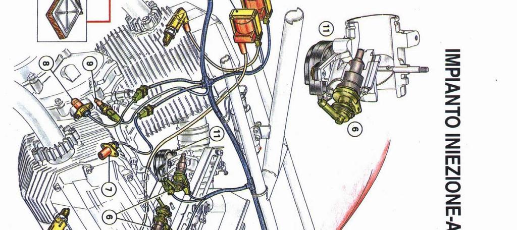
4 FUEL MIXTURE AND IGNITION TIMING CONTROL Control of the air-fuel ratio and the ignition timing is the basic element in optimizing engine performance. The air-fuel ratio is given by the ratio, in terms of weight, of air and gasoline drawn in by the engine. The ideal or stoichiometric ratio is that which produces total combustion. Too much or too little air causes respectively lean or rich mixtures which in turn affect power and fuel consumption (see Fig. 1) and exhaust emissions (see Fig. 2). Electronic ignition timing control allows maximizing engine performance and power, and minimizing fuel consumption and emissions. Electronic ignition timing control combined with electronic fuel supply control allows engine performance to be optimized under such varied conditions as low temperature start up, maximum acceleration and normal cruising at partial load. WEBER INJECTION-IGNITION SYSTEM The Model Alfa/N Weber injection-ignition system, in which engine speed and throttle valve position are used to measure the amount of aspirated air, notes the amount of air and meters the fuel accordingly. Other sensors within the system allow the base strategy to be changed under special operating additions. The engine speed and the throttle valve angle allow the optimal ignition advance to be calculated for every operating condition. The amount of air drawn in by each cylinder for each cycle will depend on the air density in the intake air manifold, the unitary displacement and the volumetric efficiency. Volumetric efficiency is established experimentally on the engine for its entire operational field and this is then programmed in a map in the computer. The injection system is the sequential multi-port type meaning fuel delivery to each cylinder is independent of conditions at the other cylinder. Fuel delivery for one cylinder can occur during the combustion and exhaust phase of the other cylinder. Fuel delivery timing for starting is also in the map in the computer. Ignition is by static induction spark with dwell control in the power module and spark advance curves programmed in the computer. ELEMENTS MAKING UP THE SYSTEM Fuel circuit Fuel is injected into the intake passage for each cylinder upstream of the intake valve. The circuit consists of a tank, pump, filter, pressure regulator valve and electromagnetic injectors. Intake air circuit This consists of an air filter, intake manifold and throttle valve. The throttle position sensor (TPS) is a potentiometer mounted on the bottom of the throttle butterfly valve stem. The barometric pressure sensor and the air temperature sensor are positioned upstream of the throttle valve. Electric circuit This is the circuit used by the computer to adjust the fuel supply and ignition timing to provide optimum performance and reduced emissions under a variety of operating conditions. It includes: a battery, ignition switch, two relays, the computer, the ignition assembly, barometric pressure sensor, air temperature sensor, throttle position potentiometer, two injectors, oil temperature sensor, rpm and timing sensors
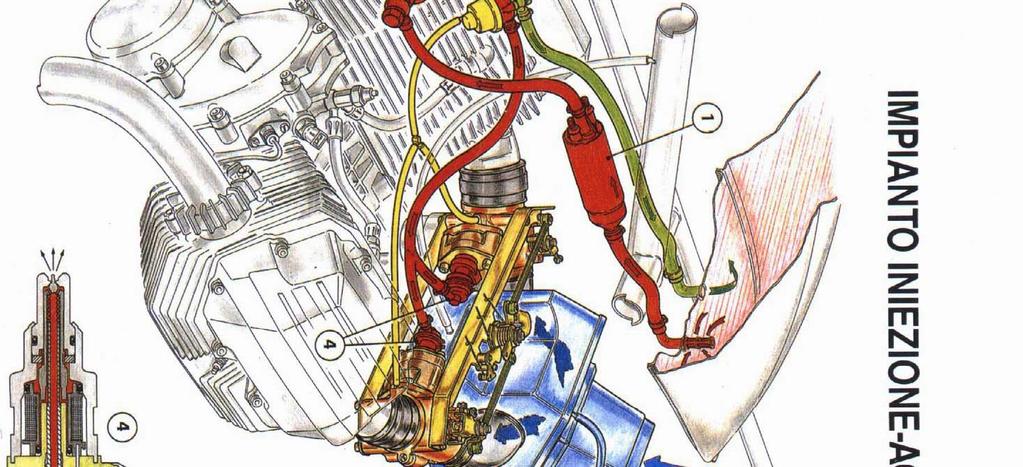
5 FUEL CIRCUIT The electric pump draws fuel from the tank and sends it through a filter to a manifold equipped with feed branches to the injectors. A pressure regulating valve maintains steady fuel pressure by bleeding excess fuel back into the tank. Electric fuel pump This is a roller positive displacement pump with the motor submerged in the fuel. The motor is a permanent magnet carbon brush type. When the impeller is turned by the motor, the fuel is moved from the intake orifice to the delivery port. The amount of fuel is determined by the rollers which adhere to the outer ring while the motor is turning. The pump has a check valve to prevent the fuel circuit emptying when the pump is not running. It is also equipped with an overpressure valve which short-circuits the delivery when the pressure is over 74 psi to prevent the pump motor from overheating. Delivery: 26.5 gal/hour at 44 psi with 12V power supply. The pump draws about 4.5 amps. Note: We recommend strict cleanliness whenever the hoses are installed or removed, or when work is done on the system
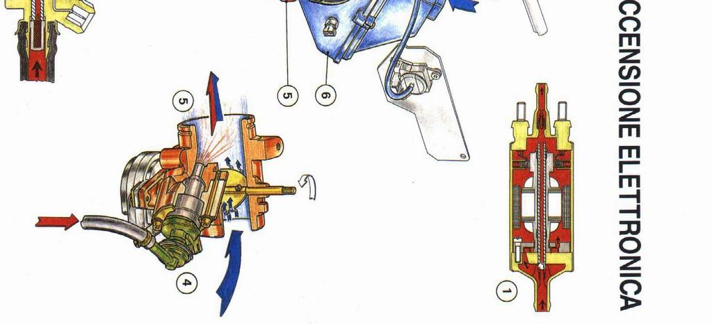
6 Fuel filter This filter has a 10 µm. paper element with a filtering surface of 1200 cm 2. This filter is essential because the injectors are easily clogged by contaminants. The filter is mounted between the pump and the pressure regulating valve. An arrow in the casing indicates flow direction. The filter should be changed every 6,200 miles. Injectors The injectors control the amount of fuel delivered to the engine. The injector is an ON-OFF valve. It has just two operating modes, open or closed. The injector consists of a shell and a pin forming part of the magnetic armature. This pin is pressed up against its seat by a spiral spring whose load is determined by an adjustable push ring. The winding is - 6 -
7 housed in the rear part of the casing while the injector nose is at the front (seal seating and pin guide). The control impulses from the computer create a magnetic field which attracts the armature and thus opens the injector. The amount of fuel injected depends solely on the amount of time the injector is open, assuming constant fuel viscosity and density, and constant pressure differential. This time is established by the computer depending on the engine s operating environment. When the fuel pressure is in the range of psi, the jet breaks into a spray as soon as it leaves the nozzle and forms an arc of approximately 30. Resistance value: 12Ω. If you want to test the injector electrically, apply a maximum of 6 volts for an extremely short period of time. Pressure relief valve This valve maintains steady pressure to the injectors. It is a differential membrane type and is factory set at 36.8 ± 3 psi. The pressurized fuel from the pump exerts pressure against the mobile part (1) which is countered by the calibrated spring (3). When the set pressure is exceeded, the valve cup moves (2) and the excess fuel flows back into the tank. Note that to keep the injector pressure stage steady, the difference between fuel pressure and intake manifold pressure must also be constant. This is achieved by running a tube between the seating of the calibrated governor spring (3) and the intake manifold
8 1) Mobile element 2) Cup valve 3) Calibrated counter-spring AIR CIRCUIT The air circuit is made up of the throttle valve and the air filter assembly. The barometric pressure and air temperature sensors measure conditions in the filter. [The temperature sensor is mounted on the frame in front of the air snorkel on a Cal 1100i] The fuel pressure relief valve measures conditions in the intake manifold. The throttle position reading potentiometer is on the butterfly stem of the throttle valve
9 Intake manifold and throttle valve The amount of air intake is determined by the opening of the butterfly valve (1) in the intake air manifold on each cylinder. The air needed for idling goes through the by-pass channel (2) which has an air adjusting screw (3). Turning this screw varies the amount of air admitted to the manifold to adjust the idle speed. A second screw (4) with a locking nut allows the butterfly valve closing to be adjusted correctly to prevent it hitting up against the surrounding manifold. This screw should not be used to adjust the idle setting. 1) Throttle valve 2) By-pass passage 3) Air regulation screw 4) Butterfly positioning screw - 9 -
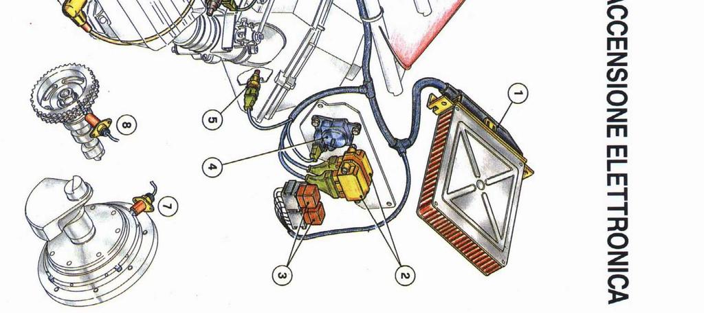
10 ELECTRIC CIRCUIT Relays The Weber injection-ignition system uses two socket mounted automotive relays. [The stock Siemens V23073 relays are trouble prone. Suitable substitutes are Siemens V23074, Bosch , Radio Shack ] The grounding connection of the relay energizing circuit is done in the power pack with a guard to prevent inverting the polarities. These two relays control: fuel pump power supply computer and injector power supply WEBER injection-ignition computer The Weber injection-ignition computer is an electronic digital microprocessor control unit. It controls the parameters for the fuel supply and ignition: amount of fuel delivered to each cylinder injection timing ignition advance To calculate these parameters, the unit uses the following input signals: barometric pressure intake air temperature oil temperature engine speed and timing battery voltage throttle valve position
11 1) CO regulation protection cap to prevent tampering Barometric pressure sensor The sensor is supplied with power by the computer and measures the air pressure in the air filter
12 Air temperature sensor This sensor is an NTC thermistor that measures air temperature in the air filter and sends a signal to the computer. Excessive torque on the mounting screws will damage it. Note: NTC means that the thermistor resistance decreases as the temperature increases (see table). Oil temperature sensor This sensor is an NTC thermistor that measures oil temperature in the valve cover and sends a signal to the computer. Excessive torque on the mounting screws will damage it. Replace the mounting gasket whenever this sensor is removed. Note: NTC means that the thermistor resistance decreases as the temperature increases (see table). Note: Resistance values are identical for both air and oil temperature sensors. Electrical symbol Theoretical data Temperature Resistance C F Kohm Motor RPM sensor This is a variable reluctance sensor. It is mounted on the bell housing facing the flywheel assembly. The flywheel has 4 detector teeth set at 90 to each other. As each tooth passes, the sensor sends an AC signal (see diagram.). The frequency of this signal generates the information on the engine speed
13 PMS (TDC) sensor This is also a variable reluctance sensor. It is mounted on the timing case, senses cam shaft rotation and generates the information needed to know the position of the cylinders in relation to their combustion top dead center

 This potentiometer is supplied with power from the computer to")

14 Coil with power module The ignition is inductive spark. The coil power module unit receives its commands from the computer which determines the ignition advance. The power module (1) also insures that the coil (2) receives constant energy charge. Throttle position potentiometer (TPS) This potentiometer is supplied with power from the computer to which it sends a signal denoting the throttle position. This information is used to adjust fuel metering during starting, idling, acceleration, cruise, and deceleration. This diagram shows the transmission signal sent by the sensor depending on the throttle opening angle
15 OPERATION PHASES Normal operation When the engine is at operating temperature, the computer calculates the timing, the injection timing and duration and the ignition advance by interpolating the programmed maps according to the engine speed. The injection duration (and therefore the amount of fuel) so calculated is then delivered sequentially to each cylinder. The moment when this fuel begins to be delivered to each cylinder is similarly determined according to engine speed. Starting phase As soon as the starter switch is pressed, the computer powers the fuel pump for a few seconds and determines the throttle angle and engine oil temperature. The computer next receives data on the rpm and the timing which allows it to control the injection and ignition. To facilitate starting, the base mix is enriched in accordance with the temperature of the oil. While the engine is being turned over, the ignition advance is fixed (0 ) until the engine has started. Once the engine has started, the ignition timing is controlled by the computer. Acceleration The system increase the rate of fuel delivery during acceleration to improve drivability. Acceleration is detected by a significant change in throttle position angle. The amount of enrichment is also dependant on the oil and air temperatures. Deceleration When the throttle is closed while the engine is working at high level, the fuel supply is cut off for a period. This increases engine braking and reduces fuel consumption and emissions. Deceleration is detected by both throttle position and engine speed. CARBURATION Before adjusting the carburation, if potentiometer A (TPS) has been replaced, removed or is out of adjustment, the first thing to be done is to adjust it. Follow these steps: Potentiometer adjustment disconnect tie-rods B and C from the throttle valves; slacken screw D (butterfly positioning) until the extremity of the beat has been removed away from it; remove the potentiometer s holding screw E check to make sure that the valve flap closes the passage completely; turn and release the casing of potentiometer A : the internal spring will then position the potentiometer correctly; screw down the potentiometer and make sure it does not move while the holding screw E and the washers are being put back. [Note: The above procedure is no longer valid. Revised procedure is as follows: disconnect tie-rod C from the right side throttle valve; Back out screw D (butterfly positioning) until it is no longer effective; loosen the potentiometer s (TPS) holding screws E just enough to allow snug rotation; check to make sure that the valve flap closes the passage completely; connect the negative lead of a digital voltmeter to terminal 17 at the computer or the white wire at the TPS. Connect the positive lead of the meter to terminal 11 of the computer or the red-black wire at the TPS. Start the engine and maintain idle as best as possible using the left cylinder only. Rotate the TPS assembly until a reading of mv is measured on the meter. ; Tighten the TPS mounting screws. Check that voltage is still mv and repeat as necessary.] Adjusting the idle Warm up the engine; disconnect tie-rods B and C ; attach vacuum gauges to the intake manifold of each cylinder; close the by-pass screws M, and with the engine running, adjust the engine speed using screws D and F until you get 800 rpm (use a precision tach). Check to make sure that the vacuum value on both manifolds is the same. Check that the CO value is around 3%; Adjust the two by-pass screws M until you get an operating level of rpm with the same vacuum in each manifold; mount the B tie-rod on the right cylinder throttle control lever (first slacken off screw G to prevent
16 interference from lever H ); mount tie-rod C,, on the left cylinder throttle control lever. To do this turn screw I so that the end of tie-rod C is perfectly inserted into the pin on lever L but without having to move this lever; bring the engine to 1500 rpm with the throttle and check the vacuum on both manifolds. If you have to adjust, use the throttle synchronizing screw I ; release the throttle and recheck the vacuum in both manifolds (they should be the same); replace the anti-tampering plastic caps on the regulating screws for the throttles and by-pass ( F, B, M ); use the exhaust gas analyzer to check the CO which should be %. If this is not the case, carefully remove plug N from the front of the computer and with a 4 mm wide screwdriver adjust the trimmer screw to achieve % CO. Turning the screw clockwise leans the idle mixture. This adjustment changes only the idle mixture. Note: Do not force the adjusting screw beyond its limit stop (it can make a max. of about 3 turns)
17 - 17 -
18 Adjusting choke RPM Make sure the idle speed is correct. With the engine hot, apply full choke. Set the engine speed to 4500 rpm using screw G. When the choke is completely disengaged, screw "G should not contact the accelerator control tie rods. [Note: The term choke here is incorrect. The choke lever merely opens the throttle butterfly valves slightly. It does not enrich the mixture by restricting the air flow or by any other means.] IMPORTANT: Always observes the following precautions to prevent damage to the system: Insure that the ignition switch is in the OFF position before disconnecting the battery. Do not disconnect the battery with the engine running. Make sure the battery cables are in good working condition. Do not use an arc welder on the motorcycle. Do not use auxiliary electrical equipment to start. If you mount anti-theft or any other electric devices on the bike, make sure that they do not interfere with the electronic ignition/injection system in any way. The air/fuel ratio can not be changed with this electronic ignition/injection system. Apply di-electric grease to all electrical contacts to avoid oxidation. CHECKING THE FUEL CIRCUIT Prepare the motorcycle as follows: remove the adapter which attaches the fuel delivery pipe from the pump and insert a gauge to check circuit pressure (Fig. A); turn the ignition key to ON but do not start the engine (this energizes the fuel pump for about 5 seconds). While the pump is running, pressure should be psi. (Fig. A). When the pump stops running, the pressure will go down and stabilize at a pressure below 37 psi
19 Pressure should remain steady at that value for a few minutes. If the pressure shown on the gauge drops in a short time, do the following: turn the ignition key to ON and while the pump is running, close the pipe at position 1 using snappliers (use protective pads on each jaw so as not to damage the tube, Fig. B,). The pressure shown on the gauge will be psi. and should remain steady. If this happens, it means that the drop in pressure was caused by imperfect seal on the fuel pump check valve
20 If the pressure in the circuit continues to drop, repeat the test as follows: close the pipe with the clamping pliers at position 2 (Fig C) on the recirculation pipes and turn the ignition key to the ON position. While the pumping is working, close off the tube also at position 1 the pressure shown on the gauge will be more than 73 psi. and must remain steady at that for a few seconds. If this happens, it means that the drop in pressure was caused by the pressure regulating valve which should be replaced; if the pressure continues to fall with the tube closed off at position 1 and 2, an injector is not closing properly. Identify which one and replace it. If the pressure shown on the gauge is over psi.: follow these steps (Fig. D): disconnect the pressure regulating valve from the recirculation hoses and temporarily install a hose from the regulating valve to a pail. Repeat the test by turning the ignition on. If the pressure is psi, look for trouble in the recirculation lines. If the pressure stays above psi replace the pressure regulating valve. (Check whether the fuel filter had been replaced at 6,200 mile intervals as specified in the manual)
 and turn the ignition on.")
21 If the pressure shown on the gauge Is less than psi. or reaches psi. very slowly, look for an obstruction between the pump and the filter or for something blocking the pump s intake. If none of these causes are involved, crimp the recirculation tube with the clamping pliers (Fig. E. pos. 2) and turn the ignition on. If the pressure jumps beyond 74 psi, replace the pressure regulating valve. If the pressure remains below psi. replace the pump. Note: It Is good operating practice to replace the copper crush washers on the filter fittings after each service operation. The filter itself should be replace after every 6,200 miles. When you are working on the fuel delivery system make sure that no dirt gets into the passages since this could damage the working parts. CHECK LAMP" DIAGNOSlS OF SYSTEM TROUBLES The CHECK LAMP is a simple device that displays abnormalities detected by the computer when the motorcycle was last run. The display consists of a series of flashes, the meaning and diagnosis of which are described below. The IAW fault detection system is autodiagnostic. It detects faults and retains their associated diagnostic codes in memory for display at a later time even if the fault is intermittent. The Check Lamp autodiagnostic system is designed only to monitor the signals from the various input sensors. It is has no capability to control the actuation signals sent to the devices controlled by the computer. IMPORTANT: The diagnostic code(s) are retained in memory as long as the ignition is ON. The codes are lost when the ignition is switched off. Codes transmission: The transmission consists of a series of flashes with pauses of different duration. Every error code is formed by two separate numbers; every number is expressed by an equivalent
22 number of flashes; a longer pause separates the two numbers; the beginning and the ending of the code are shown by a continuous series of flashes (see example page 24). Note: The device transmits only one code pair at a time. lt. is necessary to detect not only the first transmitted code, but also all subsequent codes until the end of the sequence. CONNECTIONS AND WORKING CHECK LAMP A can be connected any time, whether the engine is on or off or the ignition is on or off. The autodiagnosis socket B is located next to the computer C. If the check lamp doesn t light, there is no diagnostic code stored in the computer. Possible causes: 1) There is no code present or the fault can not be determined by the autodiagnostic system. 2) There was a code present but it was erased when the ignition was turned off. Note: It is also possible that a code is stored in the computer, but it can not be displayed on the check lamp. Possible causes: Misconnected check lamp or disconnected autodiagnostic connections; Check lamp itself defective. Check the lamp by turning the ignition on, and then: Cause a fault by disconnecting the oil or air temperature sensor. If the fault is detected, the check lamp works, but the computer didn t store the code. This could indicate a problem somewhere in the system that can not be detected by the autodiagnostic system. If the fault is not detected, check the check lamp connections. Make sure the code was not inadvertently erased by turning the ignition off
23 EXAMPLE Longer pause between the first and the second number CHECK LAMP SIGNALS LEGEND TROUBLE CODE 1.1 RPM signal failure The problem can be in the sensor itself (circuit opened), in the wiring or in the connector (circuit opened). It can also be caused by an excessive air gap. When this fault is intermittently occurs during running, the code 1.1 is present together with the code 1.3. When code 1.1 is present with code 1.3, check the air gap on the bell housing sensor
24 TROUBLE CODE 1.2 Phase signal (TDC) failure The trouble can be in the sensor itself (circuit opened), in the wiring or in the connector (circuit opened). It can also be caused by an excessive air gap. When this fault is intermittently occurs during running the code 1.2 is present together with the code 1.3. When code 1.2 is present with code 1.3, check the air gap on the timing case sensor. TROUBLE CODE 1.3 Incorrect signal sequence 1) If It appears together with the code 1.1 Faulty signal sequence due to a problem with the rpm sensor: RPM sensor itself (disconnected or shorted). RPM sensor wiring (disconnected or shorted). 2) If It appears together with the code 1.2 Faulty signal sequence due to a problem with the TDC sensor: TDC Sensor itself (disconnected or shorted) TDC sensor wiring (disconnected or shorted). 3) If It is not together with the code 1.1 or code 1.2 Faulty signal sequence due to: Faulty air gaps (RPM & TDC sensors) Irregular air gap caused by a misalignment or eccentricity of the timing gear or flywheel assembly. Note: Code 1.3 is only detectable with the engine ON. TROUBLE CODE 2.1 Faulty air temperature signal The trouble can be: Air temperature sensor itself (disconnected or shorted) Air temperature sensor wiring or connector (disconnected or shorted) TROUBLE CODE 2.3 Faulty oil temperature signal The trouble can be: Oil temperature sensor itself (disconnected or shorted) Oil temperature sensor wiring or connector (disconnected or shorted) TROUBLE CODE 3.2 Faulty signal from the barometric pressure sensor. The trouble can be: Defective pressure sensor. Damaged or defective connections/wiring. TROUBLE CODE 3.3 Faulty signal from the throttle potentiometer. The trouble can be: Defective TPS potentiometer. Damaged or defective wiring/connections
25 - 25 -
26 - 26 -
27 - 27 -
FUEL INJECTION SYSTEM - MULTI-POINT
 FUEL INJECTION SYSTEM - MULTI-POINT 1988 Jeep Cherokee 1988 Electronic Fuel Injection JEEP MULTI-POINT 4.0L Cherokee, Comanche, Wagoneer DESCRIPTION The Multi-Point Electronic Fuel Injection (EFI) system
4.0L CEC SYSTEM Jeep Cherokee DESCRIPTION OPERATION FUEL CONTROL DATA SENSORS & SWITCHES
 4.0L CEC SYSTEM 1988 Jeep Cherokee 1988 COMPUTERIZED ENGINE Controls ENGINE CONTROL SYSTEM JEEP 4.0L MPFI 6-CYLINDER Cherokee, Comanche & Wagoneer DESCRIPTION The 4.0L engine control system controls engine
1998 ENGINE PERFORMANCE. General Motors Corp. - Basic Diagnostic Procedures - 5.7L
 INTRODUCTION 1998 ENGINE PERFORMANCE General Motors Corp. - Basic Diagnostic Procedures - 5.7L The following diagnostic steps will help prevent overlooking a simple problem. This is also where to begin
G - TESTS W/CODES - 2.2L
 G - TESTS W/CODES - 2.2L 1994 Toyota Celica 1994 ENGINE PERFORMANCE Toyota 2.2L Self-Diagnostics Celica INTRODUCTION If no faults were found while performing F - BASIC TESTING, proceed with self-diagnostics.
Fuel Metering System Component Description
 1999 Chevrolet/Geo Tahoe - 4WD Fuel Metering System Component Description Purpose The function of the fuel metering system is to deliver the correct amount of fuel to the engine under all operating conditions.
Powertrain DTC Summaries EOBD
 Powertrain DTC Summaries Quick Reference Diagnostic Guide Jaguar X-TYPE 2.0 L 2002.25 Model Year Refer to page 2 for important information regarding the use of Powertrain DTC Summaries. Jaguar X-TYPE 2.0
(3) (4) (6) (5) (10) (9) (8) (7)
 (4) (6) (5) (10) (9) (8) (7)") 3. Fuel System A: GENERAL The fuel pressurized by the fuel tank inside pump is delivered to each fuel injector by way of the fuel pipe and fuel filter. Fuel injection pressure is regulated to an optimum
3. Fuel System A: GENERAL The fuel pressurized by the fuel tank inside pump is delivered to each fuel injector by way of the fuel pipe and fuel filter. Fuel injection pressure is regulated to an optimum
Common rail injection system
 Common rail injection system Pressure limiting valve The pressure limiting valve is located directly on the high-pressure fuel rail. Its function is to limit maximum pressure in the high-pressure fuel
MULTIPOINT FUEL INJECTION (MPI) <4G9>
 <4G9>") MULTIPOINT FUEL INJECTION (MPI) 13C-1 MULTIPOINT FUEL INJECTION (MPI) CONTENTS GENERAL................................. 2 Outline of Changes............................ 2 GENERAL INFORMATION...................
MULTIPOINT FUEL INJECTION (MPI) 13C-1 MULTIPOINT FUEL INJECTION (MPI) CONTENTS GENERAL................................. 2 Outline of Changes............................ 2 GENERAL INFORMATION...................
REFERENCE MATERIAL: PROGRAM CODE - undefined
 REFERENCE MATERIAL: PROGRAM CODE - undefined - Revised 2001-2001 by Harley-Davidson Motor Company - All Rights reserved General Operating Parameters for Open and Closed Loop Running How does the Buell
Powertrain DTC Summaries EOBD
 Powertrain DTC Summaries Quick Reference Diagnostic Guide Jaguar S-TYPE V6, V8 N/A and V8 SC 2002.5 Model Year Refer to pages 2 9 for important information regarding the use of Powertrain DTC Summaries.
QUICK FUEL TECHNOLOGY HOT ROD SERIES CARBURETORS SLAYER SERIES CARBURETORS SUPER STREET SERIES CARBURETORS
 QUICK FUEL TECHNOLOGY Installation Instructions HOT ROD SERIES CARBURETORS SLAYER SERIES CARBURETORS SUPER STREET SERIES CARBURETORS HR-580-VS 580 CFM Vac. Secondary!!! SS-680-VS 680 CFM Vac. Secondary
Error codes Diagnostic plug Read-out Reset Signal Error codes
 Error codes Diagnostic plug Diagnostic plug: 1 = Datalink LED tester (FEN) 3 = activation error codes (TEN) 4 = positive battery terminal (+B) 5 = ground Read-out -Connect LED tester to positive battery
Diagnostic Trouble Code (DTC) memory, checking and erasing
 memory, checking and erasing") Page 1 of 49 01-12 Diagnostic Trouble Code (DTC) memory, checking and erasing Check DTC Memory (function 02) - Connect VAS5051 tester Page 01-7 and select vehicle system "01 - Engine electronics". Engine
Page 1 of 49 01-12 Diagnostic Trouble Code (DTC) memory, checking and erasing Check DTC Memory (function 02) - Connect VAS5051 tester Page 01-7 and select vehicle system "01 - Engine electronics". Engine
WEBER CARBURETOR TROUBLESHOOTING GUIDE
 This guide is to help pinpoint problems by diagnosing engine symptoms associated with specific vehicle operating conditions. The chart will guide you step by step to help correct these problems. For successful
Sensors & Controls. Everything you wanted to know about gas engine ignition technology but were too afraid to ask.
 Everything you wanted to know about gas engine ignition technology but were too afraid to ask. Contents 1. Introducing Electronic Ignition 2. Inductive Ignition 3. Capacitor Discharge Ignition 4. CDI vs
THE CARBURETOR: THE ADDITIONAL SYSTEMS
 THE CARBURETOR: THE ADDITIONAL SYSTEMS From the acceleration pump to the power jet: the special configuration of circuits that apply to some carburetor models As stated in the previous article, a carburetor
Truck and Transport IP Red Seal Practice Exam PRACTICE EXAM 4
 Truck and Transport IP Red Seal Practice Exam PRACTICE EXAM 4 1. Which of these sensors directly measures engine load? a. Manifold absolute pressure sensor. b. Coolant sensor (ECT). c. Vehicle speed sensor.
SYTY Trouble Code: ALDL INFORMATION
 SYTY Trouble Code: ALDL INFORMATION A -- Ground G -- Fuel Pump B -- Diagnostic Terminal H -- Brake Sense Speed Input F -- TCC M -- Serial Data (special tool needed - Do Not Use) For ECM Trouble Codes,
Propane and Gasoline Electronic Fuel Injection
 Zenith Electronic Engine Management System Propane and Gasoline Electronic Fuel Injection 1 Slide 1 2 Slide 2 Home Page System Advantages Block Diagram, Electronic Control Unit Inputs Output Controls System
DESCRIPTION Chevrolet Chevy Van 5.7L Eng G20. Service Manual: FUEL INJECTION SYSTEM - TBI
 Service Manual: FUEL INJECTION SYSTEM - TBI DESCRIPTION 1989 Chevrolet Chevy Van 5.7L Eng G20 The throttle body fuel injection system consists of 7 major sub-assemblies: fuel supply system, throttle body
Powertrain Control Software
 2007 PCED On Board Diagnostics SECTION 1: Description and Operation Procedure revision date: 03/29/2006 Powertrain Control Software Computer Controlled Shutdown The powertrain control module (PCM) controls
3. Fuel System FUEL SYSTEM FUEL INJECTION (FUEL SYSTEM) A: GENERAL. FU(STi)-7
 A: GENERAL. FU(STi)-7") W1860BE.book Page 7 Tuesday, January 28, 2003 11:01 PM 3. Fuel System A: GENERAL The fuel pressurized by the fuel tank inside pump is delivered to each fuel injector by way of the fuel pipe and fuel filter.
W1860BE.book Page 7 Tuesday, January 28, 2003 11:01 PM 3. Fuel System A: GENERAL The fuel pressurized by the fuel tank inside pump is delivered to each fuel injector by way of the fuel pipe and fuel filter.
AN EXPLANATION OF CIRCUITS CARTER YH HORIZONTAL CLIMATIC CONTROL CARBURETER
 AN EXPLANATION OF CIRCUITS CARTER YH HORIZONTAL CLIMATIC CONTROL CARBURETER The Carter Model YH carbureter may be compared with a Carter YF downdraft carbureter with the circuits rearranged to operate
5-2 FUEL SYSTEM AND THROTTLE BODY FUEL SYSTEM FUEL DELIVERY SYSTEM The fuel delivery system consists of the fuel tank, fuel pump, fuel filters, fuel f
 FUEL SYSTEM AND THROTTLE BODY 5-1 FUEL SYSTEM AND THROTTLE BODY I CONTENTS FUEL SYSTEM 5-2 FUEL DELIVERY SYSTEM 5-2 FUEL PUMP 5-3 FUEL PRESSURE REGULATOR 5-4 FUEL INJECTOR 5-4 FUEL PUMP CONTROL SYSTEM
Fuel System Diagnosis
 1996 Chevrolet Impala Caprice, Impala, Roadmaster (VIN B) Service Manual Engine Engine Controls - 4.3L (Caprice Only) and 5.7L Diagnostic Information and Procedures Document ID: 37723 Fuel System Diagnosis
TUNING Training Course Material 2014 Valid for Diag4Bike V14 only On-line Multimedia User Manual is under preparation.
 TUNING Training Course Material 2014 Valid for Diag4Bike V14 only On-line Multimedia User Manual is under preparation www.diag4bike.eu 1 TUNING STRATEGY Tuning system is based on DIAG4BIKE diagnostics
BASIC DIAGNOSTIC PROCEDURES
 BASIC DIAGNOSTIC PROCEDURES 2001 Chevrolet Camaro 2001 ENGINE PERFORMANCE Basic Diagnostic Procedures - Cars Except Metro & Prizm MODEL IDENTIFICATION MODEL IDENTIFICATION Body Code (1) Model C... Park
CARBURETOR SERVICE INFORMATION TROUBLESHOOTING THROTTLE VALVE DISASSEMBLY THROTTLE VALVE INSTALLATION...
 11 CARBURETOR SERVICE INFORMATION... 11-2 TROUBLESHOOTING... 11-2 THROTTLE VALVE DISASSEMBLY... 11-3 THROTTLE VALVE INSTALLATION... 11-4 CARBURETOR REMOVAL... 11-5 AUTO BYSTARTER... 11-6 FLOAT CHAMBER...
IGNITION SYSTEM 8D - 1 IGNITION SYSTEM TABLE OF CONTENTS
 LH IGNITION SYSTEM 8D - 1 IGNITION SYSTEM TABLE OF CONTENTS page AND IGNITION SYSTEM...1 SPARK PLUGS-PLATINUM....1 COIL ON PLUG...1 CRANKSHAFT POSITION SENSOR....2 CAMSHAFT POSITION SENSOR....3 KNOCK SENSOR....5
Manual. Engine SOLO type i
 for the Engine SOLO type Serial - no.... Manufactured... Aircraft - type... Registration no.... Owner... Log of revisions no. Edition date revised page no. date of entry 1 01.09.2010 1-9 01. September
H - TESTS W/O CODES Nissan 240SX INTRODUCTION TROUBLE SHOOTING SYMPTOMS DIAGNOSIS WILL NOT START
 H - TESTS W/O CODES 1990 Nissan 240SX 1990 ENGINE PERFORMANCE Trouble Shooting - No Codes Nissan; 240SX, Axxess, Maxima, Pathfinder, Pickup, Pulsar, Sentra, Van, INTRODUCTION Before diagnosing symptoms
PIERBURG. Carburetor: 2E3
 PIERBURG Carburetor: 2E3 1 fast idle adjusting screw 2 throttle lever 3 fuel mixture adjusting screw 4 main body 5 idle cut off valve 6 stop screw 7 accelerator pump cover 8 diaphragm 9 spring 10 valve
Powertrain DTC Summaries OBD II
 Powertrain DTC Summaries Quick Reference Diagnostic Guide Jaguar X-TYPE 2.5L and 3.0L 2002 Model Year Revised January, 2002: P0706, P0731, P0732, P0733, P0734, P0735, P0740, P1780 POSSIBLE CAUSES Revised
Motronic ignition system, servicing
 Page 1 of 25 28-2 Motronic ignition system, servicing Note: Motronic Engine Control Module (ECM) J220* with connector page 24-9, item 16. 1 - Highvoltage ignition cable Ignition secondary circuit Check
A. Perform a vacuum gauge test to determine engine condition and performance.
 ENGINE REPAIR UNIT 2: ENGINE DIAGNOSIS, REMOVAL, AND INSTALLATION LESSON 2: ENGINE DIAGNOSTIC TESTS NOTE: Testing the engine s mechanical condition is required when the cause of a problem is not located
Typical Install Instructions
 Typical Install Instructions Read & understand all steps of these instructions before beginning this installation. WEBER Conversion Kit, VW T-1/2, up to 1835cc 32 / 36 DFEV Weber Carburetor These instructions
Basic Requirements. ICE Fuel Metering. Mixture Quality Requirements. Requirements for Metering & Mixing
 Basic Requirements ICE Fuel Metering Dr. M. Zahurul Haq Professor Department of Mechanical Engineering Bangladesh University of Engineering & Technology (BUET) Dhaka-1000, Bangladesh zahurul@me.buet.ac.bd
Part #82064 Add-A-Stage EFI Nitrous System
 1 INSTRUCTIONS Part #82064 Add-A-Stage EFI Nitrous System Thank you for choosing products; we are proud to be your manufacturer of choice. Please read this instruction sheet carefully before beginning
G - TESTS W/CODES Nissan 240SX * PLEASE READ THIS FIRST * INTRODUCTION SELF-DIAGNOSTIC SYSTEM DESCRIPTION HARD FAILURES INTERMITTENT FAILURES
 G - TESTS W/CODES 1990 Nissan 240SX 1990 ENGINE PERFORMANCE Self-Diagnostics Nissan 240SX and Axxess * PLEASE READ THIS FIRST * NOTE: This article has been revised according to Technical Service Bulletin
DTC P0171 SYSTEM TOO LEAN (BANK 1) DTC P0174 SYSTEM TOO LEAN (BANK 2)
 DTC P0174 SYSTEM TOO LEAN (BANK 2)") 05498 DIAGNOSTICS DTC P0171 SYSTEM TOO LEAN (BANK 1) 05EXR06 DTC P0172 SYSTEM TOO RICH (BANK 1) DTC P0174 SYSTEM TOO LEAN (BANK 2) DTC P0175 SYSTEM TOO RICH (BANK 2) CIRCUIT DESCRIPTION The fuel trim is
05498 DIAGNOSTICS DTC P0171 SYSTEM TOO LEAN (BANK 1) 05EXR06 DTC P0172 SYSTEM TOO RICH (BANK 1) DTC P0174 SYSTEM TOO LEAN (BANK 2) DTC P0175 SYSTEM TOO RICH (BANK 2) CIRCUIT DESCRIPTION The fuel trim is
ACCEL Distributor Model #A557
 FORM 1627 REV1 INSTALLATION INSTRUCTIONS ACCEL Distributor Model #A557 CAUTION: CAREFULLY READ INSTRUCTIONS BEFORE PROCEEDING. NOT LEGAL FOR USE OR SALE ON POLLUTION CONTROLLED VECHICLES OVERVIEW ACCEL
5. Control System CONTROL SYSTEM FUEL INJECTION (FUEL SYSTEM) A: GENERAL FU(H4DOTC)-29
 A: GENERAL FU(H4DOTC)-29") W1860BE.book Page 29 Tuesday, January 28, 2003 11:01 PM 5. Control System A: GENERAL The ECM receives signals from various sensors, switches, and other control modules. Using these signals, it determines
W1860BE.book Page 29 Tuesday, January 28, 2003 11:01 PM 5. Control System A: GENERAL The ECM receives signals from various sensors, switches, and other control modules. Using these signals, it determines
Powertrain DTC Summaries EOBD
 Powertrain DTC Summaries Quick Reference Diagnostic Guide Jaguar X-TYPE 2.5L and 3.0L 2001.5 Model Year Revised January, 2002: P0706, P0731, P0732, P0733, P0734, P0735, P0740, P1780 POSSIBLE CAUSES Revised
Idle Air Control (IAC) System Diagnosis
 System Diagnosis") 2001 Oldsmobile Alero Idle Air Control (IAC) System Diagnosis Circuit Description The idle air control (IAC) valve is located in the throttle body. It consists of a movable pintle, driven by a gear attached
2001 Oldsmobile Alero Idle Air Control (IAC) System Diagnosis Circuit Description The idle air control (IAC) valve is located in the throttle body. It consists of a movable pintle, driven by a gear attached
EMISSION CONTROL SYSTEM
 XJ EMISSION CONTROL SYSTEM 25-1 EMISSION CONTROL SYSTEM CONTENTS EXHAUST EMISSION CONTROLS 2.5L DIESEL ENGINE... 6 ON-BOARD DIAGNOSTICS 2.5L DIESEL ENGINE... 1 ON-BOARD DIAGNOSTICS 2.5L DIESEL ENGINE INDEX
Rover SD1 Efi System Fuel Supply Components - Explanation and Testing of the Fuel Pump, Filter and Fuel Pressure Regulator
 Rover SD1 Efi System Fuel Supply Components - Explanation and Testing of the Fuel Pump, Filter and Fuel Pressure Regulator Introduction Some of the notes here are repetitious in order to review the components
INSIDE YOUR HOLLEY CARBURETOR FUEL INLET SYSTEM
 INSIDE YOUR HOLLEY CARBURETOR The carburetor is quite simply a fuel metering device that operates under the logical and straightforward laws of physics. It has evolved over the years from a very simple
The PCM is the on-board computer which receives input from various sensors and, with this information, controls various engine & emissions control
 The PCM is the on-board computer which receives input from various sensors and, with this information, controls various engine & emissions control actuators. The PCM has various memories within it. These
BODY ELECTRICAL SYSTEM
 BODY ELECTRICAL SYSTEM 8-1 SECTION 8 BODY ELECTRICAL SYSTEM WARNING: For vehicles equipped with Supplemental Restraint (Air Bag) System: Service on and around the air bag system components or wiring must
1999 Toyota RAV ACCESSORIES & EQUIPMENT Cruise Control Systems - RAV4
 1999 ACCESSORIES & EQUIPMENT Cruise Control Systems - RAV4 DESCRIPTION WARNING: Deactivate air bag system before performing any service operation. See AIR BAG RESTRAINT SYSTEMS article. DO NOT apply electrical
1. Anti-lock Brake System (ABS)
") W1860BE.book Page 2 Tuesday, January 28, 2003 11:01 PM 1. Anti-lock Brake System () A: FEATURE The 5.3i type used in the Impreza has a hydraulic control unit, an control module, a valve relay and a motor
W1860BE.book Page 2 Tuesday, January 28, 2003 11:01 PM 1. Anti-lock Brake System () A: FEATURE The 5.3i type used in the Impreza has a hydraulic control unit, an control module, a valve relay and a motor
Diagnostic Trouble Code (DTC) table
 table") Page 1 of 40 01-19 Diagnostic Trouble Code (DTC) table Note: When malfunctions occur in monitored sensors or components, Diagnostic Trouble Codes (DTCs) are stored in DTC memory with a description of the
Page 1 of 40 01-19 Diagnostic Trouble Code (DTC) table Note: When malfunctions occur in monitored sensors or components, Diagnostic Trouble Codes (DTCs) are stored in DTC memory with a description of the
EMISSION CONTROL VISUAL INSPECTION PROCEDURES
 EMISSION CONTROL VISUAL INSPECTION PROCEDURES 1992 Infiniti G20 1983-98 GENERAL INFORMATION Emission Control Visual Inspection Procedures All Models * PLEASE READ THIS FIRST * This article is provided
F - BASIC TESTING Toyota Celica INTRODUCTION PRELIMINARY INSPECTION & ADJUSTMENTS VISUAL INSPECTION MECHANICAL INSPECTION
 F - BASIC TESTING 1994 Toyota Celica 1994 ENGINE PERFORMANCE Toyota 4-Cylinder Basic Diagnostic Procedures Celica INTRODUCTION The following diagnostic steps will help prevent overlooking a simple problem.
Chapter 4 Part D: Fuel and exhaust systems - Magneti Marelli injection
 4D 1 Chapter 4 Part D: Fuel and exhaust systems - Magneti Marelli injection Contents Accelerator cable - removal and..................... 11 Air cleaner element - renewal..............................
13A-1 FUEL CONTENTS MULTIPOINT FUEL INJECTION (MPI) FUEL SUPPLY... 13B
 FUEL SUPPLY... 13B") 13A-1 FUEL CONTENTS MULTIPOINT FUEL INJECTION (MPI)... 13A FUEL SUPPLY... 13B 13A-2 MULTIPOINT FUEL INJECTION (MPI) CONTENTS GENERAL INFORMATION... 3 SERVICE SPECIFICATIONS... 6 SEALANT... 6 SPECIAL TOOLS...
13A-1 FUEL CONTENTS MULTIPOINT FUEL INJECTION (MPI)... 13A FUEL SUPPLY... 13B 13A-2 MULTIPOINT FUEL INJECTION (MPI) CONTENTS GENERAL INFORMATION... 3 SERVICE SPECIFICATIONS... 6 SEALANT... 6 SPECIAL TOOLS...
SERVICE MANUAL. Common Rail System for HINO J08C/J05C Type Engine Operation. For DENSO Authorized ECD Service Dealer Only
 For DENSO Authorized ECD Service Dealer Only Diesel Injection Pump No. E-03-03 SERVICE MANUAL Common Rail System for HINO J08C/J05C Type Engine Operation June, 2003-1 00400024 GENERAL The ECD-U2 was designed
EMISSION CONTROL SYSTEM
 XJ EMISSION CONTROL SYSTEM 25-1 EMISSION CONTROL SYSTEM TABLE OF CONTENTS ON-BOARD DIAGNOSTICS 2.5L DIESEL ENGINE... 1 EXHAUST EMISSION CONTROLS 2.5L DIESEL ENGINE... 6 ON-BOARD DIAGNOSTICS 2.5L DIESEL
F - BASIC TESTING Volvo 850 INTRODUCTION PRELIMINARY INSPECTION & ADJUSTMENTS VISUAL INSPECTION MECHANICAL INSPECTION
 F - BASIC TESTING 1995 Volvo 850 1995 ENGINE PERFORMANCE Volvo - Basic Diagnostic Procedures 850 INTRODUCTION NOTE: In this article, Engine Control Module (ECM) may also be referred to as Engine Control
ANTI-LOCK BRAKE SYSTEM - REAR WHEEL
 ANTI-LOCK BRAKE SYSTEM - REAR WHEEL 1994 Nissan Pickup 1994 BRAKES Nissan - Rear Anti-Lock Pathfinder, Pickup DESCRIPTION In 2WD mode, Rear Anti-Lock Brake System (RABS) helps the driver to maintain steering
DASH RETRIEVED FAULT CODES C ONVENTIONAL FS65 SAF T LINER C2, C2E H YBRID SAF T LINER HDX, HD, ER SAF T LINER EF, EFX A LL Y EARS
 DASH RETRIEVED FAULT CODES C ONVENTIONAL FS65 SAF T LINER C2, C2E H YBRID SAF T LINER HD, HD, ER SAF T LINER EF, EF A LL Y EARS PAGE INTENTIONALLY LEFT BLANK TABLE OF CONTENTS EARLY PRODUCTS: J1587/J1708
ANTI-LOCK BRAKE SYSTEM
 ANTI-LOCK BRAKE SYSTEM 1993 Mitsubishi Diamante 1993 BRAKES Mitsubishi - Anti-Lock Brake System Diamante DESCRIPTION The Anti-Lock BRAKE SYSTEM (ABS) is designed to prevent wheel lock-up during heavy braking.
THE IDLE CIRCUIT AND THE PROGRESSION. We have seen how in a "basic"
 THE IDLE CIRCUIT AND THE PROGRESSION Manufacture and operation of two very important systems, which allow the practical use of a carburetor for motorcycles We have seen how in a "basic" (simplified) carburetor,
GROUP 17 CONTENTS WARNINGS REGARDING SERVICING OF SUPPLEMENTAL RESTRAINT SYSTEM (SRS) EQUIPPED VEHICLES
 EQUIPPED VEHICLES") 17-1 GROUP 17 CONTENTS ENGINE CONTROL 17-4 GENERAL DESCRIPTION 17-4 ENGINE CONTROL SYSTEM DIAGNOSIS 17-4 INTRODUCTION TO ENGINE CONTROL SYSTEM DIAGNOSIS 17-4 ENGINE CONTROL SYSTEM DIAGNOSTIC TROUBLESHOOTING
17-1 GROUP 17 CONTENTS ENGINE CONTROL 17-4 GENERAL DESCRIPTION 17-4 ENGINE CONTROL SYSTEM DIAGNOSIS 17-4 INTRODUCTION TO ENGINE CONTROL SYSTEM DIAGNOSIS 17-4 ENGINE CONTROL SYSTEM DIAGNOSTIC TROUBLESHOOTING
HFM Gasoline Injection and Ignition System
 07.5-0030 HFM Design and Function HFM Gasoline Injection and Ignition System A. General The HFM gasoline injection and ignition system is a further development of the LH and EZL. The basic system of the
2012 Chevy Truck Equinox FWD L4-2.4L Vehicle > Locations > Components
 2012 Chevy Truck Equinox FWD L4-2.4L Vehicle > Locations > Components 2012 Chevy Truck Equinox FWD L4-2.4L Vehicle > Powertrain Management > Fuel Delivery and Air Induction > Description and Operation
Contents. Preface... xiii Introduction... xv. Chapter 1: The Systems Approach to Control and Instrumentation... 1
 Contents Preface... xiii Introduction... xv Chapter 1: The Systems Approach to Control and Instrumentation... 1 Chapter Overview...1 Concept of a System...2 Block Diagram Representation of a System...3
F - BASIC TESTING Infiniti G20 INTRODUCTION PRELIMINARY INSPECTION & ADJUSTMENTS VISUAL INSPECTION MECHANICAL INSPECTION
 F - BASIC TESTING 1992 Infiniti G20 1992 ENGINE PERFORMANCE Infiniti Basic Diagnostic Procedures G20, M30, Q45 INTRODUCTION The following diagnostic steps will help prevent overlooking a simple problem.
Carburetor Instructions
 Carburetor Instructions for HUDSON SUPER SIX ESSEX SIX CYLINDER Hudson Motor Car Co. DETROIT, U.S.A. Carburetor The carburetor is a device for metering correct amounts of fuel and air for the various
DTC P0341 Camshaft Position (CMP) Sensor Performance
 Sensor Performance") Page 1 of 5 1999 Buick Century Century, Regal VIN W Service Manual Document ID: 345654 DTC P0341 Camshaft Position (CMP) Sensor Performance Circuit Description During cranking, the Ignition Control Module
Page 1 of 5 1999 Buick Century Century, Regal VIN W Service Manual Document ID: 345654 DTC P0341 Camshaft Position (CMP) Sensor Performance Circuit Description During cranking, the Ignition Control Module
ENGINE AND EMISSION CONTROL
 17-1 GROUP 17 ENGINE AND EMISSION CONTROL CONTENTS ENGINE CONTROL 17-2 GENERAL INFORMATION 17-2 AUTO-CRUISE CONTROL SYSTEM 17-3 GENERAL INFORMATION 17-3 CONSTRUCTION AND OPERATION 17-5 17-7 GENERAL INFORMATION
SPN 106. Suspect Parameter Number (SPN) and Failure Mode Indicator (FMI) Description
 and Failure Mode Indicator (FMI) Description") SPN 106 Suspect Parameter Number (SPN) and Failure Mode Indicator (FMI) Description SPN FMI Description Possible Causes 106 3 MAP Sensor Signal Voltage High Open/high resistance in low reference circuit
SPN 106 Suspect Parameter Number (SPN) and Failure Mode Indicator (FMI) Description SPN FMI Description Possible Causes 106 3 MAP Sensor Signal Voltage High Open/high resistance in low reference circuit
Setup Tabs. Basic Setup: Advanced Setup:
 Setup Tabs Basic Setup: Password This option sets a password that MUST be entered to re-enter the system. Note: ProEFI can NOT get you into the calibration if you lose this password. You will have to reflash
 Page 1 of 7 DTC P0016 CRANKSHAFT POSITION-CAMSHAFT POSITION CORRELATION (BANK 1 SENSOR A) COMPONENT LOCATION 2008 Kia Sorento 3.3L Eng LX Fig 1: Identifying Crankshaft Position-Camshaft Position Correlation
ARTICLE BEGINNING INTRODUCTION SELF-DIAGNOSTIC SYSTEM RETRIEVING DTCS ENGINE PERFORMANCE Volkswagen Self-Diagnostics - Gasoline
 Article Text ARTICLE BEGINNING 1996 ENGINE PERFORMANCE Volkswagen Self-Diagnostics - Gasoline Cabrio, Golf III, GTI, Jetta III, Passat INTRODUCTION If no faults were found while performing preliminary
Quality Management After-Sales. WORKSHOP MANUAL ECU-CONTROLLED CARBURETION SYSTEM EURO 4 DELL'ORTO
 Quality Management After-Sales. WORKSHOP MANUAL - ECU-CONTROLLED CARBURETION SYSTEM EURO 4 DELL'ORTO TABLE OF CONTENTS TABLE OF CONTENTS SYNOPTICS... 3 GENERAL VIEW... 4 DETAILED DESCRIPTION OF COMPONENTS...
ENGINE AND EMISSION CONTROL
 17-1 GROUP 17 ENGINE AND EMISSION CONTROL CONTENTS ENGINE CONTROL.......... 17-3 GENERAL DESCRIPTION...... 17-3 ENGINE CONTROL SYSTEM DIAGNOSIS.................. 17-3 INTRODUCTION TO ENGINE CONTROL SYSTEM
CAUTION: CAREFULLY READ INSTRUCTIONS BEFORE PROCEEDING
 Daytona Sensors LLC Engine Controls and Instrumentation Systems Installation Instructions for Wide-Band Exhaust Gas Oxygen Sensor Interface CAUTION: CAREFULLY READ INSTRUCTIONS BEFORE PROCEEDING OVERVIEW
There are predominantly two reasons for excessive fuelling: increased fuel pressure and extended injector duration. Figure 1.0
 In this tutorial we look at the actuators and components that affect the vehicles exhaust emissions when the electronically controlled fuel injection system is found to be over fuelling. There are predominantly
Chrysler Electronic Ignition System
 1 of 11 1/6/2010 11:02 PM Chrysler Electronic Ignition System Classic Winnebago's Post by: DaveVA78Chieftain on August 13, 2009, 10:15 PM Components The Chrysler Electronic Ignition System consists of
ELECTRONIC FUEL INJECTION
 Table of Contents ELECTRONIC FUEL INJECTION Section 3B - Troubleshooting and Diagnostics TROUBLESHOOTING AND DIAGNOSTICS Specifications........................... 3B-1 Special Tools...........................
Simple Carburettor Fuel System for a Piston Engine. And how it works
 Simple Carburettor Fuel System for a Piston Engine And how it works Inlet Exhaust Tank PISTON ENGINE Carburettor Fuel System Filler Cap COCKPIT FUEL GAUGE E FUEL 1/2 F Filler Neck Tank Cavity FUEL LEVEL
Timing is everything with internal combustion engines By: Bernie Thompson
 Timing is everything with internal combustion engines By: Bernie Thompson As one goes through life, it is said that timing is everything. In the case of the internal combustion engine, this could not be
HOWELL INSTALLATION MANUAL. Tuned Port Or LT-1 Fuel Injection Harness ( )
") HOWELL ENGINE DEVELOPMENTS, INC. FUEL INJECTION APPLICATIONS INSTALLATION MANUAL Tuned Port Or LT-1 Fuel Injection Harness (1985-1992) Howell Engine Developments, Inc. 6201 Industrial Way Marine City,
HOWELL ENGINE DEVELOPMENTS, INC. FUEL INJECTION APPLICATIONS INSTALLATION MANUAL Tuned Port Or LT-1 Fuel Injection Harness (1985-1992) Howell Engine Developments, Inc. 6201 Industrial Way Marine City,
Lotus Service Notes Section EMR
 ENGINE MANAGEMENT SECTION EMR Lotus Techcentre Sub-Section Page Diagnostic Trouble Code List EMR.1 3 Component Function EMR.2 7 Component Location EMR.3 9 Diagnostic Guide EMR.4 11 CAN Bus Diagnostics;
Idle Air Control (IAC) System Diagnosis
 System Diagnosis") Page 1 of 6 2002 Chevrolet Tahoe - 4WD Avalanche, Escalade, Suburban, Tahoe, Yukon VIN C/K Service Manual Engine Engine Controls - 4.8L, 5.3L, and 6.0L Diagnostic Information and Procedures Document ID:
Page 1 of 6 2002 Chevrolet Tahoe - 4WD Avalanche, Escalade, Suburban, Tahoe, Yukon VIN C/K Service Manual Engine Engine Controls - 4.8L, 5.3L, and 6.0L Diagnostic Information and Procedures Document ID:
HIGH FUEL PRESSURE LINE
 16 07 HIGH FUEL PRESSURE LINE High Pressure Pump Description This pump generates high fuel pressure and is driven by timing chain (radial plunger principle). This pump pressurizes the fuel to approx. 1600
ALTERNATOR - BOSCH 35/75-AMP & 40/90-AMP
 ALTERNATOR - BOSCH 35/75-AMP & 40/90-AMP 1988 Chrysler LeBaron Convert/Coupe 1988 ALTERNATORS & REGULATORS Chrysler Motors - Bosch 35/75 & 40/90 Amp Alternator All Models DESCRIPTION The charging system
E - THEORY/OPERATION - TURBO
 E - THEORY/OPERATION - TURBO 1995 Volvo 850 1995 ENGINE PERFORMANCE Volvo - Theory & Operation 850 - Turbo INTRODUCTION This article covers basic description and operation of engine performance-related
5. Control System CONTROL SYSTEM FUEL INJECTION (FUEL SYSTEM) A: GENERAL. FU(STi)-27
 A: GENERAL. FU(STi)-27") W1860BE.book Page 27 Tuesday, January 28, 2003 11:01 PM 5. Control System A: GENERAL The ECM receives signals from various sensors, switches, and other control modules. Using these signals, it determines
W1860BE.book Page 27 Tuesday, January 28, 2003 11:01 PM 5. Control System A: GENERAL The ECM receives signals from various sensors, switches, and other control modules. Using these signals, it determines
5. FUEL SYSTEM FUEL SYSTEM 5-0
 5 FUEL SYSTEM 5-0 SERVICE INFORMATION GENERAL INSTRUCTIONS SERVICE INFORMATION...5-1 CARBURETOR INSTALLATION...5-9 TROUBLESHOOTING...5-1 PILOT SCREW ADJUSTMENT...5-10 CARBURETOR REMOVAL...5-2 AUTO BYSTARTER...5-3
1. ENGINE ECU AND OTHER COMPONENTS
 09-3 EGINE CONTROL SYSTEM 1. ENGINE ECU AND OTHER COMPONENTS ECU/Barometric Sensor Camshaft Position Sensor HFM Sensor / Intake Air Temperature Sensor Fuel Filter (Water Sensor) Preheating Relay Accelerator
MULTIPOINT FUEL INJECTION (MPI) <4G63-Non-Turbo>
 <4G63-Non-Turbo>") 13A-1 GROUP 13A MULTIPOINT FUEL INJECTI (MPI) CTENTS GENERAL INFORMATI........ 13A-2 FUEL INJECTI CTROL...... 13A-6 IDLE SPEED CTROL (ISC)..... 13A-7 IGNITI TIMING AND DISTRIBUTI CTROL........
13A-1 GROUP 13A MULTIPOINT FUEL INJECTI (MPI) CTENTS GENERAL INFORMATI........ 13A-2 FUEL INJECTI CTROL...... 13A-6 IDLE SPEED CTROL (ISC)..... 13A-7 IGNITI TIMING AND DISTRIBUTI CTROL........
MFI Pro - Instructional Manual (Toyota 1uzfe) Version 06.01
 Version 06.01") Tel: 011 3971953 - Fax: 011 3978197 - info@gotech.co.za www.got e ch.c o.za MFI Pro - Instructional Manual (Toyota 1uzfe) Version 06.01 Index: Introduction 1 Before You Begin 1 Basic Tools Required 2 Basic
Tel: 011 3971953 - Fax: 011 3978197 - info@gotech.co.za www.got e ch.c o.za MFI Pro - Instructional Manual (Toyota 1uzfe) Version 06.01 Index: Introduction 1 Before You Begin 1 Basic Tools Required 2 Basic
Fuel System Diagnosis
 Page 1 of 6 2001 Chevrolet Express Express, Savana (VIN G) Service Manual Engine Engine Controls - 5.0L and 5.7L Diagnostic Information and Procedures Document ID: 720867 Fuel System Diagnosis Circuit
Code 32. Diagnostic Trouble Code 32
 Code 32 Diagnostic Trouble Code 32 EGR Solenoid Circuit CIRCUIT DESCRIPTION The ECM operates a solenoid to control the Exhaust Gas Recirculation (EGR) valve. This solenoid is normally close EGR valve.
STREET/RACE DISTRIBUTOR
 Installation Instructions for STREET/RACE DISTRIBUTOR CAUTION: READ INSTRUCTIONS CAREFULLY BEFORE STARTING INSTALLATION INTRODUCTION The Crane Cams street/race distributor is a high precision system intended
Fuel control. The fuel injection system tasks. Starting fuel pump (FP)
") 1 Fuel control The fuel injection system tasks - To provide fuel - To distribute the fuel between the cylinders - To provide the correct quantity of fuel Starting fuel pump (FP) The control module (1)
1 Fuel control The fuel injection system tasks - To provide fuel - To distribute the fuel between the cylinders - To provide the correct quantity of fuel Starting fuel pump (FP) The control module (1)
Chapter 5 Part B: Ignition system
 5B 1 Chapter 5 Part B: Ignition system Contents Distributor - removal and refitting.............................4 Ignition HT coil(s) - removal, testing and refitting.................3 Ignition system