Troubleshooting Guide
|
|
|
- Shawn Casey
- 5 years ago
- Views:
Transcription
1 Troubleshooting Guide
2
3 RV-C System Layout
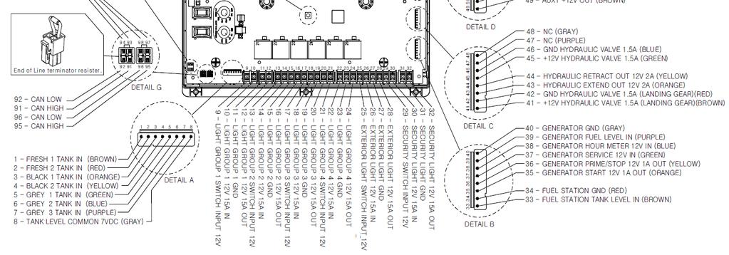
4 BCM Pin Values Tanks Interior Lighting I/O Exterior Lighting I/O Pin Name BCM Function Note A DMM 1 Fresh 1 Tank In Input from Sending Unit 2 Fresh 2 Tank In Input from Sending Unit 0-.74V = EMPTY ( ) 3 Black 1 Tank In Input from Sending Unit V = 1/3 ( ) 4 Black 2 Tank In Input from Sending Unit V = 2/3 ( ) 5 Gray 1 Tank In Input from Sending Unit 3.6V = FULL ( ) 6 Gray 2 Tank In Input from Sending Unit MEASURE FROM PIN 11 TO EACH 7 Gray 3 Tank In Input from Sending Unit INPUT 8 Tank Common 7 Output to all Tanks 7 9 Light Group 1 12V Switch IN Input From External Momentary Switch Light Group 1 12V 15A IN Input From Main Breaker Box Light Group 1 Ground Common Ground GND 12 Light Group 1 12V 15A Out Output 12 to LG Light Group 2 12V Switch In Input From External Momentary Switch Light Group 2 12V 15A In Input From Main Breaker Box Light Group 2 Ground Common Ground GND 16 Light Group 2 12V 15A Out Output 12 to LG Light Group 3 12V Switch In Input From external Momentary Switch Light Group 3 12V 15A In Input From Main Breaker Box 12 15A 19 Light Group 3 Ground Common Ground GND 20 Light Group 3 12V 15A Out Output 12V to LG Light Group 4 12V Switch In Input From External Momentary Switch Light Group 4 12V 15A In Input From Main Breaker Box Light Group 4 Ground Common Ground GND 24 Light Group 4 12V 15A Out Output to LG Exterior Light 12V Switch In Input From External Momentary Switch Exterior Light 12V 15A In Input From Main Breaker Box Exterior Light Ground Common Ground GND 28 Exterior Light 12V 15A Out Output 12V to Exterior Light 12
5 BCM Pin Values (Cont.) Security Light I/O Fuel Station Generator HYD Landing Gear Pin Name BCM Function Note A DMM 29 Security Light 12V Switch In Input From External Momentary Switch Security Light 12V 15A IN Input From Main Breaker Box Security Light Ground Common Ground GND 32 Security Light 12V 15A Out Output 12V to Security Light Fuel Station Tank Level In Input from Sending Unit 33 OHM= FULL ( ), Ω 49 OHM= 2/3 ( ) 127 OHM= 1/3 ( ), 240 OHM= Empty ( ) 34 Fuel Station GND GND Pass Through GND Connection 35 Generator Start Ground Out Output Ground until button GND is released 36 Generator Prime/Stop Ground Output Ground GND Out 37 Generator Service 12V In 12V Pulse Input Generator Hour Meter 12V In 12V Input triggers timer to 12 start 39 Generator Fuel Level In Input from Sending Unit 33 OHM= FULL ( ), Ω 49 OHM= 2/3 ( ) 127 OHM= 1/3 ( ), 240 OHM= Empty ( ) 40 Generator Ground Common Ground GND V Hydraulic Valve 1.5A Output 12V 1.5A 12 (Landing Gear) 42 Ground Hydraulic Valve Common Ground GND (Landing Gear) 43 Hydraulic Extend Out 12V 2A Output 12V for Extend 2A GND Valve 44 Hydraulic Retract Out 12V 2A Output 12V for Retract 2A GND Valve
6 BCM Pin Values (Cont.) HYD Slides AUX Triggers Alarm Inputs Travel Lockout Water Heater Pin Name BCM Function Note A DMM 45 12V Hydraulic Valve 1.5A Output 12V 1.5A 12 (Slide Solenoid) 46 Ground Hydraulic Valve Common Ground GND (Slide Solenoid) 47 No Connection 48 No Connection 49 Trigger 1 12V Out Programmable 12V Latch or 12 Momentary 50 Trigger 2 12V Out Programmable 12V Latch or 12 Momentary 1A 51 Trigger 3 12V Out Programmable 12V Latch or 12 Momentary 52 Trigger 4 12V Out Programmable 12V Latch or 12 Momentary 53 Alarm 1 12V In Programmable 12V On or 12 Off Input 54 Alarm 2 12V In Programmable 12V On or 12 Off Input 1A 55 Alarm 3 12V In Programmable 12V On or 12 Off Input 56 Alarm 4 12V In Programmable 12V On or 12 Off Input 57 Travel Lockout 12V In 12V Input from Tow Vehicle Locks out all motor functions 12 Brake signal when signal is present 58 Water Heater Ground Common Ground GND 59 Water Heater Gas 12V 1A Out 12V Output to Gas Ignitor Water Heater Electric 12V 1A 12V Output to Electric 1A 12 Out Ignitor 61 Water Heater 12V Fault In Receive 12V Fault Signal 12
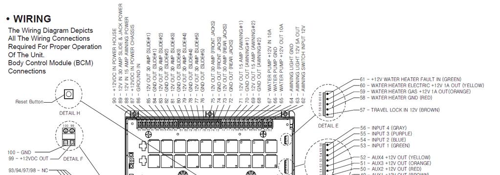
7 BCM Pin Values (Cont.) Awning Light Water Pump Awning Motors Jacks Electric Slide Motors Power Pin Name BCM Function Note A DMM 62 Awning Light 12V Switch In Input From External Momentary Switch Awning Light 12V 3A Out Output 12V to Awning Light Power from Awning 15A Input 3A Awning Light Ground Common Ground GND 65 Water Pump 12V 10A Out Output 12V to Water Pump 10A Water Pump Ground Common Ground GND 67 Water Pump 12V 15A In Input From Main Breaker Box 10A Awning 2 Retract Out Output Reversing Polarity DC Motor 12V/GND 69 Awning 2 Extend Out Output Reversing Polarity DC Motor 12V/GND 15A 70 Awning 1 Retract Out Output Reversing Polarity DC Motor 12V/GND 71 Awning 1 Extend Out Output Reversing Polarity DC Motor 12V/GND 72 Rear Jack Retract Out Output Reversing Polarity DC Motor 12V/GND 73 Rear Jack Extend Out Output Reversing Polarity DC Motor 12V/GND 74 Front Jack Retract Out Output Reversing Polarity DC Motor 12V/GND 75 Front Jack Extend Out Output Reversing Polarity DC Motor 12V/GND 76 Slide 5 Retract Out Output Reversing Polarity DC Motor 12V/GND 77 Slide 5 Extend Out Output Reversing Polarity DC Motor 12V/GND 78 Slide 4 Retract Out Output Reversing Polarity DC Motor 30A 12V/GND 79 Slide 4 Extend Out Output Reversing Polarity DC Motor 12V/GND 80 Slide 3 Retract Out Output Reversing Polarity DC Motor 12V/GND 81 Slide 3 Extend Out Output Reversing Polarity DC Motor 12V/GND 82 Slide 2 Retract Out Output Reversing Polarity DC Motor 12V/GND 83 Slide 2 Extend Out Output Reversing Polarity DC Motor 12V/GND 84 Slide 1 Retract Out Output Reversing Polarity DC Motor 12V/GND 85 Slide 1 Extend Out Output Reversing Polarity DC Motor 12V/GND 86 Ground In Input From Chassis Ground GND 87 Power Chassis 12V In Input From Chassis Battery (Motorized) Awning Power 12V 15A In Input From Main Breaker Box 15A Electric Slide/Jack Power 12V Input From 12V 30A mini reset fuse 30A 12 30A IN 90 Main Power 12V 15A In Input From Main Breaker Box 15A 12


 connection.")
 will be mounted in an \"all access\" area near the entrance. On the DC, press and release the Power button (the left button) to wake up the DC.")
8 NCSP3 Functionality Test The Body Control Module (BCM) should be wired correctly, without loose connections, and connected to 12 at pin 90. A RED LED will indicate that the BCM is receiving 12. The 2 toggle switches on the BCM correspond to the 2 dials underneath them. (In the event where communication between the Display Commander (DC) and BCM is non-functioning, these switches will enable "manual" functions of the selected devices) The Left switch and knob are used for Electric Awnings and Jacks. (Hydraulic Jacks are manually controlled at the Hydraulic Pump. See the Hydraulic Pump Manual Override in the RV owner's manual), and the Right switch and knob are used for Electric Slides 1-5. The BCM and DC communicate with each other through an RV-C (CAN BUS) connection. This RV-C communication also allows the DC to connect to a third party AC translator module (gateway) so that you can perform the HVAC functions from the DC. The Display Commander (DC) will be mounted in an "all access" area near the entrance. On the DC, press and release the Power button (the left button) to wake up the DC. After a moment, the Passcode Screen will appear. Enter your Passcode. If this is the first time the DC has been powered on, an End User License Agreement (EULA) screen will appear. Upon accepting the EULA, an Enter New Passcode screen will appear. Enter your new passcode and confirm. The DC will now bring up the Home Screen If the Floor Plan has been loaded, all of the devices should be listed with corresponding actitation buttons

9 Go through all the functions and make sure they are operating properly. All the functions should be smooth and instantaneous. Ensure all the Home Page Hot keys actuate/turn on the corresponding functions. Cycle the Generator. When the Generator is being cycled for the first time (or if it has been a while since it has been used), it will need to be primed. Hold the Prime button down to 2-5 seconds, then press and hold the Start button down until the generator starts. HVAC Testing When testing the HVAC (Climate Function), make sure each Zone is displaying a room (Zone) temperature. Use the Mode button to cycle through Fan, Cool, Heat and Auto modes. (Heat and Auto modes availability depend on the floor plan.) in-command is also equipped with an Auto Gen start. Press the Manual button to switch to Auto to activate the Auto Gen start function. If the battery voltage is less than 11.8V for 3 minutes, the system will start the generator. If the generator is started, the generator will run for 60 Minutes. Also, the system will attempt to start the generator 3 times. If the generator fails to start after the 3 rd attempt, the system will turn off the Auto feature and display a Check Generator Fault Message.


10 Use the Set temperature up and down arrows to set the desired temperature. The Set temperature can be adjusted between 55 to 90F. Please review the NCSP3 User Manual for further HVAC operational instructions. You can scan the QR code shown below or use the following link:
11 Troubleshooting HVAC (Dometic Systems) If the room temp reads 100F, remove the room sensor cover and pull the room sensor out of the holding clip. The temp should read normally. Adjust the holding clip down on the room sensor so that it is not pinching it. (RVP Systems) If the room temp reads 111F, the room sensor was connected to the cool shed connections on the RVP control box. Swap the wires between the cool shed and room sensor pins. The room temp should start reading correctly without a reset. (Both Systems)If no HVAC function, check to see if the room (zone) temp is blank. If it is, make sure the RV-C cables are connected to the gateways and make sure there is an EOL (End of Line) terminator resistor at the last gateway in the line. Make sure the address on the gateway is correct. If that is correct, redo the power, ground and communication wires between the gateway and control box. Verify the gateway has proper +12. (Dometic)If there are multiple rapid clinking sounds when operating the furnace function, the gateway has old software and needs to be swapped out. (Dometic)If a zone will not change functions (i.e. stuck on furnace mode), try adjusting the fan speed. Most likely it will show Auto, try and get it to either low or high. This indicates the gateway is in a locked state. If you can get the fan mode to change, you should then be able to change the zone function to off. Once it stays in off mode, power cycling the system. If changing an HVAC function in a Zone, and the function changes in a different zone, the dip switches are not set correctly. The front AC is Zone 1, middle is Zone 2 and rear is Zone 3. (RV-C) Communication issues Make sure the CAN-Low does not have a short to +12V. Make sure the CAN-High does not have a short to ground. Make sure there is not a short between CAN-Low and CAN-High. Check RV-C plugs and pins to make sure there is not a loose connection. Try and power cycle all the components. Make sure the RV-C connector is pinned correctly. Try a different RV-C cable. Press the reset button on the BCM. If the generator or auxiliary fuel I/O s from the BCM are connected directly to +12, all low current functions on the BCM will not operate properly. I.E: The RV-C will not communicate properly and the water tanks will not read correctly. No BCM Power Check if the Red Power indicator is lit. Press the reset button on the BCM. Verify 12V on Pin 90 and Ground on pin 86. Check Fuse in Main Breaker Box. Cycle RV Power at the Main Breaker Box. No DC Power Cycle power with the Power Button. (Press and hold the power button for 5 seconds.) Verify 12V and Ground at the back of the DC. Verify no blown fuses in the Main Breaker Box.
12 Slide Rooms do not move Verify 12V on pin 89. If the Battery Disconnect switch is off, turn it on. (Some models pull the slide power through the battery disconnect.) Awnings do not move Verify 12V on pin 88. Check fuse in Main Breaker Box. Water Tank Make sure the common pin (Pin 8) is outputting +7. If no voltage, disconnect the tank harness and test the pin on the BCM. If there is voltage now, that indicates the common wire has a short to ground. If one of the tanks is reading, but another tank does not read, remove the wires from the bell caps and swap the tank wires. If the opposite tank now reads, that indicates the BCM is fine and there is an issue in the tank line. The tank level voltages are as follows: o 1/3:.75 to 1.74 o 2/3: 1.75 to 3.59 o 3/3: 3.6 and above Main power Pin 90. Then press the Gen Start button on the DC. The voltage reading on the DMM will jump to full voltage if the circuit is working correctly. If the generator prime/stop function does not work: o Make sure the Gen Prime/Stop wire (Pin 36, yellow) is making a good connection. o To check the signal output, connect the negative lead from a DMM (volt multi-meter) to Pin 36 and the positive lead to Main power Pin 90. Then press the Gen Start button on the DC. The voltage reading on the DMM will jump to full voltage if the circuit is working correctly. The generator is running, but the start button has not switched to stop and the hour meter is not counting: o Make sure the Gen Hour Meter wire (Pin 38, blue) is making a good connection. o If the generator is running, the generator should be outputting a 12V signal to the Hour Meter input Pin 38 on the BCM. If no voltage present, check signal from generator. Note: The DC will display generator fault codes provided by the generator. If you get a generator fault popup (like Low Oil ), consult the generator owner s manual for further troubleshooting on the generator. Generator If the generator will not start: o Make sure the Gen Start wire (Pin 35, orange) is making a good connection. o To check the signal output, connect the negative lead from a DMM (volt multi-meter) to Pin 35 and the positive lead to For additional troubleshooting, call ASA Electronics Technical Support at , info@asaelectronics.com or visit our in-command support page at
Troubleshooting Guide
 Troubleshooting Guide BCM Pin Values Tanks Lighting I/O s Travel Lockout Water Heater Water Pump Pin Name BCM Function Note A DMM 1 Fresh 1Tank In Input from Sending Unit 2 Fresh 2 Tank In Input from
JRVCS2 TROUBLESHOOTING
 JRVCS2 TROUBLESHOOTING This guide is made to ease troubleshooting the in-command system. It will cover the wiring code and where those wires are connected to the Body Control Module (BCM) and Display Commander
JRVCS105 TROUBLESHOOTING GUIDE
 JRVCS105 TROUBLESHOOTING GUIDE This guide is made to ease troubleshooting the in-command system. It will cover the wiring code and where those wires are connected to the Body Control Module (BCM) and Display
Auto-Level Troubleshooting (Old Platform) Electronic Control- Prior to 2009, Pressure Switch Control panel #s 2057, 2058, 2795, 2795B
 Electronic Control- Prior to 2009, Pressure Switch Control panel #s 2057, 2058, 2795, 2795B") Auto-Level Troubleshooting (Old Platform) Electronic Control- Prior to 2009, Pressure Switch Control panel #s 2057, 2058, 2795, 2795B This guide addresses the troubleshooting of electronic controls used
Auto-Level Troubleshooting (Old Platform) Electronic Control- Prior to 2009, Pressure Switch Control panel #s 2057, 2058, 2795, 2795B This guide addresses the troubleshooting of electronic controls used
e-ask electronic Access Security Keyless-entry
 e-ask electronic Access Security Keyless-entry Multiplex System Multiplex System Installation & Instructions (UM15 ~ 22272-03) Table of Contents Introduction... 1 Standard e-fob Operation and Features...
SECOND GENERATION Use this guide with unit serial number prefix beginning with BWF using Terra Power separator.
 Technical Information and Diagnostic Guide for SECOND GENERATION Use this guide with unit serial number prefix beginning with BWF using Terra Power separator. This guide will assist you in becoming more
6R / 5-BUTTON SERIES VEHICLE SECURITY SYSTEM
 6R / 5-BUTTON SERIES VEHICLE SECURITY SYSTEM Button 1 Button 2 Button 5 Button 3 Button 4 Standard Features: Two 5-Button Remote Transmitters Status indicator (LED) Valet / override switch Multi-tone siren
Wiring diagrams on page 29 are for reference only. For detailed vehicle wiring refer to Navistar documents.
 1 10/2014 REV 7 !!Attention!! Before performing diagnostics: Wiring diagrams on page 29 are for reference only. For detailed vehicle wiring refer to Navistar documents. Check for Fault Codes using the
SERIES 700/700E FACTORY KEYLESS UPGRADE INSTALLATION MANUAL
 SERIES 700/700E FACTORY KEYLESS UPGRADE INSTALLATION MANUAL Items Supplied with the System: Installation Instructions: Main unit 1. Mounting the module: Plug In LED Mount the module in a suitable location
SERVICE MANUAL. Kysor Instrumentation Troubleshooting Guide
 Kysor Instrumentation Troubleshooting Guide Troubleshooting Emergency One Commercial System The Medallion II instrumentation system is a Microprocessor based system utilizing both Sensor and Data bus information
INSTALLATION GUIDE Table of Contents
 CT-3100 Automatic transmission remote engine starter systems. What s included..2 INSTALLATION GUIDE Table of Contents Door lock toggle mode..... 4 Notice...2 Installation points to remember. 2 Features..2
MEGA 462 REMOTE CONTROL AUTO ALARM SYSTEM INSTALLATION & OPERATION INSTRUCTIONS WIRING DIAGRAM. White. H1 5 Pin White. H6 2 Pin White.
 MEGA 462 REMOTE CONTROL AUTO ALARM SYSTEM INSTALLATION & OPERATION INSTRUCTIONS WIRING DIAGRAM H7/1 Green : (-) 200mA Pulse H7 3 Pin H7/3 Blue : (-) 200mA Unlock White LED Indicator Valet Switch H6 2 Pin
Technical Information and Diagnostic Guide RestStar Use this guide with 5700XE RestStar Unit. Western Star 5700XE.
 Western Star 5700XE RestStar 4 10-2017 1 Technical Information and Diagnostic Guide RestStar Use this guide with 5700XE RestStar Unit 2390 Blackhawk Road P.O. Box 6007 Rockford, IL 61125 nitesystem.com
VC-4820 Programmable DC-DC Converter with Battery Charger function USER'S MANUAL
 1. INTRODUCTION VC-4820 Programmable DC-DC Converter with Battery Charger function USER'S MANUAL This MCU controlled Step Down DC-DC Converter has a digitally adjustable output in 0.2V increments. This
Technical Information and Diagnostic Guide
 Technical Information and Diagnostic Guide This guide will assist you in becoming more familiar with the working components of the NITE System and the proper steps and procedures to completely diagnose
INSTALLATION MANUAL. Model: PLUS For Technical Assistance, please call (800) , or visit
 , or visit") R Vehicle Security INSTALLATION MANUAL Model: PLUS-4700 This device complies with part 15 of the FCC rules. Operation is subject to the following two conditions: (1) This device may not cause harmful interference;
R Vehicle Security INSTALLATION MANUAL Model: PLUS-4700 This device complies with part 15 of the FCC rules. Operation is subject to the following two conditions: (1) This device may not cause harmful interference;
Service Manual for Battery Control Center
 Service Manual for Battery Control Center P/N 82 E0071 00 (Ref. 81 1317) June, 1999 Battery Control Box Operation Charging Circuit This function charges the coach battery from the engine alternator while
NIDAC EMC Communicating Motor
 NIDAC EMC Communicating Motor IFC 12 V Variable Speed Connection Variable Speed Connection 12 V = + 12 Volt DC RX = Motor to Furnace Control Data TX = Furnace to Motor Control Data GND = 12 Volt DC Ground
Vehicle Security System
 Installation Instructions Vehicle Security System PROFESSIONAL INSTALLATION STRONGLY RECOMMENDED Installation Precautions: Roll down window to avoid locking keys in vehicle during installation Avoid mounting
ITCEMS950 Idle Timer Controller - Engine Monitor Shutdown Isuzu NPR 6.0L Gasoline Engine
 Introduction An ISO 9001:2008 Registered Company ITCEMS950 Idle Timer Controller - Engine Monitor Shutdown 2014-2016 Isuzu NPR 6.0L Gasoline Engine Contact InterMotive for additional vehicle applications
Modulating Furnace Information. Warning on Meter Setting - Read First!
 Modulating Furnace Information Pressure Transducer Pressure DC Volts 0.00" 0.25 0.20" 0.63 0.25" 0.72 0.30" 0.82 0.35" 0.91 0.40" 1.00 0.45" 1.09 0.50" 1.19 0.55" 1.28 0.60" 1.38 0.65" 1.47 0.70" 1.56
OPERATOR S MANUAL HWH COMPUTER-CONTROLLED 2000 SERIES LEVELING SYSTEM. FEATURING: Single Step Touch Panel Control Air Leveling
 OPERATOR S MANUAL HWH COMPUTER-CONTROLLED 000 SERIES LEVELING SYSTEM R HWH CORPORATION R FEATURING: Single Step Touch Panel Control Air Leveling HWH COMPUTERIZED LEVELING LEVEL AIR EXCESS SLOPE MODE DUMP
Grout Pump Automatic & Manual Troubleshooting Gas Wiring Diagram
 Grout Pump Automatic & Manual Troubleshooting 40-500 Gas Wiring Diagram Turn engine off and relieve hydraulic pressure and grout pressure before troubleshooting. Note: Typically there is a wiring diagram
Installation & Service Manual
 Installation & Service Manual for M² Sync Slideout Control Box #1510000122 CONTENTS Introduction Installation Installation Problems Program Mode Operation Mode Preventative Maintenance Fault Diagnostics
Turny Evo. Autoadapt. Seat lift. Installation manual
 Turny Evo Autoadapt Seat lift EN Installation manual Getting seated Turny Evo Thank you for choosing a Turny Evo from Autoadapt! The manual that follows is an integral, important part of the product,
Do isolate the power supply from other high power systems such as Stereos and Alarms
 Thank you for purchasing a Smart Ride Air Management System, AIRBAGIT.COM s premier flagship product. This system will meet all of your custom and utility needs and will provide you years of trouble free
Third Generation NITE Phoenix
 Technical Information and Diagnostic Guide for Third Generation NITE Phoenix Use this guide with unit serial number prefix beginning with BYC, CAI built after 2-10-2012 and CCA, CDJ, CIA units after 6/25/2012
BIGLA30-T/BIELA14-T Event Codes Quick Reference EXPLANATION CORRECTIVE ACTION PARTS TO CARRY ON SERVICE CALL
 E13 TEMPERATURE PROBE FAILURE E16 HIGH LIMIT 1 EXCEEDED A. TEMP Probe reading out of range. B. Bad Connection. C. Problem with the temperatur e measuring circuitry including the probe. High limit temperature
Battery Control Center - Diesel
 Service Manual CAUTION: All servicing of the Battery Control Center should be done only by a qualified Service Technician. Inadvertent shorts inside the Battery Control Center could result in severe damage
Gateway 505/605 Symptom Flow Chart Lift Interlock
 An ISO 9001:2008 Registered Company Gateway 505/605 Symptom Flow Chart Lift Interlock Begin diagnosis by performing the system post installation instructions notating system operation while doing checks.
Troubleshooting Guide
 Troubleshooting Guide P/N 0153180 July 1999 P.O. Box 1160 St. Joseph, MO 64502-1160 1-800-255-0317 Fax: 816-360-9379 www.snorkelusa.com GENERAL INFORMATION This manual contains procedures for locating
INSTALLATION MANUAL. Middle. Def tank. Standard. Middle. Standard. Def tank WARNING. Level of Difficulty CAUTION. Parts List.
 INSTALLATION MANUAL 3025101 Level of Difficulty Moderate This is the second first of two of two manuals required to complete this installation. The first second manual manual is is included with with your
INSTALLATION MANUAL. Remote Mobile Security System. Model: PL30
 Remote Mobile Security System INSTALLATION MANUAL Model: PL30 Copyright 1998 Magnadyne Corporation For Technical Assistance (800) 638-3600 For Fax on Demand Technical Assistance (800) 994-9977 (Must be
EC200 ELECTRONIC CONTROL SYSTEM
 1 INTRODUCING THE EC200 ELECTRONIC CONTROL SYSTEM With the use of new technology and an innovative approach to user interfacing, the EC200 Power Control System provides a complete control solution for
Vehicle Security System
 Installation Instructions Vehicle Security System PROFESSIONAL INSTALLATION STRONGLY RECOMMENDED Installation Precautions: Roll down window to avoid locking keys in vehicle during installation Avoid mounting
C-PIM701 (Police Interface Module) 2018 Dodge Charger Pursuit
 2018 Dodge Charger Pursuit") An ISO 9001:2008 Registered Company C-PIM701 (Police Interface Module) 2018 Dodge Charger Pursuit Introduction The Police Interface Module is intended to provide Dodge Chargers with multiple desired functions
An ISO 9001:2008 Registered Company C-PIM701 (Police Interface Module) 2018 Dodge Charger Pursuit Introduction The Police Interface Module is intended to provide Dodge Chargers with multiple desired functions
CS-865RKE Series II REMOTE KEYLESS ENTRY SYSTEM
 INTRODUCTION: CS-865RKE Series II REMOTE KEYLESS ENTRY SYSTEM INSTALLATION & OPERATING INSTRUCTIONS CONGRATULATIONS on your choice of a Remote Keyless Entry System by Crimestopper Security Products Inc.
GCU-10. Automatic Engine Control Unit Operators Manual
 GCU-10 Automatic Engine Control Unit Operators Manual KUTAI ELECTRONICS INDUSTRY CO., LTD. TEL : +886-7-8121771 FAX : +886-7-8121775 Website : www.kutai.com.tw Headquarters : No.3, Lane 201, Chien Fu St.,
Factory Packaged Controls. OE (AAON Part No. V12090) MODGAS-X Controller Field Technical Guide
 MODGAS-X Controller Field Technical Guide") Factory Packaged Controls OE377-26-00058 (AAON Part No. V12090) MODGAS-X Controller Table of Contents GENERAL INFORMATION... 3 Overview...3 Features...3 INSTALLATION & WIRING... 4 Supply Air Temperature
Factory Packaged Controls OE377-26-00058 (AAON Part No. V12090) MODGAS-X Controller Table of Contents GENERAL INFORMATION... 3 Overview...3 Features...3 INSTALLATION & WIRING... 4 Supply Air Temperature
Inspection Points - Motor Homes
 Inspection Points - Motor Homes We at RVIS, LLC appreciate your business and look forward to providing you with the professional RV inspection you deserve. So that we may provide you with a thorough inspection,
Northwest RV Supply Manual Compliments of Printed From TROUBLESHOOTING
 TROUBLESHOOTING for the 5 BUTTON 3109228.001 COMFORT CONTROL CENTER SYSTEM INTRODUCTION The Comfort Control Center control system can be used to operate the following Duo-Therm Units: Roof Top Air Conditioners
702 AUTOMATIC START MODULE OPERATING INSTRUCTIONS
 702 AUTOMATIC START MODULE OPERATING INSTRUCTIONS > TABLE OF CONTENTS 1 DESCRIPTION OF OPERATION... 4 1.1 MANUAL MODE OPERATION... 4 1.2 AUTOMATIC MODE OF OPERATION...
MEGA WAY LCD 4-CHANNEL CAR ALARM SECURITY SYSTEM. Installation Manual MEGATRONIX CALIFORNIA, USA MEGA 2500 INSTALL 1
 MEGA 2500 2-WAY LCD 4-CHANNEL CAR ALARM SECURITY SYSTEM Installation Manual MEGATRONI CALIFORNIA, USA MEGA 2500 INSTALL 1 MEGA 2500 INSTALL 2 INSTALLATION DIAGRAM H8: 10 Pin White Mini Connector H8 10
Model 2300JL Installation Guide
 Model 2300JL Installation Guide POWER ACCESS CORPORATION 4 HERSHEY DRIVE, DOCK 4 ANSONIA, CT 06401 800-344-0088 WEBSITE: www.power-access.com EMAIL: salesinfo@power-access.com 1 STANDARD PARTS MODEL 2300JL
Idle Timer Controller - ITC Freightliner MT45 Contact InterMotive for additional vehicle applications
 An ISO 9001:2008 Registered Company System Operation Idle Timer Controller - ITC805 2013-2018 Freightliner MT45 Contact InterMotive for additional vehicle applications The ITC805 system shuts down idling
GTWY515, GTWY516* Fast Idle, Shift Interlock, I/O Ford Transit Introduction
 An ISO 9001:2015 Registered Company GTWY515, GTWY516* Fast Idle, Shift Interlock, I/O 2015-2019 Ford Transit Introduction The Gateway 515 and 516 are wheelchair lift safety interlocks which allows lift
Service/Installation Manual Full Wall Slide Systems CONTENTS. 82-S0379 Rev 3. Page. Before you operate the slide system 2
 Service/Installation Manual Full Wall Slide Systems CONTENTS Page Before you operate the slide system Operating instructions Preventive maintenance Manually overriding your slide system 0" Stroke system
SYMBOL LEGEND DANGER WARNING NOTE THIS INDICATES DANGER TO THE LIFE AND HEALTH OF THE USER IS APPROPRIATE PRECAUTIONS ARE NOT TAKEN
 SYMBOL LEGEND DANGER THIS INDICATES DANGER TO THE LIFE AND HEALTH OF THE USER IS APPROPRIATE PRECAUTIONS ARE NOT TAKEN WARNING THIS WARNS THAT MATERIALS MAY BE DAMAGED IF APPROPRIATE PRECAUTIONS ARE NOT
INSTALLATION MANUAL. Remote Mobile Security System. Model: PL50
 Remote Mobile Security System INSTALLATION MANUAL Model: PL50 Copyright 2000 Magnadyne Corporation For Technical Assistance (800) 638-3600 For Fax on Demand Technical Assistance (800) 994-9977 (Must be
INSTALLATION MANUAL. Model: PLUS Vehicle Security
 R Vehicle Security INSTALLATION MANUAL Model: PLUS-5000 Copyright 1999 Magnadyne Corporation For Technical Assistance (800) 638-3600 For Fax on Demand Technical Assistance (800) 994-9977 (Must be a Registered
DTC B0228, B0413, B0423, Or B3779
 2007 Chevrolet Silverado 1500 : Heating, Ventilation, & Air Conditioning > HVAC Systems - Manual > Diagnostic Information And Procedures > DTC B0228, B0413, B0423, Or B3779 DTC B0228, B0413, B0423, Or
Elite Power Solutions Automatic Battery Control (ABC) Operation Manual
 Operation Manual") Elite Power Solutions Automatic Battery Control (ABC) Operation Manual Elite Power Solutions 335 E Warner Rd. STE 3 Chandler, AZ 85225 www.elitepowersolutions.com ABC Operation Manual Page 1 Table of Contents
Elite Power Solutions Automatic Battery Control (ABC) Operation Manual Elite Power Solutions 335 E Warner Rd. STE 3 Chandler, AZ 85225 www.elitepowersolutions.com ABC Operation Manual Page 1 Table of Contents
Installation and Service Manual M² Sync Room Slideout System without Room Lock Connectors on Control Box
 Installation & Service Manual M² Sync Room Slideout System w/o Room Locks: for Slideout Control Box# 1510000143 and 1510000198 Figure 1 01/13 Power Gear #3010002088 Rev. 0C Installation and Service Manual
An ISO 9001:2008 Registered Company
 Introduction An ISO 9001:2008 Registered Company GTWY506 Fast Idle, Shift Interlock, I/O 2011-2016 Ford F250-F550 2017 Ford F250-F550 (Uses the Ford 24-Pin Data Link Harness) 2016-2017 Ford F650/750* *Transmission
Electric Stabilizer Jack
 Electric Stabilizer Jack OWNER'S MANUAL Rev: 10.09.2017 Page 1 Electric Stabilizer Jack Owners Manual TABLE OF CONTENTS System 2 System Description 3 Operation 3 Extending Stabilizer Jack 3 Retracting
OnCommand Troubleshooting Guide Hayward Industries
 OnCommand Troubleshooting Guide 2010 Hayward Industries Table of Contents Safety Precautions Page 1 Overview Pages 2-5 Software Troubleshooting Page 6 Local Display Pages 7-8 Relays Pages 9-10 Heaters
WARRANTY WILL BE VOID If These Steps are Not Performed Before Installing The Control STEPS TO PERFORM BEFORE CONTROL INSTALLATION
 Curtis 1268-5411 This sheet is provided to aid in the installation of your remanufactured CURTIS controller. Upon installation, you may encounter problems that may, or may not, be due to a faulty controller.
GTWY605 Fast Idle, Shift Interlock, I/O Chevy 610 Van - 6.0L and 6.6L Engines Contact InterMotive for additional vehicle applications.
 An ISO 9001:2008 Registered Company GTWY605 Fast Idle, Shift Interlock, I/O 2009-2017 Chevy 610 Van - 6.0L and 6.6L Engines Contact InterMotive for additional vehicle applications. Introduction The Gateway
2 Way Security and Keyless Entry Installation Guide ca 1553
 PROFESSIONAL SERIES 2 Way Security and Keyless Entry Installation Guide ca 1553 2012 Audiovox Electronics Corporation. All rights reserved. 1 Table of Contents Before You Begin... 3 Wire Connection Guide...
TECHNICAL SERVICE DEPARTMENT Technical Service Bulletin LowNOx Commercial Gas Electronic Spark Ignition Sequence
 The Universal TM gas LowNOx series water heaters contain an electronic spark ignition system. The heater is connected to a 120VAC power source required by the transformer. The transformer steps down the
ADD-ON REMOTE STARTER TO AFTERMARKET SYSTEM
 MEGATRONIX RS 110 ADD-ON REMOTE STARTER TO AFTERMARKET SYSTEM Installation and Operation Manual MEGATRONIX CHATSWORTH, CA U.S.A. RS110 ADD-ON REMOTE CAR STARTER For Vehicles Equipped With Automatic Transmission
VEHICLE SECURITY SYSTEM INSTALLATION MANUAL
 VEHICLE SECURITY SYSTEM WITH REMOTE START & NETWORK INTERFACE INSTALLATION MANUAL BEFORE INSTALLING THIS PRODUCT PLEASE READ THIS INSTALLATION MANUAL THOROUGHLY!! Before You Begin This system is intended
INTRODUCTION PRELIMINARY DIAGNOSIS
 NO: 21-11-98 SUBJECT: Transmission Simulator Diagnostic Tool DATE: Dec. 11, 1998 NOTE: THIS INFORMATION APPLIES TO VEHICLES EQUIPPED WITH A 45RFE TRANSMISSION. DISCUSSION: A new transmission simulator
EXTENDED INSTALL GUIDE Revision /2015 FW 51+
 AUTOMATIC/MANUAL TRANSMISSION REMOTE STARTER EXTENDED INSTALL GUIDE Revision 4.02-08/2015 FW 51+ 12V CONSTANT IN RED 1 ( + ) 500mA 12V TO STARTER PURPLE 2 ( + ) 500mA 12V TO IGNITION PINK 3 SYSTEM GROUND
Model 2300DL Installation Guide
 Model 2300DL Installation Guide POWER ACCESS CORPORATION 4 HERSHEY DRIVE, DOCK 4 ANSONIA, CT 06401 800-344-0088 WEBSITE: www.power-access.com EMAIL: salesinfo@power-access.com 1 STANDARD PARTS MODEL 2300DL
USERS GUIDE LO-21U LOCKOUT RELAY
 USERS GUIDE LO-21U LOCKOUT RELAY PRODUCT DESCRIPTION The LO-21U (PN: 10LO21U) is a micro-processed lock out module designed to operate on swing door applications with BEA s Bodyguard or DK-12 overhead
MM1 Installation Instructions
 MM1 Installation Instructions PROFESSIONAL INSTALLATION STRONGLY RECOMMENDED Installation Precautions: Roll down window to avoid locking keys in vehicle during installation Avoid mounting components or
CONTROL BOX. Wiring the control box into the vehicle. +12V
 CONTROL BOX Once the display panel is in place, mount the control box within the connecting cable's distance (approximately 3 feet) and secure to the underside of the dashboard. This case does not have
SUN ELECTRONIC SYSTEMS EC1X HEAT/COOL TROUBLESHOOTING GUIDE
 SUN ELECTRONIC SYSTEMS EC1X HEAT/COOL TROUBLESHOOTING GUIDE 062013 COVERS MODELS EC1x SUN ELECTRONIC SYSTEMS, INC. Tel: 321-383-9400 1845 Shepard Drive Fax: 321-383-9412 Titusville Florida Email:info@sunelectronics.com
PF3100 TROUBLESHOOTING SOLUTIONS TO COMMON PROBLEMS. v1.1 Revised Nov 29, 2016
 PF3100 TROUBLESHOOTING SOLUTIONS TO COMMON PROBLEMS v1.1 Revised Table of Contents 1 Common Alarms and Warnings... 1 2 Common Issues... 6 2.1 Communication problems... 6 2.1.1 Controller communication
GTWY505 Fast Idle, Shift Interlock, I/O Ford E-Series
 An ISO 9001:2008 Registered Company GTWY505 Fast Idle, Shift Interlock, I/O 2009-2018 Ford E-Series Introduction The Gateway 505 is a wheelchair lift safety interlock which will only work with the ignition
PROFESSIONAL INSTALLATION STRONGLY RECOMMENDED
 100755-2 Installation Instructions PC 4200 PROFESSIONAL INSTALLATION STRONGLY RECOMMENDED Installation Precautions: Roll down window to avoid locking keys in vehicle during installation Avoid mounting
An ISO 9001:2015 Registered Company
 Introduction An ISO 9001:2015 Registered Company HL550-B Fast Idle, Lift Interlock 2011-2016 Ford F250-F550 2017-2019 Ford F250-F550 (B-HL550*) 2016-2017 Ford F650/750** *Uses the Ford 24-Pin Data Link
ECO3-601/602 EcoStar III * Chevy Express/GMC Savana Contact Intermotive for additional vehicle applications
 An ISO 9001:2015 Registered Company ECO3-601/602 EcoStar III 2009-2019* Chevy Express/GMC Savana Contact Intermotive for additional vehicle applications * In 2017-2018, the ignition switches on Chevy Express
AIRSTREAM - BATTERY CONTROL CENTER - Diesel
 P/N 00-00755-000 CAUTION: The Battery Control Center is a centralized power switching, fusing, and distribution center. Power from both the chassis and coach batteries is fed into the box. The full power
ALARM UPGRADE FOR FACTORY REMOTE KEYLESS ENTRY SYSTEM INSTALLATION PRECAUTIONS & WARNINGS
 CS-882 OEM ALARM UPGRADE FOR FACTORY REMOTE KEYLESS ENTRY SYSTEM INSTALLATI PRECAUTIS & WARNINGS NOTE: This system does not improve or affect the range of the factory remote keyless entry transmitters.
EXCELSIOR-HENDERSON MOTORCYCLE MANUFACTURING COMPANY 805 HANLON DRIVE BELLE PLAINE, MINNESOTA TELE: /FAX:
 All text, photographs, and illustrations in this handbook are based on the most current product information available at the time of publication. Product improvements or other changes may result in differences
PIM701 (Police Interface Module) Dodge Charger Pursuit
 Dodge Charger Pursuit") An ISO 9001:2008 Registered Company PIM701 (Police Interface Module) 2015-2017 Dodge Charger Pursuit Introduction The Police Interface Module is intended to provide Dodge Chargers with multiple desired
An ISO 9001:2008 Registered Company PIM701 (Police Interface Module) 2015-2017 Dodge Charger Pursuit Introduction The Police Interface Module is intended to provide Dodge Chargers with multiple desired
DLKEK3HN INSTALLATION INSTRUCTIONS
 DLKEK3HN INDEX: INSTALLATION INSTRUCTIONS WIRING INSTRUCTIONS... PG 2-5 LED STATUS INDICATOR... PG 6 VALET/OVERRIDE BUTTON... PG 6 SHOCK SENSOR... PG 7 PROGRAMMABLE JUMPER-PINS... PG 7 PROGRAMMING REMOTE
Application Engineering Europe
 Date of last update: Feb-12 Ref: D7.8.4/0112-0212/E Application Engineering Europe CORESENSE DIAGNOSTICS FOR STREAM REFRIGERATION COMPRESSORS 1/17 1 Introduction CoreSense is an ingredient brand name for
DESCRIPTION & OPERATION
 DESCRIPTION & OPERATION 1998-99 SUSPENSION Electronic - Real Time Damping - Corvette The Real Time Damping (RTD) system automatically controls vehicle ride by independently controlling a damper solenoid
ECU-02 Ver2.1 Automatic Engine Control Unit Operators Manual
 ECU-02 Ver2.1 Automatic Engine Control Unit Operators Manual Headquarters : No.3, Lane 201, Chien Fu St., Chyan Jenn Dist., Kaohsiung, TAIWAN Tel : + 886-7-8121771 Fax : + 886-7-8121775 URL : http://www.kutai.com.tw
PARTS AND CUSTOMER SERVICE BULLETIN
 PARTS AND CUSTOMER SERVICE BULLETIN BULLETIN #: 2006-01 DATE: 1/6/06 1. BEP Thruster Battery Switch Failures and Troubleshooting Guide 1. BEP Thruster Battery Switch Failures and Troubleshooting Guide
Par ts Manual Z-45/25 TM Z-45/25J. Par ts and Service Supplement. Positive Air Shutdown Valve. Serial Number Range
 Par ts Manual Par ts and Service Supplement Positive Air Shutdown Valve Serial Number Range TM Z-45/25 TM Z-45/25J Serial Number Range from Z452513A-47001 Part No. 161517 Rev B1 January 2016 Introduction
Security and Keyless Entry Installation Guide ca 1051
 PROFESSIONAL SERIES Security and Keyless Entry Installation Guide ca 1051 ca1051 rev B. 2011 Audiovox Electronics Corporation. All rights reserved. 1 Table of Contents Before You Begin... 3 Wire Connection
DLRM DLRM
 Table of Contents 1. Before You Begin.........................................................Page 1 2. Installation Tips..........................................................Page 2 3. Mounting Components
2 CHANNEL MULTI-PURPOSE RECEIVER
 2 CHANNEL MULTI-PURPOSE RECEIVER N517 Rhino Part N o. Description RCX 2 Channel receiver Keyless Entry RCXi Keyless Entry with immobilisation relay (includes automotive installation parts) Hardware Version:
INSTALLATION GUIDE. FCC ID NOTICE
 REV.5 RS. ADVANCED REMOTE STARTER INSTALLATION GUIDE www.security.soundstream.com FCC ID NOTICE This device complies with Part 5 of the FCC rules. Operation is subject to the following conditions:. This
an ISO 9001:2008 Registered Company 1964 CHEVY IMPALA WITHOUT FACTORY AIR REV C 7/8/14, 1964 IMPALA wo AC EVAP INST PG 1 OF 25
 an ISO 9001:2008 Registered Company 1964 CHEVY IMPALA WITHOUT FACTORY AIR 561064 903061 REV C 7/8/14, 1964 IMPALA wo AC EVAP INST PG 1 OF 25 903061 REV C 7/8/14, 1964 IMPALA wo AC EVAP INST PG 2 OF 25
Vehicle Security System
 Installation Instructions Vehicle Security System PROFESSIONAL INSTALLATION STRONGLY RECOMMENDED Installation Precautions: Roll down window to avoid locking keys in vehicle during installation Avoid mounting
VS 315 DELUXE 4-CHANNEL MOTORCYCLE ALARM. Installation And Operation Manual MEGATRONIX CALIFORNIA, U.S.A. VS 315 1
 VS 315 DELUXE 4-CHANNEL MOTORCYCLE ALARM Installation And Operation Manual MEGATRONIX CALIFORNIA, U.S.A. VS 315 1 VS 315 2 INSTALLATION We recommend insulating all your soldered or crimped connections
Nero 6600H/6601H. Installation Guide. Commercial Vehicle Productivity and Security. Antenna Configuration
 Commercial Vehicle Productivity and Security The 6600H/6601H is a versatile and economical GPS tracking beacon designed for fleet management needs in all commercial vehicles. The H designation in the model
Power Distribution System User s Manual. Model: PDS-100
 Power Distribution System User s Manual Model: PDS-0 Section Page Product Overview... 1 I) General Information... 2 II) Important Safety Information... 2 III) Installation... 3 A) Materials Provided...
CRECOMZR054B00 CRECOMZR055B00. VERTICAL AND HORIZONTAL ECONOMI$ER2 ACCESSORY MEDIUM ROOFTOP UNITS 15 to 27 1/2 TONS WARNING TABLE OF CONTENTS
 CRECOMZR05B00 CRECOMZR055B00 VERTICAL AND HORIZONTAL ECONOMI$ER2 ACCESSORY MEDIUM ROOFTOP UNITS 15 to 27 1/2 TONS TABLE OF CONTENTS PACKAGE USAGE...1 SAFETY CONSIDERATIONS...1 PACKAGE CONTENTS...1 GENERAL...2
CORESENSE DIAGNOSTICS FOR STREAM REFRIGERATION COMPRESSORS
 Date of last update: Apr-15 Ref: D7.8.4/0112-0415/E Application Engineering Europe CORESENSE DIAGNOSTICS FOR STREAM REFRIGERATION COMPRESSORS CoreSense Diagnostics for Stream Refrigeration Compressors...
HL610-B Fast Idle, Lift Interlock Chevy 610 Van 6.0L and 6.6L Contact InterMotive for additional vehicle applications
 An ISO 9001:2015 Registered Company HL610-B Fast Idle, Lift Interlock 2009-2019 Chevy 610 Van 6.0L and 6.6L Contact InterMotive for additional vehicle applications Introduction The HighLock 610 is a wheelchair
SECTION Interior Lighting
 417-02-i Interior Lighting 417-02-i SECTION 417-02 Interior Lighting CONTENTS PAGE DIAGNOSIS AND TESTING Interior Lighting... 417-02-2 Principles of Operation... 417-02-2 Inspection and Verification...
Auger System - Troubleshooting Guide
 Haas Technical Documentation Auger System - Troubleshooting Guide Scan code to get the latest version of this document Translation Available 1. Multi Auger 2. Single Auger Electrical Diagram Copyright