TECHNICAL SERVICE DEPARTMENT Technical Service Bulletin LowNOx Commercial Gas Electronic Spark Ignition Sequence
|
|
|
- Alan Wilkinson
- 5 years ago
- Views:
Transcription
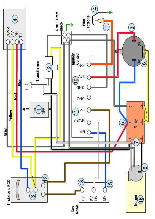
1 The Universal TM gas LowNOx series water heaters contain an electronic spark ignition system. The heater is connected to a 120VAC power source required by the transformer. The transformer steps down the 120VAC to 24- volt AC control voltage. When the heater is turned on (1), a black wire carries power to the 24V step-down transformer and the relay switch. The yellow wire from the transformer (2) carries the 24V from the transformer to the thermostat. In a normal stand-by condition, 24V is passed directly to the damper assembly by the yellow wire and connected to the 24V terminal. This terminal controls the closing of the damper after the thermostat is satisfied. When the thermostat calls for heat (3), contacts close and pass the 24V through the blue wire to the damper assembly TH terminal. A microswitch inside the damper does two things. (4) First, the microswitch breaks contact from the 24V terminal that closes the damper and connects the TH terminal. The TH terminal provides power to the damper motor that drives the damper blade open. The damper blade, being open, will allow combustion gases to escape through the flue ways and vent. Second, when the damper is opened to the correct position, a microswitch passes the 24V control voltage to the Relay switch. (5) The relay switch becomes a critical safety device as well as a power controller. 24V power is passes along the blue wire to the pressure switch to verify the switch is open (6). If this safety is passed, then the relay allows 120V power to pass (7) to the blower motor. The blower motor ramps up and creates a positive pressure for the pressure switch. The pressure switch closes (9) and 24V power is passed to the 24V terminal of the Honeywell control Power is now being supplied to the 24V terminal of the control (10) by the red wire. This is the only wire that feeds power to the control. The control now starts a 90 second try for ignition. It may only take a second or two for the pilot burner to ignite. The control attempts two events simultaneously. The ignition control generates a 10,000 volt spark at the pilot electrode assembly (11) and attempts to light the pilot. You will hear a distinctive clicking or arcing noise. At the same time the control sends 24V from the PV (pilot valve) terminal (11) to the ECO along the brown wire. (12) If the ECO has been tripped due to an overheated tank, the sequence will stop here. The spark ignitor will continue to spark for 90 seconds; then stop. If the ECO is not tripped, 24V is relayed through the ECO to the PV terminal of the gas valve (13) along the brown wire. This activates the first automatic valve and pilot gas is allowed to flow through the pilot supply tube to the pilot burner. The pilot gas is ignited by the sparking pilot electrode and the pilot flame (14) is established. Through a flame recognition of at least one microamp (a very small electrical current produced by the flame), the ignition control ends the spark generation. After the pilot is lit and recognized by the electronic controls, the ignition control energizes the main valve. The ignition control opens the second automatic valve by relaying 24V from the MV (main valve) terminal (15) to the gas control valve along the blue wire. Gas begins to flow to the main burner while the pilot light remains lit. The main burner lights (16) and begins to heat the water in the tank. When the water temperature reaches thermostat setting, the thermostat contacts (3) will open and suspend power to the damper assembly. Several things will happen. First, without 24V relayed by the blue wire, the damper motor closes the damper blade. How does this happen? Remember the microswitch and yellow wire connected to the 24V terminal of the damper? The microswitch reconnects the 24V terminal and relays power to the damper motor to reverse direction and close. Second, without 24V relayed by the red wire, the relay switch and eventually the control will not receive power. The pilot valve and main valve, held open by 24V, are closed. The main burner will shut off and the heater is back into stand-by mode. Page 1
2 Sequence of Operations All voltages are AC and can be measured to ground. Tank is cold and full of water. Heater is wired to a 120 VAC source. Gas supply is connected to heater and valve is set to ON position. (1) 120V is extended from the switch to the 24V step down transformer. 24V is extended from the transformer (2) to the thermostat. (3) Thermostat demands heat. 24V is extended through the blue wire to the damper motor. (4) Damper opens. 24V is extended through the red wire to the relay. (5) (6) At the same time, 24V is passes via the #6 pigtail at the relay from damper to the pressure switch along the blue wire. NOTE: The yellow wire on the pressure switch is a common wire. It does not have any power to ground. Relay circuit performs safety check on pressure switch. Verifies the pressure switch is open thru 24V blue wire and yellow wire. Fill tank Replace fuse or reset breaker at service panel Turn gas valve to ON Turn ON/OFF switch to ON Check for 120V at the transformer Check for 24V at the thermostat Check for 24V at the damper motor Check for 24V at the 24V and 24V GND terminals of the ignition control Check for damper binding or obstruction Verify 24V at red wire on the relay Verify 24V at the blue wire NC terminal of the pressure switch. The yellow spade terminal on the pressure switch is the largest of three terminals. Connects only fit one way. The red and the blue wires spade terminals are the same size and must be positioned on the relay as follows: Blue wire: NC (normally closed) (6) Red wire: NO (normally open) (9) If the blue wire is not connected to the pressure switch, the safety check fails and the blower will not come on. If the pressure switch is damaged and stuck closed, the safety check fails and the blower motor will not come on. Replace switch Check wiring to switch Check gray grounding wire. Replace transformer Replace damper assembly Remove obstruction Page 2
3 (7) If the safety check passes, 24V causes the connection inside the relay to close allowing120v (hot side) to pass to blower. (8) The blower motor creates a positive pressure inside the mixing chamber and causes the pressure switch to close. (9) Closing the pressure switch causes 24V power to move to the control thru the red wire. 24V is extended from the ignition control (10) to the pilot electrode. (11) You should hear it sparking. At the same time, 24V is extended to the ECO. (12) 24V is extended through the ECO to the pilot side PV terminal of the gas valve. (13) (14) Pilot flame ignites and remains lit. Spark generator shuts off. Blower motor should come on. Verify 120V to ground at #3 on relay; then on #1 on relay. Verify positive pressure at 0.2 inches w/c. Check to see if the tube is free & clear. Verify blower motor is operating. Verify 24V at the red wire on the pressure switch or on the 24V terminal of the control. Check to see if the tube is free & clear. Check for 24V at the PV and GND terminal of the ignition Electric spark generator in the ignition produces a continuous 10,000V spark pulse through the orange cable. Visually check pilot electrode assembly for a spark Check ignition cable for continuity Check for 24V at the PV terminal of the gas valve ECO may be tripped due to water too hot Remember - At the same time there is power at the PV terminal of the gas valve, the pilot electrode should be sparking. Check gas control valve. Verify 24V at the PV terminal of the gas valve. Verify minimum gas pressure at the inlet and outlet sides of the gas valve. Check grounding of pilot electrode assembly Check pilot electrode for cracks Check gap of pilot electrode Pilot flame is rectified by the ignition control Check and replace relay. Verify 120V to unit. Replace control Replace pilot electrode cable Cool tank to reset ECO Replace ECO Check gas pressure Check pilot burner for obstructions Replace gas valve Tighten pilot electrode assembly Replace pilot electrode Gap to 1/8 Page 3


4 (15) 24V is extended to the MV terminal of the gas valve. Main burner ignites (16). Water is heated to thermostat setting. Water is hot. Thermostat opens and suspends power to damper motor. Damper closes. Blower motor, main burner, and pilot shut off. Check for 24V at the MV terminal of the ignition control Verify minimum gas pressure at the inlet and outlet sides of the gas valve. Check main burner supply tube and burner tray for obstructions Check for 24V at the MV terminal of the gas valve Verify calibration of thermostat Check thermostat Check damper for obstructions to closing Check for 24V at the 24V and COM terminal of damper motor Heater is in stand-by until the thermostat demands heat Adjust gas pressure Clean or replace Replace gas valve Replace damper assembly Sequence of Operations on Relay Switch: volts from Damper (red wire) applied to Pin #6. Power is forwarded along the blue wire to the NC terminal of the Pressure switch V travels thru the pressure switch to the C terminal of the switch and back to pins #4 and #5 on the relay. 3. The 24V at pin #5 and #2 (ground side) energizes a coil inside the relay. This coil closes switches inside the relay between pins #4 and #6; and between pins #1 and # volts waiting at pin #3 is forwarded thru pin #1 and provides power to the blower motor via the black wire. 5. The blower comes up to speed and pressurizes the plenum box of the burner assembly. This causes the pressure switch to operate and close. 6. The pressure witch closes from terminal C to the NO terminal. At the same time, power is disconnected from the NC terminal V is now routed from the pressure switch to the ignition control via the red wire. Page 4
5 Page 5
f i r e - p a r t s. c o m
 System Overview: The primary components that are included in the SIT Proflame II GTMFS System Gas Valve Integrated Fireplace Control (IFC) SIT Pilot Assembly Transmitter (remote control) (GTMF model) 2
Troubleshooting Electronic Ignition
 Troubleshooting Electronic Ignition Bob Wise CVC Coaching This session is designed to provide a broad approach to troubleshooting electronic ignition systems. Various hearth electronic systems will be
Modulating Furnace Information. Warning on Meter Setting - Read First!
 Modulating Furnace Information Pressure Transducer Pressure DC Volts 0.00" 0.25 0.20" 0.63 0.25" 0.72 0.30" 0.82 0.35" 0.91 0.40" 1.00 0.45" 1.09 0.50" 1.19 0.55" 1.28 0.60" 1.38 0.65" 1.47 0.70" 1.56
E Series CE Approved Intermittent Pilot Ignition Control
 Installation Instructions Issue Date January 11, 2013 E Series CE Approved Intermittent Pilot Ignition Control Application The E Series CE Approved Intermittent Pilot Ignition Control is a safety control
SERVICE MANUAL (INTERNATIONAL)
") SERVICE MANUAL (INTERNATIONAL) IMPINGER CONVEYOR OVENS MODEL 1433-000-E, 1434-000-E, 1456, 1457 WITH PUSH BUTTON CONTROLS Lincoln Foodservice Products, LLC 1111 North Hadley Road Fort Wayne, Indiana 46804
SERVICE MANUAL (INTERNATIONAL) IMPINGER CONVEYOR OVENS MODEL 1433-000-E, 1434-000-E, 1456, 1457 WITH PUSH BUTTON CONTROLS Lincoln Foodservice Products, LLC 1111 North Hadley Road Fort Wayne, Indiana 46804
BLOWER VACUUM SWITCH FAILED OPEN
 F1 F1 AC BLOWER VACUUM SWITCH FAILED CLOSED AC BLOWER VACUUM SWITCH FAILED CLOSED UHS If the blower vacuum switch is closed before blower start-up, the control module will not start the blower. Pre-check
Troubleshooting Manual
 Troubleshooting Manual NOTICE: DO NOT DISCARD THIS MANUAL Models: LEGACY42-IFT PHOENIX42-IFT 1 TABLE OF CONTENTS A. Normal Operation...3 B. Wiring Diagram...4 C. Troubleshooting IntelliFire Touch...5 D.
This Manual is prepared for the use of trained Vulcan Service Technicians and should not be used by those not properly qualified.
 SERVICE MANUAL GRA SERIES GAS FRYERS WITH KLEENSCREEN PLUS FILTRATION SYSTEMS 2GR45AF KLEENSCREEN FRYER BATTERY MODEL ML MODEL ML 1GR45A 136647 3GR85AF 136655 1GR65A 136648 4GR45AF 136656 1GR85A 136649
X4 Installation and Operation Manual - POWER FLAME INCORPORATED
 7.13.2 Set the burner s combustion air inlet damper to the approximate setting as shown in this manual for the desired firing rate. Also, verify that the correct main orifice is installed in the main orifice
PAGE 1. TES Operation & Testing Guidelines: Tes Trouble shooting
 PAGE 1 This document outlines questions to ask and components to check during TES troubleshooting. More detailed troubleshooting procedures are available in the TES Troubleshooting Guide. 1. Flow Light
SERIES VAC Microprocessor Based Direct Spark Ignition Control FEATURES DESCRIPTION APPLICATIONS THE TOTAL SOLUTION FOR GAS IGNITION CONTROL
 SERIES 35-72 120 VAC Microprocessor Based Direct Spark Ignition Control 35.72.03 FEATURES Two Mounting Configurations Open Board With Stand-Off's - saves space and cost Potted - protection for washdown
EC 200 EC 300 GE 360 GE 400 GE 600 L-S BM
 DIESEL SPACE HEATER - SERVICE MANUAL INDEX 1. CONTROLS AND COMPONENTS 2. FLAME CONTROL CYCLES 3. MAINTENANCE SCHEDULE 4. REPAIR PROCEDURES 1. FAN MOTOR ASSEMBLY 2. FUEL FILTER ASSEMBLY 3. FUEL PUMP ASSEMBLY
SYMPTOM POSSIBLE CAUSES CORRECTIVE ACTION
 Troubleshooting SYMPTOM POSSIBLE CAUSES CORRECTIVE ACTION WILL NOT RUN RUNS BUT WON'T SPRAY LOW SPRAY AT NOZZLE UNEVEN SPRAY PATTERN WILL NOT PRODUCE HOT WATER Pump switch in OFF position Place switch
BG1600M Intermittent Pilot Ignition Control
 Installation Instructions Issue Date March, 00 BG600M Intermittent Pilot Ignition Control Application The BG600M Intermittent Pilot Ignition Control is a safety control designed for indirect burner ignition
G600 Series Replacement Intermittent Pilot Ignition Controls
 Installation Instructions G600 Issue Date 0601 G600 Series ment Intermittent Pilot Ignition Controls Installation IMPORTANT: These instructions are intended as a guide for qualified personnel installing
Q35 Series Automatic Vent Damper System
 Installation Sheets Manual 121 Energy Conservation and Miscellaneous Kits Section Q Technical Bulletin Q35 Issue Date 0999 Q35 Series Automatic Vent Damper System Figure 1: Q35 Automatic Vent Damper System
G72x Series Direct Spark Ignition Controls
 Installation Sheets Manual 121 Gas Combustion Combination Controls and Systems Section G Technical Bulletin G72x Issue Date 1299 G72x Series Direct Spark Ignition Controls Figure 1: G72x Direct Spark Ignition
TROUBLESHOOTING. 1. What is the model and serial number? If you don t know, how old is it? Give description.
 TROUBLESHOOTING There is excellent literature on our website: heatec.com. Look under TEC-NOTE. You will find our newest heater manual. This is full of information (complete with great pictures) on our
Reproduction or other use of this Manual, without the express written consent of Vulcan, is prohibited.
 SERVICE MANUAL GAS BRAISING PANS (30 & 40 GALLON) VG30 VG40 ML-126847 ML-126848 VG40 SHOWN - NOTICE - This Manual is prepared for the use of trained Vulcan Service Technicians and should not be used by
Troubleshooting Guide
 Troubleshooting Guide This guide contains information for identifying and correcting issues that may arise. Applicable Models: i200 i200p i250 i250p i200x i201x i250x i251x iq251 iq251d iq751 iq1001 iq1501
Applies to: Models F, B, FE, and BE with spark pilot
 Form CP-F/B-GC (11/17) R8 Obsoletes Form CP-F/B-GC (Version A.2) Gas Conversion Kits and Instructions Applies to: Models F, B, FE, and BE with spark pilot NOTE: Units with standing (match - lit) pilots
G76x Direct Spark Ignition Controls
 Installation Sheets Manual 121 Gas Combustion Combination Controls and Systems Section G Technical Bulletin G76x Issue Date 0400 G76x Direct Spark Ignition Controls Figure 1: G76x Direct Spark Ignition
SAVANNAH EI & DELUXE SYSTEM TROUBLE SHOOTING GUIDE
 SAVANNAH EI & DELUXE SYSTEM TROUBLE SHOOTING GUIDE ***PLEASE MAKE SURE TO LEARN THE REMOTE TO THE SYSTEM (REFER TO PG 6) AND CHECK THE BATTERIES FIRST!!! (American Flame AF-4000 Series) Intermittent Pilot
Start-up Instructions
 RadMax Burners Page 400-S- Start-up Instructions Read complete instructions before proceeding and familiarize yourself with all the system s equipment and components. Verify that all equipment has been
Table of Contents. Parts Overview 1-3. Tools Needed 4. Recommended Service Parts 4. Gas Fire-Up Check List 5. Troubleshooting Flow Chart 6-9
 GreenSmart TM 2 Parts Overview & Troubleshooting 6/13/2014 Table of Contents Section Page Number(s) Parts Overview 1-3 Tools Needed 4 Recommended Service Parts 4 Gas Fire-Up Check List 5 Troubleshooting
American Flame AF-4000 Series Intermittent Pilot Ignition System Trouble Shooting Guide
 American Flame AF-4000 Series Intermittent Pilot Ignition System Trouble Shooting Guide Contents IPI System Overview Pgs. 2-5 Module Audible Alerts Pgs. 6-7 Module Error Codes Pgs. 8-9 Extension Module
36H Gas Control Product Information
 Single Stage 36H Two Stage 36H 36H Gas Control Product Information The 36H combination gas control valve is a versatile multifunction control designed to meet the requirements for use with intermittent
SERVICE MANUAL RRG SERIES HEAVY DUTY GAS GRIDDLE - NOTICE - ML ML ML RRG Shown
 SERVICE MANUAL RRG SERIES HEAVY DUTY GAS GRIDDLE 24RRG 36RRG 48RRG 60RRG ML-135339-00024 ML-135340-00036 ML-135341-00048 ML-135342-00060 24RRG Shown - NOTICE - This Manual is prepared for the use of trained
HVF110, 210, 310, 410HD
 342 N. Co. Rd. 400 East Valparaiso, IN 46383 219-464-8818 Fax 219-462-7985 www.heatwagon.com Installation and Maintenance Manual Please retain this manual for future reference. HVF110, 210, 310, 410HD
INSTALLATION DATA 712 Series Pilot
 INSTALLATION DATA 712 Series Pilot Ignition Systems (FLAME RECTIFICATION) LOCKOUT MODEL 712-005 712-006 712-008 712-009 NON-LOCKOUT MODELS 712-005 712-016 712-017 712-019 712-022 CSA DESIGN CERTIFIED TO
Hayward error codes and troubleshooting
 http://waterheatertimer.org/intermatic-trippers-and-parts.html#pool 50 Hayward error codes and troubleshooting Section V. TROUBLESHOOTING http://www.hayward-pool.com/prd/in-ground-pool-manuals_10201_10551_14502_-1
SERIES VAC Microprocessor Based Direct Spark Ignition Control with Combustion Blower Relay FEATURES DESCRIPTION
 SERIES 35-71 120 VAC Microprocessor Based Direct Spark Ignition Control with Combustion Blower Relay 35.71.02 FEATURES 3 Enclosure Configurations Case and Cover - dust and foreign object protection Open
Replacement Parts List. Armor Condensing Water Heater. AW 151 thru 801. AWII-RP_ _ _Rev V
 Replacement Parts List PARTS & SERVICE DEPARTMENT Nashville, Tennessee 615-889-8900 Fax: 615-882-2918 parts_team@lochinvar.com www.lochinvar.com Armor Condensing Water Heater AW 151 thru 801 41 4 10 38
TROUBLESHOOTING GUIDE FOR HEAT PUMP BOOSTERS MODELS: HPB11, HPB15, & HPB22
 V3 TROUBLESHOOTING GUIDE FOR HEAT PUMP BOOSTERS MODELS: HPB11, HPB15, & HPB22 PREFACE This guide contains instructions for troubleshooting the Steffes Corporation room heating units: Models HPB 11, HPB
PT-M90 Automatic Full-Sequence Modulation Gas Control System
 PT-M90 PT-M90 Automatic Full-Sequence Modulation Gas Control System PT-M90 Module System Illustration Pucada.Tech M901-0316 Gas Valve (PT-V1C-with step motor) A Profile Dimension: Length(84mm) * Width(40mm)
Technical Information and Diagnostic Guide
 Technical Information and Diagnostic Guide This guide will assist you in becoming more familiar with the working components of the NITE System and the proper steps and procedures to completely diagnose
Replacement Parts List. Armor Condensing Water Heater. AW 151 thru 801. AWII-RP_ _ _Rev W
 Replacement Parts List PARTS & SERVICE DEPARTMENT Nashville, Tennessee 877-554-5544 Fax: 615-882-2918 parts_team@lochinvar.com www.lochinvar.com Armor Condensing Water Heater AW 151 thru 801 41 4 10 38
INSTALLATION MANUAL ACL 5500 COMBUSTION SAFETY CONTROLLER
 5500 COMBUSTION SAFETY CONTROL INSTALLATION MANUAL FOR 5500 COMBUSTION SAFETY CONTROLLER WARNING This manual must be read in its entirety before installation of this controller. Installation must be performed
HVF110, 210, 310, 410HD
 342 N. Co. Rd. 400 East Valparaiso, IN 46383 219-464-8818 Fax 219-462-7985 www.heatwagon.com Installation and Maintenance Manual Please retain this manual for future reference. HVF110, 210, 310, 410HD
100% OUTSIDE AIR MAKE-UP UNITS WITH DISCHARGE TEMPERATURE CONTROL & c.pco DIRECT DIGITAL CONTROL MODULE
 100% OUTSIDE AIR MAKE-UP UNITS WITH DISCHARGE TEMPERATURE CONTROL & c.pco DIRECT DIGITAL CONTROL MODULE Start-up must be performed by a trained, experienced service person. The following general start-up
Operating Manual. Safety/Process Flare Pilot
 Operating Manual Safety/Process Flare Pilot Pilot Monitor & Relight Ignition System By Prism Integrated Solutions Inc. For product support please contact us at: Toll Free - 877 264 1050 Fax - 780 582 3922
Process switches and PLC circuits
 Process switches and PLC circuits This worksheet and all related files are licensed under the Creative Commons Attribution License, version 1.0. To view a copy of this license, visit http://creativecommons.org/licenses/by/1.0/,
ELECTRONIC FIREPLACE DAMPER
 ELECTRONIC FIREPLACE DAMPER Model: FSE Low Profile Series The Flue Sentinel Electronic Fireplace Damper is designed to increase the comfort and energy efficiency of residential homes with gas-fired fireplaces.
Solstice and Solstice Supreme High Efficiency Gas Fryers SG/SSH Series Service Manual
 Solstice and Solstice Supreme High Efficiency Gas Fryers SG/SSH Series Service Manual Notice In the event of problems or questions about your order, contact the Pitco Frialator factory at (603) 225-6684.
SERVICE MANUAL. K Series Gas Kettles 2/3 Jacketed Stationary and Tilting - NOTICE - K40GL Shown
 SERVICE MANUAL K Series Gas Kettles 2/3 Jacketed Stationary and Tilting K20GL K40GL K60GL K20GLT K40GLT K60GLT ML-136090 ML-136091 ML-136092 ML-136094 ML-136095 ML-136096 K40GL Shown - NOTICE - This Manual
(For serial numbers before w/ analog control)
") SEQUENCE OF OPERATIONS (For serial numbers before 2038616 w/ analog control) MODEL 1154-000-EA NAT. GAS 230 VAC 50 HZ. 1 PHASE MODEL 1155-000-EA LP GAS 230 VAC 50 HZ. 1 PHASE POWER SUPPLY Electrical power
SEQUENCE OF OPERATIONS (For serial numbers before 2038616 w/ analog control) MODEL 1154-000-EA NAT. GAS 230 VAC 50 HZ. 1 PHASE MODEL 1155-000-EA LP GAS 230 VAC 50 HZ. 1 PHASE POWER SUPPLY Electrical power
AHE S - 12 VDC AHE X - 12 VDC AHE X - 12 VDC
 Shop Manual Model Numbers AHE-100-04S - 12 VDC AHE-120-04X - 12 VDC AHE-130-04X - 12 VDC TABLE OF CONTENTS Section 1 Section 2 Section 3 Section 4 General Heater Information 1.1 Component Overview 1.2
Installation, Operation and Maintenance Manual
 Document 481038 Model PVF(-H) and PVG Indirect Gas-Fired Heat Modules Indirect Gas-Fired Furnaces Installation, Operation and Maintenance Manual Please read and save these instructions for future reference.
G821L/G822L Series Integrated Function Direct Spark Ignition Controls
 Installation Sheets Manual 121 Gas Combustion Combination Controls and Systems Section G Technical Bulletin G821L/G822L Issue Date 1199 G821L/G822L Series Integrated Function Direct Spark Ignition Controls
PROFIRE 1100i IGNITION FLAME SAFETY CONTROLLER
 PROFIRE 1100i IGNITION FLAME SAFETY CONTROLLER Cautions WARNING: EXPLOSION HAZARD- -DO NOT SERVICE UNLESS AREA IS KNOWN TO BE NON- HAZARDOUS -DO NOT OPEN WHEN ENERGIZED EXPLOSION HAZARD- -SUBSTITUTION
36C and 36D Gas Control Product Information
 6C and 6D Gas Control Product Information The 6C and 6D combination gas control valves are compact multifunction controls designed to meet requirements for use with Standing Pilot systems and all types
Replacement Parts List. Armor Condensing Water Heater. AW 150 thru 800
 AW-RP_100160820_2000000353_Rev Replacement Parts List PARTS & SERVICE DEPARTMENT Nashville, Tennessee 6-889-8900 Fax: 6-882-2918 parts_team@lochinvar.com www.lochinvar.com Armor Condensing Water Heater
Heater Troubleshooting Guides
 Heater Troubleshooting Guides Table Of Contents LRZE, 3 LRZM.. 4, 5 LXi.. 6, 7 LITE LD.. 8, 9 LITE LJ.. 10, 11 LITE LG. 1, 13 LX or LT STANDARD BURNERS 14, 15 LX or LT LOW x BURNERS. 16, 17 HiE 18, 19
Installation, Operation and Maintenance Manual
 Document 481038 Model PVF and PVG Indirect Gas-Fired Heat Modules Indirect Gas-Fired Furnaces Installation, Operation and Maintenance Manual Please read and save these instructions for future reference.
Wiring diagrams on page 29 are for reference only. For detailed vehicle wiring refer to Navistar documents.
 1 10/2014 REV 7 !!Attention!! Before performing diagnostics: Wiring diagrams on page 29 are for reference only. For detailed vehicle wiring refer to Navistar documents. Check for Fault Codes using the
G21Q ENGINEERING DATA. Typical Applications. Bulletin # March 1993
 ENGINEERING DATA ENGINEERING DATA MATCHED REMOTE GAS FURNACES SYSTEMS 50hz G21Q PULSE21 SERIES UP-FLO GAS FURNACES 11.4 to 27.8 kw (39 000 to 95 000 Btuh) Output Add-On Cooling 5.3 thru 17.6 kw (1-1/2
RAYPAK ILLUSTRATED PARTS LIST
 RAYPAK ILLUSTRATED PARTS LIST The parts listed are for standard equipment for this model type. Raypak reserves the right to substitute, delete or change any part without notification. The addition of options
Service Bulletin. (This bulletin and all other active bulletins are downloadable from our website at
 Bulletin 00--ABDE Service Bulletin (This bulletin and all other active bulletins are downloadable from our website at www.frymaster.com/parts_service.) Bulletin 00--ABDE Page of + Worksheets Date: 0//00
SECOND GENERATION Use this guide with unit serial number prefix beginning with BWF using Terra Power separator.
 Technical Information and Diagnostic Guide for SECOND GENERATION Use this guide with unit serial number prefix beginning with BWF using Terra Power separator. This guide will assist you in becoming more
SERVICE MANUAL (INTERNATIONAL)
") SERVICE MANUAL (INTERNATIONAL) IMPINGER CONVEYOR OVEN MODEL 1100-000-A SERIES (SN 2038615 & BELOW) SERVICE MANUAL Lincoln Foodservice Products, LLC 1111 North Hadley Road Fort Wayne, Indiana 46804 United
SERVICE MANUAL (INTERNATIONAL) IMPINGER CONVEYOR OVEN MODEL 1100-000-A SERIES (SN 2038615 & BELOW) SERVICE MANUAL Lincoln Foodservice Products, LLC 1111 North Hadley Road Fort Wayne, Indiana 46804 United
Mobile Diesel Heaters GRY-D / GRY-I Service Training Course
 Mobile Diesel Heaters GRY-D / GRY-I Service Training Course 1 Rev. No. 3 January 24, 2011 GRY-I Indirect-fired Diesel Heaters GRY-I 15 WU GRYP 50 AP GRY-I 25 WU GRYP 90 AP GRY-I 40 WU GRYP 135 AP 2 GRY-D
Operation of the FFBH is enabled and disabled by the Automatic Temperature Control Module (ATCM).
.") Page 1 of 8 Published : Apr 22, 2004 Auxiliary Heater COMPONENT LOCATIONS Item Part Number Description 1 - Fuel line connection with fuel tank 2 - Auxiliary fuel pump 3 - Fuel fired booster heater GENERAL
Page 1 of 8 Published : Apr 22, 2004 Auxiliary Heater COMPONENT LOCATIONS Item Part Number Description 1 - Fuel line connection with fuel tank 2 - Auxiliary fuel pump 3 - Fuel fired booster heater GENERAL
Crest Heating Boilers FBN(L)
") Replacement Parts List PARTS & SERVICE DEPARTMENT Nashville, Tennessee 877-554-5544 Fax: 615-882-2918 parts_team@lochinvar.com www.lochinvar.com Crest Heating Boilers FBN(L) 751-2001 59 IMG01113 52 65
Replacement Parts List PARTS & SERVICE DEPARTMENT Nashville, Tennessee 877-554-5544 Fax: 615-882-2918 parts_team@lochinvar.com www.lochinvar.com Crest Heating Boilers FBN(L) 751-2001 59 IMG01113 52 65
Installation, Operation and Maintenance Manual
 Document 458295 Automatic Fire Damper Installation, Operation and Maintenance Manual Please read and save these instructions for future reference. Read carefully before attempting to assemble, install,
NIDAC EMC Communicating Motor
 NIDAC EMC Communicating Motor IFC 12 V Variable Speed Connection Variable Speed Connection 12 V = + 12 Volt DC RX = Motor to Furnace Control Data TX = Furnace to Motor Control Data GND = 12 Volt DC Ground
Field proven low emissions. State-of-the-art low NOx firing - adjustable for application flexibility
 -.9- KINEDIZER LE High capacity low NOx gas burners Field proven low emissions. State-of-the-art low NOx firing - adjustable for application flexibility Lower NOx and less excess air than standard KINEDIZER
Start Up Instructions for the Kiln, Page 1 of 2
 Start Up Instructions for the Kiln, Page 1 of 2 1. Turn the Main Breaker at the right side of the panel on. 2. Press the orange [Control Power On] push button. It will light up when pressed. 3. If the
RESIDENTIAL BOILER 95% HIGH EFFICIENCY COMMERCIAL BOILER 93% HIGH EFFICIENCY
 RESIDENTIAL BOILER 95% HIGH EFFICIENCY WARRANTY: 12 YEARS LIMITED AGAINST LEAKS; PARTS = 1 YEAR STANDARD EQUIPMENT: PLASTIC TEE & COUPLING W/SCREENS, 30 PSI RELIEF VALVE, 0-60 PSI PRESSURE AND TEMPERATURE
RAYPAK ILLUSTRATED PARTS LIST
 COMMERCIAL MODELS: MVB 503A THRU 2003A CATALOG NO. 9300.744 Effective: 12-01-17 Replaces: 03-01-17 RAYPAK ILLUSTRATED PARTS LIST MODEL SIZES: 503A, 753A, 1003A, 1253A, 1503A, 1753A & 2003A MODEL TYPES:
Specifications of STICKTITE and PILOTPAK Nozzles
 Low Temperature urners - STICKTITE and PILOTPK Nozzles 1-1.1-5 Specifications of STICKTITE and PILOTPK Nozzles This graph indicates the relationship between capacity and applied mixture differential pressure
NSGV PT-1000 PORTABLE WELDING STATION I, O & M MANUAL
 APPLICATION OF DUST CONTROL EQUIPMENT: CAUTION - Warning Improper operation of dust control system may contribute to conditions in the work area or facility that could result in severe personal injury
SERVICE MANUAL (DOMESTIC)
") SERVICE MANUAL (DOMESTIC) IMPINGER CONVEYOR OVENS IMPINGER II - ADVANTAGE SERIES Lincoln Foodservice Products, LLC 1111 North Hadley Road Fort Wayne, Indiana 46804 United States of America Phone : (800)
SERVICE MANUAL (DOMESTIC) IMPINGER CONVEYOR OVENS IMPINGER II - ADVANTAGE SERIES Lincoln Foodservice Products, LLC 1111 North Hadley Road Fort Wayne, Indiana 46804 United States of America Phone : (800)
Technical Information and Diagnostic Guide RestStar Use this guide with 5700XE RestStar Unit. Western Star 5700XE.
 Western Star 5700XE RestStar 4 10-2017 1 Technical Information and Diagnostic Guide RestStar Use this guide with 5700XE RestStar Unit 2390 Blackhawk Road P.O. Box 6007 Rockford, IL 61125 nitesystem.com
The Combustex Pilot Pro 800 Pilot Burner Assembly with Ignition & Flame Failure Monitor
 OPERATIONS MANUAL The Combustex Pilot Pro 800 Pilot Burner Assembly with Ignition & Flame Failure Monitor Safe, reliable ignition and flame failure protection combined with a proven, completely self-powered
Primary Controls. Chapter 11. Introduction. Functions of the primary control
 Chapter 11 Introduction The safe, automatic operation of an oilheat system is dependent on the interaction between: The thermostat, which opens and closes a circuit based on temperature changes in the
G23 Bulletin # September 1998 Supersedes June 1995
 ENGINEERING DATA ELITE 80Z UP-FLOW GAS FURNACES *80.0% to 80.8% A.F.U.E. 50,000 to 150,000 Btuh (14.7 to 44.0 kw) Gas Heating Input 1 thru 6 Tons (3.5 thru 21.1 kw) Nominal Add-On Cooling *Isolated Combustion
S8600B,C,H,M; S8610B,C,H,M; S8670D,E,J,K Intermittent Pilot Gas Ignition Control
 S8600B,C,H,M; S8610B,C,H,M; S8670D,E,J,K Intermittent Pilot Gas Ignition Control APPLICATION The 8600 family of ignition controls provide ignition sequence, flame monitoring safety shutoff for intermittent
COMMERCIAL and POOL MODELS: 302C THROUGH 902C
 COMMERCIAL and POOL MODELS: 302C THROUGH 902C CATALOG NO. 9300.753 Effective: 12-01-17 Replaces: 12-01-16 RAYPAK REPLACEMENT PARTS MODEL SIZES: 302C, 402C, 502C, 652C, 752C & 902C MODEL TYPES: HI DELTA
AM SERIES PULSE BOILER TROUBLESHOOTING GUIDE FOR CERTIFIED CONTRACTORS ONLY
 AMP8-1203 AM SERIES PULSE BOILER TROUBLESHOOTING GUIDE FOR CERTIFIED CONTRACTORS ONLY 260 NORTH ELM STREET WESTFIELD, MA 01085 (413) 568-9571 FAX (413) 568-9613 5211 CREEKBANK ROAD MISSISSAUGA, ONTARIO
Up to 96% AFUE, Single Stage, PSC Gas Furnace EASIER TO SELL
 N9MSE Product Specifications Up to 96% AFUE, Single Stage, PSC Gas Furnace EASIER TO SELL Up to 96% AFUE in upflow and horizontal positions, Up to 96% AFUE in downflow positions California NOx approved
Grout Pump Automatic & Manual Troubleshooting Gas Wiring Diagram
 Grout Pump Automatic & Manual Troubleshooting 40-500 Gas Wiring Diagram Turn engine off and relieve hydraulic pressure and grout pressure before troubleshooting. Note: Typically there is a wiring diagram
PARTS LIST FOR SH-100LP, SH-155LP AND SH-375LP
 PARTS LIST FOR SH-100LP, SH-155LP AND SH-375LP Space Heaters This Parts Listing has been compiled for your benefit. You can be assured your space heater was constructed and designed with quality and performance
RAYPAK ILLUSTRATED PARTS LIST
 RAYPAK ILLUSTRATED PARTS LIST The parts listed are for standard equipment for this model type. Raypak reserves the right to substitute, delete or change any part without notification. The addition of options
CX-SERIES ADVANCED BATTERY CHARGER
 CX-SERIES ADVANCED BATTERY CHARGER Table of Content 1. IMPORTANT SAFETY INFORMATION... 2 1-1 General Safety Precautions... 2 1-2 Battery Precautions... 2 2. FEATURES... 3 2-1 Battery Charging Curve...
Cooling Capacity CFM in. w.c. (125 Pa)
") N8MXL Product Specifications 80% ECM Single Stage Heating Furnace EASIER TO SELL 80% AFUE Flame roll out sensors standard Category I venting Blocked vent switch 24 VAC humidifier terminal Electronic air
N8MXL Product Specifications 80% ECM Single Stage Heating Furnace EASIER TO SELL 80% AFUE Flame roll out sensors standard Category I venting Blocked vent switch 24 VAC humidifier terminal Electronic air
Heating and Gas Installations - December 2014
 This is an example of good practice maintenance specifications. It is not exhaustive and should only be used to assist with facilities management or specification of a maintenance contract. Emergency Gas
First Correlating Revision No. 1-NFPA [ Section No ]
![First Correlating Revision No. 1-NFPA [ Section No ]](/thumbs/73/68781388.jpg "First Correlating Revision No. 1-NFPA [ Section No ]") First Correlating Revision No. 1-NFPA 85-2013 [ Section No. 3.3.52.1 ] 3.3.52.1 Booster Fan. A device fan used to assist in the supply of air to, or the removal of flue gas products from, the combustion
First Correlating Revision No. 1-NFPA 85-2013 [ Section No. 3.3.52.1 ] 3.3.52.1 Booster Fan. A device fan used to assist in the supply of air to, or the removal of flue gas products from, the combustion
Cooling Capacity CFM in. w.c. (125 Pa)
") 92.1% AFUE, Single Stage, PSC Gas Furnace EASIER TO SELL 92.1% AFUE, all models all positions, California NOx approved Certified to leak 2% or less of nominal air conditioning CFM delivered when pressurized
92.1% AFUE, Single Stage, PSC Gas Furnace EASIER TO SELL 92.1% AFUE, all models all positions, California NOx approved Certified to leak 2% or less of nominal air conditioning CFM delivered when pressurized
Cooling Capacity CFM in. w.c. (125 Pa)
") 95.5% AFUE, Single Stage, PSC Gas Furnace EASIER TO SELL 95.5% AFUE, all models all positions, California NOx approved Certified to leak 2% or less of nominal air conditioning CFM delivered when pressurized
95.5% AFUE, Single Stage, PSC Gas Furnace EASIER TO SELL 95.5% AFUE, all models all positions, California NOx approved Certified to leak 2% or less of nominal air conditioning CFM delivered when pressurized
RAYPAK ILLUSTRATED PARTS LIST
 COMMERCIAL/POOL MODELS: MVB 504A THRU 2004A CATALOG NO. 9300.745 Effective: 11-01-18 Replaces: 12-01-17 RAYPAK ILLUSTRATED PARTS LIST MODEL SIZES: 504A, 754A, 1104A, 1504A & 2004A MODEL TYPES: MODULATING
SYSTEM CONTROL KIT. Model: CK-41F ITEMS INCLUDED IN KIT:
 SYSTEM CONTROL KIT Model: CK-41F ITEMS INCLUDED IN KIT: 1) Junction box with mounted pressure switch and post purge timer 1) Fan control gas pressure switch 1) 2 ft. length of 1/4 inch aluminum tubing
WAC Air Curtains Technical Guide
 TGWAC-2 WAC Air Curtains Technical Guide FOR WIND STOPPING, INSECT CONTROL, AND ENVIRONMENTAL SEPARATION IN COMMERCIAL AND INDUSTRIAL APPLICATIONS TABLE OF CONTENTS Introduction......................................................................2
Specifications of STICKTITE and PILOTPAK Nozzles
 -.-5 Specifications of STICKTITE and PILOTPK Nozzles This graph indicates the relationship between capacity and applied mixture differential pressure for STICKTITE and PILOTPK nozzles when fed with an
Cooling Capacity CFM in. w.c. (125 Pa)
") 95.5% AFUE, Single Stage, PSC Gas Furnace EASIER TO SELL 95.5% AFUE, all models all positions, California NOx approved Certified to leak 2% or less of nominal air conditioning CFM delivered when pressurized
95.5% AFUE, Single Stage, PSC Gas Furnace EASIER TO SELL 95.5% AFUE, all models all positions, California NOx approved Certified to leak 2% or less of nominal air conditioning CFM delivered when pressurized
Cooling Capacity CFM in. w.c. (125 Pa)
") 92.1% AFUE, Single Stage, PSC Gas Furnace EASIER TO SELL 92.1% AFUE, all models all positions, California NOx approved Certified to leak 2% or less of nominal air conditioning CFM delivered when pressurized
92.1% AFUE, Single Stage, PSC Gas Furnace EASIER TO SELL 92.1% AFUE, all models all positions, California NOx approved Certified to leak 2% or less of nominal air conditioning CFM delivered when pressurized
JBI Docupunch P33 Automatic Punch
 JBI Docupunch P33 Automatic Punch Instruction Manual Provided By http://www.mybinding.com http://www.mybindingblog.com TABLE OF CONTENTS SECTION I: INSTALLATION & TESTING: 1) Uncrating, Inspection & removal
U S A INSTALLATION GUIDE EP400 / E8-B
 U S A INSTALLATION GUIDE EP400 / E8-B www.easycar-.com Before Beginning the Installation 1. Wire Connection Guides Please read this entire installation guide before beginning the installation. The installation
OPERATION MANUAL MODELS TWE-250 TWE-321 TWE-375 TRU WELD EQUIPMENT COMPANY 6400 N. HONEYTOWN ROAD SMITHVILLE, OHIO (330)
") OPERATION MANUAL MODELS TWE-250 TWE-321 TWE-375 TRU WELD EQUIPMENT COMPANY 6400 N. HONEYTOWN ROAD SMITHVILLE, OHIO 44677 (330) 669 2773 CONTENTS Section Description Pages 1 Introduction 3 2 External Features
OPERATION MANUAL MODELS TWE-250 TWE-321 TWE-375 TRU WELD EQUIPMENT COMPANY 6400 N. HONEYTOWN ROAD SMITHVILLE, OHIO 44677 (330) 669 2773 CONTENTS Section Description Pages 1 Introduction 3 2 External Features
Troubleshooting 3Z8 038 Rev B
 Troubleshooting 3Z8 038 Rev B INSTRUCTIONS WARNING INJECTION HAZARD This form is only a quick reference for troubleshooting Graco sprayers. To reduce the risk of serious injury, including fluid injection,
Troubleshooting Guide
 Troubleshooting Guide *For Authorized Gas Technicians Use Only* 1 Table of Contents Introduction 3 Tools and Instruments 4 Intellifire Component Parts 5 Intellifire Basics 7 Problem: The Ignitor makes