JRVCS105 TROUBLESHOOTING GUIDE
|
|
|
- Pierce Long
- 5 years ago
- Views:
Transcription
 and Display Commander (DC), system")

1 JRVCS105 TROUBLESHOOTING GUIDE This guide is made to ease troubleshooting the in-command system. It will cover the wiring code and where those wires are connected to the Body Control Module (BCM) and Display Commander (DC), system functions, and what to look for to discern where a problem could be. Body Control Module (BCM) Display Commander (DC) Table of contents...page 1 Keystone wiring code...page 2 Body Control Module wiring diagram...page 3 BCM Pin Values...Page 4 Device Pairing & Functionality Testing...Page 5-10 Troubleshooting...Page Page 1


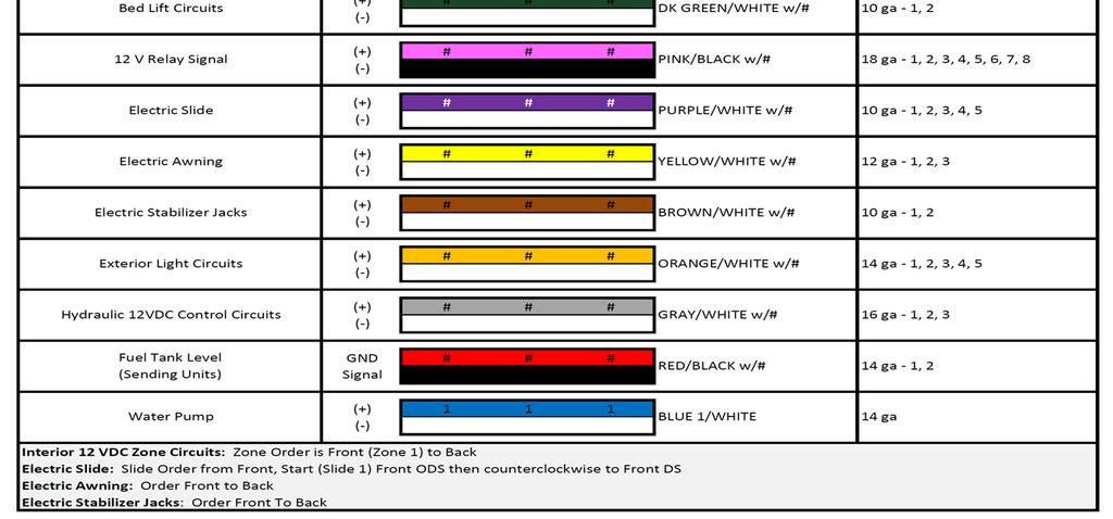
2 Keystone 12 VDC Wire Standard Page 2

3 Electric Wiring Guide for the BCM BCM Pins 1-18 are on the Left side, ascending from Top to Bottom. BCM Pins on the Right side, ascending from Bottom to Top. BCM Pins GND, RX, TX, and +12V DC (DC RX/TX wires) are at the Top Right side. Page 3
4 BCM Pin Values TANK LEVEL Pin NAME BCM FUNCTION NOTE A DMM 1 FRESH 1 TANK IN 0-185KOHM 2 BLACK 1 TANK IN 0-185KOHM 3 BLACK 2 TANK IN 0-185KOHM 4 GREY 1 TANK IN 0-185KOHM 5 GREY 2 TANK IN 0-185KOHM 6 GREY 3 TANK IN 0-185KOHM INPUT FROM SENDING UNIT SINGLE WIRE WORKS ON RESISTANCE INPUT FROM SENDING UNIT SINGLE WIRE WORKS ON RESISTANCE INPUT FROM SENDING UNIT SINGLE WIRE WORKS ON RESISTANCE INPUT FROM SENDING UNIT SINGLE WIRE WORKS ON RESISTANCE INPUT FROM SENDING UNIT SINGLE WIRE WORKS ON RESISTANCE INPUT FROM SENDING UNIT SINGLE WIRE WORKS ON RESISTANCE 0-.74V = EMPTY ( ) V= 1/3 ( ) V = 2/3 ( ) 3.6V = FULL ( ) MEASURE FROM PIN 9 TO EACH INPUT 7 7 VDC COMMON OUTPUT TO TANK SENDING UNITS MEASURE FROM PIN 33 7VDC VDC VDC VDC VDC VDC VDC 8 LIGHT GROUP 12V 15A IN INPUT FROM MAIN BREAKER BOX 12VDC 9 LIGHT GROUP1 GND JUST A TERMINAL NO PCB TRACE NEEDED GND LIGHTING I/O 10 LIGHT GROUP1 12V 15A OUT OUTPUT 12VDC FROM PIN 8 LIGHT IN 12V 12VDC 11 LIGHT GROUP2 GND JUST A TERMINAL NO PCB TRACE NEEDED 15A GND 12 LIGHT GROUP2 12V 15A OUT OUTPUT 12VDC FROM PIN 8 LIGHT IN 12V 12VDC 13 AWNING LIGHT GND GND PASS THROUGH CONNECTION GND 14 AWNING LIGHT 12V 5A OUT POWER FROM 15A INPUT 12VDC V WATER HEATER FAULT IN RECEIVE 12V FAUILT SIGNAL 12VDC Water Heater 16 WATER HEATER GND GND PASS THROUGH CONNECTION GND 17 WATER HEATER GAS +12V 1A OUT OUTPUT 12VDC TO GAS 12VDC 18 WATER HEATER ELECTRIC +12V 1A OUT OUTPUT 12VDC TO ELECTRIC TRAVEL LOCK 19 LOCKOUT SIGNAL IN 12V 12V INPUT FROM TOW VEHICLE BRAKE LOCK OUT SLIDES, JACKS & AWNINGS WHEN PRESENT 12VDC 12VDC Water Pump AWNING Slides Power 20 WATER PUMP +12V OUT 10A Output 12V to WATER PUMP 12VDC 21 WATER PUMP GND JUST A TERMINAL NO PCB TRACE NEEDED GND 22 WATER PUMP +12V IN 10A INPUT FROM MAIN BREAKER BOX 12VDC 23 GND OUT (AWNING#1) OUTPUT 12V POWER & GROUND 24 12V OUT 15 AMP (AWNING#1) OUTPUT 12V GROUND & POWER 25 GND OUT (SLIDE#4) OUTPUT 12V IN POWER & GROUND 26 12V OUT 30 AMP (SLIDE#4) OUTPUT 12V IN GROUND & POWER 27 GND OUT (SLIDE#3) OUTPUT 12V IN POWER & GROUND 28 12V OUT 30 AMP (SLIDE#3) OUTPUT 12V IN GROUND & POWER 29 GND OUT (SLIDE#2) OUTPUT 12V IN POWER & GROUND 30 12V OUT 30 AMP (SLIDE#2) OUTPUT 12V IN GROUND & POWER 31 GND OUT (SLIDE#1) OUTPUT 12V IN POWER & GROUND 32 12V OUT 30 AMP (SLIDE#1) OUTPUT 12V IN POWER & GROUND 33 CHASSIS GROUND GROUND GND 15A 30A VDC IN ELECTRIC FEED FROM BATTERY 30A 12VDC VDC IN BCM POWER FROM CONVERTER 15A 12VDC 36 EMPTY TERMINAL NONE Page 4
.")
 The switch and")
 button for 5 seconds. After a moment, the Passcode Screen will appear. Enter your Passcode.")
5 The BCM should be wired correctly, without loose connections, and +12 VDC connected at pin 35. A RED LED will indicate that the BCM is powered and receiving 12 VDC. The DC is connected to the BCM with 4 wires in the upper right corner of the board: ground, receive, transmit, and 12 VDC power in (Gnd, RX, TX, and +12VDC). The toggle switch on the BCM corresponds to the dial underneath it. (In the event where communication between the DC and BCM is lost or the DC is damaged, this switch will enable "manual" functions of the selected devices) The switch and knob are used for Motors 1-5 (which could include slide outs, and awnings) The DC will be mounted in a "all access" area near the entrance. On the DC, hold down the Power ( ) button for 5 seconds. After a moment, the Passcode Screen will appear. Enter your Passcode. If this is the first time the DC has been powered on, an End User License Agreement (EULA)screen will appear. Upon accepting the EULA, the Enter New Passcode screen will appear. Enter your new passcode twice. Page 5

.")

6 The DC will now bring up the Home Screen. If the Floor Plan has been loaded, all the available water tanks, battery voltage, and 3 "Hotkeys" will appear. The hotkeys will turn on the Water Pump, Water Heater, and Interior lighting groups. The DC has 4 physical buttons underneath the LCD Display. These are (from left to right) the Power, Pages, Home, and Return buttons. To power on or off the DC, hold the Power button down for 5 seconds. Touch the power button, and the DC will activate (if powered on). The Pages button will cycle the pages on the DC; from Home, to the Functions page, to the Menu page. The Return button will take you to the previous page. Press the Pages button and observe the Functions Page. Here all the available functions for the RV will be listed. Cycle each function and ensure it works smoothly and corresponds to the correct device. Ensure all the Home Screen "Hotkeys" actuate/turn on the corresponding devices. Page 6


7 When turning on the Water Pump, open the Kitchen Faucet and listen for the pump to turn on. The Water Pump is pressure controlled and will cycle based on demand. During this time the Water Pump button will stay highlighted. The Interior Lights button will turn on all interior lights and stay highlighted when the lights are on. Selecting the Water Heater button will offer 3 settings: Electric, Propane, or Both. When the desired selection is made, the Water Heater button's label will change to reflect the selection and stay highlighted. Select the Water Heater button again to turn it off. Pressing the "Pages" button a second time will take you to the Menu Page. The Buttons on top of the page represent (from left to right): the Function List Menu, Connected Devices List, Bluetooth Menu, Password Menu, Settings Menu, and Information Page. Time to pair a device. Select the Bluetooth Menu ( ). Page 7

.")

8 The Pairing Screen will appear: On the ios Device, go to Settings and turn on Bluetooth. The ios device will automatically begin broadcasting a signal and it will show up in the Unpaired Devices list. Select the device. On both the ios device and the DC, a Pairing Request screen will appear. Accept the paring request. The DC will now be listed in the ios Device's Bluetooth menu (i.e.: JENSENDC05E1F7). Select the DC on the ios device, it will show "Connected" on the device's Bluetooth list, and the ios device will show up in the DC's Paired Devices list. Now open the in- Command App on the device. It will pair and show the Home screen. ios (Apple) Device Page 8
 will show up in the Android's Unpaired list.")
.")
9 The Android Devices pair a little differently: When the Pairing Screen is open on the DC, ensure that Bluetooth is functioning on the Android device, and open the in-command App. Select the Menu button in the Android App and then the Bluetooth button. On the DC press Discover and on the Android device press Scan. The BCM (i.e.: JENSENDC05E1F7) will show up in the Android's Unpaired list. Select the DC. A Pairing Request will show up on the DC and the Android device, accept both. The DC will now appear in the Android's Paired List with yellow font (indicating that it is Actively paired with the DC. There can be more than 1 DC paired to a Android OR ios device). Select the Home button, the DC Pairing screen will appear, then the App will show the Home screen. Android Device The ios and Android device Apps need to have the correct floorplan downloaded from the DC to display the Trailer's functions. On either device (ios or Android) go to the Settings screen and select the Reset button. The Reset Menu will appear. Select Floorplan. The functions will populate on the App's Menu screen. Press the Home button. Tank levels and Battery charge will be listed. Press the Function List button. The Functions will be listed with an activation button next to them. The ios or Android Device is now ready for use. The in-command system can only be paired to 7 devices 4 Android and 3 ios)and only 4 of them can be active (3 Androids and 1 ios). "Active" meaning they can activate functions and receive data. Apple programming dictates that only 1 ios device can be actively paired. To use another ios device that is paired to the in-command system, simply push the ios App's Power button and shut the App down. This will disconnect the device from the BCM without having to go to the ios device's Bluetooth list and disconnecting it. The new ios device will need to have the DC selected in it's Bluetooth settings before opening the App. 3 Android devices are able to be actively paired at one time. If a user wishes to use the 4th paired Android device, simply use the Power button on the device's App that the 4th device will be replacing. The Android device will disconnect to allow the other device to be active. Page 9

10 To verify that the Handheld device is connected to the DC, select the Interior Lights button. All the Interior Lights should cycle with each button press and the corresponding buttons on the DC, and other devices, should cycle from OFF to ON and vice versa. Using the handheld device, cycle through all the functions previously tested on the DC. Ensure the DC display correlates with the handheld device's. While testing the handheld device, push buttons on the DC. Lights should function while using a Motor Function (slide, awning, etc.). Other Motor Functions should NOT be able to actuate while a Motor Function is in use. A "System Busy "message should appear. When connecting multiple handheld devices, connection should be smooth, no other devices should be kicked off, actuation of systems on one device should correspond to the buttons on other devices, and only the non-motorized functions should be able to be actuated by any device while motorized functions are being actuated on another. Next, go to the Connected Devices List ( ). The list should contain all Actively Paired devices with the option to "disconnect" them. Ensure the devices can be disconnected. Last, let's test the Lock Out feature. Apply +12 VDC to the Lock Out circuit by using a wire with clips. Attach one end to Pin 35 and the other to Pin 19. This represents the driver of the tow vehicle stepping on the brake. On the Home page, a Red button will appear with "Travel Lock " on it. All motorized functions are now disabled, but the Hotkeys and lights will still work. Carefully remove the wire attached to Pin 35 and Pin 19. The Red button on the DC's Home page will turn light blue with "Unlock" written on it. To unlock the Travel Lock, this button on the DC must be selected. the Travel Lock cannot be removed with a handheld device for safety reasons. Page 10
11 Troubleshooting Symptom Solution Try cycling the DC with the Power button. Check main fuse in Distribution Panel. Display Commander (DC) will not Press Reset button on BCM. turn ON or no front panel operation Check for 12V+ on +12VDC wire to DC using a Digital Multi-meter. Check ground wire connection to DC. Try cycling power using the RV main breaker. Check if the Red power LED is off, No power to the Body Control Module (BCM), The Red Light is off Check the fuse in the Distribution Panel. Check 12V+ on wire at pin 35. Disconnect wire from pin 7, if BCM powers up, there is a short on the wire. Correct wiring. DC screen flashing on and off after installation Check Ground wire at pin 33. Disconnect and reconnect 12V+ and Ground wires from the back of DC. Cycle power to the BCM and DC. Check wire connections to DC. DC not controlling light or motor functions, and DC is showing 0VDC Electric motors do not move Travel Lock is on *Relay not activating Ensure Battery is charged. Plug in shore power. Swap the TX and RX wires either at the BCM or back of the DC. Check for 12V+ at Pin 34. Ensure the relay activates*. Ensure 12V+ is removed from pin 19. Press Reset button Replace the relay with one from an unused circuit by gently pulling it off the board. Relay is an automotive standard at 12VDC coil, 40/30Amp 14VDC contact Troubleshooting The in-command system is pretty painless. The BCM and DC simulate all the lights, gauges, and switches on the old control panels. The BCM Pin Vales portion of this guide will clear most issues. Basically, if the BCM does not have the desired voltage, or signal input, it will not be able to function or read tanks correctly. Also, if the BCM has the correct output voltage or signal, but nothing is functioning, the problem lies in the wiring leading to the malfunctioning component or the component itself. Any issues that are related to in-command that cannot be cleared using the above list will be tied to the BCM and DC hardware and software. Careful inspection of the BCM will need to be done (possibly blowing the BCM board with air to remove any dust,debris,or conductive material). If the BCM looks clean and undamaged (without burnt or cracked components) with all the wires secure and not touching each other, troubleshooting the program is needed. Contact an ASA representative for questions regarding in-command software or hardware Page 11

12 Above is the Water tank sending unit. The sending unit runs on 7 VDC supplied by the BCM. The 7 VDC signal runs to a sensor embedded into the side of the water tank. The 1/3, 2/3, and Full sensors are then aligned in an ascending diagonal line from the 7 VDC sensor. The "To Tank Input" line runs to the BCM and terminates at Pin s 1-7 depending on the tank. When water or waste starts to fill the tank, it contacts the 7 VDC sensor and the 1/3, 2/3, and Full sensors. The Voltage travels through the 1/3, 2/3, and Full sensor leads to a resistor bank, then out the red wire to the BCM. If the BCM is not receiving the correct voltage (seen on Page 4 BCM Pin Values/Tank Levels in the Notes section) on Pins 1-7, it will not reflect the correct tank level. Should the incorrect voltage be coming from the tank, there could be debris on the sensor (for the Gray and Black tanks), the line to the 1/3, 2/3, or Full sensors are not terminated correctly, the sensors are not installed at the desired angle, or the sensor is bad. Page 12
JRVCS2 TROUBLESHOOTING
 JRVCS2 TROUBLESHOOTING This guide is made to ease troubleshooting the in-command system. It will cover the wiring code and where those wires are connected to the Body Control Module (BCM) and Display Commander
Troubleshooting Guide
 Troubleshooting Guide BCM Pin Values Tanks Lighting I/O s Travel Lockout Water Heater Water Pump Pin Name BCM Function Note A DMM 1 Fresh 1Tank In Input from Sending Unit 2 Fresh 2 Tank In Input from
Troubleshooting Guide
 Troubleshooting Guide RV-C System Layout BCM Pin Values Tanks Interior Lighting I/O Exterior Lighting I/O Pin Name BCM Function Note A DMM 1 Fresh 1 Tank In Input from Sending Unit 2 Fresh 2 Tank In Input
SlimRack Bed Lift System OEM INSTALLATION MANUAL
 SlimRack Bed Lift System OEM INSTALLATION MANUAL Rev: 07.11.2018 TABLE OF CONTENTS System Information 2 Safety Information 3 Resources Required 3 General Requirements 3 Installation 4 SlimRack Bed Lift
OnCommand Troubleshooting Guide Hayward Industries
 OnCommand Troubleshooting Guide 2010 Hayward Industries Table of Contents Safety Precautions Page 1 Overview Pages 2-5 Software Troubleshooting Page 6 Local Display Pages 7-8 Relays Pages 9-10 Heaters
BIM-17-2 Bus Interface Module for compass and outside temperature
 BIM-17-2 Bus Interface Module for compass and outside temperature Mount the temperature sensor in the front grill area or another location that can get good air flow while the vehicle is being driven.
MINOTOUR SERVICE MANUAL
 MINOTOUR SERVICE MANUAL The following areas are covered in this manual: Interlock Feature Vandalock Feature AC System Heaters Passenger Advisory System MINOTOUR SERVICE MANUAL ELECTRICAL TROUBLESHOOTING
e-ask electronic Access Security Keyless-entry
 e-ask electronic Access Security Keyless-entry Multiplex System Multiplex System Installation & Instructions (UM15 ~ 22272-03) Table of Contents Introduction... 1 Standard e-fob Operation and Features...
BIGLA30-T/BIELA14-T Event Codes Quick Reference EXPLANATION CORRECTIVE ACTION PARTS TO CARRY ON SERVICE CALL
 E13 TEMPERATURE PROBE FAILURE E16 HIGH LIMIT 1 EXCEEDED A. TEMP Probe reading out of range. B. Bad Connection. C. Problem with the temperatur e measuring circuitry including the probe. High limit temperature
Installation Guide. Immediate support available at or contact us at
 Installation Guide Professional installation is recommended. ALL HID KITS ARE INSTALLED AT YOUR OWN RISK! OPT7 and its affiliates will not be held liable for any damage or cost associated with installation
Auto-Level Troubleshooting (Old Platform) Electronic Control- Prior to 2009, Pressure Switch Control panel #s 2057, 2058, 2795, 2795B
 Electronic Control- Prior to 2009, Pressure Switch Control panel #s 2057, 2058, 2795, 2795B") Auto-Level Troubleshooting (Old Platform) Electronic Control- Prior to 2009, Pressure Switch Control panel #s 2057, 2058, 2795, 2795B This guide addresses the troubleshooting of electronic controls used
Auto-Level Troubleshooting (Old Platform) Electronic Control- Prior to 2009, Pressure Switch Control panel #s 2057, 2058, 2795, 2795B This guide addresses the troubleshooting of electronic controls used
SUN ELECTRONIC SYSTEMS EC1X HEAT/COOL TROUBLESHOOTING GUIDE
 SUN ELECTRONIC SYSTEMS EC1X HEAT/COOL TROUBLESHOOTING GUIDE 062013 COVERS MODELS EC1x SUN ELECTRONIC SYSTEMS, INC. Tel: 321-383-9400 1845 Shepard Drive Fax: 321-383-9412 Titusville Florida Email:info@sunelectronics.com
11712 Jefferson Ave, Suite C-#446 Newport News, VA Website: Office (757)
") 11712 Jefferson Ave, Suite C-#446 Newport News, VA 23606 E-mail: mpusupport@allteksystems.com Website: www.allteksystems.com Office (757) 546-0742 Manual and Users Guide Version B.4 2 Thank you for purchasing
11712 Jefferson Ave, Suite C-#446 Newport News, VA 23606 E-mail: mpusupport@allteksystems.com Website: www.allteksystems.com Office (757) 546-0742 Manual and Users Guide Version B.4 2 Thank you for purchasing
Installation and User Manual. with RAIN SENSOR.
 with RAIN SENSOR www.solarsmartopener.com Revision..0 TABLE OF CONTENTS Features In The Box Further Items Required Basic Operation Solar Panel and Operator Installation Operator Installation Solar Panel
PF3100 TROUBLESHOOTING SOLUTIONS TO COMMON PROBLEMS. v1.1 Revised Nov 29, 2016
 PF3100 TROUBLESHOOTING SOLUTIONS TO COMMON PROBLEMS v1.1 Revised Table of Contents 1 Common Alarms and Warnings... 1 2 Common Issues... 6 2.1 Communication problems... 6 2.1.1 Controller communication
Model H30 Operation Manual
 Model H30 Operation Manual Model H30 Version 1.0 August 1, 2007 2 135 West Davenport Street Rhinelander WI 54501 Phone: 866.441.7997 Fax: 866.278.0036 info@houstonst.com www.houstonst.com 3 Table of Contents
Read Chapter 8 Servicing Machine in the Manual for general guidelines
 Page 1 of 6 Read Chapter 8 Servicing Machine in the Manual for general guidelines The PlasmaCAM will not work on a GFI circuit. Earth ground the grates of the PlasmaCAM. Computer Configuration A. PlasmaCAM
# Traction Control Window Switch
 1 INSTRUCTIONS # 82085 Traction Control Window Switch Thank you for choosing products; we are proud to be your manufacturer of choice. Please read this instruction sheet carefully before beginning installation,
TABLE OF CONTENTS General information... 4 Benefits of the system... 4 OPERATION CONCEPT... 5 Algorithm of deactivation... 5 Authorization with the
 OPERATING MANUAL Dear car owner! Please note that the AUTHOR Alarm s anti-theft devices are not intended for self-installation. We strongly recommend to install and configure the purchased equipment only
SlimRack Bed Lift System OWNER'S MANUAL
 SlimRack Bed Lift System OWNER'S MANUAL TABLE OF CONTENTS System Information 2 Features 2 Operation 3 Prior to Operating the SlimRack Bed Lift System 3 Raising the Bed 3 Lowering the Bed 3 Troubleshooting
Installation and Operation Manual
 Wireless Technology Enabled Exterior Digital Load Scale 201-EBT-02(B) Installation and Operation Manual Please read carefully before installation The Bluetooth word mark and logos are registered trademarks
SERIES 700/700E FACTORY KEYLESS UPGRADE INSTALLATION MANUAL
 SERIES 700/700E FACTORY KEYLESS UPGRADE INSTALLATION MANUAL Items Supplied with the System: Installation Instructions: Main unit 1. Mounting the module: Plug In LED Mount the module in a suitable location
Eminox Electronic Service Indicator
 ESI Installation and Instruction Manual Eminox Electronic Service Indicator I n s t a l l a t i o n a n d I n s t r u c t i o n M a n u a l LITM004 ESI Installation and Instruction Manual Section Title
SST-3 Start-Stop-Throttle
 SST-3 Start-Stop-Throttle Installation & Operation Guide Revision 1.1 Internet: www.wiredrite.com E-mail: info@wiredrite.com Page 1 CONTENTS Introduction 2 Hardware Mounting 2 Connections 2 Operation &
42 Series Step. Owner's Manual #842A. Equipped with a Permanent Magnet Motor. Table of Contents
 Owner's Manual #842A 10/05 Kwikee #1422258, Rev. 0A ED 42 Series Step Equipped with a Permanent Magnet Motor D IS C O N TI N U For steps with Control Unit 909510000 and steps without Control Units Table
AUTOMATIC CONTROL ROLLING DOOR OPENER
 AUTOMATIC CONTROL ROLLING DOOR OPENER INSTALLATION INSTRUCTION AUTOMATIC OBSTRUCT PHOTOELECTRIC BEAM ROLLING CODE SYSTEM AUTO CLOSE DOOR ANTI-THEFT SYSTEM INSTALLATION INSTRUCTION AND RDO OWNERS MANUAL
Continuing Education Course #206 Introduction to Designing Machine Control Systems Part 2
 1 of 5 Continuing Education Course #206 Introduction to Designing Machine Control Systems Part 2 1. Continuing to answer the following questions indicates that you understands that the presented material
Ground Control TT Leveling System OWNER'S MANUAL
 Ground Control TT Leveling System OWNER'S MNUL TBLE OF CONTENTS System Information 2 Features 2 Safety Information 2 Touch Pad Diagram 3 Operation 4 Basic Jack Operation 4 Unhitching From Tow Vehicle 4
DESCRIPTION & OPERATION
 DESCRIPTION & OPERATION 1998-99 SUSPENSION Electronic - Real Time Damping - Corvette The Real Time Damping (RTD) system automatically controls vehicle ride by independently controlling a damper solenoid
TRITON ERROR CODES ERROR CODE MODEL SERIES DESCRIPTION RESOLUTION
 0 8100, 9100, 9600, 9610, 9615, 9640, No errors 9650, 9700, 9710, 9705, 9750, RL5000 (SDD),RL5000 (TDM), RT2000, 9800, MAKO, SuperScrip 1 9615 Unsolicited note channel 1 2 9615 Unsolicited note channel
Wiring Main Power connector constant 12V power
 DHC-2000 Digital Height Control System Introduction This control system can be connected to a display module and height sensors or pressure senders to allow monitoring and control of all four corners and
LC I LIPPERT COMPONENTS HYDRAULIC FULL WALL SLIDEOUT SYSTEM OPERATION AND SERVICE MANUAL
 LC I LIPPERT COMPONENTS HYDRAULIC FULL WALL SLIDEOUT SYSTEM OPERATION AND SERVICE MANUAL TABLE OF CONTENTS SYSTEM...... 3 Warning...... 3 Description..... 3 Prior to Operation... 4 4 OPERATION... Main
ITCEMS950 Idle Timer Controller - Engine Monitor Shutdown Isuzu NPR 6.0L Gasoline Engine
 Introduction An ISO 9001:2008 Registered Company ITCEMS950 Idle Timer Controller - Engine Monitor Shutdown 2014-2016 Isuzu NPR 6.0L Gasoline Engine Contact InterMotive for additional vehicle applications
Door Lock System Controls
 2017 Chevy Truck Suburban HD 4WD V8-6.0L Vehicle > Body and Frame > Locks > Description and Operation > Components POWER DOOR LOCKS Door Lock System Components The power door lock system consists of the
ADVANCED PID TROUBLESHOOTING
 ADVANCED PID TROUBLESHOOTING August 29, 2016 A KEY POINT If the drive is telling you something via a Fault, then the problem is probably not the drive. The drive is recognizing a fault and telling you
Auger System - Troubleshooting Guide
 Haas Technical Documentation Auger System - Troubleshooting Guide Scan code to get the latest version of this document Translation Available 1. Multi Auger 2. Single Auger Electrical Diagram Copyright
Main 20 A fuse has blown (2) Connector has come off PCB
 Connector has come off PCB") ELECTRICAL FAULT FINDING OMS TRACTORS C & A from September 00 D&K series from April 00 JCB from Jan 00 Note: This Bulletin must be used in conjunction with the correct wiring diagram for the Tractor being
ELECTRICAL FAULT FINDING OMS TRACTORS C & A from September 00 D&K series from April 00 JCB from Jan 00 Note: This Bulletin must be used in conjunction with the correct wiring diagram for the Tractor being
INSTALLATION INSTRUCTIONS
 1551 S. Vineyard Avenue Ontario, CA 91761 (909) 923-1973 INSTALLATION INSTRUCTIONS E-Z-GO Installation Notes CURTIS 1234, 1236 OR 1238 AC INDUCTION MOTOR/ CONTROLLER EZ-GO Curtis Controller Installation
Table Of Contents. Motor Selection Guide Installation Instructions Operators 20-32
 Table Of Contents Motor Selection Guide 2-12 - Shades, Shutters and Doors - Retractable Awnings Installation Instructions 13-1 - Operator Adaptors - Operator Limit Adjustment - Wiring Considerations -
Kwikee IMGL Step Control Testing Procedure #82-ST0500
 Kwikee IMGL Step Control Testing Procedure #82-ST0500 TABLE OF CONTENTS Introduction 2 Resources Required 2 General Service Notes 3 Preparation 5 Troubleshooting and Test Procedures 5 Testing the Step
Unit 5 Troubleshooting
 Unit 5 Troubleshooting Unit Objectives Given a realistic scenario depicting a broken machine, the learner will be able to effectively troubleshoot, diagnosis, and repair the problem returning the machine
User Manual. BMS123 Smart
 User Manual BMS123 Smart Introduction After the introduction of affordable LiFePO4 batteries, off-grid solutions became available for wide public. It is vital that such batteries are charged very carefully.
Complete Home Water Protection
 Valve Complete Home Water Protection leaksmart is an innovative, wireless system that eliminates the threat of water damage by keeping you in constant control of your home s water supply. It not only detects
DTC P0A04 - Open Wiring Fault
 DTC P0A04 - Open Wiring Fault Orion Product Orion BMS [Original] (24-180 Cell) Orion BMS 2 (24-180 Cell) Orion JR (16 Cell) Fault Supported YES YES YES FAULT DESCRIPTION This fault is a serious code that
CLOUDBOX Quick Start Guide
 CLOUDBOX Quick Start Guide Welcome to FuelCloud! This quick start guide will help you get your FuelCloud system installed. Important: Online setup must be complete in order to finish installation and test
System III Wiring Information 54-12
 System III Wiring Information 54-12 System Operation General Information Initial Power On Description of Revisions: This service bulletin is updated and replaces the version dated September 2002. This
DESCRIPTION & OPERATION
 ANTI-THEFT SYSTEM 1998 ACCESSORIES & EQUIPMENT General Motors Corp. - Anti-Theft System DESCRIPTION & OPERATION WARNING: Deactivate air bag system before performing any service operation. See AIR BAG RESTRAINT
TIME REQUIREMENT GUIDE (TRG)
") CAT SWITCHGEAR TIME REQUIREMENT GUIDE (TRG) This warranty repair time requirement guide is designed to: Provide detailed guidance on troubleshooting Determine possible solutions Guide the technician to
CAT SWITCHGEAR TIME REQUIREMENT GUIDE (TRG) This warranty repair time requirement guide is designed to: Provide detailed guidance on troubleshooting Determine possible solutions Guide the technician to
Automotive Diagnostics Using The Controller Area Network (CAN) Denise R. James
 Denise R. James") Automotive Diagnostics Using The Controller Area Network (CAN) Denise R. James Topics Covered Overview of CAN Layout in Vehicle OBD II Little Known Car Bonuses Android App Obtaining OBD II Codes Overview
Automotive Diagnostics Using The Controller Area Network (CAN) Denise R. James Topics Covered Overview of CAN Layout in Vehicle OBD II Little Known Car Bonuses Android App Obtaining OBD II Codes Overview
INSTALLATION MANUAL SPECTRUM BRAKE CONTROL
 INSTALLATION MANUAL 51170 SPECTRUM BRAKE CONTROL TABLE OF CONTENTS Controls & Components Tools List Before You Begin Wiring Wiring Diagram Mounting the LED Display Rotary Knob Wiring the Plug Connector
Spray Height Controller
 Spray Height Controller UC5 SERVICE MANUAL 2012 Printed in Canada Copyright 2012 by NORAC Systems International Inc. Reorder P/N: UC5 SERVICE MANUAL 2012 Rev B NOTICE: NORAC Systems International Inc.
Kelly HSR Series Motor Controller with Regen User s Manual V 3.3. Kelly HSR Opto-Isolated Series Motor Controller with Regen.
 Kelly HSR Opto-Isolated Series Motor Controller with Regen User s Manual HSR72601 HSR72801 HSR12401 HSR12601 HSR12901 HSR14301 HSR14501 HSR14701 Rev.3.3 Dec. 2011 Contents Chapter 1 Introduction... 2 1.1
Power Distribution System User s Manual. Model: PDS-100
 Power Distribution System User s Manual Model: PDS-0 Section Page Product Overview... 1 I) General Information... 2 II) Important Safety Information... 2 III) Installation... 3 A) Materials Provided...
Installation, Operation and Maintenance Manual
 Document 473681 Vari-Green Motor and Controls Installation, Operation and Maintenance Manual Please read and save these instructions for future reference. Read carefully before attempting to assemble,
EPC DC MOTOR SPEED CONTROL
 EPC DC MOTOR SPEED CONTROL OPERATION AND INSTRUCTION MANUAL THIS MANUAL IS PUBLISHED BY EPC CORPORATION AND IS TO BE DISTRIBUTED ONLY WITH NEW EPC CONTROLS AND EQUIPMENT NO OTHER DISTRIBUTION IS PERMITED
Idle Free Systems, Inc. Reference Guide System Component Information
 Idle Free Systems, Inc. Reference Guide System Component Information #68004 REV 3 #68004 REV 3 Idle Free Reference Sheets System Components & Trouble shooting Table of Contents RF # 101.0 102.0 103.0 104.0
Wallbox Commander. User Guide WBCM-UG-002-EN 1/11
 Wallbox Commander User Guide 1/11 Welcome to Wallbox Congratulations on your purchase of the revolutionary electric vehicle charging system designed with cuttingedge technology to satisfy your daily needs.
Sentinel Drive Quick Start Guide for Installers For Inspection Plus and HOS Portable Solutions
 Sentinel Drive Quick Start Guide for Installers For Inspection Plus and HOS Portable Solutions February 2017 Contents About this Document... 3 Setup... 3 Prerequisites... 4 Connecting to Wi-Fi (HOS Portable
EQUALIZER SYSTEMS County Road 3 Elkhart, IN Fax
 EQUALIZER SYSTEMS 55169 County Road 3 Elkhart, IN 46515 800-846-9659 574-264-3437 Fax 574-266-6083 SERVICE INFORMATION FOR GULF STREAM COACH Many of the perceived problems with leveling and slide systems
Table of Contents. Product Registration 18 FAQ 19 Troubleshooting 20 Customer Support / Warranty 21
 Table of Contents Product Overview 01 / 02 Introduction / Warnings 03 / 04 Battery Operation / Battery Maintenance 05 / 07 Battery Installation 05 Charging the Battery 06 Master Code Programming 08 Remote
Installing a Programmed Fronius SCERT in a Managed AC Coupled system
 Installing a Programmed Fronius SCERT in INTRODUCTION This document is included with Fronius SCERT PV Inverters that have been programmed. It applies only to units that have been programmed and are ready
Kwikee Platinum Series OWNER'S MANUAL
 Kwikee Platinum Series OWNER'S MANUAL TABLE OF CONTENTS Safety Information 2 Product Information 2 General Service Notes 3 Prior To Operation 3 Operation 4 Step with Control Unit 4 Troubleshooting 5 Step
3 in 1 TRAIL CHARGER with LOCKOUT
 Owner s Manual P/N: 283821 500 3 in 1 TRAIL CHARGER with LOCKOUT 283821 01 Version 2.04 07/05/2011 Owners Manual Operation Installation Wiring Diagram Troubleshooting Parts Breakdown 1 GENERAL OPERATION
Stay-IN-Play with Panic Stop Braking
 INSTALLATION INSTRUCTIONS TOWED VEHICLE BRAKING SYSTEM Stay-IN-Play with Panic Stop Braking SMI Manufacturing, Inc. P.O. Box 14040 Evansville, IN 47728 1-800-893-3763 www.smibrake.com SIP0906 Model SIP0603
Kwikee Revolution Step Series
 Kwikee Revolution Step Series OWNER'S MANUAL (3010002262) Rev: 07.26.2018 Kwikee Revolution Step Series Owner's Manual 3010002262 TABLE OF CONTENTS Safety Information 2 Product Information 2 General Service
Installation Instructions
 patent pending Portable Proportional Braking System Installation Instructions Part number 9400 Towing and Suspension Solutions ROADMASTER, Inc. 6110 NE 127th Ave. Vancouver, WA 98682 800-669-9690 Fax 360-735-9300
IMPORTANT! Remote Control Instructions
 Remote Control Instructions FOR New Tarp Remote Control Installation Use these in place of the rocker switch and solenoid section of instructions in your roll tarp owner s manual. FOR Existing Electric
Battery Control Center - Diesel
 Service Manual CAUTION: All servicing of the Battery Control Center should be done only by a qualified Service Technician. Inadvertent shorts inside the Battery Control Center could result in severe damage
SERVICE MANUAL. Kysor Instrumentation Troubleshooting Guide
 Kysor Instrumentation Troubleshooting Guide Troubleshooting Emergency One Commercial System The Medallion II instrumentation system is a Microprocessor based system utilizing both Sensor and Data bus information
BASIC TROUBLE SHOOTING (PERFECTPASS FOR MECHANICAL ENGINES) How PerfectPass Works
 How PerfectPass Works") BASIC TROUBLE SHOOTING (PERFECTPASS FOR MECHANICAL ENGINES) How PerfectPass Works Through the in-dash display the driver sets the desired boat speed or engine RPM depending upon which mode of operation
BASIC TROUBLE SHOOTING (PERFECTPASS FOR MECHANICAL ENGINES) How PerfectPass Works Through the in-dash display the driver sets the desired boat speed or engine RPM depending upon which mode of operation
Coleman Air Diversion Controller Model C40
 Coleman Air Diversion Controller Model C40 Designed for 12 volt battery based systems. The Coleman Air model C40 charge controller is a compact, simple to use controller specifically designed for use with
Installation, Operation and Maintenance Manual
 Document 47681 Vari-Green Motor and Controls Installation, Operation and Maintenance Manual Please read and save these instructions for future reference. Read carefully before attempting to assemble, install,
INOVA HIGHTECH Ltd. MEP 002/003 Auto Starter Manual
 INOVA HIGHTECH Ltd. MEP 002/003 Auto Starter Manual Complete Installation and Operating Manual for the MEP 002/003 Auto / Remote Starter for the following MEP Power Generators: MEP 002A/003A/011A/802A/803A/811A
Troubleshooting: Door Jamming and Door Handing 6. Troubleshooting: Keypad 11. Troubleshooting: Smart Home Systems 12. Troubleshooting: Battery 14
 Programming and Troubleshooting Guide 1 2 3 4 5 6 Mastercode 2 Troubleshooting: Door Jamming and Door Handing 6 Troubleshooting: Keypad 11 Troubleshooting: Smart Home Systems 12 Troubleshooting: Battery
FOR New Electric Kit and Remote Control Installation
 Installation Manual COMMAND-10 REMOTE AND COMMAND STATION FOR New Electric Kit and Remote Control Installation Use these in place of the rocker switch and solenoid section of instructions in your roll
LIPPERTCOMPONENTS, INC. HYDRAULIC SLIDEOUT AND HYDRAULIC LANDING GEAR (HLG) SYSTEM OPERATION AND SERVICE MANUAL
 SYSTEM OPERATION AND SERVICE MANUAL") LIPPERTCOMPONENTS, INC. HYDRAULIC SLIDEOUT AND HYDRAULIC LANDING GEAR (HLG) SYSTEM OPERATION AND SERVICE MANUAL TABLE OF CONTENTS SYSTEM...... Warning...... Prior to Operation... Description..... Preventative
LIPPERTCOMPONENTS, INC. HYDRAULIC SLIDEOUT AND HYDRAULIC LANDING GEAR (HLG) SYSTEM OPERATION AND SERVICE MANUAL TABLE OF CONTENTS SYSTEM...... Warning...... Prior to Operation... Description..... Preventative
INSTALLER MANUAL USER MANUAL. Contents
 Installation & user manual two way Contents INSTALLER MANUAL Important information General 1. Technical data 2. Description Installation: 1. Positioning the unit 2. Connection. 3. Parts description. 4.
2015 EDITION SUBMERSIBLE MOTORS AIM MANUAL. APPLICATION INSTALLATION MAINTENANCE 60 Hz, Single-Phase and Three-Phase Motors. franklinwater.
 0 EDITION AIM MANUAL SUBMERSIBLE MORS APPLICATION INSTALLATION 60 Hz, Single-Phase and Three-Phase Motors franklinwater.com All Motors System Troubleshooting Motor Does Not Start A. No power or incorrect
BIM-01-2-MEGA Bus Interface Module for MEGASQUIRT EFI BIM-xx-2 power & data connectors. Either one can be used.
 BIM-01-2-MEGA Bus Interface Module for MEGASQUIRT EFI BIM-xx-2 power & data connectors. Either one can be used. www.dakotadigital.com techsupport@dakotadigital.com 605-332-6513 BIM-01-2-MEGA Bridge Module
INSTALLATION GUIDE OWNER S GUIDE
 INSTALLATION GUIDE OWNER S GUIDE REMOTE STARTER MODEL RS82 CONTENTS System Features... 1 System Components... 1 Required Tools... 1 Technical Assistance... 1 Before You Begin... 1-2 Precautions... 2 Making
Overview of operation modes
 Overview of operation modes There are three main operation modes available. Any of the modes can be selected at any time. The three main modes are: manual, automatic and mappable modes 1 to 4. The MapDCCD
OPERATOR TROUBLESHOOTING GUIDE
 OPERATOR TROUBLESHOOTING GUIDE ABOUT THE TROUBLESHOOTING GUIDE This document is provided for the use of qualified operator installers. The installer should familiarize themselves with this guide Options
Universal Wireless Dashboard Y-Dash + Android App Y-Dash GT. User Manual Firmware version 1.6 Software version 2.28 Hardware version 1.
 Universal Wireless Dashboard + Android App GT User Manual Firmware version 1.6 Software version 2.28 Hardware version 1.3 Page 2 is an electronic microprocessor based device that collects analog and digital
GLM SERIES CONTROL Users Manual Rev:
 GLM SERIES CONTROL Users Manual Rev: 808062 Connecting Power Page 2 Motor Terminal Wiring Diagrams Page 3 Getting Started / Setup Page 4 1. Obstruction Detection Devices Page 4 2. Checking Power and Direction
Product Instruction. Door Control Board: Board 1Ø4 for PM/SSC (R3)
") Door Control Board: Board 1Ø4 for PM/SSC 61111-149 (R3) 2000-08-31 2000, 1992 KONE Inc. Unpublished work. All rights reserved. No portion of this volume may be used or reproduced in any manner without
Door Control Board: Board 1Ø4 for PM/SSC 61111-149 (R3) 2000-08-31 2000, 1992 KONE Inc. Unpublished work. All rights reserved. No portion of this volume may be used or reproduced in any manner without
Flow Max. by Duraself. Flow Max by Duraself. Fluid Pump. Installation and Owner s Manual (For Aftermarket Applications)
") Flow Max Installation and Owner s Manual (For Aftermarket Applications) Table of Contents Introduction... 2 Parts List... 2 Resources Required... 3 Installation... 3 General Installation Instructions...
Flow Max Installation and Owner s Manual (For Aftermarket Applications) Table of Contents Introduction... 2 Parts List... 2 Resources Required... 3 Installation... 3 General Installation Instructions...
Installation Guide & Operation Manual
 Installation Guide & Operation Manual Pressure-based Air Suspension Control Pressure & Height Air Suspension Control Thank you for choosing a RideTech air suspension control system. We are committed to
Installation, Operation and Maintenance Manual
 Document 47681 Vari-Green Motor and Controls Installation, Operation and Maintenance Manual Please read and save these instructions for future reference. Read carefully before attempting to assemble, install,
Ezyfit AC Controller INSTRUCTION BOOK 2 & 4 STATION UNITS
 Ezyfit AC Controller INSTRUCTION BOOK 2 & 4 STATION UNITS Features This unit is available in two and four station configurations. Designed for residential applications, this controller has an individual
INSTALLATION INSTRUCTIONS
 1551 S. Vineyard Avenue Ontario, CA 91761 (909) 923-1973 INSTALLATION INSTRUCTIONS Club Car DS Installation Notes CURTIS 1234, 1236 OR 1238 AC INDUCTION MOTOR/ CONTROLLER Installation Instructions Club
TABLE OF CONTENTS. Page 1
 TABLE OF CONTENTS Safety Precautions and Warnings... 2 Introduction... 3 EZ-CHARGE Battery Conductance Testers... 3 EZ-CHARGE 100 Features... 3 EZ-CHARGE 200 Features... 4 Text Styles Used in this Manual...
TOYOFAN SYSTEM REQUIREMENTS
 TOYOFAN SYSTEM REQUIREMENTS 1- Electrical skills (understand this manual before starting, don't hesitate to send questions), a compatible car with electric radiator fan(s) 2 - An 2.3.3 and higher android
Hydro-Sync Slide-Out System
 Hydro-Sync Slide-Out System SERVICE MANUAL Rev: 08.14.2018 Hydro-Sync Slide-out System Service Manual TABLE OF CONTENTS Safety Information 3 Product Information 3 Operation 4 Extending Slide-Out Room 4
Installation, Operation and Maintenance Manual
 Document 473681 Vari-Green Motor and Controls Installation, Operation and Maintenance Manual Please read and save these instructions for future reference. Read carefully before attempting to assemble,
IMPORTANT SAFEGUARDS READ THIS MANUAL AND FOLLOW ALL SAFETY INSTRUCTIONS THOROUGHLY BEFORE OPERATING THE EMIU INVERTER SYSTEM SAVE THESE INSTRUCTIONS
 THIS UNIT CONTAINS A RECHARGEABLE VALVE-REGULATED LEAD ACID BATTERY. PLEASE RECYCLE OR DISPOSE OF PROPERLY. IMPORTANT SAFEGUARDS INTERRUPTIBLE EMERGENCY LIGHTING UNIT INVERTER INSTRUCTION MANUAL When using
QUICK START GUIDE FOR ACCESS CONTROL BOARDS. DX Series Four Door TCP/IP Web Server Controller. Model: ACP-DXEL4
 QUICK START GUIDE FOR ACCESS CONTROL BOARDS DX Series Four Door TCP/IP Web Server Controller Model: ACP-DXEL Table of Contents 0- Introduction 0 - Overview 0. - Package Contents 0. - Installation Requirements
Kwikee # Series Step OWNER'S MANUAL ( )
") Kwikee #842 42 Series Step OWNER'S MANUAL (1422258) TABLE OF CONTENTS Safety Information 2 Product Information 3 Step with Control Unit 3 Operation 3 General Service 4 Prior To Operation 4 Adjusting Cam
Kwikee #842 42 Series Step OWNER'S MANUAL (1422258) TABLE OF CONTENTS Safety Information 2 Product Information 3 Step with Control Unit 3 Operation 3 General Service 4 Prior To Operation 4 Adjusting Cam
OPERATION MANUAL for MANUAL LEVELING SYSTEMS with square foot pads on jacks
 OPERATION MANUAL for MANUAL LEVELING SYSTEMS with square foot pads on jacks Dewald manual system touchpad #140-1179 Visit us on the web at www.powergearus.com 82-L0377 REV.0B 2 TABLE OF CONTENTS Page 3:
AeroVironment Universal Solar Pump Controllers
 AeroVironment Universal Solar Pump Controllers (Installer s business information to be affixed here.) User Manual Models: USPC-2000 (AV Part Number 03747-001 Rev. D) USPC-5000 (AV Part Number 03747-002
FM SECURITY AND REMOTE START SYSTEM
 FM SECURITY AND REMOTE START SYSTEM INSTALLATION MANUAL BEFORE INSTALLING THIS PRODUCT PLEASE READ THIS INSTALLATION MANUAL THOROUGHLY!! This system is intended for installation on vehicles equipped with