Installation Manual for the Following Modular Blast Chiller Kits GBF ESK GBC440ESK GBF ESK GBC837 GBF ESK GBC1200ESK 1
|
|
|
- Thomasine Rodgers
- 5 years ago
- Views:
Transcription
1 Installation Manual for the Following Modular Blast Chiller Kits GBF ESK GBC440ESK GBF ESK GBC837 GBF ESK GBC1200ESK 1
2 Depending on the model kit you are installing, there will be one (1) control box, one (1) electrical panel and one (1), two (2) or three (3) evaporator coils. The wall where the coils are mounted will be identified and will have backing installed to allow the installer to mount the coils to the wall, by means of 1 ½ #10 screws. The following spacing must be maintained to allow for the correct airflow between coils and the side walls. Minimum spacing between coils and wall 4 Maximum spacing between coils and wall 7 Minimum spacing between face of coil and opposite wall 36 Maximum spacing between face of coil and opposite wall 48 Minimum spacing between bottom of coil and floor 6 Maximum spacing between bottom of coil and floor 7 ½ To identify where to start when mounting the coils(s), measure the distance between the walls on the side where the backing is. This will be the center line of the coil for a single coil system, the center line between a two (2) coil system or the center of the middle coil for a three (3) coil system. Each coil measures 27 ½ wide, measuring from tab to tab, so ½ of that distance will be 13 ¾. Draw a locating line in pencil or something removable. Once the coil location has been determined, the installer must next locate where he will drill the hole to allow the refrigeration piping and the power lines to be run through the ceiling. Using a hole saw, drill a hole (3 4 ), through the ceiling. Carefully guide the refrigeration lines on the top of the coil into the hole in the ceiling, set the coil on blocks, 6 7 ½ off of the floor and align the right or left edge of the coil tab on this line. install one screw on the top right or left tab and using a level, plumb and level each coil and install the remainder of the 9 screws. Do the same for each coil that needs to be installed. The power lines will be enclosed in a plastic conduit and these also need to be routed through the holes in the ceiling. Please see the examples of installation 2
3 ½ 6-7 ½ GBF ESK GBC440ESK GBF ESK GBC837ESK 3
4 ½ 6-7 ½ GBF ESK GBC1200ESK 4


5 5 The control panel mounts to the front of the Blast Chiller box and should be mounted a minimum of 60 to the center of the screen to a maximum of 70 to the center of the screen. The front cover can be removed by removing the 4 screws under the front panel and lifting it up and away. The display is connected by a wire connector and can be removed for installation. It only connects one way, so ensure it is reconnected before re-installing the front cover. The display frame can be attached to the front of the Blast Chiller cabinet by means of 4 #10, ¾ screws, as there is backing for mounting it. Please ensure the control panel is level and plumb.

6 GBF ESK GBC440ESK Mount the electrical box on top and secure with 4 #10, 1 long screws. Connect the power and GBF ESK Sensor cables up per the wiring diagram. GBF837ESK 6

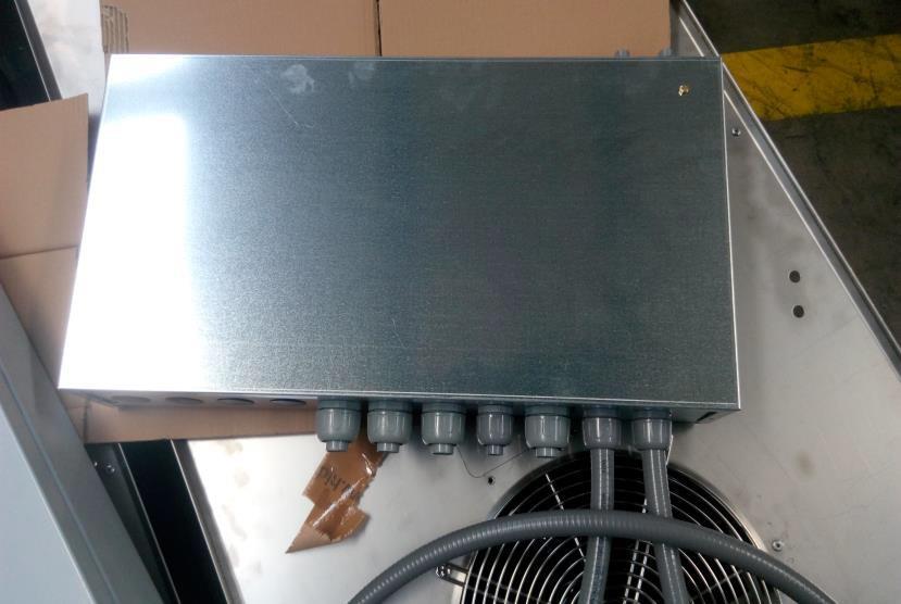
7 GBF ESK GBF1200ESK Once the front control panel and the electrical box is mounted and all of the power and sensor cables are connected, per the correct wiring diagram, the holes must be sealed with foam and finished. Below are the photos of the electrical box, the terminal strips and connections. After removing the 6 screws that hold the top cover on, set it off to the side and you will see the 4 holes for securing the box to the top. Also the connections for the incoming power, 208/240VAC, 60hz, 1 PH are labeled L1 and L2, this is where the electrician will supply power. The ground will be connected to terminal #13 or #14. There will be a cord with 3 wires marked solenoid valve, this is for the field installed solenoid valve to allow the system to pump down and shut off once the air sensor is satisfied. 7


8 8

9 9
10 10
11 11
12 GBC440-TS EVAPORATING UNIT 12
13 13

14 14
15 15
16 16

17 17
18 18
19 19

20 GBC1200 EVAPORATING UNIT 20
21 21

22 NOTES Thermalrite th Avenue N, Suite 100 Plymouth, MN Every step of the way 22
LED REVEALS - INSTALLATION INSTRUCTIONS
 SEPTEMBER 2017 PAGE 1 Fry Reglet s Reveals are designed to be installed in conventional drywall construction and will accommodate board thickness. Standard installation is quick and easy similar to the
Mizer Single Pump and Starter Box
 Mizer Single Pump and Starter Box Table of Contents Line Diagram... 2 Overview... 3 Booster Pump Specifications... 3 Water... 3 Electrical... 3 Models... 3 Mounting... 4 Electrical... 6 Motor Rotation...
Instruction Sheet. Subject: Installations Instructions. Air Compressor Kits. Importan
 MULTIPLEX 2100 FUTURE, SELLERSBURG, IN 47172 800-367-4233 WWW.MANITOWOCBEVERAGE.COM/US Instruction Sheet Subject: Installations Instructions Importan Read the following warnings before beginning an installation.
ETF-600 Sensor Operated Lavatory Faucet
 INSTALLATION INSTRUCTIONS OPTIMA SYSTEMS SENSOR OPERATED LAVATORY FAUCET ETF-600 I.I. Code No. 0816318 ETF-600 Sensor Operated Lavatory Faucet Includes Instructions for Installation of Optional Back Checks
SolarSheat Wall Installation Manual
 SolarSheat Wall Installation Manual Version 1.5 April 23, 2013 Copyright 2013 Your Solar Home, All Rights Reserved SolarSheat products must be installed in accordance to all local building, plumbing, electrical,
SolarSheat Wall Installation Manual
 SolarSheat Wall Installation Manual Version 3.2 December 15, 2015 Copyright 2015 Your Solar Home, All Rights Reserved SolarSheat products must be installed in accordance to all local building, plumbing,
FLUSH MANIFOLD REFERENCE MANUAL FOR LIQUID LAUNDRY SUPPLY SYSTEMS. FM-500 Series. P/N Rev. C
 FLUSH MANIFOLD FOR LIQUID LAUNDRY SUPPLY SYSTEMS REFERENCE MANUAL FM-500 Series DESCRIPTION Figure 1.0a Description, Standard Flush Valve Water Inlet Pipe Tee Solenoid Valve Flow Switch Hose Barb (for
TDR Cold Air Intake for the NC
 TDR Cold Air Intake for the NC Year: Models: TDR-CAI-NC Thank you for purchasing the Track Dog Racing Cold Air Intake for the NC. The Cold Air Intake is designed with and very efficient K&N Filter and
Control Panel Interface Upgrade Installation Guide For Model 200i and 250i Motorcycle Dynamometers Serial Number 202xxxx.
 2004 Dynojet Research, Inc. All Rights Reserved. Control Panel Interface Upgrade Installation Guide For Model 200i and 250i Motorcycle Dynamometers Serial Number 202xxxx. This manual is copyrighted by
Ultra-Thin Recessed LED Light Installation Guide
 TM PROFESSIONAL GRADE LED LIGHTING www.aspectled.com Copyright 2012-2016. aspectled, Inc. 1 OVERVIEW aspectled s Ultra-Thin series of recessed lights are bright, energy efficient, attractively styled,
Trouble Shooting. Symptom Possible Cause Solution Power switch ON but switch Light is Off. Main power to unit Off. Switch light defective.
 Trouble Shooting TE: Should the OAM Purger shut down on a FAULT condition, DO T POWER OFF THE PURGER until you have first removed the electrical panel cover and recorded the status of the indicator LED
INTRODUCTION 2EZHM DESCRIPTION
 INTRODUCTION In order to achieve maximum production and reliability from this system, it is necessary to be familiar with its capabilities. Knowledge of installation, components and set up are essential
Kit Drain Water Tempering Kit
 Kit 90092 - Drain Water Tempering Kit for Models DH2000 and MD2000 Kit Parts: Refer to the parts list below to ensure all the parts necessary for the installation are in your kit. Item Part Description
Automated Wardrobe Lift Installation Instructions Standard
 Automated Wardrobe Lift Installation Instructions Standard 1 CONTACT PHONE - 704 746 3700 Tips for successful installation 1. When mounting the rotating arms, make sure you allow for the arms at the clothes
TABLE OF CONTENTS SPECIFICATIONS 3 INSTALLATION 4. Direct Mount 4. Ducted Installations 5. Installing Plenum 5. Machine Mount Stand 5.
 TABLE OF CONTENTS PAGE SPECIFICATIONS 3 INSTALLATION 4 Direct Mount 4 Ducted Installations 5 Installing Plenum 5 Machine Mount Stand 5 Ceiling Mount 6 Pedestal Stand 7 Drain Installation 7 Electrical 8
ChargePoint Gateway Installation Instructions
 ChargePoint Gateway Installation Instructions You must be a licensed electrician and complete online training (http://chargepointuniversity.netexam.com/) to become a ChargePoint Certified Installer, and
DCC-3000 Climate Control for Vintage Air GEN-IV systems
 INSTALLATION AND OPERATOR S MANUAL FOR DCC-3000 Climate Control for Vintage Air GEN-IV systems PARTS INCLUDED WITH THIS SYSTEM Vent sensor housings: 2 1 / 2 housings (x2) 2 housings (x2) Installation/operator
At-FST Series I N S TA L L AT I O N A N D O P E R AT I N G I N S T R U C T I O N S W W W. A I G I S M E C H. C O M
 FULL HEIGHT GALVANIZED STEEL TURNSTILE SINGLE UNIT 3 60 At-FST Series AT-FST SERIES I N S TA L L AT I O N A N D O P E R AT I N G I N S T R U C T I O N S W W W. A I G I S M E C H. C O M SAFETY PRECAUTIONS
GOG TOWER TOWER COUNTER SERIES
 GOG TOWER TOWER COUNTER SERIES RF GOG RF9 GOG RF12 GOG RF15 Double glazed, condensation free, glass on glass construction Sliding double glazed rear doors argon filled Deck forced refrigeration Double
Florham Park, NJ USA Call (ASCO) for sales or service
 for sales or service") Operator s Manual 7000 Series ATS Automatic Transfer Switches D design, 30 through 230 A DANGER is used in this manual to warn of a hazard situation which, if not avoided, will result in death or serious
Operator s Manual 7000 Series ATS Automatic Transfer Switches D design, 30 through 230 A DANGER is used in this manual to warn of a hazard situation which, if not avoided, will result in death or serious
30GX AIR-COOLED LIQUID CHILLER
 30GX-5SB 30GX080-265 AIR-COOLED LIQUID CHILLER PERFORMANCE DATA FIELD WIRING DIAGRAM 1998 Carrier Corporation Syracuse, New York 13221 Form 30GX-5SB Supersedes 30GX-4SB Printed in U.S.A. 5-98 Catalog No.
30GX AIR-COOLED LIQUID CHILLER
 30GX-4SB 30GX080-265 AIR-COOLED LIQUID CHILLER PERFORMANCE DATA FIELD WIRING DIAGRAM 1997 Carrier Corporation Syracuse, New York 13221 Form 30GX-4SB Supersedes 30GX-3SB Printed in U.S.A. 12-97 Catalog
Solenoid - Troubleshooting Guide
 Solenoid - Troubleshooting Guide LAST UPDATED: 09/19/2018 Introduction Page 1 of 12 pages Solenoid Valve Troubleshooting Make sure the machine receives the correct air pressure and flow. Make sure the
F-150 Super Crew W/Opening Console Installation
 2004-08 F-150 Super Crew 40-20-40 W/Opening Console Installation Step 1. Driver and Passenger Tops/DT&PT: All the parts of your seat cover are labeled inside. Use the Seat Cover Piece Identification Chart
PART 1 GENERAL. Pfannenberg Inc.
 PROJECT MANUAL GUIDE SPECIFICATIONS FOR: PFANNENBERG SERIES DTS COOLING UNITS FOR SIDE MOUNTING/DOOR MOUNTING TO ELECTRICAL ENCLOSURES AND INDUSTRIAL CONTROL PANELS PART 1 GENERAL 1.1 SUMMARY A. Cooling
Upgrading from Router to Spindle in the RBK Control Box
 SBG00375 Upgrading from Router to Spindle in the 10270 RBK Control Box Page -1- Upgrading from Router to Spindle in the 10270 RBK Control Box Overview - This document will walk you through the steps needed
Installation Instructions Table of Contents
 Installation Instructions Table of Contents Pre- Installation of Garage Storage Lift 2 Layout the Garage Storage Lift 3 Installing the strut Channels 3 Install the Drive Assembly 5 Install the Drive Shaft
ECO# 1801 REVISION# 000 ES DATE
 SmokeShield Elevator ECO# 1801 REVISION# 000 ES 10-458 DATE 08/25/2018 ECO# 1801 REVISION# 000 ES 10-458 DATE 08/25/2018 Section 1 Table of Contents Section 2 Safety Check List 2 Section 3 Freight Receiving
section-page Table 1. Transfer switching device ratings. Conditional short circuit current
 Operator s Manual 7000 Series ATS Automatic Transfer Switching Equipment D design 30 through 200 amperes TABLE OF CONTENTS section-page INSTALLATION... 1-1 Enclosures and Mounting... 1-1 Power Connections...
Installation Instructions
 Accessory Ultra-Violet Germicidal Lamps 40RM007-034, 40RMQ008-016 and 40RMS008-024 Air Handler Units Installation Instructions Part Numbers: CRDBLFIX001A00, CRDBLFIX002A00, CRDBLFIX003A00, CRDBLFIX004A00,
TECHNICAL DOCUMENT. PCNC Mill Enclosure Door Switch Kit. Installation
 PCNC Mill Enclosure Door Switch Kit Product Identification: Enclosure Door Switch Kit (PN 35550) Purpose: This document details installation and use of the Enclosure Door Switch Kit on either a PCNC 770
MODEL SCA Installation and Operation Manual Important:
 MODEL SCA Installation and Operation Manual Important: This manual contains specific cautionary statements relative to worker safety. Read this manual thoroughly and follow as directed. It is impossible
INSTALLATION INSTRUCTIONS COMMERCIAL ROOM VENTILATORS WITH EXHAUST. For Use with Bard 2 2-1/2 Ton Wall Mount T Series Heat Pumps
 INSTALLATION INSTRUCTIONS COMMERCIAL ROOM VENTILATORS WITH EXHAUST MODELS CRVMWH-3 For Use with Bard 2 2-1/2 Ton Wall Mount T Series Heat Pumps Bard Manufacturing Company, Inc. Bryan, Ohio 43506 Since
TA V TA V
 TA-3030 12V TA-3031 24V High Cooling Capacity Low Power Consumption Small Dimensions Low Weight Parallel Flow Condenser Aluminum Body ABS Acrylic Cover TA-3030 12V p.n. 4500-030 TA-3031 24V p.n. 4500-031
CENTRAL SLURRY SYSTEMS Model 911
 CENTRAL SLURRY SYSTEMS Model 911 Installation and Operating Instructions Revised 6/04/08 PRACTICAL SYSTEMS, INC. 11617 Prospect Road Odessa, FL 33556 (800) 237-8154 Fax (800) 330-3800 (727) 376-7900 Fax
E.S.P. Embedded Sensing Probes for Motor Brushes
 E.S.P. Embedded Sensing Probes for Motor Brushes 2/13 Installation & Operating Manual MN609 Any trademarks used in this manual are the property of their respective owners. Important: Be sure to check www.baldor.com
CENTRAL SLURRY SYSTEMS Model 915
 CENTRAL SLURRY SYSTEMS Model 915 Installation and Operating Instructions 08/02/18 PRACTICAL SYSTEMS, INC. 11617 Prospect Road Odessa, FL 33556 (800) 237-8154 Fax (800) 330-3800 (727) 376-7900 Fax (727)
2017 TigerStop, LLC. Installation Guide AUTOMATION. February 2017 Mk1
 2017 TigerStop, LLC Installation Guide AUTOMATION February 2017 Mk1 1 Sensor Clip Safety Box Kill Switch (attached) I/O Panel Controller Cable Sensor Bracket Locking Handles 2 pin connector w/ pigtail
BITZER Liquid Injection Guidelines for CSH Compressors
 BITZER Liquid Injection Guidelines for CSH Compressors Liquid Injection Additional cooling may be required during reduced capacity operation, high condensing and / or low evaporating temperatures. Direct
MDG25PRAWW0 : 01 - TOP AND CONSOLE PARTS [1/6]
![MDG25PRAWW0 : 01 - TOP AND CONSOLE PARTS [1/6]](/thumbs/94/122284254.jpg "MDG25PRAWW0 : 01 - TOP AND CONSOLE PARTS [1/6]") MDG25PRAWW0 : 01 - TOP AND CONSOLE PARTS [1/6] Page 1 of 12 MDG25PRAWW0 : 01 - TOP AND CONSOLE PARTS [1/6] Ref # Part Number Qty. Description 1 W10135154 Installation Instruction 1 W10313706 INSTALLATION
MDG25PRAWW0 : 01 - TOP AND CONSOLE PARTS [1/6] Page 1 of 12 MDG25PRAWW0 : 01 - TOP AND CONSOLE PARTS [1/6] Ref # Part Number Qty. Description 1 W10135154 Installation Instruction 1 W10313706 INSTALLATION
Installing Your 220v J-POD Kit
 Installing Your 220v J-POD Kit NOTE: There are two J-POD versions depending on your pump voltage - 110 volt and 220 volt. MAKE SURE YOU HAVE THE RIGHT VOLTAGE J-POD FOR YOUR. Using software and hardware
CURVED CC5 CC5 RF6 CC5 RF9 CC5 RF12 CC5 RF15 CC5 HT6 CC5 HT9 CC5 HT12. Page 1. Download C.A.D models or contact us on COSSIGA.COM
 CURVED CC5 RF CC5 RF6 CC5 RF9 CC5 RF12 CC5 RF15 Deck forced refrigeration Sliding doors front and rear Double glazed Two adjustable shelves Ticket strips on shelves and deck Undershelf and canopy LED lights
ELECTRICAL SYSTEM UPGRADE
 NEW CONTROLLER & ELECTRICAL SYSTEM UPGRADE FOR DAIRY TECH, INCORPORATED 10, 30 & 60G PASTEURIZERS Parts to Include 2 Wire ties (Nuts) 2 sticky wire mount pads Large Rubber Grommet (for bottom of electric
CURVED CC5 CC5 RF6 CC5 RF9 CC5 RF12 CC5 RF15 CC5 HT6 CC5 HT9 CC5 HT12. Page 1. Download C.A.D models or contact us on COSSIGA.COM
 CURVED CC5 RF CC5 RF6 CC5 RF9 CC5 RF12 CC5 RF15 Deck forced refrigeration Sliding doors front and rear Double glazed Two adjustable shelves Ticket strips on shelves and deck Undershelf and canopy LED lights
Florham Park, NJ USA Call (ASCO) for sales or service
 for sales or service") Operator s Manual 4000 Series ATS Automatic Open-Transition Transfer Switches D design 30 230A, J design 260 600A, H-design 800 1200A, G-design 1600 4000A, F-design 4000A DANGER is used in this manual
Operator s Manual 4000 Series ATS Automatic Open-Transition Transfer Switches D design 30 230A, J design 260 600A, H-design 800 1200A, G-design 1600 4000A, F-design 4000A DANGER is used in this manual
Water to Water Geothermal Heat Pump 3-Phase Models Both 208 & 480
 Installer Water to Water Geothermal Heat Pump 3-Phase s Both 208 & 480 Installation Instructions : THA-***-2 (208, 3-Phase) THT-***-2 (208, 3-Phase) THA-***-3 (480, 3-Phase) THT-***-3 (480, 3-Phase) This
VLH 504 to Air-to-Water Reverse Cycle Heat Pumps. 126 to 294 kw. 133 to 307 kw
 Air-to-Water Reverse Cycle Heat Pumps VLH 504 to 1204 126 to 294 kw 133 to 307 kw Technical Brochure TM VLH-N.3GB Date : June 2005 Supersedes : TM VLH-N.2GB/07.04 Specifications Advantages Range extension
Installation & Operations Manual
 Sustainable Solutions to Hard Water Installation & Operations Manual SB-250, SB-350, SB-450 & SB-650 3/15 Commercial Electronic Descaler 115/230 VAC (Auto Selected) Sustainable Solutions to Hard Water
FULL HEIGHT ALUMINUM TURNSTILE DOUBLE UNIT AT-FAL SERIES I N STALLATION AND O P E RATING I N STRUCTIONS
 FULL HEIGHT ALUMINUM TURNSTILE DOUBLE UNIT AT-FAL SERIES I N STALLATION AND O P E RATING I N STRUCTIONS CONTENTS 1. SITE PREPARATION 2. EXPLODED VIEW DRAWING 3. UNPACKING 4. SPECIFICATIONS 5. INSTALLATION
INSTALLATION INSTRUCTIONS FOR EGA AND EGH SERIES ELECTRIC HEATERS IN V OR H SERIES UNITS
 INSTALLATION INSTRUCTIONS FOR EGA AND EGH SERIES ELECTRIC HEATERS IN V OR H SERIES UNITS NOTE TO INSTALLER The words SHALL and MUST indicate a requirement which is essential to satisfactory and safe product
Woda-Sci System Installation Parts Set
 Installation Manual Woda-Sci System Installation Parts Set 5/32 x 3 ½ Drill Bit - 5 Connector Body - 7 3/8 Locking Nut - 8 3/16 x 1 ¼ Concrete Anchors- 4 Mounting Screws - 3 Stainless Steel Hanger - 9
INSTALLATION AND OPERATION INSTRUCTIONS 4400QC SERIES POWER PAKS
 INSTALLATION AND OPERATION INSTRUCTIONS 4400QC SERIES POWER PAKS MODELS 4400QC Series 4404QC 4410QC 4414QC 4420QC C US IMPORTANT INFORMATION To register your product, visit our web site at www. perlick.com.
SHIVVERS ROTATION DETECTOR. fshiwersf ROTATION DETECTOR 676A-001A
 SHIVVERS ROTATION DETECTOR 676A-1A INSTALLATION & OPERATING INSTRUCTIONS fshiwersf ROTATION DETECTOR 676A-1A INDICATOR LIGHT Solid Red = Rotation Is OK Slow Flash (1 sec. on; 1 sec. off)= Rotation Detector
Torque Test Stands Series TS MODELS TST / TSTH & TSTM / TSTMH. User s Guide
 MODELS TST / TSTH & TSTM / TSTMH User s Guide Thank you Thank you for purchasing a Mark-10 Series TS Torque Measurement Test Stand. We are confident that you will get many years of great service from this
Center Mount Unit Coolers
 LK-CMTB JAN 2018 Replaces LK-CMTB JULY 2017 Center Mount Unit Coolers Technical Guide s ACM Air Defrost ECM Electric Defrost Table of Contents Nomenclature 2 Features & Benefits 3 Performance Data 4 Specifications
12 CB30M SERIES UNITS INCLUDING ECB29 ELECTRIC HEAT
 Service Literature Corp. 9711 L7 CB29M CB30M ELITE 10 CB29M and ELITE 12 CB30M SERIES UNITS INCLUDING ECB29 The Elite 10 CB29M and Elite 12 CB30M are high efficiency blower coils. Several models are available
ThermoLite 26W Solar Panel Installation Instructions
 ThermoLite 26W Solar Panel Installation Instructions WARNING: Always wear safety glasses and protective gloves when working with batteries. SB Unit Installation 3. Attach adapter bracket (401271) to solar
ACCESSORY KIT INSTALLATION INSTRUCTIONS
 ACCESSORY KIT INSTALLATION INSTRUCTIONS GAS HEAT KIT FOR -60 F OPERATION KIT MODELS 2BC04700106, 2BC04700151 and 2BC04700154 FOR SINGLE PACKAGE AIR CONDITIONERS 6.5 THRU 12.5 TONS MODELS DM, DL, J**DM,
LPT50BRD (8x11x3 Enclosure)
") LPT50BRD (8x11x3 Enclosure) TROUBLESHOOTING AND REPAIR MANUAL ALL REPAIRS SHOULD BE PERFORMED BY A QUALIFIED ELECTRICIAN The LPT50BRD is a field repairable switch. Warranty covers defective parts only.
LPT50BRD (8x11x3 Enclosure) TROUBLESHOOTING AND REPAIR MANUAL ALL REPAIRS SHOULD BE PERFORMED BY A QUALIFIED ELECTRICIAN The LPT50BRD is a field repairable switch. Warranty covers defective parts only.
ON DEMAND INSTALLATION GUIDE
 ON DEMAND INSTALLATION GUIDE PICTOGRAMS Each Signifier displayed here is specific to this User Manual. Menu Previous Advance Note Tip Example Barcode Scanner Rotary Heads Drum & Frame Pump Stations Control
Transducer/Cable Assembly. Model IN64108 August 1997 Applicable additional manuals: IN64035 INSTALLATION INSTRUCTION. Installation Instruction
 Aerospace Group Conveyance Systems Division Carter Brand Ground Fueling Equipment IN64108 August 1997 Applicable additional manuals: IN64035 INSTALLATION INSTRUCTION Installation Instruction Transducer/Cable
Please Read The Entire Bulletin Before Proceeding
 Bulletin # 122 Fast Fold SEW Motor Retro Page 1 of 21 Summary Products Affected Key Word Tags Tools/Equipment (If Required) Parts/Materials (If Required) Related Media Fast Fold USEM to SEW Eurodrive Retrofit
FOR OT/HT MODEL CHILLERS STYLE B AND C CONTROL CENTERS , AND
 LOW PRESSURE CUTOUT CONTROL P/N 025-45742-000 INSTALLATION AND MAINTENANCE Supersedes: 160.43-NM4 (1206) Form 160.43-NM4 (1112) 035-21593-000 FOR OT/HT MODEL CHILLERS STYLE B AND C CONTROL CENTERS 366-70488,
ILLUSTRATED PARTS LIST
 Anoka, MN. 0- Telephone -00--00 Facsimile -00--0 FCB POST-MIX DISPENSER WITH HOT-GAS DEFROST AND V ELECTRONICS (DEFROST/ERROR INDICATOR LIGHTS) UNIT PART NO. 0000 000 THIS DOCUMENT CONTAINS IMPORTANT INFORMATION
Model 579 Curtain Machine Manual. General Information. Unpacking:
 Model 579 Curtain Machine Manual. General Information The Model 579 curtain machine is designed for use with most light duty commercial and residential drapery tracks. The 579 curtain machine is designed
THINK COLD. THINK LARKIN. WAREHOUSE/INDUSTRIAL UNIT COOLER
 Bulletin LH-02 August 2002 (Replaces LH-98, March 1998) THINK COLD. THINK LARKIN. WAREHOUSE/INDUSTRIAL UNIT COOLER Warehouse/Industrial Unit Coolers Larkin introduces it s latest line of warehouse/industrial
Demand Switch NEFA20 Plus. Installation Guide. Please read this entire guide before beginning the installation!
 Demand Switch NEFA20 Plus Installation Guide Please read this entire guide before beginning the installation! Supplied Parts Protective Covers DIN Mounting Rail NEFA20 Plus Mounting Rail Spacer Warning
600 D 220 E 230 J Hanover Road, Florham Park, New Jersey USA For sales or service call (ASCO)
") Operator s Manual Series 386 Electrically Operated Non Automatic Switches J design 600 amps DANGER is used in this manual to warn of high voltages capable of causing shock, burns, or death. WARNINGisusedinthismanualtowarn
Operator s Manual Series 386 Electrically Operated Non Automatic Switches J design 600 amps DANGER is used in this manual to warn of high voltages capable of causing shock, burns, or death. WARNINGisusedinthismanualtowarn
Rated for use on 110/120VAC 60Hz and 220/240VAC 60Hz applications
 WPC1-XXXX-T Rated for use on 110/120VAC 60Hz and 220/240VAC 60Hz applications Installation Instructions: Read these instructions in their entirety before performing any installation work. FOR USE WITH
Upgrading the Sure Coat Modular Gun Control System
 Instruction Sheet P/N 007365B Upgrading the Sure Coat Modular Gun Control System WARNING: Read the Safety section in the Sure Coat Modular Gun Control System manual before performing any of the following
HVAC Motors Three Phase, TEFC, Foot Mounted, with Internal AEGIS
 1 1 1/2 2 3 5 7 1/2 230/460 Volt HVAC TEFC, Foot Mounted, with Internal AEGIS 1 thru 100 56 thru 405T Bearing Protection Ring 10 15 20 25 30 40 50 3600 56 EM3545-G 773 K 12.23 33 77 230/460 1.4 143T EM3546T-G
Australian Wiring Instructions:
 Australian Wiring Instructions: Generator/Switch Wiring: Remove the generator controller fascia and identify wire #44 going to the circuit breaker in the external connection box, this wire is the active
Graf Aqua Controller Programming & Setup to use with 3- way valve for backup systems
 Graf Aqua Controller Programming & Setup to use with 3- way valve for backup systems Back-up System Overview The Graf Aqua Control and Three way valve combined will automate the operation of a backup water
Installation Instructions
 NOTE: Read the entire instruction manual before starting the installation. This symbol indicates a change since the last issue. SAFETY CONSIDERATIONS Installing and servicing air conditioning equipment
INSTALLATION INSTRUCTION MANUAL
 INSTALLATION INSTRUCTION MANUAL LED FLOOD LIGHT, 100-277VAC MODELS: SL923FLF-15W; SL923FLF-30W; SL923FLF-50W; SL923FLF-80W; SL923FLF-100W; SL923FLF-150W; SL923FLF-300W Model number parameter list: Model
MODELS DSH/KSH/DSV/KSV R-410A LOW-AMBIENT KIT
 MODELS DSH/KSH/DSV/KSV R-410A LOW-AMBIENT KIT Supersedes Form145.10-IOM1 (810) Form 145.10-IOM1 (910) LOW-AMBIENT KIT MODELS DSH/KSH/DSV/KSV R-410A AIR CONDITIONING UNITS INSTALLATION INSTRUCTIONS IMPORTANT!
Coil Data Nominal Current MA Nominal VA Sealed. Coil Data Nominal Current MA Nominal VA Sealed. Single Pole Double Throw (SPDT)
") 14/03/08 A136 Relay - General Purpose 90-293Q Enclosed fan relays used for switching single or two speed fan motors, solenoids, relays, resistive loads, heating and cooling applications and general purpose
14/03/08 A136 Relay - General Purpose 90-293Q Enclosed fan relays used for switching single or two speed fan motors, solenoids, relays, resistive loads, heating and cooling applications and general purpose
Shaver Industries. Assembly Instructions Motorized Vertical Vinyl Curtain Door
 Shaver Industries 20 Steckle Place, Kitchener, ON N2E 2C3 Ph 1(888) 766 8328 www.shaverinc.com Assembly Instructions Motorized Vertical Vinyl Curtain Door System Overview: Your Shaver's Motorized Vertical
TABLE OF CONTENTS INTRODUCTION 3. INSTALLATION PROCEDURES Air Conditioner Location 4. A/C Ducting Installation 5
 585474 1 TABLE OF CONTENTS SECTION PAGE INTRODUCTION 3 INSTALLATION PROCEDURES Air Conditioner Location 4 Air Conditioner Mounting 4 A/C Ducting Installation 5 Power Kit Installation (Batteries). 5 Separator...
Therm-L-Tec Building Systems LLC. Therm-L-Tech. Power Operated Retrofit Kit 230 VAC or 440/480 VAC 50/60 Hz Installation and Setup Manual
 Therm-L-Tec Building Systems LLC Therm-L-Tech Power Operated Retrofit Kit 230 VAC or 440/480 VAC 50/60 Hz Installation and Setup Manual Rev. A 01/2015 Index Index 1 Electrical Requirements for Therm-L-Tec
INSTALLATION INSTRUCTIONS FUEL SURGE TANK KIT
 INSTALLATION INSTRUCTIONS FUEL SURGE TANK KIT BMW E46 3-Series, Excl Convertible Document: 19-0056 Support: info@radiumauto.com Relieve fuel pressure in vehicle before beginingthe installation. Disconnect
Installation Instruction
 T F W 604.549.9379 604.549.9555 fluxwerx.com Installation Instruction DRIVER ENCLOSURE Ceiling Type Version Grid Battery Pack GRID MOUNT INSTALL OPTIONS OPTION 1: Standard Vertical Grid drivers can be
QUANTUM SERIES JUICE DISPENSER
 QUANTUM SERIES JUICE DISPENSER l IPL Manual Release Date: April 25, 2001 Publication Number: 720901120IPL Revision Date: April 28, 2014 Revision: C Visit the Cornelius web site at www.cornelius.com for
COMMERICAL SPLIT SYSTEM KITS AND ACCESSORIES /2014 Supersedes 8/2012
 COMMERICAL SPLIT SYSTEM KITS AND ACCESSORIES 506953-01 3/2014 Supersedes 8/2012 Litho U.S.A. MSAV Supply Air Blower VFD Kit INSTALLATION INSTRUCTIONS FOR MSAV (MULTI-STAGE AIR VOLUME) SUPPLY AIR BLOWER
TBS100FC CASE SEALER DESCRIPTION AND SET UP PROCEDURES
 INTRODUCTION In order to achieve maximum production and reliability from this system, it is necessary to be familiar with its capabilities. Knowledge of installation, components and set up are essential
CSA CERTIFIED Conforms to UL 507
 Installation tion Instructions Please read and save these instructions! TURBO/MAXX12 Volt All Weather RV Ventilator Fans P/N 00-965001 Deluxe Model 1200T WITH THERMOSTAT P/N 00-965007 Standard Model 3550
Use and Care Guide. Part # UC SV-D Model # UC SV-d UC SV-d
 Part # UC-12-5-930-SV-D Model # 53502111 UC-18-9-930-SV-d 53503111 UC-24-12-930-SV-d 53504111 Use and Care Guide BEM DJUSTBLE LED UNDER CBINET LIGHT WITH MGN MOUNT INSTLLTION OPTION Questions, problems,
Power Operated Retrofit Kit for Manual Door 230 VAC or 440/480 VAC 50/60 Hz Installation and Setup Manual
 Therm-L-Tec Building Systems LLC Therm-L-Tech Power Operated Retrofit Kit for Manual Door 230 VAC or 440/480 VAC 50/60 Hz Installation and Setup Manual Rev. A 10/2014 Index Index 1 Electrical Requirements
Model 2300JL Installation Guide
 Model 2300JL Installation Guide POWER ACCESS CORPORATION 4 HERSHEY DRIVE, DOCK 4 ANSONIA, CT 06401 800-344-0088 WEBSITE: www.power-access.com EMAIL: salesinfo@power-access.com 1 STANDARD PARTS MODEL 2300JL
Access Riser Fits PRO370 and PRO380 Series
 Installation Manual 7171000D Access Riser Fits PRO370 and PRO380 Series Contents 1.) General Information 2.) Installation 3.) Optional 2 Installation Kits 4.) Typical Installation Diagram 5.) Junction
INSTALLATION INSTRUCTIONS COMMERCIAL ROOM VENTILATORS WITH EXHAUST. For Use with Bard CH Series 3, 4, & 5 Ton Wall Mount Heat Pumps
 INSTALLATION INSTRUCTIONS COMMERCIAL ROOM VENTILATORS WITH EXHAUST MODEL CHCRV-5 For Use with Bard CH Series 3, 4, & 5 Ton Wall Mount Heat Pumps Bard Manufacturing Company, Inc. Bryan, Ohio 43506 Since
Prodigy Eclipse ECC, EH330 and EH430 C or D Service Parts
 This part list contains the service parts for the Eclipse 00, 00, and 800 systems. D series models began early 0 The models that are covered include: EH0 C & D EH0 C & D ECC00 ECC00 ECC800 Contents Head
Model 2300DL Installation Guide
 Model 2300DL Installation Guide POWER ACCESS CORPORATION 4 HERSHEY DRIVE, DOCK 4 ANSONIA, CT 06401 800-344-0088 WEBSITE: www.power-access.com EMAIL: salesinfo@power-access.com 1 STANDARD PARTS MODEL 2300DL
MICROPROCESSOR CONTROL WATER SUPPLY SYSTEM (MPR-01AW)
") MICROPROCESSOR CONTROL WATER SUPPLY SYSTEM (MPR-01AW) Installation, Operation, and Maintenance Manual REV. "B" REV. "C" PLEASE READ ENTIRE DOCUMENT BEFORE PROCEEDING WITH INSTALLATION Energy Saver has
MICROPROCESSOR CONTROL WATER SUPPLY SYSTEM (MPR-01AW) Installation, Operation, and Maintenance Manual REV. "B" REV. "C" PLEASE READ ENTIRE DOCUMENT BEFORE PROCEEDING WITH INSTALLATION Energy Saver has
INSTALL GUIDE AMBIENT BLINDS WINDSOR WIRE GUIDED SEMI RESTRAINED
 AMBIENT BLINDS WINDSOR WIRE GUIDED SEMI RESTRAINED INSTALL GUIDE CONTENTS September 2013 This manual is to be read in conjunction with the Product Specifications & Assembly manual SECTION NO. DESCRIPTION
MODEL CMA-44 PARTS MANUAL Rev 2.13
 MODEL CMA-44 PARTS MANUAL Rev 2.13 CMA DISHMACHINES 12700 KNOTT AVENUE GARDEN GROVE, CALIFORNIA 92841 800-854-6417 FAX 714-895-2141 www.cmadishmachines.com Table of Contents CMA-44 1. PARTS MANUAL... 4
TS Series TS Series
 TAC 1354 Clifford Avenue P. O. Box 2940 Loves Park, IL 61132-2940 www.tac.com TS-6700-850 Series TS-5700-850 Series Electronic Remote Temperature Sensors General Instructions APPLICATION Electronic thermistor
Replacing the Gear Drive Motor Assembly and GFCI Module for Operation with the Chain Drive Motor Assembly
 Replacing the Gear Drive Motor Assembly and GFCI Module for Operation with the Chain Drive Motor Assembly Kit Contents B00009035-3 Motor Drive Assembly (Return original to CMI) B00007698-8 GFCI Module
ANZI Transfer Switch and Generator Wiring Installation Addendum
 ANZI Transfer Switch and Generator Wiring Installation Addendum Reference all appropriate documentation. NOT INTENDED FOR USE IN CRITICAL LIFE SUPPORT APPLICATIONS. THIS PRODUCT CAN BE INSTALLED BY THE
AMEREC STEAMBATH GENERATOR (MODEL: AV2, 2KW/120 VOLT) SAVE THESE INSTRUCTIONS
 SAVE THESE INSTRUCTIONS") WARNING Electrical grounding is required on all AMEREC steambath generators. All electrical supplies should be disconnected when servicing generator. All wiring must be installed by a licensed electrical
WARNING Electrical grounding is required on all AMEREC steambath generators. All electrical supplies should be disconnected when servicing generator. All wiring must be installed by a licensed electrical