ORDER ON-LINE /
|
|
|
- Nickolas Fox
- 5 years ago
- Views:
Transcription

1 NM343 EXTERNAL SYSTEM FOR TRUCKS AND BUSES INSTALLATION MANUAL VERSION ORDER ON-LINE /
2
3 IMPORTANT Installation requires an experienced mechanic with knowledge of tools and equipment identified in this manual. Installation, disassembly, repairs and maintenance must be performed by an Authorized Installer. Authorized Installer must use proper protective equipment such as safety glasses and gloves when installing the system. Improper installation or use of unauthorized parts can cause malfunctions, loss of tire pressure or other consequences, which may result in serious injury or death. Manufacturer or Distributor will be not responsible for injuries resulting from misuse of equipment, use contrary to operating instructions of this manual or installation by any person other than an Authorized Installer. Information contained in this manual is subject to change. Col-Ven S.A. reserves the right, without notice, to make changes in equipment design or components as progress in engineering, manufacturing or technology may warrant. World-wide Patents VIGIA is a trademark of Col-Ven S.A.
4 TABLE OF CONTENTS 1 - VIGIA Automatic Tire Pressure System Features - Operation System Components Rotor mountings A) Disks 2 B) Stars 5 C) Threaded caps 7 D) Brackets for Steering Wheels Rotor Installation Procedure Tire valves Installation Procedure 8 Connecting valves to rotor Body couplings Installation Procedure 11 A) Steering axles 12 B) Non-steering axles with fenders 12 C) Non-steering axles without fenders 13 Connection between body couplings and rotor Hose Installation Procedure 22 General diagram 23 Connection procedure 23 Coupling between tractor and trailer Air Filter Purpose Location Installation Procedure Control and Display Modules Control Module NM Display Module NM Pneumatic and Electrical Connections 35 4 Tire Pressure Calibration Final system testing (in operation) Recommendations to the installer Failure location guide 39
5 1 - VIGIA AUTOMATIC TIRE PRESSURE SYSTEM Features: It allows for constant and automatic monitoring and adjustment of tire pressures. The system maintains a predetermined cold pressure, even in a moving vehicle or a vehicle with punctured tires. The VIGIA NM343 display module generates digital information on the status of tire pressures and system that is transmitted via its interface to the existing vehicle s satellite module and ultimately to the user s telematics software. Operation: In the event of a 3 or higher PSI decrease in the pre-established pressure in one or more tires due to punctures or other causes, the system automatically generates audio and visual signals that inform the driver of the problem and its location. At the same time the system begins pumping air, keeping tire pressures calibrated at the pre-set levels. If the loss of air is substantial, as in the case of a blow-out, and the equipment is not able to compensate for this loss, a visual signal advises the driver. At the same time, an electronic security mechanism blocks the equipment, stopping the system from pumping air, thus ensuring the normal operation of the other airdriven systems: brakes, suspension, etc. Model NM343 can be installed in all vehicles equipped with an air compressor. System components, operation and installation procedure are described in the following sections. 1
 DISKS To install the disks, replace nuts or bolts in the hub with Vigia stud bolts according to the Table in next page (Fig. 1).")
6 2 - SYSTEM COMPONENTS ROTOR MOUNTINGS VIGIA provides different rotor mountings for different hub types. A) DISKS To install the disks, replace nuts or bolts in the hub with Vigia stud bolts according to the Table in next page (Fig. 1). Vigia stud bolts are available for different thread sizes and lengths. Figure 1 One of the disk's faces has dash lines identified by numbers in the outer edge. These lines will be used for drilling and centring (Fig. 2). Figure 2 2
7 INSTALLATION PROCEDURE 1- Determine the quantity of nuts or bolts in the hub. 2- Assign a number to each one, # 1 corresponding to the one in the highest position, numbering the rest clockwise. The following table shows all possible hub clamp nut or bolt quantities in the first column. With this information, determine the necessary stud bolt quantity (column 2), the nuts or bolts to be replaced (column 3) and the disk lines to be drilled (column 4). Hub nuts or bolts - quantity Stud bolt quantity Nut or bolt numbers to be replaced Disk lines to be drilled * * * *Note: If the hub has 0.8 mm or 5/16" bolts and ornamental cap, 4 stud bolts must be used. 3- Replace the nuts or bolts specified in column 3 of the above table by the stud bolts provided with the system. 4- With a compass, measure clockwise the distance between the centre of the stud bolt replacing the bolt or nut assigned # 1, and the centre of the next stud bolt. 5- Mark that measurement on the disk to be used, onto the lines given in column 4 in Table 1, carefully placing one of the compass' ends in lines 0 or Repeat steps 4 and 5 as many times as necessary until all points to be drilled have been marked. All the selected drill points must be located at the same distance from the disk's outer edge. If the distance measured with the compass falls in between two points, mark a third point between the other two points, maintaining the original distance. 7- Drill the selected points with a 0.5 mm (13/64") bit first, and then with a mm (13/32") bit. 3

8 DISK FASTENING EXAMPLE An axle with a 10-nut hub is shown. The fastening nuts are numbered as specified in step 2 (Fig. 3). Figure 3 From Table 1, it is determined that for a 10-nut hub, 3 stud bolts should be used to replace nuts numbers 1, 4 and 8, which must be taken out and replaced with the stud bolts provided with the system (Fig. 4). Figure 4 The distance between the centre of the stud bolt that replaced nut # 1 and the centre of the next stud bolt is measured (Fig. 5). Figure 5 4
.")
9 In this example, Table 1 shows that the dashed disk lines to be used are numbers 0, 4, 4. Therefore, with the centre on a point on line 0, the rest of the points are placed on lines 4, obtaining three reference points at the same distance from the disk's outer edge (Fig. 6). Figure 6 The selected points are drilled, fastening the disk to the stud bolts with the washers and nuts provided (Fig. 7). Figure 7 B) STARS This element can replace the disks in units whose hubs have 3, 6, 9, 12, or 15 fastening nuts or bolts. Three of the nuts or bolts must be replaced by Vigia stud bolts that are provided with the system (Fig. 8). Vigia stud bolts are available for different thread sizes and lengths. Figure 8 5
10 INSTALLATION PROCEDURE 1- Determine the quantity of nuts or bolts in the hub. 2- Assign a number to each one, with # 1 corresponding to the one in the highest position; continue clockwise numbering the rest (Fig. 9). The following table shows all possible hub clamp nut or bolt quantities in the first column. With this information, determine which nuts or bolts will be replaced. Fig. 9 Hub nuts or bolts quantity Nut or bolt numbers to be replaced Replace the nuts or bolts specified in the second column of the table by the stud bolts provided with the system (Fig. 10). Fig With a compass, measure the distance between the centres of two stud bolts (Fig. 11). 6 Fig. 11

 bit first, and then with a 10.25 mm (13/32\") bit. Fasten the star to the stud bolts with the washers and nuts provided (Fig. 13). Fig.")
. A 2- Secure the provided VIGIA threaded cap in place.")
11 5- Apply the measurement to two of the star spokes, marking the points. Then, using one of the marked points as a reference, apply the measurement to the third spoke (Fig. 12). Fig. 11 The selected points must be located at the same distance from the star's outer edge. Fig. 12 If the distance measured with the compass falls in between two points, mark a third point between the other two points, maintaining the original distance measurement. 6- Drill the selected points with a 0.5 mm (13/64") bit first, and then with a mm (13/32") bit. Fasten the star to the stud bolts with the washers and nuts provided (Fig. 13). Fig. 13 C) THREADED CAPS This element is used in units with a threaded cap hub. INSTALLATION PROCEDURE 1- Take the original threaded cap out (in models with oil, first collect the oil in a clean container). A 2- Secure the provided VIGIA threaded cap in place. It must be the one specific to the unit. The model with a central hole is for units carrying oil. Replace the oil through the central hole in the threaded cap. Install the plug (A). 3- Put the disk or star in place, fastening it with the stud bolts, nuts or bolts provided. 7
 The rotor's purpose is to allow air to pass from a stationary point on the truck body to the rotating tires.")
 Hose and Tire valve 50 cm (Fig.")
12 D) BRACKETS FOR STEERING WHEELS Various rotor mounting kits for steering axles are available. Do not remove original lug nut form wheel. Always attach the bracket over the wheel nut with the provided nut ROTOR (Fig. 23) The rotor's purpose is to allow air to pass from a stationary point on the truck body to the rotating tires. Fig. 23 INSTALLATION PROCEDURE The rotor must be tightened with moderate torque, approximately 6 Lb./Ft. (Fig. 24). Note: The rotor output terminals must be oriented towards the inflation valves. Fig TIRE VALVES VIGIA offers different tire valves. All tire valves have a check valve at their brass end preventing air to escape from the tire. a) Hose and Tire valve 50 cm (Fig. 25): for inside tires in dual-tire configurations. b) Hose and Tire valve 30 cm: for outside tires in dualtire configurations or for single tires. Fig. 25 8
 1- Thoroughly clean the external thread of the original tire valve, preferably with a threading tool. 2- Remove the original valve core.")

13 Outside tires require the Outside tire connector U (Fig. 26) Single tires require the Outside tire connector L (Fig. 27) Fig. 26 Fig. 27 INSTALLATION PROCEDURE (Fig.28) 1- Thoroughly clean the external thread of the original tire valve, preferably with a threading tool. 2- Remove the original valve core. 3- Screw on the Outside tire connector, if required, lightly tightening it with a wrench. 4- Screw on the VIGIA valve, lightly tightening it with a wrench. 5- Ensure that the tire pressure is lower than the desired calibrated tire pressure. VIGIA hose and tire valves must not rub against the wheel rims and/or hubs. Important: Remove any tire extensions. Fig. 28 CONNECTING TIRE VALVES TO ROTOR 1- Insert the Nipples for Rotor (Fig. 29) to the VIGIA rotor and torque to approximately 2 Lb./Ft. (Fig. 30). Fig. 29 Fig. 30 9
 to the Nipples for Rotor and torque to approximately 1 Lb./Ft. (Fig.")


14 2- Screw the End Hose Connectors (Fig. 31) to the Nipples for Rotor and torque to approximately 1 Lb./Ft. (Fig. 32). Fig. 31 Fig Extend tire valve hose to the rotor, making sure that it is not touching the rotor mounting, hub or wheel rim. Cut tire valve hose as shown in Figure 33 and push free end into End Hose Connector nipple. Fig. 33 For single tire, install a Plug for Rotor (Fig. 34) on the open rotor output. Fig


15 2.4 - BODY COUPLINGS VIGIA offers three models of body couplings (Fig. 34): a) Double outlet b) Standard c) Quick connect Fig. 34 All models include a spacer that can be placed either inside or outside the body, fender or other mounting part, depending on vehicle characteristics (Fig. 35). Fig. 35 INSTALLATION PROCEDURE VIGIA offers several body mounting attachments designed to prevent air hoses from extending beyond the vehicle's body, or to avoid perforating fenders, body or cabin (fig. 36). Make sure that the hose does not rub against the mounting, even in extreme situations. Fig


, and then with 10.25 mm (13/32\") bit. 5- Install the corresponding body coupling. Fig.")
 1- Using a plumb, mark a point 400 mm (15 ¾ ) in front of the axle and as close as possible to the edge of the fender or truck s body.")
16 A-STEERING AXLES 1- Align the steering wheels parallel to the truck s body. 2- Hold a plumb from the fender, so that the string's vertical line crosses the rotor's centre. 3- Mark a point 50 mm (2") from the plumb line, towards the back of the vehicle and as close as possible to the edge of the fender (Fig. 37). Before drilling, make sure that there are no obstructions inside the fender. If there are any obstructions, find an unobstructed spot as close as possible to the point originally marked. 4- Drill first with 5 mm bit (13/64"), and then with mm (13/32") bit. 5- Install the corresponding body coupling. Fig. 37 B- NON-STEERING AXLES WITH FENDERS B1. Single axles (Fig. 38) 1- Using a plumb, mark a point 400 mm (15 ¾ ) in front of the axle and as close as possible to the edge of the fender or truck s body. Before drilling, make sure that there are no obstructions inside the fender or body. If there are any obstructions, mark a new position as close as possible to the point originally marked. 2- Drill first with 5 mm bit (13/64") and then with mm (13/32") bit. 3- Install the corresponding body coupling. Fig

 and then with a 10.25 mm (13/32\") bit. 4- Install the double outlet body coupling. If coupling is under unloading doors, install a protecting visor.")
17 B2. Double axles (Fig. 40) Note: This procedure applies only when the air pressure in tires of both axles will be the same. If that is not the case, refer to the procedure for single axles. 1- Using a plumb, determine the centre line between the axles. 2- On the centre line, define a point at the approximate height of the tires, with respect to floor level. Before drilling, make sure that there are no obstructions inside the fender or body. If there are any obstructions, mark a new position as close as possible to the point originally marked. 3- Drill first with 5 mm bit (13/64") and then with a mm (13/32") bit. 4- Install the double outlet body coupling. If coupling is under unloading doors, install a protecting visor. C- NON-STEERING AXLES WITHOUT FENDERS An adjustable body coupling mounting pipe is provided for these axles (Fig. 44). Fig. 44 C1. Single axles (Fig. 45) 1- Find a bolt or hole in the chassis approximately 400 mm (15 ¾ ) in front of the tire's centre line, and at a height that will avoid any rubbing to the mounting pipe, even with the suspension working at load limit (Fig. 46). 13
.")


18 2- Take the selected bolt out. 3- Secure the body coupling mounting pipe with the bolt provided. Tighten with a torque of approximately 115 lbs/sqft. (Fig. 47). The body coupling mounting pipe must remain with the VIGIA hose's outlet hole facing down. Fig. 46 Fig. 47 Fig Install body coupling to the adjustable mounting pipe as indicated in Figure 48. Note that body coupling s spacer is removed. 5- Pass the required hose length through the hole and connect the body coupling. 6- Screw the mounting pipe end with 15 lbs/sqft. torque turning the hose at the same time to avoid strangling. 7- Adjust the length of the adjustable mounting pipe making sure that body coupling end is not exposed. Fix position with corresponding conic nut. 14


19 C2. Double Axles (Fig. 49) Note: This procedure is applied only if the air pressure in the tires in both axles is the same. If that is not the case, refer to the procedure for single axles. 1- Find a bolt or hole approximately midway between both axles, and at a height that will avoid any rubbing to the mounting pipe, even with the suspension working at load limit. Fig Take the selected bolt out. 3- Secure the body coupling mounting pipe with the bolt provided. Tighten with a torque of approximately 115 lbs/sqft. The body coupling mounting pipe must remain with the VIGIA hose's outlet hole facing down. 4- Install body coupling to the adjustable mounting pipe as indicated in Figure 48 above. Note that body coupling s spacer is removed. 5- Pass the required hose length through the hole and connect the body coupling. 6- Screw the mounting pipe end with 15 lbs/sqft. torque turning the hose at the same time to avoid strangling. 7- Adjust the length of the adjustable mounting pipe making sure that body coupling end is not exposed. Fix position with corresponding conic nut. 15

20 Optional Adjustable body coupling mounting pipe with Bolt NF 5/8 x 2 ½ Bored Ø 6.25 mm To be used when the Vigia hose would become strangled should the standard adjustable pipe is employed. Figure 51 shows installation and parts required for this mounting pipe. 1 X1414.A /4 hose fastening nut 2 X2433.A079-5 Adaptor 5/16 to 1/4 3 X9201.A024-7 Hose Vigia 143 Ø 1/4 4 X9402.A112-3 Bolt NF 5/8 x 2 ½ - Bored Ø 6.25mm Note: Adaptor 5/16 to 1/4 must be used with O ring X9601.A022-0 Fig
21 CONNECTION BETWEEN BODY COUPLINGS AND ROTOR a) Set Assembly (Fig. 52) Fig


22 1. Fully screw the tightening nut to the bend. 2. Insert the plastic washer as shown in the drawing. 3. Screw the bend into the rotor cover until the plastic washer makes contact with the rotor cover s end. 4. Screw the stainless steel spring to the bend s open end. The stainless steel spring has a bigger diameter on one end Use this end to connect to the bend. 5. Insert a second steel spring to the stainless steel pipe. Use the spring s smaller diameter end to connect to the stainless steel pipe. 6. Screw and tighten the nipple for body coupling to the body coupling. BODY COUPLING NIPPLE FOR BODY COUPLING 18

 longer than the stainless steel pipe; i.e. stainless steel 40 cm. (15 3/4 ), hose must be 76 cm. (29 15/16 ).")
23 7. Measure the stainless steel pipe length. To that end, position the assembled rotor cover and pipe as shown in the drawings below. Cut stainless steel pipe if necessary. NON STEERING AXLES STEERING AXLES CUT HERE CUT HERE When cutting the stainless steel pipe, use the appropriate tool to eliminate any sharp edges. 8. Cut the hose Push-Lok 36 cm. (14 3/16 ) longer than the stainless steel pipe; i.e. stainless steel 40 cm. (15 3/4 ), hose must be 76 cm. (29 15/16 ). 40 CM. 76 CM. 9. Insert one hose end to the nipple for body coupling. BODY COUPLING NIPPLE FOR BODY COUPLING HOSE PUSH-LOK 19


24 10. Pass the hose through the stainless steel pipe and screw the spring s free end to the body coupling. NIPPLE FOR BODY STANDARD BODY COUPLING 5/16 COUPLING SPRING 15 x 90 MM. - STAINLESS STEEL STAINLESS STEEL PIPE 60 CM. PUSH-LOK HOSEPIPE 11. Lubricate the hose s free end with silicone or similar product and pass it through the rotor cover assembly. 12. Insert the spring to the stainless steel pipe. Cut the hose at the mark with number


25 13. Screw the end hose connector to the rotor. 14. Insert the hose to the end hose connector. 15. Install the rotor cover and tighten its nut. 16. The rotor cover must remain parallel to the tire. Verify that the stainless steel pipe is not rubbing against the tire, or that it is not too far from the tire. Adjust by modifying the position of the bend and fix the final position by tightening the bend s nut. 1,5 CM. (9/16 ) Final arrangement of installed set assembly 21
.")

26 2.5 - HOSE INSTALLATION PROCEDURE Given the vast variety of vehicles on the market today, the hose installation will be subjected to the installer's criteria. Nevertheless, the following recommendations will facilitate and optimize the installation: 1- Use only the hose provided with the system. 2- Secure the hose approximately every 40 cm (16"). If the fastening is near brake air pipes or electrical connections, use the straps provided. If the fastening is on the chassis or body, use the special clips and clamps also provided. 3- Drill the required holes with care. Be sure not to damage pipes, tanks, electrical components, etc. 4- Do not install hoses near heat sources (mufflers, heating pipes, etc.) or moving parts (steering, suspension, cross-arms, etc.). 5- Near body couplings, secure the hose at shorter lengths, so that if a clip or a clamp gets loose, the hose does not come into contact with the tire. 6- If a body coupling is too close to the wheels and it becomes necessary to bend the hose in a 90- degree angle, use an elbow connector (provided). To install it, insert a piece of hose into the body coupling terminal and cut it flush, so that it works as a joint to prevent leakage A O ring can be used instead.(fig. 53). O RING Fig. 53 5/16" HOSE 22
 to satisfy multiple needs.")

27 GENERAL DIAGRAM A tractor and trailer is shown. NM 343 CONNECTION PROCEDURE The VIGIA system comes with a full range of joints (Fig. 63) to satisfy multiple needs. The coupling between hose and joints is similar in each case, and a fastening nut is always provided to prevent the hose from being disconnected. Connect the hose to the couplings on both sides of the axles, joining them with a T or a cross joint and then to the hose connecting to the control module. Fig. 63 Coupling between tractor and trailer (Fig. 64). 23
 Affix the end that has the 5/16\" straight chassis joint (A) to the tractor in a location near the brake")
 Affix the connection hose mounting with its cap (B) in an easy-to-reach location near the straight joint (A).")
 Insert the hose end with connection valve (D) to the fixed connection valve (C) (Fig. 66). Fig.")
28 For this coupling, a connection set is provided (Fig. 65). Installation procedure: a) Affix the end that has the 5/16" straight chassis joint (A) to the tractor in a location near the brake hose connection. If necessary, use the mounting provided (E). b) Affix the connection hose mounting with its cap (B) in an easy-to-reach location near the straight joint (A). c) Affix the fixed connection valve (C) to the trailer, in a location near the brake hose. d) Insert the hose end with connection valve (D) to the fixed connection valve (C) (Fig. 66). Fig. 65 e) When detaching the tractor from the trailer, disconnect the hose end with connection valve (D), and connect it to the hose mounting (B) located on the tractor. Place the cap on the fixed connection valve (C) on the trailer. 24
 Select a secondary air tank in the truck or bus operating at the same pressure as the compressor. Avoid using the tank feeding the brake system.")
 Determine a location for the air filter on the body or chassis providing that: a) It is located at the top of the connector or joint so that the 5/16 hose is vertical (Fig.")

29 2.6 - AIR FILTER (Fig. 84) Purpose: To filter the air entering the VIGIA system, retaining solid impurities and water condensation, which are returned to the compressed air tank. Location: 1) Select a secondary air tank in the truck or bus operating at the same pressure as the compressor. Avoid using the tank feeding the brake system. 2) Locate a plug, connector, hose or coupling on the output line of the tank or distribution line, where a connector (provided) will be placed. 3) Determine a location for the air filter on the body or chassis providing that: a) It is located at the top of the connector or joint so that the 5/16 hose is vertical (Fig. 85) and not trapping air (Fig. 87). b) It is secured vertically to the body or chassis. c) It is as close as possible to the tank, so that retained liquids return to it. Fig. 84 Fig. 85 Important: Foresee possible movements between the filter and the air tank. Fig. 87 Installation procedure Very Important: Use the manual draining of the air tank to depressurize completely. Never unscrew completely an air tank plug. could produce serious injuries. This 1) Install the Vigia Protection Valve with corresponding adapter to NPT (Fig. 89) if connecting to an unprotected line. Fig
 5/16\" Hose: Connect so that the hose remains stretched (Fig. 85). Under no circumstance it should be below the connector or joint level (Fig. 87).")
 The air filter must be cleaned at least twice a year to ensure proper operation.")
30 REMOVE THE ORIGINAL PLUG LOCATED IN THE MIDDLE OR TOP OF THE AIR TANK PUT THE CORRESPONDING COUPLING INSTALL THE BLOCKING VALVE 2) Air Filter: Secure in the selected position with the bolts, washers and nuts provided. 3) 5/16" Hose: Connect so that the hose remains stretched (Fig. 85). Under no circumstance it should be below the connector or joint level (Fig. 87). Note: 1) The air filter will prevent problems ONLY in the VIGIA system; therefore the air tanks should be drained periodically. 2) The air filter must be cleaned at least twice a year to ensure proper operation. 3) When disassembling/assembling the air filter for cleaning, pay attention to the order of the components (Fig. 90). 4) Maximum allowed pressure: 200 PSI (14 BAR). Fig

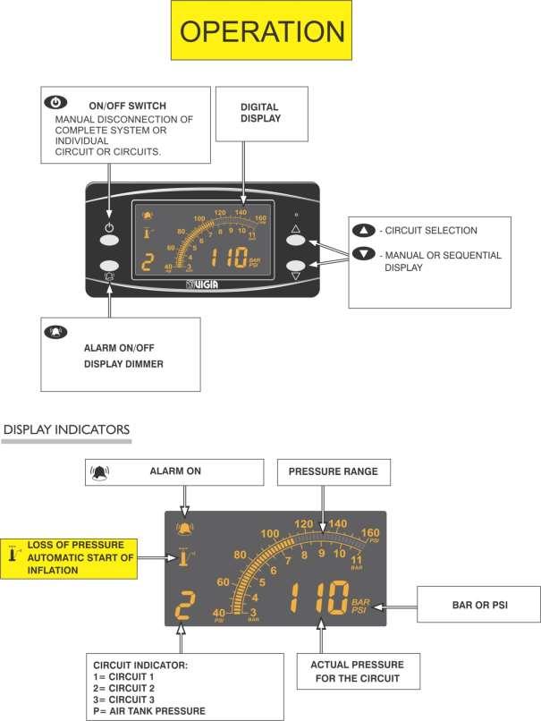
31 2.7 CONTROL AND DISPLAY MODULES VIGIA offers control modules for 2 or 3 independent pressures. Control Module NM343 is apt for exterior installation. The digital Display Module NM343 shows tire pressure for each circuit connected to it to a maximum of nine. Each circuit can be monitored sequentially or on demand. Display Module NM343 is for interior use only. LOCATION OF MODULES DISPLAY MODULE CONTROL MODULE CIRCUIT 3 CIRCUIT 2 CIRCUIT 1 AIR FILTER PROTECTION VALVE AIR TANK CONTROL MODULE NM343 The control module permanently controls and adjusts tire pressures in the tires and sends the information to the display module. Technical Characteristics Surge protection. Polarity inversion protection. Dimensions: length 194 mm. (7 5/8"); width 139 mm. (5 15/32"); height 61 mm. (2 13/32"). at 80 PSI (5.5 BAR). up to 9 different [pressures. Made of aluminum. Interior or exterior installation. 27
. 3- Air Intake from air tank. 4- Pressure 1 to tires. 5- Pressure 2 to tires. 6- Pressure 3 to tires.")

32 Location of Parts and components 1- Electrical connector (can bus) to the display module and to the electrical power socket. 2- Voltage indicator (12 or 24 V.). 3- Air Intake from air tank. 4- Pressure 1 to tires. 5- Pressure 2 to tires. 6- Pressure 3 to tires Installation Procedure Secure control module using all support, separators, rubber pads, bolts and nuts provided. Install to chassis frame or other vehicle part. Perforate the plate according to the holes available in the chassis or as needed Shortest side towards the module. 28


33 Important: Control module must be installed in the position indicated below to avoid water penetrations. DISPLAY MODULE NM343 The digital display shows tire pressure for each circuit connected to it to a maximum of nine. Each circuit can be monitored sequentially or on demand. Driver is alerted of low pressure conditions via audio and visual warnings. Technical Characteristics - Display module dimensions: 117 mm. x 58 mm. x 35 mm. - Up to 9 circuits can be connected to the display module. - Option to activate the alarm on 20 minute intervals. - Can Bus interface between control and display modules. - Sequential or manual visualization for each circuit. - Audio warning sound increases with magnitude of air loss in circuit. - System can be turned off completely or individual circuits can be stopped independently. - Digital interface for communication to remote location via telematic systems. - Iinterior installation only. 29

34 Operation 30
35 1 - System Activation The system turns on automatically when the vehicle s contact key is on. With contact key off and pressing for 4 seconds, the system will turn on the display and show tire pressures but the system will not be operational i.e. it will not inflate tires if needed. 2 - Display Tire pressures can be displayed in sequential or manual mode. Sequential Mode (default setting): Each circuit pressure is displayed for 10 second sequentially. 10 SECONDS 10 SECONDS 10 SECONDS Manual Mode: In Manual Mode circuit pressure and air tank pressure (P) can be displayed pressing or.. To turn Manual Mode on or off press the key or for 3. seconds. Important: The display goes into sequential mode automatically when loss of pressure is detected and it will show the circuit being inflated. 3 - Air Leaks The Vigia System, if activated, will automatically start inflation to a circuit with 3 or more PSI differential between actual and set tire pressure. Depending on the magnitude of the air loss, the system will warn the driver differently: a) 3 PSI drop takes more than 1.5 minutes to generate: System will automatically compensate the air loss but no alarm or warning will be produced. b) 3 PSI drop takes 1.5 minutes or less to generate: Automatic inflation, turns on intermittently and one beep every 9 seconds. 31
36 c) 3 PSI drop takes 30 seconds or less to generate: Automatic inflation, turns on intermittently and two beeps every 5 seconds. d) 3 PSI drop takes 2 seconds or less to generate: Automatic inflation, turns on permanently and three beeps every 2 seconds. Note: It there are air leaks in two or more circuits, only those circuit pressures will be displayed and in sequential order. In Manual Mode when an air leak is detected the system automatically turns to Sequential Mode and displays the circuit/s being pressurized. 4 Excessive Loss of Pressure If the air leak is too big and the vehicle s air compressor cannot compensate for it, the system will turn off automatically and will display the air tank pressure (P) warning the driver with 3 beeps every 2 seconds. Factory setting for the air tank pressure (P) warning is 80 PSI 5.5 BAR. 5 Alarm OFF Press to turn the alarm off. If turning the alarm off when the system is inflating one or more circuits, the alarm will automatically reconnect after 20 minutes. 6 Circuit Deactivation To temporarily deactivate a circuit proceed as follows: a) Turn display to Manual Mode pressing or for 3. seconds. b) Select the circuit to deactivate using or.. c) Press to confirm. A beep and the circuit number blinking is confirmation that the circuit has been deactivated. To cancel deactivation turn contact key off and on. 7 Dimming Display To decrease/increase display luminosity keep pressed the key until desired level. 32


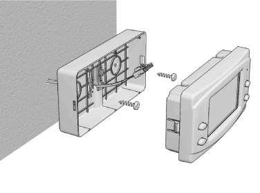

37 Installation Procedure A - Using support case with base B - Using tapping screws 33


38 C Using DIN format box To remove box remove first both lateral covers and press inwards the 4 locks. 34


39 3 PNEUMATIC AND ELECTRICAL CONNECTIONS TO SATELLITE MODULE Very Important: Match the guide in the connector plug to that in the module socket. Do not force this connection. IGNITIÓN KEY CONTACT POINT YELLOW GREEN WHITE-R GREEN-R YELLOW FREE YELLOW YELLOW-R GREEN WHITE-R GREEN ORIGINAL FUSE BOX 3 x FUSE 3A RED BLACK 4 x x 0.75 BLUE BLUE-R GREEN-R YELLOW YELLOW-R GREEN AIR FILTER CIRCUIT 1 TO TIRES CIRCUIT 2 TO TIRES CIRCUIT 3 TO TIRES PROTECTION VALVE AIR TANK 35


. 2.")


40 Important: The electrical installation is protected from dust and grease at both ends with shrink-wrap film. Do not remove this film until ready to actually connect the ends to the modules. If the film is damaged or removed, protect both terminals with electrical tape as shown in the figures. Connection to Satellite Module The Vigia electrical connection provides the wires that relay the digital information to the existing satellite module in the vehicle (please see diagram above.). Specific connection instructions should be requested to the telematics systems provider. 4 -TIRE PRESSURE CALIBRATION Before tire pressure calibration, make sure that: 1. Tires are cold (ambient temperature at least 4 hours after rolling). 2. Air tank pressure is at least 10 PSI higher than the maximum desired tire pressure. To assure this is the case, proceed as follows: a. Drain air tank completely. b. Connect the hose end from the air filter to a gauge. c. Start the engine and verify in the connected gauge that the compressor cut-off pressure is a minimum of 10 PSI higher than the maximum desired tire pressure. If that is not the case, increase the pressure using the compressor's governor. d. After this procedure, disconnect the gauge. 36

41 Tire Pressures can be set up to 160 PSI (11 BAR). CALIBRATION 1- Turn the ignition key to contact. 2- Insert the Calibration Tool into the control for calibration and press for four seconds until a continuous beep. Display is now in calibration mode. CALIBRATION TOOL. 3- Using or select PSI or BAR. Then press the calibration button. 4- Circuit 1 is shown. Using or set the desired pressure. Then press the calibration button.. 5- Circuit 2 is shown. Using or set the desired pressure. Then press the calibration button.. 6- Circuit 3 is shown. Using or set the desired pressure. Then press the calibration button.. 7- Air tank pressure is shown. Factory setting is 80 PSI (5.5 BAR) and this value should not be changed. Press the calibration button for 3 seconds until a beep is heard. Display is now in Sequential Mode. 37

42 5 - FINAL SYSTEM TESTING (in operation) 1- Verify that there are no air leaks in the system by turning off the system. If there are any leaks, the pressure readings will drop. To detect air leaks, use soapy water and monitor all connections and joints. Note: To facilitate detection of small air leaks, isolate the system network by sections through the use of plugs. 2 - Verify the operation of the safety mechanism by producing a very large air leak (For example, take a plug out, press the brakes repeatedly, etc.) - The Air Tank (P) pressure will be shown and the alarm will sound. 3- Confirm that air is reaching each tire. 4- Verify, after a few minutes, the correct pressure readings with respect to the set calibration. 5- Clean all the working surfaces. 6- Control the adjustment and aesthetics of all the elements: fastening nuts, hoses, body couplings, etc. 7- Verify that there are no air leaks in the air filter. 38
43 6 - RECOMMENDATIONS TO THE INSTALLER 1- Explain to the user how the system works. Provide the user with the following elements: User's Manual, N/F 3/8" plugs, straight joint 5/16", fastening nuts and hose provided with the system. 2- Inform the user that each time a tire is replaced it should have a pressure lower than the calibration pressure. The system only provides air to tires, it does not deflate tires. 3- Remind the user that rotor centring must be checked each time that a hub is dismounted to repair the brakes, to make bearing adjustments or replacements, etc. 4- Remind the user that the excess pressure generated by rolling must not be higher than 12% of the cold calibrated pressure. If the display indicate a pressure higher than that percentage, the user must verify whether the pressure is generated due to system failure or by rolling, proceeding as follows: - Disconnect one or more tires from the system. - Drive until display readings for connected tires exceed the specified tolerance. Compare pressures of connected and disconnected tires with a tire gauge. - If the pressures are similar, rolling causes the increase. If pressures differ, there may be damage to the control module. See "Failure location guide" in next section. 7 - FAILURE LOCATION GUIDE To quickly trace an air leak turn the system off and: a) If the display reading falls quickly, the leak is located in the system network between the VIGIA tire valve and the control module. b) If the display reading falls very slowly, the leak is located in the tire (puncture) or a VIGIA tire valve is defective or loosely attached to the tire stem. PROBLEM PROBABLE CAUSES SOLUTIONS Loss of pressure in display. With the system disconnected, the reading falls slowly. 1-Small pressure loss in one or more tires. Punctured tire. 2-Small loss between the original tire valve's thread and the VIGIA tire valve. 1 - Repair the affected tire. 2 -a) Adjust the VIGIA tire valves lightly with a wrench. b) Replace the VIGIA tire valve's joint. c) Check the original and VIGIA valves' thread (clean with a threading tool). Replace if necessary. 39
44 Los of pressure in display. With the system disconnected, the reading falls quickly. 1. Loss of pressure in the system network, between the tire valve and the control module inclusive, caused by: a) Worn out or defective rotor. b) Deteriorated hose. c) Couplings, connectors, joints, etc. d) Connection valves between the tractor and the trailer. 1. a) Replace the rotor. b) Replace the affected hose length. c) Tighten or replace the affected element. d) Replace the seal in the fixed joint valve. Display indicates more than 12% from the set calibration without alarm or warningsafter having rolled the unit. 1-Overheating caused by lower calibration than the one set by tire manufacturers. 2-Tire(s) with pressure higher than the one calibrated for the system. 3-Uneven load distribution. 4-Mechanical defects (mallets with worn or broken spring, misaligned axles, etc.). 5-Speeding. 6-Inadequate tires for the type of load. 7-Control module damage. 1-With cold tires reset the VIGIA system to the pressure indicated by tire manufacturers. 2-Deflate the tire(s) to a pressure lower than the calibrated one. The system will reset the tire(s) again. 3-Distribute the load correctly. 4-Repair the mechanical defects. 5-Slow down. 6-Replace tires with adequate specifications. 7-Replace control module. Display indicates higher than calibrated pressure, with alarm and warnings on. 1-Display calibration altered. 2-Display module damage. 1-Deflate the tire(s) to a pressure lower than the calibrated one and adjust the VIGIA Display Module again. 2-Replace Display module. 40
45 With on, the system is not inflating to the set pressure. 1-Insufficient pressure in the air tank (which must be 10 PSI higher than the maximum set pressure) caused by: a) Incorrect tank selection for air supply to the control module. 1- a) Correctly select air tank according to installation instructions for the air filter. b) Defective compressor operation. c) Compressor cut-off valve with low calibration. 2-Obstructed Air Filter. b) Repair compressor. c) Adjust the compressor cutoff valve. Repair if necessary. 2-Clean the air filter. 3-Strangled connecting hose between air tank and control module. 5-Control module damage. 3-Replace hose. 5-Replace control module. Pressure falls and system does not recover Indicator off. 1-Calibration altered. 2-Display module damage. 1-Calibratet the VIGIA Display Module again. 2-Replace display module. The air continues to leak from the tires while disconnecting a hose from the network. 1-Leak in tire valves. 1-a) Activate the valve's internal piston with a blunt element. b) Take the valve out and blow through the intake end, adding soapy water. Check for closing tightness, and replace if necessary. With the system disconnected, air leaks from the control module while disconnecting a hose from the network. 1-Control Module damage. 1-Replace control module. 41
46 When disconnecting trailer from truck, turns. on. 1-Leak in the fixed connection valve. 1-a) With the system in operation, activate the valve piston. b) Disconnect the system, disconnect the hose and blow on the other end, adding soapy water. c) Replace if necessary. Deflated tire and display indicating correct pressure. 1-Obstructed rotor, body couplings, hose, tire valve, connectors or joints. 2- Control Module damage 1-Replace affected element. 2--Replace control module. Display shows E --- (error code). Communication errors between control and display modules caused by: 1-Faulty connection at either end of the electrical cable. 2- Dirty connectors. 3- Connector with broken pins. 4- Electrical cable damaged. 5- Control or Display module damaged. 1- Verify and correct. 2- Clean using air gun. 3- Replace module. 4- Replace cable. 5- Replace Control or Display module. 42
47 INSTALLATION MAUNUAL VIGIA NM343 REVISION P.O.Box Avenue Road Toronto, Ontario M5M 0A1 CANADA Ruta 11 Km Guadalupe Norte Prov. de Santa Fe (S3574XAB) ARGENTINA ORDER ON-LINE /
ORDER ON-LINE /
 NM249 NM248 INTERNAL SYSTEMS FOR TRAILERS INSTALLATION MANUAL VERSION 1-2013 ORDER ON-LINE www.vigia.ca / 1-888 438-8444 IMPORTANT Installation requires an experienced mechanic with knowledge of tools
E C O L O G I C A L C O O L E R S ECON PARTS CATALOGUE
 E C O L O G I C A L C O O L E R S ECON PARTS CATALOGUE www.viesa.ca / 1-888 438-8444 IMPORTANT Installation requires an experienced mechanic with specific knowledge in the installation of the VIESA Ecological
E C O L O G I C A L C O O L E R S PARTS CATALOGUE. /
 E C O L O G I C A L C O O L E R S AGRO PARTS CATALOGUE www.viesa.ca / 1-888 438-8444 IMPORTANT Installation requires an experienced mechanic with specific knowledge in the installation of the VIESA Ecological
E C O L O G I C A L C O O L E R S HOLIDAY II PARTS CATALOGUE
 E C O L O G I C A L C O O L E R S HOLIDAY II PARTS CATALOGUE www.viesa.ca / 1-888 438-8444 IMPORTANT Installation requires an experienced mechanic with specific knowledge in the installation of the VIESA
E C O L O G I C A L C O O L E R S INTELLIGENT 12 PARTS CATALOGUE
 E C O L O G I C A L C O O L E R S INTELLIGENT 12 PARTS CATALOGUE www.viesa.ca / 1-888 438-8444 IMPORTANT Installation requires an experienced mechanic with specific knowledge in the installation of the
IVTM Installation Manual
 Integrated Vehicle Tire Pressure Monitoring IVTM Installation Manual 2nd edition Copyright WABCO 2006 Vehicle Control Systems An American Standard Company The right of amendment is reserved Version 002/06.06(us)
Key Features: Alerts when tire pressure is too low Alerts when tire pressure is too high Alerts when tire temperature is too high
 Key Features: Visual and audible warnings Set desired PSI level Alerts when tire pressure is too low Alerts when tire pressure is too high Alerts when tire temperature is too high Mounts to windshield
Key Features: Visual and audible warnings Set desired PSI levels Adjustable windshield mount included
 Key Features: Visual and audible warnings Set desired PSI levels Adjustable windshield mount included Alerts when tire pressure is too low or too high Alerts when tire temperature is too high Easy Plug-In
USER MANUAL. Keep this User Manual in the vehicle on which Halos are installed.
 Keep this User Manual in the vehicle on which Halos are installed. USER MANUAL 3 IMPORTANT SAFETY INFORMATION The Halo is not intended to replace regular pressure-checks and tire maintenance practices
FAX
 INSTALLATION INSTRUCTIONS 6090 Air Suspension Kit (pat. pending) 1999-2006 Tahoe, Suburban, Avalanche, Yukon Thank you for purchasing a quality Hellwig Product. PLEASE READ THIS INSTRUCTION SHEET COMPLETELY
Section 10 Chapter 17
 Section 10 Chapter 17 24 Valve, 8.3 Liter Engine Air Intake System Note: All coding used in the 8.3 Liter and 9 Liter engine manuals are Cummins engine codes. These engine codes have no meaning to New
TurfDefender Electronic Leak Detector Kit Reelmaster 5000, 6000 and 5010 Series Traction Units
 Form No. 56 586 Rev A TurfDefender Electronic Leak Detector Kit Reelmaster 5000, 6000 and 500 Series Traction Units Model No. 05 Installation Instructions The Installation Instructions for Reelmaster 5000/6000
Free Float Air Trap G8
 172-65193MA-06 (G8) 24 June 2015 ISO 9001/ ISO 14001 Manufacturer Kakogawa, Japan is approved by LRQA LTD. to ISO 9001/14001 Free Float Air Trap G8 Copyright 2015 by TLV CO., LTD. All rights reserved 1
PowerLevel s e r i e s
 Owner s Manual Hydraulic Leveling CONTENTS Introduction Operation Control Panel Automatic Leveling Manual Leveling Retracting Jacks Remote Operation Care & Maintenance Troubleshooting Error Codes 1 2 2
WARNING: Only perform this installation if you are experienced, fully equipped mechanic.
 DYNATRAC V3.2 2005-Present Ford Super Duty 250/350-4x4, Front Axle, Free Spin Conversion Kit Some of the less common tools, which will be required: 6 point Spanner socket (OTC #7090-A or equivalent). These
FAX
 INSTALLATION INSTRUCTIONS 6299 Air Suspension Kit (pat. pending) 2009+ Dodge 1500 Pickup with Rear Coil Springs Thank you for purchasing a quality Hellwig Product. PLEASE READ THIS INSTRUCTION SHEET COMPLETELY
PRODUCT SAFETY NOTICE DEALER/INSTALLER NOTICE
 PRODUCT SAFETY NOTICE Congratulations. This vehicle has been equipped with a Firestone air suspension system. This suspension will enhance the vehicle s handling when loaded, however, the vehicle s performance
OWNERS MANUAL. GMC C K AND 19K GVW CHASSIS CAB 2004-NEWER MODELS (Link Part No. 8M000050) PROUDLY INSTALLED BY : COMPANY : INSTALLER SIGNATURE :
 PROUDLY INSTALLED BY : COMPANY : INSTALLER SIGNATURE :") OWNERS MANUAL GMC C5500 15K AND 19K GVW CHASSIS CAB 2004-NEWER MODELS (Link Part No. 8M000050) Link Mfg. Ltd. 223 15th St. N.E. Sioux Center, IA USA 51250-2120 (712) 722-4868 Fax (712) 722-4779 QUESTIONS?
OWNERS MANUAL GMC C5500 15K AND 19K GVW CHASSIS CAB 2004-NEWER MODELS (Link Part No. 8M000050) Link Mfg. Ltd. 223 15th St. N.E. Sioux Center, IA USA 51250-2120 (712) 722-4868 Fax (712) 722-4779 QUESTIONS?
INSTALLATION INSTRUCTIONS
 INSTALLATION INSTRUCTIONS GMT 560 (4500/5500) CREW CAB (2351A000) Link Mfg. Ltd. 223 15th St. N.E. Sioux Center, IA USA 51250-2120 The CABMATE MODEL 2351A000 fits the 2003 and later GM 4500 / 5500 crew
PNEUMATIC SLIDING VALVE
 INSTALLATION, OPERATION, & #: MM-SV001 6-23-09 Rev. A Page 1 of 8 PNEUMATIC SLIDING VALVE PART NUMBERS (Including, but not inclusive) SV704MSTS, SV714MSTS, SV754MSTS, SV764MSTS, SV774MSTS, SV706MSTS, SV716MSTS,
BRAKE SYSTEM Return To Main Table of Contents
 BRAKE SYSTEM Return To Main Table of Contents GENERAL... 2 BRAKE PEDAL... 10 MASTER CYLINDER... 13 BRAKE BOOSTER... 16 BRAKE LINE... 18 PROPORTIONING VALVE... 19 FRONT DISC BRAKE... 20 REAR DRUM BRAKE...
SECTION ZF FRONT AXLE
 04-101.01/ 1 2011JA14 SECTION 04-101.01 6 3 5 1 2 9 1. Upper radius rod 2. Lower radius rod 3. Caliper 4. BRAKE Disk 5. Pneumatic connector 6. Hub 7. steering knuckle 8. Grease Fitting 9. Pneumatic connector
Kit INSTALLATION GUIDE. 5 psi Low Pressure Sensor (Single Gauge)
") ª Kit 25592 5 psi Low Pressure Sensor (Single Gauge) MN-333 (131107) ECR 7119 INSTALLATION GUIDE For maximum effectiveness and safety, please read these instructions completely before proceeding with installation.
ª Kit 25592 5 psi Low Pressure Sensor (Single Gauge) MN-333 (131107) ECR 7119 INSTALLATION GUIDE For maximum effectiveness and safety, please read these instructions completely before proceeding with installation.
HUB & WHEEL INSTALLATION
 HUB & WHEEL INSTALLATION 1.0 SCOPE This specification covers the torque requirements for the attachment of all component parts of Spoke Wheels, Rims, Tyres and Hub assemblies. 1.1 Spoke Wheels CAUTION:
PRODUCT SAFETY NOTICE
 PRODUCT SAFETY NOTICE Congratulations. This vehicle has been equipped with a Firestone air suspension system. This suspension will enhance the vehicle s handling when loaded, however, the vehicle s performance
Sachs shock manual. ( ) 2 & 4 Stroke RR Enduro. ( ) RS Dual Sport
 2 & 4 Stroke RR Enduro. ( ) RS Dual Sport") Sachs shock manual (2013 2015) 2 & 4 Stroke RR Enduro (2014-2015) RS Dual Sport 1 Introduction The procedures in this manual must take place in a clean environment using professional tools and some specific,
Sachs shock manual (2013 2015) 2 & 4 Stroke RR Enduro (2014-2015) RS Dual Sport 1 Introduction The procedures in this manual must take place in a clean environment using professional tools and some specific,
Air Trap TATSU2. Copyright 2013 by TLV CO., LTD. All rights reserved ISO 9001/ ISO M-02 (TATSU2) 7 August 2013.
 7 August 2013.") 172-65177M-02 (TATSU2) 7 August 2013 ISO 9001/ ISO 14001 Manufacturer Kakogawa, Japan is approved by LRQA LTD. to ISO 9001/14001 Air Trap TATSU2 Copyright 2013 by TLV CO., LTD. All rights reserved 1 Contents
172-65177M-02 (TATSU2) 7 August 2013 ISO 9001/ ISO 14001 Manufacturer Kakogawa, Japan is approved by LRQA LTD. to ISO 9001/14001 Air Trap TATSU2 Copyright 2013 by TLV CO., LTD. All rights reserved 1 Contents
Valve stems pictured may differ from stems packed in kit.
 1504-1510 Key Features: Visual and audible warnings Set desired PSI level Mounts to windshield or dashboard Alerts when tire pressure is too low Alerts when tire pressure is too high Alerts when tire temperature
Kit psi Low Pressure Sensor (Dual Gauge)
") ª Kit 25812 5 psi Low Pressure Sensor (Dual Gauge) MN-337 (111107) ECR 7119 INSTALLATION GUIDE For maximum effectiveness and safety, please read these instructions completely before proceeding with installation.
ª Kit 25812 5 psi Low Pressure Sensor (Dual Gauge) MN-337 (111107) ECR 7119 INSTALLATION GUIDE For maximum effectiveness and safety, please read these instructions completely before proceeding with installation.
Installation Notes: #86000-R Race Series +3.5 L/T Kit
 159 North Maple St. Unit J, CORONA CA 92880 P. 951-737-9682 F. 951-737-9006 WWW.CHAOSFAB.COM Installation Notes: #86000-R Race Series +3.5 L/T Kit Factory manual is recommended for removal and re-installation
INSTALLATION INSTRUCTIONS
 INSTALLATION INSTRUCTIONS REAR DISC BRAKE CONVERSION KIT A126-1 1973-87 CHEVROLET 1/2 TON 2WD Thank you for choosing STAINLESS STEEL BRAKES CORPORATION for your braking needs. Pleases take the time to
Cybex Arc Trainer Owner s & Service Manual. 7 - Service
 7 - Service Table of Contents......... iii Warnings/Cautions All warnings and cautions listed in this chapter are as follows:! WARNING: All maintenance activities shall be performed by qualified personnel.
 AUTOGARD SERIES 820 TORQUE LIMITER Installation and Maintenance Manual DB0009 Issue 11 21 Feb 2017 British Autogard Ltd 2 Wilkinson Rd., Love Lane Industrial Estate, Cirencester, Glos., GL7 1YT UK Tel.
SRS AIRBAG Toyota RAV4. Supplemental Restraint System - RAV4 PRECAUTION CAUTION:
 2005 RESTRAINTS Supplemental Restraint System - RAV4 SRS AIRBAG PRECAUTION CAUTION: The TOYOTA RAV4 is equipped with SRS that includes a driver airbag, front passenger airbag, side airbag and curtain shield
INSTALLATION INSTRUCTIONS Auto Level Compressor Kit IMPORTANT NOTES
 INSTALLATION INSTRUCTIONS 4880 Auto Level Compressor Kit Thank you for purchasing a quality Hellwig Product. PLEASE READ THIS INSTRUCTION SHEET COMPLETELY BEFORE STARTING YOUR INSTALLATION IMPORTANT NOTES
SYSTEM SAVER 318 AIR COMPRESSOR FOR MACK E-TECH AND ASET ENGINES MAINTENANCE MANUAL
 SYSTEM SAVER 318 AIR COMPRESSOR FOR MACK E-TECH AND ASET ENGINES MAINTENANCE MANUAL NON-THROUGH DRIVE THROUGH DRIVE Service Notes About This Manual This manual provides service and repair procedures for
# and # FAST Fuel System Kits
 1 INSTRUCTIONS #307500 and #307501 Fuel System Kits Thank you for choosing products; we are proud to be your manufacturer of choice. Please read this instruction sheet carefully before beginning the installation.
Air Lift. Kits PERFORMANCE / /78637 BMW E36, E46 Chassis Rear Application (With and Without Shocks) INSTALLATION GUIDE
 INSTALLATION GUIDE") Air Lift PERFORMANCE Kits 75636/78636 75646/78637 BMW E36, E46 Chassis Rear Application (With and Without Shocks) INSTALLATION GUIDE PERFORMANCE SUSPENSION PARTS For maximum effectiveness and safety, please
Air Lift PERFORMANCE Kits 75636/78636 75646/78637 BMW E36, E46 Chassis Rear Application (With and Without Shocks) INSTALLATION GUIDE PERFORMANCE SUSPENSION PARTS For maximum effectiveness and safety, please
OPERATING INSTRUCTIONS AND TROUBLE SHOOTING GUIDE
 OPERATING INSTRUCTIONS AND TROUBLE SHOOTING GUIDE Thank you for purchasing Driverite-Firestone Air Suspension System. You have purchased a quality product from the world s number one Air Spring Manufacturer.
INSTALLATION INSTRUCTIONS
 2806 INSTALLATION INSTRUCTIONS SECTION - AIR SPRING SECTION 2 - AIR ACCESSORY -6 ! IMPORTANT PLEASE DON T HURT YOURSELF, YOUR KIT OR YOUR VEHICLE. TAKE A MINUTE TO READ THIS IMPORTANT INFORMATION. This
Installation Instructions
 Installation Instructions for 15912 to 15916 Electric Fuel Pumps & Fuel Pressure Regulators Installation Instructions WARNING! These instructions must be read and fully understood before beginning the
SECTION 35iS/U: LANDING GEAR & ENGINE MOUNT
 WD-1221 ENGINE MOUNT STANDOFF SECTION 35iS/U: LANDING GEAR & ENGINE MOUNT U-01203E-1 INBOARD DOUBLER PLATE U-01203B-1 INBOARD WEAR PLATE U-01203C-1 BEARING PLATE U-01203-2 (U-01203-1 SHOWN) INBOARD MAIN
INSTALLATION INSTRUCTIONS Air Spring Kit Dodge WD IMPORTANT NOTES
 INSTALLATION INSTRUCTIONS 6211 Air Spring Kit 2003+ Dodge 1500 4WD Thank you for purchasing a quality Hellwig Product. PLEASE READ THIS INSTRUCTION SHEET COMPLETELY BEFORE STARTING YOUR INSTALLATION IMPORTANT
2.- HANDLING OF VALVES BEFORE ASSEMBLY 3.- FITTING THE VALVE TO THE REST OF THE ASSEMBLY 5.- PERIODICAL INSPECTION OF THE VALVE AND MAINTENANCE
 Page 1 of 16 CONTENTS 1.- INTRODUCTION 2.- HANDLING OF VALVES BEFORE ASSEMBLY 3.- FITTING THE VALVE TO THE REST OF THE ASSEMBLY 4.- OPERATION OF A BALL VALVE 5.- PERIODICAL INSPECTION OF THE VALVE AND
ONBOARD AIR SYSTEM FOR ALL VEHICLES APPLICATIONS
 ONBOARD SYSTEM FOR ALL VEHICLES APPLICATIONS Thank you and congratulations on the purchase of a Pacbrake onboard air system. Please read the manual prior to starting to ensure you can complete the installation
Meritor WABCO Antilock Braking System (ABS) 42.06
 42.06") Meritor WABCO Antilock Braking System (ABS) 4.06 Control Valve Replacement Replacement NOTE: Wire repairs may require the use of special tools for certain connectors and terminals. See Group 54 for information
Meritor WABCO Antilock Braking System (ABS) 4.06 Control Valve Replacement Replacement NOTE: Wire repairs may require the use of special tools for certain connectors and terminals. See Group 54 for information
INSTALLATION INSTRUCTIONS
 INSTALLATION INSTRUCTIONS PERFORMANCE AT THE WHEELS KIT W125-42 GM 10 & 12 Bolt Rear Axles with Staggered or non-staggered Shocks with C-Clips Thank you for choosing STAINLESS STEEL BRAKES CORPORATION
2006 MINI Cooper SUSPENSION Wheels & Tires - Repair Instructions - Cooper (1.6L) R50/W10 & Cooper S
 R50/W10 & Cooper S") WHEELS 2002-05 SUSPENSION Wheels & Tires - Repair Instructions - Cooper (1.6L) R50/W10 & Cooper S 36 10 300 REMOVING OR INSTALLING FRONT OR REAR WHEEL NOTE: For Special Tool identification, see WHEEL AND
WHEELS 2002-05 SUSPENSION Wheels & Tires - Repair Instructions - Cooper (1.6L) R50/W10 & Cooper S 36 10 300 REMOVING OR INSTALLING FRONT OR REAR WHEEL NOTE: For Special Tool identification, see WHEEL AND
R4TECH PRODUCT SAFETY NOTICE
 R4TECH PRODUCT SAFETY NOTICE Congratulations. This vehicle has been equipped with an R4Tech suspension system that provides the ride quality of a full-air suspension with the ease of installation of a
INSTALLATION INSTRUCTIONS
 28 INSTALLATION INSTRUCTIONS SECTION - AIR SPRING SECTION 2 - AIR ACCESSORY 2-5 ! IMPORTANT PLEASE DON T HURT YOURSELF, YOUR KIT OR YOUR VEHICLE. TAKE A MINUTE TO READ THIS IMPORTANT INFORMATION. This
DEFENDER SERIES. 5 Gallon, Double Walled, Field Replaceable Spill Container Model Series INSTALLATION, OPERATION, & MAINTENANCE
 DEFENDER SERIES 5 Gallon, Double Walled, Field Replaceable Spill Container Model 705-550 Series INSTALLATION, OPERATION, & MAINTENANCE Franklin Fueling Systems 3760 Marsh Rd. Madison, WI 53718 USA Tel:
Coil Spring Conversion Kit
 Coil Spring Conversion Kit Land Rover Discovery 3 INTRODUCTION Thank you for your purchase of a coil spring conversion kit from Dunlop Systems and Components Limited, suitable for the Land Rover Discovery
Hydraulic Immediate Need Power Pack
 Safety, Operation, and Maintenance Manual WARNING Improper use of this tool can result in serious bodily injury This manual contains important information about product function and safety. Please read
MODEL NUMBER: MEDIUM DUTY ONBOARD AIR SYSTEM
 MODEL NUMBER: 10003 MEDIUM DUTY ONBOARD AIR SYSTEM IMPORTANT: It is essential that you and any other operator of this product read and understand the contents of this manual before installing and using
INSTALLATION INSTRUCTION 88094
 INSTALLATION INSTRUCTION 88094 FOR RANCHO SUSPENSION SYSTEM RS6594B 4WD & 2WD NISSAN TITAN READ ALL INSTRUCTIONS THOROUGHLY FROM START TO FINISH BEFORE BEGINNING INSTALLATION Rev D IMPORTANT NOTES! WARNING:
INSTALLATION INSTRUCTIONS
 INSTALLATION INSTRUCTIONS PERFORMANCE AT THE WHEELS KITS W156-6 & W156-7 1965-74 MOPAR B & E BODY Thank you for choosing STAINLESS STEEL BRAKES CORPORATION for your braking needs. Pleases take the time
Part # Mopar LX Level 1 Air Suspension System
 Part # 13040199 05-14 Mopar LX Level 1 Air Suspension System Front Components: 1 1304409 Front RQ ShockWave Kit for Stock Lower Arms Rear Components: 1 13044099 Rear CoolRide Kit 1 13040709 RQ Series Rear
INSTALLATION INSTRUCTIONS
 INSTALLATION INSTRUCTIONS REAR DISC CONVERSION KIT A126-2 1988-98 C1500 2WD 10" REAR DRUM Thank you for choosing STAINLESS STEEL BRAKES CORPORATION for your braking needs. Pleases take the time to read
69-74 VW Beetle IRS Rear Kit Part No
 www.airliftcompany.com 69-74 VW Beetle IRS Rear Kit Part No. 75615 MN-476 (01102) ECN 3455 Please read these instructions completely before proceeding with installation A C B E D AA F F ITEM QTY. PART
RideStar RHP Series Sliding Tandem Trailer Air Suspension System
 Maintenance Manual 14S RideStar RHP Series Sliding Tandem Trailer Air Suspension System Revised 05-14 Service Notes About This Manual This manual provides the correct lubrication, service and installation
OWNERS MANUAL GM C4500/C5500 DANA MODEL S135 REAR AXLE 2003-NEWER MODELS LINK MFG. PART NO. 8M PROUDLY INSTALLED BY : COMPANY :
 OWNERS MANUAL GM C4500/C5500 DANA MODEL S135 REAR AXLE 2003-NEWER MODELS LINK MFG. PART NO. 8M000030 Link Mfg. Ltd. 223 15th St. N.E. Sioux Center, IA USA 51250-2120 (712) 722-4874 Fax (712) 722-4876 QUESTIONS?
INSTALLATION INSTRUCTIONS
 2807 INSTALLATION INSTRUCTIONS SECTION - AIR SPRING SECTION 2 - AIR ACCESSORY -6 ! IMPORTANT PLEASE DON T HURT YOURSELF, YOUR KIT OR YOUR VEHICLE. TAKE A MINUTE TO READ THIS IMPORTANT INFORMATION. This
FRONT SUSPENSION GROUP CONTENTS GENERAL INFORMATION SPECIFICATIONS STRUT ASSEMBLY FRONT SUSPENSION DIAGNOSIS.
 33-1 GROUP 33 FRONT SUSPENSION CONTENTS GENERAL INFORMATION 33-2 SPECIFICATIONS 33-3 FASTENER TIGHTENING SPECIFICATIONS 33-3 GENERAL SPECIFICATIONS 33-3 SERVICE SPECIFICATIONS 33-3 LUBRICANT 33-3 DIAGNOSIS
Webinar Series APTA Standards Quarterly Webinar Series
 1 Webinar Series APTA Standards Quarterly Webinar Series Presented by APTA Brake and Chassis Working Group Disc Brake Wheels On Inspection January 26, 2017 2 Moderator Presenter Jerry Guaracino Assistant
HEAVY DUTY ONBOARD AIR SYSTEM PART NO
 IMPORTANT: It is essential that you and any other operator of this product read and understand the contents of this manual before installing and using this product. SAVE THIS MANUAL FOR FUTURE REFERENCE
<THESE INSTRUCTIONS MUST BE GIVEN TO THE END USER> B&W
 B&W Trailer Hitches 6 Hawaii Rd / PO Box 86 Humboldt, KS 66748 P:60.473664 F:60.869.903 Turnoverball Gooseneck Hitch Installation Instructions MODEL 08
Fitting Instructions: Street Triple from VIN and Street Triple R from VIN A
 English Fitting Instructions: Street Triple from VIN 560477 and Street Triple R from VIN 560477 A9808113 Thank you for choosing this Triumph genuine accessory kit. This accessory kit is the product of
INSTALLATION INSTRUCTIONS PARTS LIST INSTALLATION INSTRUCTIONS AIR CONTROL KIT (800A0168 OR 800A0169)
") INSTALLATION INSTRUCTIONS INSTALLATION INSTRUCTIONS PARTS LIST AIR CONTROL KIT (800A0168 OR 800A0169) Link mfg. Ltd. 223 15th St. N.E. Sioux Center, IA USA 51250-2120 (712) 722-4874 Fax (712) 722-4876
INSTALLATION INSTRUCTIONS INSTALLATION INSTRUCTIONS PARTS LIST AIR CONTROL KIT (800A0168 OR 800A0169) Link mfg. Ltd. 223 15th St. N.E. Sioux Center, IA USA 51250-2120 (712) 722-4874 Fax (712) 722-4876
Purging Air From Divider Block Lubrication Systems
 FROST ENGINEERING SERVICE Purging Air From Lubrication Systems A D I V I S I O N O F G E C S E Y S A L E S & S E R V I C E DESCRIPTION Divider block lubrication systems operate correctly only when all
3M Overhaul Service Kit
 SERVICE INSTRUCTIONS FOR 3M 12,000 RPM 3 in. (77 mm) RANDOM ORBITAL SANDERS 3M Overhaul Service Kit The part number 20346, 3M Overhaul Service Kit, contains all the replacement parts that naturally wear
Parking brake Mechanical brake acting on rear wheels
 11 Brake System 11.1 General SPECIFICATIONS EJTC0010 Master cylinder Type Tandem type I.D. mm(in.) 20.64 mm (0.813 in.) Fluid level warning sensor Provided Brake booster Type Vacuum Boosting ratio 4.0
C50254A PH3 AIR INTAKE SHUT-OFF VALVE DODGE 6.7L CUMMINS WITH POWERGUARD SMART OVERSPEED LIMITER
 AIR INTAKE EMERGENCY SHUT-OFF VALVE C50254A PH3 AIR INTAKE SHUT-OFF VALVE WITH POWERGUARD SMART OVERSPEED LIMITER 2013-2017 DODGE 6.7L CUMMINS www.powerhalt.com INSTALLATION REQUIREMENTS & RECOMMENDATIONS:
Keystone Series GR resilient seated butterfly valves GRW/GRL Installation and operation manual
 Before installation these instructions must be fully read and understood Important Before valves are installed or used the following actions are recommended. 1. Valves/parts have to be inspected and thoroughly
SUSPENSION 2-1 SUSPENSION TABLE OF CONTENTS
 XJ SUSPENSION 2-1 SUSPENSION TABLE OF CONTENTS page ALIGNMENT... 1 FRONT SUSPENSION... 7 page REAR SUSPENSION... 16 ALIGNMENT TABLE OF CONTENTS page AND WHEEL ALIGNMENT...1 DIAGNOSIS AND TESTING SUSPENSION
INSTALL MANUAL. FOR ON LINE ORDERING- E Commerce Visit Our Website
 INSTALL MANUAL FOR ON LINE ORDERING- E Commerce Visit Our Website WWW.PRESSUREGUARD.COM Contact Information Technical Support: Chris@pressureguard.com Sales Support: Sales@pressureguard.com By Phone: 615-227-6024
Department of Motor Vehicles Loudoun County Public Schools School Bus Inspection Study Guide Hand Out
 Department of Motor Vehicles Loudoun County Public Schools School Bus Inspection Study Guide Hand Out During the actual tests, you will be expected to point or touch each of the parts of your vehicle.
Page 1 of 17. Part# M0200 Rev.11 7/29/2016
 Part# M0200 Rev.11 7/29/2016 This manual contains important information concerning the installation and operation of the product listed above. Read manual thoroughly and keep for future reference INSTRUCTIONS
TOYOTA TUNDRA BIG BRAKE KIT Section I - Installation Preparation
 TOYOTA TUNDRA 2007- BIG BRAKE KIT Section I - Installation Preparation Part Number: PTR09-34070 Kit Contents Item # Quantity Reqd. Description 1 1 Brake Rotor, LH Front 2 1 Brake Rotor, RH Front 3 1 Brake
INSTALLATION INSTRUCTIONS
 280 INSTALLATION INSTRUCTIONS SECTION - AIR SPRING SECTION 2 - AIR ACCESSORY 2-5 ! IMPORTANT PLEASE DON T HURT YOURSELF, YOUR KIT OR YOUR VEHICLE. TAKE A MINUTE TO READ THIS IMPORTANT INFORMATION. This
CompoSeal butterfly valves, wafer style Installation & Maintenance Instructions
 Please read these instructions carefully This symbol indicates important messages and safety instructions. Intended valve use The valve is intended to be used only in applications within the pressure/temperature
INSTALLATION INSTRUCTIONS
 INSTALLATION INSTRUCTIONS PERFORMANCE AT THE WHEELS KIT W155-5 CHRYSLER 8 3 /4" & 9 3 /4" REAR AXLES Thank you for choosing STAINLESS STEEL BRAKES CORPORATION for your braking needs. Please take the time
ELECTRIC FUEL PUMPS P/N , , & FUEL PRESSURE REGULATOR P/N
 ELECTRIC FUEL PUMPS P/N 80000100, 80000101, & 80000102 FUEL PRESSURE REGULATOR P/N 80000103 Installation Instructions 199R10583 These instructions must be read and fully understood before beginning the
HALLMARK INDUSTRIES INC
 Performance Part No. HP. CONVERTIBLE JET PUMP USER S MANUAL GPH of Water @ Total Discharge Pressure of 40 psi Max. Pressure Max suction (shallow well) Max Suction (deep well) Max GPM (@0 head) Max Discharge
Maintenance Manual 3-INCH INTERNAL VALVE F660 SERIES
 Maintenance Manual 3-INCH INTERNAL VALVE F660 SERIES REVISION 1.1 03/15/2002 LIST OF EFFECTIVE PAGES On a revised page, the portion of text or illustrations affected by the change is indicated by a vertical
Part # Galaxie Level 1 Complete Air Suspension System
 350 S. St. Charles St. Jasper, In. 47546 Ph. 812.482.2932 Fax 812.634.6632 www.ridetech.com Part # 12160199 60-64 Galaxie Level 1 Complete Air Suspension System Front Components: 1 12162409 Front RQ Series
'99-03 CHEVROLET/GMC IFS 4WD 6" SUSPENSION SYSTEM P/N INSTALLATION INSTRUCTIONS
 1/16/04 '99-03 CHEVROLET/GMC IFS 4WD 6" SUSPENSION SYSTEM P/N. 10-41099 INSTALLATION INSTRUCTIONS NOTE: Each Lift Kit and options to Lift Kits are packaged separately. Therefore, installation procedures
Temperature Sensor Series
 GENERAL DESCRIPTION The patented* No. 85026-Series Temperature Sensor contains a two-position valve operated by temperature variations around the integral sensing bulb. It is used to vent or block a pneumatic
INSTALLATION & OWNER S MANUAL
 Rev. R p. 1 of 16 INSTALLATION & OWNER S MANUAL V4211 HARD SIDED CAB KIT and/or V4275 CAMO HARD SIDED CAB KIT INSTALLATION & OWNER S MANUAL The contents of this envelope are the property of the owner.
GENUINE PARTS INSTALLATION INSTRUCTIONS
 GENUINE PARTS INSTALLATION INSTRUCTIONS 1. DESCRIPTION: 2. APPLICATION: 3. PART NUMBER(S) REQUIRED FOR INSTALLATION: 4. KIT CONTENTS: Item Qty. Fog Lamp Kit Titan MY16 999F1 W4000 Fog Lamp Kit Part Description
HPC Radiator Fan Control Kit
 Revised 06.25.14 www.hpcontrols.ca odels Covered 102002, 102003, 102004, 102005 HPC Radiator Fan Control Kit (102002 Shown) The HPC Radiator Fan Controllers provide automatic control over one or more electric
3M Overhaul Service Kit
 SERVICE INSTRUCTIONS FOR 3M 12,000 RPM 5 in. (127 mm) and 6 in. (150 mm) RANDOM ORBITAL SANDERS 3M Overhaul Service Kit The part number 20347, 3M Overhaul Service Kit, contains all the replacement parts
Not required for most applications. Not required for most applications. High pressure ( provided) High pressure ( provided)
 High pressure ( provided)") ELECTRIC FUEL PUMPS P/N 12-801-1, 712-801-1, 12-802-1, 12-802-2, 712-802-1, 12-812, 12-815-1, & 712-815-1 FUEL PRESSURE REGULATORS P/N 12-500, 12-501, 12-803, 12-803BP, 12-804, & 15812NOS Installation
ELECTRIC FUEL PUMPS P/N 12-801-1, 712-801-1, 12-802-1, 12-802-2, 712-802-1, 12-812, 12-815-1, & 712-815-1 FUEL PRESSURE REGULATORS P/N 12-500, 12-501, 12-803, 12-803BP, 12-804, & 15812NOS Installation
92-00 Civic/ Integra/ Del Sol/ Accord/ CRX
 92-00 Civic/ 94-01 Integra/ 93-97 Del Sol/ 90-97 Accord/ 92-95 CRX Front Kit Part No. 75440 www.airliftperformance.com Please read these instructions completely before proceeding with installation MN-513
INSTALLATION INSTRUCTIONS
 INSTALLATION INSTRUCTIONS DISC BRAKE CONVERSION KITS A120-4 & A120-5 1964-1/2-66 Ford & Mercury Thank you for choosing STAINLESS STEEL BRAKES CORPORATION for your braking needs. Pleases take the time to
INSTALLATION INSTRUCTIONS
 INSTALLATION INSTRUCTIONS R1 REAR DRUM TO DISC BRAKE CONVERSION KIT A130-3 JEEP CJ SERIES W/AMC-20 REAR AXLES AND 5 x 5-1/2" BOLT CIRCLE Thank you for choosing STAINLESS STEEL BRAKES CORPORATION for your
DYNA OIL COOLER AND THERMOSTAT KIT
 INSTRUCTIONS -J000 REV. 07-5-00 Kit Numbers 6985-0 (Chrome) and 6989-0 (Silver) General DYNA OIL COOLER AND THERMOSTAT KIT These oil cooler kits feature a thermostat built-in to the oil filter mount. These
BRAKE E
 8-1 GENERAL...8-2 SPECIFICATIONS...8-6 COMPONENTS...8-7 FRONT BRAKE...8-12 DISASSEMBLY INSPECTION REASSEMBLY (Pn1, Cu2 3 TON SERIES)...8-12 DISASSEMBLY INSPECTION REASSEMBLY (Pn2 3 TON SERIES)...8-17 BRAKE
BOLT-ON AND WELD-ON FLUSH FLOOR SLIDEOUT SYSTEMS OPERATION AND SERVICE MANUAL
 BOLT-ON AND WELD-ON FLUSH FLOOR SLIDEOUT SYSTEMS OPERATION AND SERVICE MANUAL TABLE OF CONTENTS SYSTEM...... Warning........ Description...... Prior to Operation OPERATION... Main Components... Mechanical...
Safety, Operation and Maintenance Instructions For Long & Short Nose Upholstery Air Stapler (NS10 & NS11)
") Safety, Operation and Maintenance Instructions For Long & Short Nose Upholstery Air Stapler (NS10 & NS11) Important: Drop 3 drops of oil into the stapler air inlet BEFORE first use. See page 2. Please
Safety, Operation and Maintenance Instructions For Long & Short Nose Upholstery Air Stapler (NS10 & NS11) Important: Drop 3 drops of oil into the stapler air inlet BEFORE first use. See page 2. Please
SUSPENSION 2-1 SUSPENSION TABLE OF CONTENTS
 DN SUSPENSION 2-1 SUSPENSION TABLE OF CONTENTS page ALIGNMENT... 1 FRONT SUSPENSION - 4x2... 6 page FRONT SUSPENSION - 4x4... 14 REAR SUSPENSION... 23 ALIGNMENT TABLE OF CONTENTS page AND OPERATION WHEEL