BRAKE E
|
|
|
- Maria Short
- 5 years ago
- Views:
Transcription
1 8-1 GENERAL SPECIFICATIONS COMPONENTS FRONT BRAKE DISASSEMBLY INSPECTION REASSEMBLY (Pn1, Cu2 3 TON SERIES) DISASSEMBLY INSPECTION REASSEMBLY (Pn2 3 TON SERIES) BRAKE AIR BLEEDING BRAKING FORCE INSPECTION ADJUSTMENT BRAKE MASTER CYLINDER REMOVAL INSTALLATION DISASSEMBLY INSPECTION REASSEMBLY PARKING BRAKE INSPECTION ADJUSTMENT RELEASE LEVER CABLE ADJUSTMENT BRAKE PEDAL INSPECTION ADJUSTMENT INCHING PEDAL INSPECTION ADJUSTMENT SINGLE BRAKE (INCHING) PEDAL INSPECTION ADJUSTMENT (1-PEDAL: OPT) WET BRAKE GENERAL SPECIFICATIONS HYDRAULIC CIRCUIT DIAGRAM COMPONENTS FRONT BRAKE ASSY BRAKE Page DEPRESSURIZING THE ACCUMULATOR PURGING THE AIR FROM THE BRAKE BRAKING POWER INSPECTION POINTS FOR LOCKING THE BRAKE DISK - PLATE NO. 1 - PLATE NO ADJUSTING THE BRAKE DISK GAP BRAKE VALVE BRAKE VALVE OPERATION INSPECTION ACCUMULATOR ASSY ACCUMULATOR INSPECTION PARKING BRAKE ASSY PARKING BRAKE FUNCTION INSPECTION ADJUSTING THE PARKING LEVER SWITCH PARKING BRAKE INSPECTION AND ADJUSTMENT ADJUSTING THE RELEASE LEVER CABLE BRAKE COOLING OIL TANK PROCEDURE FOR POURING IN BRAKE COOLING OIL BRAKE COOLING OIL COOLER BRAKE PEDAL INSPECTION AND ADJUSTMENT INCHING PEDAL INSPECTION AND ADJUSTMENT INSPECTION AND ADJUSTMENT OF THE SINGLE BRAKE (INCHING) PEDAL GREASING TO PARKING BRAKE PEDAL RELEASE PIN E
2 8-2 GENERAL FRONT BRAKE Pn1 ton series Wheel Cylinder
3 8-3 Pn2 3 ton series Wheel Cylinder E
4 8-4 Cu2 3 ton Series Wheel Cylinder
5 8-5 Parking E

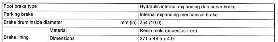
6 8-6 Master Cylinder SPECIFICATIONS 8FGCU15,18,SU20
7 8-7 COMPONENTS FRONT BRAKE Pn1 ton series 4715 Pn2 3 ton series 4715
8 8-8 Cu2 3 ton series 4715 pipe 4714
9 8-9 BRAKE MASTER CYLINDER
10 8-10 PARKING BRAKE 4601
11 8-11 BRAKE PEDAL 4701 SINGLE BRAKE PEDAL 4701
12 8-12 FRONT BRAKE DISASSEMBLY INSPECTION REASSEMBLY (Pn1, Cu2 3 TON SERIES) T = N m (kgf cm) [ft lbf] Pn1 ton series T = 7.8 ~ 11.8 (80 ~ 120) [5.8 ~ 8.68] Cu2 3 ton series T = 17.7 ~ 26.5 (180 ~ 270) [13.0 ~ 19.5] backing plate set bolt T = 137 ~ 210 (1400 ~ 2100) [101.3 ~ 154.9] Disassembly Procedure 1 Drain brake fluid. 2 Remove the front axle hub. (See page 7-8) [Point 1] 3 Remove the shoe hold down spring and cup. [Point 2] 4 Remove the anchor to shoe spring and shoe guide plate. [Point 3] 5 Remove the cable and cable guide. 6 Remove the lever strut. [Point 4] 7 Remove the adjuster spring and adjusting screw. [Point 5] 8 Disconnect the parking brake cable. [Point 6] 9 Remove the brake shoe. [Point 7] 10 Disconnect the brake pipe. 11 Remove the wheel cylinder ASSY. [Point 8] 12 Remove the backing plate. [Point 9]
13 8-13 Reassembly Procedure The reassembly procedure is the reverse of the disassembly procedure. Note: Check that the brake lining and brake drum interior surface are free from grease or oil before installation. Before reassembly, decrease the brake drum outside diameter to approx. 1 mm (0.04 in) less than the drum inside diameter by tightening the adjusting screw. After reassembly, perform brake air bleeding (see page 8-22) and braking force inspection (see page 8-22). Apply thread tightener ( ( )) to the backing plate set bolt before reassembly. Point Operations [Point 1] Inspection: Measure the brake drum inside diameter. Standard Pn1 ton series: 254 mm (10.0 in) Cu2 3 ton series: 310 mm (12.20 in) Limit Pn1 ton series: 256 mm (10.1 in) Cu2 3 ton series: 312 mm (12.28 in) Apply thread tightener ( ( )) on the brake drum set nut before reassembly. [Point 2] Disassembly SST SST Inspection: Measure the free length of the hold down spring. Standard: 25.5 mm (1.004 in)
14 8-14 Apply liquid packing ( ( )) to the shoe hold down pin and the contact surface on the back side of the backing plate to eliminate any clearance. [Point 3] Disassembly: SST ( ) SST Inspection: Measure the free length of the anchor to shoe spring. Standard Pn1 ton series: mm (4.024 in) Cu2 3 ton series: On the side of lining W/ pin mm (5.484 in) On the side of lining L/ pin mm (4.795 in) Limit: No clearance between coil turns SST SST ( ) [Point 4] Inspection: Measure the free length of the strut to shoe spring. Standard Pn1 ton series: 19.7 mm (0.776 in) Cu2 3 ton series: 29.8 mm (1.173 in)
15 8-15 [Point 5] Inspection: Measure the free length of the adjuster spring. Standard Pn1 ton series: 99.4 mm (3.913 in) Cu2 3 ton series: mm (4.961 in) Limit: No clearance between coil turns Apply grease to the adjusting screw threaded portion and fill grease in the cap. Tie a wire to the free end of the adjuster spring and set it by pulling the wire with a screwdriver. [Point 6] Apply liquid packing ( ( )) to the parking brake cable outlet of the backing plate to eliminate any clearance. [Point 7] Inspection: Measure the brake lining thickness. Standard Pn1 ton series: 4.9 mm (0.193 in) Cu2 3 ton series: 5.7 mm (0.224 in) Limit Pn1 ton series: 1.0 mm (0.039 in) Cu2 3 ton series: 1.0 mm (0.039 in) Before brake shoe installation, apply grease to the portions of the backing plate shown in the illustration (6 places in contact with the shoe rim and the anchor pin).
16 8-16 [Point 8] Inspection: Measure the clearance between the wheel cylinder and piston. Limit Pn1 ton series: mm ( in) Cu2 3 ton series: 0.15 mm ( in) Apply liquid packing ( ( )) to the backing plate fitting portion of the wheel cylinder and on the whole periphery of the set bolts to eliminate any clearance. Pn1 ton series Cu2 3 ton series [Point 9] Carefully install the backing plate set bolts because they are different in length. Apply thread tightener ( ( )) on the set bolts before reassembly. Bolt length B: l = 40 mm (1.57 in) Apply liquid packing ( ( )) to the contact surface between the backing plate and front axle bracket shown in the illustration to eliminate any clearance.
17 8-17 DISASSEMBLY INSPECTION REASSEMBLY (Pn2 3 TON SERIES) T = N m (kgf cm) [ft lbf] Wheel cylinder set bolt T = 14.7 ~ 19.6 (150 ~ 200) [10.9 ~ 14.5] backing plate set bolt T = 137 ~ 210 (1400 ~ 2100) [101.3 ~ 154.9] Disassembly Procedure 1 Drain brake fluid. 2 Remove the front axle hub. (See page 7-8.) [Point 1] 3 Remove the hold down spring. [Point 2] 4 Remove the pawl lever stopper. [Point 3] 5 Remove the pawl lever. 6 Remove the anchor to shoe spring. [Point 4] 7 Remove the strut lever. [Point 5] 8 Remove the adjuster spring and adjusting screw. [Point 6] 9 Disconnect the parking brake cable. [Point 7] 10 Remove the brake shoe. [Point 8] 11 Disconnect the brake piping. 12 Remove the wheel cylinder ASSY. [Point 9] 13 Remove the backing plate. [Point 10]
18 8-18 Reassembly Procedure The reassembly procedure is the reverse of the disassembly procedure. (With regard to steps 3 and 4, however, install the pawl lever stopper after installing the hold down spring.) Note: Check that the brake lining and brake drum interior surface are free from grease or oil before reassembly. Before reassembly, decrease the brake shoe outside diameter to approx. 1 mm (0.04 in) less than the brake drum inside diameter by tightening the adjusting screw. After reassembly, perform brake air bleeding (see page 8-22) and braking force inspection and adjustment (see page 8-22). Point Operations [Point 1] Inspection: Measure the brake drum inside diameter. Standard: 310 mm (12.20 in) Limit: 312 mm (12.28 in) Apply thread tightener ( ( )) to the brake drum set nut before reassembly. SST [Point 2] Disassembly SST Inspection: Measure the free length of the hold down spring. Standard: 34.5 mm (1.358 in) Limit: 31.3 mm (1.232 in) Apply liquid packing ( ( )) to the back side of the backing plate in contact with the shoe hold down spring to eliminate any clearance.
19 8-19 [Point 3] Inspection: Measure the free length of the actuator spring. Standard: mm (4.902 in) Limit: No clearance between coil turns Use snap ring pliers to install the pawl lever stopper and actuator spring. [Point 4] Disassembly: SST ( ) SST Inspection: Measure the free length of the anchor to shoe spring. Standard: 106 mm (4.17 in) Limit: No clearance between coil turns SST SST ( )
20 8-20 [Point 5] Inspection: Measure the free length of the strut to shoe spring. Standard: 23 mm (0.91 in) Limit: 20 mm (0.79 in) [Point 6] Inspection: Measure the free length of the adjuster spring. Standard: 86 mm (3.39 in) Limit: No clearance between coil turns Apply grease to the adjusting screw threaded portion and fill grease in the cap. [Point 7] Apply liquid packing ( ( )) to the parking brake outlet of the backing plate to eliminate any clearance. [Point 8] Inspection: Measure the brake lining thickness. Standard: 7.0 mm (0.276 in) Limit: 2.0 mm (0.079 in)
21 8-21 Apply grease to the portions of the backing plate shown in the illustration (6 places in contact with the shoe rim and the anchor pin) before brake shoe installation. [Point 9] Inspection: Measure the clearance between the wheel cylinder and piston. Limit: mm ( in) Apply liquid packing ( ( )) to the wheel cylinder backing plate fitting portion and the whole periphery of set bolts to eliminate any clearance. Pn2 ton series Pn3 ton series [Point 10] Carefully install the backing plate set bolts in the correct positions since they are different in length. Apply thread tightener ( ( )) to the set bolts before reassembly. Bolt length A: l = 36 mm (1.42 in) B: l = 40 mm (1.57 in) C: l = 45 mm (1.77 in) Apply liquid packing ( ( )) to the contact surface between the backing plate and front axle bracket shown in the illustration to eliminate any clearance.
22 8-22 Inching cable Single brake pedal spec. Inching lever BRAKE AIR BLEEDING Note: Add brake fluid to the reservoir tank during air bleeding to prevent it from becoming insufficient. When the pedal needs to be pushed all the way for air bleeding, torque converter inching cable shall be disconnect from torque converter at inching lever. (single brake pedal spec.) 1. Bleed air from the brake master cylinder. (1) Depress the brake pedal several times to compress the air in the piping, and hold that state. (2) Loosen the bleeder plug to discharge air in the piping with the brake fluid, and tighten the plug immediately before the fluid stops coming out. (3) Repeat steps (1) and (2) above until no air bubbles are seen in the discharged brake fluid. 2. Bleed air from wheel cylinders RH and LH. (1) Operate as described in step 1 above for the RH and LH side at a time. 3. Add brake fluid to the specified level. (1) Add brake fluid through the filter provided in the reservoir tank. (2) Add brake fluid up to the specified level in the reservoir tank. BRAKING FORCE INSPECTION ADJUSTMENT 1. Inspect the braking force using a brake tester or by traveling test. Braking distance (without load) Initial speed of braking km/h (mph) Max. speed Braking distance m (ft) 5.0 (16.4) or less 2. Adjust the braking force. (1) Repeat traveling in the forward and reverse directions to adjust the brake shoe clearance. The adjusting screw adjusts the clearance automatically when the brake pedal is depressed in reverse traveling. (2) If the braking force is insufficient, adjuster malfunction, lining contact defect, foreign matter adhesion on the lining or brake fluid leakage is assumed. Remove and inspect the brake drum. (3) When the brake shoe is replaced with a new one, repeat traveling in the forward and reverse directions for running in.
23 8-23 BRAKE MASTER CYLINDER REMOVAL INSTALLATION T = N m (kgf cm) [ft lbf] 7 T=6.8~15.8 (69~161) [5.0~11.7] LBC Removal Procedure 1 Remove the lower panel. 2 Remove the toe board. 3 Remove the instrument panel. 4 Remove the column cover. 5 Disconnect the brake side hose from the reservoir tank and drain brake fluid. 6 Disconnect the piping. 7 Remove the push rod clevis pin. 8 Remove the brake master cylinder. Installation Procedure The installation procedure is the reverse of the removal procedure. Note: After installation, perform brake pedal adjustment (see page 8-27) and air bleeding (see page 8-22).
24 8-24 DISASSEMBLY INSPECTION REASSEMBLY Disassembly Procedure 1 Turn the boot up and remove the snap ring. 2 Remove the push rod. [Point 1] 3 Remove the piston. [Point 2] 4 Remove the pin and the fluid inlet elbow. 5 Remove the outlet plug and valve. Reassembly Procedure The reassembly procedure is the reverse of the disassembly procedure.
25 8-25 Point Operations [Point 1] Temporarily set the push rod length to the illustrated dimension, and make readjustment after installation. 130 mm (5.118 in) [Point 2] Apply rubber grease to the piston cup and whole periphery of the cup before reassembly.
26 8-26 A PARKING BRAKE INSPECTION ADJUSTMENT 1. Check the parking brake cable set position. Standard: A = 0 ~ 2 mm (0 ~ 0.08 in) 2. Apply chassis grease to the portions indicated by arrows. LH When using the SST RH (A) 3. Inspect and adjust the parking brake pedal operating force. (1) Set the SST to the parking brake pedal. SST (2) Set a spring scale to the SST and pull it backward to measure the operating force. SST When not using the SST (B) Standard: (A) When using the SST 112 ~ 136 N (11.4 ~ 13.9 kgf) [25.1 ~ 30.6 lbf] (B) When not using the SST 186 ~ 226 N (19 ~ 23 kgf) [42 ~ 51 lbf] (3) If the operating force is out of the standard range, release the parking brake and make adjustment at the adjusting portion. Clockwise turn: Increases the operating force. Counterclockwise turn: Decreases the operating force. RELEASE LEVER CABLE ADJUSTMENT 1. Adjust the play of the release lever to 0 to 5 mm (0 to 0.2 in) at the tip of the lever using the release cable adjusting nut. Adjusting nut Release lever
27 8-27 BRAKE PEDAL INSPECTION ADJUSTMENT Stop lamp switch master cylinder C A Reference value 135 ~ 140 mm (5.315 ~ in) D (11.0 mm (0.433 in)) Push rod B Toe board Floor mat 1. Inspect brake pedal height A. (From toe board to top of pedal) Standard: A = 145 ~ 150 mm (5.91 ~ 6.10 in) (with pedal pad) If the standard is not satisfied, make adjustment by changing the stop lamp switch position. 2. Inspect brake pedal play B. Standard: B = 1 ~ 5 mm (0.039 ~ in) If the standard is not satisfied, make adjustment by changing the master cylinder push rod length. 3. Check master cylinder push rod play C with the brake pedal in the above state. Standard: C = 1 mm (0.04 in) 4. After the adjustment, fully depress the brake pedal and inspect pedal height D. Standard: D = 90 mm (3.54 in) or more
28 8-28 INCHING PEDAL INSPECTION ADJUSTMENT pedal link Stopper bolt Inching pedal plate Adjusting nut B A C Floor mat (135 ~ 140 mm (5.315 ~ in)) (145 ~ 150 mm (5.709 ~ in)) Toe board Adjusting nut Inching lever 1. Inspect and adjust the brake pedal height and play (See page 8-27). 2. Inspect stroke A of the inching pedal until interlocking with the brake (pedal stroke until the inching pedal plate comes into contact with the brake link). Standard Pn1 ton series: A = 35 ~ 41 mm (1.38 ~ 1.61 in) Others: A = 26 ~ 32 mm (1.02 ~ 1.26 in) If the standard is not satisfied, adjust the stopper bolt protrusion. Adjust the brake pedal height within + 15 mm (0.59 in). 3. Inspect and adjust the inching cable. (1) Inspect inching cable length B on the pedal side. Standard: B = 17.5 mm (0.689 in) If the standard is not satisfied, adjust it by turning the adjusting nuts on the pedal side. (2) Inspect inching pedal play C before the inching lever starts to move. Standard: C = 1 ~ 3 mm (0.04 ~ 0.12 in) If the standard is not satisfied, adjust it by turning the adjusting nuts on the inching lever side.
29 8-29 SINGLE BRAKE (INCHING) PEDAL INSPECTION ADJUSTMENT (1-PEDAL: OPT) Adjusting bolt Stopper bolt Inching pedal No gap (a) pedal plate link Push rod Adjusting nut B A C Floor mat 130 ~ 135 mm (5.118 ~ in) 140 ~ 145 mm (5.512 ~ in) 11 mm (0.433 in) Toe board Adjusting nut Inching lever 1 Tighten the adjusting bolt until there is no gap between the adjusting bolt and surface (a) of the inching pedal, and tighten the lock nut. 2 Adjust the height and play of the pedal. The values specified in the above illustration should be used as the standard for the pedal height. Refer to page 8-27 for adjustment method. 3. Inspect stroke A of the pedal until interlocking with the brake (pedal stroke until the pedal plate and bolt head comes into contact with the brake link). Standard Pn1 ton series: A = 41.7 ~ 48.7 mm (1.64 ~ 1.92 in) Others: A = 29.7 ~ 36.7 mm (1.17 ~ 1.44 in) If the standard is not satisfied, adjust the stop lamp switch or stopper bolt protrusion. 4. Inspect and adjust the inching cable. (1) Inspect the inching cable length B on the pedal side. Standard: B = 17.5 mm (0.689 in) If the standard is not satisfied, make adjustment by turning the adjusting nuts on the pedal side. (2) Inspect inching pedal play C until the torque converter inching lever starts to move. Standard: C = 1 ~ 3 mm (0.04 ~ 0.12 in) LBC If the standard is not satisfied, make adjustment by turning the adjusting nuts on the torque converter side.
30 8-30 WET BRAKE GENERAL Front A A A-A
31 8-31 Parking Pn2, Cu2, Cu3 ton series Pn3 ton series Accumulator WARNING: It contains nitrogen under high pressure. Don t allow fire or heat near it. Don t try to disassemble it. Wear eye protection and carefully drill a hole at the point marked to release GAS pressure before disposal.
32 8-32 Flow Divider Valve (for Cooling System) Check Valve Relief Valve IN OUT
33 8-33 Valve From accumulator To front brake From oil pump To oil tank Pressure testing opening To PS valve SPECIFICATIONS Item Foot brake Parking brake valve Type lining dimensions (Thickness x Outside diameter x Inside diameter) Model mm (in) Pn2 series Pn3 series Cu2 series Cu3 series Wet disc brake 2.0 x 260 x 198 (0.08 x x 7.80) Number of discs 5 discs 6 discs 4 discs 5 discs Type Mechanical disc brake lining dimensions (Thickness x Outside diameter x Inside diameter) Number of discs Type mm (in) 1.6 x 112 x 84 (0.06 x 4.41 x 3.31) 7 disc Full power CHPS Input piston outside diameter mm (in) 25.4 (1.0) Input piston stroke mm (in) 12.7 (0.5) Maximum hydraulic pressure Mpa (kgf/cm 2 ) 7.8 (79.5) [1131] Oil used Hydraulic oil ISO VG32 Cooling oil SHELL DONAX TD Cooling oil capacity I (USgal) 7.8 ~ 8.2 (2.1 ~ 2.2) 7.2 ~ 7.6 (1.9 ~ 2.0)
34 8-34 HYDRAULIC CIRCUIT DIAGRAM operation system PS valve valve Flow divider valve Oil control valve Wet brake Orifice Check valve Oil tank Relief valve Accumulator Warning buzzer & lamp cooling system Relief valve Flow divider valve cooling oil tank Wet brake LH Oil cooler Engine Torque converter & transmission Front axle Oil pump Relief valve Wet brake RH
35 8-35 COMPONENTS Parking 4601 Pedal 4701
36 8-36 Valve 4704 Accumulator 4706
37 8-37 Piping
38 8-38 Cheak Valve 4714 ASSY 4715
39 8-39 FRONT BRAKE ASSY DISASSEMBLY INSPECTION REASSEMBLY Note: Depressurize the accumulator before starting the operation (Refer to 8-46) T = N m (kgf cm) [ft lbf] Pn2 3 T = 137 ~ 210 (1400 ~ 2100) [101 ~ 155] Cu2 3 T = 90 ~ 120 (900 ~ 1200) [66 ~ 89] 3 2 T = 44.1 ~ 59.8 (450 ~ 610) [32.5 ~ 44.1] Disassembly Procedure 1 Remove the front axle hab. (see page XX-XX) 2 Remove the bushing. (except for Cu2 ton series) [Point 1] 3 Remove the ASSY. [Point 2] 4 Remove the inner housing. [Point 3] 5 Remove the plate No.2 and the spring. [Point 4] 6 Remove the plate No.1 and the brake disk [Point 5] 7 Remove the snap ring and oil seal. 8 Remove the piston and piston seal. [Point 6] 9 Remove the pressure plate and steel balls. [Point 7] 10 Remove the cam, lever, adjusting bolt and O-ring. Reassembly Procedure The reassembly procedure is reverse of the disassembly procedure.
40 8-40 Note: After reassembly, perform brake air bleeding. (see page 8-46) After reassembling, check the operation of the accumulator. (see page 8-55) During reassembling, check that no foreign matter is attached to the parts. SST (2) Point Operations [Point 1] Removal: SST (1) ( ) (2) ( ) SST (1) Except Cu3 ton series A Cu3 ton series Installation: Use a copper bar to reassemble the bushing into the position A in the drawing. Standard Except Cu3 ton series: A = 0 ~ 1 mm (0 ~ in) Cu3 ton series: Press the bush in until it contacts the axel housing. Pn2 Pn3 ton series Cu2 Cu3 ton series [Point 2] Apply a sealant ( ( )) to the contact surface of the brake assembly and front axel bracket, and reassemble them. Pn2 3 ton series Check the brake cooling oil hole, and assemble the O ring between the brake assembly and front axel bracket. Cu2 3 ton series Cooling oil hole
41 8-41 [Point 3] Reassemble the brake assembly in the following procedure. 1. Raise the housing by placing wooden blocks under the outer housing, taking care not to press on the oil seal. 2. Place the brake discs and plates No.1 alternately in the housing. 3. Reassemble the springs (6 pieces). 4. Align the plate No. 2 with the groove in the outer housing. 5. Hand tighten the housing set bolt and nut, and set the inner housing so that it floats up by the power of the springs. 6. Press the inner housing by hand to check that it seals. If it cannot be pressed to seal by hand, then plate No. 2 is not in the correct position. Carry out step 4 again. 7. Reassemble the housing set bolt and nut to the standard tightening torque. SST Use the SST to arrange the engagement of the gears of the brake disc, plate No. 1, and plate No. 2. SST After engaging the gears, tighten the adjusting bolt to fix the disc. [Point 4] Inspection: Measure the thickness of plate No. 2. Standard: 3.6 mm (0.142 in) Limit: XX mm (XX in)
42 8-42 Inspection: Measure the free length of the spring. Standard: 25.7 mm (1.012 in) Limit: 23.7 mm (0.933 in) [Point 5] Inspection: Measure the thickness of plate No. 1. Standard: 2.0 mm (0.079 in) Limit: 1.7 mm (0.067 in) Inspection: Measure the thickness of the brake disc. Standard: 35 mm (0.138 in) Limit: 3.2 mm (0.126 in)
43 8-43 Service tab [Point 6] Disassembly: When removing the brake piston, remove it using the 2 service tabs (M6 x 1.0). Piston seal Reassemble the brake piston in the following procedure. 1. After applying hydraulic oil to the piston seal, reassemble it to the housing by hand. Use gloves at this time. Piston seal 2. Prepare 3 box wrenches of equal height as a holder on which to place the housing. 3. Set the 3 box wrenches in contact with the flat face in the center of the housing, and set on a hand press. 4. Apply hydraulic oil to the contact surface of the piston seal by hand. Use gloves at this time.
44 Place the piston on the insertion face, and place a round plate or strong metal plate such as is shown in the drawing on top of the piston. Use a hand press to slowly insert the piston. When the operation of the hand press becomes heavy, stop the operation. Pressure plate [Point 7] When reassembling the pressure plate, check that the steel balls (3 balls) are assembled in the grooves of the inner housing and pressure plate before inserting the pressure plate. Steel ball
45 8-45 DEPRESSURIZING THE ACCUMULATOR 1. With the engine stopped. Depress the brake pedal fully to its stroke end. Depress it 100 times or more. BRAKING POWER INSPECTION 1. Inspect the braking power using a brake tester or by a driving test. Braking stop distance (in unloaded condition) Braking initial speed Maximum speed Stopping distance 5.0 m (196.9 in) or less PURGING THE AIR FROM THE BRAKE 2. When the braking power is insufficient, carry out the following inspections. Purge the air from the brake assembly in the following procedure. 1. Loosen the air purging breather plug on the brake assembly on one side. 2. Connect an air purging hose to the loosened breather plug. 3. Start the engine, and depress the brake pedal. (Until air stops coming out from the air purging hose) 4. Tighten the breather plug, and remove the air purging hose. Tightening torque: 7.0 ~ 12.0 N m (71.4 ~ kgf cm) [5.2 ~ 8.9 ft lbf] 5. Carry out the operations 1-4 above for the brake assembly on the other side. (1) piping oil leakage inspection. (2) valve operation inspection. (3) If the brake disk is replace with a new part, drive forward and backward repeatedly to break the new disk in.
46 8-46 Bolt B Lock nut Bolt A Bolt A POINTS FOR LOCKING THE BRAKE DISK - PLATE NO. 1 - PLATE NO. 2 Note: When detaching the front axel hub, the brake disk can be temporarily locked so that the brake disk serrations do not slip out of alignment. The brake disk - plate No.1 - and plate No.2 are locked in the following procedure. 1. Loosen bolt A. 2. Loosen the lock nut. 3. Tighten bolt B until the adjusting lever comes into contact with the disk plate. At this point, make a note of the number of turns taken to tighten the bolt B. 4. Temporarily tighten bolt A. 5. To unlock the brake disc, reverse this procedure. Note: When the tightening dimension of the bolt B in point 3, is not clear, or when bolt A is close to the end of the long hole in the lever when bolt B is tightened, the disk may be worn. Adjust the brake disk gap. (Refer to page 8-48)
47 8-47 ADJUSTING THE BRAKE DISK GAP Note: Wear of the brake disk causes an increase in the brake piston stroke that affects the life of the brake. Therefore, the brake disk clearance should be adjusted every year (once a year (once every 2000H)). SST Union 1. Remove the lower panel and toe board. 2. Remove the plug in the pressure testing opening of the brake valve, attach the union there, then attach an oil pressure meter via the SST. Union SST With the engine stopped, depress the brake pedal and hold it in the position at which the oil pressure reaches the value below. Hold it in position either by having somebody step on it, or by fixing it in place with rope etc. Pedal holding standard pressure: 1.0 MPa (10 kgf/cm 2 ) [140 psi] Bolt B Lock nut X Bolt A 4. Loosen the adjusting lever set bolt A, tighten the bolt B until the adjusting lever comes into contact with the disk plate, then tighten the bolt A temporarily. 5. In the status described in 3., adjust the bolt B until the clearance X between the tip of bolt B and the adjusting lever equals the value below, then fix bolt B with the lock nut. Clearance X = 2.47 ~ 2.73 mm (0.097 ~ in) Note: A clearance of X = 2.6 mm (0.102 in) corresponds to a brake disk clearance of 0.5 mm (0.020 in). 6. Loosen the temporarily tightened bolt A, check that the adjusting lever makes contact with the bolt B, then tighten the bolt A to the correct torque. Tightening torque for bolt A T = 13.7 ~ 22.6 N m (139.7 ~ kgf cm) [10.1 ~ 16.7 ft lbf]
48 8-48 BRAKE VALVE REMOVAL INSTALLATION Note: Depressurize the accumulator before starting the operation (Refer to page 8-46) T = N m (kgf cm) [ft lbf] T = (~) [~] T = 6.8~15.8 (69~161) [5.0~11.7] 8 Removal Procedure 1 Remove the lower panel. 2 Remove the toe board. 3 Remove the instrument panel. 4 Remove the column cover. 5 Disconnect the piping. 6 Remove the clevis pin of the push rod. 7 Remove the brake valve W/bracket. 8 Remove the bracket. Installation Procedure The installation procedure is the reverse of the removal procedure. Note: After installing, adjust the brake pedal (Refer to page 8-65) and purge the air (Refer to page 8-46). After installing check the operation of the accumulator. (Refer to page 8-55)
49 8-49 DISASSEMBLY INSPECTION REASSEMBLY Note: All components are machined to a high-precision finish. Be careful not to damage them while working. Conduct the work in a clean location. T = N m (kgf cm) [ft lbf] 3 T = 49.0 ~ 78.5 (500 ~ 800) [36.2 ~ 57.9] T = 67.7 ~ (690 ~ 1100) [49.9 ~ 79.6] 7 Disassembly Procedure 1 Remove the push rod. 2 Remove the boots. 3 Remove the lock nut, snap ring, and plate washer. [Point 1] 4 Remove the input piston and compression spring. [Point 2] 5 Remove the cylinder cap from the input piston. [Point 3] 6 Remove the hole plug. 7 Remove the closed valve, valve return spring, and spring retainer. [Point 4] 8 Remove the reaction piston guide W/reaction piston and the brake valve spool. 9 Remove the reaction piston guide. 10 Remove the reaction piston. Reasssembly Procedure The reassembly procedure is the reverse of the disassembly procedure. Note: Carefully clean all components, blow them off with compressed air to remove dirt, coat them with hydraulic oil, and then reassembly them. Apply silicon grease to the cylinder cap and then reinstall the cap. Apply MP grease to the end of the push rod.
50 8-50 Point Operations [Point 1] Adjust the input piston stroke. 1. Install the plate washer. 2. Place the snap ring onto the input piston. 3. Screw on the lock nut and adjust the input piston stroke. Standard: A = 12.7 ± 1.0 mm (0.5 ± in) A 4. Tighten the lock nuts. 5. Reinstall the snap ring. Inspection: After reassembly, check the brake hydraulic pressure. (See page 24-56) When lower than the standard value: Enlarge dimension A. When higher than the standard value: Decrease dimension A. [Point 2] Inspection: Measure the free length of the compression spring. Standard: 21mm (0.83 in) Limit: 18.9mm (0.744 in) [Point 3] Make sure the cylinder cap is reinstalled in the correct orientation. SST SST [Point 4] Inspection: Measure the free length of the valve return spring. Standard: 21.9mm (0.862 in) Limit: 19.7mm (0.776 in)
51 8-51 BRAKE VALVE OPERATION INSPECTION SST Union 1. Remove the lower panel and toe board. 2. Depressurize the accumulator. (Refer to page 8-46) 3. Remove the plug in the pressure testing opening of the brake valve, attach the union there, then attach an oil pressure meter via the SST. Union SST With the engine idling, measure the oil pressure when the brake pedal is fully depressed to the stroke end. MPa (kgf/cm 2 ) [psi] Vehicle model Standard 2 ton class 5.9 ~ 6.9 (60.2 ~ 70.4) [855.5 ~ ] 3, J3.5 ton class 6.9 ~ 7.9 (70.4 ~ 80.6) [ ~ ] 5. Raise the engine idle speed to 1000 rpm, turn the steering left and right until full lock 4-5 times to build maximum pressure in the accumulator, then cut the engine. 6. With the engine stopped, measure the oil pressure when the brake pedal is fully depressed to the stroke end. MPa (kgf/cm 2 ) [psi] Vehicle model Standard 2 ton class 5.0 (51.0) [725.0] or more 3, J3.5 ton class 5.5 (56.1) [797.5] or more
52 8-52 ACCUMULATOR ASSY REMOVAL INSTALLATION Note: Depressurize the accumulator before starting the operation. (Refer to page 8-46) T = N m (kgf cm) [ft lbf] T = 32.4 ~ 48.6 (330 ~ 500) [23.9 ~ 35.9] Removal Procedure 1 Remove the front under cover and rear under cover. 2 Remove the lower panel and toe board. 3 Disconnect the wiring. 4 Remove the propeller shaft cover set bolt. 5 Disconnect the piping. 6 Remove the accumulator ASSY. Installation Procedure The installation procedure is the reverse of the removal procedure. Note: After installation, bleed air from the brake. (Refer to page 8-46) After installing check the operation of the accumulator. (Refer to page 8-55)
53 DISASSEMBLY INSPECTION REASSEMBLY 8-53 T = N m (kgf cm) [ft lbf] 1 T = 39 ~ 45 (400 ~ 460) [28.8 ~ 33.2] 1 T = 39 ~ 45 (400 ~ 460) [28.8 ~ 32.2] T = 17.5 ~ 22.5 (180 ~ 230) [12.9 ~ 16.6] T = 100 ~ 136 (1000 ~ 1400) [73.8 ~ 100.3] 2 T = 39 ~ 45 (400 ~ 460) [28.8 ~ 32.2] 3 T = 28 ~ 42 (300 ~ 400) [20.7 ~ 31.0] Disassembly Procedure 1 Remove the fitting, pressure switch, and check valve. 2 Remove the relief valve. 3 Remove the accumulator. Installation Procedure The installation procedure is the reverse of the removal procedure.
54 8-54 ACCUMULATOR INSPECTION SST Union Function inspection 1. Remove the lower panel and toe board. 2. Depressurize the accumulator. (Refer to page 8-46) 3. Remove the plug in the pressure testing opening of the brake valve, attach the union there, then attach an oil pressure meter via the SST. Union SST Raise the engine idle speed to 1000 rpm, turn the steering left and right until full lock 4-5 times to build maximum pressure in the accumulator, then cut the engine. 5. With the engine stopped. Depress the brake pedal fully to its stroke end, then release it. Wait 30 seconds, then depress and release the pedal again. 6. After repeating item 5 ten times, inspect the oil pressure when the pedal is depressed for the 11th time. Standard: 3.3MPa (33.7Kgf/cm 2 ) [478.5 psi] or more Note: If it is outside the standard, replace the accumulator. 7. With the engine stopped, depress the brake pedal fully to the stroke end, and hold it like this for 10 minutes. Check that the difference in the pressure values at the time when the pedal is first depressed, and at 10 minutes afterwards is zero. Note: If there is a difference in the pressures, clean the check valve and relief valve, check for damage to the seat part, and if there are no abnormalities, replace the part. Accumulator alarm inspection (Export model) 1. Raise the engine idle speed to 1000 rpm, turn the steering left and right until full lock 4 ~ 5 times to build maximum pressure in the accumulator, then cut the engine. 2. With the engine stopped, turn the key to the ACC position, depress the brake pedal fully to its stroke end, then release it. 3. Repeat 2., and inspect the pressure at which the alarm sounds. Alarm starts: 3.7 ~ 4.1MPa (37.7 ~ 41.8kgf/cm 2 ) [536.5 ~ psi] 4. Once the alarm has sounded, start the engine, and with the engine idling, depress the brake pedal and inspect the pressure at which the alarm stops. Alarm stops: 4.7 ~ 5.5MPa (47.9 ~ 56.1kgf/cm 2 ) [681.5 ~ psi]
55 8-55 PARKING BRAKE ASSY DISASSEMBLY INSPECTION REASSEMBLY T = N m (kgf cm) [ft lbf] 2 T = 32.4 ~ 48.6 (330 ~ 500) [23.9 ~ 35.9] 4 6 T = 13.7 ~ 25.4 (140 ~ 260) [10.1 ~ 18.7] Disassembly Procedure 1 Remove the front axle & differential ASSY. (see page 4-12) 2 Remove the rear cover. 3 Remove the brake disc, plate No.2 and plate No.1. [Point 1] 4 Remove the retainer. 5 Remove the stopper bolt bracket, fork, and shaft. [Point 2] 6 Remove the oil seal. [Point 3] Reassembly Procedure The reassembly procedure is the reverse of the disassembly procedure. Note: During reassembling, check that no foreign matter is attached to the parts.
56 8-56 Point Operations [Point 1] Inspection: Measure the thickness of plate No.1. Except Pn3 ton series Standard: 1.2 mm (0.047 in) Limit: 1.0 mm (0.039 in) Pn3 ton series Standard: 1.5 mm (0.059 in) Limit: 1.3 mm (0.051 in) Inspection: Measure the thickness of plate No.2. Except Pn3 ton series Standard: 9.0 mm (0.354 in) Limit: 8.8 mm (0.35 in) Pn3 ton series Standard: 9.5 mm (0.374 in) Limit: 9.3 mm (0.366 in) Inspection: Measure the thickness of the brake disc. Standard: 1.6 mm (0.063 in) Limit: 1.2 mm (0.047 in) Align the notches in the brake disk and the reduction gear and reassemble them. (Pn2, Cu2 3 ton series) Notch
57 8-57 Hole Align the positions of the holes in the brake discs and reassemble them. (Pn3 ton series) Hole Fork [Point 2] Align the punch marks in the fork and shaft to reassemble them. Punch Marks Engage the spline so that the lever is vertical when the fork is level. Fork level If the spline engagement of the fork and shaft is out by one tooth, the result will be as shown in the drawing to the left. (Reference) A [Point 3] Using a pin, tap the new oil seal in from the edge of the rear cover to the position A. Standard: A = 5.0 ~ 5.5 mm (0.20 ~ 0.22 in) After reassembly, apply MP grease to the lip section of the oil seal.
58 8-58 PARKING BRAKE FUNCTION INSPECTION Checking the operation of the parking brake warning alarm (Export model) and pilot lamp If the parking brake warning alarm and pilot lamp do not operate as below, adjust the parking switch. 1. Check that the light turns on when the parking pedal is depressed. 2. Check that the light turns off when the parking pedal is released. 3. When travelling at 1.2 mph (2 km/h) without releasing the parking pedal, the alarm sounds. 4. When leaving the dirving seat without locking the parking pedal, the alarm sounds. (Export model) 50 ~ 100 N (5.1 ~ 10.2 kgf) [11 ~ 22 ft] Parking brake lever Stopper Bolt ADJUSTING THE PARKING LEVER SWITCH 1. After reassembling the disk, pull the end of the parking brake lever and adjust the clearance A between the tip of the stopper bolt and the parking brake lever. Lock the stopper bolt with the nut. A = 3.0 ~ 3.6 mm (0.12 ~ 0.14 in) Parking brake lever Stopper Bolt 2. The parking brake limit switch can be adjusted by the following procedure. (1) Insert a 0.5 mm (0.02 in) thickness gauge between the stopper bolt and parking brake lever. 0.5 mm (0.02 in) Switch end Bolt for switch (2) Bring the bolt for the switch into contact with the switch end, and lock the bolt for the switch with a lock nut, in the position where the switch is ON. (3) Insert a 1.5 mm (0.059 in) thickness gauge between the stopper bolt and the lever, and check that the switch turns OFF. 1.5 mm (0.059 in)
59 8-59 A PARKING BRAKE INSPECTION AND ADJUSTMENT 1. Check the set position of the parking brake cable. Standard: A = 0 ~ 2 mm (0 ~ in) 2. Apply chassis grease to the points indicated by arrows in the illustration. For LH For RH When using SST (A) SST 3. Inspect and adjust the operating force of the parking brake pedal. (1) Attach the SST to the pedal. SST (2) Attach a spring balance to the SST, and pull the reverse end to measure the operation force. When not using SST Standard: (A) When using the SST 112 ~ 136 N (11.4 ~ 14.0 kgf) [25.1 ~ 30.6 lbf] (B) When not using the SST 185 ~ 225 N (19.0 ~ 23.0 kgf) [42.0 ~ 51.0 lbf] (B) (3) If the operation force is outside of the standard, release the parking brake and adjust with the adjusting part. Clockwise: Strong operation force Counter clockwise: Weak operation force ADJUSTING THE RELEASE LEVER CABLE 1. Use the release cable adjust nut to adjust so that the play at the tip of the release lever is about 0 ~ 5 mm (0 ~ in). Adjust nut Release lever
60 8-60 BRAKE COOLING OIL TANK REMOVAL INSTALLATION T = N m (kgf cm) [ft lbf] T = 000 ~ 000 (000 ~ 000) 6 Removal Procedure 1 Remove the lower panel and toe board. 2 Remove the under cover. 3 Drain the brake cooling oil. (Refer to page 8-63) 4 Disconnect the piping. 5 Remove the brake cooling oil tank. 6 Remove the oil filter and fitting. [Point 1] Installation Procedure The installation procedure is the reverse of the removal procedure. Point Operations [Point 1] Inspection: Inspect and clean the oil filter.
61 8-61 PROCEDURE FOR POURING IN BRAKE COOLING OIL 1. Pour 4.8 l (1.27 US gal) into the tank. 2. Start the engine and allow the brake cooling oil to fill inside the brakes. 3. Pour brake cooling oil into the tank again, checking the amount on the level gauge. Inspect the oil amount by putting the level gauge cap part on the top end of the lubrication hole. (Do not push the cap part into the lubrication hole). cooling oil amount for each part (guide) Oil to be used: Shell Donax TD Oil amount l (US gal) Inside tank 4.8 (1.27) Piping 0.8 (0.211) Inside the brake 1.6 (0.422) Inside the cooler 0.8 (0.211) Total 8.0 (2.112)
62 8-62 BRAKE COOLING OIL COOLER REMOVAL INSTALLATION T = N m (kgf cm) [ft lbf] Removal Procedure 1 Remove the radiator cover. 2 Remove the counter weight. 3 Drain the oil inside the brake cooling oil cooler. (Refer to page 8-63) 4 Disconnect the piping. 5 Remove the brake cooling oil cooler. Installation Procedure The installation procedure is the reverse of the removal procedure.
63 8-63 BRAKE PEDAL INSPECTION AND ADJUSTMENT Stop lamp switch A Reference value 135 ~ 140 mm (5.31 ~ 5.51 in) D (11.0 mm (0.43 in)) B Toe board Floor mat 1. Inspect the brake pedal height A. (From the toeboard to the upper surface of the pedal) Standard: A = 145 ~ 150 mm (5.71 ~ 5.91 in) (with pedal pad) If outside of the standard, adjust with the projection amount of the stopper lamp switch. 2. Inspect the brake pedal play B. Standard: B = 1 ~ 5 mm (0.039 ~ in) If outside of the standard, adjust with the brake valve push rod length. 3. After adjusting, depress the brake pedal fully, and check the remaining depression margin D. Standard: D = 90 mm (3.54 in) or more
64 8-64 INCHING PEDAL INSPECTION AND ADJUSTMENT pedal link Adjusting nut B A Stopper bolt C Inching pedal plate Floor mat (135 ~ 140 mm (5.31 ~ 5.51 in)) (145 ~ 150 mm (5.71 ~ 5.91 in)) Toe board Adjusting nut Inching lever 1. Inspect and adjust the height and play of the brake pedal. (Refer to page 8-65) 2. Inspect the stroke A until the inching pedal links with the brake (the pedal stroke amount until the inching pedal plate contacts with the brake link). Standard: A = 26 ~ 36 mm (1.02 ~ 1.26 in) If outside of the standard, adjust with the projection amount of the stopper bolt. Here, adjust so that the shift in the height of the brake pedal is within 15 mm (0.59in). 3. Inspect and adjust the inching cable. (1) Inspect the set dimension B of the inching cable on the pedal side. Standard: 17.5 mm (0.689 in) If outside of the standard, adjust with adjusting nut on the pedal side. (2) Inspect the play C of the inching pedal until the inching lever starts to move. Standard: C = 1 ~ 3 mm (0.04 ~ 0.12 in) If outside of the standard, adjust with adjusting nut on the inching lever side.
65 8-65 INSPECTION AND ADJUSTMENT OF THE SINGLE BRAKE (INCHING) PEDAL Adjusting bolt Inching pedal No Clearance (a) pedal plate link Push rod Adjusting nut B Stopper bolt A C Floor mat (140 ~ 145 mm (5.51 ~ 5.71 in)) (150 ~ 155 mm (5.91 ~ 6.10 in)) Toe board (11 mm (0.43 in)) Adjusting nut Inching lever 1. Tighten the adjusting bolt until the clearance between the side (a) of the inching pedal and the tip of the adjustment bolt is gone, then lock it with the lock nut. 2. Adjust the pedal height and play. Use the standard value on this page for the pedal height, and refer to page 8-65 for the adjustment method. 3. Inspect the stroke A until the inching pedal links with the brake (the pedal stroke amount until the inching pedal plate contacts with the brake link). Standard: A = 61.7 ~ 68.6 mm (2.43 ~ 2.70 in) If outside of the standard, adjust with the push rod length. 4. Inspect and adjust the inching cable. (1) Inspect the set dimension B of the inching cable on the pedal side. Standard: B = 17.5 mm (0.69 in) If outside of the standard, adjust with adjusting nut on the pedal side. (2) Inspect the play C of the inching pedal until the inching lever starts to move. Standard: C = 1 ~ 3 mm (0.039 ~ in) If outside of the standard, adjust with adjusting nut on the inching lever side.
66 8-66 GREASING TO PARKING BRAKE PEDAL RELEASE PIN After servicing the parking brake pedal, and every year or every 2000 hours, apply grease (molybdenum disulfide grease) to parking brake pedal release pin. Release pin
Symptom Suspect Area See page 5. Engine mounting (Loosen) 6. Clutch disc assy (Runout is excessive) 7. Clutch disc assy (Oily)
 6. Clutch disc assy (Runout is excessive) 7. Clutch disc assy (Oily)") CLUTCH CLUTCH SYSTEM (MTM) PROBLEM SYMPTOMS TABLE HINT: CLUTCH SYSTEM (MTM) Use the table below to help you find the cause of the problem. The numbers indicate the priority of the likely cause of the problem.
CLUTCH CLUTCH SYSTEM (MTM) PROBLEM SYMPTOMS TABLE HINT: CLUTCH SYSTEM (MTM) Use the table below to help you find the cause of the problem. The numbers indicate the priority of the likely cause of the problem.
BRAKE SYSTEM Return To Main Table of Contents
 BRAKE SYSTEM Return To Main Table of Contents GENERAL... 2 BRAKE PEDAL... 10 MASTER CYLINDER... 13 BRAKE BOOSTER... 16 BRAKE LINE... 18 PROPORTIONING VALVE... 19 FRONT DISC BRAKE... 20 REAR DRUM BRAKE...
Part Name. TOYOTA electrical tester. Engine sling device. Crankshaft pulley replacer. Belt tension gage. Connecting rod bushing remover & replacer
 16-2 SST LIST Illustration Part No. Part Name Section : Newly adopted SST 1 2 4 5 6 7 8 11 12 13 14 15 09082-76002-71 (09082-00050) TOYOTA electrical tester 09090-76002-71 (09090-04020) Engine sling device
OVERHAUL NOTICE: 7. REMOVE BRAKE MASTER CYLINDER (a) Disconnect the 5 connectors from brake master cylinder.
 Disconnect the 5 connectors from brake master cylinder.") OVERHAUL Before starting the work, make sure that the ignition switch is OFF and depress the brake pedal more than 40 times. HINT: When a pressure in power supply system is released, reaction force become
OVERHAUL Before starting the work, make sure that the ignition switch is OFF and depress the brake pedal more than 40 times. HINT: When a pressure in power supply system is released, reaction force become
2010 Toyota Prius Repair Manual
 REMOVAL 1. DISABLE BRAKE CONTROL (a) Wait at least 2 minutes after the power switch off. NOTICE: When the brake pedal is depressed or the door courtesy switch is turned on even if the power switch is off,
12. FRONT WHEEL/FRONT BRAKE/
 12 4.5kgm 0.9kg-m 4.5kg-m 12-0 SERVICE INFORMATION... 12-1 HYDRAULIC BRAKE... 12-10 TROUBLESHOOTING... 12-2 FRONT SHOCK ABSORBER... 12-16 FRONT WHEEL... 12-3 STEERING HANDLEBAR... 12-19 FRONT BRAKE...
Brake System H TX, H2.0TXS [B475]; H TX [B466] Safety Precautions Maintenance and Repair
![Brake System H TX, H2.0TXS [B475]; H TX [B466] Safety Precautions Maintenance and Repair](/thumbs/86/93834005.jpg "Brake System H TX, H2.0TXS [B475]; H TX [B466] Safety Precautions Maintenance and Repair") HMM180001 Brake System H1.5-1.8TX, H2.0TXS [B475]; H2.5-3.5TX [B466] Safety Precautions Maintenance and Repair When lifting parts or assemblies, make sure all slings, chains, or cables are correctly fastened,
HMM180001 Brake System H1.5-1.8TX, H2.0TXS [B475]; H2.5-3.5TX [B466] Safety Precautions Maintenance and Repair When lifting parts or assemblies, make sure all slings, chains, or cables are correctly fastened,
OVERHAUL. Remove the union bolt and a gasket from the disc brake cylinder, then disconnect the flexible hose from the disc brake cylinder.
 OVERHAUL COMPONENTS: See page 3232 Overhaul the RH side by the same procedures with LH side. Two types of brake pad exist; one is with slit and the other without slit. 1. REMOVE REAR WHEEL 2. DRAIN FLUID
This file is available for free download at
 This file is available for free download at http://www.iluvmyrx7.com This file is fully text-searchable select Edit and Find and type in what you re looking for. This file is intended more for online viewing
ILLUSTRATION ILLUSTRATION
 ILLUSTRATION ILLUSTRATION REMOVAL 1. DISABLE BRAKE CONTROL (a) Wait at least 2 minutes after the power switch off. When the brake pedal is depressed or the door courtesy switch is turned on even if the
1. General Description
 General Description 1. General Description A: SPECIFICATION Front disc brake Rear disc brake Master cylinder Brake booster Brake line Model Other models WRX MT WRX AT STi Size 15 inch type 16 inch type
CLUTCH PREPARATION Union Nut Wrench 10 mm Clutch Guide Tool Input Shaft Front Bearing Puller
 CLUTCH CL1 CL2 PREPARATION SST (SPECIAL SERVICE TOOLS) CLUTCH PREPARATION 0902300100 Union Nut Wrench 10 mm Clutch line 0930100110 Clutch Guide Tool 0930335011 Input Shaft Front Bearing Puller 0930430012
A 1 SERVICE SPECIFICATIONS
 A1 A2 Clutch CLUTCH Specifications Pedal height (from asphalt sheet) Release point (from pedal stroke end position) Push rod play at pedal top Pedal freeplay Disc rivet head depth Disc runout Diaphragm
POWER STEERING TO INDEX POWER STEERING SYSTEM PRECAUTIONS... OPERATION CHECK... PROBLEM SYMPTOMS TABLE... VANE PUMP ASSEMBLY COMPONENTS...
 TO INDEX STEERING POWER STEERING POWER STEERING SYSTEM PRECAUTIONS.............................................. OPERATION CHECK......................................... PROBLEM SYMPTOMS TABLE.................................
CHASSIS CONTENTS EXTERIOR PARTS 6-1 FRAME COVER 6-2 REAR FRAME COVER 6-4 FRONT WHEEL 6-6 FRONT BRAKE 6-10 HANDLEBARS 6-17 FRONT FORK 6-19
 CHASSIS CONTENTS EXTERIOR PARTS 6- FRAME COVER 6- REAR FRAME COVER 6-4 FRONT WHEEL 6-6 FRONT BRAKE 6-0 HANDLEBARS 6-7 FRONT FORK 6-9 STEERING 6-6 REAR WHEEL 6-3 REAR BRAKE 6-39 6 REAR SHOCK ABSORBER 6-43
12. FRONT WHEEL/FRONT BRAKE/
 12 12 12-0 SERVICE INFORMATION... 12-1 FRONT BRAKE... 12-7 TROUBLESHOOTING... 12-2 FRONT SHOCK ABSORBER... 12-18 STEERING HANDLEBAR... 12-3 FRONT FORK... 12-21 FRONT WHEEL... 12-4 SERVICE INFORMATION GENERAL
21A-1 CLUTCH CONTENTS CLUTCH... CLUTCH OVERHAUL
 21A-1 CLUTCH CONTENTS CLUTCH... 21A CLUTCH OVERHAUL... 21B 21A-2 CLUTCH CONTENTS GENERAL INFORMATION... 3 SERVICE SPECIFICATIONS... 3 LUBRICANTS... 3 ON-VEHICLE SERVICE... 3 Clutch Pedal Inspection and
BRAKE SYSTEM Nissan 240SX DESCRIPTION BRAKE BLEEDING * PLEASE READ FIRST * BLEEDING PROCEDURES ADJUSTMENTS BRAKE PEDAL HEIGHT SPECS TABLE
 BRAKE SYSTEM 1990 Nissan 240SX 1990 BRAKE SYSTEMS Nissan Disc & Drum Axxess, Maxima, Pathfinder, Pickup, Pulsar NX, Sentra, Stanza, 240SX, 300ZX DESCRIPTION All brake systems are hydraulically operated
REAR DRUM BRAKE (1ZZ FE(FF))
)") REAR DRUM BRAKE (1ZZFE(FF)) OVERHAUL HINT: Overhaul the RH side by the same procedures as LH side. 1. REMOVE REAR WHEEL 2. DRAIN BRAKE FLUID NOTICE: Wash the brake fluid off immediately if it comes into
REAR DRUM BRAKE (1ZZFE(FF)) OVERHAUL HINT: Overhaul the RH side by the same procedures as LH side. 1. REMOVE REAR WHEEL 2. DRAIN BRAKE FLUID NOTICE: Wash the brake fluid off immediately if it comes into
CHASSIS CONTENTS EXTERIOR PARTS 6-1 FRONT WHEEL 6-2 FRONT BRAKE 6-6 HANDLEBARS 6-12 REAR WHEEL 6-30 REAR BRAKE 6-34 REAR SHOCK ABSORBER 6-36
 CHASSIS CONTENTS EXTERIOR PARTS 6-1 FRONT WHEEL 6-2 FRONT BRAKE 6-6 HANDLEBARS 6-12 FRONT FORK ( ) 6-14 FRONT FORK ( ) 6-20 STEERING 6-27 REAR WHEEL 6-30 REAR BRAKE 6-34 REAR SHOCK ABSORBER 6-36 6 SWING
FRONT AXLE AND SUSPENSION FA 1
 FRONT AXLE AND SUSPENSION FA1 FRONT AXLE AND SUSPENSION FA2 FRONT AXLE AND SUSPENSION Troubleshooting TROUBLESHOOTING Problem Possible cause Remedy Page Wanders/pulls Tires worn or improperly inflated
Parking brake Mechanical brake acting on rear wheels
 11 Brake System 11.1 General SPECIFICATIONS EJTC0010 Master cylinder Type Tandem type I.D. mm(in.) 20.64 mm (0.813 in.) Fluid level warning sensor Provided Brake booster Type Vacuum Boosting ratio 4.0
SUSPENSION AND AXLE SA 1 SUSPENSION AND AXLE
 SA1 SA2 Troubleshooting TROUBLESHOOTING Problem Possible cause Remedy Front Page Rear Wanders/pulls Tires worn or improperly inflated Wheel alignment incorrect Hub bearing worn Front or rear suspension
CHASSIS CONTENTS EXTERIOR PARTS 7-1 FRONT WHEEL 7-2 FRONT BRAKE 7-6 HANDLEBARS 7-13 FRONT FORK 7-15 STEERING 7-23 REAR WHEEL 7-26 REAR BRAKE 7-30
 CHASSIS CONTENTS EXTERIOR PARTS 7- FRONT WHEEL 7-2 FRONT BRAKE 7-6 HANDLEBARS 7-3 FRONT FORK 7-5 STEERING 7-23 REAR WHEEL 7-26 REAR BRAKE 7-30 REAR SHOCK ABSORBER 7-32 SWING ARM 7-33 7 7- CHASSIS EXTERIOR
GENESIS COUPE(BK) > 2010 > G 3.8 DOHC > Steering System
 > 2010 > G 3.8 DOHC > Steering System") GENESIS COUPE(BK) > 2010 > G 3.8 DOHC > Steering System Steering System > General Information > Specifications Specifications Steering gear Oil pump Steering angle Power steering oil Item Specification
GENESIS COUPE(BK) > 2010 > G 3.8 DOHC > Steering System Steering System > General Information > Specifications Specifications Steering gear Oil pump Steering angle Power steering oil Item Specification
BRAKE SYSTEM TROUBLESHOOTING CHECKS AND ADJUSTMENTS MASTER CYLINDER BRAKE BOOSTER REAR BRAKE
 BR-1 BRAKE SYSTEM PRECAUTIONS TROUBLESHOOTING CHECKS AND ADJUSTMENTS MASTER CYLINDER BRAKE BOOSTER VACUUM PUMP FRONT BRAKE REAR BRAKE Drum Brake Disc Brake Parking Brake LOAD SENSING PROPORTIONING AND
BRAKE SYSTEM Toyota Celica DESCRIPTION DRUM BRAKES ADJUSTMENTS BRAKE PEDAL HEIGHT ADJUSTMENTS BRAKE PEDAL FREE PLAY ADJUSTMENTS
 BRAKE SYSTEM 1988 Toyota Celica 1988-89 BRAKES Toyota Celica, Corolla, MR2, Tercel DESCRIPTION The hydraulic brake system uses a tandem master cylinder with a vacuum power assist servo. MR2 and some Celica
AUTOMATIC TRANSAXLE AUTOMATIC TRANSAXLE SYSTEM... COMPONENT PARTS...
 SYSTEM....... COMPONENT PARTS.................... OIL PUMP.............................. DIRECT CLUTCH........................ FORWARD CLUTCH..................... SECOND BRAKE........................ UNDERDRIVE
Brake Bleeding: Service and Repair
 2008 Lexus GS 460 V8-4.6L (1UR-FSE) Copyright 2013, ALLDATA 10.52SS Page 1 Brake Bleeding: Service and Repair BRAKE: BRAKE FLUID (for 1UR-FSE): BLEEDING BRAKE: BRAKE FLUID CAUTION: Bleeding without the
TROUBLESHOOTING SPECIAL TOOL ASSEMBLY AND ADJUSTMENT
 1 INDEX Models FD, FE, FF and SG REAR AXLE 10-1 10-108E-07 CHAPTER 10 REAR AXLE Models FD, FE, FF and SG TROUBLESHOOTING...10-2 10 SPECIAL TOOL...10-3 WHEEL HUB AND RELATED PARTS DISASSEMBLY...10-7 INSPECTION...10-9
DRAIN BRAKE FLUID NOTICE:
 REAR DISC OVERHAUL Overhaul the RH side by the same procedure as the LH side. 1. REMOVE REAR WHEEL 2. DRAIN FLUID Wash the brake fluid off immediately if it comes into contact with any painted surface.
POWER STEERING SYSTEM
 SYSTEM 511 SYSTEM PRECAUTION 5105K01 1. HANDLING PRECAUTIONS ON STEERING SYSTEM (a) Care must be taken to when replacing parts. Incorrect replacement could affect the performance of the steering system
GENERAL DESCRIPTION BR 2
 BR1 BR2 GENERAL DESCRIPTION GENERAL DESCRIPTION 1. Care must be taken to replace each part properly as it could affect the performance of the brake system and result in a driving hazard. Replace the parts
SECTION 4A HYDRAULIC BRAKES
 SECTION 4A HYDRAULIC BRAKES Caution: Disconnect the negative battery cable before removing or installing any electrical unit or when a tool or equipment could easily come in contact with exposed electrical
BR 25 BRAKE HYDRAULIC BRAKE BOOSTER REMOVAL
 AKE HYDRAULIC AKE BOOSTER 25 REMOVAL When installing, coat the parts indicated by arrows with lithium soap base glycol grease (See page - 13). As high pressure is applied to the brake actuator tube No.
ABBREVIATIONS USED IN THIS
 IN10 INTRODUCTION ABBREVIATIONS USED IN THIS MANUAL ABBREVIATIONS USED IN THIS MANUAL ATF Automatic Transmission Fluid B 0 Overdrive Brake B 2 Second Brake B 3 No. 3 Brake C 0 Overdrive Direct Clutch C
CLUTCH SECTION CL CONTENTS C TRANSMISSION/TRANSAXLE CL-1
 CLUTCH C TRANSMISSION/TRANSAXLE SECTION CL A B CLUTCH CL D CONTENTS E PRECAUTIONS... 2 Caution... 2 PREPARATION... 3 Special Service Tools... 3 Commercial Service Tools... 3 NOISE, VIBRATION AND HARSHNESS
CHAPTER 14 PARKING BRAKE
 1 page INDEX1 PARKING BRAKE 14-1 14-143E-05 CHAPTER 14 PARKING BRAKE 1Models FA and FB with LF05S TROUBLESHOOTING...14-2 SPECIAL TOOLS...14-3 INSPECTION AND ADJUSTMENT...14-4 PARKING BRAKE...14-7 14 PARKING
SUSPENSION SYSTEM PROBLEM SYMPTOMS TABLE SP 1
 SUENSION SUENSION SYSTEM 1 SUENSION SYSTEM Suspension system Vehicle is unstable Bottoming Sways/pitches Wheels shimmy Abnormal tire wear Vehice pull PROBLEM SYMPTOMS TABLE Use the table below to help
5. SEPARATE STEERING INTERMEDIATE SHAFT ASSY (a) Fix the steering wheel with the seat belt. Release the 3 springs and separate the dust cover.
 Fix the steering wheel with the seat belt. Release the 3 springs and separate the dust cover.") 5119 OVERHAUL When installing, coat the parts indicated by the arrows with power steering fluid or molybdenum disulfide lithium base grease (See page 5116). 1. INSPECT CENTER FRONT WHEEL 510DA02 2. REMOVE
5119 OVERHAUL When installing, coat the parts indicated by the arrows with power steering fluid or molybdenum disulfide lithium base grease (See page 5116). 1. INSPECT CENTER FRONT WHEEL 510DA02 2. REMOVE
SUSPENSION SYSTEM PROBLEM SYMPTOMS TABLE SP 1
 SUENSION SUENSION SYSTEM 1 Vehicle/pulls Bottoming Sway/pitches Wheel shimmy Abnormal tire wear SUENSION SYSTEM PROBLEM SYMPTOMS TABLE Use the table below to help determine the cause of the problem. The
SECTION 4A BRAKE SYSTEM TABLE OF CONTENTS
 SECTION 4A BRAKE SYSTEM TABLE OF CONTENTS Description and Operation... 4A-2 Braking System Testing... 4A-2 Hydraulic Brake System... 4A-2 Brake Pedal... 4A-2 Master Cylinder... 4A-2 Brake Booster... 4A-3
CHASSIS CONTENTS FRONT WHEEL 6-1 FRONT BRAKE 6-6 FRONT FORK 6-14 STEERING STEM 6-20 REAR WHEEL AND REAR BRAKE 6-25 SUSPENSION 6-31 REAR SWING ARM 6-36
 CHASSIS CONTENTS FRONT WHEEL 6-1 FRONT BRAKE 6-6 FRONT FORK 6-14 STEERING STEM 6-20 REAR WHEEL AND REAR BRAKE 6-25 SUSPENSION 6-31 REAR SWING ARM 6-36 6 6-1 CHASSIS FRONT WHEEL REMOVAL Support the machine
DRAIN BRAKE FLUID NOTICE:
 OVERHAUL Overhaul procedure of the RH side is the same as that of with LH side. 1. REMOVE FRONT WHEEL 2. DRAIN BRAKE FLUID Wash off the brake fluid immediately if it comes into contact with a painted surface.
GENERAL SPECIFICATIONS
 AUTOMATIC TRANSMISSION - DESCRIPTION AT-3 GENERAL SPECIFICATIONS AUTOMATIC TRANSMISSION -COMPONENT PARTS REMOVAL COMPONENT PARTS REMOVAL COMPONENTS AT-13 Oil Cooler Union Throttle Cable O-Ring A/T Fluid
Front Fork Disassembling and Assembling RM-Z250L6. KAYABA Pneumatic Spring Front Fork PSF2
 Front Fork Disassembling and Assembling RM-Z250L6 KAYABA Pneumatic Spring Front Fork PSF2 RM-Z250L6 Front Fork Disassembling 1. Release air Release the air pressure by pressing the air valve with a screwdriver.
MANUAL TRANSAXLE Return to Main Table of Contents
 MANUAL TRANSAXLE Return to Main Table of Contents GENERAL... 2 MANUAL TRANSAXLE CONTROL... 12 SHIFT LEVER ASSEMBLY... 14 MANUAL TRANSAXLE... 15 MANUAL TRANSAXLE ASSEMBLY... 17 FIFTH SPEED SYNCHRONIZER
DRAIN BRAKE FLUID NOTICE:
 OVERHAUL Overhaul procedure of the RH side is the same as that of with LH side. 1. REMOVE REAR WHEEL 2. DRAIN BRAKE FLUID Wash off the brake fluid immediately if it comes into contact with a painted surface.
A proportioning valve is used to regulate brake pressure between front and rear brakes. Rear brakes on all models are self-adjusting.
 Page 1 of 21 ARTICLE BEGINNING DESCRIPTION & OPERATION WARNING: For warnings and procedures regarding vehicles equipped with Anti- Lock Brake Systems (ABS), see ANTI-LOCK BRAKE SYSTEM article in the BRAKES
MASTER CYLINDER INSPECTION
 7-16 CHASSIS A-PDF Split DEMO : Purchase from www.a-pdf.com to remove the watermark Remove the piston assembly. MASTER CYLINDER INSPECTION MASTER CYLINDER Inspect the master cylinder bore for any scratches
2. Rear Axle 4-2 [W2A1] SERVICE PROCEDURE A: REMOVAL 1. DISC BRAKE. Tightening torque: 27.0±2.5 N m (2.75±0.25 kg-m, 19.9±1.
![2. Rear Axle 4-2 [W2A1] SERVICE PROCEDURE A: REMOVAL 1. DISC BRAKE. Tightening torque: 27.0±2.5 N m (2.75±0.25 kg-m, 19.9±1.](/thumbs/93/112592203.jpg "2. Rear Axle 4-2 [W2A1] SERVICE PROCEDURE A: REMOVAL 1. DISC BRAKE. Tightening torque: 27.0±2.5 N m (2.75±0.25 kg-m, 19.9±1.") 4-2 [W2A1] SERVICE PROCEDURE 9) Install tie-rod end ball joint on housing knuckle arm. 27.0±2.5 N m (2.75±0.25 kg-m, 19.9±1.8 (1) Cotter pin (2) Castle nut (3) Tie-rod B4M2214B 10) While depressing brake
4-2 [W2A1] SERVICE PROCEDURE 9) Install tie-rod end ball joint on housing knuckle arm. 27.0±2.5 N m (2.75±0.25 kg-m, 19.9±1.8 (1) Cotter pin (2) Castle nut (3) Tie-rod B4M2214B 10) While depressing brake
CLUTCH SECTION CL CONTENTS C TRANSMISSION/TRANSAXLE CL-1
 CLUTCH C TRANSMISSION/TRANSAXLE SECTION CL A B CLUTCH CL D CONTENTS E PRECAUTIONS... 2 Caution... 2 PREPARATION... 3 Special Service Tools... 3 Commercial Service Tools... 3 NOISE, VIBRATION AND HARSHNESS
SERVICE DATA PPF-2100 PPT-2100 PPT-2400 PPFD-2400 POWER PRUNER 17-21C-00 INDEX. with new gear case INTRODUCTION CONTENTS
 17-21C-00 1 1 SERVICE DATA POWER PRUNER with new gear case INTRODUCTION We are constantly working on technical improvement of our products. For this reason, technical data, equipment and design are subject
1992 Clutch. Eclipse, Expo/Expo LRV, Galant, Mirage, Precis, 3000GT
 Article Text ARTICLE BEGINNING 1992 Clutch Eclipse, Expo/Expo LRV, Galant, Mirage, Precis, 3000GT DESCRIPTION All clutches are single disc type. Pressure plate assembly uses a diaphragm spring to engage
CHASSIS CONTENTS FRONT WHEEL 6-1 FRONT BRAKE 6-7 FRONT FORK 6-14 STEERING 6-18 REAR WHEEL AND REAR BRAKE 6-22
 CHASSIS CONTENTS FRONT WHEEL 6- FRONT BRAKE 6-7 FRONT FORK 6-4 STEERING 6-8 REAR WHEEL AND REAR BRAKE 6-6 6- CHASSIS FRONT WHEEL REMOVAL AND DISASSEMBLY Remove the front brake caliper by removing the mounting
If it exceeds the maximum specification, replace the propeller shaft.
 If it exceeds the maximum specification, replace the propeller shaft. Maximum runout o 0.4 mm {0.016 in} 2. Inspect the play and rotation of the joint by turning the universal joint in the directions shown
POWER ASSISTED SYSTEM (POWER STEERING)
") POWER ASSISTED SYSTEM (POWER STEERING) POWER ASSISTED SYSTEM (POWER STEERING) 1. General Description A: SPECIFICATION Model Whole system Gearbox Pump (Power steering system) Hydraulic oil (Power steering
POWER ASSISTED SYSTEM (POWER STEERING) POWER ASSISTED SYSTEM (POWER STEERING) 1. General Description A: SPECIFICATION Model Whole system Gearbox Pump (Power steering system) Hydraulic oil (Power steering
1999 Toyota RAV BRAKES Disc & Drum - Trucks & Vans
 DESCRIPTION & OPERATION 1999-2000 BRAKES Disc & Drum - Trucks & Vans WARNING: For warnings and procedures regarding vehicles equipped with Anti-Lock Brake Systems (ABS), see appropriate ANTI-LOCK article.
POWERSHIFT TRANSMISSION
 1. Specifications... 5-3 2. Structure... 5-4 2.1 Torque converter... 5-4 2.2 Transmission... 5-5 2.3 Power Train Line... 5-6 2.4 Control Valve... 5-7 2.5 Main Regulator Valve... 5-7 2.6 Torque Converter
1. General Description
 General Description 1. General Description A: SPECIFICATION Front Rear Model Wheel arch height (Tolerance: +12 mm 24 mm ( +0.47 in 0.94 in)) mm (in) 376 (14.8) Camber (Tolerance: 0 45 Differences between
DF 43 DIFFERENTIAL REAR DIFFERENTIAL CARRIER ASSEMBLY REMOVAL
 DIFFERENTIAL REAR DIFFERENTIAL CARRIER ASSEMBLY 43 REMOVAL 1. DISCONNECT CABLE FROM NEGATIVE BATTERY TERMINAL 2. REMOVE REAR WHEEL 3. DRAIN BRAKE FLUID 4. REMOVE REAR BRAKE DRUM SUB-ASSEMBLY (See page
RF80C-76G9 RF80M-77K5
 Publication No. W561-0201E 01 Torque converter Transmission Model RF80C-76G9 RF80M-77K5 Foreword Foreword This service manual gives the disassembly and reassembly procedures for torque converters and transmissions
AUTOMATIC TRANSMISSION SYSTEM
 AUTOMATIC TRANSMISSION AUTOMATIC TRANSMISSION SYSTEM PRECAUTION AUTOMATIC TRANSMISSION SYSTEM If the vehicle is equipped with a mobile communication system, refer to the precautions in the IN section.
SA 8 FRONT AXLE HUB COMPONENTS
 SA8 FRONT AXLE HUB COMPONENTS SA9 REMOVAL OF FRONT AXLE HUB 1. REMOVE COTTER PIN, LOCK NUT CAP AND BEARING LOCK NUT (a) Remove the cotter pin and lock nut cap. (b) Loosen the bearing lock nut while depressing
REAR AXLE AND SUSPENSION RA 1
 REAR AXLE AND SUSPENSION RA1 RA2 REAR AXLE AND SUSPENSION Troubleshooting TROUBLESHOOTING Problem Possible cause Remedy Page Wanders/pulls Tires worn or improperly inflated Replace tires or inflate to
DF 15. DIFFERENTIAL 1GR-FE FRONT DIFFERENTIAL CARRIER ASSEMBLY (for 4WD) REMOVAL
 REMOVAL") DIFFERENTIAL 1GR-FE FRONT DIFFERENTIAL CARRIER ASSEMBLY (for 4WD) 15 REMOVAL 1. REMOVE FRONT WHEELS 2. REMOVE REAR ENGINE UNDER COVER ASSEMBLY (a) Remove the 6 bolts and engine under cover assembly. 3.
DIFFERENTIAL 1GR-FE FRONT DIFFERENTIAL CARRIER ASSEMBLY (for 4WD) 15 REMOVAL 1. REMOVE FRONT WHEELS 2. REMOVE REAR ENGINE UNDER COVER ASSEMBLY (a) Remove the 6 bolts and engine under cover assembly. 3.
HYDRAULICS. TX420 & & lower. Hydraulic Tandem Pump Removal. 4. Remove the LH side panel (Fig. 0388).
.") TX420 & 425 240000299 & lower 4. Remove the LH side panel (Fig. 0388). Hydraulic Tandem Pump Removal Note: Cleanliness is a key factor in a successful repair of any hydraulic system. Thoroughly clean all
TX420 & 425 240000299 & lower 4. Remove the LH side panel (Fig. 0388). Hydraulic Tandem Pump Removal Note: Cleanliness is a key factor in a successful repair of any hydraulic system. Thoroughly clean all
Text in Illustration
 ON-VEHICLE INSPECTION If using a dropper to adjust the fluid amount, make sure that the dropper has not been used with mineral oils, water or deteriorated brake fluid. Sealed areas may deteriorate and
Technical Service BULLETIN
 Technical Service BULLETIN September 16, 2002 Title: Models: 01 02 Sequoia BR005-02 BRAKES TSB REVISION NOTICE: March 5, 2004: A torque specification on page 9, step 24, was changed. September 8, 2003:
 www.clubsuprafrance.com CLUTCH 1996 Toyota Supra 1995-96 Clutch Supra DESCRIPTION The single, dry-type disc clutch uses a hydraulicallyoperated master cylinder with a clutch release cylinder mounted on
SUPERCHARGER. ON-VEHICLE INSPECTION 1. INSPECT SUPERCHARGER OIL LEVEL HINT: With the engine cold, check the oil level on the dipstick.
 EG45 ONVEHICLE INSPECTION 1. INSPECT OIL LEVEL HINT: With the engine cold, check the oil level on the dipstick. (a) Park the vehicle on a level spot and turn the engine off. (b) 4WD: Remove the LH front
REAR SUSPENSION GROUP CONTENTS GENERAL DESCRIPTION REAR SUSPENSION DIAGNOSIS LOWER ARM AND TOE CONTROL ARM ASSEMBLY...
 34-1 GROUP 34 CONTENTS GENERAL DESCRIPTION........... 34-2 DIAGNOSIS.... 34-2 INTRODUCTION....................... 34-2 TROUBLESHOOTING STRATEGY........ 34-2 SYMPTOM CHART..................... 34-3 SYMPTOM
16. BRAKE SYSTEM 16-0 BRAKE SYSTEM UXV 500
 16 BRAKE SYSTEM 16 SERVICE INFORMATION------------------------------------------------ 16-1 TROUBLESHOOTING----------------------------------------------------- 16-2 BRAKE PADS REPLACEMENT-----------------------------------------
SECTION 3D REAR AXLE TABLE OF CONTENTS
 SECTION 3D REAR AXLE TABLE OF CONTENTS General Description and Operation... 3D-2 Specifications... 3D-2 Fastener Tightening Specifications... 3D-2 Diagnostic Information and Procedures... 3D-3 Component
REMOVE FRONT WHEEL RH
 518 OVERHAUL POWER STEERING Do not overtighten when using a vise. When installing, coat the parts indicated by the arrows with power steering fluid (see page 517 ). 1. REMOVE FRONT WHEEL RH 2. DRAIN POWER
STEERING LOCATION INDEX
 STEERING LOCATION INDEX 2007 STEERING Power Steering - MX-5 Miata Fig. 1: Identifying Location Of Steering Components AIR BLEEDING CAUTION: Do not turn the steering wheel during the fluid level inspection,
Steering Gear: Service and Repair POWER STEERING GEAR BOX
 2003 Kia Truck Sorento V6-3.5L Copyright 2013, ALLDATA 10.52 Page 1 Steering Gear: Service and Repair POWER STEERING GEAR BOX COMPONENTS REMOVAL 1. Drain the power steering fluid. 2. Disconnect the pressure
REAR DRIVE SHAFT (3S GTE ENGINE)
") SA52 REAR DRIVE SHAFT (3SGTE ENGINE) COMPONENTS SA53 NOTICE: The axle bearing could be damaged if it is subjected to the vehicle weight, such as when moving the vehicle with the drive shaft removed. Therefore,
SA52 REAR DRIVE SHAFT (3SGTE ENGINE) COMPONENTS SA53 NOTICE: The axle bearing could be damaged if it is subjected to the vehicle weight, such as when moving the vehicle with the drive shaft removed. Therefore,
01-36D-02 CS INTRODUCTION. Reference No D-02 ISSUED:
 01-36D-02 CS-370 1 0 INTRODUCTION We are constantly working on technical improvement of our products. For this reason, technical data, equipment and design are subject to change without notice. All specifications,
REAR SUSPENSION GROUP CONTENTS GENERAL DESCRIPTION TRAILING ARM ASSEMBLY REAR SUSPENSION DIAGNOSIS
 34-1 GROUP 34 CONTENTS GENERAL DESCRIPTION......... 34-2 DIAGNOSIS.. 34-3 INTRODUCTION TO DIAGNOSIS........................ 34-3 DIAGNOSIS TROUBLESHOOTING STRATEGY...... 34-3 SYMPTOM CHART...................
Transmission Overhaul Procedures-Bench Service
 How to Assemble the Lower Reverse Idler Gear Assembly Special Instructions In 1996 Eaton changed the reverse idler system design. In the nut design, the reverse idler bearing was lubricated through a hole
2004 Lexus LS430. Submodel: Engine Type: V8 Liters: 4.3 Fuel Delivery: FI Fuel: GAS
 2004 Lexus LS430 Submodel: Engine Type: V8 Liters: 4.3 Fuel Delivery: FI Fuel: GAS OVERHAUL If the airbag connector is disconnected with the ignition switch in the ON position, DTCs will be recorded. When
Geo Prizm ( LSi) Toyota Celica 1.8L (1994)
 Toyota Celica 1.8L (1994)") Page 1 of 140 ARTICLE BEGINNING APPLICATION TRANSMISSION APPLICATIONS Application Geo Prizm (1993-94 LSi) Toyota Celica 1.6L (1993) Celica 1.8L (1994) Celica 2.2L (1993) Corolla 1.8L MR2 Paseo Transaxle
Page 1 of 140 ARTICLE BEGINNING APPLICATION TRANSMISSION APPLICATIONS Application Geo Prizm (1993-94 LSi) Toyota Celica 1.6L (1993) Celica 1.8L (1994) Celica 2.2L (1993) Corolla 1.8L MR2 Paseo Transaxle
AmTryke Adult Recumbent Model JT2000 #50-FC-2000
 AmTryke Adult Recumbent Model JT2000 #50-FC-2000 TOOLS Needed for Assembly 5 mm Allen Wrench 8 mm Socket or Wrench 10 mm Socket or Wrench 14 mm Socket or Wrench 15 mm Socket or Wrench 22 mm Socket or Adjustable
BR 43. BRAKE HYDRAULIC BRAKE BOOSTER (w/ VSC) REMOVAL
 REMOVAL") AKE HYDRAULIC AKE BOOSTER (w/ VSC) 43 REMOVAL Before starting the work, make sure that the ignition switch is OFF and depress the brake pedal more than 20 times. As high pressure is applied to the brake
AKE HYDRAULIC AKE BOOSTER (w/ VSC) 43 REMOVAL Before starting the work, make sure that the ignition switch is OFF and depress the brake pedal more than 20 times. As high pressure is applied to the brake
INDEX INTRODUCTION. Reference No L-01 REVISED:
 12-21L-01 1 1 INTRODUCTION We are constantly working on technical improvement of our products. For this reason, technical data, equipment and design are subject to change without notice. All specifications
4. Rear Axle REAR AXLE
 REAR AXLE DRIVE SHAFT SYSTEM 4. Rear Axle A: REMOVAL 1) Disconnect the ground cable from battery. 2) Lift-up the vehicle, and remove the rear wheel. 3) Unlock the axle nut. 4) Remove the axle nut using
Aerial Platform with Spec No.: AT-146-3A-00090
 Supplement AT-146TE-3/S1-1E-2 Aerial Platform with Spec No.: AT-146-3A-00090 This document is a supplement to the existing service manual with Publication No.: AT-146TE-3/S1-1E. The specifications of this
MANUAL TRANSMISSION MUA 5C (4X2, 4X4) AND TREMEC T5R(4X2)
 AND TREMEC T5R(4X2)") MANUAL TRANSMISSION 7B 1 RODEO TRANSMISSION MANUAL TRANSMISSION MUA 5C (4X2, 4X4) AND TREMEC T5R(4X2) CONTENTS Service Precaution...................... 7B 2 General Description..................... 7B
MANUAL TRANSMISSION 7B 1 RODEO TRANSMISSION MANUAL TRANSMISSION MUA 5C (4X2, 4X4) AND TREMEC T5R(4X2) CONTENTS Service Precaution...................... 7B 2 General Description..................... 7B
EG 18 ENGINE MECHANICAL TIMING BELT EG5EK 01 COMPONENTS FOR REMOVAL AND INSTALLATION
 EG18 ENGINE TIMING BELT COMPONENTS FOR REMOVAL AND INSTALLATION EG5EK01 ENGINE EG19 EG20 ENGINE ENGINE EG21 EG22 ENGINE TIMING BELT REMOVAL EG5G101 1. REMOVE OIL PAN PROTECTOR 2. REMOVE ENGINE UNDER COVER
COMPONENTS REAR DIFFERENTIAL COMPONENTS
 COMPONENTS REAR DIFFERENTIAL COMPONENTS REMOVAL 1. Drain the differential gear oil. 2. Remove the rear disk brake. 3. Remove the parking brake and cable. 4. Remove the stabilizer bar. 5. Pull out the
1. Stabilizer 4-1 [S100] SPECIFICATION AND SERVICE DATA. 1. Stabilizer. Bar dia. Model. COUPE 19 mm (0.75 in) 13 mm (0.51 in)
![1. Stabilizer 4-1 [S100] SPECIFICATION AND SERVICE DATA. 1. Stabilizer. Bar dia. Model. COUPE 19 mm (0.75 in) 13 mm (0.51 in)](/thumbs/90/101620905.jpg "1. Stabilizer 4-1 [S100] SPECIFICATION AND SERVICE DATA. 1. Stabilizer. Bar dia. Model. COUPE 19 mm (0.75 in) 13 mm (0.51 in)") 4-1 [S100] SPECIFICATION AND SERVICE DATA 1. Stabilizer 1. Stabilizer Model Bar dia. Front Rear COUPE 19 mm (0.75 in) 13 mm (0.51 in) SEDAN 2200 cc 18 mm (0.71 in) 2500 cc 19 mm (0.75 in) 13 mm (0.51 in)
4-1 [S100] SPECIFICATION AND SERVICE DATA 1. Stabilizer 1. Stabilizer Model Bar dia. Front Rear COUPE 19 mm (0.75 in) 13 mm (0.51 in) SEDAN 2200 cc 18 mm (0.71 in) 2500 cc 19 mm (0.75 in) 13 mm (0.51 in)
There are 2 ways of brake fluid replacement: using the Techstream or not using the Techstream.
 REPLACEMENT HINT: There are 2 ways of brake fluid replacement: using the Techstream or not using the Techstream. Perform fluid replacement with park (P) selected and the parking brake applied. As brake
DF 78. HINT: Face the rough side of the thrust washer marked by # to the differential case. INSPECTION
 78 DIFFERENTIAL REAR DIFFERENTIAL CARRIER ASSEMBLY (w/ Differential Lock) Face the rough side of the thrust washer marked by # to the differential case. INSPECTION 1. DIFFERENTIAL SIDE GEAR (w/ LSD Differential)
BRAKE REMOVAL INSTALLATION DISASSEMBLY INSPECTION REASSEMBLY DISK BRAKE ADJUSTMENT
 BRAKE Page GENERAL... 9-2 SPECIFICATIONS... 9-3 COMPONENTS... 9-3 PARKING BRAKE... 9-3 BRAKE PEDAL... 9-4 DISC BRAKE... 9-5 DISC BRAKE... 9-8 REMOVAL INSTALLATION... 9-8 DISASSEMBLY INSPECTION REASSEMBLY...
BRAKE SYSTEM GENERAL... 2 BRAKE PEDAL MASTER CYLINDER BRAKE BOOSTER BRAKE LINE PROPORTIONING VALVE... 19
 BRAKE SYSTEM Return To Main Table of Contents GENERAL... 2 BRAKE PEDAL... 11 MASTER CYLINDER... 13 BRAKE BOOSTER... 16 BRAKE LINE... 18 PROPORTIONING VALVE... 19 FRONT DISC BRAKE... 20 REAR DISC BRAKE...
REAR AXLE Click on the applicable bookmark to selected the required model year
 REAR AXLE 27-2 REAR AXLE General Information GENERAL INFORMATION 27100010118 The rear axle is a banjo-type semi-floating type. The axle shaft bearings are: *Single taper bearings for vehicles without
10. ALTERNATOR/STARTER CLUTCH
 10. ALTERNATOR/STARTER CLUTCH SYSTEM COMPONENTS 10-2 SERVICE INFORMATION 10-3 TROUBLESHOOTING 10-3 LEFT CRANKCASE COVER REMOVAL 10-4 STATOR/IGNITION PULSE GENERATOR 10-5 FLYWHEEL/STARTER CLUTCH 10-6 LEFT
BRAKES. Section III REAR AXLE DATA AND SPECIFICATIONS HAND BRAKE CHRYSLER SERVICE MANUAL BRAKES 17
 BRAKES 17 There is no basic design change in the rear axle and sure grip differential except the larger diameter pinion shaft is now used on all models for 1959. The Service Procedures will remain the
SERVICE DATA. CS-310 (Serial number : ) (Serial number : ) CHAIN SAW 01-30A-00 CS CONTENTS INTRODUCTION
 (Serial number : ) CHAIN SAW 01-30A-00 CS CONTENTS INTRODUCTION") 01-30A-00 CS-310 1 0 SERVICE DATA CHAIN SAW CS-310 (Serial number : 11000001-11999999) (Serial number : 12000001-12999999) INTRODUCTION We are constantly working on technical improvement of our products.
01-30A-00 CS-310 1 0 SERVICE DATA CHAIN SAW CS-310 (Serial number : 11000001-11999999) (Serial number : 12000001-12999999) INTRODUCTION We are constantly working on technical improvement of our products.