Electrical Service & Diagnosis. ATASA 5 th. ATASA 5 TH Study Guide Chapter 16 Pages Electrical Service & Diagnosis 70 Points
|
|
|
- Morgan Harrington
- 5 years ago
- Views:
Transcription


1 ATASA 5 TH Study Guide Chapter 16 Pages Points Please Read the Summary
2 1. All Electrical problems can be categorized into one of three categories: Open Consumer Opens Shorts Open Conductive Path High Resistances
3 OPENS occur when a circuit is incomplete. Open Consumer Open Conductive Path

4 2. An problem prevents a circuit from operating. Open Short High Resistance

5 2. A to ground reduces resistance and increases current flow to blow the fuse. Open Short High Resistance

6 2. A to power or short to hot energizes an unwanted circuit. Open Short High Resistance
7 SHORTS occur when a circuit has an unwanted path for current. 12 v. source 2 amp normal current flow _ + 6 Ω resistor 1 Ω in shorting wire causes 12 amps of flow & blows the fuse when the switch is turned on
8 SHORTS occur when a circuit has an unwanted path for current. + _ 1 Ω in shorting wire causes 12 amps of flow & blows the fuse as soon as the fuse is replaced
9 SHORTS occur when a circuit has an unwanted path for current. + _ Short to hot energizes the circuit at all times
10 + H _ H + _ Horn circuit uses ground side switching. Short to ground energizes this circuit at all times.
 Voltage Current")
11 2. High resistance in a path reduces flow. (less intensity in bulbs, less speed in motors) Voltage Current (amperage) Resistance
12 Parallel Lighting Circuit that is ground side switched + _
13 HIGH RESISTANCE occurs when there is unwanted resistance (corrosion). + _ High Resistance in common Ground Path decreases intensity (amps) in both bulbs
14 HIGH RESISTANCE occurs when there is unwanted resistance (corrosion). + _ High Resistance in one Ground Path decreases intensity (amps) in only one bulb


15 3. Many sensors are fed a volt reference signal. Bad grounds (those with excess resistance) can result in higher than normal readings back to the PCM. 5 volt 12 volt 42 volt
16 4. Wiring diagrams called show how a circuit is constructed or arranged. Pneumatics Schematics Fanatics

17 5. Common electric are used in schematic drawings. Some feature color coded wiring that indicates the color of the wire insulation, but no length or location is depicted. Cymbals Symbols Shapes


18 Ground Battery Resistor Variable Resistor Capacitor Fuse Circuit Breaker Thermistor Motor Momentary Switch Switch SPST Connector Lamp or Bulb Coil of Wire NPN Transistor PNP Transistor Diode LED Transformer DMM Relay Wye wound Coil Delta wound Coil Contacts
19


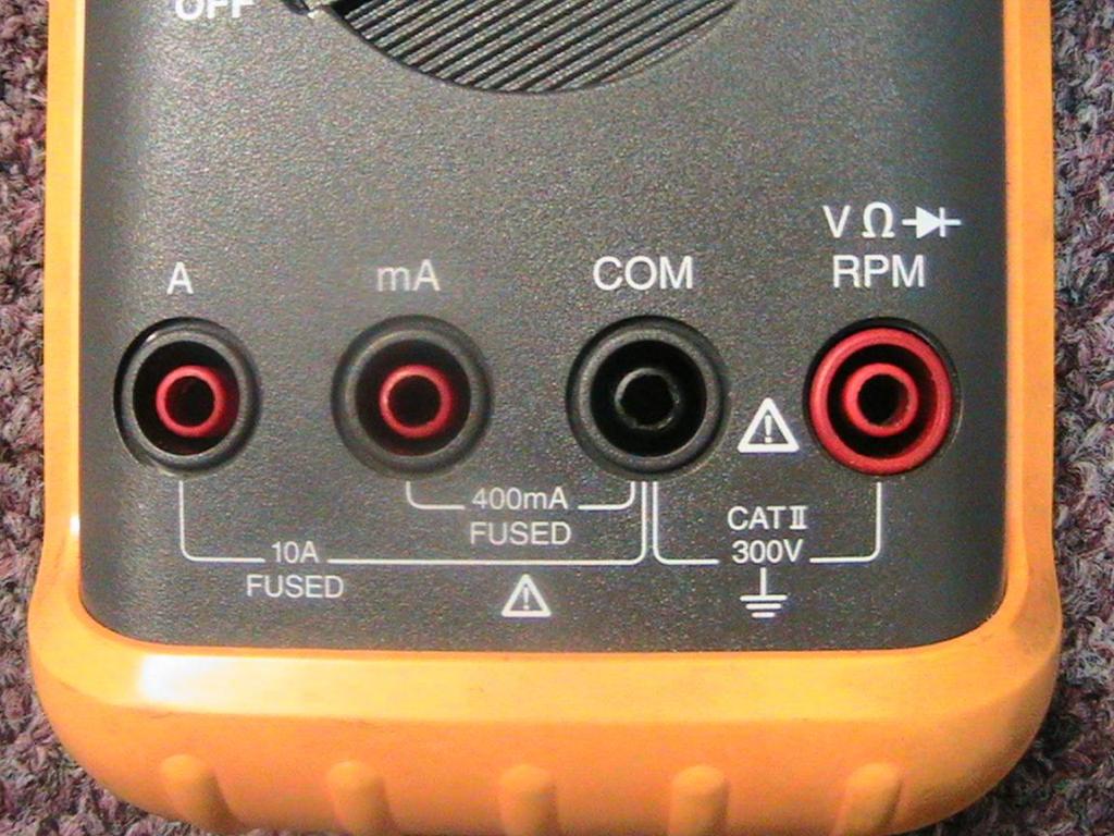
20 6. Besides multi meters, wires, test lights and logic probes are used for diagnosis. Jumper Bumper Thumper

21 7. Non powered 12 volt test lights are used to check for voltage. Drops Available Consumption

22 8. A test light is used to check for continuity. 12 Volt Self Powered 1.5 Volt

23 Logic Probe


24 9. are fast reacting meters that measure & display voltage over time. Lab Rats Lab Tasks Lab Scopes


25 10. A good can do so much more than just read DTC s! Be sure to use the serial data stream, check TSB s, use the pattern failure troubleshooter, and all of the modes. Lead Tech Scan Tool Auto Teacher


26 11. Jumper wires with a or a circuit breaker can be used to by pass wires or switches. Do not use a jumper wire to by pass a consumer or a load. The circuit amps will skyrocket. Fuse Splice Ground


27 12. A computer will preserve power to volatile RAMs when the battery is disconnected for service. Note: The SIR system retains its back up power with a memory saver! Battery Saver Memory Saver RAM/ROM


28 13. A DMM used on computer circuits should have an input of 1 MΩ to 10 MΩ. Resistance Impedance Capacitance


29 14. A DMM used on high voltage hybrid vehicles should be ANSI & SCA 1000 V rated. CAT I CAT II CAT III


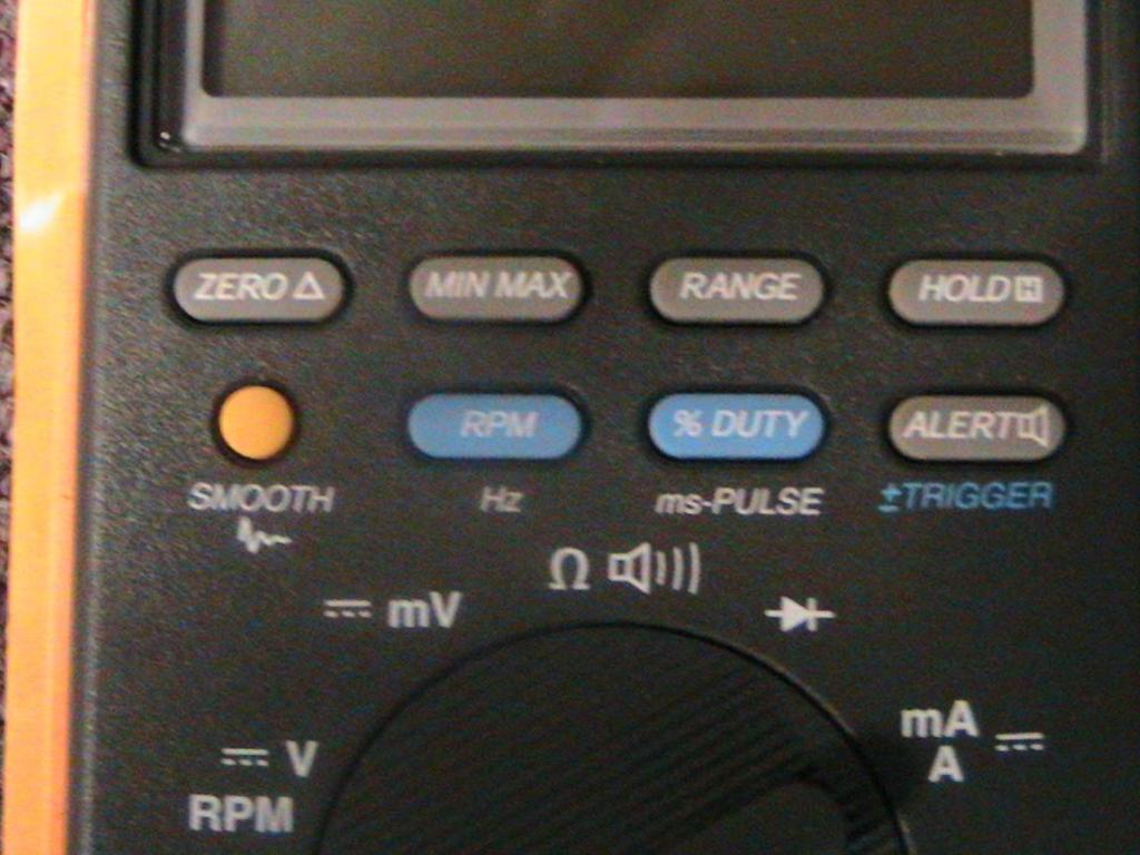
30 15. The auto feature on meters detects the proper range & sets the meter to read it. Ranging MN/MAX Averaging


31 16. A DMM set to measure volts is connected in to a circuit. Series Parallel Inductively
32 12.6 V Source Voltage V Ω A V A OFF V Ω C OM A Current Clamp Carbon Pile
33 17. Voltage tests will find excessive resistance that may not be detected with an ohmmeter. Think of Voltage Drop as Voltage Use by a consumer Drop Available Capacitance
34 0.2 V Voltage Drop V Ω A V OFF A Carbon Pile A V Ω COM Current Clamp


35 18. Ammeters are connected either in series or using pickups to measure current. Inductive Deductive Conductive

36

37 19. Ohmmeters are always used on components disconnected from their source. (open = OL) Voltage Amperage Resistance
38 Remember to Zero your meter before you start measuring!

39 20. The DMM test mode (alert) sounds an audible beep when continuity exists. Continuity Hertz Smooth

40 21. The DMM / is a record function that is useful in capturing intermittent problems. MIN/MAX Pulse Width Smooth
41
42
43

44 22. A DMM may also measure which is a percentage of circuit on time. normally measured in milliseconds, and in hertz. Duty Cycle, Pulse Width, Frequency
45 23. On a lab scope, voltage is shown on the axis. Vertical Horizontal Z

46 24. On a lab scope, time is shown on the axis. Vertical Horizontal Z

47 25. Lab scopes can display momentary electrical noise, disturbances, and signal. Glitches Snitches Sandwiches

48 Note: The sweep of a scope pattern is another name for the time axis.
49 Frequency is a term that describes how often a signal performs a complete cycle.
50 A cycle is a description of the changes that a signal goes through without repeating itself.
51 Frequency is measured in Hertz. Hertz is a measurement of Cycles per Second.


52 26. An scope is a real time scope. A is a Digital Storage Oscilloscope. Analog, Digital
53 27. Using a DSO, a technician can or capture a signal for closer analysis. Freeze Pinpoint Movie

54 Cursors can be used to measure time between 2 points horizontally. Cursors can be used to measure voltage between 2 points vertically.

55 28. A multiple DSO can display more than one waveform at a time for comparison. Base Face Trace

56 B 1, S 1 HO2S B 1, S 2 HO2S

57

58

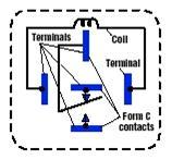
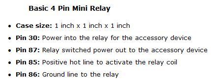
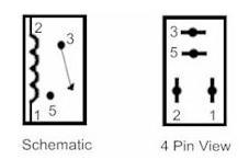
59 29. Waveform amplitude is shown as & waveform frequency is shown as. Voltage, Frequency
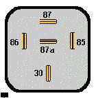
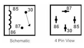
60 30. One complete sine wave is a. One cycle per second is 1 hertz. V O L T A G E TIME Cycle Frequent Repeat


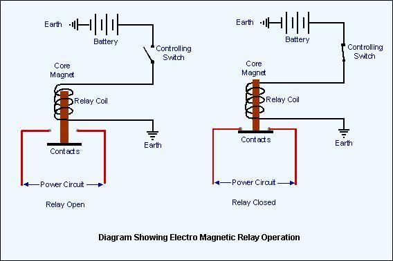
61 31. A is a DMM that displays voltage, resistance, current & frequency as a waveform graph. GMM MMM HMM


62 32. Many DSOs and GMMs allow capture & transfer of screens & data to a PC. True or False
63 33. Measuring across a fuse or other circuit protection device tells more about its condition than a continuity test. Voltage Drop Voltage Available Voltage Capacitance
64


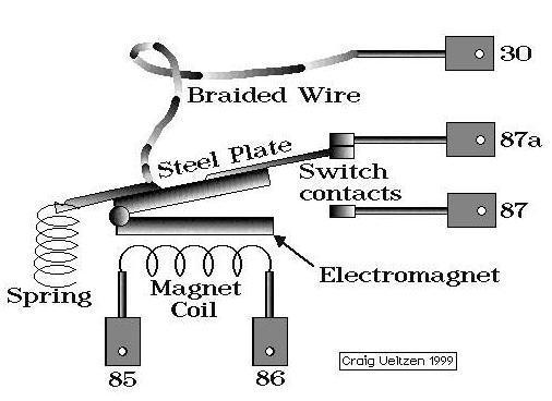
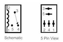
65 34. Some systems, like power seat motors use a PTC as circuit protection. When the current is high, the resistance of the thermistor increases to decrease current or even stop flow. Thermistor Resistor Transistor

66 35. Both manual switches & automatic switches (pressure switch) can be checked, checked for continuity, voltage drop checked or even bypassed with a jumper wire to verify operation. Open Short High Resistance
67 36. Testing of can be done with jumper wires, a volt meter, ohmmeter, or a test light. Relays Relays Relays


68 30 87a a 87
69 A car relay is a electro magnetic switch that uses a small amount of current to control a larger amount of current. How they work is by a wire wound magnetic coil that when excited by a electric current, moves a mechanical spring contact inside the relay, completing a circuit. Car relays are usually controlled by another switch such as your car horn button, headlight switch circuit or power window / door lock switches. Relays are located all over a car, truck, van, suv or hybrid. They are placed in the engine compartment, fuse box or fuse panel, under the dash board or behind door panels and kick panels. Check your owners manual or service manual for exact placement 30 87a 87
70
71
72
73 The control circuit (GREEN) powers the coil inside the relay, using a small amount of current. It flows from the battery, thru the fuse ( for protection) to a switch, (say, a light switch) then to the coil in the relay, energizing it.
74 The coil, now energized becomes an electromagnet, and attracts the metal strip with the contacts, which closes, providing a secondary heavy current path ( RED ) to the device ( say, the fog lights) Turning off the switch, opens the circuit to the coil, removes current flow, and the electromagnet is no longer a magnet, the secondary path is opened, and the lights extinguish. As the relay turns off, the voltage spike (inductive kick) will take place in the coil & may need a clamping diode to protect the control circuit.
75
76
77
78
79 NOTE: In a basic or resistor protection relay, pins 1 and 2 of the micro relays and pins 85 and 86 of the mini relays can be interchanged positive or negative. In a diode protected relay, Mini relays must be pin 85 (+) power, pin 86 ( ) ground / Micro relays must be pin 2 (+) power, pin 1 ( ) ground. Look for a relay diagram or a relay schematic that is printed on the side of the relay to determine.
80 Protection Diode = Clamping Diode, Parallel to Coil for Spike Suppression Current flowing through a relay coil creates a magnetic field which collapses suddenly when the current is turned off. The sudden collapse of the magnetic field induces a brief high voltage across the relay coil that wants to flow in the opposite direction which can cause damage to a ECM, PCM or ICs. A quenching protection diode or suppression resistor allows the induced voltage a path to block and dissipate. This prevents spiked voltage becoming high enough to cause damage to a electronic control module or a IC.
81 Spike Suppression Resistor Located Parallel to Coil Current flowing through a relay coil creates a magnetic field which collapses suddenly when the current is turned off. The sudden collapse of the magnetic field induces a brief high voltage across the relay coil that wants to flow in the opposite direction which can cause damage to a ECM, PCM or ICs. A quenching protection diode or suppression resistor allows the induced voltage a path to block and dissipate. This prevents spiked voltage becoming high enough to cause damage to a electronic control module or a IC.
82
83

84
85


86 37. The best way to test a stepped resistor is with an ohmmeter. True or False


87 38. An unpowered can be sweep tested with an ohmmeter, preferably a GMM. Potentiometer Capacitor Transistor
88


89
90 39. The best way to check wiring is to check the across it. Current Voltage Available Voltage Drop

91 40. When troubleshooting, verify the complaint, then use the wiring diagrams & do quick checks of source & ground to narrow the problem down. Voltage Amperage Resistance


92 41. When probing, using too large of an adapter can deform & loosen terminals. Front Back Side


93 42. probing is necessary when tests like voltage drop need to be done on a live circuit. Front Back Side


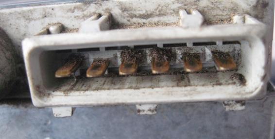
94 43. If you test wiring by through the insulation, cover the damage to prevent corrosion. Piercing Slicing Dicing

95 44. For circuit diagnosis a diagram is one of the most important sources of information. Wiring Vacuum Symptom

96 45. Connectors and are typically numbered to make location easier. (Cxxx Sxxx Gxxx) Grounds Wires Bulbs
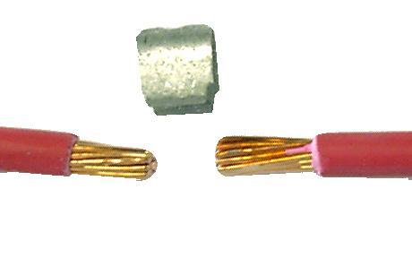
97 46. When tracing a circuit on a schematic, start at the that is not working, find its source, its ground, its switch or control, and the circuit protection. Then get busy with the DMM! This Circuit Has Splices Connectors Grounds Source Component, Consumer, or Load Ground

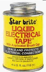
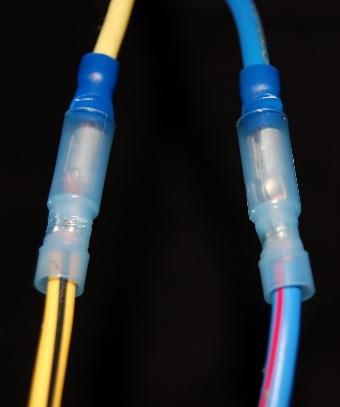
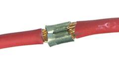
98 47. Printing out the circuit & using to trace it can help avoid confusion. Black Marker Highlighter Lipstick

99 48. All circuit issues can be boiled down to 1 of 3 things:, & high. Opens, Shorts, High Resistances Fuses, Wiring, Consumers Grounds, Splices, Connectors


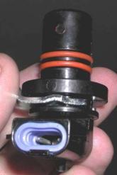
100 49. A component with a shorted coil of wire will read than specs or even zero resistance. Greater Less Same

101 50. A fuse never blows without a reason, probably blown due to a to ground. Open Short High Resistance


")
102 51. High resistance problems are typically caused by that decreases intensity. (amps) Corrosion Solder Electrical Tape

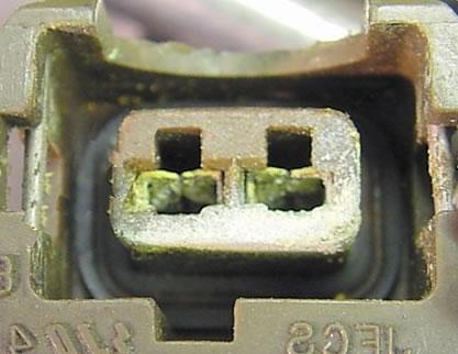
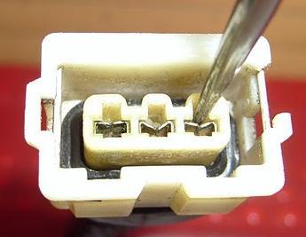
103 52. Many electrical problems can be traced to faulty wiring or. Connections Splices Grounds


104 53. Re routing wires can result in unwanted voltages from electromagnetic fields. Induced Reduced Seduced


105 54. All replacement wires should be the size or larger than the original, never smaller. Same Same Same


106 55. wires (the proper way to connect wires) joins them by melting a lead & tin alloy and allowing it to flow into the joint. 60/40 rosin core solder of a.032 diameter works well. Welding Twisting Soldering


107 56. When soldering near heat sensitive components, use a heat to prevent damage. Shrink Sink Stick


108 57. After crimping & soldering a wire splice, place shrink tubing over the splice, and warm it with a heat gun to protect the joint from elements that could cause corrosion & shorts. Meat Heat Cold


109 58. Wire terminal and release tools prevent connector damage when unlocking terminals. Picks Sticks Tricks
Modern Auto Tech Study Guide Chapter 8 Pages Electricity & Electronics 37 Points. Automotive Service
 Modern Auto Tech Study Guide Chapter 8 Pages 97 110 Electricity & Electronics 37 Points Automotive Service 1. is the movement of electrons ( ) from atom to atom. Every vehicle system uses some type of
Charging Systems. ATASA 5 th. ATASA 5 TH Study Guide Chapter 19 Pages Charging Systems 42 Points. Please Read The Summary
 ATASA 5 TH Study Guide Chapter 19 Pages 571 595 42 Points Please Read The Summary 1. The primary purpose of the charging system is to the battery with a constant and relatively low charge after it has
UNIT 3: GENErAL ELECTriCAL SySTEM DiAGNOSiS
 Electrical/Electronic Systems UNIT 3: GENErAL ELECTriCAL SySTEM DiAGNOSiS LESSON 3: TEST electrical circuits I. Types of electrical circuit tests and electrical faults A. Different types of electrical
Contacts The moveable contact, which is the one affected by the armature is sometimes referred to as the hinge contact.
 Relays & Wiring 101 Basically, a relay is an electrically operated, remotely controlled switch. A simple electromagnetic relay is an adaptation of an electromagnet. It consists of a coil of wire surrounding
Selected excerpts from the book: Lab Scopes: Introductory & Advanced. Steven McAfee
 Selected excerpts from the book: Lab Scopes: Introductory & Advanced Steven McAfee 1. 2. 3. 4. 5. 6. Excerpt from Chapter 1 Lab Scopes How do they work? (page 6) Excerpt from Chapter 3 Pattern Recognition
The Hands On Vehicle Testing Reference
 The Hands On Vehicle Testing Reference A guide for the professional vehicle technician as well as the interested DIY. Over 800 photos and illustrations show "How To" test: batteries, computer/modules and
SECTION 4 ELECTRIC MOTORS UNIT 17: TYPES OF ELECTRIC MOTORS UNIT OBJECTIVES UNIT OBJECTIVES 3/21/2012
 SECTION 4 ELECTRIC MOTORS UNIT 17: TYPES OF ELECTRIC MOTORS UNIT OBJECTIVES After studying this unit, the reader should be able to Describe the different types of open single-phase motors used to drive
STARTING SYSTEMS 8B - 1 STARTING SYSTEMS CONTENTS
 TJ STARTING SYSTEMS 8B - 1 STARTING SYSTEMS CONTENTS page DESCRIPTION AND OPERATION STARTER MOTOR... 2 STARTER RELAY... 3 STARTING SYSTEM... 1 DIAGNOSIS AND TESTING STARTER MOTOR... 8 STARTER MOTOR NOISE
ELECTRICAL. CDTA Technical Training Center
 ELECTRICAL ATOMIC STRUCTURE Protons positive charge Electron negative charge Neutron - neutral Electricity is the movement of electrons from atom to atom ELECTRON FLOW CONDUCTOR - Materials which have
ATASA 5 th. Detailed Diagnosis & Sensors. Please Read The Summary
 ATASA 5 TH Study Guide Chapter 26 Pages 764 809 51 Points Please Read The Summary 1. Many different sensors are involved in the overall driveability of a vehicle. Input Processing Output Electronic Engine
AUTOMOTIVE TECHNOLOGY Electricity and Electronics
 AUTOMOTIVE TECHNOLOGY Electricity and Electronics Al Santini Retired, College of DuPage Glen Ellyn, Illinois Jack Erjavec, Series Editor Professor Emeritus, Columbus State Community College Columbus, Ohio
Electrical Motor Controls Chapter 4 (Fourth Edition) Chapter 2 (Fifth Edition)
 Chapter 2 (Fifth Edition)") Electrical Motor Controls Chapter 4 (Fourth Edition) Chapter 2 (Fifth Edition) 1. Which drawing type shows physical details as seen by the eye? 2. Which drawing is similar to a pictorial drawing but has
Electrical Motor Controls Chapter 4 (Fourth Edition) Chapter 2 (Fifth Edition) 1. Which drawing type shows physical details as seen by the eye? 2. Which drawing is similar to a pictorial drawing but has
WORKSHOP MANUAL ELECTRICITY
 WORKSHOP MANUAL ELECTRICITY GB reference : 754282 DC/ATR 04/2000 1. Electric units:...2 2. Key formulae to remember:...2 3. Definitions:...3 4. Elements:...4 Resistances:...4 Lights:...5 Condensers:...5
Digital Multimeter: This handheld device is used by this course to measure voltage and resistance we will not use this to measure current or capacitan
 Digital Multimeter: This handheld device is used by this course to measure voltage and resistance we will not use this to measure current or capacitance. For current you will use an analog ammeter and
Power Probe IV Users Manual
 Power Probe IV Users Manual The Next Generation of Diagnostics Power Probe IV Page 1 Table of Contents Introduction... 2 Safety... 3 Appearance and Controls... 4-5 Start Up... 6 Mode Navigation... 7 Testing
SECTION 3 BASIC AUTOMATIC CONTROLS UNIT 15 Troubleshooting Basic Controls
 SECTION 3 BASIC AUTOMATIC CONTROLS UNIT 15 Troubleshooting Basic Controls UNIT OBJECTIVES After studying this unit, the reader should be able to Describe and identify power- and non-power-consuming Describe
INDEX Section Page Number Remarks
 INDEX Section Page Number Remarks Synchronous Alternators 2 4 General Fault Finding Capacitors 5 6 Fault Finding & Testing Diodes,Varistors, EMC capacitors & Recifiers 7 10 Fault Finding & Testing Rotors
Electrical Motor Controls (Fourth Edition)
") Electrical Motor Controls (Fourth Edition) 1. Which drawing type shows physical details as seen by the eye? Pictorial Drawing 2. Which drawing is similar to a pictorial drawing but has circles or rectangles
Electrical Motor Controls (Fourth Edition) 1. Which drawing type shows physical details as seen by the eye? Pictorial Drawing 2. Which drawing is similar to a pictorial drawing but has circles or rectangles
Phase 1 Workshop Home Study Guide
 Phase 1 Workshop Home Study Guide Vehicle Electrical-Electronics Troubleshooting Training Written and Developed by Vince Fischelli Director of Training Veejer Enterprises Inc. / Garland, Texas U.S.A. Phone:
Error codes Diagnostic plug Read-out Reset Signal Error codes
 Error codes Diagnostic plug Diagnostic plug: 1 = Datalink LED tester (FEN) 3 = activation error codes (TEN) 4 = positive battery terminal (+B) 5 = ground Read-out -Connect LED tester to positive battery
ATASA 5 th. ATASA 5 TH Study Guide Chapter 28 Pages Ignition Diagnosis & Service 62 Points. Please Read the Summary
 ATASA 5 TH Study Guide Chapter 28 Pages 836 873 62 Points Please Read the Summary Before We Begin Keeping in mind the Career Cluster of Transportation, Distribution & Logistics Ask yourself: What TDL careers
The PCM is the on-board computer which receives input from various sensors and, with this information, controls various engine & emissions control
 The PCM is the on-board computer which receives input from various sensors and, with this information, controls various engine & emissions control actuators. The PCM has various memories within it. These
ATASA 5 th. ATASA 5 TH Study Guide Chapter 31 Pages EFI Diagnosis & Service 47 Points. Please Read The Summary
 ATASA 5 TH Study Guide Chapter 31 Pages 922 948 47 Points Please Read The Summary 1. Troubleshooting EFI systems requires step by step test procedures mostly due to the many interrelated components and
Using Electricity. Summary Notes. 1. From the Wall Socket Household appliances. Earth wire and safety.
 Using Electricity Summary Notes Section Content 1. From the Wall Socket Household appliances. Earth wire and safety. 2. Alternating and Direct Battery and transformer. Current Circuit diagrams. Current
TYPE KF UNDER-FREQUENCY RELAY A. Figure 1: Type KF Relay for 60 Hertz without Case. (Front & Rear View.) Front View Rear View
 Front View Rear View") 41-503.21A TYPE KF Front View Rear View Figure 1: Type KF Relay for 60 Hertz without Case. (Front & Rear View.) 2 TYPE KF 41-503.21A lower pin bearing, which is mounted on the frame, with respect to the
41-503.21A TYPE KF Front View Rear View Figure 1: Type KF Relay for 60 Hertz without Case. (Front & Rear View.) 2 TYPE KF 41-503.21A lower pin bearing, which is mounted on the frame, with respect to the
G - TESTS W/CODES - 2.2L
 G - TESTS W/CODES - 2.2L 1994 Toyota Celica 1994 ENGINE PERFORMANCE Toyota 2.2L Self-Diagnostics Celica INTRODUCTION If no faults were found while performing F - BASIC TESTING, proceed with self-diagnostics.
Building Operator Certification Level I
 Building Operator Certification Level I A Partnership of the CUNY Institute for Urban Systems Building Performance Lab, the CUNY School of Professional Studies, and the New York State Energy Research &
In the first part of this series on
 by Mike Van Dyke In the first part of this series on diagnosing ECUs, we went over some basic visual diagnosis of common failures. In this, the second part of the series, we re going to go over some basic
Starting Systems & Traction Motor Systems. ATASA 5 th. ATASA 5 TH Study Guide Chapter 18 Pages Starting & Traction Motor Systems 62 Points
 ATASA 5 TH Study Guide Chapter 18 Pages 537 570 Starting & Traction Motor Systems 62 Points Please Read The Summary 1. Electric are used to start the engine & in hybrids are used to move the vehicle. Motors
BASIC ELECTRICAL MEASUREMENTS By David Navone
 BASIC ELECTRICAL MEASUREMENTS By David Navone Just about every component designed to operate in an automobile was designed to run on a nominal 12 volts. When this voltage, V, is applied across a resistance,
ELECTRIC FENCE ENERGIZER SERVICE MANUAL MODEL 950 SERVICE MANUAL FOR OLLI 950 FENCE ENERGIZERS
 ELECTRIC FENCE ENERGIZER MODEL 950 SERVICE MANUAL Service Manual for OLLI 950 Page 1/16 Date 20.10.2014 Table of Contents...1 1. IMPORTANT SAFETY INSTRUCTIONS...2 2. SPECIFICATIONS...3 3. CONSTRUCTION...4
Diesel Technology: Electrical and Electronic Systems
 Diesel Technology: Electrical and Electronic Systems Instructional/Task Analysis 2. Composition of atoms Unit 1: Introduction to Diesel Electrical and Electronic Systems 3. Electrical charges in atoms
CHARGING SYSTEM 8C - 1 CHARGING SYSTEM CONTENTS
 ZG CHARGING SYSTEM 8C - 1 CHARGING SYSTEM CONTENTS page GENERAL INFORMATION OVERVIEW... 1 DESCRIPTION AND OPERATION BATTERY TEMPERATURE SENSOR... 2 CHARGING SYSTEM OPERATION... 1 ELECTRONIC VOLTAGE REGULATOR...
GENERAL <ELECTRICAL>
 00E-1 GROUP 00E GENERAL CONTENTS HARNESS CONNECTOR INSPECTION................... 00E-2............. 00E-6................. 00E-6 TROUBLESHOOTING STEPS.......... 00E-6 INFORMATION FOR DIAGNOSIS.......
A/C Generator Systems
 A/C Generator Systems What is the function of the charging system? Provide power for all electrical loads Recharge the starting battery What happens if the charging systems puts out too much power? Voltage
Ch 4 Motor Control Devices
 Ch 4 Motor Control Devices Part 1 Manually Operated Switches 1. List three examples of primary motor control devices. (P 66) Answer: Motor contactor, starter, and controller or anything that control the
Chapter 2. Battery Charger and Base Assembly
 Chapter 2 Battery Charger and Base Assembly 11 CHAPTER 2. BATTERY CHARGER AND BASE ASSEMBLY 2.1 Section Overview This Lab teaches students how to assemble a Tekbot, in the following steps: Describe the
Miniature circuit breaker Application guide
 Miniature circuit breaker Application guide Miniature Miniature circuit circuit breakers breakers Application S200 guide Introduction The circuit breaker plays an important role in providing over-current
WIRING DIAGRAM INFORMATION
 DR WIRING DIAGRAM INFORMATION 8W01-1 WIRING DIAGRAM INFORMATION TABLE OF CONTENTS page WIRING DIAGRAM INFORMATION DESCRIPTION DESCRIPTION - HOW TO USE WIRING DIAGRAMS...1 DESCRIPTION - CIRCUIT INFORMATION.....
Yaskawa Electric America Unit Troubleshooting Manual Section One: Introduction & Checks Without Power GPD 506/P5 and GPD 515/G5 (0.
 Yaskawa Electric America Unit Troubleshooting Manual Section One: Introduction & Checks Without Power GPD 506/P5 and GPD 515/G5 (0.4 ~ 160kW) Page 1 Introduction This manual is divided into three sections:
2.0 CONSTRUCTION 3.0 OPERATION. SA-1 Generator Differential Relay - Class 1E 2.5 TRIP CIRCUIT
 41-348.11C SA-1 Generator Differential Relay - Class 1E 2.0 CONSTRUCTION The type SA-1 relay consists of: Restraint Circuit Sensing Circuit Trip Circuit Surge Protection Circuit Operating Circuit Amplifier
4.0L CEC SYSTEM Jeep Cherokee DESCRIPTION OPERATION FUEL CONTROL DATA SENSORS & SWITCHES
 4.0L CEC SYSTEM 1988 Jeep Cherokee 1988 COMPUTERIZED ENGINE Controls ENGINE CONTROL SYSTEM JEEP 4.0L MPFI 6-CYLINDER Cherokee, Comanche & Wagoneer DESCRIPTION The 4.0L engine control system controls engine
SL Series Application Notes. SL Series - Application Notes. General Application Notes. Wire Gage & Distance to Load
 Transportation Products SL Series - Application Notes General Application Notes vin 2 ft. 14 AWG The SL family of power converters, designed as military grade standalone power converters, can also be used
C capacitance, 91 capacitors, codes for, 283 coupling, polarized and nonpolarized,
 Index Numbers and Symbols 555 timer, 164 166 making sound using, setting output speed of, 166 167 using for reaction game speed, 260 261 μf (microfarad), 92 Ω (ohms), 7, 70 A A (amperes), 7 AC (alternating
ALTERNATOR PRECAUTIONS. Some precautions should be taken when working on this, or any other, AC charging system.
 The alternator charging system is a negative (-) ground system which consists of an alternator, a regulator, a charge indicator, a storage battery and wiring connecting the components, and fuse link wire.
Service Bulletin Trucks
 Volvo Trucks North America, Inc. Greensboro, NC USA Service Bulletin Trucks Date Group No. Page 9.2003 300 004 1(10) General Safety Practices Electrical and Electronics VN, VHD General Safety Practices
GENERAL <ELECTRICAL>
 00E-1 GROUP 00E GENERAL CONTENTS HARNESS CONNECTOR INSPECTION................................. 00E-2............. 00E-6................. 00E-6 TROUBLESHOOTING STEPS.......... 00E-6 INFORMATION
User Manual. T6 Tachometer. Online: Telephone: P.O. Box St. Petersburg, Florida 33736
 User Manual T6 Tachometer Online: www.phareselectronics.com Telephone: 727-623-0894 P.O. Box 67251 St. Petersburg, Florida 33736 Table of Contents Overview... 1 Description... 1 Wiring... 1 T6 Tachometer
ALTERNATOR - CHRYSLER 40/90-AMP & 50/120 AMP
 ALTERNATOR - CHRYSLER 40/90-AMP & 50/120 AMP 1988 Chrysler LeBaron Convert/Coupe 1988 ELECTRICAL Chrysler Motors 40/90 & 50/120 Amp Alternators FWD Models DESCRIPTION The charging system consists of an
TL RELAYS. TYPICAL APPLICATIONS Head lamp, Fog lamp, Fan motor, etc. ORDERING INFORMATION TYPES. High Load Relay for Smart Junction Box ACTL.
 High Load Relay for Smart Junction Box TL RELAYS High heat-resistant type: Sealed Pin in Paste compliant type: Flux tight New 14.4.7 11.433 1.3 FEATURES Large capacity switching
Handout Activity: HA773
 Charging system HA773-2 Handout Activity: HA773 Charging system The charging system allows for a means to recharge the battery and allow for electrical usage of components in the vehicle. The charging
2002 Buick Rendezvous - AWD
 2002 Buick Rendezvous - AWD DTC P0410 Description The control module activates the secondary air injection (AIR) system by grounding both the pump relay and the vacuum control solenoid control circuits.
Handyman Motor Capacitor Meter PART NO
 Handyman Motor Capacitor Meter PART NO. 2225174 To test a motor-run capacitor in the field with no capacitance meter at hand, you had to hook up the capacitor through an extension cable to a 120V wall
XENON POWER SUPPLY for 10 kw Britelight Lamphead
 XENON POWER SUPPLY for 10 kw Britelight Lamphead Rev. June 2004 STRONG INTERNATIONAL a division of Ballantyne of Omaha, Inc. 4350 McKinley Street Omaha, Nebraska 68112 USA Tel 402/453-4444 Fax 402/453-7238
ELECTRICITY AND HWH COPPER CONDUCTOR
 1. PREFACE +BATTERY TERMINAL +BATTERY TERMINAL + + + + + + + + + + + + ELECTRICITY AND HWH In the first section of this school, we did an in-depth study of general hydraulics. In section four, we applied
Page 1 of 1 ALTERNATORS. Overview. Intek TM V-Twin Cylinder OHV Engine Service Manual Version 1.0. Copyright 1999 by Briggs and Stratton Corporation
 Overview Alternator Identification Page 1 of 3 The alternator systems installed on Briggs & Stratton Intek V-Twin Cylinder OHV Engines can easily be identified by the color of the stator output wires and
Full file at
 CHAPTER 2 FUNDAMENTALS OF ELECTRICITY Job Assignment for This Chapter: You are on a service call and a customer does not understand the basic theory of electricity and thinks you are trying to sell parts
SUPPLEMENTAL RESTRAINT SYSTEM(SRS)
") 52B-1 GROUP 52B SUPPLEMENTAL RESTRAINT SYSTEM(SRS) CONTENTS GENERAL INFORMATION........ 52B-3 SERVICE PRECAUTIONS......... 52B-15 SRS AIR BAG DIAGNOSIS........ 52B-17 INTRODUCTION.....................
52B-1 GROUP 52B SUPPLEMENTAL RESTRAINT SYSTEM(SRS) CONTENTS GENERAL INFORMATION........ 52B-3 SERVICE PRECAUTIONS......... 52B-15 SRS AIR BAG DIAGNOSIS........ 52B-17 INTRODUCTION.....................
ELECTRONICS & HWH 19APR11
 ELECTRONICS & HWH 19APR11 1. PREFACE This section deals with electronic equipment and components. We will discuss common electronic components and components that are specific to HWH. The discussion will
Basic Electricity. Mike Koch Lead Mentor Muncie Delaware Robotics Team 1720 PhyXTGears. and Electronics. for FRC
 Basic Electricity and Electronics for FRC Mike Koch Lead Mentor Muncie Delaware Robotics Team 1720 PhyXTGears The Quick Tour The Analog World Basic Electricity The Digital World Digital Logic The Rest
Beware of Ghost Voltage
 Beware of Ghost Voltage This article serves two purposes. First, it is an article for technicians who have heard of the dreaded ghost voltage but never understood why it happens. Second, for my own apprentices
F - BASIC TESTING Nissan 240SX INTRODUCTION VISUAL INSPECTION COMPRESSION CHECK EXHAUST SYSTEM BACKPRESSURE CHECK
 F - BASIC TESTING 1990 Nissan 240SX 1990 ENGINE PERFORMANCE Nissan - Basic Diagnostic Procedures Nissan; Axxess, Maxima, Pathfinder, Pickup, Pulsar NX, Sentra, Stanza, Van, 240SX, 300ZX INTRODUCTION The
Reproduction or other use of this Manual, without the express written consent of Vulcan, is prohibited.
 SERVICE MANUAL ELECTRIC BRAISING PANS (30 & 40 GALLON) VE30 VE40 ML-126849 ML-126850 VE40 SHOWN - NOTICE - This Manual is prepared for the use of trained Vulcan Service Technicians and should not be used
Advanced Automotive Electricity and Electronics
 MASTER AUTOMOTIVE TECHNICIAN SERIES SAMPE CHAPTER 6 Advanced Automotive Electricity and Electronics We support ASE program certification through Michael Klyde Kirk VanGelder Want to see more? Instructors
National 4 Physics - Electricity and Energy Summary Notes
 Electromagnetism Magnetic fields Magnetic fields are found around any permanent or electromagnet. They are normally invisible but can be shown up by placing a sheet of paper over the magnet and sprinkling
DO NOT REMOVE. Resource Guide. Electrical Systems. Training Center Copy ELTC9916A I N F I N I T I. Revised: January, 2012 START STOP ELTC9916A.
 NISSAN ELTC9916A Resource Guide LOCK Acc ON START STOP ENGINE Advanced Automotive Electrical Systems 14v 100% DO NOT REMOVE Training Center Copy ELTC9916A Revised: January, 2012 I N F I N I T I CREATED
ATASA 5 th. ATASA 5 TH Study Guide Chapter 27 Pages Ignition Systems 68 Points. Please Read the Summary
 ATASA 5 TH Study Guide Chapter 27 Pages 810 835 68 Points Please Read the Summary Before We Begin Keeping in mind the Career Cluster of Transportation, Distribution & Logistics Ask yourself: What careers
Automotive Parts. Charging & Starting Systems
 Automotive Parts Charging & Starting Systems Charging Systems Output voltage kept to about 2 volts higher than battery voltage Controlled by varying current into rotor field winding (voltage regulator
EXTERIOR LAMPS - OPERATION
 2013 Dodge or Ram Truck Journey FWD L4-2.4L Vehicle > Lighting and Horns > Description and Operation > Components EXTERIOR LAMPS - OPERATION OPERATION Following are paragraphs that briefly describe the
Horns, Wiper, and Washer System Operation
 14 Horns, Wiper, and Washer System Operation LEARNING OBJECTIVES Upon completion and review of this chapter, you should be able to: Explain the operation of an automotive horn. Identify the different types
SALDET SALES & SERVICE, INC. CLINTON TOWNSHIP, MICHIGAN
 Form 1254 BRAKETRON Electronic Motor Brake Instructions SALDET SALES & SERVICE, INC. CLINTON TOWNSHIP, MICHIGAN TABLE OF CONTENTS SECTION TITLE PAGE I. Introduction 1 II. Specifications 1 III. Principles
Electronics Technology and Robotics I Week 2 Basic Electrical Meters and Ohm s Law
 Electronics Technology and Robotics I Week 2 Basic Electrical Meters and Ohm s Law Administration: o Prayer o Bible Verse o Turn in quiz Meters: o Terms and Definitions: Analog vs. Digital Displays: Analog
2002 ENGINE PERFORMANCE. Self-Diagnostics - RAV4. Before performing testing procedures, check for any related Technical Service Bulletins (TSBs).
.") 2002 ENGINE PERFORMANCE Self-Diagnostics - RAV4 INTRODUCTION NOTE: Before performing testing procedures, check for any related Technical Service Bulletins (TSBs). To properly diagnosis and repair this
2002 ENGINE PERFORMANCE Self-Diagnostics - RAV4 INTRODUCTION NOTE: Before performing testing procedures, check for any related Technical Service Bulletins (TSBs). To properly diagnosis and repair this
This appendix gives you a general introduction to what electricity is
 C5865_App B_CTP.qxd 24/09/2006 01:50 PM Page 1215 APPENDIX B Electricity and Multimeters This appendix gives you a general introduction to what electricity is and how it is measured. In addition, you will
The Physics of the Automotive Ignition System
 I. Introduction This laboratory exercise explores the physics of automotive ignition systems used on vehicles for about half a century until the 1980 s, and introduces more modern transistorized systems.
Charging System. Activity 11. Battery Drain Testing
 Charging System 812FJ Student Manual Charging System Activity 11 Battery Drain Testing Performance Objectives: Test for and measure battery drain using manufacturer s service procedures. Diagnose the cause
ALTERNATOR - BOSCH 35/75-AMP & 40/90-AMP
 ALTERNATOR - BOSCH 35/75-AMP & 40/90-AMP 1988 Chrysler LeBaron Convert/Coupe 1988 ALTERNATORS & REGULATORS Chrysler Motors - Bosch 35/75 & 40/90 Amp Alternator All Models DESCRIPTION The charging system
Table No. 1 provides a means of identifying the various alternator systems. Note: All output figures are rated at 3600 RPM. TABLE NO.
 The alternator systems installed on Briggs & Stratton Intek OHV-Twin Cylinder Engines can easily be identified by the color of the stator output wires and the connector. Table No. 1 provides a means of
Froggy. We began our dissection of the Mazda. Mazda Retractable Headlights: Part Two
 Froggy came a-shortin azda Retractable Headlights: Part Two We began our dissection of the azda iata retractable headlight system in Part One (April 2001 Import Service). The first article covered the
ANTI-LOCK BRAKE SYSTEM
 ANTI-LOCK BRAKE SYSTEM 1993 Mitsubishi Diamante 1993 BRAKES Mitsubishi - Anti-Lock Brake System Diamante DESCRIPTION The Anti-Lock BRAKE SYSTEM (ABS) is designed to prevent wheel lock-up during heavy braking.
Electronic Dynamo Regulator INSTRUCTION MANUAL. COPYRIGHT 2014 CLOVER SYSTEMS All Rights Reserved
 DRM TM DRM-HP TM Electronic Dynamo Regulator INSTRUCTION MANUAL COPYRIGHT 2014 CLOVER SYSTEMS All Rights Reserved INTRODUCTION The Clover Systems DRM is a state-of-the art all-electronic voltage and current
Fuel Metering System Component Description
 1999 Chevrolet/Geo Tahoe - 4WD Fuel Metering System Component Description Purpose The function of the fuel metering system is to deliver the correct amount of fuel to the engine under all operating conditions.
4 Electricity and Magnetism
 4 Electricity and Magnetism 1. Simple phenomena of magnetism 2. Electrical quantities 3. Electrical circuits 4. Dangers of electricity 5. Electromagnetic effects 6. Cathode ray oscilloscope 1. The diagram
TEST SPECIFICATIONS AND TASK LIST ELECTRICAL/ELECTRONIC SYSTEMS (TEST A6)
") TEST SPECIFICATIONS AND TASK LIST ELECTRICAL/ELECTRONIC SYSTEMS (TEST A6) Content Questions Percentage Area in Test of Test A. General Electrical/Electronic System 13 26% Diagnosis B. Battery Diagnosis
TEST SPECIFICATIONS AND TASK LIST ELECTRICAL/ELECTRONIC SYSTEMS (TEST A6) Content Questions Percentage Area in Test of Test A. General Electrical/Electronic System 13 26% Diagnosis B. Battery Diagnosis
Installing Ignition Coil relay
 Installing Ignition Coil relay Above is a schematic diagram of the coil relay modification. All it really does is, it uses the existing 12 Volt positive that normally powers the coils, to power a relay,
Maxi and Mini DC-DC Converter Evaluation Board
 BRICK FAMILY USER GUIDE Maxi and Mini DC-DC Converter Evaluation Board Features...1 Introduction...2 Set Up + OUT, OUT...3 + S, S...3 Secondary Control (SC)...3 Primary Control (PC)...4 Parallel (PR)...4
Chapter 3. ECE Tools and Concepts
 Chapter 3 ECE Tools and Concepts 31 CHAPTER 3. ECE TOOLS AND CONCEPTS 3.1 Section Overview This section has four exercises. Each exercise uses a prototyping board for building the circuits. Understanding
Understanding The HA2500's Horiz Driver Test
 Understanding The HA2500's Horiz Driver Test Horizontal output stage symptoms and component failures are often caused by problems in the horizontal driver stage. The horizontal driver stage is seldom suspected,
Electrical Energy and Power Ratings
 Section 1 - From the Wall Socket Electrical Energy and ower Ratings Batteries and the mains are sources of electrical energy. Electrical appliances can then convert this into other forms of energy. e.g.
3. OPERATION 2.1. RESTRAINT CIRCUIT 2.6. INDICATING CIRCUIT 2.2. OPERATING CIRCUIT 2.7. SURGE PROTECTION CIRCUIT 2.3.
 41-348.1H Type SA-1 2.1. RESTRAINT CIRCUIT The restraint circuit of each phase consists of a center-tapped transformer, a resistor, and a full wave rectifier bridge. The outputs of all the rectifiers are
USING A DIGITAL STORAGE OSCILLOSCOPE IN 2016
 4210 rue Jean-Marchand, Quebec, QC G2C 1Y6, Canada Phone: 418 688 9067 / 800 567 0791 / 810 222 4525 (USA) Fax: 418 843 3444 / Email: info@ A ConsuLab presentation USING A DIGITAL STORAGE OSCILLOSCOPE
CHAPTER 2. Current and Voltage
 CHAPTER 2 Current and Voltage The primary objective of this laboratory exercise is to familiarize the reader with two common laboratory instruments that will be used throughout the rest of this text. In
Electric Motor Controls BOMA Pre-Quiz
 Electric Motor Controls BOMA Pre-Quiz Name: 1. How does a U.P.S. (uninterruptable power supply) work? A. AC rectified to DC batteries then inverted to AC B. Batteries generate DC power C. Generator, batteries,
Farr High School NATIONAL 4 PHYSICS. Unit 1 Electricity and Energy. Revision Notes
 Farr High School NATIONAL 4 PHYSICS Unit 1 Electricity and Energy Revision Notes Content Practical electrical and electronic circuits - Measurement of current, voltage and resistance using appropriate
Using your Digital Multimeter
 Using your Digital Multimeter The multimeter is a precision instrument and must be used correctly. The rotary switch should not be turned unnecessarily. To measure Volts, Milliamps or resistance, the black
Current Electricity. 3 rd Years
 Current Electricity 3 rd Years Comparing: Flow of electricity to flow of water. Electric Current An electric current is a flow of electric charge. An electric current is caused by the flow of electrons
C.E. Niehoff & Co. C653/C653A and C625 Alternators Troubleshooting Guide NOTICE. Hazard Definitions. Battery Charge Volt and Amp Values
 C.E. Niehoff & Co. C653/C653A and C625 Alternators Troubleshooting Guide Hazard Definitions These terms are used to bring attention to presence of hazards of various risk levels or to important information
with lcd display 12-42v
 instructions for: AUTO PROBE with lcd display 12-42v MODEL No: PP7 Thank you for purchasing a Sealey product. Manufactured to a high standard this product will, if used according to these instructions
SPN 3232 or Suspect Parameter Number (SPN) and Failure Mode Indicator (FMI) Description
 and Failure Mode Indicator (FMI) Description") SPN 3232 or 3271 Suspect Parameter Number (SPN) and Failure Mode Indicator (FMI) Description SPN FMI Description Possible Causes 3232 5 EGO Bank A Post Cat Heater Malfunctioning heater relay. Circuit Open/Shorted
SPN 3232 or 3271 Suspect Parameter Number (SPN) and Failure Mode Indicator (FMI) Description SPN FMI Description Possible Causes 3232 5 EGO Bank A Post Cat Heater Malfunctioning heater relay. Circuit Open/Shorted
Chapter 9 Basic meters
 Chapter 9 Basic meters Core Competency Units UEENEEE003B Solve problems in extra-low voltage single path circuits UEENEEE004B Solve problems in multiple path DC Circuits Essential Knowledge and Associated