A/C Generator Systems
|
|
|
- John Floyd
- 6 years ago
- Views:
Transcription
1 A/C Generator Systems
2 What is the function of the charging system? Provide power for all electrical loads Recharge the starting battery
3 What happens if the charging systems puts out too much power? Voltage goes UP What happens if the charging system puts out too little power? Voltage goes DOWN
4 What is the proper system voltage? volts What controls the system voltage? Voltage regulator
5 How many volts in a fully charged 12.6 volts battery? After removing surface charge
6 How do you check for an Over charging alternator? Insure battery is fully charged Run the engine Turn Off electrical loads System voltage below 14.8 Volts When less than 8 amps enter battery
7 What can cause the charging system to Over charge? Defective Voltage Regulator Volt Drop in Voltage Sensing Wire Volt Drop in regulator ground Having regulator inside generator eliminates volt drop as a cause for Over Charging
8 How do you check for an undercharging alternator? Insure battery is fully charged Run ALL electrical loads Run engine at 2,000 RPM System voltage above 13.8 Volts
9 What can cause the charging system to Loose fan belt under charge? Low engine RPM Excessive load requirements (add on accessories)
10 What can cause the charging system to under charge? Short driving trips Defective generator Defective voltage regulator Defective wiring
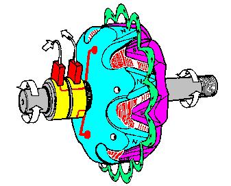
11 Understand the A/C Generator (Alternator) Identify the following components Rotor Stator Slip rings Brushes Diodes or Rectifier

12 Rotor, creates spinning magnetic field

13 Stator, creates alternating current

14 Slip Rings, allow field current into the rotor

15 Brushes, allow field current into rotor
16 Rotor (Field) What does the Rotor do? Creates a spinning magnetic field inside the A/C generator
17
18
19 Stator Windings What does the Stator do? Creates electrical power when a magnetic field is moved past it Creates power to recharge battery and run electrical loads
20 What does the Stator do? Creates an Alternating Current
21
22
23
24
25 How does the A/C current change into D/C current Diodes are used for Full Wave Rectification Diodes are often called rectifiers
26
27
28 A/C D/C Full Wave Rectification... one stator winding
29 A/C D/C Full Wave Rectification... one stator winding
30 A/C D/C Full Wave Rectification... one stator winding
31 Full Wave Rectification... three stator windings
32 Actual voltage trace of each stator winding after full wave rectification
33 voltage trace on oscilloscope (diode pattern)

34 Stator Rectifier (Diode pack)

35 Positive Diode Heat-sink Negative Diode Heat-sink B+ Main Charge Terminal Stator Wires Voltage Regulator
36 Rotor (Field) Negative Diodes B+ Positive Diodes Stator windings
37 Test the electrical integrity of the diodes
38 Here is a fairly normal diode pattern
39 Here is a fairly normal diode pattern
40 Open diode pattern
41 Shorted diode pattern
42 Practice and it gets easy to spot defective diode patterns! Scope set for A/C voltage
43 Practice with Diode Patterns Different alternator diodes give slightly different diode patterns If you look at many different alternator diode patterns you will learn to quickly spot bad diodes Defective diodes can cause many engine performance problems
44 How can you increase the amperage coming out of the generator? Increase engine RPM (This is limited to about 2500 RPM) Increase the rotor s magnetic field strength (This is the job of the voltage regulator) Use a Delta stator winding
45
46 How does the voltage regulator control the A/C generator? The regulator will turn on/off current to the field windings (rotor) Increasing current to the rotor will increase generator output
47 How does the voltage regulator control the A/C generator? Regulators are wired to the Ground side of the Rotor in an A type circuit and wired to the Battery side of the Rotor in a B type circuit
48 A circuit regulator More power (ON)
49 A circuit regulator Less power (OFF)
50 B circuit regulator More power (ON)
51 B circuit regulator Less power (OFF)
52 Voltage regulators monitor Voltage ( normal range) Temperature Colder = higher charge voltage (May look like an overcharge when very cold) Warmer = lower charge voltage (May look like an undercharge when generator heats up!)
53 Advantages to computer voltage regulation PCM can more closely regulate system voltage PCM can raise idle RPM for higher electrical loads Reduced alternator drag on engine (fuel economy) when charging is not critical Diagnostic Trouble Codes (DTC s) for charging system PCM may ground or unground the Field (ROTOR) PCM may control integral regulator (inside generator)
54 Charge Indicator Lamp Most charge indicator lamps ground when the alternator output stops. Some systems feed the field (rotor) through the charge lamp. Always check this lamp to light when Key is ON and Engine is OFF

55 Charge Indicator Lamp When generator begins to charge, the charge indicator lamp will have positive voltage applied to BOTH sides of the bulb. This will remove the ground and turn off the lamp
56 Explain how charging system indicators work Idiot light (Charge Indictor) Lamp will light with key ON engine OFF and goes out when ground is lost. Voltmeter Simple to wire any power and ground to voltmeter in dash. Very inaccurate. Usually used with a Charge Indictor Lamp Ammeter
57 Ammeter Set up to read amps charging battery only. Should show charge immediately after starting engine
58 Diagnose Over/Under Charging Insure there is no Voltage drop in wiring harness Undercharge is bad alternator or regulator Overcharge is bad regulator IF there are no bad wires or connections
59 Field is ON Alternator charging
60 Field is OFF Alternator not charging
61 Voltage too high causing Overcharge Field is ON Alternator charging Overcharge caused by volt drop in wires
62 Voltage too high causing Overcharge Overcharge caused by volt drop in ground Regulator sees drops 14.5 V 14.9 V to 0.4V Field is ON Alternator charging
63 Regulator sees alternator voltage Volt Drop in battery cables will cause undercharging Field is OFF Alternator not charging
64 Test the Charging System Test belts, battery condition and wiring to ensure trouble free power Test for Overcharging (with full charge on battery) Test for Undercharging Test for A/C voltage
65 Alternator Testing the Bottom Line Complete records (work order) and protect vehicle Battery condition is critical (load test) Battery must be fully charged to test the voltage regulator Check Drive Belt and Wiring Harness Check Cranking Voltage and Starter Amp Draw Check for Maximum Alternator Output (watching Volts or Amps) Test Voltage Regulator & Volt Drop to Alternator Check the Diodes A/C volts and ripple pattern Perform a Parasitic Draw Test
66 Can you do this? Insuring the starting and charging systems work reliably is a critical skill for an electrical technician You will demonstrate your competence at testing Batteries, Starting systems and Charging systems This will count as part of your final test score Testing will be during the last two weeks of class
CHARGING SYSTEM 8C - 1 CHARGING SYSTEM CONTENTS
 TJ CHARGING SYSTEM 8C - 1 CHARGING SYSTEM CONTENTS page DESCRIPTION AND OPERATION BATTERY TEMPERATURE SENSOR... 2 CHARGING SYSTEM OPERATION... 1 ELECTRONIC VOLTAGE REGULATOR... 2 GENERATOR... 1 DIAGNOSIS
AUT 125 ELECTRICAL II CH 54 & 55 CHARGING SYSTEMS
 Name: Class: Date: AUT 125 ELECTRICAL II CH 54 & 55 CHARGING SYSTEMS Multiple Choice Identify the choice that best completes the statement or answers the question. 1. Technician A says that the diodes
CHARGING SYSTEM 8C - 1 CHARGING SYSTEM CONTENTS
 ZG CHARGING SYSTEM 8C - 1 CHARGING SYSTEM CONTENTS page GENERAL INFORMATION OVERVIEW... 1 DESCRIPTION AND OPERATION BATTERY TEMPERATURE SENSOR... 2 CHARGING SYSTEM OPERATION... 1 ELECTRONIC VOLTAGE REGULATOR...
Charging Systems. ATASA 5 th. ATASA 5 TH Study Guide Chapter 19 Pages Charging Systems 42 Points. Please Read The Summary
 ATASA 5 TH Study Guide Chapter 19 Pages 571 595 42 Points Please Read The Summary 1. The primary purpose of the charging system is to the battery with a constant and relatively low charge after it has
Just what is an alternator?
 Just what is an alternator? An alternator is the device used to produce the electricity the car needs to run and to keep the battery charged. The battery is the heart of your electrical system. But you
Battery Operation. Battery Construction. Battery State Of Charge. Battery Load Test. Battery Rating Systems 2/14/12
 Battery Operation Batteries, Charging and Donald Jones Brookhaven College Batteries convert chemical energy into electrical energy During discharge the battery s plate composition is changed During charging
ALTERNATOR - CHRYSLER 40/90-AMP & 50/120 AMP
 ALTERNATOR - CHRYSLER 40/90-AMP & 50/120 AMP 1988 Chrysler LeBaron Convert/Coupe 1988 ELECTRICAL Chrysler Motors 40/90 & 50/120 Amp Alternators FWD Models DESCRIPTION The charging system consists of an
ALTERNATOR - BOSCH 35/75-AMP & 40/90-AMP
 ALTERNATOR - BOSCH 35/75-AMP & 40/90-AMP 1988 Chrysler LeBaron Convert/Coupe 1988 ALTERNATORS & REGULATORS Chrysler Motors - Bosch 35/75 & 40/90 Amp Alternator All Models DESCRIPTION The charging system
Handout Activity: HA773
 Charging system HA773-2 Handout Activity: HA773 Charging system The charging system allows for a means to recharge the battery and allow for electrical usage of components in the vehicle. The charging
C.E. Niehoff & Co. C653/C653A and C625 Alternators Troubleshooting Guide NOTICE. Hazard Definitions. Battery Charge Volt and Amp Values
 C.E. Niehoff & Co. C653/C653A and C625 Alternators Troubleshooting Guide Hazard Definitions These terms are used to bring attention to presence of hazards of various risk levels or to important information
STARTER CIRCUIT TROUBLESHOOTING
 2000 Honda Accord EX Sedan V6-3.0L Vehicle > Starting and Charging > Starting System > Starter Motor > Testing and Inspection > Component Tests and General Diagnostics STARTER CIRCUIT TROUBLESHOOTING Starter
1984 Jeep CJ7. IGNITION SYSTEM - SOLID STATE' 'Distributors & Ignition Systems MOTORCRAFT SOLID STATE IGNITION (SSI)
") TESTING SECONDARY CIRCUIT CHECK CAUTION: When checking secondary voltage, do not remove spark plug wires from spark plugs No. 3 on 4-cylinder, No. 1 or 5 on 6-cylinder and No. 3 or 4 on V8 Engines. 1.
TESTING SECONDARY CIRCUIT CHECK CAUTION: When checking secondary voltage, do not remove spark plug wires from spark plugs No. 3 on 4-cylinder, No. 1 or 5 on 6-cylinder and No. 3 or 4 on V8 Engines. 1.
SECTION 1E ENGINE ELECTRICAL
 SECTION 1E ENGINE ELECTRICAL CAUTION: Disconnect the negative battery cable before removing or installing any electrical unit or when a tool or equipment could easily come in contact with exposed electrical
600 Series Troubleshooting Guide for C651 and C654 Alternators
 600 Series Troubleshooting Guide for C651 and C654 Alternators Hazard Definitions These terms are used to bring attention to presence of hazards of various risk levels or to important information concerning
N1233 Series Troubleshooting Guide for N Alternator
 N1233 Series Troubleshooting Guide for N1233-2 Alternator Hazard Definitions These terms are used to bring attention to presence of hazards of various risk levels or to important information concerning
C627, C628, C631, C656, C657, C658, C671 and C680 Alternator Troubleshooting Guide
 C627, C628, C631, C656, C657, C658, C671 and C680 Alternator Troubleshooting Guide Hazard Definitions These terms are used to bring attention to presence of hazards of various risk levels or to important
Troubleshooting Guide for N1225-1/N1237-1/N Alternators
 Troubleshooting Guide for N1225-1/N1237-1/N1505-1 Alternators Hazard Definitions These terms are used to bring attention to presence of hazards of various risk levels or to important information concerning
10.0 Alternator Test
 10.0 Alternator Test An alternator is the device used to produce the electricity the car needs to run and to keep the battery charged. The alternator uses the principle of electromagnetic induction to
N1240/N1243 Series Troubleshooting Guide for N1240-3/N Alternators
 N1240/N1243 Series Troubleshooting Guide for N1240-3/N1243-2 Alternators Hazard Definitions These terms are used to bring attention to presence of hazards of various risk levels or to important information
Electrical Systems. Introduction
 Electrical Systems Figure 1. Major Components of the Car s Electrical System Introduction Electricity is used in nearly all systems of the automobile (Figure 1). It is much easier to understand what electricity
C802/C802D/C802TD/C820 Alternators Troubleshooting Guide
 C802/C802D/C802TD/C820 Alternators Troubleshooting Guide Hazard Definitions These terms are used to bring attention to presence of hazards of various risk levels or to important information concerning
C.E. Niehoff & Co. N1601, N1602, N1603, and N1604 Alternator Troubleshooting Guide NOTICE. Hazard Definitions. Battery Charge Volt and Amp Values
 C.E. Niehoff & Co. N1601, N1602, N1603, and N1604 Alternator Troubleshooting Guide Hazard Definitions These terms are used to bring attention to presence of hazard(s) of various risk levels or to important
1. SPECIFICATION
 000000 093 1. SPECIFICATION Specification HPS EPS Alternator Crankshaft pulley : Alternator Pulley 1 : 2.94 Normal output (idling/2200 rpm) 70/120 A 70/140A Regulator voltage 14.6 V Brush Length 12.5 mm
Unit AE01K Knowledge of Locating and Correcting Simple Electrical Faults in the Automotive Workplace
 Assessment Requirements Unit AE01K Knowledge of Locating and Correcting Simple Electrical Faults in the Automotive Workplace Content: Basic electrical principles a. Explain the direction of current flow
ALTERNATOR PRECAUTIONS. Some precautions should be taken when working on this, or any other, AC charging system.
 The alternator charging system is a negative (-) ground system which consists of an alternator, a regulator, a charge indicator, a storage battery and wiring connecting the components, and fuse link wire.
500 Series Troubleshooting Guide for C520 Alternators
 500 Series Troubleshooting Guide for C520 Alternators Hazard Definitions These terms are used to bring attention to presence of hazards of various risk levels or to important information concerning product
Automotive Electrical Systems
 Automotive Electrical Systems 1 Electrical Circuits Contain 4 main parts 1. Power source battery alternator 2. Load 3. Control 4. Path 2 3 Batteries What is a Battery? An electrochemical device which stores
DIAGNOSIS AND TESTING
 414-00-1 Charging System General Information 414-00-1 DIAGNOSIS AND TESTING Charging System The charging system voltage is controlled by the PCM. The generator charges the battery, and at the Special Tool(s)
STARTING SYSTEMS 8B - 1 STARTING SYSTEMS CONTENTS
 TJ STARTING SYSTEMS 8B - 1 STARTING SYSTEMS CONTENTS page DESCRIPTION AND OPERATION STARTER MOTOR... 2 STARTER RELAY... 3 STARTING SYSTEM... 1 DIAGNOSIS AND TESTING STARTER MOTOR... 8 STARTER MOTOR NOISE
Phase 1 Workshop Home Study Guide
 Phase 1 Workshop Home Study Guide Vehicle Electrical-Electronics Troubleshooting Training Written and Developed by Vince Fischelli Director of Training Veejer Enterprises Inc. / Garland, Texas U.S.A. Phone:
TROUBLESHOOTING GENERATOR UNITS
 TROUBLESHOOTING GENERATOR UNITS Figure 3.17 Troubleshooting Flow Chart For Direct Excited (Brush Type) Generators or later. 68 Troubleshooting Direct Excited (Brush Type) Generators Refer to Figure 3.17
ELECTRICAL BATTERY/STARTING/CHARGING SYSTEMS DIAGNOSTICS
 Z ELECTRICAL 8A - 1 ELECTRICAL GROUP INDEX page AUDIO SYSTEMS... 8F BATTERY/STARTER/GENERATOR SERVICE... 8B BATTERY/STARTING/CHARGING SYSTEMS DIAGNOSTICS... 8A CHIME WARNING/REMINDER SYSTEM... 8U HORNS...
2001 Cougar Workshop Manual
 Page 1 of 7 SECTION 303-06: Starting System 2001 Cougar Workshop Manual DIAGNOSIS AND TESTING Procedure revision date: 09/14/2001 Starting System Refer to Wiring Diagrams Section 303-06 for schematic and
ALTERNATOR & REGULATOR - NIPPONDENSO
 ALTERNATOR & REGULATOR - NIPPONDENSO 1988 Toyota Celica 1988 ELECTRICAL Alternators & Regulators - Nippondenso Camry, Celica, Corolla, Cressida, Land Cruiser, MR2, Pickup, Supra, Tercel, Van, 4Runner DESCRIPTION
N1387 Series Troubleshooting Guide for N Alternators
 N1387 Series Troubleshooting Guide for N1387-1 Alternators Hazard Definitions These terms are used to bring attention to presence of hazards of various risk levels or to important information concerning
2002 Ford Explorer STARTING & CHARGING SYSTEMS' 'Generators & Regulators - Explorer & Mountaineer STARTING & CHARGING SYSTEMS
 DESCRIPTION 2002-03 STARTING & CHARGING SYSTEMS Generators & Regulators - Explorer & Mountaineer System consists of generator, regulator, battery, fuses, PCM and associated wiring. Generators have an electronic
How to connect the oscilloscope Example waveform and notes Technical information
 Smart Charging Alternator How to connect the oscilloscope Example waveform and notes Technical information How to connect the oscilloscope Channel A - alternator current output Plug the 600 amp current
ENGINE ELECTRICAL GROUP CONTENTS CHARGING SYSTEM IGNITION SYSTEM STARTING SYSTEM
 16-1 GROUP 16 ENGINE ELECTRICAL CONTENTS CHARGING SYSTEM 16-3 GENERAL DESCRIPTION 16-3 CHARGING SYSTEM DIAGNOSIS 16-4 SPECIAL TOOL 16-6 ON-VEHICLE SERVICE 16-7 GENERATOR OUTPUT LINE VOLTAGE DROP TEST 16-7
Identify and understand the key components to the starting and charging system. Rotating Electrical Troubleshooting Guide. Battery.
 Rotating Electrical Troubleshooting Guide Battery Alternator Identify and understand the key components to the starting and charging system. Starter Motor TRUE SPECIALISTS CHOOSE EFEL 1 Efel_Trouble_Shooting_Guide_ENG_2016.indd
Electrical Accessories
 Electrical Accessories Power accessories are designed many different ways Always use a wiring diagram to figure out how your system is designed Wiring diagram will allow you to decide how and where to
2003 Explorer/Mountaineer Workshop Manual
 Page 1 of 11 SECTION 414-00: Battery and Charging System 2003 Explorer/Mountaineer Workshop Manual DIAGNOSIS AND TESTING Procedure revision date: 06/18/2002 Charging System Printable View (257 KB) Refer
ALTERNATOR - HITACHI
 ALTERNATOR - HITACHI 1986 Isuzu Trooper II 1986 Alternators & Regulators HITACHI ALTERNATORS Isuzu DESCRIPTION Hitachi alternators are conventional 3-phase, self-rectifying alternators. Three positive
INDEX Section Page Number Remarks
 INDEX Section Page Number Remarks Synchronous Alternators 2 4 General Fault Finding Capacitors 5 6 Fault Finding & Testing Diodes,Varistors, EMC capacitors & Recifiers 7 10 Fault Finding & Testing Rotors
Batteries, Alternators, and Chargers
 FAMA BUYER S GUIDE TC035 Batteries, Alternators, and Chargers Prepared by the FAMA Electrical Subcommittee This guide does not endorse any manufacturer or product Page 1 of 8 Contents Introduction...3
Alternator, Leece-Neville 15.00
 Alternator, Leece-Neville 5.00 General Information General Description The Leece-Neville JB series alternator is a 4-volt self-load-limiting alternator equipped with a threestep adjustable voltage regulator.
an internal voltage regulator that is not replaced separately adjust the generator field current to increase or decrease the generator output.
 Descriptions 2005 Ford F550 Super Duty 6.0L Eng alternator Generator [ DESCRIPTION AND OPERATION ] Generator And Voltage Regulator - 6.0L Diesel The charging system consists of the following components:
Automotive Parts. Charging & Starting Systems
 Automotive Parts Charging & Starting Systems Charging Systems Output voltage kept to about 2 volts higher than battery voltage Controlled by varying current into rotor field winding (voltage regulator
1G SI 34 SI HEAVY DUTY BRUSHLESS ALTERNATOR SERVICE MANUAL Delco Remy International Inc. All Rights Reserved.
 G-500 PRODUCT INFORMA ORMATION /98 33 SI 34 SI HEAVY DUTY BRUSHLESS ALTERNATOR SERVICE MANUAL 998 Delco Remy International Inc. All Rights Reserved. PAGE 33/34 SI ALTERNATOR FEATURES SPECIFICATIONS: MAXIMUM
DESCRIPTION & OPERATION
 DESCRIPTION & OPERATION 1999-2000 STARTING & CHARGING SYSTEMS Generators & Regulators NOTE: This article also applies to Lexus LX470. For Lexus LX470, refer to Land Cruiser, unless otherwise indicated.
GROUP CONTENTS CHARGING SYSTEM IGNITION SYSTEM SPECIAL TOOL GENERAL DESCRIPTION
 16-1 GROUP 16 CONTENTS CHARGING SYSTEM 16-3 GENERAL DESCRIPTION 16-3 SPECIAL TOOL 16-4 CHARGING SYSTEM DIAGNOSIS 16-4 ON-VEHICLE SERVICE 16-6 GENERATOR OUTPUT LINE VOLTAGE DROP TEST 16-6 OUTPUT CURRENT
Selected excerpts from the book: Lab Scopes: Introductory & Advanced. Steven McAfee
 Selected excerpts from the book: Lab Scopes: Introductory & Advanced Steven McAfee 1. 2. 3. 4. 5. 6. Excerpt from Chapter 1 Lab Scopes How do they work? (page 6) Excerpt from Chapter 3 Pattern Recognition
Welcome VA School Bus Technicians From
 1 Welcome VA School Bus Technicians From Agenda Leece Neville Company Overview & Product Offering Understanding the Charging System Goal of the system testing The System Components Testing Maintenance
No signal from the CMP sensor for 3 seconds with the PCM receiving an engine start signal.
 DTC P0340 Circuit Description The DTC P0340 Camshaft Position (CMP) Sensor Circuit diagnostic monitors the output of the CMP sensor. The CMP sensor is located in the distributor and consists of a signal
1999 Dodge Durango ENGINE PERFORMANCE' 'Self-Diagnostics - Durango
 DTC P0320: NO CRANK REFERENCE SIGNAL AT PCM For connector terminal identification, see CONNECTOR IDENTIFICATION. For circuit identification and wiring diagram, see DURANGO wiring diagram in WIRING DIAGRAMS
Unit 32 Three-Phase Alternators
 Unit 32 Three-Phase Alternators Objectives: Discuss the operation of a three-phase alternator. Explain the effect of rotation speed on frequency. Explain the effect of field excitation on output voltage.
This chapter contains information on DC Generation, External Power, and Electrical Load Distribution.
 CIRRUS AIRPLANE MAINTENANCE MANUAL Electrical Power CHAPTER 24-00: ELECTRICAL POWER GENERAL 24-00: ELECTRICAL POWER 1. General This chapter contains information on DC Generation, External Power, and Electrical
Quality Test Equipment Since 1957 OPERATOR S MANUAL
 Quality Test Equipment ince 1957 OPERATOR MANUAL Congratulations! On your new purchase of Auto Meter s Charging/tarting ystem Analyzer. It is designed to test each component of a vehicle s electrical system
VoltPro VP4 Automatic Voltage Regulator
 VoltPro VP4 Automatic Voltage Regulator The VoltPro VP4 Automatic Voltage Regulator is an affordable generator voltage regulator that is designed for the consumer market and can replace many popular voltage
ENGINE ELECTRICAL GROUP CONTENTS CHARGING SYSTEM IGNITION SYSTEM STARTING SYSTEM
 16-1 GROUP 16 ENGINE ELECTRICAL CONTENTS 16-2 GENERAL INFORMATION 16-2 GENERAL SPECIFICATIONS 16-3 SERVICE SPECIFICATIONS 16-3 DIAGNOSIS 16-3 SPECIAL TOOL 16-6 ON-VEHICLE SERVICE 16-7 GENERATOR OUTPUT
C.E. Niehoff & Co. C840D Alternator Troubleshooting Guide CAUTION. Testing Guidelines. Hazard Definitions WARNING.
 C.E. Niehoff & Co. C840D Alternator Troubleshooting Guide WARNING Before troubleshooting any CEN products, the service technician should: read, understand, and agree to follow all information contained
SECTION 4 ELECTRIC MOTORS UNIT 17: TYPES OF ELECTRIC MOTORS UNIT OBJECTIVES UNIT OBJECTIVES 3/21/2012
 SECTION 4 ELECTRIC MOTORS UNIT 17: TYPES OF ELECTRIC MOTORS UNIT OBJECTIVES After studying this unit, the reader should be able to Describe the different types of open single-phase motors used to drive
Diesel Technology: Electrical and Electronic Systems
 Diesel Technology: Electrical and Electronic Systems NATEF Crosswalk The following NATEF Electrical/Electronic Systems tasks (rev. 2001) are covered in this publication. The chart shows where each task
ASE 6 - Electrical Electronic Systems. Module 14 Charging System
 Electronic Systems Module 14 Acknowledgements General Motors, the IAGMASEP Association Board of Directors, and Raytheon Professional Services, GM's training partner for GM's Service Technical College wish
CHARGING SYSTEM PRECAUTION CH 1
 1NZ-FE ARGING ARGING SYSTEM ARGING SYSTEM PRECAUTION 1 1. Check that the battery cables are connected to the correct terminals. 2. Disconnect the battery cables when the battery is given a quick charge.
ALTERNATOR AND VOLTAGE REGULATOR
 09-600.05/ 1 SECTION 09-600.05 ALTERNATOR AND VOLTAGE REGULATOR GENERAL INFORMATION The alternator system is composed of a belt-driven, oilcooled, brushless alternator and an electronic voltage regulator.
Starting and Charging
 The Starting and Charging System is a critical system in your vehicle. The Starting system provides the ability to crank the engine electrically from the drivers position. The first car with electric starting
C.E. Niehoff & Co. C505, C527, C531, and C534 Alternators Troubleshooting Guide CAUTION. Testing Guidelines. Hazard Definitions WARNING
 C.E. Niehoff & Co. C505, C527, C531, and C534 Alternators Troubleshooting Guide WARNING Before troubleshooting any CEN products, the service technician should: read, understand, and agree to follow all
SECTION M. ELECTRICAL. Section Description Page No.
 SECTION M. ELECTRICAL. Section Description Page No. M.1 General Page 2 M.2 Alternator Page 2 M.3 Battery Page 7 M.4 Hazard Warning System Page 7 M.5 Brake Fail Warning System Page 8 M.6 Seat Belt Warning
Automatic taper of charge rate for superior battery life through good equalization of cells and low water use rate.
 FEATURES Automatic taper of charge rate for superior battery life through good equalization of cells and low water use rate. Silicon diodes with inherent surge protection operated at a conservative percentage
26 SI HEAVY DUTY BRUSHLESS ALTERNATOR SERVICE MANUAL 1G-287 PRODUCT INFORMATION 1/98 26-SI ALTERNATOR 1G/287 4/96 PAGE
 26-SI ALTERNATOR G/287 4/96 PAGE G-287 PRODUCT INFORMATION /98 26 SI HEAVY DUTY BRUSHLESS ALTERNATOR SERVICE MANUAL 998 Delco Remy International Inc. All Rights Reserved. PAGE G-287 4/96 26-SI ALTERNATOR
Battery Tester. GxT Incorporated, Cheboygan MI, U.S.A. All Rights Reserved E040-01G. 40 & 42HD Operator s Manual
 Battery Tester GxT Incorporated, Cheboygan MI, U.S.A. All Rights Reserved E040-01G 40 & 42HD Operator s Manual SPECIFICATIONS Measurement Range...Ferret 40... Ferret 42HD Battery Volts... 4.0 to 19.99...
Series 1000 and Figure NOTE: The top terminals are showing normally closed at rest and the middle terminals are normally
 38.18.The red wire on the OCR plug carries battery voltage. Behavior: D.C. battery voltage should show-up on a volt meter when the red probe is touched to this terminal and the black probe is grounded,
G - TESTS W/CODES - 2.2L
 G - TESTS W/CODES - 2.2L 1994 Toyota Celica 1994 ENGINE PERFORMANCE Toyota 2.2L Self-Diagnostics Celica INTRODUCTION If no faults were found while performing F - BASIC TESTING, proceed with self-diagnostics.
Stop Lamp Switch. STP or BRK. Stop Lamps
 WORKSHEET 2 1 Position/Mode Switches and Circuits (Instructor Copy) Vehicle Year/Prod. Date Engine Transmission Technician Objectives With this worksheet, you will learn to test position/mode circuits
C.E. Niehoff & Co. C703/C703A and C706 Alternators Troubleshooting Guide CAUTION. Testing Guidelines. Hazard Definitions WARNING.
 C.E. Niehoff & Co. C703/C703A and C706 Alternators Troubleshooting Guide WARNING Before troubleshooting any CEN products, the service technician should: read, understand, and agree to follow all information
Starting Systems & Traction Motor Systems. ATASA 5 th. ATASA 5 TH Study Guide Chapter 18 Pages Starting & Traction Motor Systems 62 Points
 ATASA 5 TH Study Guide Chapter 18 Pages 537 570 Starting & Traction Motor Systems 62 Points Please Read The Summary 1. Electric are used to start the engine & in hybrids are used to move the vehicle. Motors
ALTERNATOR REQUESTED INFORMATION. Vehicles With Dual Generator [ Engine Mount - LH ] 2007 Ford Pickup 6.0L Eng F350 Super Duty
![ALTERNATOR REQUESTED INFORMATION. Vehicles With Dual Generator [ Engine Mount - LH ] 2007 Ford Pickup 6.0L Eng F350 Super Duty](/thumbs/72/66590437.jpg "ALTERNATOR REQUESTED INFORMATION. Vehicles With Dual Generator [ Engine Mount - LH ] 2007 Ford Pickup 6.0L Eng F350 Super Duty") ALTERNATOR 2007 Ford Pickup 6.0L Eng F350 Super Duty REQUESTED INFORMATION Vehicles With Dual Generator [ Engine Mount - LH ] Fig 1: Rotating Drive Belt Tensioner Clockwise 1. Remove the accessory drive
ALTERNATOR 2007 Ford Pickup 6.0L Eng F350 Super Duty REQUESTED INFORMATION Vehicles With Dual Generator [ Engine Mount - LH ] Fig 1: Rotating Drive Belt Tensioner Clockwise 1. Remove the accessory drive
THE ALT AL ERNA RN T A OR
 THE ALTERNATOR Initial Voltage of the Battery (Engine Not Running) Charging Voltage for the Battery (Engine Running) Testing for Maximum Output of the Alternator Inspecting the Regulator Positive Side
Modern Auto Tech Study Guide Chapter 8 Pages Electricity & Electronics 37 Points. Automotive Service
 Modern Auto Tech Study Guide Chapter 8 Pages 97 110 Electricity & Electronics 37 Points Automotive Service 1. is the movement of electrons ( ) from atom to atom. Every vehicle system uses some type of
Portable Generator Familiarization & Troubleshooting Guide Section 3 Generator Diagnostics and Adjustments
 Figure 3.31 Troubleshooting Flow Chart For (Brush Type) Generators With Two-Board Regulation 76 Troubleshooting Two Board Regulation Generators (Brush Type) Refer to Figure 3.31. Test 1: Check (AC) Frequency
Dealing with customer concerns related to electronic throttle bodies By: Bernie Thompson
 Dealing with customer concerns related to electronic throttle bodies By: Bernie Thompson In order to regulate the power produced from the gasoline internal combustion engine (ICE), a restriction is used
 Troubleshooting flowcharts CONTACT US 1-877-838-1399 support@rmstator.com Local & International: 819-849-7333 www.rmstator.com MELTED CONNECTORS CIRCLE OF DEATH Mispositioned connectors create irregular
Diagnostics, Alternators and Starters
 PROFESSIONAL SERVICE TECHNICIAN WORKBOOK Diagnostics, Alternators and Starters ISSUE 2, 2005 VOLUME 10 New Intelli-Check2 Systems Analyzer The batteries, alternator, starter and cables make up the foundation
CHASSIS TECH TIPS. Subject: VOLTAGE DROP TEST
 Subject: VOLTAGE DROP TEST 1. RELEVANT MODELS: All Hino Models (Cab over and Conventional) 2. COMPLAINT: Electrical failure 3. CAUSE/CONDITION: High resistance and poor connections 4. CORRECTION: Proper
CHARGING SYSTEM CHARGING SYSTEM CH 1
 CH1 CH2 Precautions PRECAUTIONS 1. Check that the battery cables are connected to the correct terminals. 2. Disconnect the battery cables when the battery is given a quick charge. 3. Do not perform tests
Battery Management Innovation. For 12-volt automotive starting batteries and starting/charging systems INSTRUCTION MANUAL
 Battery Management Innovation For 12-volt automotive starting batteries and starting/charging systems INSTRUCTION MANUAL ! CAUTION Because of the possibility of personal injury, always use extreme caution
2005 DVP Licensing Pty Ltd page 1
 C302 Perform battery state-of-charge test; determine C303 C587 C286 C287 Perform battery capacity test; confirm proper battery capacity for vehicle application; determine Perform battery capacity test(or
Installation Instructions Alternators 8LHA Series
 Installation Instructions lternators 8LH Series General Information Heavy duty, all electronic alternator systems in this series are designed for use with many combinations of system voltage and grounding.
Handout Activity: HA061
 Dynamometer HA061-2 Handout Activity: HA061 Dynamometer The dynamometer applies various loads on the engine and measures the engine s ability to move the load. There are two types of dynamometer: Engine
Full file at
 CHAPTER 2 FUNDAMENTALS OF ELECTRICITY Job Assignment for This Chapter: You are on a service call and a customer does not understand the basic theory of electricity and thinks you are trying to sell parts
LONG BEACH CITY COLLEGE AUTO MECHANICS 233 AUTOMOTIVE ELECTRICAL & FUEL SYSTEMS SPRING 2005
 LONG BEACH CITY COLLEGE AUTO MECHANICS 233 AUTOMOTIVE ELECTRICAL & FUEL SYSTEMS SPRING 2005 SUBJECT MATTER AREA Automotive Technology COURSE NUMBER AMECH 233 SECTION NUMBER 31377 ROOM # MM128A/MM130 COURSE
SALDET SALES & SERVICE, INC. CLINTON TOWNSHIP, MICHIGAN
 Form 1254 BRAKETRON Electronic Motor Brake Instructions SALDET SALES & SERVICE, INC. CLINTON TOWNSHIP, MICHIGAN TABLE OF CONTENTS SECTION TITLE PAGE I. Introduction 1 II. Specifications 1 III. Principles
MDX-300 Series. For 12-volt automotive starting batteries and starting/charging systems INSTRUCTION MANUAL
 For 12-volt automotive starting batteries and starting/charging systems INSTRUCTION MANUAL Blank page Contents Caution... 4 Capabilities... 4 Display and Keypad... 4 Preparations Before the Test... 6 Connecting
able of Contents Sr. No: Content Page No: 1. A: Apply Safety Precautions and Guidelines at Workplace 5 2. B:Repair Lighting System of Vehicle 6
 able of Contents Sr. No: Content Page No: 1. A: Apply Safety Precautions and Guidelines at Workplace 5 2. B:Repair Lighting System of Vehicle 6 3. C:TestBattery Performance 9 4. D: Install and Repair Starting
EXPERIMENT 2 THREE PHASE INDUCTION MOTOR, PART 1
 University f Jordan School of Engineering Department of Mechatronics Engineering Electrical Machines Lab Eng. Osama Fuad Eng. Nazmi Ashour EXPERIMENT 2 THREE PHASE INDUCTION MOTOR, PART 1 OBJECTIVES To
700 Series Troubleshooting Guide for C711/C712 Alternators
 Hazard Definitions These terms are used to bring attention to presence of hazards of various risk levels or to important information concerning product life. CAUTION Table of Contents Section 1: Wiring
Page 1 of 1 ALTERNATORS. Overview. Intek TM V-Twin Cylinder OHV Engine Service Manual Version 1.0. Copyright 1999 by Briggs and Stratton Corporation
 Overview Alternator Identification Page 1 of 3 The alternator systems installed on Briggs & Stratton Intek V-Twin Cylinder OHV Engines can easily be identified by the color of the stator output wires and
1993 ELECTRICAL Volkswagen Starters - Bosch. Volkswagen; Cabriolet, EuroVan, Golf, GTI, Jetta
 Article Text ARTICLE BEGINNING 1993 ELECTRICAL Volkswagen Starters - Bosch Volkswagen; Cabriolet, EuroVan, Golf, GTI, Jetta DESCRIPTION Starter is a brush type, series-wound electric motor with an overrunning
Module 22 Ignition Systems - Outputs
 Module 22 Ignition Systems - Outputs Author: Grant Swaim E-mail: sureseal@nr.infi.net URL: www.tech2tech.net Phone: (336) 632-9882 Fax: (336) 632-9688 Postal Address: Tech-2-Tech Website PO Box 18443 Greensboro,
Udiag BST300 Battery Tester User Manual
 Udiag BST300 Battery Tester User Manual www.udiagtech.com Content 1 Introduction... 3 1.1 Product Introduction... 3 1.2 Specification... 3 1.3 Product Function... 3 2 Operating Instruction... 4 2.1 Battery