Page 1 of 1 ALTERNATORS. Overview. Intek TM V-Twin Cylinder OHV Engine Service Manual Version 1.0. Copyright 1999 by Briggs and Stratton Corporation
|
|
|
- Patrick Allison
- 5 years ago
- Views:
Transcription
1 Overview
2 Alternator Identification Page 1 of 3 The alternator systems installed on Briggs & Stratton Intek V-Twin Cylinder OHV Engines can easily be identified by the color of the stator output wires and the connector. Table No. 1 provides a means of identifying the various alternator systems. Note: All output figures are rated at 3600 RPM. FIG. ALTERNATOR TYPE STATOR OUTPUT WIRE(S) COLOR CONNECTO R COLOR ALTERNATOR OUTPUT (at 3600 RPM) 1 AC Only Black White 14 Volts AC (Lights) Unregulated 2 DC Only Red White 2-4 Amps +DC (Charging) Unregulated 3 Dual Circuit Red Black White 2-4 Amps +DC (Charging) Unregulated 14 Volts AC (Lights) Unregulated 4 Tri-Circuit Black Green 5 Amps +DC (Charging) 5 Amps -DC (Lights) 5 5 Amp Regulated Black Green *1-5 Amps +DC (Charging) Regulated 5 9 Amp Regulated Black Green *1-9 Amps +DC (Charging) Regulated 6 10 Amp Regulated 2-Black Yellow *1-10 Amps +DC (Charging) 6 16 Amp Regulated 2-Black Yellow *1-16 Amps +DC (Charging) Regulated
3 Alternator Identification Page 2 of 3 14 Volts AC for lighting circuit. One black lead from stator. White connector output lead. Fig. 1 - AC Only Stator 3 amp DC unregulated for charging battery. One red lead from stator. Diode encased at connector. Red connector output lead. Fig. 2 - DC Only Stator 3 amp DC unregulated for charging battery (ONE red lead from stator). 14 Volts AC for lighting circuit. Diode encased at connector. White connector with two pin terminals. Fig. 3 - Dual Circuit Stator
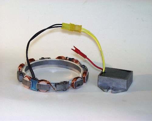
4 Alternator Identification Page 3 of 3 10 amp AC. One black lead from stator. Green connector. Two diodes encased in wire harness. Red and white output leads. Fig. 4 - Tri-Circuit Stator 5 or 9 amp DC+ regulated for charging battery. Alternator output (5 or 9 amp) is determined by flywheel alternator magnet size. Uses same stator as Tri-Circuit system. One black lead from stator. Green connector. Fig. 5-5 or 9 Amp Regulated Stator 10 or 16 amp DC regulated for charging battery. Two black leads from stator. Yellow connector with two pin terminals. Two yellow leads to regulator/rectifier. One red lead from regulator/rectifier to red connector output lead. 10 and 16 amp system use the same stator, color coding and regulator/rectifier. Alternator output is determined by the flywheel alternator magnet size. Fig or 16 Amp Regulated Stator
 sizes of alternator magnets. The size of the magnet determines the alternator output Fig. 7.")
5 Flywheel Identification Intek OHV-Twin Cylinder Flywheels have a single ring of magnets which provide the magnetic field for the various alternator systems. There are two (2) sizes of alternator magnets. The size of the magnet determines the alternator output Fig. 7. Small Magnet 22 mm x 17 mm (7/8 x 21/32) Large Magnet 22 mm x 23 mm (7/8 x 29/32) Table 2 identifies the magnet size to be used with a specific alternator system. Note: Large magnet flywheels cannot be used with the AC only, DC only, Dual Circuit and Tri-Circuit alternator systems. Alternator Small Magnet Large Magnet Fig. 7 - Alternator Magnets AC Only DC Only Dual Circuit Tri-Circuit Regulated 5 Amp Regulated 9 Amp Regulated 10 Amp Regulated 16 Amp
6 Troubleshooting The following list is provided to aid you in diagnosing problems with alternator systems. COMPLAINT "Battery not charging" Engine #1 Engine #2 "Battery overcharging" "Headlamps not working" "Electric PTO clutch not working" POSSIBLE CAUSES Engine RPM too low Inline fuse "blown" (if equipped) Defective battery Loose, pinched or corroded battery ground leads Loose, pinched or corroded battery charge leads Open, shorted or grounded wires between output conn. and battery Cyl. Defective #1 diode Cyl. (open #2 or Psi closed) Diff. %Diff. Defective or improperly grounded regulator/rectifier 65 Psi 60 Psi 60 Psi 7.6% Diode installed incorrectly (reversed) Damaged 75 Psi battery 55 Psi (shorted 20 battery Psi cells) 26.7% Excessive current draw from accessories Low magnetic flux or damaged alternator magnets Engine RPM too low Severe battery vibration (missing or broken tie-down straps) Battery amp/hour rating not matched to alternator output Damaged battery (shorted battery cells) Defective regulator/rectifier 1 Ohm resistor shorted or grounded (Tri-Circuit system only) Inline fuse "blown" (if equipped) Defective headlamps Loose or corroded wires Open, shorted or grounded wires between output conn. and lamps Defective headlamp switch Defective diode harness (Tri-Circuit) Low magnetic flux or damaged alternator magnets Inline fuse "blown" (if equipped) Loose or corroded wires Open, shorted or grounded wires between output conn. and clutch Defective diode harness (Tri-Circuit) Note: battery will not charge Defective PTO clutch switch Open, shorted PTO clutch circuit Low magnetic flux or damaged alternator magnets
7 Test Equipment The following equipment is recommended to test and repair alternators. The Digital Multimeter is available from your Briggs & Stratton source of supply. Order as Tool #19357 or # The meter may be used to read volts, ohms or amperes, and test diodes, when leads are inserted in the appropriate receptacle, Fig. 8 Fig. 8 - Digital Multimeter The Digital Multimeter will withstand DC input of amps for up to 30 seconds. When checking DC output on 16 and 20 amp regulated system, use the DC shunt, Tool #19359, to avoid blowing fuse in meter, Fig. 9. Note: The Digital Multimeter is equipped with two fuses to prevent damage to the meter in the event that the input limits are exceeded. If the meter displays a reading of 0.00 when testing DC output (A ), check fuses in meter. Refer to FLUKE Operators Manual for procedure for checking fuses. Replacement fuse is available from your Briggs & Stratton source of supply. Order Part No Fig. 9 - DC Shunt - Tool # 19359
8 Alternator Output Testing When checking alternators, make the tests in the following sequence. 1. Test alternator AC Volts output. 2. Test DC Amps output. Test diode(s) or regulator, rectifier (if equipped). Note: Before testing the alternators output (volts, amps), first use an accurate tachometer and temporarily adjust the engine speed to 3600 RPM. WARNING: UPON COMPLETION of the alternator output test, always readjust the engine rpm to its correct top no-load governed speed! Otherwise engine may exceed safe operating speed which could cause personal injury. Correct speed is found in the Service Engine Sales Manual Microfiche, MS6225 or the Service Sales Manual, MS4052.

9 AC Only Alternator The AC alternator provides current for headlights only. Current for the lights is available as long as the engine is running. The output depends upon engine speed. 12 volt lights with a total rating of 60 to 100 watts may be used. With lights rated at 70 watts, the voltage rises from 8 volts at 2400 RPM to 12 volts at 3600 RPM, so the brightness of the light changes with the engine speed. Fig. 1 - AC Only Stator

10 AC Only Alternator AC Output Test 1. Insert RED test lead into V receptacle in meter. 2. Insert BLACK test lead into receptacle in meter. 3. Rotate selector to V ~ (AC volts) position. 4. Attach RED test lead clip to AC output terminal, Fig Attach BLACK test lead clip to engine ground. 6. With engine running at 3600 RPM, AC output should be no less than 14 volts. Fig Test AC Output 7. If no or low output is found, replace the stator.

11 DC Only Alternator The DC alternator provides DC current for charging a 12 volt battery. The current from the alternator is unregulated and is rated at 3 amps. The output rises from 2 amps at 2400 RPM, to 3 amps at 3600 RPM. Recommended battery sizes range from 30 ampere hour for warm temperature service to 50 ampere hour in coldest service. When checking alternator components, make the test in the following sequence: Fig. 2 - DC Only Stator
 battery terminal. 6. With engine running at 3600 RPM, output should be between 24 amps DC. a. Output will vary with battery voltage.")
12 DC Only Alternator Alternator Output Test 1. Insert RED test lead into 10 A receptacle in meter. 2. Insert BLACK test lead into receptacle in meter. 3. Rotate selector to (DC amps) position. 4. Attach RED test lead clip to DC output terminal, Fig Attach BLACK test lead clip to positive (+) battery terminal. 6. With engine running at 3600 RPM, output should be between 24 amps DC. a. Output will vary with battery voltage. If battery voltage is at its maximum, output will be approximately 2 amps. Fig Test DC Output 7. If no or low output is found, test diode.
. An incomplete circuit (open diode) will be displayed as \"OL\". 1.")
13 DC Only Alternator Diode Test In the Diode Test position, the meter will display the forward voltage drop across the diode(s). If the voltage drop is less than 0.7 volts, the meter will Beep once as well as display the voltage drop. A continuous tone indicates continuity (shorted diode). An incomplete circuit (open diode) will be displayed as "OL". 1. Insert RED test lead into V receptacle in meter. 2. Insert BLACK test lead into receptacle in meter. 3. Rotate selector to (Diode Test) position. Fig Test Diode 4. Attach RED test lead clip to point "A" and BLACK test lead clip to point "B", Fig. 12. (It may be necessary to pierce wire with a pin as shown.) a. If meter "Beeps" once, diode is OK. b. If meter makes a continuous tone, diode is defective (shorted). Replace diode. c. If meter displays "OL", proceed to step Reverse test leads. a. If meter "Beeps" once, diode is installed backwards. Replace diode. b. If meter still displays "OL", diode is defective (open). Replace diode. 6. If diode tests OK, check stator for bare wires or other obvious defects. If grounded leads are not visible, replace the stator. Note: Service replacement diode harnesses are available. Use Resin Core solder when installing new harness. Use shrink tubing or tape all connections. Note: Do not use crimp connectors.

14 Dual Circuit Alternator Dual circuit alternators use a single polarized plug with two pins. One pin is for charging the battery and the second is for the AC light circuit. The dual circuit alternator provides DC current for battery charging and an independent AC circuit for headlights. The battery is not used for lights, so lights are available even if battery is disconnected or removed. Current for lights is available as long as the engine is running. The output depends upon engine speed, so brightness of the lights changes with engine speed. 12 volt lights with a total rating of 60 to 100 watts may be used. With lights rated at 70 watts, the voltage rises from 8 volts at 2400 RPM to 12 volts at 3600 RPM. The current from the DC side of the alternator is unregulated and is rated at 3 amps. The output rises from 2 amps at 2400 RPM to 3 amps at 3600 RPM. Fig. 3 - Dual Circuit Stator
 battery terminal. 6.")
15 Dual Circuit Alternator Alternator Output Test 1. Insert RED test lead into 10 A receptacle in meter. 2. Insert BLACK test lead into receptacle in meter. 3. Rotate selector to A (DC amps) position. 4. Attach RED test lead clip to DC output pin in connector, Fig Attach BLACK test lead clip to positive (+) battery terminal. 6. With engine running at 3600 RPM output should be between 24 amps DC. a. Output will vary with battery voltage. If battery voltage is at its maximum, output will be approximately 2 amps. 7. If no output or low output is found, test diode. Fig Test DC Output
 An incomplete circuit (open diode) will be displayed as \"OL\". 1.")
16 Dual Circuit Alternator Diode Test In the Diode Test position, the meter will display the forward voltage drop across the diode(s). If the voltage drop is less than 0.7 volts, the meter will Beep once as well as display the voltage drop. A continuous tone indicates continuity (shorted diode) An incomplete circuit (open diode) will be displayed as "OL". 1.Insert RED test lead into V receptacle in meter. 2. Insert BLACK test lead into receptacle in meter. 3. Rotate selector to (Diode Test) position. Fig Test Diode 4. Attach RED test lead clip to point "A" and BLACK test lead clip to point "B", Fig. 14. (It may be necessary to pierce wire with a pin as shown.) a. If meter "Beeps" once, diode is OK. b. If meter makes a continuous tone, diode is defective (shorted). Replace diode. c. If meter displays "OL", proceed to step Reverse test leads. a. If meter "Beeps" once, diode is installed backwards. Replace diode. b. If meter still displays "OL", diode is defective (open). Replace diode. 6. If diode tests OK, check stator for bare wires or other obvious defects. If grounded leads are not visible, replace the stator. Note: Service replacement diode harnessers are available. Use Resin Core solder when installing new harness. Use shrink tubing or tape all connections. Note: Do not use crimp connectors

17 Dual Circuit Alternator AC Output Test 1. Insert RED test lead into V receptacle in meter. 2. Insert BLACK test lead into receptacle in meter. 3. Rotate selector to V ~ (AC volts) position. 4. Attach RED test lead clip to AC output terminal, Fig Attach BLACK test lead clip to engine ground. 6. With engine running at 3600 RPM output should be no less than 14 volts AC. 7. If no output or low output is found, replace stator. Fig Test AC Output
18 Tri-Circuit Alternator The tri-circuit alternator provides alternating current through a single output lead and connector to a wiring harness containing two diodes. One diode rectifies the AC current to 5 amps negative (-) DC for lights. The second diode rectifies the AC current to 5 amps positive (+) DC for battery charging and external loads, such as an electric clutch. Note: Some equipment manufacturers supply the diodes as an integral part of the equipment wiring harness. Some equipment manufacturers use a 1 Ohm 20 watt resistor placed in series with (+) DC charging lead, limiting the charging current to approximately 3 amps when the clutch is not engaged. When the clutch is engaged the resistor is bypassed allowing full output to the battery and clutch. Note: The 1 Ohm 20 Watt resistor is supplied by the equipment manufacturer. The battery is not used for the lights, so lights are available even if the battery is disconnected or removed. Current for the lights is available as long as the engine is running. The output depends upon engine RPM, so the brightness of the lights changes with engine speed. Fig. 4 - Tri-Circuit Stator

19 Tri-Circuit Alternator Alternator Output Test 1. Insert RED test lead into V receptacle in meter. 2. Insert BLACK test lead into receptacle in meter. 3. Rotate selector to V ~ (AC volts) position. 4. Attach RED test lead clip to output terminal, Fig Attach BLACK test lead clip to engine ground. 6. With engine running at 3600 RPM, output should be no less than 28 volts AC. 7. If no output or low output is found, replace stator. 8. If alternator output is good, test diodes located in wiring harness. Fig Test Alternator Output
20 Tri-Circuit Alternator Diode Test Note: One diode is for the charging circuit and the other diode is for the lighting circuit. In the Diode Test position, the meter will display the forward voltage drop across the diode(s). If the voltage drop is less than 0.7 volts, the meter will Beep once as well as display the voltage drop. A continuous tone indicates continuity (shorted diode) An incomplete circuit (open diode) will be displayed as "OL."
 position. 4. Attach BLACK test lead clip to point A, (red wire) Fig. 17. (It may be necessary to pierce wire with a pin as shown.) 5.")
21 Tri-Circuit Alternator Diode Test Charging Circuit (Red Wire) 1. Insert RED test lead into V receptacle in meter. 2. Insert BLACK test lead into receptacle in meter. 3. Rotate selector to (Diode Test) position. 4. Attach BLACK test lead clip to point A, (red wire) Fig. 17. (It may be necessary to pierce wire with a pin as shown.) 5. Insert RED test lead probe into harness connector. a. If meter "Beeps" once, diode is OK. b. If meter makes a continuous tone, diode is defective (shorted). Replace harness. c. If meter displays "OL", proceed to step 6. Fig Diode Test - Charging Circuit 6. Reverse test leads. a. If meter "Beeps" once, diode is installed backwards. Replace harness. b. If meter still displays "OL", diode is defective (open). Replace harness.
22 Tri-Circuit Alternator Diode Test Lighting Circuit (White Wire) 1. Insert RED test lead into V receptacle in meter. 2 Insert BLACK test lead into receptacle in meter. 3. Rotate selector to (Diode Test) position. 4. Attach RED test lead clip to point "A", (white wire) Fig. 18. (It may be necessary to pierce wire with a pin as shown.) 5. Insert BLACK test lead probe into harness connector. a. If meter "Beeps" once, diode is OK. b. If meter makes a continuous tone, diode is defective (shorted). Replace harness. c. If meter displays "OL", proceed to step 6. Fig Diode Test - Lighting Circuit 6. Reverse test leads. a. If meter "Beeps" once, diode is installed backwards. Replace harness. b. If meter still displays "OL", diode is defective (open). Replace harness. Note: Service replacement diode harnesses are available.
23 5 & 9 Amp Regulated Alternator The 5 & 9 amp regulated alternator systems provide AC current through a single lead to the regulator/rectifier. The regulatorrectifier converts the AC current to DC and regulates current to the battery. The charging rate will vary with engine RPM and temperature. Alternator output (5 or 9 amp) is determined by the flywheel alternator magnet size. The stator and regulator-rectifier are the same for the 5 and 9 amp system. The 5 & 9 amp regulated system and the Tri-Circuit system use the same stator. When checking alternator components, make tests in the following sequence: Fig. 5-5 or 9 Amp Regulated Stator
 position. 4. Attach RED test lead clip to output terminal, Fig. 19. 5.")
24 5 & 9 Amp Regulated Alternator Alternator Output Test Temporarily, disconnect stator wire harness from regulator/rectifier. 1. Insert RED test lead into V receptacle in meter. 2. Insert BLACK test lead into receptacle in meter. 3. Rotate selector to V ~ (AC volts) position. 4. Attach RED test lead clip to output terminal, Fig Attach BLACK test lead clip to engine ground. Fig Test AC Output 6. With the engine running at 3600 RPM, AC output should be no less than: 28 Volts AC - 5 Amp System 40 Volts AC - 9 Amp System 7. If no or low output is found, replace the stator.

25 5 & 9 Amp Regulated Alternator Testing Regulator/Rectifier Note: Regulator/rectifier will not function unless it is grounded to engine. Make sure the regulator/rectifier is securely mounted to engine. When testing regulator/rectifier for amperage output, a 12 volt battery with a minimum charge of 5 volts is required. There will be no charging output if battery voltage is below 5 volts. Note: Connect test leads before starting engine. Be sure connections are secure. If a test lead vibrates loose while engine is running, the regulator/rectifier may be damaged. Connect stator wire harness to regulator/rectifier. Fig Test Regulator/Rectifier 1. Insert RED test lead into 10 A receptacle in meter. 2. Insert BLACK test lead into receptacle in meter. 3. Rotate selector to A (DC amps) position. 4. Attach RED test lead clip to red DC output terminal on regulator-rectifier, Fig Attach BLACK test lead clip to positive (+) battery terminal. 6. With the engine running at 3600 RPM. The output should be: * 3-5 Amps - 5 Amp System * 3-9 Amps - 9 Amp System * Depending upon battery voltage. For example, if the battery voltage was below 11 volts, the output reading would be 5 or 9 amps, depending upon the alternator system being tested. If battery voltage is at its maximum, the amperage will be less. 7. If no or low output is found, be sure that regulator/ rectifier is grounded properly and all connections are clean and secure. If there is still no or low output, replace the regulator/rectifier.

26 10 & 16 Amp Regulated Alternator The 10 or 16 amp regulated alternator system provides AC current through two output leads to the regulator/rectifier. The regulator/rectifier converts the AC current to DC, and regulates the current to the battery. The charging rate will vary with engine RPM and temperature. Alternator output (10 or 16 amp) is determined by flywheel alternator magnet size. Therefore, stator and regulator/rectifier are the same for the 10 and 16 amp system. When checking alternator components, make the tests in the following sequence: Fig or 16 Amp Regulated Stator
 position. 4. Insert RED and BLACK test lead probes into output terminals in yellow connector, as shown in Fig. 21.")
27 10 & 16 Amp Regulated Alternator Alternator Output Test Temporarily, disconnect stator wire harness from regulator/rectifier. 1. Insert RED test lead into V receptacle in meter. 2. Insert BLACK test lead into receptacle in meter. 3. Rotate selector to V ~ (AC volts) position. 4. Insert RED and BLACK test lead probes into output terminals in yellow connector, as shown in Fig. 21. (Meter test clip leads may be attached to either terminal.) 5. With the engine running at 3600 RPM output should be no less than: Fig Testing AC Output *20 Volts - 10 Amp System *30 Volts - 16 amp System *If alternator output test indicates a 16 amp system, see special instructions for testing regulator/rectifier. 6. If no or low output is found. check for bare wires or any other obvious defects. If shorted leads are not visible, replace the stator.

28 10 & 16 Amp Regulated Alternator Test Regulator/Rectifier 10 Amp System Note: Regulator/rectifier will not function unless it is grounded to engine. Make sure the regulator/rectifier is securely mounted to engine. When testing regulator/rectifier for amperage output, a 12 volt battery with a minimum charge of 5 volts is required. There will be no charging output if battery voltage is below 5 volts. Note: Connect test leads before starting engine. Be sure connections are secure. If a test lead vibrates loose while engine is running, the regulator/rectifier may be damaged. Connect stator wire harness to regulator/rectifier. 1. Insert RED test lead into 10 A receptacle in meter. 2. Insert BLACK test lead into receptacle in meter. 3. Rotate selector to A (DC amp) position. 4. Attach RED test lead clip to red DC output terminal on regulator-rectifier, Fig Attach BLACK test lead clip to positive (+) battery terminal. 6. With the engine running at 3600 RPM. The output should be: * 3-10 Amps - 10 Amp System * Depending upon battery voltage. For example, if the battery voltage was below 11 volts, the output reading would be 10 amps. If battery voltage is at its maximum, the amperage will be less. Fig Test Regulator/Rectifier 7. If no or low output is found, be sure that regulator/ rectifier is grounded properly and all connections are clean and secure. If there is still no or low output, replace the regulator/rectifier.

29 10 & 16 Amp Regulated Alternator Test Regulator/Rectifier 16 Amp System Note: The Digital Multimeter will withstand DC input of amps for up to 30 seconds. When checking DC output on 16 amp regulated system, use DC Shunt, Tool #19359, to avoid blowing fuse in meter. See special instructions for installation procedure on 16 amp system. When testing regulator/rectifier for amperage output, a 12 volt battery with a minimum charge of 5 volts is required. There will be no charging output if battery voltage is below 5 volts. Note: Connect test leads before starting engine. Be sure connections are secure. If a test lead vibrates loose while engine is running, the regulator/rectifier may be damaged. To avoid blowing fuse in meter when testing DC output of 16 amp system the DC Shunt, Tool #19359 is required. The DC Shunt must be installed on the negative (-) terminal of the battery, Fig. 23. All connections must be clean and tight for correct amperage readings. Connect stator wire harness to regulator/rectifier. 1. Install shunt on negative battery terminal. 2. Insert RED test lead into V receptacle in meter and connect to RED post terminal on shunt, Fig Insert BLACK test lead into receptacle in meter and connect to BLACK post terminal on shunt. 4. Rotate selector to 300mV position. Fig Test Regulator/Rectifier 16 Amp System With DC Shunt 5. With the engine running at 3600 RPM, the output should be: * 3-16 Amps - 16 Amp System * Depending upon battery voltage. For example, if the battery voltage was below 11 volts, the output reading would be 16 amps. If battery voltage is at its maximum, the amperage will be less. 6. If no or low output is found, be sure that regulator/ rectifier is grounded properly and all connections are clean and secure. If there is still no or low output, replace the regulator/rectifier.
30 10 & 16 Amp Regulated Alternator Page 1 of 3 Regulator/Rectifier Part #493219, Fig. 24, is used by some equipment manufacturers that have a charging indicator light instead of an ammeter. In addition to the red DC+ output wire, the regulator/rectifier is equipped with a blue wire which is used to activate a charging indicator light when battery voltage is below 12 volts. Regulator/Rectifier With Charge Indicator The charging indicator light should light when the key switch is in the ON position; engine not running. With engine running, the charging indicator light should go out, indicating that the charging circuit is operating, providing that battery voltage is above 12 volts. The charge indicator light and all wiring is supplied by the equipment manufacturer. See typical wiring diagram, page 13. Fig Regulator/Rectifier DC+ charging output values and test procedures are the same as those listed for the 10 amp or 16 amp

31 10 & 16 Amp Regulated Alternator Page 2 of 3 Typical 16 Amp regulated alternator wiring diagram - 6 pole switch with charge indicator light Regulator/Rectifier With Charge Indicator Key Switch Test Switch Position Continuity 1. OFF * RUN START * Terminal 1 Grounded internally To Key Switch Case Terminal No. Function 1 To Ground (used only with insulated panel) 2 3 To Carburetor Solenoid To Stop Switch Terminal On Engine 4 To Starter Solenoid (tab terminal) 5 To Battery (battery terminal on starter solenoid) 6 To Alternator (DC Output)

32 10 & 16 Amp Regulated Alternator Page 3 of 3 Regulator/Rectifier With Charge Indicator Testing Charge Indicator It is important that the test procedure be done in a systematic manner to identify whether the problem is related to the regulator/rectifier or the charging indicator wiring system. Follow test procedure in the sequence listed. A known good battery is required for this test. Before testing the charging indicator system, test the alternator and regulator/rectifier for proper output Note: Output values are the same as the 10 amp and 16 amp system. Symptom: Charge Indicator Light Will Not Light Key Switch On - Engine Not Running Fig Test Charge Indicator A jumper wire is required for this test. Make sure key switch is in OFF position before connecting jumper wire. Note: Before disconnecting output harness from connector, mark or identify the charging indicator wire in the output harness. If jumper wire contacts charging output wire during test, while key switch is in ON position, wiring harness may be damaged. 1. Disconnect output harness at white connector. 2. Attach one end of jumper wire to a good ground. 3. Attach other end of jumper wire to charge indicator terminal in harness connector, Fig. 25. a. Turn keyswitch to ON position. b. If bulb lights, charge indicator wiring system is OK. Replace regulator/rectifier. c. If bulb does not light, replace bulb. d. If new bulb does not light, the problem must be a broken wire (open circuit) in charging indicator circuit. Symptom: Charge Indicator Light Stays On - Engine Running Note: Indicator light will remain on if battery voltage is below 12 volts. 1. Check indicator light wiring. a. If wiring is grounded, light will remain on when engine is running. b. If wiring is OK, replace regulator/rectifier.
33 Batteries The battery is of the 12 volt, lead acid, wet cell type. This type is available as a maintenance free or a dry charged battery. The maintenance-free battery is filled with electrolyte at the time of manufacture. The level of electrolyte cannot be checked, Fig. 26. The dry charged battery is manufactured with fully charged plates. Electrolyte must be added at the time that the battery is placed in service. Before activating a dry charged battery, read and follow the manufacturers recommended procedure. Recommended battery sizes range from a minimum 30 ampere hour for warm temperature service to 50 ampere hour in coldest service. WARNING: BATTERIES PRODUCE Hydrogen, an explosive gas! Do not store, charge or use a battery near an open flame or devices which utilize a pilot light or can create a spark. Fig Typical Wet Charge Battery

34 Batteries Installation 1. Before installing battery, connect all equipment to be operated. Fig Place battery in holder with a flat base. Tighten hold downs evenly until snug. DO NOT overtighten. 3. Connect positive terminal to positive post FIRST to prevent sparks from accidental grounding. Tighten connectors securely. 4. Install protective cover over positive battery terminal ends. 5. Connect negative terminal to negative battery terminal. Tighten connectors securely. Fig Typical 12 V Wiring Diagram
35 Batteries Checking Battery 1. Physical check - clean if necessary. a. Corrosion b. Dirt c. Terminal and clamps (secure - good conditions) 2. Bring battery to full charge. Do not exceed the charge rate of 1/10 ampere for every ampere of battery rating. Consult battery manufacturer for charging recommendations. Overcharging may cause battery failure. a. Use a taper charger (automatically reduces charge rate). b. Fill battery cells with distilled water or tap water (unless maintenance free type) after charging (for batteries that have been in service). Fig Checking 12 V Battery Cells (Lead Acid, Wet Cell, With Fill Caps) Note: If battery gets hot to the touch or is spitting acid (gassing) excessively, unplug charger periodically. 3. With battery fully charged, check specific gravity readings (unless maintenance free type) of each cell with a Battery Hydrometer and record readings (Fig. 28). All readings should be above (compensating for temperature). If specific gravity readings varied.050 or if ALL cells read less than 1.225, replace battery.
Table No. 1 provides a means of identifying the various alternator systems. Note: All output figures are rated at 3600 RPM. TABLE NO.
 The alternator systems installed on Briggs & Stratton Intek OHV-Twin Cylinder Engines can easily be identified by the color of the stator output wires and the connector. Table No. 1 provides a means of
Alternator Identification
 Alternator Identification Briggs & Stratton engines are equipped with a number of different alternator systems to meet the requirements of equipment manufacturers. For example, a large lawn tractor with
another free manual from ENGINE ALTERNATOR REPLACEMENT GUIDE
 ENGINE ALTERNATOR REPLACEMENT GUIDE ThePowerPortal.com Your One Stop Information Source Briggs & Stratton has developed a powerful and flexible private web-based portal for its family of products, ThePowerPortal.com.
SECTION 1E ENGINE ELECTRICAL
 SECTION 1E ENGINE ELECTRICAL CAUTION: Disconnect the negative battery cable before removing or installing any electrical unit or when a tool or equipment could easily come in contact with exposed electrical
NOTE: SPECIFICATION TABLES BEGIN ON PAGE 41 OF THIS SECTION.
 Test Interlock Switch Wiring Model Series 0000. Disconnect interlock switch wires from spade terminals on switch and at starter motor connector.. Set meter to read ohms.. Connect one meter test lead to
16. CHARGING SYSTEM 16-0 CHARGING SYSTEM NEXXON 50
 16 16 CHARGING SYSTEM SERVICE INFORMATION------------------------------------------------ 16-2 TROUBLESHOOTING----------------------------------------------------- 16-3 BATTERY --------------------------------------------------------------------
ELECTRICAL TABLE OF CONTENTS
 ELECTRICAL TABLE OF CONTENTS Electrical Table of Contents General Information...205 Reading Electrical Schematics...205 Theory Of Operation Information...206 Diagnostic Information...206 Wire Color Abbreviation
14. BATTERY/CHARGING SYSTEM/
 14 Battery Fuse Regulator/Rectifier CDI A.C. Generator Resistors Y G/B G Y W R G A.C. Generator Headlight Switch Auto Bystarter Resistor 5Ω 5W Regulator/ Rectifier Battery 12V4AH 14 14-0 AGIKITY 50 SERVICE
Battery Operation. Battery Construction. Battery State Of Charge. Battery Load Test. Battery Rating Systems 2/14/12
 Battery Operation Batteries, Charging and Donald Jones Brookhaven College Batteries convert chemical energy into electrical energy During discharge the battery s plate composition is changed During charging
MODEL 6010A 6 12 VOLT BATTERY CHARGER ASSOCIATE
 MODEL 600A 6 VOLT BATTERY CHARGER ASSOCIATE IMPORTANT SAFETY INSTRUCTIONS. SAVE THESE INSTRUCTIONS. This manual contains important safety and operating instructions for the battery charger you have purchased.
STARTING SYSTEMS 8B - 1 STARTING SYSTEMS CONTENTS
 TJ STARTING SYSTEMS 8B - 1 STARTING SYSTEMS CONTENTS page DESCRIPTION AND OPERATION STARTER MOTOR... 2 STARTER RELAY... 3 STARTING SYSTEM... 1 DIAGNOSIS AND TESTING STARTER MOTOR... 8 STARTER MOTOR NOISE
Art. No. EC-315. Art. No. EC-330. Art. No. EC-340 SWITCH-MODE BATTTERY CHARGER CONTENTS IMPORTANT SAFETY PRECAUTIONS... 2
 SWITCH-MODE BATTTERY CHARGER CONTENTS IMPORTANT SAFETY PRECAUTIONS... 2 DESCRIPTION AND FEATURES... 3 CHARGING STAGES... 4 Art. No. EC-315 Art. No. EC-330 Art. No. EC-340 PROTECTIONS... 5 INSTALLATION...
Reproduction. Not for ADVANCE PRODUCT SERVICE INFORMATION INFORMATION BULLETIN NO: 36 DATE: 11/27/02 SUBJECT: POWERLINK SYSTEM
 ADVANCE PRODUCT SERVICE INFORMATION INFORMATION BULLETIN NO: 36 DATE: 11/27/02 SUBJECT: POWERLINK SYSTEM FILE IN: INTEK & VANGUARD REPAIR MANUAL GFCI Inverter Stator POWERLINK Harness Reset ON OFF Switch
LAWN & GARDEN PRODUCT ELECTRICAL SYSTEM INFORMATION FOR S 1612
 LAWN & GARDEN PRODUCT ELECTRICAL ELECTRICAL SYSTEM INFORMATION FOR LAWN & GARDEN PRODUCT 106 ELECTRICAL LAWN & GARDEN PRODUCT 20 & 22 BATTERY INFORMATION GENERAL INFORMATION (COURTESY OF HAWKER ENERGY
C.E. Niehoff & Co. C653/C653A and C625 Alternators Troubleshooting Guide NOTICE. Hazard Definitions. Battery Charge Volt and Amp Values
 C.E. Niehoff & Co. C653/C653A and C625 Alternators Troubleshooting Guide Hazard Definitions These terms are used to bring attention to presence of hazards of various risk levels or to important information
CHAPTER 10 ELECTRIC SYSTEM
 CHAPTER 10 ELECTRIC SYSTEM 1. ELECTRIC SYSTEM ELECTRIC SYSTEM 1.1 WIRING DIAGRAM CK20-USA 196WA00A S196-WOO Jul. 2003 10-3 CK20(M) CHAPTER 10 CK20-EU 196WA51A 10-4 S196-WOO Jul. 2003 ELECTRIC SYSTEM 1.2
THE ALT AL ERNA RN T A OR
 THE ALTERNATOR Initial Voltage of the Battery (Engine Not Running) Charging Voltage for the Battery (Engine Running) Testing for Maximum Output of the Alternator Inspecting the Regulator Positive Side
CHARGING SYSTEM 8C - 1 CHARGING SYSTEM CONTENTS
 ZG CHARGING SYSTEM 8C - 1 CHARGING SYSTEM CONTENTS page GENERAL INFORMATION OVERVIEW... 1 DESCRIPTION AND OPERATION BATTERY TEMPERATURE SENSOR... 2 CHARGING SYSTEM OPERATION... 1 ELECTRONIC VOLTAGE REGULATOR...
Automatic taper of charge rate for superior battery life through good equalization of cells and low water use rate.
 FEATURES Automatic taper of charge rate for superior battery life through good equalization of cells and low water use rate. Silicon diodes with inherent surge protection operated at a conservative percentage
ELECTRICAL / GENERAL INFORMATION
 ELECTRICAL / GENERAL INFORMATION General Information Reading Electrical Schematics The schematic is made up of individual circuits laid out in a sequence of related functions. It is formatted with all
17. BATTERY/CHARGING SYSTEM
 17 17 BATTERY/CHARGING SYSTEM CHARGING SYSTEM LAYOUT/CHARGING CIRCUIT ----------- 17-1 SERVICE INFORMATION------------------------------------------------ 17-2 TROUBLESHOOTING-----------------------------------------------------
ELECTRICAL BATTERY/STARTING/CHARGING SYSTEMS DIAGNOSTICS
 Z ELECTRICAL 8A - 1 ELECTRICAL GROUP INDEX page AUDIO SYSTEMS... 8F BATTERY/STARTER/GENERATOR SERVICE... 8B BATTERY/STARTING/CHARGING SYSTEMS DIAGNOSTICS... 8A CHIME WARNING/REMINDER SYSTEM... 8U HORNS...
SERVICE INFORMATION BATTERY/CHARGING SYSTEM XL CHARGING SYSTEM INSPECTION 15-5 REGULATOR/RECTIFIER 15-6 ALTERNATOR 15-7
 15. BATTERY/CHARGING SYSTEM SERVICE INFORMATION 15-1 TROUBLESHOOTING 15-2 BATTERY 15-3 CHARGING SYSTEM INSPECTION 15-5 REGULATOR/RECTIFIER 15-6 ALTERNATOR 15-7 SERVICE INFORMATION GENERAL t The battery
MODEL ELC-12/60-D BATTERY CHARGER
 *32198* NATIONAL RAILWAY SUPPLY Installing, Operating and Service Instructions for the 12/60 Solid State Charger MODEL ELC-12/60-D BATTERY CHARGER PLEASE SAVE THESE IMPORTANT SAFETY AND OPERATING INSTRUCTIONS
CHARGING SYSTEM 7.7 GENERAL TROUBLESHOOTING. Alternator. Voltage Regulator. Battery. Wiring. Voltage Regulator Inspection HOME
 CHARGING SYSTEM 7.7 GENERAL 8740 The charging system consists of the alternator and regulator. Charging system circuits are shown in Figure 7-5. Never install accessory wiring between battery post and
User s Manual. Automatic Switch-Mode Battery Charger
 User s Manual Automatic Switch-Mode Battery Charger IMPORTANT Read, understand, and follow these safety rules and operating instructions before using this battery charger. Only authorized and trained service
Automotive Electrical Systems
 Automotive Electrical Systems 1 Electrical Circuits Contain 4 main parts 1. Power source battery alternator 2. Load 3. Control 4. Path 2 3 Batteries What is a Battery? An electrochemical device which stores
AUTO CHARGE 11 MODEL #: XX. AUTOMATIC BATTERY CHARGER U.L. Configuration INSTRUCTION MANUAL
 INSTRUCTION MANUAL AUTO CHARGE 11 AUTOMATIC BATTERY CHARGER U.L. Configuration MODEL #: 091-11-XX NOTE : This charger is designed for vehicles with dual batteries and negative ground. CAUTION This unit
MODEL 6017 OPERATOR'S MANUAL
 MODEL 6017 OPERATOR'S MANUAL ASSOCIATE D IMPORTANT SAFETY INSTRUCTIONS 1. SAVE THESE INSTRUCTIONS. This manual contains important safety and operating instructions for the battery charger you have purchased.
C.E. Niehoff & Co. N1601, N1602, N1603, and N1604 Alternator Troubleshooting Guide NOTICE. Hazard Definitions. Battery Charge Volt and Amp Values
 C.E. Niehoff & Co. N1601, N1602, N1603, and N1604 Alternator Troubleshooting Guide Hazard Definitions These terms are used to bring attention to presence of hazard(s) of various risk levels or to important
C802/C802D/C802TD/C820 Alternators Troubleshooting Guide
 C802/C802D/C802TD/C820 Alternators Troubleshooting Guide Hazard Definitions These terms are used to bring attention to presence of hazards of various risk levels or to important information concerning
1. SPECIFICATION
 000000 093 1. SPECIFICATION Specification HPS EPS Alternator Crankshaft pulley : Alternator Pulley 1 : 2.94 Normal output (idling/2200 rpm) 70/120 A 70/140A Regulator voltage 14.6 V Brush Length 12.5 mm
21. BATTERY/CHARGING SYSTEM (After '05)
") 21. BATTERY/CHARGING SYSTEM (After '05) COMPONENT LOCATION 21-2 SYSTEM DIAGRAM (TRX450ER) 21-2 SERVICE INFORMATION 21-3 TROUBLESHOOTING 21-5 BATTERY (TRX450ER) 21-6 CHARGING SYSTEM INSPECTION (TRX450ER)
21. BATTERY/CHARGING SYSTEM (After '05) COMPONENT LOCATION 21-2 SYSTEM DIAGRAM (TRX450ER) 21-2 SERVICE INFORMATION 21-3 TROUBLESHOOTING 21-5 BATTERY (TRX450ER) 21-6 CHARGING SYSTEM INSPECTION (TRX450ER)
16. BATTERY/CHARGING SYSTEM/
 16 16 BATTER/CHARGING SYSTEM/ SERVICE INFORMATION------------------------------------------------ 16-2 TROUBLESHOOTING----------------------------------------------------- 16-3 BATTERY --------------------------------------------------------------------
IMPORTANT SAFETY INSTRUCTIONS
 1163714 1.5 AMP 12VOLT TRICKLE 1.5 AUTOMATIC AMP AUTOMATIC TRICKLE 1.5 AMP AUTOMATIC 12V12VOLT BATTERY CHARGER IMPORTANT SAFETY INSTRUCTIONS 1. SAVE THESE INSTRUCTIONS This product offers a wide range
BATTERY 8A - 1 BATTERY CONTENTS
 TJ BATTERY 8A - 1 BATTERY CONTENTS page DESCRIPTION AND OPERATION BATTERY... 1 DIAGNOSIS AND TESTING BATTERY... 3 SERVICE PROCEDURES BATTERY CHARGING... 13 DESCRIPTION AND OPERATION BATTERY DESCRIPTION
with lcd display 12-42v
 instructions for: AUTO PROBE with lcd display 12-42v MODEL No: PP7 Thank you for purchasing a Sealey product. Manufactured to a high standard this product will, if used according to these instructions
801 BUSINESS CENTER DRIVE MOUNT PROSPECT, ILLINOIS Ext. 322
 277-999 ELECTRIC CORP. 801 BUSINESS CENTER DRIVE MOUNT PROSPECT, ILLINOIS 800-621-5485 Ext. 322 Send Warranty Product Repairs to: 605 South Vermilion, Suite C, Brownsville, TX 78521-6851 Call Customer
BATTERY 8A - 1 BATTERY CONTENTS
 ZJ BATTERY 8A - 1 BATTERY CONTENTS page GENERAL INFORMATION INTRODUCTION... 1 OVERVIEW... 1 DESCRIPTION AND OPERATION BATTERY MOUNTING... 3 BATTERY SIZE AND RATINGS... 2 BATTERY... 2 DIAGNOSIS AND TESTING
N1387 Series Troubleshooting Guide for N Alternators
 N1387 Series Troubleshooting Guide for N1387-1 Alternators Hazard Definitions These terms are used to bring attention to presence of hazards of various risk levels or to important information concerning
C627, C628, C631, C656, C657, C658, C671 and C680 Alternator Troubleshooting Guide
 C627, C628, C631, C656, C657, C658, C671 and C680 Alternator Troubleshooting Guide Hazard Definitions These terms are used to bring attention to presence of hazards of various risk levels or to important
Troubleshooting Guide for N1225-1/N1237-1/N Alternators
 Troubleshooting Guide for N1225-1/N1237-1/N1505-1 Alternators Hazard Definitions These terms are used to bring attention to presence of hazards of various risk levels or to important information concerning
ELECTRICAL EQUIPMENT 15-0 ZX / SCOUT 50
 15 15 ELECTRICAL EQUIPMENT SERVICE INFORMATION... 15-1 TROUBLESHOOTING... 15-1 CHARGING SYSTEM... 15-3 BATTERY... 15-4 IGNITION SYSTEM... 15-7 STARTING SYSTEM... 15-11 15-0 SERVICE INFORMATION GENERAL
SYMPTOM POSSIBLE CAUSES CORRECTIVE ACTION. Batteries Battery connections
 ELECTRICAL SYSTEM AND TESTING TROUBLESHOOTING GUIDE 2 Troubleshooting 11 TROUBLESHOOTING GUIDE 2 SYMPTOM POSSIBLE CAUSES CORRECTIVE ACTION Vehicle does not operate Batteries Batteries discharged Charge
2/10/50 AMP 12 VOLT BATTERY CHARGER/ ENGINE STARTER
 2/10/50 AMP 12 VOLT BATTERY CHARGER/ ENGINE STARTER WARNING This product contains or, when used, produces a chemical known to the State of California to cause cancer and birth defects or other reproductive
MODEL ELC-12/40-CVM-D BATTERY CHARGER
 NATIONAL RAILWAY SUPPLY MODEL ELC-12/40-CVM-D BATTERY CHARGER Installing, Operating and Service Instructions for the ELC-12/40-CVM-D Solid State Charger PLEASE SAVE THESE IMPORTANT SAFETY AND OPERATING
ST Charger. Industrial Battery Charger
 ST Charger Industrial Battery Charger Installation and Operation Manual ST_13 Table of Contents Pg# 1.0 INSTALLATION 1 1.1 Receiving 1 1.2 Location 1 1.3 Line Voltage 1 1.4 A.C. Service Requirements 2
AUT 125 ELECTRICAL II CH 54 & 55 CHARGING SYSTEMS
 Name: Class: Date: AUT 125 ELECTRICAL II CH 54 & 55 CHARGING SYSTEMS Multiple Choice Identify the choice that best completes the statement or answers the question. 1. Technician A says that the diodes
SERVICE BULLETIN REFERENCES 1983
 J a I) SERVICE BULLETIN REFERENCES 1983 19.35 TROUBLE SHOOTING Engine Won t Start or Hard Starting Possible Cause ALL MODELS No fuel in tank. Fuel valve off. Insufficient or excessive priming. Spark plug
BATTERY 8A - 1 BATTERY TABLE OF CONTENTS
 DN BATTERY 8A - 1 BATTERY TABLE OF CONTENTS page DESCRIPTION AND OPERATION BATTERY...1 BATTERY CABLES...3 BATTERY HOLD DOWNS...4 BATTERY TRAY...4 DIAGNOSIS AND TESTING BATTERY...5 BATTERY CABLES...14 SERVICE
TROUBLESHOOTING GENERATOR UNITS
 TROUBLESHOOTING GENERATOR UNITS Figure 3.17 Troubleshooting Flow Chart For Direct Excited (Brush Type) Generators or later. 68 Troubleshooting Direct Excited (Brush Type) Generators Refer to Figure 3.17
STARTING & CHARGING SYSTEM
 K ELECTRICAL SECTION SC A STARTING & CHARGING SYSTEM B C D CONTENTS E PRECAUTIONS... 2 Precautions for Supplemental Restraint System (SRS) AIR BAG and SEAT BELT PRE-TEN- SIONER... 2 Precautions for Power
Starter, Delco Remy 15.01
 Starter, Delco Remy.0 General Information General Information The Delco Remy starter mounts at the forward face of the flywheel bell housing on the right side of the engine. The starter assembly consists
N1233 Series Troubleshooting Guide for N Alternator
 N1233 Series Troubleshooting Guide for N1233-2 Alternator Hazard Definitions These terms are used to bring attention to presence of hazards of various risk levels or to important information concerning
ELECTRICAL. CDTA Technical Training Center
 ELECTRICAL ATOMIC STRUCTURE Protons positive charge Electron negative charge Neutron - neutral Electricity is the movement of electrons from atom to atom ELECTRON FLOW CONDUCTOR - Materials which have
STARTING & CHARGING SYSTEM SECTIONSC CONTENTS IDX
 STARTING & CHARGING SYSTEM SECTIONSC GI MA EM LC EC CONTENTS FE PRECAUTIONS...2 Supplemental Restraint System (SRS) AIR BAG and SEAT BELT PRE-TENSIONER...2 Wiring Diagrams and Trouble Diagnosis...2 BATTERY...3
2008 Toyota RAV ELECTRICAL Charging (2AZ-FE) - RAV4
 - RAV4") 2008 ELECTRICAL Charging (2AZ-FE) - RAV4 CHARGING SYSTEM PRECAUTION 1. Check that the battery cables are connected to the correct terminals. 2. Disconnect the battery cables if a quick charge is given
2008 ELECTRICAL Charging (2AZ-FE) - RAV4 CHARGING SYSTEM PRECAUTION 1. Check that the battery cables are connected to the correct terminals. 2. Disconnect the battery cables if a quick charge is given
BEST 6042 BATTERY TESTER
 ASSOCIATED BEST 6042 BATTERY TESTER OPERATOR AND SAFETY MANUAL The BEST 6042 is designed to test electrical systems on 12, 12/24, and 24 volt vehicles. It can test and evaluate starters, batteries, alternators,
12V 1 AMP (1000 ma) Automatic Battery Charger & Maintainer
 Automatic Battery Charger & Maintainer") 12V 1 AMP (1000 ma) Automatic Battery Charger & Maintainer For lead-acid batteries THIS MANUAL CONTAINS IMPORTANT SAFETY AND OPERATING INSTRUCTIONS FOR 12V BATTERY CHARGER: YUA1201000 / INT1201000 KEEP
12V 1 AMP (1000 ma) Automatic Battery Charger & Maintainer For lead-acid batteries THIS MANUAL CONTAINS IMPORTANT SAFETY AND OPERATING INSTRUCTIONS FOR 12V BATTERY CHARGER: YUA1201000 / INT1201000 KEEP
Technical Information and Diagnostic Guide
 Technical Information and Diagnostic Guide This guide will assist you in becoming more familiar with the working components of the NITE System and the proper steps and procedures to completely diagnose
10AMP FULLY AUTOMATIC 6V & 12V BATTERY CHARGER OWNER'S MANUAL
 1244502 10AMP FULLY AUTOMATIC 6V & 12V BATTERY CHARGER OWNER'S MANUAL 1. IMPORTANT SAFETY INSTRUCTIONS 1.1 SAVE THESE INSTRUCTIONS This manual contains important safety and operating instructions. 1.2
AUTO CHARGE 12 AUTOMATIC BATTERY CHARGER
 INSTRUCTION MANUAL FILE: 091-165-12 reve Rev: E, page 8 DATE: 7-02-15 AUTO CHARGE 12 AUTOMATIC BATTERY CHARGER MODEL #091-165-12 NOTE : This charger is designed for vehicles with a single battery and negative
Main 20 A fuse has blown (2) Connector has come off PCB
 Connector has come off PCB") ELECTRICAL FAULT FINDING OMS TRACTORS C & A from September 00 D&K series from April 00 JCB from Jan 00 Note: This Bulletin must be used in conjunction with the correct wiring diagram for the Tractor being
ELECTRICAL FAULT FINDING OMS TRACTORS C & A from September 00 D&K series from April 00 JCB from Jan 00 Note: This Bulletin must be used in conjunction with the correct wiring diagram for the Tractor being
801 BUSINESS CENTER DRIVE MOUNT PROSPECT, ILLINOIS
 280-600 Send Warranty Product Repairs to: 1025 E. Thompson Ave., Hoopeston, IL 60942-0280. Call Customer Service if you have questions: 1-800-621-5485 A. IMPORTANT SAFETY INSTRUCTIONS 1. SAVE THESE INSTRUCTIONS
Unit AE01K Knowledge of Locating and Correcting Simple Electrical Faults in the Automotive Workplace
 Assessment Requirements Unit AE01K Knowledge of Locating and Correcting Simple Electrical Faults in the Automotive Workplace Content: Basic electrical principles a. Explain the direction of current flow
Alternator, Leece-Neville 15.00
 Alternator, Leece-Neville 5.00 General Information General Description The Leece-Neville JB series alternator is a 4-volt self-load-limiting alternator equipped with a threestep adjustable voltage regulator.
OWNER S MANUAL. Model YUA2AMPCH 2 AMP Dual-Bank Automatic Battery Charger & Maintainer READ ENTIRE MANUAL BEFORE USING THIS PRODUCT
 Model YUA2AMPCH 2 AMP Dual-Bank Automatic Battery Charger & Maintainer Certified by California BCS Regulations OWNER S MANUAL READ ENTIRE MANUAL BEFORE USING THIS PRODUCT READ ENTIRE MANUAL BEFORE USING
2000 F-150 Workshop Manual
 Page 1 of 14 SECTION 303-06: Starting System 2000 F-150 Workshop Manual DIAGNOSIS AND TESTING Procedure revision date: 06/17/1999 Starting System Refer to Wiring Diagrams Cell 20, Starting System for schematic
Electronic Service Manuals
 Electronic Service Manuals This electronic document is provided as a service to our customers. We do not create the contents of the information contained in this document. Should you have detailed questions
Series 1000 and Figure NOTE: The top terminals are showing normally closed at rest and the middle terminals are normally
 38.18.The red wire on the OCR plug carries battery voltage. Behavior: D.C. battery voltage should show-up on a volt meter when the red probe is touched to this terminal and the black probe is grounded,
518xi, 520xi & 522xi GARDEN TRACTOR
 FORM NO. 96 58xi, 50xi & 5xi GARDEN TRACTOR MODEL NO. 77 990000 & UP MODEL NO. 75 990000 & UP MODEL NO. 756 990000 & UP SET UP INSTRUCTIONS Loose Parts Use the chart below to identify parts for assembly.
TD80 LEVEL GAUGING & OVERFILL PREVENTION SYSTEM PRODUCT MANUAL. TPM 001 Revision 0.1
 TD80 LEVEL GAUGING & OVERFILL PREVENTION SYSTEM PRODUCT MANUAL Revision 0.1 3 TD80 and Overfill Prevention System Troubleshooting Equipment Required: 1. Automotive Test light, 6VDC to 24VDC 2. Short length
1. SPECIFICATION Typ. HPS EPS Capacity 120 A 140 A. 76/140 A at 1,800/6,500 rpm. 70/120 A at 1,800/6,500 rpm. Normal output.
 145300 093 1. SPECIFICATION Typ. HPS EPS Capacity 120 A 140 A Alternator Battery Normal output 70/120 A at 1,800/6,500 rpm 76/140 A at 1,800/6,500 rpm Regulator voltage 14.6 V Brush Length 12.5 mm Wear
2001 Cougar Workshop Manual
 Page 1 of 7 SECTION 303-06: Starting System 2001 Cougar Workshop Manual DIAGNOSIS AND TESTING Procedure revision date: 09/14/2001 Starting System Refer to Wiring Diagrams Section 303-06 for schematic and
UNIT 3: GENErAL ELECTriCAL SySTEM DiAGNOSiS
 Electrical/Electronic Systems UNIT 3: GENErAL ELECTriCAL SySTEM DiAGNOSiS LESSON 3: TEST electrical circuits I. Types of electrical circuit tests and electrical faults A. Different types of electrical
ALTERNATOR - HITACHI
 ALTERNATOR - HITACHI 1986 Isuzu Trooper II 1986 Alternators & Regulators HITACHI ALTERNATORS Isuzu DESCRIPTION Hitachi alternators are conventional 3-phase, self-rectifying alternators. Three positive
CHARGING SYSTEM 8C - 1 CHARGING SYSTEM CONTENTS
 TJ CHARGING SYSTEM 8C - 1 CHARGING SYSTEM CONTENTS page DESCRIPTION AND OPERATION BATTERY TEMPERATURE SENSOR... 2 CHARGING SYSTEM OPERATION... 1 ELECTRONIC VOLTAGE REGULATOR... 2 GENERATOR... 1 DIAGNOSIS
12V Manual Battery Charger & Engine Starter
 OPERATOR S MANUAL 12V Manual Battery Charger & Engine Starter Model No. 28.71230 Read and follow all Safety Rules and Operating Instructions before Every Use of this Product. Save these instructions. Sears
MINE CHARGER INSTALLATION AND OPERATION MANUAL MODEL NUMBERS: MSP MSQ MSR MSS
 MINE CHARGER INSTALLATION AND OPERATION MANUAL MODEL NUMBERS: MSP MSQ MSR MSS Sec# Table of Contents Pg# 1 INSTALLATION 1.1 Receiving 1 1.2 Location 1 1.3 Line Voltage Adjustments 2 1.4 A.C. Service Requirements
QSSE, QSSEX INDUSTRIAL Battery Chargers
 C O R P O R A T IO N O P E R A T I N G I N S T R U C T I O N S QSSE, QSSEX INDUSTRIAL Battery Chargers INTRODUCTION The QSE line are electronically controlled float chargers. The batteries are brought
Troubleshooting Guide
 Troubleshooting Guide P/N 0153180 July 1999 P.O. Box 1160 St. Joseph, MO 64502-1160 1-800-255-0317 Fax: 816-360-9379 www.snorkelusa.com GENERAL INFORMATION This manual contains procedures for locating
able of Contents Sr. No: Content Page No: 1. A: Apply Safety Precautions and Guidelines at Workplace 5 2. B:Repair Lighting System of Vehicle 6
 able of Contents Sr. No: Content Page No: 1. A: Apply Safety Precautions and Guidelines at Workplace 5 2. B:Repair Lighting System of Vehicle 6 3. C:TestBattery Performance 9 4. D: Install and Repair Starting
SP6. Automatic Battery Charger. Model
 Model SP6 Automatic Battery Charger OWNERS MANUAL PLEASE SAVE THIS OWNERS MANUAL AND READ BEFORE EACH USE. This manual will explain how to use the charger safely and effectively. Please read and follow
Installation Operation Parts
 OWNER S MANUAL BATTERY BACKUP SUMP Installation Operation Parts For further operating, installation or maintenance assistance, Call 98-8-05 PRINTED IN U.S.A. M-8 (/9) RULES FOR SAFE INSTALLATION AND OPERATION
15. ELECTRICAL EQUIPMENT
 15 15 ELECTRICAL EQUIPMENT SERVICE INFORMATION... 15-1 TROUBLESHOOTING... 15-1 CHARGING SYSTEM... 15-3 BATTERY... 15-4 IGNITION SYSTEM... 15-7 STARTING SYSTEM... 15-11 15-0 SERVICE INFORMATION GENERAL
SECTION 7 3 DO IT YOURSELF MAINTENANCE MR2 U. Electrical components
 DO IT YOURSELF MAINTENANCE Electrical components SECTION 7 3 Checking battery condition.................................. 178 Battery recharging precautions............................... 179 Checking
Section 4 GOV. CONTROLS & GOVERNOR
 Section 4 GOV. CONTROLS & Page GENERAL INFORMATION................................................................ 1 REMOTE CONTROLS Section Contents Speed Regulation.................................................................
ALTERNATOR PRECAUTIONS. Some precautions should be taken when working on this, or any other, AC charging system.
 The alternator charging system is a negative (-) ground system which consists of an alternator, a regulator, a charge indicator, a storage battery and wiring connecting the components, and fuse link wire.
GRD502-B Flow Chart 02/05/09
 PINPOINT TEST A: NO PROVE OUT OF ANY LEDs prove out (all LED's light up) of the LED's when module power is applied or module "wakes up", indicates that: - the Guardian module does not have power. - the
WARNING This manual should only be used by a qualified Service Technician. FinishPro 390/395 Airless/Air-Assisted Sprayer Repair Electrical Manual
 FinishPro 390/395 Airless/AirAssisted Sprayer Repair Electrical Manual First choice when quality counts. Rev. B 10/11 /07 FinishPro 395 3.00 ti9026a Red Yel Yel Air Hose Connection FinishPro 390 Exhaust
Electrical Systems. Introduction
 Electrical Systems Figure 1. Major Components of the Car s Electrical System Introduction Electricity is used in nearly all systems of the automobile (Figure 1). It is much easier to understand what electricity
STARTING/CHARGING SYSTEMS Brought to you by Eris Studios NOT FOR RESALE
 STARTING/CHARGING SYSTEMS General Description 1. General Description A: SPECIFICATION Vehicle model Starter Generator Item Specification Type Reduction type Model 428000-5760 Manufacturer DENSO Voltage
MAGNETO REPLACEMENT TWIN CYLINDER MOTORCYCLES ELECTRONIC IGNITION SYSTEM FOR 4 STROKE WITH 6 VOLT ELECTRICS, POS/ NEG EARTH SYSTEM TYPE: PAMT1-6
 Sure ー Fire MAGNETO REPLACEMENT ELECTRONIC IGNITION SYSTEM FOR 4 STROKE TWIN CYLINDER MOTORCYCLES WITH 6 VOLT ELECTRICS, POS/ NEG EARTH SYSTEM TYPE: PAMT1-6 Sure-Fire Applications BRITISH 4 STROKE TWIN
SECOND GENERATION Use this guide with unit serial number prefix beginning with BWF using Terra Power separator.
 Technical Information and Diagnostic Guide for SECOND GENERATION Use this guide with unit serial number prefix beginning with BWF using Terra Power separator. This guide will assist you in becoming more
Models: SP3, SPSS3 Automatic Battery Charger
 OWNERS MANUAL Models: SP3, SPSS3 Automatic Battery Charger PLEASE SAVE THIS OWNERS MANUAL AND READ BEFORE EACH USE. This manual will explain how to use the charger safely and effectively. Please read and
2003 Explorer/Mountaineer Workshop Manual
 Page 1 of 11 SECTION 414-00: Battery and Charging System 2003 Explorer/Mountaineer Workshop Manual DIAGNOSIS AND TESTING Procedure revision date: 06/18/2002 Charging System Printable View (257 KB) Refer
MODEL No s: PP3, PP3K
 instructions for: Power PROBE 3 12-24v MODEL No s: PP3, PP3K Thank you for purchasing a Sealey product. Manufactured to a high standard this product will, if used according to these instructions and properly
26 SI HEAVY DUTY BRUSHLESS ALTERNATOR SERVICE MANUAL 1G-287 PRODUCT INFORMATION 1/98 26-SI ALTERNATOR 1G/287 4/96 PAGE
 26-SI ALTERNATOR G/287 4/96 PAGE G-287 PRODUCT INFORMATION /98 26 SI HEAVY DUTY BRUSHLESS ALTERNATOR SERVICE MANUAL 998 Delco Remy International Inc. All Rights Reserved. PAGE G-287 4/96 26-SI ALTERNATOR
CHAPTER 10 ELECTRICAL
 CHAPTER 10 ELECTRICAL GENERAL INFORMATION............................................... 10.3 SPECIAL TOOLS / ELECTRICAL SERVICE NOTES.......................... 10.3 COMPONENTS UNDER HOOD / BEHIND DASH
500 Series Troubleshooting Guide for C520 Alternators
 500 Series Troubleshooting Guide for C520 Alternators Hazard Definitions These terms are used to bring attention to presence of hazards of various risk levels or to important information concerning product