Starting Systems & Traction Motor Systems. ATASA 5 th. ATASA 5 TH Study Guide Chapter 18 Pages Starting & Traction Motor Systems 62 Points
|
|
|
- Cecily Owens
- 5 years ago
- Views:
Transcription

1 ATASA 5 TH Study Guide Chapter 18 Pages Starting & Traction Motor Systems 62 Points Please Read The Summary


2 1. Electric are used to start the engine & in hybrids are used to move the vehicle. Motors are also used to operate many different accessories requiring either linear or rotary motion.

3 2. Starter motors & accessory motors use voltage while traction or drive motors use voltage. Low, High High, Low Medium, Medium


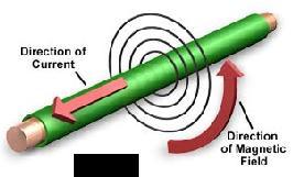

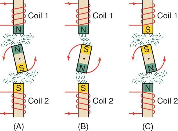
4 3. & are closely related because one can be used to create the other. Electricity & Magnetism


5 4. flow through a wire creates a magnetic field & moving a through a magnetic field creates current flow in the wire. Coils or loops of wire just intensify that effect. Voltage, Magnet Current, Coil Voltage, Coil

6 5. A magnetic field called, called a, exists around every magnet. Flux Field Plowed Field Flux Density
 are made of")

7 6. Temporary magnets (armatures) are made of iron. Permanent magnets require hard iron. Hard Medium Soft


8 7. The resistance that a material offers to passage of magnetic flux lines is called. Resistance Reactance Reluctance


9 8. Air has reluctance. Soft iron cores & armatures have reluctance. Low, High High, Low Medium, Medium


10 9. An electric motor converts energy into energy. Chemical, Mechanical Electrical, Mechanical Heat, Light

11 10. Basic components of a motor are the stator or windings, & the rotor or. Field, Armature Armature, Field Rotor, Stator

12 11. Either the field windings or the armature can be made of magnets, but not both. Permanent Electro Ceramic

13 12. The starting motor is designed to operate under great for short periods of time. Overloads Stress Capacitance
 & their")

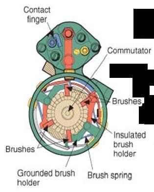
14 13. The starter frame holds the stationary coils (flat copper) & their shoes (soft iron). Pole, Vault Field, Event Field, Pole Magnetic fields Magnetic poles

15 14. The is the rotating part of the starter, made up of windings and the commutator. Armature Rotor Stator

16 15. Starter connect the armature & the field coils in either a series or parallel arrangement. Clutches Brushes Bushings
17 16. magnetic fields cause the motor armature to rotate. Repelling Rotating Reacting


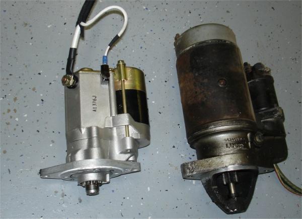
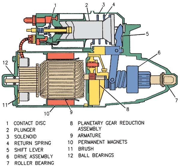
18 17. magnet starter motors may have a planetary gear reduction to increase torque. Permanent Temporary Electro


19 18. The slower the motor turns, the current it will draw. Maximum current is drawn when it is engaged, but armature is not rotating. Less Same More
20 19.The starting system has two distinct circuits: 1) the (motor feed high amps) circuit, 2) the (low amps switching) circuit. Starter, Control Starter, Solenoid Solenoid, Control


21 ** Explain how a starter solenoid can be part of both circuits: The Pull in Winding is part of the control circuit. The Plunger Contacts are part of the motor feed circuit.

22 20. The motor feed circuit contains the battery & cables, the, & the starter motor. Relay Solenoid Fusible Link
23 21. The control circuit contains the switch, starting switch, a or a solenoid (to use low amps to control higher amps), the battery, fuses, and normal gauge wiring. Ignition, Safety, Relay Parking, Key, Pedal Radio, Dome Light, Key


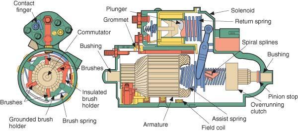
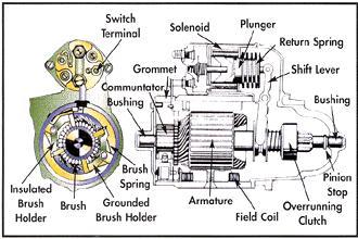
24 22. The plunger is used to move the starter pinion gear & its contacts serve as a relay switch to energize the motor once the drive pinion engages the flywheel/flex plate ring gear. Solenoid Relay Stator

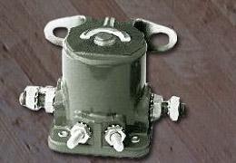
25 23. A starter is similar to a solenoid, switches high current using low current, but does not pull in a plunger to actuate a starter drive. Armature Relay Stator


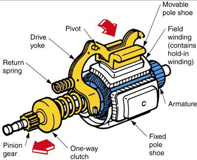
26 24. A movable starter does not use a starter motor mounted solenoid. Pole Shoe Brake Shoe Horse Shoe
27

28 Note: Corroded battery cables can lead to increased resistance and a voltage drop in the motor feed circuit. Frayed positive cables can lead to a short to ground and serious electrical damage.


29 Note: A fusible link or a maxi fuse in the motor feed circuit never blows without a reason The reason is increased amperage flow due to a decrease in resistance (like a short to ground).
30
31 ** Explain how a solenoid is similar in operation to a relay: Both solenoids & relays energize a low amps coil to close a circuit that will switch higher amps.


32 ** Explain how as solenoid differs from a relay: The starter relay uses a coil & contact points & switches smaller amps. The starter solenoid uses a hollow coil & a plunger & switches higher amps.


33 Solenoid may also move a starter drive into mesh with the flywheel ring gear. Relay doesn t have the plunger or the power to move a starter drive

34 15 Teeth on Pinion 150 Teeth on Flywheel 10:1 Gear Reduction Reduction in Speed Gain in torque

35 Note: Solenoids may have both a pull in and a hold in winding. Cranking systems may use both a starter relay and a starter solenoid.
36

37 Note: Some solenoids (older cars) provide a 12 volt source to the ignition coil during cranking.
38
39

40
41
42
43

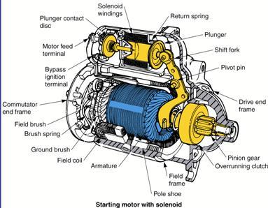
44 Pole Shoes Field Windings

45 Starter Armature Assembly
 and a brush end frame (metal")
46 Note: The starter motor has both a drive end frame (casting) and a brush end frame (metal cap).

47 The stationary magnetic fields the field windings repel the armature windings to create rotary motion.
.")
48 Note: The slower a starter motor turns, the more current it will draw (CEMF). Copper Brushes are used to carry lots of amps with very little resistance.
49 Note: Series wound motors develop maximum torque at startup. Shunt or parallel wound motors develop less torque at start up but maintain a constant speed at all operating loads.
50 The starter drive pinion gear meshes with the flywheel or flex plate ring gear to provide the necessary gear reduction to crank the engine. Ratio is greater than 1:1 with a gain in torque & a loss of speed
51 25. To prevent the pinion gear from driving the armature at engine speed an clutch is built into the starter drive mechanism. One Way Overrunning Roller


52 26. Starter drive to ring gear ratio is a gear reduction to provide a torque increase. True or False
53 Note: The starter drive fork or lever and the solenoid spring are responsible for pulling the pinion out of engagement after cranking. 15:1 is the approximate starter pinion : flywheel ring gear ratio
54 27. The starting safety switch allows the control circuit to be energized only if the automatic trans is in either the or position and only if the manual transmission has the clutch pedal fully pushed to the floor to disengage the transmission from the engine. 1 st or 2 nd Park or Neutral Park or Reverse
55


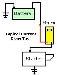
56 28. Perform a load test before performing any starting system tests. Note: Loose or dirty connections will cause excessive voltage drops in the motor feed circuit. Battery Parasitic Accessory
57 29. Battery volts should not drop below volts during the 15 seconds of cranking voltage test volts 9.6 volts 3.0 volts
58 30. Cranking current (amperage) should be between amps for most gas engines. True or False
59 31. A voltage drop test of both the side (+ to+) and the ground side ( to ) of the motor feed circuit should show between 0.2 to 0.6 volts if the battery/starter cables are in good condition. Uninsulated Insulated Resistive + + +

60 32. Starter solenoids can be by passed or jumped to verify their condition. True or False
61 33. Ignition switches can be by passed or jumped to verify their condition. True or False
 of the wiring. Good, low amps circuits should be under 0.2 VD.")
62 34. Even the low amps, control circuit can be (+ to +) tested during cranking to determine the condition (resistance) of the wiring. Good, low amps circuits should be under 0.2 VD. Amperage Drop Resistance Drop Voltage Drop

63 33. A starter no load or free speed bench test can be low on RPM s if a pole drags against the armature. This could be caused by a loose shoe or by worn drive and brush end bushings. Shoe Pad Drum


64 34. When testing an armature with a growler, a vibrating strap indicates a armature, continuity from commutator bars to the armature frame indicates a prematurely grounded motor, and no continuity from commutator bar to commutator bar indicates an condition which will result in dead spots during cranking. Open Shorted High Resistance


65 35. should be of the proper length, commutator bars should be smooth, and the mica strips of insulation between the commutator bars should be properly undercut to a uniform depth. Brushes Bushings Commutators


66 36. Starter drive on the armature shaft and both armature should be lightly lubricated with high temperature grease during rebuilding procedures. Splines, Bushings Splines, Brushes Splines, Commutator Bars Bushing Splines
67
68
69 ** Cranking Circuit schematically drawn with solenoid. M Battery +
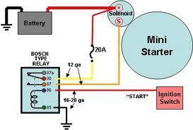
70 ** Cranking Circuit schematically drawn with relay & solenoid. M Battery a 86 30
71 Connect this meter for battery OCV V V A 12.6 V Ω OFF V Ω C OM A A M Battery + V 0.2 V Ω A V A OFF V Ω C OM A Connect this meter for control circuit Voltage Drop
72 Connect this meter for motor feed voltage drop V 0.2 V Ω A V OFF A V Ω A C OM M Battery a V 200 A Ω A V OFF A V Ω A C OM Inductively connect this meter to measure starter current draw

73 Watching Cranking Amps on a Scope can actually show a cylinder with low compression characterized by a lower current draw that repeats on the same cylinder
2006 MINI Cooper S GENINFO Starting - Overview - MINI
 MINI STARTING SYSTEM * PLEASE READ THIS FIRST * 2002-07 GENINFO Starting - Overview - MINI For information on starter removal and installation, see the following articles. For Cooper, see STARTER WITH
Battery Operation. Battery Construction. Battery State Of Charge. Battery Load Test. Battery Rating Systems 2/14/12
 Battery Operation Batteries, Charging and Donald Jones Brookhaven College Batteries convert chemical energy into electrical energy During discharge the battery s plate composition is changed During charging
STARTING SYSTEMS 8B - 1 STARTING SYSTEMS CONTENTS
 TJ STARTING SYSTEMS 8B - 1 STARTING SYSTEMS CONTENTS page DESCRIPTION AND OPERATION STARTER MOTOR... 2 STARTER RELAY... 3 STARTING SYSTEM... 1 DIAGNOSIS AND TESTING STARTER MOTOR... 8 STARTER MOTOR NOISE
Starting Systems. State a major safety precaution when removing or working around a starting motor
 Starting Systems State a major safety precaution when removing or working around a starting motor Always unhook the battery ground before attempting to remove the starter motor. Starting Systems Identify
Just what is a starter?
 Just what is a starter? The car starter works by harnessing the power of the automotive battery. The battery supplies electricity to the starter to engage and spin over the engine. Once the ignition key
 1 of 16 1/10/2015 7:25 AM STARTER MOTOR 2009 Hyundai Accent 1.6L Eng GS REQUESTED INFORMATION DISASSEMBLY 1. Disconnect the M-terminal (A) on the magnet switch assembly (B). Fig 1: Identifying M-Terminal
STARTER - HITACHI Isuzu Trooper II DESCRIPTION TESTING STARTER PERFORMANCE TESTS Starters HITACHI. Isuzu
 STARTER - HITACHI 1986 Trooper II 1984 Starters HITACHI DESCRIPTION Starter is a conventional 12-volt, 4-pole brush-type motor, with direct or reduction gear drive. The starter-mounted solenoid shifts
SECTION 9 CRANKING SYSTEM CONTENTS
 SECTION 9 CRANKING SYSTEM CONTENTS 9-1. 9-2. 9-3. 9-4. 9-5. 9-6. 9-7. 9-8. GENERAL DESCRIPTION.,...,..., 9-2 SPECIFICATIONS.......................................... 9-4 LUBRICATION 9-5 REMOVAL AND INSTALLATION...
STARTER SYSTEM TESTING 5.6
 STARTER SYSTEM TESTING 5.6 ON-MOTORCYCLE TESTS Starter Relay Test NOTE Starter relay test also applies to ignition and key switch relays.. See Figure 5-5. Locate starter relay. The relay is attached to
Automotive Parts. Charging & Starting Systems
 Automotive Parts Charging & Starting Systems Charging Systems Output voltage kept to about 2 volts higher than battery voltage Controlled by varying current into rotor field winding (voltage regulator
STARTER Mitsubishi Montero DESCRIPTION BENCH TESTING STARTER NO-LOAD TEST ELECTRICAL Mitsubishi Starters. Montero
 STARTER 1993 Mitsubishi Montero 1993 ELECTRICAL Mitsubishi Starters Montero DESCRIPTION The starter is a conventional 12-volt, 4-pole brush-type motor, with gear reduction drive. The starter-mounted solenoid
./#0#. 1"&." 1994 ELECTRICAL Suzuki of America Corp. - Starters. Swift
 !"" #$%!& '()!)((*(+,*)- 1994 ELECTRICAL Suzuki of America Corp. - Starters Swift Two types of starter motors are used, conventional and reduction gear. Both types of starters consist of yoke assembly,
STARTER CIRCUIT TROUBLESHOOTING
 2000 Honda Accord EX Sedan V6-3.0L Vehicle > Starting and Charging > Starting System > Starter Motor > Testing and Inspection > Component Tests and General Diagnostics STARTER CIRCUIT TROUBLESHOOTING Starter
STARTER SYSTEM TESTING 5.6
 STARTER SYSTEM TESTING 5.6 ON-MOTORCYCLE TESTS b088x5x Starter Relay Test NOTE Starter relay test also applies to ignition and key switch relays.. See Figure 5-5. Locate starter relay. The relay is attached
2001 Cougar Workshop Manual
 Page 1 of 7 SECTION 303-06: Starting System 2001 Cougar Workshop Manual DIAGNOSIS AND TESTING Procedure revision date: 09/14/2001 Starting System Refer to Wiring Diagrams Section 303-06 for schematic and
1993 ELECTRICAL Volkswagen Starters - Bosch. Volkswagen; Cabriolet, EuroVan, Golf, GTI, Jetta
 Article Text ARTICLE BEGINNING 1993 ELECTRICAL Volkswagen Starters - Bosch Volkswagen; Cabriolet, EuroVan, Golf, GTI, Jetta DESCRIPTION Starter is a brush type, series-wound electric motor with an overrunning
DESCRIPTION & OPERATION
 STARTER - REDUCTION GEAR 1997 STARTING & CHARGING SYSTEMS Mazda - Starters - Reduction Gear DESCRIPTION & OPERATION Reduction gear starter is a conventional 12-volt, 4-pole, brush-type starter. The integral
1994 Mazda MX-5 Miata. STARTER - REDUCTION GEAR 1994 ELECTRICAL Mazda Starter - Reduction Gear
 DESCRIPTION STARTER - REDUCTION GEAR 1994 ELECTRICAL Mazda Starter - Reduction Gear The Nippondenso reduction gear starter is a conventional 12-volt, 4-pole, brush-type starter. The integral solenoid is
SECTION 4 ELECTRIC MOTORS UNIT 17: TYPES OF ELECTRIC MOTORS UNIT OBJECTIVES UNIT OBJECTIVES 3/21/2012
 SECTION 4 ELECTRIC MOTORS UNIT 17: TYPES OF ELECTRIC MOTORS UNIT OBJECTIVES After studying this unit, the reader should be able to Describe the different types of open single-phase motors used to drive
The Starter motor. Student booklet
 The Starter motor Student booklet The Starter motor - INDEX - 2006-04-07-13:20 The Starter motor The starter motor is an electrical motor and the electric motor is all about magnets and magnetism: A motor
1991 Mazda MX-5 Miata. STARTER - DIRECT DRIVE ELECTRICAL Mazda Starters - Direct Drive ELECTRICAL Mazda Starters - Direct Drive
 DESCRIPTION STARTER - DIRECT DRIVE 1990-92 ELECTRICAL Mazda Starters - Direct Drive Nippondenso direct drive starter is a conventional 12-volt, 4-pole, brush-type starter. The integral solenoid is attached
Electrical Systems. Introduction
 Electrical Systems Figure 1. Major Components of the Car s Electrical System Introduction Electricity is used in nearly all systems of the automobile (Figure 1). It is much easier to understand what electricity
Electric Motor Controls BOMA Pre-Quiz
 Electric Motor Controls BOMA Pre-Quiz Name: 1. How does a U.P.S. (uninterruptable power supply) work? A. AC rectified to DC batteries then inverted to AC B. Batteries generate DC power C. Generator, batteries,
Tips & Technology For Bosch business partners
 Tips & Technology For Bosch business partners Current topics for successful workshops No. 05 Trucks Starters and starter systems Part 1 Requirements and functions Internal combustion engines must be cranked
1997 Mazda MX-5 Miata. STARTER - DIRECT DRIVE 1997 STARTING & CHARGING SYSTEMS Mazda - Starters - Direct Drive
 STARTER - DIRECT DRIVE 1997 STARTING & CHARGING SYSTEMS Mazda - Starters - Direct Drive DESCRIPTION & OPERATION Direct drive starter is a conventional 12-volt, 4-pole, brush-type starter. The integral
1994 Mazda MX-5 Miata. STARTER - DIRECT DRIVE 1994 ELECTRICAL Mazda Starter - Direct Drive
 DESCRIPTION STARTER - DIRECT DRIVE 1994 ELECTRICAL Mazda Starter - Direct Drive Nippondenso direct drive starter is a conventional 12-volt, 4-pole, brush-type starter. The integral solenoid is attached
CHAPTER 22 STARTER Models J05C-TD, J08C-TP and TR
 1 INDEX STARTER 22-1 22-114E-03 CHAPTER 22 STARTER TROUBLESHOOTING...22-2 STARTER...22-4 22 22-2 STARTER 1 page 1 TROUBLESHOOTING Symptom Possible cause Remedy Engine does not crank, or cranks slowly Key
ECEg439:-Electrical Machine II
 ECEg439:-Electrical Machine II 2.2 Main Structural Elements of DC Machine Construction of DC Machines A DC machine consists of two main parts 1. Stationary Part (Stator):-It is designed mainly for producing
Starting and Charging
 The Starting and Charging System is a critical system in your vehicle. The Starting system provides the ability to crank the engine electrically from the drivers position. The first car with electric starting
INSTRUCTIONS. Delco Systems
 INSTRUCTIONS FOR THE CARE OF 6-24 Delco Systems The Dayton Engineering Laboratories Co. Dayton, Ohio This is a description of the 6-24 volt system as applied to the following cars: 1912 Cadillac 1913 Cole
20. Install and tighten the cap screws that hold the end frame and field frame together
 4006-30 19. Fill the oil reservoir in the bearing bore of the end frame with SAE 10 engine oil. Then put the the end frame on the armature shaft. Align the marks on the end frame and field frame and push
Charging Systems. ATASA 5 th. ATASA 5 TH Study Guide Chapter 19 Pages Charging Systems 42 Points. Please Read The Summary
 ATASA 5 TH Study Guide Chapter 19 Pages 571 595 42 Points Please Read The Summary 1. The primary purpose of the charging system is to the battery with a constant and relatively low charge after it has
STARTING SYSTEM STARTING SYSTEM ST 1
 ST1 ST2 Troubleshooting TROUBLESHOOTING Problem Possible cause Remedy Page Engine will not crank Battery charge low Battery cables loose, corroded or worn Clutch start switch faulty (M/T) Neutral start
SSC-JE STAFF SELECTION COMMISSION ELECTRICAL ENGINEERING STUDY MATERIAL ELECTRICAL MACHINES
 1 SSC-JE STAFF SELECTION COMMISSION ELECTRICAL ENGINEERING STUDY MATERIAL 28-B/7, Jia Sarai, Near IIT, Hauz Khas, New Delhi-110016. Ph. 011-26514888. www.engineersinstitute.com 2 CONTENT 1. : DC MACHINE,
2000 F-150 Workshop Manual
 Page 1 of 14 SECTION 303-06: Starting System 2000 F-150 Workshop Manual DIAGNOSIS AND TESTING Procedure revision date: 06/17/1999 Starting System Refer to Wiring Diagrams Cell 20, Starting System for schematic
Starting of Induction Motors
 1- Star Delta Starter The method achieved low starting current by first connecting the stator winding in star configuration, and then after the motor reaches a certain speed, throw switch changes the winding
ST- 1 STARTING SYSTEM. Page TROUBLESHOOTING... ST-2 STARTER... ST-3 STARTER RELAY... ST- 12 CLUTCH START SWITCH... ST-1 2
 ST- 1 STARTING SYSTEM Page TROUBLESHOOTING... ST-2 STARTER... ST-3 STARTER RELAY... ST- 12 CLUTCH START SWITCH... ST-1 2 ST-2 STARTING SYSTEM - Troubleshooting TROUBLESHOOTING Problem Possible cause Remedy
Historical Development
 TOPIC 3 DC MACHINES DC Machines 2 Historical Development Direct current (DC) motor is one of the first machines devised to convert electrical power into mechanical power. Its origin can be traced to the
ARTICLE BEGINNING DESCRIPTION TROUBLE SHOOTING ON-VEHICLE TESTING REMOVAL & INSTALLATION STARTER DOES NOT CRANK ENGINE
 Article Text ARTICLE BEGINNING 1995-96 STARTING & CHARGING SYSTEMS Volkswagen Starters Cabrio, Golf III, GTI, Jetta III DESCRIPTION Starter is a brush type, series-wound electric motor with an overrunning
Unit 34 Single-Phase Motors
 Unit 34 Single-Phase Motors Objectives: Unit 34 Single-Phase Motors List the different types of split-phase motors. Discuss the operation of split-phase motors. Reverse the direction of rotation of a splitphase
STARTING SYSTEM (1ZZ FE) (April, 2003)
 (April, 2003)") STARTING & CHARGING STARTING SYSTEM (1ZZ FE) (April, 2003) STARTING SYSTEM (1ZZ FE) (April, 2003) INSPECTION 19 1 190QO 02 1. INSPECT STARTER ASSY NOTICE: These tests must be performed within 3 to 5 seconds
STARTING & CHARGING STARTING SYSTEM (1ZZ FE) (April, 2003) STARTING SYSTEM (1ZZ FE) (April, 2003) INSPECTION 19 1 190QO 02 1. INSPECT STARTER ASSY NOTICE: These tests must be performed within 3 to 5 seconds
Mechatronics Chapter 10 Actuators 10-3
 MEMS1049 Mechatronics Chapter 10 Actuators 10-3 Electric Motor DC Motor DC Motor DC Motor DC Motor DC Motor Motor terminology Motor field current interaction Motor commutator It consists of a ring of
9/7/2010. Chapter , The McGraw-Hill Companies, Inc. MOTOR CLASSIFICATION. 2010, The McGraw-Hill Companies, Inc.
 Chapter 2 MOTOR CLASSIFICATION 1 In general, motors are classified according to the type of power used (AC or DC) and the motor's principle of operation. AC DC Motor Family Tree 2 DC MOTOR CONNECTIONS
Pretest Module 21 Unit 4 Single-Phase Motors
 Pretest Module 21 Unit 4 Single-Phase Motors 1. What are the four main components of a single-phase motor? Rotor, stator, centrifugal switch, end bells and bearings 2. How is a rotating field created in
Automotive Electrical Systems
 Automotive Electrical Systems 1 Electrical Circuits Contain 4 main parts 1. Power source battery alternator 2. Load 3. Control 4. Path 2 3 Batteries What is a Battery? An electrochemical device which stores
Series 1000 and Figure NOTE: The top terminals are showing normally closed at rest and the middle terminals are normally
 38.18.The red wire on the OCR plug carries battery voltage. Behavior: D.C. battery voltage should show-up on a volt meter when the red probe is touched to this terminal and the black probe is grounded,
ELECTRICAL AND INSTRUMENTS
 ELECTRICAL AND INSTRUMENTS 45 There are changes in the accessory belt drives specifications, and in addition, the torque method by which belt tensions can be properly tightened has been changed. The power
AC Motors vs DC Motors. DC Motors. DC Motor Classification ... Prof. Dr. M. Zahurul Haq
 AC Motors vs DC Motors DC Motors Prof. Dr. M. Zahurul Haq http://teacher.buet.ac.bd/zahurul/ Department of Mechanical Engineering Bangladesh University of Engineering & Technology ME 6401: Advanced Mechatronics
Identify and understand the key components to the starting and charging system. Rotating Electrical Troubleshooting Guide. Battery.
 Rotating Electrical Troubleshooting Guide Battery Alternator Identify and understand the key components to the starting and charging system. Starter Motor TRUE SPECIALISTS CHOOSE EFEL 1 Efel_Trouble_Shooting_Guide_ENG_2016.indd
Note 8. Electric Actuators
 Note 8 Electric Actuators Department of Mechanical Engineering, University Of Saskatchewan, 57 Campus Drive, Saskatoon, SK S7N 5A9, Canada 1 1. Introduction In a typical closed-loop, or feedback, control
Question 2: Around the bar magnet draw its magnetic fields. Answer:
 Chapter 13: Magnetic Effects of Electric Current Question 1: What is the reason behind the compass needle is deflected when it is brought close to the bar magnet? Compass needles work as a small bar magnet;
Basic Motor Theory. Introduction
 Basic Motor Theory Introduction It has been said that if the Ancient Romans, with their advanced civilization and knowledge of the sciences, had been able to develop a steam motor, the course of history
CHAPTER THREE DC MOTOR OVERVIEW AND MATHEMATICAL MODEL
 CHAPTER THREE DC MOTOR OVERVIEW AND MATHEMATICAL MODEL 3.1 Introduction Almost every mechanical movement that we see around us is accomplished by an electric motor. Electric machines are a means of converting
Period 16 Activity Sheet: Motors and Generators
 Name Section Period 16 Activity Sheet: Motors and Generators Activity 16.1: How Are Electric Motors and Generators Related? a) Generators. 1) Attach a hand-cranked generator to a small motor and turn the
Magnetic Effects of Electric Current
 CHAPTER13 Magnetic Effects of Electric Current Multiple Choice Questions 1. Choose the incorrect statement from the following regarding magnetic lines of field (a) The direction of magnetic field at a
PHY 152 (ELECTRICITY AND MAGNETISM)
") PHY 152 (ELECTRICITY AND MAGNETISM) ELECTRIC MOTORS (AC & DC) ELECTRIC GENERATORS (AC & DC) AIMS Students should be able to Describe the principle of magnetic induction as it applies to DC and AC generators.
PHY 152 (ELECTRICITY AND MAGNETISM) ELECTRIC MOTORS (AC & DC) ELECTRIC GENERATORS (AC & DC) AIMS Students should be able to Describe the principle of magnetic induction as it applies to DC and AC generators.
Handout Activity: HA773
 Charging system HA773-2 Handout Activity: HA773 Charging system The charging system allows for a means to recharge the battery and allow for electrical usage of components in the vehicle. The charging
Unit AE01K Knowledge of Locating and Correcting Simple Electrical Faults in the Automotive Workplace
 Assessment Requirements Unit AE01K Knowledge of Locating and Correcting Simple Electrical Faults in the Automotive Workplace Content: Basic electrical principles a. Explain the direction of current flow
LIMITED ANGLE TORQUE MOTORS
 LIMITED ANGLE TORQUE MOTORS Limited Angle Torque Motors H2W Technologies Limited Angle Torque Motors are ideal for compact, limited angular excursion (
STARTING SYSTEM LOCATION INDEX [LF]
![STARTING SYSTEM LOCATION INDEX [LF]](/thumbs/75/72592935.jpg "STARTING SYSTEM LOCATION INDEX [LF]") 1. Remove the battery cover. 2. Disconnect the negative battery cable. (See BATTERY REMOVAL/INSTALLATION [LF].) 3. Remove the side cover. (LH) 2007 Mazda MX-5 Miata Sport 2007 ENGINE Starting System -
1. Remove the battery cover. 2. Disconnect the negative battery cable. (See BATTERY REMOVAL/INSTALLATION [LF].) 3. Remove the side cover. (LH) 2007 Mazda MX-5 Miata Sport 2007 ENGINE Starting System -
Starting and Charging System Principles
 C H A P T E R 1 9 Starting and Charging System Principles Chapter Objectives At the conclusion of this chapter you should be able to: Identify battery ratings and battery types. Identify battery service
DIAGNOSIS AND TESTING Procedure revision date: 06/21/2000
 2001 F-350 Applies to: Gasoline Report a problem with this article Subarticles Inspection and Verification Symptom Chart Pinpoint Tests Component Tests SECTION 303-06A: Starting System Gasoline Engines
2007 Dodge Nitro R/T ENGINE Starting - Service Information - Nitro. Starting - Service Information - Nitro
 STARTING INFORMATION DESCRIPTION DESCRIPTION 2007 ENGINE Starting - Service Information - Nitro The Remote Starting System allows the vehicle to be started up to 300 feet (91 meters) away from the vehicle
DEPARTMENT OF EI ELECTRICAL MACHINE ASSIGNMENT 1
 It is the mark of an educated mind to be able to entertain a thought without accepting it. DEPARTMENT OF EI ELECTRICAL MACHINE ASSIGNMENT 1 1. Explain the Basic concepts of rotating machine. 2. With help
PAC TRAINING PUMP MOTORS
 PAC TRAINING PUMP MOTORS 1 Basics Magnet supported from above N S N S Since unlike poles repel each other, the magnet will rotate Stationary Magnet 2 Basics N S Stationary Magnet 3 Basics N N S S Stationary
Motor Basics AGSM 325 Motors vs Engines
 Motor Basics AGSM 325 Motors vs Engines Motors convert electrical energy to mechanical energy. Engines convert chemical energy to mechanical energy. 1 Motors Advantages Low Initial Cost - $/Hp Simple &
Most home and business appliances operate on single-phase AC power. For this reason, singlephase AC motors are in widespread use.
 Chapter 5 Most home and business appliances operate on single-phase AC power. For this reason, singlephase AC motors are in widespread use. A single-phase induction motor is larger in size, for the same
Chapter 8 Magnetism and Its Uses. Section 1: Magnetism Section 2: Electricity and Magnetism Section 3: Producing Electric Current
 Chapter 8 Magnetism and Its Uses Section 1: Magnetism Section 2: Electricity and Magnetism Section 3: Producing Electric Current Section 1: Magnetism Standard 6: Demonstrate an understanding of the nature,
Application Note : Comparative Motor Technologies
 Application Note : Comparative Motor Technologies Air Motor and Cylinders Air Actuators use compressed air to move a piston for linear motion or turn a turbine for rotary motion. Responsiveness, speed
1950 Pacemaker. Specifications & Adjustments
 Specifications & Adjustments Specifications & Adjustments ENGINE: Valve Arrangement Bore and Stroke Piston Displacement Maximum Torque Horsepower Actual Taxable Compression Ratio: Cast Iron Head (Std.)
Horns, Wiper, and Washer System Operation
 14 Horns, Wiper, and Washer System Operation LEARNING OBJECTIVES Upon completion and review of this chapter, you should be able to: Explain the operation of an automotive horn. Identify the different types
MAGNETIC EFFECTS OF ELECTRIC CURRENT. To understand Magnetic effects of Electric current, first we should know what is the Magnet?
 MAGNETIC EFFECTS OF ELECTRIC CURRENT To understand Magnetic effects of Electric current, first we should know what is the Magnet? Magnet A Magnet is an object which attracts pieces of iron, steel, nickel
Magnetic Effects of Electric Current
 Magnetic Effects of Electric Current Question 1: Why does a compass needle get deflected when brought near a bar magnet? Answer: A compass needle is a small bar magnet. When it is brought near a bar magnet,
CHAPTER 13 MAGNETIC EFFECTS OF ELECTRIC CURRENT
 CHAPTER 13 MAGNETIC EFFECTS OF ELECTRIC CURRENT Compass needle:- It is a small bar magnet, whose north end is pointing towards north pole and south end is pointing towards south pole of earth..hans Oersted
ON-VEHICLE INSPECTION
 CH2 P11586 CHARGING CHARGING SYSTEM ONVEHICLE INSPECTION 1. CHECK BATTERY ELECTROLYTE LEVEL Check the electrolyte quantity of each cell. MaintenanceFree Battery: CH03L01 If under the lower level, replace
1GR-FE STARTING STARTER (for 4WD) DISASSEMBLY
 DISASSEMBLY") 14 1GR-FE ARTING ARTER (for 4WD) DISASSEMBLY 1. REMOVE ARTER YOKE ASSEMBLY (a) Remove the nut, then disconnect the lead wire from terminal C. Remove the 2 through bolts. (c) Pull the starter yoke and the
14 1GR-FE ARTING ARTER (for 4WD) DISASSEMBLY 1. REMOVE ARTER YOKE ASSEMBLY (a) Remove the nut, then disconnect the lead wire from terminal C. Remove the 2 through bolts. (c) Pull the starter yoke and the
Ch 4 Motor Control Devices
 Ch 4 Motor Control Devices Part 1 Manually Operated Switches 1. List three examples of primary motor control devices. (P 66) Answer: Motor contactor, starter, and controller or anything that control the
ELECTRICAL. Contents - Wiring Diagrams
 Contents - Wiring Diagrams T-Bar (Floating Deck - Hydro)............................................ 8-16 T-Bar (Fixed Deck - Gear)............................................... 8-17 T-Bar (Fixed Deck
Sensors & Actuators. Actuators Sensors & Actuators - H.Sarmento
 Sensors & Actuators Actuators 014-015 Sensors & Actuators - H.Sarmento Outline Mechanical actuators Electromechanical actuators Electric motors Piezo actuators 014-015 Sensors & Actuators - H.Sarmento
Cruise Control Wiring
 Cruise Control Wiring By Matt Sandt, Revised 3-28-16 The approach described in this writing applies to solar car motor controls which use a potentiometer connected to a gas pedal. The potentiometer is
PREFACE. The many TRADOC service schools and DOD agencies that produce the ACCP materials administered by the AIPD develop them to the DETC standards.
 PREFACE The Army Institute for Professional Development (AIPD) administers the consolidated Army Correspondence Course Program (ACCP), which provides high quality, economical training to its users. The
Dynamic co-simulation of start stop starter motor solenoid using Matlab & Edyson
 Dynamic co-simulation of start stop starter motor solenoid using Matlab & Edyson by Veerakumar G (RBEI/ENF8) Veerakumar.gopalan@in.bosch.com Associate Project Manager Robert Bosch Engineering and Business
BASIC ELECTRICS MECHANICS BASIC LEVEL. An initiative of:
 BASIC ELECTRICS 2 BASIC LEVEL MECHANICS An initiative of: Table of Contents TRANSMISSIONS AND DRIVETRAIN 1. Basic Electrics 1 1.1 Introduction 1 1.2 Charging Circuit 2 1.2.1 The Battery 2 2. Generators
I.E.S. Cristo Del Socorro de Luanco. Magnetism
 Magnetism Magnetism is a force of attraction or repulsion that acts at a distance. It is due to a magnetic field, which is caused by moving electrically charged particles or is inherent in magnetic objects
CHAPTER 8 ELECTRIC SYSTEM
 CHAPTER 8 ELECTRIC SYSTEM 1. ELECTRONIC INSTRUMENTATION ELECTRICAL SYSTEM 569W801B (1) Tachometer (2) Temperature Gauge (3) Fuel Gauge (4) PTO On Indicator (5) Engine Coolant Low Level Warning lamp (6)
Intext Exercise 1 Question 1: Why does a compass needle get deflected when brought near a bar magnet?
 Intext Exercise 1 Why does a compass needle get deflected when brought near a bar magnet? A compass needle is a small bar magnet. When it is brought near a bar magnet, its magnetic field lines interact
Page 1 of 19. Website: Mobile:
 Question 1: Why does a compass needle get deflected when brought near a bar magnet? A compass needle is a small bar magnet. When it is brought near a bar magnet, its magnetic field lines interact with
Air Cooled Engine Technology. Roth 9 th Ch 14 Elect. System Service Pages
 Roth 9 th Ch 14 Elect. System Service Pages 245 276 1. is the term used to describe periodic, preventative maintenance done to the ignition system of any engine. It may often times also include fuel system,
Pretest Module 21 Units 1-4 AC Generators & Three-Phase Motors
 Pretest Module 21 Units 1-4 AC Generators & Three-Phase Motors 1. What are the two main parts of a three-phase motor? Stator and Rotor 2. Which part of a three-phase squirrel-cage induction motor is a
INFORMATION. covering use of Ammeter and Voltmeter ON and 1915 Model Six-54 Electrical System
 INFORMATION covering use of Ammeter and Voltmeter ON- 1914 and 1915 Model Six-54 Electrical System Hudson Motor Car Company Detroit, Michigan, IX S. A USE OF AMMETER ON 1914 AND 1915 MODEL SIX-54 With
INDUCTANCE FM CHAPTER 6
 CHAPTER 6 INDUCTANCE INTRODUCTION The study of inductance is a very challenging but rewarding segment of electricity. It is challenging because at first it seems that new concepts are being introduced.
Phase. Trade of Motor Mechanic. Module 2. Unit 5. Starter Motor/Circuit
 Phase 2 Trade of Motor Mechanic Module 2 Unit 5 Produced by In cooperation with: Subject Matter Experts Martin McMahon & CDX Global Curriculum Revision 2.2 16-01-07 SOLAS 2013 Table of Contents Introduction...
Institute of Technology, Nirma University B. Tech. Sem. V: Electrical Engineering 2EE305: ELECTRICAL MACHINES II. Handout: AC Commutator Motors
 Institute of Technology, Nirma University B. Tech. Sem. V: Electrical Engineering 2EE305: ELECTRICAL MACHINES II Handout: AC Commutator Motors Prepared by: Prof. T. H. Panchal Learning Objective: Introduction
STARTING/CHARGING SYSTEMS Brought to you by Eris Studios NOT FOR RESALE
 STARTING/CHARGING SYSTEMS General Description 1. General Description A: SPECIFICATION Vehicle model Starter Generator Item Specification Type Reduction type Model 428000-5760 Manufacturer DENSO Voltage
UNIT 2. INTRODUCTION TO DC GENERATOR (Part 1) OBJECTIVES. General Objective
 OBJECTIVES. General Objective") DC GENERATOR (Part 1) E2063/ Unit 2/ 1 UNIT 2 INTRODUCTION TO DC GENERATOR (Part 1) OBJECTIVES General Objective : To apply the basic principle of DC generator, construction principle and types of DC generator.
DC GENERATOR (Part 1) E2063/ Unit 2/ 1 UNIT 2 INTRODUCTION TO DC GENERATOR (Part 1) OBJECTIVES General Objective : To apply the basic principle of DC generator, construction principle and types of DC generator.
Section VI SYSTEM SERVICE BULLETIN REFERENCE NUMBER DATE SUBJECT CHANGES
 Section VI SYSTEM SERVICE BULLETIN REFERENCE NUMBER DATE SUBJECT CHANGES 134 ELECTRICAL SYSTEM CHRYSLER SERVICE MANUAL ELECTRICAL SYSTEM DATA AND SPECIFICATIONS STARTING MOTOR (ALL MODELS) C-67 C-68,C-69
Field coil From Wikipedia, the free encyclopedia
 Page 1 of 6 Field coil From Wikipedia, the free encyclopedia A field coil is an electromagnet used to generate a magnetic field in an electro-magnetic machine, typically a rotating electrical machine such
CHAPTER 6 DESIGN AND DEVELOPMENT OF DOUBLE WINDING INDUCTION GENERATOR
 100 CHAPTER 6 DESIGN AND DEVELOPMENT OF DOUBLE WINDING INDUCTION GENERATOR 6.1 INTRODUCTION Conventional energy resources are not sufficient to meet the increasing electrical power demand. The usages of
CHAPTER 8: ELECTROMAGNETISM
 CHAPTER 8: ELECTROMAGNETISM 8.1 Effect of a Magnet on a Current-carrying Conductor 8.1.1 Straight Wire Magnetic fields are circular Field is strongest close to the wire Increasing the current increases
2014 ELECTRICAL TECHNOLOGY
 SET - 1 II B. Tech I Semester Regular Examinations, March 2014 ELECTRICAL TECHNOLOGY (Com. to ECE, EIE, BME) Time: 3 hours Max. Marks: 75 Answer any FIVE Questions All Questions carry Equal Marks ~~~~~~~~~~~~~~~~~~~~~~~~~~