Electro-Hydraulic / UTV Lift Bench U-2200IEH-XR
|
|
|
- Angela Green
- 5 years ago
- Views:
Transcription


1 Electro-Hydraulic / UTV Lift Bench with Retractable Ramp Capacity 2,200lbs Installation, Operation & Maintenance Manual
2 CONTENT 1. Safety Information 1.1 Note, Caution and Warning 1.2 Important Information 1.3 Safety Instructions 1.4 Caution and Warning Labels 2. Technical Specifications 2.1 Product Description 2.2 Product Specifications 2.3 Hydraulic Schematic 2.4 Circuit Diagram 3. Preparing and Installation 3.1 Site Selection 3.2 Surface Condition 3.3 Necessary Tools 3.4 Personal Protective Equipment 3.5 Set-Up & Installation 4. Operation 4.1 Operation Instructions 5. Maintenance Instructions 6. Exploded Views & Parts List 7. Trouble Shooting Guide 2


3 1. Safety Information 1.1 Note, Caution and Warning This document uses the following conventions Note, Caution and Warning to alert you to special instructions, tips, or hazards for a given procedure. Please familiarize yourself with the conventions described below. Indicates important information that requires special attention, such as a procedure for a specific vehicle, or tips on operating the equipment. Indicates the potential for damage to equipment, accessories, or the vehicle unless you follow the instructions or procedure exactly. Indicates the potential for property damage, personal injury, or death due to hazards associated with the equipment, vehicle, or environment. Do no perform any procedure until you have read and understood the warning instructions. 1.2 Important Information 1. Carefully read this manual thoroughly before installing, operating, or maintaining this lift. 2. This lift is designed for indoor use only, and should not be installed in a pit or depression. 3. The lifts have specific electrical requirements as described in the Installation Instructions section of this manual. 4. Failure by the owner to provide the recommended shelter, mounting surface, electrical supply, and ceiling height could result in unsatisfactory lift performance, property damage, or personal injury. 5. The operation of the lift is permitted by authorized person only. 6. Keep this guide as well as all the supplied technical literature in a safe place close to the lift so that operators are able to read it whenever necessary. 7. If any confusion, please contact the service provider or your distributor. 1.3 Safety Instructions 1. Do not raise a vehicle on the lift until the initialization is completed as described in this manual. 2. Technicians should be trained to use and care for the lift by familiarizing themselves with the publications listed above. The lift should never be operated by an untrained person. 3. Do not overload the lift. The capacity of the lift is shown on cover of this document and on the lift s serial number tag. 4. Positioning the vehicle is very important. Only trained technicians should position the vehicle on the lift. Never allow anyone to stand in the path of the vehicle as it is being positioned and never raise vehicle with passengers on vehicles. 3
4 5. Keep everyone clear of the lift when the lift is moving, the locking mechanism is disengaged, or the vehicle is in danger of falling. 6. Unauthorized personnel should never be in the shop area when the lift is in use. 7. Inspect the lift daily. The lift should never be operated if it has damaged components, or is malfunctioning. Only qualified technicians should service the lift. Replace damaged components with manufacturer s parts, or equivalent. 8. Keep the area around the lift clear of obstacles. 9. Never override the self-returning lift controls. 10. Avoid excessive rocking of the vehicle when it is on the lift. 11. To reduce the risk of personal injury, keep hair, loose clothing, fingers, and all body parts away from moving parts. 12. To reduce the risk of electric shock, do not use the lift when wet, do not expose the lift to rain. 13. To reduce the risk of fire, do not operate equipment in the vicinity of open containers of flammable liquids (gasoline). 14. Use the lift only as described in this manual, use only manufacturer s recommended attachments. 15. The maintenance procedures described in this manual can be done by the lift s owner/employer. Any other procedure should only be performed by trained lift service personnel. These restricted procedures include, but are not limited to, the following: cylinder replacement, platform& safety latch replacement, motor replacement, oil replacement& refilling and lubrication. 16. Anyone who will be in the vicinity of the lift when it is in use should familiarize themselves with following Caution, Warning, and Safety related decals supplied with this lift, and replace them if they are illegible or missing. 17. Never move the lift when the vehicle is loaded. 18. Only use on a level concrete surface with a recommended minimum thickness of 4. DO NOT install on an asphalt surface. 19. Only remove the vehicle when the lift platform is at the lowest position. 20. Never lift the vehicle with person s riding on it. 4


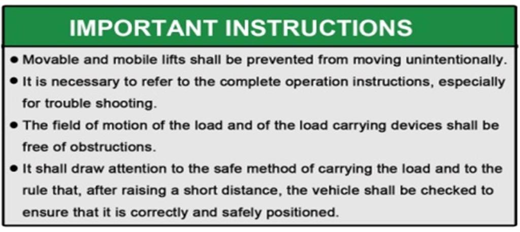
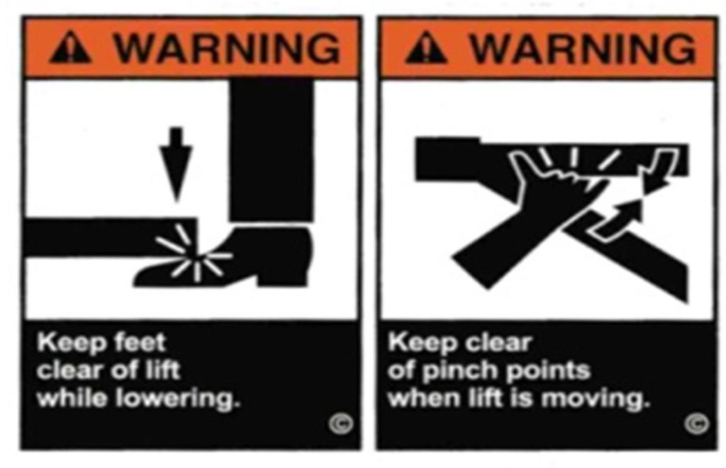
5 1.4 Caution and Warning Labels 5
6 2. Technical Specifications 2.1 Product Description The UTV lift bench is used for repairing and maintaining Side by Side Utility type Vehicles by 110VAC-60Hz, 1Ph power source incorporating the latest safety technologies. The is designed and manufactured for a max lifting capacity of 2,200 lbs. (1,000kg), and is fully capable for lifting most all UTV Side by Side Vehicles, while safely holding them in an elevated, locked height position. The electro-hydraulic UTV lift consists of a fixed structural scissor lift, hand held remote controller, exclusive retractable center ramp and side extensions with center drop access panels. 2.2 Product Specifications - Capacity: Lifting Height, Max: Height, Min: Width Overall: Length Overall: Platform Length: Platform Width: Power Supply: Lifting Time: Lowering Time: Gross Weight: 2,200 lbs.(1,000 kg) 47.2 (1,200 mm) 7 (180 mm) 65 (1651 mm) (2959 mm) - Fully Lowered 88.6 (2,250 mm) 65 (1270 mm) 110V, 60Hz, 1 Phase,18A 30 S 30 S 1,119 lbs. 6
7 Dimension Drawings 7
8 2.3 Hydraulic Schematic 1. OIL TANK 2. MESH 3. GEAR PUMP 4. MOTOR 5. ONE-WAY VALVE 6. MESH 7. SOLENOID VALVE 8. RESTRICTOR VALVE 9. RELIEF VALVE 10. RESTRICTOR VALVE 11. CYLINDER 12. PIPE 2.4 Circuit Diagram X P S B0 XP Power Cord w/ Plug 16A P E N L S B0 S B1 SB1 Up Switch Green Button 1 F U1 SB2 Down Switch Blue Button 1 S B1 SB3 Park Switch Black Button 1 K 3 M 0A F U KM AC Contactor 24VAC 1 TR Transformer 110VAC / 24VAC 1 FU Fuses 6 30 delay, 30A 2 FU1 Fuses 5 20 delay, 1A 2 M A Y 80L K M MA AC Motor 110VAC-1Ph, 60Hz,1.5HP 1 1.5H P 1 8A 1 A S B2 S B2 S B3 S B3 T R 4 0VA Y T Y V 1 ~ YT Electromagnet 24VDC, 520mA 1 YV Solenoid Valve 24VDC, 1A 1 8


9 3. Preparing and Installation 3.1 Site Selection The hydraulic UTV lift is designed only for indoor use. Application in a room with explosion hazard is not permitted. Setting in a wet place, a car wash bay for instance, is also not recommended. Make sure to check the desired location for possible obstructions such as a low ceiling, overhead lines, adequate working area, access ways, exits, etc. 3.2 Surface Condition The lift should be installed on level ground with a concrete surface free from as many defects as possible to prevent unit from tipping or rocking. Only use on a level concrete surface with a recommended minimum thickness of 4. DO NOT install on an asphalt type surface. Failure in accomplish the foundation requirement may cause the lift instability or personal injury. Installing on asphalt, soft clay floor or near the expansion gap is prohibited. 3.3 Necessary Tools Scissors, Screw Driver, Rubber Hammer, Adjustable Spanner Wrench, (Ext.) Snap Ring Pliers and Hex Key Set. Forklift & Soft Sling Straps also recommended. 3.4 Personal Protective Equipment Always wear proper protective equipment like proper clothing, shoes, gloves & safety glasses, etc. 3.5 Set-Up & Installation 1. Unpacking a. Carefully open crate and remove any loose parts from top of lift structure. b. Using a forklift (recommended) carefully remove lift from crate and place in the desired location (Fig.1). Ensure to check product and packing list to make certain all required parts are included and in good condition. Fig.1 9

 UP button. (Fig. 2) b.")

 PARKING button to secure lift in the locking")


10 2. Power Connection Before power connection is made, check your power supply outlet to ensure it s in accordance with the requirements of the lift. a. Connect lift s electrical plug to a 110V-60Hz, 1Ph, 20A power supply outlet. Protection against power surges shall be provided by the user. 3. Starting Up (No Load on Lift) a. Using the Remote Pendant Control, raise the platform to full height by pressing the (GREEN) UP button. (Fig. 2) b. Lower the lift to floor by pressing the (BLUE) DOWN button. c. With no load on lift, cycle up and down several times to get the air out of the hydraulic system. (Wait 2 minutes between cycles) d. After cycling lift, raise and secure at almost full height by pressing the (BLACK) PARKING button to secure lift in the locking position, as the electronic latches will automatically engage. (Securing lift at full to mid height is best for Assembly) Fig Assembly a. Attach or insert the front Wheel Stop Bar, Tie-Down Eyelets, Retractable Ramp & Stabilizer / Balance Bars - (Figs 3, 4 & 5) Fig. 3 Fig. 4 Fig. 5 b. Insert UTV Side Extension s Rods to outside of Platform and secure with Wing Bolts. Once Rods are secured to Platform, install the UTV Side Extensions and secure each end with Ring Clips - (Fig. 6) Note: Ensure to correctly install Side Extensions with holes for Wheel Stops positioned to front of lift. c. Insert UTV Wheel Strop Bars to the front of each Side Extension - (Fig. 6) d. Install UTV Pivot Ramps to the rear of each Side Extension using Pins & Circlips - (Fig. 7) Fig. 6 Fig. 7 10


11 5. Change the Tank Plug a. Remove black shipping Plug from reservoir tank and replace with the brass ventilating Plug - (Figs 8 & 9) Fig. 8 Fig. 9 The Lift is now ready for Operation 4. Operation Be sure to read and familiarize yourself with the Safety Instructions at the beginning of this manual. Be sure to wear gloves, protection glasses and all necessary personal protective equipment. Failure to follow Safety Instructions may result in property damage, personal injury or death. 4.1 Operating Instructions Be sure to read and familiarize yourself with the Safety Instructions at the beginning of this manual. Failure to follow Safety Instructions may result in property damage or personal injury. To avoid personal injury and/or property damage, permit only trained personnel to operate lift. ALWAYS use tie downs to secure vehicle to lift while in operation. 1. Lift Preparation: Lift must be fully lowered and area clear of all personnel before vehicles are placed on lift. 2. Loading Lift: Carefully push the vehicle on the fully lowered lift platform while keeping the vehicle centered and aligning the center of gravity of the equipment with the center of the lift platform. (For motorcycles, push forward until the front wheel touches the Wheel Stop or engages into the optional mounted Vise or Chock). Securing UTV - Engage the parking brake on the vehicle, if applicable. Secure UTV to lift using tie-down straps. Straps are recommended to be used to properly secure UTV to lift platform. Before attempting to lift any vehicles, be sure that vehicle is stable and properly secured on lift. 11
 UP button. c.")
12 3. To Raise Lift & Lock a. Push (GREEN) UP button on the remote hand held pendant controller. b. Raise vehicle to the desired height, then release the (GREEN) UP button. c. Push the (BLACK) PARKING button to lower the vehicle onto the locking position, as the locking latches will automatically engage. 4. (Emergency Button) The lift can be switched off immediately by pressing down the (RED) Emergency button on Remote Pendant Control. When any emergency situation comes, press down the emergency stop button immediately to stop the lift. When emergencies are resolved, twist & pull the red knob to release the emergency button to disengage the emergency stop mode. 5. To Lower Lift Check all danger points of the lift and be sure that there are no tools, objects or people in the working area (danger area) around the lift or under the lift before lowering. a. If the lift is already in the locked position (latches are engaged), press the (GREEN) UP button to raise the lift a short distance to disengage the latch mechanisms. b. Then press (BLUE) DOWN button on remote controller to lower lift to the floor, while observing the complete lowering process to check for any unexpected movement. c. Carefully remove the vehicle off of the lift platform, after lift is fully lowered to floor. Center Drop Panel usage: If side extension s Center Drop Panels are lowered (folded down), ensure to securely latch back into level position, prior to lowering lift. Failure to do so, could result in lift, vehicle & property damage. Remain clear of lift when lowering vehicle. Observe pinch point warning decals. If lift is not operating properly, DO NOT use until adjustment or repairs are made by qualified lift service personnel. DO NOT use the (BLACK) PARKING button instead of the (BLUE) DOWN button to lower. NEVER press the UP or DOWN button for a long time while the lift is not moving, or the control system will be damaged. Release button if you find the lift is not properly responding. Once finished with lift operation, engage the emergency button and unplug the lift is recommended. If any unsafe movement of the lift occurs, do not to operate the lift and call the local distributor for assistance. 12
13 5. Maintenance Instructions Contact your service provider for instructions before starting up if you are not completely familiar with lift s maintenance procedures. Only qualified personnel can perform maintenance on this equipment. Any failure in operation may cause personal injury and/or damage to lift. Daily: Wear necessary protective equipment before use, includes, but not limited, gloves and protection glasses, working suits and shoes. Always keep bolts tight. Check periodically. Always keep lift components clean. If oil leakage is observed, contact your service provider. Check safety latches for free movement and full engagement with lift are properly working Check hoses connections for leakage. Every Month: Lubricate locking latch shafts. Push latch handle several times for oil to penetrate joints. Lubricate the sliding pieces with heavy duty bearing grease. With lift lowered check the hydraulic fluid level. If necessary add oil as described in the Installation Instruction section of this manual Check platform latch synching: Latches should click at the same time. Check tightness of all bolts. Check the nuts for tightness every week for the first month, and every month afterwards. Every 6 Months: Check and clean the oil filter, if applies. Check the hydraulic oil for proper level with lift in down position. Refill reservoir tank with hydraulic oil if necessary with AW 32 or AW46 Non-Detergent Non-Foaming Anti-Wear Hydraulic Oil. If Lift stops short of full rise or chatters, contact your service provider. Replace all caution, warning or safety related decals on the lift if unable to read or missing. Reorder labels from service provider. Check all components for wear. 13


14 6. Exploded Views & Parts Lists Exploded Views (Lift Structure) 14


15 Exploded Views (Lift Structure) 15


16 Exploded Views (Lift Structure) Parts List - (Lift Structure) ITEM Tux P/N M-Ref P/N DESCRIPTION QTY 3 M-2200IEH-XR-003 JP E00 Rear Pivot Panel 1 4 M-2200IEH-XR-004 JP E00 Platform 1 5 M-2200IEH-XR-005 JP MC / UTV Wheel Stop 3 6 M-2200IEH-XR-006 JP Eye Bolt, M M-2200IEH-XR-007 JP E00 Rubber Pad 4 8 M-2200IEH-XR Lock Nut 6 9 M-2200IEH-XR Bolt, M6 x M-2200IEH-XR-010 JP Balance / Stabilizer Bar 1 11 M-2200IEH-XR-011 JP Sleeve 2 12 M-2200IEH-XR-012 JP Hinge Pin 2 13 M-2200IEH-XR Circlip, D M-2200IEH-XR Flat Washer, D M-2200IEH-XR-015 JP E00 Pin, Pivot Panel 1 16 M-2200IEH-XR-016 JP Spring 2 17 M-2200IEH-XR Screw, M6 x 12mm 4 18 M-2200IEH-XR-018 JP E00 Yellow Safety Strip, Ramp 1 27 M-2200IEH-XR Lock Nut, M5 1 16
17 29 M-2200IEH-XR-029 JP Pin # M-2200IEH-XR Bearing, D20 x D23 x 25mm 8 31 M-2200IEH-XR Circlip, D M-2200IEH-XR-032 JP Pin # M-2200IEH-XR Lock Nut, M M-2200IEH-XR Flat Washer, D M-2200IEH-XR-035 JP Pivot Bolt 2 36 M-2200IEH-XR Bearing, D25 x D28 x 25mm 8 37 M-2200IEH-XR-037 JP Down Roller 2 38 M-2200IEH-XR Flat Washer, D M-2200IEH-XR Circlip, D M-2200IEH-XR-040 JP Safety Latch (LH) M-2200IEH-XR JP Latch Frame (LH) M-2200IEH-XR Screw, M3 x 8mm M-2200IEH-XR JP Mount Plate M-2200IEH-XR Flat Washer, D M-2200IEH-XR Lock Washer, D M-2200IEH-XR Screw, M5 x 12mm M-2200IEH-XR MK Electromagnet M-2200IEH-XR Circlip, D M-2200IEH-XR JP Latch Pin M-2200IEH-XR JP Latch Cover M-2200IEH-XR Screw, M4 x 20mm M-2200IEH-XR JP Linkage Arm - Long M-2200IEH-XR Lock Nut, M M-2200IEH-XR JP Rocker Arm M-2200IEH-XR Screw, M4 x 12mm M-2200IEH-XR JP Linkage Arm - Short M-2200IEH-XR JP Latch 2 41 M-2200IEH-XR-041 JP Upper Roller 4 42 M-2200IEH-XR-042 JP Outer Scissor Frame 1 43 M-2200IEH-XR-043 JP Inner Scissor Frame 1 44 M-2200IEH-XR-044 JP Safety Latch (RH) M-2200IEH-XR JP Safety Latch Frame (RH) 1 45 M-2200IEH-XR-045 JP Cable Spring Cover # M-2200IEH-XR Screw, M6 x 6mm M-2200IEH-XR-047 JP Cable Bracket M-2200IEH-XR-048 MK Rubber Grommet 8 49 M-2200IEH-XR-049 JP Cable Spring Cover # M-2200IEH-XR MK Latch Cable # M-2200IEH-XR-050 JP Cable Spring Cover # M-2200IEH-XR MK Latch Cable # M-2200IEH-XR-051 JP Grease Zerk, M M-2200IEH-XR-052 JP Cylinder Pin - Long 1 53 M-2200IEH-XR-053 JP E00 Base Frame 1 54A M-2200IEH-XR-054A JP Cylinder (2200IEH-XR) M-2200IEH-XR JP Cylinder Body M-2200IEH-XR BZ Compensate Valve 1 17
18 54-3 M-2200IEH-XR Combined Washer, D M-2200IEH-XR JP Fitting Connector M-2200IEH-XR Lock Washer, D M-2200IEH-XR JP Piston M-2200IEH-XR JP Guide Ring 1 54A-8 M-2200IEH-XR-054A.8 JP Piston Bar M-2200IEH-XR O-Ring, D24.4 x D3.1mm M-2200IEH-XR Dust Ring, D M-2200IEH-XR JP Guide Ring, D40 x D45 x 15mm M-2200IEH-XR JP Guide Ring, D75 x D80 x 15mm M-2200IEH-XR Main Seal M-2200IEH-XR Screw, M12 x 20mm 1 54A-16 M-2200IEH-XR-054A Bearing, D25 x 20mm M-2200IEH-XR JP Cylinder Pin - Short 1 56 M-2200IEH-XR Screw, M6 x 8mm 4 57 M-2200IEH-XR-057 JP Power Unit Cover 1 58 M-2200IEH-XR-058 DBZ14S-00 Power Unit - 110V-1PH, 60Hz 1 59 M-2200IEH-XR-059 JP Power Unit Mount Plate 1 61 M-2200IEH-XR Lock Washer, D M-2200IEH-XR Bolt, M8 x 14mm 4 63 M-2200IEH-XR O-Ring, D10 x 2mm 1 64 M-2200IEH-XR-064 JP Hydraulic Hose 1 65 M-2200IEH-XR-065 DJ Cable Nut, M M-2200IEH-XR-066 MK010S-00 Control Box 1 67 M-2200IEH-XR-067 MK Power Cord w/ Ground, 110V 1 68 M-2200IEH-XR-068 MK Remote Pendant Control 1 71 M-2200IEH-XR-071 JP Cable Clamp, 5P M-2200IEH-XR Screw, M5 x 14mm 1 73 M-2200IEH-XR-073 JP E00 Pull Bar 2 74 M-2200IEH-XR-074 JP Limit Roller 2 75 M-2200IEH-XR-075 JP Sleeve 2 76 M-2200IEH-XR-076 JP Roller Pin 2 77 M-2200IEH-XR-077 JP Roller Plate 2 78 M-2200IEH-XR-078 JP E00 Retractable Ramp 1 79 M-2200IEH-XR Lock Nut, M M-2200IEH-XR-080 JP Nylon Ramp Wheel 2 81 M-2200IEH-XR Circlip, D M-2200IEH-XR-082 JP E00 Ramp Roller 2 83 M-2200IEH-XR-083 JP E00 Roller Pivot Pin 2 86 M-2200IEH-XR-086 JP Lock Plate 1 87 M-2200IEH-XR Screw, M6 x 14mm 2 P1 -P1 JP PB7 Pivot Ramp, UTV-XR 2 P2 -P2 JP Ring Clip 4 P3 -P3 JP PB2 Support Rod, UTV 4 P4 -P4 JP PB4 Latch Pin Bracket 2 P5 -P Lock Washer, D6 4 P6 -P Flat Washer, D6 4 P7 -P Screw, M6 x 12mm 4 18
19 P8 -P8 JP PB4 Latch Pin, Drop Panel 2 P9 -P9 JP PB4 Center Drop Panel 2 P10 -P Circlip, D12 8 P11 -P11 JP Hinge Pin 4 P12 -P Wing Bolt, M12 x 16mm 8 P13 -P13 JP PB7 Side Extension Panel, UTV-XR (LH) 1 P13-1 -P13.1 JP PB7 Side Extension Panel, UTV-XR (RH) 1 P14 -P14 JP PB7 Ramp Pivot Pin, UTV-XR 2 P15 -P15 JP Nylon Ramp Wheel 4 Exploded View (Power Unit)
20 Parts List (Power Unit) ITEM Tux P/N M-Ref P/N DESCRIPTION QTY 1 M-2200IEH-PU-001 BZ B00 Motor 110VAC-1Ph 60Hz 1 2 M-2200IEH-PU-002 BZ Cap Nut-A 1 3 M-2200IEH-PU-003 BZ Cap Nut-B 1 4 M-2200IEH-PU O-Ring 2 5 M-2200IEH-PU-005 BZ Spring 1 6 M-2200IEH-PU-006 BZ Ball Seat 1 7 M-2200IEH-PU Ball 2 8 M-2200IEH-PU-008 BZ Ball Seat 1 9 M-2200IEH-PU-009 BZ Spring 1 10 M-2200IEH-PU-010 BZ Threaded Pin 1 11 M-2200IEH-PU O-Ring 1 12 M-2200IEH-PU-012 BZ Special Washer 1 13 M-2200IEH-PU-013 BZ Lock Nut 1 14 M-2200IEH-PU-014 BZ Protective Cap 1 15 M-2200IEH-PU-015 BZ Return Pipe 1 16 M-2200IEH-PU O-Ring 1 17 M-2200IEH-PU O-Ring 1 18 M-2200IEH-PU O-Ring 1 19 M-2200IEH-PU-019 BZ B00 Gear Pump 1 20 M-2200IEH-PU Bolt 2 21 M-2200IEH-PU Self-Lock Nut 4 22 M-2200IEH-PU-022 BZ Tank 1 23 M-2200IEH-PU-023 QY Vent Cover 1 24 M-2200IEH-PU-024 QY Combined Washer 1 25 M-2200IEH-PU-025 BZ Pick-Up Tube 1 26 M-2200IEH-PU-026 BZ Strainer 1 27 M-2200IEH-PU-027 BZ Joint 1 28 M-2200IEH-PU-028 BZ Valve Cable 1 29 M-2200IEH-PU-029 BZ Electromagnetic Valve 1 30 M-2200IEH-PU O-Ring 1 31 M-2200IEH-PU-031 BZ Filter Screen 1 32 M-2200IEH-PU O-Ring 1 33 M-2200IEH-PU Circlip 1 34 M-2200IEH-PU Screw 4 35 M-2200IEH-PU-035 BZ Valve Block 1 36 M-2200IEH-PU Ball 2 37 M-2200IEH-PU-037 BZ Threaded Pin 2 38 M-2200IEH-PU-038 BZ Capacitor Cover 1 39 M-2200IEH-PU Screw 2 40 M-2200IEH-PU Flat Washer 2 41 M-2200IEH-PU-041 BZ B00 Start Capacitor 1 42 M-2200IEH-PU-042 BZ Cable Nut 1 20
21 Exploded View (Control Box) Parts List (Control Box) 6 ITEM Tux P/N M-Ref P/N DESCRIPTION QTY 1 M-2200IEH-CB-001 MK Control Box Shell 1 2 M-2200IEH-CB-002 JK Cable Nut 2 3 M-2200IEH-CB-003 DJ Cable Nut 3 4 M-2200IEH-CB-004 MK Mount Plate 1 5 M-2200IEH-CB-005 MK B00 Transformer 1 6 M-2200IEH-CB-006 JK Self-Tapping Screw 6 7 M-2200IEH-CB-007 DK Fixing Board 2 8 M-2200IEH-CB-008 DK Wiring Terminal 10 9 M-2200IEH-CB Flat Washer 4 10 M-2200IEH-CB-010 JK Self-Tapping Screw 8 11 M-2200IEH-CB-011 MK Connection Rail 1 12 M-2200IEH-CB-012 JK Fuse, 1A 2 13 M-2200IEH-CB-013 MK B00 Fuse, 30A 2 14 M-2200IEH-CB-014 DK Fuse Seat 1 15 M-2200IEH-CB-015 JK Fuse Seat Board 1 16 M-2200IEH-CB-016 JK Fuse Seat 2 17 M-2200IEH-CB Tapping Screw 2 18 M-2200IEH-CB-018 MK Bridge Rectifier 1 19 M-2200IEH-CB-019 JK Self-Tapping Screw 2 20 M-2200IEH-CB-020 JK Contactor 1 21 M-2200IEH-CB-021 JK Cable Ring 2 22 M-2200IEH-CB-022 JK Ground End 1 23 M-2200IEH-CB-023 JK01-JD Ground Decal 1 24 M-2200IEH-CB Flat Washer 2 25 M-2200IEH-CB Self-Tapping Screw 2 21
22 7. Troubleshooting Guide A. Problem Motor does not run. Possible cause: Solution: 1. Blown fuse or circuit breaker. 1. Replace fuse or reset circuit breaker. 2. Incorrect voltage to motor. 2. Supply correct voltage to motor. 3. Bad wiring connections. 3. Repair and insulate all connections. 4. Motor up switch burned out. 4. Replace switch. 5. Overhead limit switch burned out. 5. Replace switch. 6. Motor windings burned out. 6. Replace motor. B. Problem Motor runs but lift will not raise. Possible cause: Solution: 1. Open lowering valve. 2. Pump sucking air. 3. Suction stub off pump. 4. Low oil level. 1. Repair or replace lowering valve. 2. Tighten all suction line fittings. 3. Replace suction stub. 4. Fill tank with SAE-10, AW 32 or equivalent. C. Problem Lift will raise up only without load. Possible cause: Solution: 1. Motor running on low voltage. 2. Debris in lowering valve. 3. Improper relief valve adjustment. 4. Overloading. 1. Supply correct voltage to motor. 2. Clean lowering valve. 3. Replace relief valve cartridge. 4. Check or balance the vehicle weight on lift. D. Problem Lift slowly settles down. Possible cause: Solution: 1. Debris in check valve seat. 2. Debris in lowering valve seat. 3. External oil leaks. 1. Clean check valve. 2. Clean lowering valve. 3. Repair external leaks. E. Problem Slow lifting speed or oil blowing out breather cap Possible cause: Solution: 1. Air mixed with oil. 2. Air mixed with oil suction. 3. Oil over filled. 4. Debris in check valve seat. 5. Debris in lowering valve seat. 1. Change oil to non-foaming SAE-10, AW 32 or equivalent. 2. Tighten all suction line fittings. 3. Only fill or add oil to tank when lift is fully lowered. 4. Clean check valve. 5. Clean lowering valve. H. Problem Locking latches do not engage. Possible cause: 1. Latches and/or shafts rusted. 2. Release the lock without lifting. 3. Latch cable broken or bad connection. Solution: 1. Remove covers, oil latch mechanism. (Depress latch release handle several times to allow oil to coat shaft.) 2. Raise lift a short distance first. 3. Check cable connection or replace. 22
23 Structural Warranty: LIMITED WARRANTY The following parts and structural components carry a five year warranty: Columns Arms Uprights Swivel Pins Legs Carriages Overhead Beam Tracks Cross Rails Top Rail Beam Limited One-Year Warranty: Tuxedo Distributors, LLC (ideal) offers a limited one-year warranty to the original purchaser of Lifts and Wheel Service equipment in the United States and Canada. Tuxedo will replace, without charge, any part found defective in materials or workmanship under normal use, for a period of one year after purchase. The purchaser is responsible for all shipping charges. This warranty does not apply to equipment that has been improperly installed or altered or that has not been operated or maintained according to specifications. Other Limitations: This warranty does not cover: 1. Parts needed for normal maintenance 2. Wear parts, including but not limited to cables, slider blocks, chains, rubber pads and pulleys 3. Replacement of lift and tire changer cylinders after the first 30 days. A seal kit and installation instructions will be sent for repairs thereafter. 4. On-site labor Upon receipt, the customer must visually inspect the equipment for any potential freight damage before signing clear on the shipping receipt. Freight damage is not considered a warranty issue and therefore must be noted for any potential recovery with the shipping company. The customer is required to notify Tuxedo of any missing parts within 72 hours. Timely notification must be received to be covered under warranty. Tuxedo will replace any defective part under warranty at no charge as soon as such parts become available from the manufacturer. No guarantee is given as to the immediate availability of replacement parts. Tuxedo reserves the right to make improvements and/or design changes to its lifts without any obligation to previously sold, assembled or fabricated equipment. There is no other express warranty on the Tuxedo lifts and this warranty is exclusive of and in lieu of all other warranties, expressed or implied, including all warranties of merchantability and fitness for a particular purpose. To the fullest extent allowed by law, Tuxedo shall not be liable for loss of use, cost of cover, lost profits, inconvenience, lost time, commercial loss or other incidental or consequential damages. This Limited Warranty is granted to the original purchaser only and is not transferable or assignable. Some states do not allow exclusion or limitation of consequential damages or how long an implied warranty lasts, so the above limitations and exclusions may not apply. This warranty gives you specific legal rights and you may have other rights, which may vary from state to state E Hwy 67, Alvarado, TX Ph / Fax
MR6K lb Capacity Portable Mid-Rise Scissor Lift. Operation Manual
 MR6K-38 6000 lb Capacity Portable Mid-Rise Scissor Lift Operation Manual 6,000 LB. PORTABLE MID-RISE FRAME LIFT A comfortable 38 working height, twin cylinders and double safety locks make this portable
1300 lb Capacity Trike Lift
 M-1300C-TRIKE 1300 lb Capacity Trike Lift USER S MANUAL TRIKE MOTORCYCLE LIFT An extra wide platform designed especially for three-wheel motorcycles. M-1300-TRIKE Trike Motorcycle Lift SPECIFICATIONS:
SCISSOR LIFT Model MR6K-38 /161108A 6,000lb Capacity Operation Manual
 SCISSOR LIFT Model MR6K-38 /161108A 6,000lb Capacity Operation Manual (Version A) 2009. Apr. CONTENT 1. Safety Note, Caution and Warning Important Information Safety Instructions 2. Technical Manual Product
MOTORCYCLE LIFTS SPECIFICATIONS: M-1000C M-1500C-HR
 M1000C 1000l bcapaci t y Mot or cycl eli f t MOTORCYCLE LIFTS These lift tables are ideal for making repairs to motorcycles, snowmobiles, ATVs, jet skis, etc. Choose from a range of accessories to customize
ASSEMBLY & OPERATION INSTRUCTION MANUAL
 LR-26-PAD 6000 lb Capacity Low-Rise Pad Lift ASSEMBLY & OPERATION INSTRUCTION MANUAL 6,000 LB. LOW-RISE PAD LIFT Easy frame lifting on padded runways. Great for wheel and brake work, tire and wheel changing
MSC-6KLP Low Profile Mobile Single Column Lift. 6,000 lb. Capacity (1,500 lbs. Max Capacity per Arm) Installation & Operation Manual
 Installation & Operation Manual") Low Profile Mobile Single Column Lift 6,000 lb. Capacity (1,500 lbs. Max Capacity per Arm) Installation & Operation Manual INDEX PREFACE-------------------------------------------------------------------------------
Low Profile Mobile Single Column Lift 6,000 lb. Capacity (1,500 lbs. Max Capacity per Arm) Installation & Operation Manual INDEX PREFACE-------------------------------------------------------------------------------
ATD2P11BS. Two-Post Clear Floor Bi-Symmetric Automotive Lift. Installation & Operation Manual. 11,000 lbs. Capacity. (2,750 lbs.
 Two-Post Clear Floor Bi-Symmetric Automotive Lift 11,000 lbs. Capacity (2,750 lbs. Max per Arm) Installation & Operation Manual 1. Safety Information 1.1 Note, Caution and Warning 1.2 Important Information
MR6K-48X. Mid-Rise Scissor Lift ASSEMBLY & OPERATION INSTRUCTION MANUAL. 6,000 lbs.
 MR6K-48X Mid-Rise Scissor Lift 6,000 lbs. ASSEMBLY & OPERATION INSTRUCTION MANUAL November 2014 Important! Be sure to read the operating instructions before operating your lift! Getting Ready Make sure
ASSEMBLY & OPERATION INSTRUCTION MANUAL
 Sliding Bridge Jack 3,500 lbs. Capacity ASSEMBLY & OPERATION INSTRUCTION MANUAL TABLE OF CONTENTS Specifications... 2 Description & Features... 3 Installation Instructions... 4 Safety Instructions... 4
Read this entire manual before operation begins.
 Read this entire manual before operation begins. Record below the following information which is located on the serial number data plate. Serial No. Model No. Date of Installation Contents Specifications.............
2-Post Lift Operations and Maintenance Manual
 2-Post Lift Operations and Maintenance Manual Table Of Contents Safety Instructions... 2 Owner/Employer Responsibilities / Operating Conditions... 3 Operating Instructions... 4 Maintenance Instructions...
MID RISE. INSTALLATION and OPERATION MANUAL MODEL 6000A // 6000E 6,000 LB. CAPACITY. READ and SAVE THIS INSTRUCTION MANUAL
 INSTALLATION and OPERATION MANUAL MID RISE MODEL 6000A // 6000E 6,000 LB. CAPACITY READ and SAVE THIS INSTRUCTION MANUAL AUGUST 2005 6-0944 6500 Millcreek Drive Mississauga, Ontario Canada L5N 2W6 1-800-268-7959
Read this entire manual before operation begins.
 Read this entire manual before operation begins. Record below the following information which is located on the serial number data plate. Serial No. Model No. Date of Installation Contents Specifications.............
Read this entire manual before operation begins.
 Read this entire manual before operation begins. Record below the following information which is located on the serial number data plate. Serial No. Model No. Date of Installation Contents Specifications.............
Read this entire manual before operation begins.
 Read this entire manual before operation begins. Record below the following information which is located on the serial number data plate. Serial No. Model No. Date of Installation Contents Specifications.............
Read this entire manual before operation begins.
 Read this entire manual before operation begins. Record below the following information which is located on the serial number data plate. Serial No. Model No. Date of Installation Contents Specifications.............
INSTALLATION & OPERATION MANUAL
 Two-Post Clear Floor Lift (Asymmetric) 9,000 lbs. Capacity (2,250 lbs. Max per Arm) INSTALLATION & OPERATION MANUAL IMPORTANT NOTES READ THE INSTALLATION AND OPERATION MANUAL IN ITS ENTIRETY BEFORE ATTEMPTING
ATDTCHD & ATDTCHDPA Tire Changer Installation and Operation Manual
 ATDTCHD & ATDTCHDPA Tire Changer Installation and Operation Manual Features: Swing Arm Design Handles Tires up to 47" and Rim widths up to 15" Press Arm for Low Profile Tires Four Pneumatic Clamps and
Read this entire manual before operation begins.
 Read this entire manual before operation begins. Record below the following information which is located on the serial number data plate. Serial No. Model No. Date of Installation Contents Specifications.............
GLO-8000 SERIES (GLO-8000 & GLO-8000XLT)
") GLO-8000 SERIES (GLO-8000 & GLO-8000XLT) 8,000 LBS. CAPACITY FOUR-POST STORAGE LIFT INSTALLATION & OPERATION MANUAL SERIAL NUMBER: INSTALLATION DATE: EAGLE EQUIPMENT 1-800-336-2776 REV2011 03.0 BD SHIPPING
GLO-8000 SERIES (GLO-8000 & GLO-8000XLT) 8,000 LBS. CAPACITY FOUR-POST STORAGE LIFT INSTALLATION & OPERATION MANUAL SERIAL NUMBER: INSTALLATION DATE: EAGLE EQUIPMENT 1-800-336-2776 REV2011 03.0 BD SHIPPING
ATTENTION. 1. Do not attempt to use the power unit to extend your cylinder. This must be done manually.
 NSS8XLT Installation Manual ATTENTION By following the instructions in this manual you can save yourself much time, frustration and money. The installation of your lift will take 4-5 hours. Do not rush.
MIDRISE MODEL SM60F_1 // SM60F_A 6,500 LB. CAPACITY
 INSTALLATION and OPERATION MANUAL READ THIS INSTRUCTION MANUAL THOROUGHLY BEFORE INSTALLING, OPERATING, SERVICING OR MAINTAINING THE LIFT. SAVE THIS MANUAL. NOV 2007 REV.B MIDRISE MODEL SM60F_1 // SM60F_A
Atlas PV-9WP Addendum
 Atlas PV-9WP Addendum 9,000 lb. Capacity Two-Post Overhead Lift The Atlas PV-9WP above ground hoist is 6 inches wider than the Atlas PV-9P, giving it an overall width of 141 (11 9 ) and a drive thru width
Hydraulic Wheel Dolly
 Hydraulic Wheel Dolly Operating Instructions & Parts Manual Model Number HW93766 Capacity 3/4 Ton Made in the U.S.A. This is the safety alert symbol. It is used to alert you to potential personal injury
Hydraulic Transmission Jacks
 Hydraulic Transmission Jacks Operating Instructions & Parts Manual Model Number Atd-7435 Atd-7436 Atd-7437 Capacity 1100 Lb. 2000 Lb. 3000 Lb. Model Atd-7435 Model Atd-7436 Model Atd-7437 Atd Tools Inc.
Index. 1. Important safety instructions Overview of the lift Installation instructions Operation instructions 8-9
 2 Index 1. Important safety instructions 4-5 1.1 Safety Warnings 1.2 Qualified personnel 1.3 Safety 1.4 Warning signs 2. Overview of the lift 6 2.1 General descriptions 2.2 Technical data 2.3 Construction
BLAZER 9000 LUBE LIFT OPERATOR AND PARTS MANUAL
 BLAZER 9000 LUBE LIFT OPERATOR AND PARTS MANUAL Blazer 9000 Lube Lift Operator s Manual Note: Instructions must be read thoroughly before installing, operating, or maintaining the lift. Devon Lube Center
TWO POST LIFT INSTALLATION AND OWNERS MANUAL
 TWO POST LIFT INSTALLATION AND OWNERS MANUAL DP15, DP15-2 Capacity 15,000 lbs. 1. TABLE OF CONTENTS 2. Important Information.. 2 3. Section 1 Owner s Manual Safety Instructions... 3 Monthly Maintenance...
MODEL QMR6 PORTABLE MID-RISE LIFT 6,000 lb Capacity 1500 lb Per Arm INSTALLATION, OPERATION AND MAINTENANCE MANUAL
 MODEL QMR6 PORTABLE MID-RISE LIFT 6,000 lb Capacity 1500 lb Per Arm INSTALLATION, OPERATION AND MAINTENANCE MANUAL IMPORTANT!!! READ THIS MANUAL COMPLETELY BEFORE INSTALLING OR OPERATING THE LIFT 200 CABEL
24 VOLT AUTOMATIC BATTERY CHARGER PART NO
 24 VOLT AUTOMATIC BATTERY CHARGER PART NO. 957732 AC Input: DC Output: Battery Type: Specifications 230 volts, 50 hertz, 3.5 amps, single-phase 24 volts, 20 amps initially tapering to 6 amps 24 volt, 12
HEAVY DUTY TROLLEY JACK. Operation Manual
 HEAVY DUTY TROLLEY JACK 4T Operation Manual Make sure to read and fully understand the instruction manual before using this product and keep the manual properly 1 General Description Product Description
GLO-7000 SERIES (GLO-7000 & GLO-7000XLT)
") GLO-7000 SERIES (GLO-7000 & GLO-7000XLT) 7,000 LBS. CAPACITY FOUR-POST STORAGE LIFT (BLUE) INSTALLATION & OPERATION MANUAL SERIAL NUMBER: INSTALLATION DATE: EAGLE EQUIPMENT 1-800-336-2776 (STANDARD) SHIPPING
GLO-7000 SERIES (GLO-7000 & GLO-7000XLT) 7,000 LBS. CAPACITY FOUR-POST STORAGE LIFT (BLUE) INSTALLATION & OPERATION MANUAL SERIAL NUMBER: INSTALLATION DATE: EAGLE EQUIPMENT 1-800-336-2776 (STANDARD) SHIPPING
ATO7 (100 Series Lifts)
") O PE ATO7 (100 Series Lifts) Capacity 7000 lbs. (3181 kg) 1750 lbs. (795.25 kg) per arm R A TI O N & M AI N TE N A N N CE Table Of Contents Safety Instructions... 2 Owner/Employer Responsibilities / Operating
O PE ATO7 (100 Series Lifts) Capacity 7000 lbs. (3181 kg) 1750 lbs. (795.25 kg) per arm R A TI O N & M AI N TE N A N N CE Table Of Contents Safety Instructions... 2 Owner/Employer Responsibilities / Operating
LESTRONIC II BATTERY CHARGER MODEL 19740
 *01679* LESTRONIC II BATTERY CHARGER MODEL 19740 PLEASE SAVE THESE IMPORTANT SAFETY AND OPERATING INSTRUCTIONS For correct operation of the equipment, it is important to read and be familiar with this
Heavy Duty Engine Cranes
 Heavy Duty Engine Cranes Operating Instructions & Parts Manual Model Number Atd-7484 Atd-7485 (Foldable Legs) Capacity 2 Ton 2 Ton Model Atd-7484 Model Atd-7485 Atd Tools Inc. 160 Enterprise Drive, Wentzville,
FP7K&FP7KXLT REV A
 FP7K&FP7KXLT 7000l bcapaci t y Ser vi ce/ St or ageli f t I ns t a l l a t i o n& Ope r a t i o nma nua l REV A-080113 7,000 LB./9,000 LB. STORAGE /SERVICE LIFT 7,000 lb./ 9,000 lb.capacity and large
GLO-502/530 (RIM CLAMP TIRE CHANGER)
") GLO-502/530 (RIM CLAMP TIRE CHANGER) OPERATION MANUAL DATE INSTALLED: SERIAL # MANUFACTURING DATE: (EAGLE - GLOBAL : NHT) TABLE OF CONTENT INTRODUCTION -------------------------------------------------------------------------------2
GLO-502/530 (RIM CLAMP TIRE CHANGER) OPERATION MANUAL DATE INSTALLED: SERIAL # MANUFACTURING DATE: (EAGLE - GLOBAL : NHT) TABLE OF CONTENT INTRODUCTION -------------------------------------------------------------------------------2
CONTENTS. Product Features and Specifications Installation Requirement Installation Exploded View Operation Instruction...
 1 CONTENTS Product Features and Specifications... 3 Installation Requirement... 5 Installation... 6 Exploded View... 20 Test... 22 Operation Instruction... 25 Maintenance... 26 Trouble Shooting... 27 Parts
CONTENTS. Product Features and Specifications Installation Requirement Steps of Installation 4. Exploded View Test Run...
 CONTENTS Product Features and Specifications... 1 Installation Requirement... 3 Steps of Installation 4 Exploded View... 14 Test Run... 16 Operation Instruction... 19 Maintenance... 20 Trouble Shooting...
Low Profile Service Jack Jack Stand Combo
 Low Profile Service Jack Jack Stand Combo Jack Stands Low Profile Service Jack U.S. Patent No. 6,199,379! This is the safety alert symbol. It is used to alert you to potential personal injury hazards.
Hydraulic Clutch Jack
 Hydraulic Clutch Jack Operating Instructions & Parts Manual Model Number Atd-7404 Capacity 500 Lb. Atd Tools Inc. 160 Enterprise Drive, Wentzville MO 63385 Printed in China ATD7404-M0 05/07 Save these
Strut Spring Compressor
 Strut Spring Compressor Operating Instruction & Parts Manual Model Number Atd-7553 Model Atd-7553 Atd Tools Inc. 114 I-70 Trade Center Drive, St. Peters, MO 63376 Printed in Taiwan Save these instructions.
LESTRONIC II BATTERY CHARGER BUILT-IN OR PORTABLE CHARGERS
 LESTRONIC II BATTERY CHARGER BUILT-IN OR PORTABLE CHARGERS PLEASE SAVE THESE IMPORTANT SAFETY AND OPERATING INSTRUCTIONS For correct operation of the equipment, it is important to read and be familiar
Floor Plate Style Lift And Overhead Beam Style Lift. Two Post Lift
 Floor Plate Style Lift And Overhead Beam Style Lift 9,000 POUND Two Post Lift ASSEMBLY & OPERATION INSTRUCTION TABLE OF CONTENTS Important Note Page 3 Definition Page 4 Preparation and General Information
Product Information Responsibilities of Owners Safety Instructions Warning Labels Installation Instructions...
 Table of Contents Product Information... 2 Responsibilities of Owners... 3 Safety Instructions... 4 Warning Labels... 5 Installation Instructions... 6 Electrical Installation... 7 Load Capacity... 8 Daily
Telescopic Transmission Jacks
 Telescopic Transmission Jacks Operating Instructions & Parts Manual Model Number BH7051 BH7055 (Air/Manual) Capacity 1/2 Ton 1/2 Ton SFA Companies 2006 10939 N. Pomona Ave. Kansas City, MO 64153 816-891-6390
SPOA10NB, SPOA10, SPO10 ( Series Lifts) SPOA7, SPOA9, SPO9 (500 Series Lifts)
 SPOA7, SPOA9, SPO9 (500 Series Lifts)") O PE SPOA10NB, SPOA10, SPO10 (200-700 Series Lifts) SPOA7, SPOA9, SPO9 (500 Series Lifts) SPOA7 Capacity 7,000 lbs. SPOA9, SPO9 Capacity 9,000 lbs. SPOA10NB, SPOA10, SPO10 Capacity 10,000 lbs. R A TI O
O PE SPOA10NB, SPOA10, SPO10 (200-700 Series Lifts) SPOA7, SPOA9, SPO9 (500 Series Lifts) SPOA7 Capacity 7,000 lbs. SPOA9, SPO9 Capacity 9,000 lbs. SPOA10NB, SPOA10, SPO10 Capacity 10,000 lbs. R A TI O
OPERATORS MANUAL/INSTRUCTIONS/PARTS & SERVICE FOR MANUAL & ELECTRIC
 OPERATORS MANUAL/INSTRUCTIONS/PARTS & SERVICE FOR MANUAL & ELECTRIC TABLE OF CONTENTS SAFETY DELIVERY INSPECTION OPERATION 4 MAINTENANCE 5 TROUBLE SHOOTING 5 PARTS 6-15 Frame Scissor Assembly 6-7 Thrust
Air Actuated Hydraulic Bottle Jacks
 Air Actuated Hydraulic Bottle Jacks Operating Instructions & Parts Manual Model Number Atd-7412 Atd-7420 Capacity 12 Ton 20 Ton Atd Tools Inc. 160 Enterprise Drive, Wentzville MO 63385 Printed in China
EZ LINER EXPRESS USERS MANUAL
 EZ LINER EXPRESS 2013 Vehicle Service Group CHIEF'S LIMITED ONE-YEAR WARRANTY & LIABILITY Chief Automotive Technologies warrants for one year from date of installation and/or purchase any components of
Color Logo use on white background only. Red: Blue: PMS Black Logo use on white background only
 Color Logo use on white background only Red: 0-0-0-0 Blue: PMS 29 0-6-0-0 Owners Manual LH400 (Lift Hoist 400) Platform Hoist This Hoist is Equipped with a Quick Change Cable Drum Effective: /18/2011 Black
TWO POST LIFT INSTALLATION AND OWNERS MANUAL. January 2008 rev. E I MAN
 TWO POST LIFT INSTALLATION AND OWNERS MANUAL DP15, DP15-2 Capacity 15,000 lbs. January 2008 rev. E 1. TABLE OF CONTENTS 2. Important Information.. 2 3. Section 1 Owner s Manual Safety Instructions... 3
Read this entire manual before operation begins.
 Rev. 12/12/2017 Read this entire manual before operation begins. Record below the following information which is located on the serial number data plate. Serial No. Model No. Date of Installation Contents
SL210i/SL212i/SL19i. Table Of Contents
 SL210i/SL212i/SL19i (700 Series) SL19i Capacity 9,000 lbs. SL210i Fixed Pad Capacity 9,000 lbs. SL210i Capacity 10,000 lbs. SL212i Capacity 12,000 lbs. Table Of Contents Owner/Employer Responsibilities...
Hydraulic Transmission Jack
 Hydraulic Transmission Jack Operating Instructions & Parts Manual Model Number HW93716 Capacity 1/2 Ton Made in North America! This is the safety alert symbol. It is used to alert you to potential personal
Models PR-12F PR-12C PR-15C SURFACE MOUNTED TWO-POST LIFTS INSTALLATION AND OPERATION MANUAL
 Forward this manual to all operators. Failure to operate this equipment as directed may cause injury. INSTALLATION AND OPERATION MANUAL SURFACE MOUNTED TWO-POST LIFTS Models PR-12F PR-12C PR-15C Keep this
TXJ0500/RR500 1,000-lbs. Truck Bed Roller Dolly
 OWNER S MANUAL TXJ0500/RR500 1,000-lbs. Truck Bed Roller Dolly WARNING: Questions, problems, missing parts? Before returning to your retailer, call our customer service department at 1-888-448-6746, 8
Product Information Responsibilities of Owners Safety Instructions Warning Labels Installation Instructions...
 Table of Contents Product Information... 2 Responsibilities of Owners... 3 Safety Instructions... 4 Warning Labels... 5 Installation Instructions... 6 Electrical Installation... 7 Load Capacity... 8 Daily
MODEL 7400 STRUT SPRING COMPRESSOR
 MODEL 7400 STRUT SPRING COMPRESSOR Installation, Operation & Repair Parts Information Branick Industries, Inc. 4245 Main Avenue P.O. Box 1937 Fargo, North Dakota 58103 REV112712 P/N: 81-0103A TABLE OF
Lumina 28 Traction Drive Model: Battery Burnisher M28036TDQP OPERATION SERVICE PARTS CARE
 Lumina 28 Traction Drive Model: Battery Burnisher M28036TDQP OPERATION SERVICE PARTS CARE Table of Contents IMPORTANT SAFETY INSTRUCTIONS...1 OPERATING INSTRUCTIONS...2 INSPECTION...2 ELECTRICAL...2 BATTERIES...2
Hydraulic Transmission Jack, Telescopic
 Operating Instructions & Parts Manual Hydraulic Transmission Jack, Telescopic Model 4000 400 (Air Operated) Capacity 000 lbs. 000 lbs. Model 4000 Model 400 U.S. Patent No. 6,02,377! This is the safety
1000 lb. Adjustable Gantry Crane
 1000 lb. Adjustable Gantry Crane Owner s Manual WARNING: Read carefully and understand all ASSEMBLY AND OPERATION INSTRUCTIONS before operating. Failure to follow the safety rules and other basic safety
Low Profile Service Jack
 Low Profile Service Jack Model GMG29031 Capacity 3 Ton U.S. Patent No. 6,199,379! This is the safety alert symbol. It is used to alert you to potential personal injury hazards. Obey all safety messages
Parallel Lift Rack MODEL RM
 Form 4401T, 09-03 Supersedes Form 4401T, 10-00 OPERATION INSTRUCTIONS Parallel Lift Rack MODEL RM Copyright 1998-2003 Hunter Engineering Company Contents 1. For Your Safety... 1 1.1 Warning/Instruction
MOTORIZED FOLDING CAMPER WINCH
 OWNER'S MANUAL MOTORIZED FOLDING CAMPER WINCH With 1200lb Lift Capacity The 12 Volt Motorized Folding Camper Winch is used to raise and lower folding campers with the touch of the switch, eliminating hand
MODEL HD-BTC. Installation, Operation & Repair Parts Information REV041416
 MODEL HD-BTC Installation, Operation & Repair Parts Information REV041416 TABLE OF CONTENTS SAFETY INSTRUCTIONS 1 DEFINITIONS 1 SPECIFICATIONS 2 INSTALLATION INSTRUCTIONS 2 OPERATING INSTRUCTIONS 2 MAINTENANCE
OPERATOR S MANUAL. 20-bu 3-Point Hitch Material Collection System. LP65048 Supplier ST /07/2017 English. North American Edition Printed in USA
 OPERATOR S MANUAL 20-bu 3-Point Hitch Material Collection System LP65048 Supplier ST48289 11/07/2017 English North American Edition Printed in USA Introduction Using Your Operator s Manual Read this entire
TT-12 OWNERS MANUAL/PARTS LIST
 TOPLIFTER Tailgates By THIEMAN TT-12 OWNERS MANUAL/PARTS LIST SHOWN WITH OPTIONAL 2 PC. ALUMINUM PLATFORM! IMPORTANT! KEEP IN VEHICLE! PLEASE READ AND UNDERSTAND THE CONTENTS OF THIS MANUAL BEFORE OPERATING
Motorcycle Lift 1,000 lbs. capacity Installation, Safety, Operation, Maintenance
 Motorcycle Lift 1,000 lbs. capacity Installation, Safety, Operation, Maintenance Entire contents 2008 by RL Consolidated, Inc. All rights reserved. 994358 CO7297 Rev. F 12/17/2008 Inspection upon receipt
TP12KC-DX. Two Post Clear Floor. Automotive Lift. 12,000 lb. Capacity. (3,000 lbs. Max Capacity per Arm) Installation & Operation Manual
 Installation & Operation Manual") Two Post Clear Floor Automotive Lift 12,000 lb. Capacity (3,000 lbs. Max Capacity per Arm) Installation & Operation Manual IMPORTANT!! READ MANUAL THOROUGHLY BEFORE INSTALLING, OPERATING, SERVICING OR
Two Post Clear Floor Automotive Lift 12,000 lb. Capacity (3,000 lbs. Max Capacity per Arm) Installation & Operation Manual IMPORTANT!! READ MANUAL THOROUGHLY BEFORE INSTALLING, OPERATING, SERVICING OR
500kg TELESCOPIC TRANSMISSION LIFTER
 Product Code: 2056T PRODUCT CODE: 2056T 500kg TELESCOPIC TRANSMISSION LIFTER Safe Working Capacity 500kg Base Dimension 540 x 570 mm Minimum Height 1175mm Maximum Height 1900mm Made in China to TQB Brands
Fast Lift Service Jack, Low Profile
 Blackhawk Automotive is a Licensed Trade Mark Made by SFA Companies, Kansas City, MO Fast Lift Service Jack, Low Profile Operating Instructions & Parts Manual Model BH6023B Capacity 2 Ton! U.S. Patent
Operating Instructions & Parts Manual
 Swift Lift Hydraulic Service Jack Operating Instructions & Parts Manual Model Number ATD7341 Capacity 3-1/2 Ton U.S. Patent No's. 5,946,912 6,199,379! This is the safety alert symbol. It is used to alert
USER'S MANUAL QUESTIONS? TABLE OF CONTENTS CAUTION. Model No. GGSY49230 Serial No. Serial Number Decal (Under Seat)
") Model No. GGSY4920 Serial No. Write the serial number in the space above for reference. USER'S MANUAL Serial Number Decal (Under Seat) QUESTIONS? As a manufacturer, we are committed to providing complete
Model No. GGSY4920 Serial No. Write the serial number in the space above for reference. USER'S MANUAL Serial Number Decal (Under Seat) QUESTIONS? As a manufacturer, we are committed to providing complete
36 VOLT AUTOMATIC BATTERY CHARGER PART NO
 36 VOLT AUTOMATIC BATTERY CHARGER PART NO. 957727 AC Supply: DC Output: Battery Type: Specifications 120 volts, 60 Hertz, 10 amps, single-phase 36 volts, 20 amps initially tapering to 6 amps 36 volt, 18
Drop Tail Motorcycle Lift 1,000 lbs. capacity Installation, Safety, Operation, Maintenance
 Drop Tail Motorcycle Lift 1,000 lbs. capacity Installation, Safety, Operation, Maintenance Entire contents 2009 by Direct Lift. All rights reserved. IN50012 CO7338.1 Rev. B 03/30/2009 Inspection upon receipt
SAVE THESE INSTRUCTIONS
 12 Volt High-V Volume Air Inflator Owner s Manual WARNING: Read carefully and understand all ASSEMBLY AND A OPERATION INSTRUCTIONS before operating. Failure to follow the safety rules and other basic safety
MODEL 7600 STRUT SPRING COMPRESSOR
 MODEL 7600 STRUT SPRING COMPRESSOR Installation, Operation & Repair Parts Information Branick Industries, Inc. 4245 Main Avenue P.O. Box 1937 Fargo, North Dakota 58103 REV6162014 P/N: 81-0246 TABLE OF
12 Volt Heavy-Duty Air Inflator
 12 Volt Heavy-Duty Air Inflator Owner s Manual WARNING: Read carefully and understand all ASSEMBLY AND OPERATION INSTRUCTIONS before operating. Failure to follow the safety rules and other basic safety
Operating Instructions & Parts Manual. Fuel Tank Adapter
 Operating Instructions & Parts Manual Fuel Tank Adapter Model Number 40080 Capacity 80 lb.! This is the safety alert symbol. It is used to alert you to potential personal injury hazards. Obey all safety
4400-Lb. Capacity Pallet Jack
 Read carefully and understand all ASSEMBLY AND OPERATION INSTRUCTIONS before operating. Failure to follow the safety rules and other basic safety precautions may result in serious personal injury. Item#
GLO-1060 (WHEEL BALANCER)
") GLO-1060 (WHEEL BALANCER) OPERATION MANUAL DATE INSTALLED: SERIAL # MANUFACTURING DATE: (EAGLE - GLOBAL : UNITE) -1- GLO-1060 WHEEL BALANCER -2- INDEX 1- Introduction ---------------------------------------------------------------------------------Page
GLO-1060 (WHEEL BALANCER) OPERATION MANUAL DATE INSTALLED: SERIAL # MANUFACTURING DATE: (EAGLE - GLOBAL : UNITE) -1- GLO-1060 WHEEL BALANCER -2- INDEX 1- Introduction ---------------------------------------------------------------------------------Page
DISC BRAKE/DUAL MASTER CYLINDER CONVERSION. Tools, Equipment and Supplies Needed:
 Please take the time to read the enclosed instructions carefully. If you have any questions, call our Product Assistance personnel for clarification. It is important to note that these instructions contain
Operating Instructions & Parts Manual. Air/Manual Hydraulic Bottle Jacks
 J18124-M1_032015 Operating Instructions & Parts Manual Air/Manual Hydraulic Bottle Jacks Model J18124 J18204 Capacity 12 Ton 20 Ton U.S. Patent Nos. 6,012,377-5,946,912! This is the safety alert symbol.
Hydraulic Bead Breaker Kit
 Hydraulic Bead Breaker Kit Owner s Manual WARNING: Read carefully and understand all ASSEMBLY AND OPERATION INSTRUCTIONS before operating. Failure to follow the safety rules and other basic safety precautions
Hydraulic Wheel Dolly
 Hydraulic Wheel Dolly Operating Instructions & Parts Manual Model Number HW93765 Capacity 3/4 Ton Made in the U.S.A. This is the safety alert symbol. It is used to alert you to potential personal injury
Heavy Duty Bottle Jacks
 Heavy Duty Bottle Jacks Models: 10300 & 10500 10300 10500! This is the safety alert symbol. It is used to alert you to potential personal injury hazards. Obey all safety messages that follow this symbol
2000 lb Adjustable Gantry Crane
 2000 lb Adjustable Gantry Crane Owner s Manual WARNING: Read carefully and understand all ASSEMBLY AND OPERATION INSTRUCTIONS before operating. Failure to follow the safety rules and other basic safety
Mobile Column Lift Set
 Mobile Column Lift Set -B Capacity 13,200lbs / Each Column Installation - Operation Service Manual 2016 Mar INDEX CHAPTER 0. PREFACE----------------------------------------------------------------------------PAGE
1500- LB. HIGH POSITION HOIST STAND OWNER S MANUAL
 1500- LB. HIGH POSITION HOIST STAND OWNER S MANUAL WARNING: Read carefully and understand all ASSEMBLY AND OPERATION INSTRUCTIONS before operating. Failure to follow the safety rules and other basic safety
Operating Instructions & Parts Manual. Capacity 2 Ton 3 Ton
 Service Jacks Operating Instructions & Parts Manual Model Number HW93642 HW93652 Capacity 2 Ton 3 Ton Made in the U.S.A. This is the safety alert symbol. It is used to alert you to potential personal injury
CONTENTS. Product Features and Specifications...1. Installation Requirement Steps of Installation.. 5. Exploded View Test Run...
 CONTENTS Product Features and Specifications...1 Installation Requirement... 3 Steps of Installation.. 5 Exploded View...18 Test Run...21 Operation Instruction...22 Maintenance... 23 Trouble Shooting...
EZ Carrier 3. Owner s Manual. Keep instructions for future reference
 EZ Carrier vv Owner s Manual Keep instructions for future reference Introduction The EZ Carrier provides all the flexibility you may need to transport your mobility scooter. The features include: The capability
before serial number 2214
 before serial number 2214 Contents Page Safety Rules... 3 Pre-operational & Safety Inspection... 4 Operating Instructions... 6 Transport... 12 Maintenance & Routine Service... 12 Specifications... 14 SAFETY
500kg HYDRAULIC TABLE LIFT
 Product Code: 6007T OWNER S MANUAL PRODUCT CODE: 6007T 500kg HYDRAULIC TABLE LIFT Working Load Limit 500kg Maximum Height 1575mm Minimum Height 440mm Table Dimensions 1010x520mm Wheel Diameter 150mm Made
USER'S MANUAL QUESTIONS?
 Model No. WESY19510 Serial No. (Write the serial number in the space above for reference.) USER'S MANUAL Serial Number Decal QUESTIONS? As a manufacturer, we are committed to providing complete customer
Hydraulic Long Jacks
 Operating Instructions & Parts Manual Hydraulic Long Jacks Model 44915 44930 44940 44980 44981C (Air option) Capacity 1-1/2 Ton 3 Ton 4 Ton 8 Ton 8 Ton Models 44915, 44930, 44940 & 44980 Model 44981C U.S.
Manual Operated Floor Jack
 Manual Operated Floor Jack OPERATING INSTRUCTIONS Note: There may be some slight differences in the appearance of the various manually-operated floor jacks, however the instructions in this manual apply
Atd Tools Inc. 160 Enterprise Drive, Wentzville, MO 63385
 Owner's Manual Model RHO-7425 High Lift Transmission Jack Capacity 700 lbs.! This is the safety alert symbol. It is used to alert you to potential personal injury hazards. Obey all safety messages that
Service Jacks Operating Instructions & Parts Manual
 Service Jacks Operating Instructions & Parts Manual Model Number HW93642 HW93652 Capacity 2 Ton 3 Ton Made in the U.S.A. This is the safety alert symbol. It is used to alert you to potential personal injury