P.T.O. INSTALLATION 1 2 For manual shift transmissions, drain transmission fluid. For automatic transmissions, do NOT drain transmission fluid. Remove
|
|
|
- Berniece Randall
- 5 years ago
- Views:
Transcription

1
2

3
4
5
6

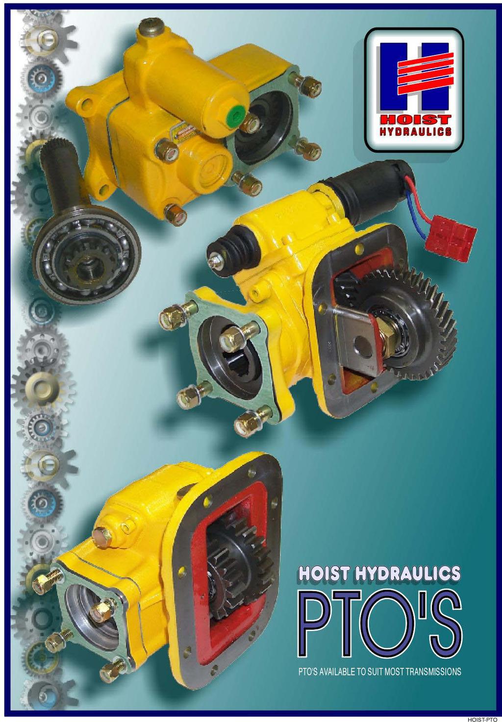
7 P.T.O. INSTALLATION 1 2 For manual shift transmissions, drain transmission fluid. For automatic transmissions, do NOT drain transmission fluid. Remove cover plate. 3 Place a clean rag in the opening to prevent dirt from getting in the transmission. Clean mounting pad with spatula or wire brush. Remove rag from transmission. 4 Install the studs supplied. Torque the studs to lbs.-ft. (6 bolt pad) or lbs.-ft. (8 bolt pad). 5 Place mounting gasket/shim over studs. A thin coating of grease is recommended to seal and hold gasket/shim in place. Do not use a permanent sealant. Use grease only!! Ensure that between the teeth of the gearbox and those in the Power Take-off is a backlash of mm N.B. Do not use more than 3 gasket/shims. 6 Fit the Power Take-off to the gearbox. On the Power Take-off there is a cap which, if unscrewed, is large enough to allow manual checking of backlash between the Power Take-off and the gears of the gearbox. The correct fitting of the P.T.O. is influenced by the fitters ability to correctly fit the P.T.O., by firstly tightening the lock nuts to a minimum torque and to operate the P.T.O. for a short period remembering that the gearbox and the P.T.O. are turning without oil. This allows the gears in the gearbox to self-align and also you are able to check for any excessive noise. FITTING INSTRUCTIONS 7 Fit the Power Take-off tightly onto the gearbox. Remember to use a washer and loctite. Torque the nuts to 20 lbs.-ft. for M8 threads and 40 lbs.-ft. for M10 threads. Re-fill the gearbox with oil. Note: Before re-filling the gearbox with oil it is advisable to check the noise level of the Power Take-off by using it for a short time (remembering that at this moment there is no lubricant in the gearbox). If the Power Take-off produces a hissing noise, this means that there is insufficient backlash in which case another shim must be added. If the Power Take-off rattles, this indicates that there is too much backlash and the number of shims must be reduced. Once the gearbox has been re-filled with oil, make sure there are no leaks. If the Power Take-off becomes noisy after the additional assembly of a universal joint, make sure that the joint is not worn, nor the alignment angles are not out of phase. When using Power Take-off's in conjunction with universal joints the maximum recommended angle is 15 PAGE 2 CATAUG-5.P65/P2

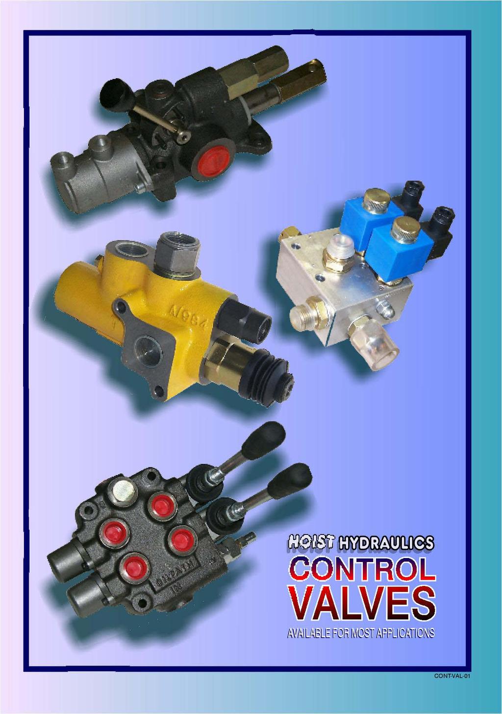
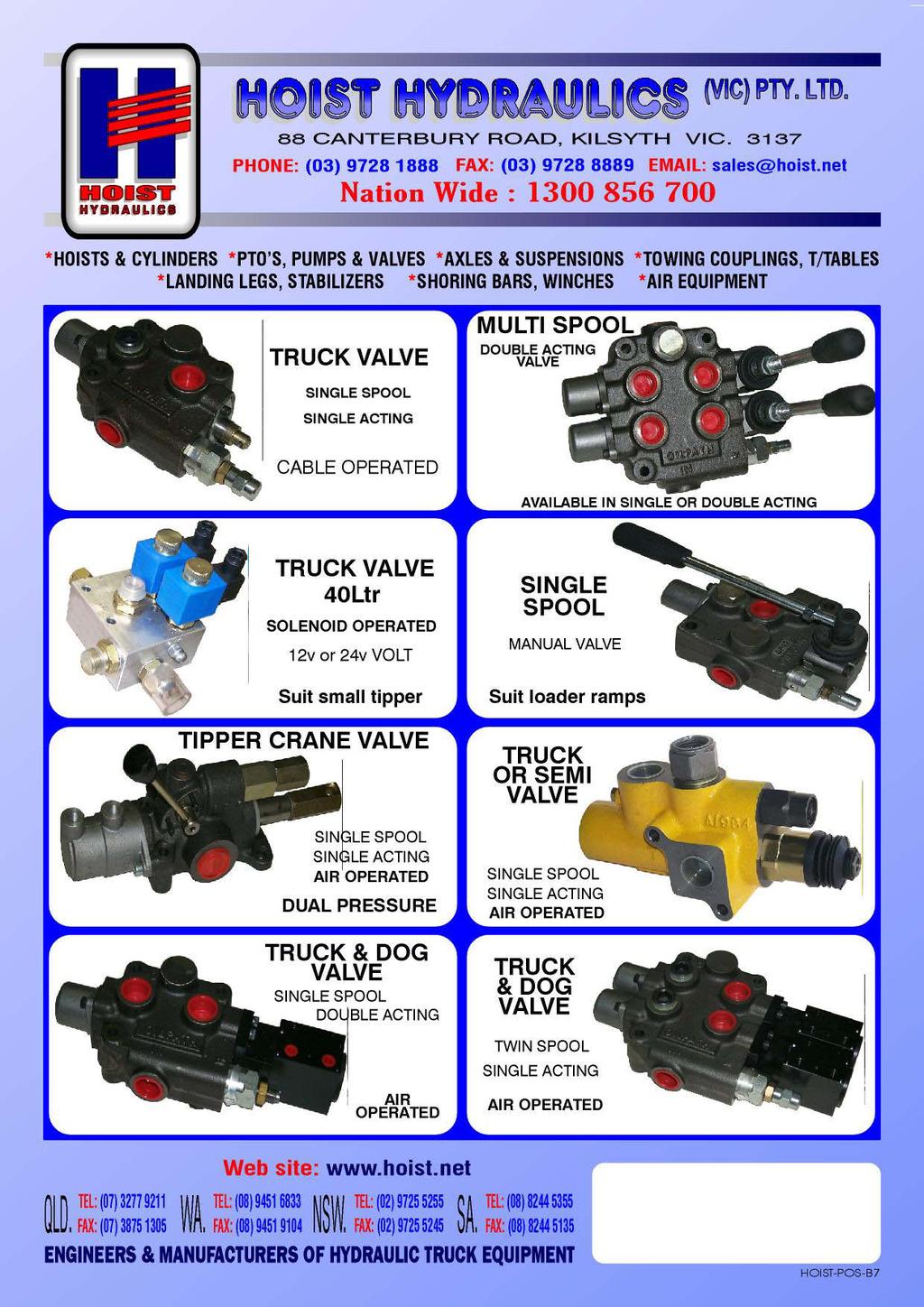
8 CONTROL VALVES CONTROL VALVE 60L 2000 psi 1/2" BSP PART No PART No PART No PART No PART No PART No PART No PART No PART No PART No "S" "D" "D" "DD" "DD" "DDD" "DDD" "DDDD" "DDDD" "DDDDD" (S/A SINGLE SPOOL) (D/A SINGLE SPOOL) (D/A SINGLE SPOOL) (D/A TWO SPOOLS) (D/A TWO SPOOLS) (D/A THREE SPOOLS) (D/A THREE SPOOLS) (D/A FOUR SPOOLS) (D/A FOUR SPOOLS) (D/A FIVE SPOOLS) CONTROL VALVE 120L 2000 psi 3/4" BSP PART No A PART No S RELIEF ASSEMBLY (S/A SINGLE SPOOL) PART No PART No PART No PART No PART No PART No PART No PART No PART No PART No PART No PART No PART No PART No S HI-FLOW D HI-FLOW D S/C D DETENT SS SD D UN ORING DS DD DD HI-FLOW DD DDD DDDD DDDD (S/A SINGLE SPOOL) (D/A SINGLE SPOOL) (D/A SINGLE SPOOL SPRING CENTRE) (D/A SINGLE SPOOL DETENT) (S/A TWO SPOOLS) (S/A SPOOL & D/A SPOOL) (D/A SINGLE SPOOL) (D/A SPOOL & S/A SPOOL) (D/A TWO SPOOLS) (D/A TWO SPOOLS) (D/A TWO SPOOLS) (D/A THREE SPOOLS) (D/A FOUR SPOOLS) (D/A FOUR SPOOLS) VALVES CATAUG-5.P65/P9 PAGE 3


9 ENGINEERS & MANUFACTURERS OF HYDRAULIC TRUCK EQUIPMENT. HOIST CONTROL VALVES TRUCK TRAILER VALVE (DUAL SPOOL) 110L PART No TRUCK TRAILER VALVE (SINGLE SPOOL) 110L PART No WOMBAT VALVE PART No TIPPER VALVE 170 LITRE PART No TIPPER VALVE 100 LITRE PART No CABLE TIPPER VALVE 60 LITRE PART No CABLE DIVERTER VALVE 110 LITRE PART No CABLE DIVERTER VALVE 250 LITRE PART No NOTE *** MULTI-FUNCTION VALVES ALSO AVAILABLE. OPERATED HOIST CONTROL VALVE These models are Modular 3 position 3 way open centre, air operated valves. These valves have specifically been designed for medium flows and quick turn around. The medium flow valve's features are built in check on pump side and relief valve, a pressure range upto 345 bars (5000 psi), manual override in case of air loss, and by using the appropriate air control, progressive lowering can be obtained. FROM PUMP 1/2 BSP TO HOIST 1/2 BSP IN TO LOWER IN TO LOWER IN TO RAISE TO TANK 1 BSP (UNDERSIDE NOT SHOWN) TO TANK 3/4 BSP (UNDERSIDE NOT SHOWN) IN TO RAISE TO HOIST 1 BSP FROM PUMP 3/4 BSP PART No (70 L/min ) PART No (170 L/min ) TECHNICAL DETAILS VALVES Flow 70 L/min flow rate PART No L/min flow rate PART No Pressure Preset maximum working pressure is 138 Bar (2000 psi) Air supply Min. 5 bar. (72.5 psi) Max 9 bar. (130.6 psi) PAGE 4 CATAUG-5.P65/P4

.")

10 ENGINEERS & MANUFACTURERS OF HYDRAULIC TRUCK EQUIPMENT. OPERATED HYDRAULIC HOIST CONTROL VALVE "WOMBAT MODEL" PART No BACK VIEW IN TO RAISE FRONT VIEW FROM PUMP IN TO LOWER FROM PUMP TO HOIST TO TANK ELECTRICALLY OPERATED HOIST CONTROL VALVE Model is a Modular 3 position open centre, 12 Volt electrically operated valve. This valve has specifically been designed for medium flows for quick turn around. The valve features a built in check on pump side and relief valve, with a pressure range upto 250 bars (3625 psi). The unit is electrically operated eliminating the need to fit cables and levers in the cabin. OUT This unit is also available in 24 Volt Part No Solenoid 12 Volt Normally open Solenoid 12 Volt Normally closed IN 1/2" BSP IN TANK TECHNICAL DETAILS Flow 40 L/min flow rate Pressure TO TANK 1/2" BSP Preset maximum working pressure is 138 Bar (2000 psi) but capable of being reset to 250 bars (3625 psi) OUT 1/2" BSP Pressure switch VALVES Mass 2.0 Kg. CATAUG-5.P65/P3 PAGE 5
 ACCELERATOR VALVE PART No. 4592-50000 250L PART No.")


11 VALVES OPERATED HYDRAULIC HOIST CONTROL VALVE DIVERTER VALVE 3/4" BSP () (DOUBLE PRESSURE) 250L 2000 psi 1" BSP PART No L PART No DIVERTER VALVE 1" BSP () ACCELERATOR VALVE PART No L PART No FLOW CONTROL VALVE 0-30GPM 2000 psi 3/4" NPT PART No RESTRICTOR VALVE PART No PART No /8 BSP 1/2 BSP PILOT OPERATED D/A CHECK VALVE PART No PART No /8" BSP 1/2" BSP V1 V2 RESTRICTOR VALVE C1 C2 VALVES PART No PART No PART No /8" BSP 1/2" BSP 3/4" BSP OVERCENTRE VALVE PART No PART No PART No /2" BSP 1/2" BSP 3/4" BSP V Pilot C PAGE 6 CATAUG-5.P65/P8
12 CYLINDER (415mm CRS.) CYLINDER (LOCKING PIN) (TAIL GATE OR LOCKABLE BALL RACE) (SUIT CAR CARRIER) CYLINDER PART No SEAL KIT PART No K CYLINDER (BARE) SHORT CENTRES (360mm) (TAIL GATE OR LOCKABLE BALL RACE) PART No BOOSTER TYPE 30 PART No MAXI BRAKE TYPE 30/30 CYLINDER PART No SEAL KIT PART No K CYLINDER (ASSEMBLY) SHORT CENTRES (360mm) PART No HOLD BACK VALVE (TAIL GATE OR LOCKABLE BALL RACE) PART No PILOT TYPE PART No CYLINDER (ASSEMBLY) SHORT CENTRES (360mm) DUO MATIC PART No FEMALE PART No (TAIL GATE OR LOCKABLE BALL RACE) SOLENOID TYPE 12 Volt ASSEMBLY PART No Volt ASSEMBLY PART No CYLINDER (SMALL) DOUBLE ACTING PART No SPRING RETURN PART No MALE PART No BRAKE LINE BULKHEAD 1/2" BSP PART No CONTROLS CATAUG-1.P65/P5 PAGE 7
 EXHAUST (KNOB IN) DIVERTER VALVE FITTING INSTRUCTION")
 DIVERTER VALVE FITTING")
 FITTING INSTRUCTIONS")
13 DIVERTER VALVE FITTING INSTRUCTION NORMALLY CLOSED NORMALLY OPEN DIVERTER VALVE (SPRING OFFSET) PUSH / PULL S/A SWITCH SUPPLY IN (KNOB OUT) EXHAUST (KNOB IN) DIVERTER VALVE FITTING INSTRUCTION (SOLENOID TYPE SWITCH) DIVERTER VALVE (SPRING OFFSET) IN (P) EXHAUST (R) SWITCH S/ACTING 12V OR 24V SOLENOID NORMALLY CLOSED OVERRIDE NORMALLY OPEN PORT A (N/O) DIVERTER VALVE FITTING INSTRUCTION (REMOTE TYPE SWITCH) DIVERTER VALVE (SPRING OFFSET) IN (P) EXHAUST (R) S/ACTING PILOT SWITCH NORMALLY CLOSED NORMALLY OPEN FROM SWITCH IN CABIN PORT A (N/O) FITTING INSTRUCTIONS CATAUG-3.P65/P9 PAGE 17

14 This schematic diagram shows the layout of Air control lines and connections to the Hoist Hydraulic single control lever and valve system. This schematic diagram shows the layout of Air control lines and electrical wiring connections to the Hoist Hydraulic dual control lever and valve system. FITTING INSTRUCTIONS CATAUG-4.P65/P9 PAGE 19

15 POWER PACK SOLENOID TYPE 12V S/A 12V D/A 24V S/A 24V D/A 5 LITRE PART No PART No D 10 LITRE PART No PART No D 15 LITRE PART No PART No D 20 LITRE PART No PART No D 34 LITRE PART No PART No D 48 LITRE PART No PART No D 5 LITRE PART No PART No D 10 LITRE PART No PART No D 15 LITRE PART No PART No D 20 LITRE PART No PART No D 34 LITRE PART No PART No D 48 LITRE PART No PART No D WIRING DIAGRAMS FOR SINGLE ACTING SOLENOID VALVES WIRING DIAGRAMS FOR DOUBLE ACTING SOLENOID VALVES WARNING LIGHT IF REQUIRED PUSH LOWER TOGGLE SWITCH SINGLE POLE DOUBLE HOLD THROW RAISE LOWER PUSH RAISE FUSE PRESSURE SWITCH FUSE POWER PACKS HOLD LOWER RAISE WARNING LIGHT IF REQUIRED FUSE PRESSURE SWITCH PUSH RAISE WARNING LIGHT IF REQUIRED PUSH LOWER RELAY NORMALLY OPEN COIL FUSE PAGE 24 CATAUG-4.P65/P6
16 P.T.O. CABLE PART No INNER WIRE & KNOB ONLY 3.0M PART No INNER WIRE & KNOB ONLY 4.5M PART No CABLE KIT (ADJUSTABLE) 3.0M PART No CABLE KIT (ADJUSTABLE) 4.5M VALVE CABLE PART No CABLE KIT 1.0m PART No CABLE KIT 1.5m PART No CABLE KIT 2.0m PART No CABLE KIT 2.5m PART No CABLE KIT 3.0m PART No CABLE KIT 3.5m PART No CABLE KIT 4.0m PART No CABLE KIT 4.5m PART No CABLE KIT 5.0m PART No CABLE KIT 6.0m PART No CABLE ONLY PART No CABLE ONLY PART No CABLE ONLY PART No CABLE ONLY PART No CABLE ONLY PART No CABLE ONLY PART No CABLE ONLY PART No CABLE ONLY PART No CABLE ONLY PART No CABLE ONLY PART No INNER WIRE ONLY PER METRE PART No VALVE CABLE POST PART No PTO CABLE POST PART No PTO CABLE POST (METRIC) CABLES PART No PTO CABLE INSERT PAGE 26 CATAUG-3.P65/P4
Spearhead Excel 565, 605 & 645T
 1 Spearhead Twiga 5000, 6000, 6000LR & 6000 T Parts Book 11 th Edition February 2010 Green-Tec A/S Merkurvej 25 DK 6000 Kolding Tel: +45 7555 3644 Fax: +45 7555 4243 www.greentec.eu info@greentec.eu Spearhead
40041 Heavy Duty ADA System with Booster Bracket for JK Heavy Duty ADA System with Booster Bracket for 2012 to Current JK
 40041 Heavy Duty ADA System with Booster Bracket for 2007-2011 JK 40044 Heavy Duty ADA System with Booster Bracket for 2012 to Current JK 40049 Heavy Duty ADA System Universal for all vehicles (booster
Encore S28/L28/S33/L33/S38/L38. Section II. Parts and Service Manual (79049B)
") Encore S8/L8/S/L/S8/L8 Section II Parts and Service Manual (9049B) CLARKE TECHNOLOGY Operator's Manual - Encore S8/L8/S/L/S8/L8 - - HOW TO CORRECT PROBLEMS IN THE MACHINE PROBLEM CAUSE ACTION The machine
Encore S8/L8/S/L/S8/L8 Section II Parts and Service Manual (9049B) CLARKE TECHNOLOGY Operator's Manual - Encore S8/L8/S/L/S8/L8 - - HOW TO CORRECT PROBLEMS IN THE MACHINE PROBLEM CAUSE ACTION The machine
ILT - Series. Troubleshooting: ILT Twinfold Dual Cylinder Folding Unit
 - Troubleshooting: Twinfold Dual Cylinder Folding Unit Table of content: Page 1) Gate overview...2 2) Gate does not lower down.3 3) Gate is not lifting up....4 4) Electrical schematic 5 5) Hydraulic schematic...6
Spearhead TWIGA. TWIGA Reach Mower 555/600/655T 555FR/600FR. Edition 2.0 March 2011 Part No
 TWIGA Reach Mower 555/600/655T 555FR/600FR Edition 2.0 March 2011 Part No. 8999057 0 Contents Ordering Your Parts 3 A Frame 4 Tank 6 Slew Post 8 Lift Frame 10 Tank Lid 12 Rear Panel 13 Stabiliser Brackets
DIAGNOSTIC TROUBLESHOOTING INDEX
 DIAGNOSTIC TROUBLESHOOTING INDEX Curtis Industries, LLC. 111 Higgins Street Worcester, MA 01606 Telephone: (508) 853-2200 Fax: (800) 876-9104 www.snoproplows.com TROUBLESHOOTING INDEX - BY PROBLEM Section
Vickers Pressure Relief Solenoid Operated, Two-Stage Directional Control Valve DG5S4-02 Flows to 115 l/min (30 USgpm) Pressure to 210 bar (3000 psi)
 Pressure to 210 bar (3000 psi)") Vickers Pressure Relief Solenoid Operated, Two-Stage Directional Control Valve DG5S4-02 Flows to 115 l/min (30 USgpm) Pressure to 210 bar (3000 psi) Revised 2/93 GB C 2037 Table of Contents Model Code...................................................................................................
Vickers Pressure Relief Solenoid Operated, Two-Stage Directional Control Valve DG5S4-02 Flows to 115 l/min (30 USgpm) Pressure to 210 bar (3000 psi) Revised 2/93 GB C 2037 Table of Contents Model Code...................................................................................................
PRODUCT INFORMATION FAQ s
 PRODUCT INFORMATION FAQ s Directional Control Valves General....... Page 2 Directional Control Valves Electric....... Page 4 Directional Control Valves Options....... Page 6 Directional Control Valves
Spearhead TWIGA. TWIGA Reach Mower 545 / 595 / 640T. Edition 1.1 April 2014 Part No
 TWIGA Reach Mower 545 / 595 / 640T Edition 1.1 April 2014 Part No. 8999016 0 Contents Ordering Your Parts 3 A Frame 4 Tank 6 Tank Lid 8 Rear Panel 10 Slew Post 12 Lift Frame 14 Main Arm 16 Dipper Arm 18
Spearhead TWIGA. TWIGA Reach Mower 555/600/655T/700T 555FR/600FR. Edition 2.5 June 2014 Part No
 TWIGA Reach Mower 555/600/655T/700T 555FR/600FR Edition 2.5 June 2014 Part No. 8999057 0 Contents Ordering Your Parts 3 A Frame 4 Tank 6 Slew Post 8 Lift Frame 10 Tank Lid 12 Rear Panel 13 Stabiliser Brackets
ILQ TROUBLESHOOTING GUIDE
 TROUBLESHOOTING GUIDE Rev. 1.1, Date 1-15-2009 1 Series (until June 2008) Troubleshooting: with rectangle circuit board on driver side Table of content: Page 1) Gate overview and connector setup...2 2)
DP3 Pump. 3:1, Air-operated, Oil. General. Operation. Technical Data. Installation R0 10/09. 35a 35b 35c
 DP3 Pump 3:1, Air-operated, Oil General The DP3 Pump is a compressed air-operated piston reciprocating medium pressure pump. Suitable for medium flow transfer of high viscosity lubricants and for oil delivery
Hyva Valves Introduction
 Introduction Hyva tipping valves Hyva offers a complete range of tipping valves to be used for different cylinder volumes. The T 0 & 00 valve can be used for flows up to 0 litre per minute. The pressure
SWINGTRIM Swingover Cutterbar Trimmer
 Publication 117(PM) December 2007 Part No. 1090850 Revision: 2 SWINGTRIM Swingover Cutterbar Trimmer Parts Manual For best performance USE ONLY McCONNEL SERVICE PARTS To be assured of the latest design
ILD plus 35, 44, 55, 66
 ILD plus 3,,, Column gate PARTS BREAK DOWN Interlift Inc. a member of MBB Palfinger TEL. ()-77- FAX. (2)--31 72 Whitehead Road, Trenton, NJ 01 TEL.(0)-7-200 FAX.(0)-7-201 DATE: /2/20 REVISION: 1. ILD plus
MODEL D ELECTRIC TWO-STAGE HYDRAULIC PUMP
 l e s i MADE IN U.S.A. FOR HYDRAULIC w i t h ANS I B4 0. 1 Parts List for: SPX Hydraulic Technologies 5885 11th Street Rockford, IL 61109-3699 USA powerteam.com Tech Services: +1 800 477 8326 Fax: +1 800
Instruction Manual. Maple 7/15 Pump. Model
 Maple 7/15 Pump Model 10 40 41 Page 2 of 16 Specification Pump Ratio 15:1 Max. Air Pressure Inlet Max. Fluid Pressure Nominal Flow Volume / Cycle 7 Bar 105 Bar 0.166 Litres 0.044 US Gall Fluid Output @
Port Flow Rate/ Function Series Actuators Page Number Size Factor
 Section dex Port Flow Rate/ Function Series Actuators Page Number Size Factor 0- Cv = 0.05 Way Modular Solenoid. -. & to Way Manifold /8 NPT Cv = 0. Way, Position Modular /8 NPT Cv = 0.05 Way Hex Solenoid.5.6
POWERSHIFT TRANSMISSION
 1. Specifications... 5-3 2. Structure... 5-4 2.1 Torque converter... 5-4 2.2 Transmission... 5-5 2.3 Power Train Line... 5-6 2.4 Control Valve... 5-7 2.5 Main Regulator Valve... 5-7 2.6 Torque Converter
PA47 Mk3 HEDGECUTTER / MOWER. Parts Manual. Publication 555 October 2008 Part No Revision:
 Publication 555 October 2008 Part No. 41571.55 Revision: 17.03.09 PA47 Mk3 HEDGECUTTER / MOWER Parts Manual For best performance USE ONLY GENUINE SERVICE PARTS To be assured of the latest design improvements
Installation & Operation Manual. IMPORTANT: This manual contains important information. READ AND KEEP FOR REFERENCE.
 Elecronic Preset Meter 2 Industrial Handheld Series Model EPM2-IND Standard Series IMPORTANT: This manual contains important information. READ AND KEEP FOR REFERENCE. IOM-139-02-EN (1-12) 53400-139 Rev.
DP5 Pump. 5:1, Air-operated, Heavy Duty, Oil. General. Operation. Technical Data. Installation R1 09/10
 DP5 Pump 5:1, Air-operated, Heavy Duty, Oil General The DP5 Pump is a compressed air-operated reciprocating piston medium pressure pump. These pumps are suitable for distribution of all types of light
and RD5000 or by the Utility section in the Series 20 valves. 7. The internal pilot pressure is used to initiate the spool shift when a solenoid is en
 December 2004 SOLENOID OPERATORS ON DIRECTIONAL CONTROL VALVES Solenoid valves us an electric signal to control the flow. BASIC TYPES 1. On Off solenoid valves. When energized, they are either fully on
D07 & D08. Series 35 Solenoid Valves D07 D Friendship Drive, Magnolia, TX Tel.: Fax:
 GENERL FEURES SNDRD FEURES High ressure/ High Flow: 65 gpm/ psi ilot Operation: Main spool controlled by D0 solenoid pilot valve- allows for addition of modular valves to reduce shifting shock. Oil Immersed,
GROUP 3 HYDRAULICS 636 EXTENDO PARTS BOOK
 GROUP 3 HYDRAULICS 636 EXTENDO ELECTRICAL SCHEMATIC FOR 636 & 5528, AL-11969... 3-4 ELECTRICAL PLUG-INS SCHEMATIC, BL-10012... 3-7 HYDRAULIC SCHEMATIC, AL-11355... 3-8 HYDRAULIC SCHEMATIC WITH OPTIONAL
22 SECTION 18 - CLUTCH - CHAPTER 1
 22 SECTION 8 - CLUTCH - CHAPTER PTO CLUTCH CONTROL SYSTEM ADJUSTMENT 43 See Section 3 PTO for details on PTO clutch servo control adjustment, and for the PTO engage switch adjustment. SECTION 2 - TRANSMISSIONS
MP18 Stacking Valve System Technical Information Manual
 Electric Drives and Controls Hydraulics Linear Motion and Assembly Technologies Pneumatics Service MP18 Stacking Valve System Technical Information Manual The Drive & Control Company Copyright 1996 Bosch
Arctic Equipment Manufacturing Corporation M3551 Hydraulic Power Unit. Table of Contents
 Arctic Equipment Manufacturing Corporation M3551 Hydraulic Power Unit Table of Contents General Information...2 Hydraulic Information Diagrams...7 Hydraulic and Electrical Installation...10 Parts List...11
PA 32. Parts Manual HEDGE/GRASS TRIMMER. Publication 410 August 2001 Part No Revision:
 Publication 410 August 2001 Part No. 41570.11 Revision: 17.01.07 PA 32 HEDGE/GRASS TRIMMER Parts Manual For best performance USE ONLY GENUINE McCONNEL SERVICE PARTS To be assured of the latest design improvements
TH406 / TH407 Recommended Parts List
 Basic Engine & Related System (Mechanical) Primary Fuel Filter - Mechanical 1R-1804 Secundary Fuel Filter - Mechanical 252-6338 Air Filter Primary Element 206-5234 Air Filter Secondary Element 206-5235
MP18/SIC & SIO Stacking Valve System Technical Information Manual
 Electric Drives and Controls Hydraulics Linear Motion and Assembly Technologies Pneumatics Service MP18/SIC & SIO Stacking Valve System Technical Information Manual The Drive & Control Company Copyright
Vision 17B/BT. Section II Parts and Service Manual (78454B) CLARKE TECHNOLOGY Operator's Manual - Vision 17B/BT Page -23-
 CLARKE TECHNOLOGY Operator's Manual - Vision 17B/BT Page -23-") Vision 17B/BT Section II Parts and Service Manual (78454B) Operator's Manual - Vision 17B/BT Page -23- HOW TOO CORRECT PROBLEMS IN THE MACHINE PROBLEM CAUSE ACTION There isn't any solution flow. The solution
Vision 17B/BT Section II Parts and Service Manual (78454B) Operator's Manual - Vision 17B/BT Page -23- HOW TOO CORRECT PROBLEMS IN THE MACHINE PROBLEM CAUSE ACTION There isn't any solution flow. The solution
VALVE AND PLUMBING KIT 2408TL LOADER AGCO & MASSEY FERGUSON TRACTORS
 ASSEMBLY MANUAL Keep With Operator s Manual VALVE AND PLUMBING KIT 2408TL LOADER AGCO & MASSEY FERGUSON TRACTORS AGCO MASSEY FERGUSON CAB ROPS ST34A 1533 X ST41A 1540 N/A X TRACTOR AND VALVE KIT GENERAL
Operating and Maintenance Instructions for: Figure 79 Pneumatic Actuators (U/E options)
") for: Figure 79 Pneumatic Actuators (U/E options) Introduction The Keystone Figure 79 Pneumatic Actuator range is available in three mounting options, as follows:- 79U - Keystone Mounting Standard 79E -
for: Figure 79 Pneumatic Actuators (U/E options) Introduction The Keystone Figure 79 Pneumatic Actuator range is available in three mounting options, as follows:- 79U - Keystone Mounting Standard 79E -
J1 Plug Pin Identification
 D D8 D D D D ART_8 J 8 D D0 R R R R TB 80 D D D D D D J Plug Pin Identification PIN # WIRE # SIGNAL FUNCTION 0 INPUT Drive Reverse INPUT Drive Forward OUTPUT Brake, Decel Valve signal 8 INPUT Steer Left
SUSSMAN 'ES, HU and MBA' SERIES PARTS LIST EFFECTIVE: 7/24/2017
 EFFECTIVE: 7/24/2017 STEAM SAFETY VALVES 99136 100 PSIG 1/2" NPT (ES12 to ES72) 99137 100 PSIG 1" NPT (ES84 to ES180) 99132 15 PSIG 1/2" NPT (ES12 to ES48, HU40 to HU140) 99297V 15 PSIG 3/4" NPT (ES60
J1 Plug Pin Identification
 D5 D8 D7 D4 D5 D ART_8 J 4 8 D D0 7 R R R R4 TB 80 D D D D4 D D J Plug Pin Identification PIN # WIRE # SIGNAL FUNCTION 0 INPUT Drive Reverse INPUT Drive Forward OUTPUT Brake, Decel Valve signal 4 8 INPUT
J1 Plug Pin Identification
 D5 D D D D5 D ART_ J D D0 R R R R TB 0 D D D D D D J Plug Pin Identification PIN # WIRE # SIGNAL FUNCTION 0 INPUT Drive Reverse INPUT Drive Forward OUTPUT Brake, Decel Valve signal INPUT Steer Left 5 OUTPUT
LOAD SENSE SECTIONS. Series 20. Directional Control Valves NEED NEW PIC VALVES STANDARD FEATURES SPECIFICATIONS
 Directional Control Valves LOAD SENSE SECTIONS NEED NEW PIC Series 20 STANDARD FEATURES Control and reduced Dead Band (20I) and Tie Rod Kits SPECIFICATIONS Pressure Rating Foot Mounting Maximum Operating
Lime Spreader. Model SL6. Illustrated Parts Breakdown. Front Hydraulics Rear Hydraulics Manifold Components. Spinner Assembly
 Lime Spreader Model SL Illustrated Parts Breakdown Page Page Page Page Page Page Page Page Page Page 0 Front End Front Hydraulics Rear Hydraulics Manifold Components Floor & Apron Axle Assembly Apron Drive
liu OIL TRANSFERING BETWEEN
 4007-9 When the lift spool is in the float position, oil from the pump flows through the open center passage to the outlet. The two work ports are directly connected through the hollow center of the spool.
Table of Contents.
 3551 Table of Contents Operating Information...2 Hydraulic Information Diagrams...7 Hydraulic and Electrical Installation...10 Parts List...11 Troubleshooting...15 Page 1 M3551 M3551 Operating Information
ILD PLUS 33, 44, 55, 66
 ILD PLUS 33,,, PARTS MANUAL ECN-M0XXX Rev. 1., Date 0--201 Part #0-1-000 13 Piuma Ave., Cerritos, CA 0703 Tel ()-77- Fax (2)--31 72 Whitehead Road, Trenton, NJ 01 Tel (0)-7-200 Fax (0)-7-201 Visit our
ONBOARD AIR HOOKUP KIT
 ONBOARD AIR HOOKUP KIT PART NO. 20052 (30 amp - 110PSI on, 150PSI off) PART NO. 20053 (30 amp - 85PSI on, 105 PSI off) PART NO. 20055 (30 amp - 90 PSI on, 120 PSI off) IMPORTANT: It is essential that you
KEYSTONE FIGURE 79 PNEUMATIC ACTUATOR OPERATING AND MAINTENANCE INSTRUCTIONS
 Operating and Maintenance Instructions for: Figure 79 Pneumatic Actuators (U/E options) Double Acting Actuator 4. If pipelines are hydraulically tested, then the lines should be blown down with high pressure
Residential R.O. components
 Residential R.O. components WATER TREATMENT COMPONENTS 1,8 RESIDENTIAL CSM MEMBRANES 2015 10-01-01-EN 1,8 RESIDENTIAL CSM MEMBRANES Ref. Model Name RE1810-30 DA050A RE1810-50 RE1812-35 DA050 DA051 DA052
ASSEMBLY MANUAL SMC 2491 LOADER VALVE AND PLUMBING KIT INSTRUCTIONS KUBOTA TRACTORS
 ASSEMBLY MANUAL Keep With Loader Operator's Manual SMC 2491 LOADER VALVE AND PLUMBING KIT INSTRUCTIONS KUBOTA TRACTORS MODEL 2WD 4WD LESS CAB WITH CAB L5450 X X Valve and plumbing kit can be installed
TC20 Chain Driven Power Take-Off Overhaul Instructions
 TC20 Chain Driven Power Take-Off Overhaul Instructions Table of Contents Section Page Introduction 4 Ordering Repair Parts 4 General Information 5 Special Tools 6 Disassembly See Page 2 Reassembly See
TRAILER MOUNTED PUMP MODEL B50 DRIVE CYLINDER CIRCUIT HYDRAULIC COMPONENTS & SCHEMATIC
 DRIVE CYLINDER CIRCUIT HYDRAULIC COMPONENTS & SCHEMATIC PAGE 01 SINGLE SHIFT SWING TUBE CIRCUIT HYDRAULIC COMPONENTS & SCHEMATIC PAGE 02 DUAL SHIFT SWING TUBE CIRCUIT HYDRAULIC COMPONENTS & SCHEMATIC PAGE
VALVE AND PLUMBING KIT INSTRUCTIONS SMC 84Q & 2408 LOADERS NEW HOLLAND TRACTORS MODEL 2WD 4WD LESS CAB WITH CAB 1720 X X X 1920 X X X
 ASSEMBLY MANUAL Keep With Operator s Manual VALVE AND PLUMBING KIT INSTRUCTIONS SMC 84Q & 2408 LOADERS NEW HOLLAND TRACTORS MODEL 2WD 4WD LESS CAB WITH CAB 1720 X X X 1920 X X X TRACTOR AND VALVE KIT GENERAL
Modular Unit 6MB HYDRANOR MODULAR UNIT 6MB GENERAL DESCRIPTION. 6MB-200-**-2C General Arrangement. Rev
 MODULAR UNIT 6MB GENERAL DESCRIPTION Figure 1 6MB-200-**-2C General Arrangement Rev. 5 5.1.1 Figure 2 General Arrangement 6MB-650-**-2C The Modular Units 6 MB is a complete unit for controlling of hydraulically
Section FF C Front Frame - Frame / Covers / Steps
 Section FF-1 830800C & 840 Front Front Frame - - Frame Frame / Covers / Covers / Brackets / Steps / Steps 830C Front Frame - Frame / Covers / Steps Last Updated - 05/16 Front Frame - Frame / Covers / Steps
Directional Valves. Pilot Operated Directional Valves. Vickers. Service Data
 Service Data Vickers Directional Valves Pilot Operated Directional Valves Eaton Hydraulics, Incorporated 14615 Lone Oak Road Eden Prairie, Minnesota 55344-2287 U.S.A. 5007.04/EN/0799/S DG5V - 8 - S/H -
BW0511FP. ByWire Elements BW0511FP Flow Sharing Element Interface IBW0511
 ywire Elements Flow Sharing Element Interface IW05 efore use, carefully read the GENERL INSTRUCTIONS FOR USE OF DIRECTIONL CONTROL VLVES Technical data Nominal flow Nominal pressure 35 l/min - P=8 bar
INSTRUCTIONS & MAINTENANCE SHEET PORTABLE BATTERY HYDRAULIC POWERPACK HAB1102
 INSTRUCTIONS & MAINTENANCE SHEET PORTABLE BATTERY HYDRAULIC POWERPACK HAB1102 LARZEP, S.A. Avenida Urtiaga, 6 48269 MALLABIA, SPAIN Tel. +34 943 171200 Fax. +34 943 174166 e-mail: sales@larzep.com www.larzep.com
 HIAB 166 E-3 Duo HIAB 166 DUO CE-marked. Crane base The HIAB 166 has a base with 3 point bridge, suitable for truck mounting. It is provided with a single slewing system of rack/pinion type,
KEITH KFD Series OWNERS MANUAL Original Instructions
 KEITH Manufacturing Co. World Headquarters 800-547-6161 541-475-3802 541-475-2169 fax KEITH Series OWNERS MANUAL Original Instructions *Durable and dependable construction *Simple Installation *Low maintenance
DIAGNOSTIC FLOW CHART FOR E-58H & E-61H ELECTRO LIFT UNITS WITH TOUCH PAD
 DIAGSTIC FLOW CHART FOR E-58H & E-61H ELECTRO LIFT UNITS WITH TOUCH PAD These charts are intended to be used as an aid in diagnosing problems on the Electro Lift units. They are not a substitute for factory
P844L3MS For Models: NL844L3.1MS1 and NL844L3.1MS2 PARTS CATALOG. Marine Generators Marine Diesel Engines Land-Based Generators
 P844L3MS For Models: NL844L3.1MS1 and NL844L3.1MS2 PARTS CATALOG Marine Generators Marine Diesel Engines Land-Based Generators CALIFORNIA Proposition 65 Warning: Diesel engine exhaust and some of its constituents
TEREX Woodsman 730 BRUSH CHIPPER
 Woodsman 730 BRUSH CHIPPER Parts Manual Customer Dealer S/N Frame # Date Woodsman 150 Commerce Drive, Farwell MI 486 Phone: (800) 953-553 Fax: (989) 588-487 Flipper Discharge Chute Hand Crank Belt Shield
ASSEMBLY MANUAL. Keep With Operator s Manual
 ASSEMBLY MANUAL Keep With Operator s Manual 2-6347 VALVE AND PLUMBING KIT INSTRUCTIONS SMC 64Q LOADER KUBOTA TRACTORS MODEL 2WD 4WD LESS CAB WITH CAB B2150DT & B2150HSD X X B8200DT & B8200HSD X X B9200DT
TC2000. This control box is typically located in the cab of the truck and the cable runs back to the auxiliary plug at the front of the trailer.
 ELECTRICAL TC2000 Part No: 3500128 Air Ride Control Box With 30 ft. Cable This control box is typically located in the cab of the truck and the cable runs back to the auxiliary reverse ground plug at the
DIAGNOSTIC FLOW CHART FOR E-57 & E-60 ELECTRO LIFT UNITS WITH TOUCH PAD
 DIAGSTIC FLOW CHART FOR E-57 & E-60 ELECTRO LIFT UNITS WITH TOUCH PAD These charts are intended to be used as an aid in diagnosing problems on the Electro Lift units. They are not a substitute for factory
INSTALLATION AND USER MANUAL
 INSTALLATION AND USER MANUAL SDKIT-730 & SDKIT-734 100% Bolt-On 150 PSI Train Horn System for 2011-2015 F-250 & F-350 Super Duty P/N SDKIT-730 P/N SDKIT-734 Thank you for purchasing a Kleinn Air Horns
Spare Parts List - DUO 500 & DUO 2
 Spare Parts List - DUO 00 & DUO 2 Issue Date 03//200 Part No. 930.000 Issue B MD - 200 Water Inlet -2 Water Drainage 3-4 Wash Pump -6 Bottom Washing / Rinsing System 7-8 Top Washing / Rinsing System DUO
PARTS ORDERING INFORMATION
 RP-268 REPAIR PARTS FOR VE268 Roll Grooving Tool PARTS ORDERING INFORMATION When ordering parts the following information is necessary for the Victaulic Tool Company to promptly process the order and send
N-Line Valves. Surface Stepping Actuators
 N-Line Valves Surface Stepping Actuators N-Line Valves SA-II Surface Stepping Actuator For Rising Stem Chokes The N-Line Valves SA-II Stepping Actuator is a pneumatically or hydraulically powered rotary
GS12 Grape Spreader. Illustrated Parts Breakdown
 GS Grape Spreader Illustrated Parts Breakdown Page Front End Assembly Page Axle Assembly Page Floor & Apron Page Pump Assembly Page Page Hydraulics Manifold Components Page Gearbox Components S/N - Page
VARNA Products 15 GPM (57 LPM) Prelube Kit for MTU 4000 Series Marine Engines
 Prelube Kit for MTU 4000 Series Marine Engines") VARNA Products 15 GPM (57 LPM) Prelube Kit for MTU 4000 Series Marine Engines Installation and Users Manual For the following Prelube Kits: VARNA Products P/N 6423 Kit for 208 VAC 3 Phase VARNA Products
VARNA Products 15 GPM (57 LPM) Prelube Kit for MTU 4000 Series Marine Engines Installation and Users Manual For the following Prelube Kits: VARNA Products P/N 6423 Kit for 208 VAC 3 Phase VARNA Products
485 - NC NO/DA DN
 485 - NC 285 - NO/DA DN 25-100 The 485/285 diaphragm valve is particularly suitable for shutting off and regulating abrasive or dirty fluids. The new internal geometry of the body optimises fluid dynamic
Appendix 4 Exploded Views and Parts Lists
 Enclosure Drawing No. 0D8-F 7 0 4 4 4 6 8 4 7 4 6 44 4 46 8 7 6 47 4 8 0 4 0 8 6 6 4 0 4 7 4 40 TO CARB 4 8 Generac Power Systems, Inc. Enclosure Drawing No. 0D8-F 0D68 TRAY, ENCLOSURE 0D64 PANEL, ENCLOSURE
Group 3 Hydraulics 3-1
 Group 3 Hydraulics Fig. 3-1, Hydraulic Schematic, AL-10531... 3-2 Main Hydraulic Pump Assembly, LL-299-1262... 3-4 Main control Valve Assembly, LL-3674-181 (4 Section)... 3-6 Spool Control Cover and Seal
OUR MISSION IS FOR YOU TO ACHIEVE YOUR GOALS BY PROVIDING INNOVATIVE & QUALITY PRODUCTS.
 OUR MISSION IS FOR YOU TO ACHIEVE YOUR GOALS BY PROVIDING INNOVATIVE & QUALITY PRODUCTS. FOR ALL YOUR HYDRAULIC NEEDS www.chchydraulic.com VALVES AND BLOCKS BLOCK MANIFOLDS Hydro Custom manifolds allows
Contents. Directional Control Valve 2 Series CV Unibody. Page 3-4. General Information. Page 5. Technical data. Page 6. Performance Curves
 Contents Page 3-4 Page 5 Page 6 Page 7 Page 8 Page 9 Page 10 Page 11-12 Page 13 Page 14 Page 15 General Information Technical data Performance Curves Dimensions - Basic Valve Dimensions - Unibody Secondary
Service Tools. Service and Repair Manual Model 900/950/990 ITEM PART NO. DESCRIPTION ITEM PART NO. DESCRIPTION ITEM PART NO.
 12 1 3 2 4 5 8 10 6 7 9 11 14 24 12 13 17 22 29 18 23 25 19 26 15 20 27 21 16 22 33 37 38 32 31 36 30 34 35 40 41 42 43 ITEM PART NO. DESCRIPTION 1 9170 0231 30 LONG ALLEN KEY 2 9170 0737 20 3/32 PIN PUNCH
VALVE AND PLUMBING KIT 4211 LOADER CASE IH JX55, JX65, JX75,JX85, AND JX95 TRACKTORS NON-CAB
 ASSEMBLY MANUAL 2-7293 Keep With Operator s Manual VALVE AND PLUMBING KIT 42 LOADER CASE IH JX55, JX65, JX75,JX5, AND JX95 TRACKTORS NON-CAB Valve and plumbing kit can be installed using tools ordinarily
PNEUMATICALLY ACTUATED 2-WAY
 482 DN 25-65 The 482 diaphragm valve is particularly suitable for shutting off and regulating abrasive or dirty fluids. The new internal geometry of the body optimises fluid dynamic efficiency by increasing
HEAVY DUTY ONBOARD AIR SYSTEM
 HEAVY DUTY ONBOARD AIR SYSTEM PART NO. 10005 IMPORTANT: It is essential that you and any other operator of this product read and understand the contents of this manual before installing and using this
DEL HYDRAULICS AIR CONTROL CATALOG
 DEL HYDRAULICS AIR CONTROL CATALOG www.del.us.com 2 Dump Truck Valves AIR CONTROL VALVES DAV 1201: On-Off Air Valve DAV 1202: Dump Pump Air Valve DAV 1203: Dump Pump Valve with Automatic PTO Disengagement
Available manual, pneumatic, and hydraulic spool control kits.
 Fitted with a main pressure relief valve and a load check valve on every working section. Available with parallel circuit. Optional carry-over Variety of port valves (auxiliary valves) Available manual,
Solar Thermal. Grant Solar Pump Station Installation & Servicing Instructions
 Solar Thermal Grant Solar Pump Station Installation & Servicing Instructions Part No. DOC 96. Rev 02. October 2012 Important Note Important Note for Installers The Pump Station supplied with your Grant
HY-SPEC CATALOGUE - HYDRAULIC VALVES. Hydraulic Valves. Visit our website Catalogue
 HY-SPEC CATALOGUE - HYDRAULIC VALVES Hydraulic Valves Catalogue Visit our website HY-SPEC PRODUCT FAMILY HY-SPEC CATALOGUE - AC/DC POWER PACKS HY-SPEC CATALOGUE - GAS ENGINE PRODUCTS Accessories AC/DC
POMPE À DIAPHRAGME DIAPHRAGM PUMP ASYBCO
 POMPE À DIAPHRAGME DIAPHRAGM PUMP ASYBCO DIAPHRAGM PUMP Hydra-Cell Features Heavy-duty industrial construction Quiet, smooth operation Hydraulically balanced diaphragms Runs dry without damage Positive
Troubleshooting the Transmission Hydraulic System
 Testing and Adjusting IT28F INTEGRATED TOOLCARRIER POWER TRAIN Testing And Adjusting Introduction Reference: For Specifications with illustrations, refer to SENR5974, IT28F Integrated Toolcarrier Power
215 Service Manual SERVICE MANUAL. 215 Series Axle
 SERVICE MANUAL 215 Series Axle Issue 1 - January 2002 CONTENT: 1 INTRODUCTION... Page - 1-2 GENERAL DESCRIPTION... Page - 1-3 IDENTIFICATION... Page - 1-4 GENERAL SERVICE INFORMATION... 4.1 Routine Maintenance...
LPD. Spare parts list. Post drivers heavy-duty HD-T, HD-RV Atlas Copco Construction Tools AB No f
 LPD HD-T, HD-RV Post drivers heavy-duty Contents Contents General information................................................................ 5.....................................................................
(F*) - DG5V -10- * - (R) - (B) - **(L) - (**) - (X) - (*) - (E) - (T) - (*) - (V)M - (S*) - * ** * * (L) - (*) ** - (***) (EN***)
 - DG5V -10- * - (R) - (B) - **(L) - (**) - (X) - (*) - (E) - (T) - (*) - (V)M - (S*) - * ** * * (L) - (*) ** - (***) (EN***)") Service Data Vickers Directional Valves Pilot Operated Directional Valves (F*) - DG5V -10- * - (R) - (B) - **(L) - (**) - (X) - (*) - (E) - (T) - (*) - (V)M - (S*) - * ** * * (L) - (*) ** - (***) - 10
Service Data Vickers Directional Valves Pilot Operated Directional Valves (F*) - DG5V -10- * - (R) - (B) - **(L) - (**) - (X) - (*) - (E) - (T) - (*) - (V)M - (S*) - * ** * * (L) - (*) ** - (***) - 10
Website: ELIMINATOR MD. (701) (800)
 (800)") Website: www.tbei.com E-mail: sales@tbei.com ELIMINATOR MD www.rugbymfg.com sales@rugbymfg.com (701) 776-5722 (800) 533-0494 1228633 1 DATE PURCHASED BODY SERIAL NUMBER HOIST SERIAL NUMBER CYLINDER SERIAL
Website: www.tbei.com E-mail: sales@tbei.com ELIMINATOR MD www.rugbymfg.com sales@rugbymfg.com (701) 776-5722 (800) 533-0494 1228633 1 DATE PURCHASED BODY SERIAL NUMBER HOIST SERIAL NUMBER CYLINDER SERIAL
VALVE AND PLUMBING KIT 2409 LOADER CUB CADET & KIOTI TRACTORS
 ASSEMBLY MANUAL Keep With Operator s Manual VALVE AND PLUMBING KIT 2409 LOADER CUB CADET & KIOTI TRACTORS TRACTOR MODELS CUB CADET 8404, 8454 KIOTI DK45, DK50 ROPS X X TRACTOR AND VALVE KIT GENERAL INFORMATION
Magnesium Option, Late Model Front Seal, Viton, P/N 67256V Rear Seal, Viton, P/N 67257V Shifter Installed Heat Treated Yoke, P/N
 DESCRIPTION OPTION Magnesium Option, Late Model 80100L Front Seal, Viton, P/N 67256V 80109 Rear Seal, Viton, P/N 67257V 80110L Shifter Installed 80112L Heat Treated Yoke, P/N 62946-6 80119-6 Heat Treated
Installation Instructions Clamp Opening Control - Switch Operated
 Installation Instructions Clamp Opening Control - Switch Operated 45-078, REV. 8/14 1 TABLE OF CONTENTS SECTION 1 PURPOSE... 3 SECTION 2 INSTALLATION... 4 Test Installation...6 Disabling The System...6
Installation Instructions Rotation Control Kit
 Installation Instructions Rotation Control Kit 45-101, REV. 11/14 1 TABLE OF CONTENTS SECTION 1 PURPOSE... 3 SECTION 2 INSTALLATION... 4 Test Installation...6 Disabling The System...6 Operation...6 2 45-101,
KRAC KC-600 PLOW PARTS MANUAL
 PLOW PARTS MANUAL RWF INDUSTRIES 873 Devonshire Ave., Woodstock, Ontario N4S 8Z4 Tel: (519) 421-0036 Toll Free: 1-800-263-1060 Fax: (519) 421-0028 Email: parts@rwfbron.com GENERIC JANUARY 2015 THE INFORMATION
Ball Valves George Fischer Type 353, 354, 355 COLORO Ball Valves. Technical Features
 Ball Valves George Fischer Type 5, 54, 55 COLORO Ball Valves The George Fischer Type 5, 54, and 55 plastic ball valves feature: monobloc structure provides high safety level: user cannot dissassemble or
PARTS BOOK CATALOG IMPLEMENT ASSEMBLIES STANDARD BOOM 3PT HITCH MOUNT
 PARTS BOOK CATALOG IMPLEMENT ASSEMBLIES STANDARD BOOM 3PT HITCH MOUNT DIAMOND MOWERS, Inc. 350 E 60 th St. North Sioux Falls, SD 57104 FOR WARRANTY CALL DIAMOND MOWERS DIRECT: 888-960-0364 OUR TECHNICIANS
Section 13 - E. 1 of 18. Engine Systems
 Engine Systems 1 of 18 ENGINE FUEL SYSTEM Introduction The fuel system uses electronic, hydraulic and mechanical functions to regulate the power and adapt it to the requirements at any one time. Air pressure
SECTION 3A FRONT DRIVE AXLE TABLE OF CONTENTS SPECIFICATIONS GENERAL SPECIFICATIONS. Description Drive Shaft Type. CV Joint Axle Housing Type
 SECTION 3A FRONT DRIVE AXLE TABLE OF CONTENTS Specifications........................ 3A-1 General Specifications.................. 3A-1 Fastener Tightening Specifications......... 3A-2 Component Locator...................
INSTRUCTIONS & MAINTENANCE SHEET PORTABLE BATTERY HYDRAULIC POWERPACK HAB1101
 INSTRUCTIONS & MAINTENANCE SHEET PORTABLE BATTERY HYDRAULIC POWERPACK HAB1101 LARZEP, S.A. Avenida Urtiaga, 6 48269 MALLABIA, SPAIN Tel. +34 943 171200 Fax. +34 943 174166 e mail: sales@larzep.com www.larzep.com
ELECTRIC SPRAYER CONTROL SYSTEM OWNERS MANUAL
 -- AB00 Rev. 0 ELECTRIC SPRAYER CONTROL SYSTEM OWNERS MANUAL REPLACEMENT PARTS READ complete manual CAREFULLY BEFORE attempting operation. DEMCO Dethmers Mfg. Co. P.O. Box 0 0th Street Boyden, IA PH: ()
INSTRUCTIONS. EZ-EFI FK In-Tank Fuel Kit
 1 INSTRUCTIONS EZ-EFI 30401-FK In-Tank Fuel Kit Thank you for choosing FAST products; we are proud to be your manufacturer of choice. Please read this instruction sheet carefully before beginning installation,