Clos-o-Mat Lima Lifter installation & user guide
|
|
|
- Johnathan Joseph
- 5 years ago
- Views:
Transcription

1 Clos-o-Mat Lima Lifter installation & user guide design manufacture supply install service recycle
2 Technical data General specifications 1 Technical data 1.1 General specifications 2
3 Technical data Operating conditions 1.2 Connected values Protection class of the main switch of the toilet IPX4 1.3 Performance data (specified as req d) Operating conditions 3
 includes the following specifications: 1 2 3 4 5 LIMA LIFTER 220-240V, 50hz 10A IPX4 120Kg 18.5St Tel: +44 0800 374 076 www.clos-o-mat.")
4 Technical data Type plate Product Name: Lima Lifter 1.5 Lifter marking plate Toilet marking plate The type plate is located on the right outer side of the Lifter. The type plate (Fig. 1) includes the following specifications: LIMA LIFTER V, 50hz 10A IPX4 120Kg 18.5St Tel: PLEASE NOTE THAT THE LIMA LIFTER REQUIRES TWO SEPARATE POWER SUPPLIES 1 Product name 2 Toilet system 3 Rated voltage 4 Protection class 5 Manufacturer How it works 2. Adjust Adjust toilet to correct height using the buttons located under the right hand fold-away arm. Can be used to assist with standing. 4. Washing Press elbow pad whilst seated and hold down for approximately seconds, flushing and warm water washing will then take place. 1. Lima Lifter The Lima Lifter is a height-adjustable wash & dry toilet, with fold-away support arms. *Optional additional flush switch available, in conjunction with lifter operating switches. 3. Flushing Press either elbow pad whilst standing for conventional flush.* 5. Drying Warm air drying automatically follows when elbow pad is released. 4
5 Technical data The Clos-o-Mat toilet MUST be installed by a competent and qualified person. electrical ser vices Electrical installation should be in accordance with I.E.E. Regulations (Current Edition) One 220/240V 50Hz single phased AC earthed supply is required for each appliance (lifter and toilet). Loading for the toilet is l0amp maximum power 1300 watts. Loading for the lifter is 5amp maximum power 72 watts. The Clos-o-Mat Lima Lifter power supply is via a special connection to the face of the lifter. A fused spur isolation point is required for each appliance Spur outlet to be located in accordance with current I.E.E. Regulations (Current Edition) No modification of this unit is allowed other than by the manufacturer Clos-o-Mat Lima Lifter has IPX4 rating Separate electrical feeds are required for lifting device and Clos-o-Mat to ensure correct fuse rating for each piece of equipment bathroom/shower room installations The Manufacturer stipulates that at no time must the lifting device be situated in the direct line with any shower spray. We recommend that some form of partition be used to separate the lifter from the shower spray A shower should not be used in conjunction with the Clos-o-Mat Lima Lifter i.e. under no circumstances must a user shower whilst seated on the Clos-o-Mat Lima Lifter water ser vices (WRAS approved) overflow The Clos-o-Mat Lima Lifter has an internal overflow which discharges into the W.C. pan through the flush valve soil connection IMPORTANT NOTE: the soil connection MUST be directly through the floor The outlet connection size must be 100mm and flush with the floor level. It is positioned centrally to the width of the lifter and 90mm to centre of the outlet from the back wall. further notes No permanent handrails or other obstructions should be fitted across the front or top of the unit. The white outer casing of the Clos-o-Mat Lima Lifter has to be pulled forwards and upwards to remove for any maintenance. Unit not rated for altitude. 2000m is the maximum This application requires an earth connection It is essential that the entering water is cold 1/2 x 15mm connection required to a 15mm supply pipe We recommend water supply isolated via isolation valve outside the confines of the unit Water supply can be from high-level storage or mains ( Grey Water MUST NOT BE USED) Boiler Capacity: 1.7 litres A constant water supply of 8 litres/min must be achieved. Max 8 bar Cistern capacity is 9 litres set at 6 litres 670 LIMA LIFTER V, 50hz 10A IPX4 120Kg 18.5St Tel: Kg Maximum weight limit: 18.5St Height-adjustable: 455mm 755mm. Width: 810mm x Depth: 1050mm 5

.")

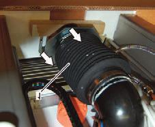
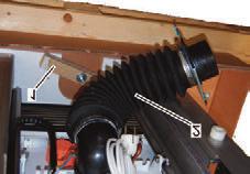
6 2 Lima Lifter To specify the Lima Lifter the following criteria MUST be taken into consideration: Soil Connection The design of the Lima Lifter will only allow connection of the soil through the floor at the base of the Lifting unit. Minimum of 90mm from back wall, any more the unit will stand off the wall. The base of the flexible soil pipe connection extends through the lifter base in readiness to slide in the collar which must be flush with the floor. This is anchored to the lifter base, so when it extends to its full height there is no separation from the floor (as shown in these pictures). Currently the Lifter comes with the two support arms, with no options at present to come without. The unit will require wall and floor fixings at specific points, 1035mm from floor level and 95mm from back wall. There are no clearances behind the unit for any run of pipework ie; waste, continuous feeds etc. Lima Lifter New Back Plate NOTE: Denotes updated machine part different from image shown. 6
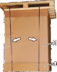


7 Installation Unpacking 3 Installation 3.1 Unpacking the lift system 2 3 7


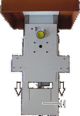
8 Installation Releasing the lift system Releasing the lift system 5 5 * Please see new back plate image on page 6 8

9 Installation Releasing the lift system


10 Installation Releasing the lift system For the fastening of the lift system to the floor, see Fastening the lift system to the floor on page 13/14. 10

11 Installation Fastening the lift system 3.3 Fastening the lift system to the wall The lift system a-butts the wall at the four holes (Fig. 11/arrows) on the rear side of the lift system. See dimension sheet and layout diagram of the lift system in the appendix
 for the lift system.")
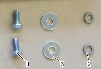
12 Installation Fastening the lift system Using appropriate fittings with washers: insert two on the left and two on the right side of the lift system into the wall holes. Four fastening screws with anchors and washers can be found in the accompanying carton ( Fig. 3/3) for the lift system. 12

13 Installation Fastening the lift system s

.")
 of the anchor dowels (Fig.")
14 Installation Fastening the lift system 6 Using appropriate fixings, insert anchor (Fig. 15/1) in the floor holes (suitable anchor sourced by installer) Tighten the nuts (Fig. 16/arrow) of the anchor dowels (Fig. 15/1) with the correct size wrench in clockwise motion


15 Establishing the connections to the lift system 3.4 Establishing the connections to the lift system Lifter is supplied with a European plug. Where applicable, remove and install appropriate plug for country of origin Water connection is 10mm 19 15


16 Establishing the connections to the lift system louvres 16


17 Establishing the connections to the lift system /


18 Establishing the connections to the lift system


19 Establishing the connections to the lift system louvres 19
.")
20 Installation Mounting the toilet on the lift system 3.5 Mounting the toilet on the lift system 34 (50kg)


. 35 1")
. 37)")
21 Mounting the toilet on the lift system 35) ). 37) 37 21
 on 38 completely, but do not remove it.")
22 Mounting the toilet on the lift system Removing the flush tank housing g. 38) on 38 completely, but do not remove it. 39) Re-insert screw and rubber bung so as to keep safe for re-installation
 and then pull it forward")

23 Mounting the toilet on the lift system 42) upwards (small arrow) and then pull it forward and off (large arrow). 42 Adjuster bracket hooks over the frame (Fig.43). 43: Adjuster bracket 23


.")

24 Mounting the toilet on the lift system 44) outward somewhat (arrows) and pull the lower housing forward (arrow) 47 24


25 Mounting the toilet on the lift system Fig


26 Mounting the toilet on the lift system ) of the lift system by hand Fig. 52: Assembly plate PLEASE NOTE: *Loose wire for flush option only. 26


27 Mounting the toilet on the lift system


28 Mounting the toilet on the lift system


29 Mounting the toilet on the lift system


30 Mounting the toilet on the lift system


31 Mounting the toilet on the lift system


32 Mounting the toilet on the lift system Toilet main cable is supplied with a European plug. This is used to connect the toilet to the lifter. DO NOT REPLACE

33 Performing tests > Testing the flush system for function 3.6 Performing tests Testing the flush system for function Open the water shut-off valve to the lift system on the wall


34 Performing tests > Testing the rinsing system for function 3.6 Performing tests Testing the rinsing system for function : Mains adaptor of the electrical cable

35 Performing tests > Adjusting/regulating the functions of the toilet 3.6 Performing tests Checking the current feed


36 Fitting the covers and mounting the support handles 3.7 Fitting the covers and mounting the support handles ) in from front to : Engaging the side panels of 36

 and into position.")
37 Fitting the covers and mounting the support handles Adjuster bracket hooks over the frame (Fig.79). 79 : Adjuster bracket 80). 80 (arrow) and into position. 81) in from the front 81 37
. 82 83). 83 84).")
38 Fitting the covers and mounting the support handles 82) ) )
.")
39 Fitting the covers and mounting the support handles d The support handle with the lift actuating button and cable must be assembled so that the lift actuating button is positioned to the inside (Fig.87). 87 handles 39


40 Fitting the covers and mounting the support handles 88/ Plates are now adjustable with multi-hole plastic insert


41 Fitting the covers and mounting the support handles


42 Fitting the covers and mounting the support handles 95)


43 Fitting the covers and mounting the support handles 98) of the lift system onto the lift 98 99/1) (arrow). 99: Pulling out the cable


44 Fitting the covers and mounting the support handles ) with six screws (three on the


45 Fitting the covers and mounting the support handles


46 Fitting the covers and mounting the support handles


 1.")


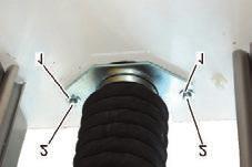
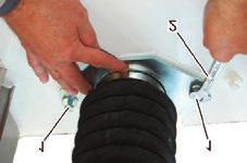
47 Installation of Safety Limiter Installation of safety limiter Before final switch on of the lifter, the Safety Limiter has to be installed beneath the toilet (NOTE: Mount toilet first) 1. Using the screws and washers provided, secure the safety bracket in place as per the sequenced pictures,
48 Checking the lift system for funtion 3.8 Checking the lift system for function Please ensure the safety switch is installed in line with fitting instructions which can be found with the lifting device Checking the lift system for function


49 Checking the lift system for funtion Check for leaks Fig. 113 : Arm flush control option Main power failure battery back-up, supplied as standard. Should the mains power fail battery will allow the unit to be used. Once power has been reconnected battery will re-charge. Continuous use of battery running it completely flat, will result in killing battery, (bleeping when low). Fig. 114: Battery back-up 49


50 Optional Extras Allows the user to operate the wash/dry cycle directly through the lifter controls Fits opposite side to the lift and lower controls (same arm) Needs to have a touch sensitive switch fitted Fig.115 : Blue shower (wash) button Fig.117 : Separate harness connection Separate harness supplied that fit to connection on the lifter Fig.116 : Connection position on lifter Harness then needs to be connected to PCB on the Lima Unit Fig.118 : Harness to board connection 50
51 UK design and development UK manufacturing UK customer support OHSAS Tel: Building 1 Brooklands Place Brooklands Road Sale Cheshire M33 3SD Fax: TH33/June 2017
Infrared Control Valve Installation Guide
 Infrared Control Valve Installation Guide Supplied Parts 1. Sensor Unit 2. Solenoid Valve 3. Mounting Bracket (for cavity walls or ceiling tiles) 4. Remote Valve Plug & Gasket 5. Mounting Screws M3.5 x
Infrared Control Valve Installation Guide
 Infrared Control Valve Installation Guide Supplied Parts 1 1. Sensor Unit 2. Solenoid Valve 3. Mounting Bracket (for cavity walls or ceiling tiles) 2 4. Remote Valve Plug & Gasket 5. Mounting Screws M3.5
Geberit Assisted Toilet Pre-Installation Instructions
 Geberit Assisted Toilet Pre-Installation Instructions Pre-Install Instructions Please see the below for instructions to prepare site for installation. All electrical connections are to be carried out by
Installation, Care and Maintenance Instructions. Optiflush OP1 Battery and OP2 Mains Versions
 Installation, Care and Maintenance Instructions Optiflush OP1 Battery and OP2 Mains Versions The Prestex Optiflush Congratulations on buying the Prestex Optiflush Urinal Flush Controller. The product utilises
Car Battery Charger Instructions for Use
 BATTERY CHARGER 12Volt 4Amp FOR INDOOR USE ONLY Power Details: Input: 230-240Vac; 50Hz; 52W Output: 12V DC; 2.8A Maximum Charge Rate: 4A RMS Read these instructions before operating this car battery charger
Compact Concealed Toilet Cistern with Dual flush CNC1001
 Compact Concealed Toilet Cistern with Dual flush CNC1001 Compact Concealed Toilet Cistern with Dual flush Compact concealed toilet cistern with dual flush can be used with any of the back to wall toilets
Solar Thermal. Grant Solar Pump Station Installation & Servicing Instructions
 Solar Thermal Grant Solar Pump Station Installation & Servicing Instructions Part No. DOC 96. Rev 02. October 2012 Important Note Important Note for Installers The Pump Station supplied with your Grant
HOT WASHER MODEL NO: KING 125 OPERATION & MAINTENANCE INSTRUCTIONS PART NO: LS1009
 HOT WASHER MODEL NO: KING 125 PART NO: 7320170 OPERATION & MAINTENANCE INSTRUCTIONS LS1009 INTRODUCTION Thank you for purchasing this Hot Washer. This machine is a portable, high pressure power washer,
3 litres. 6 litres. Lever Flush Cistern Fittings - Close Coupled / Low Level Cistern 51cm - Close Coupled / Low Level Cistern 44cm
 Lever lush ittings - Close Coupled / Low Level 5cm - Close Coupled / Low Level 44cm All WC s come with a 3/6 litre flush as standard which can be reduced to a.5/4.5 litre flush for the slimline cisterns
Duo water control system
 Duo water control system Installation and maintenance guide DUOINSTRUCT Contents Important and safety information Pack contents / Tools required Duo trim plate dimensions Flow performance Typical wall
HR25 Solo. Installation and User Instructions. Through the Wall Heat Recovery Ventilators
 abc GB HR25 Solo Installation and User Instructions Models:- HR25 Solo HR25 Solo L HR25 Solo H HR25 Solo LH Through the Wall Heat Recovery Ventilators PLEASE READ INSTRUCTIONS IN CONJUNCTION WITH ILLUSTRATIONS.
Urinal Flushing. Hydraulic Valve Infrared Control (IRC) Valve Direct Flush
 Valve Direct Flush") Urinal Flushing Hydraulic Valve Infrared Control (IRC) Valve Direct Flush Hydraulic Valve Urinal flush control valve Reduces water consumption and washroom odours The Hydraulic Valve is an automatic urinal
Urinal Flushing Hydraulic Valve Infrared Control (IRC) Valve Direct Flush Hydraulic Valve Urinal flush control valve Reduces water consumption and washroom odours The Hydraulic Valve is an automatic urinal
INSTALLATION INSTRUCTIONS TOILET. Castello & Sienna Back-to-Wall
 INSTALLATION INSTRUCTIONS TOILET Castello & Sienna Back-to-Wall NOTE: Our Back-to-Wall toilet suites are suitable for both a rear & side entry water inlet. BEFORE YOU BEGIN Before proceeding with installation,
FlushMaster Cistern & Valve assembly
 Installation and operation instructions FlushMaster Cistern & Valve assembly Model 43099NZ - FlushMaster Std. Cistern* and Valve assembly (75mm Body) Model 41096NZ - FlushMaster Cistern Outlet valve 75mm
IRC Urinal Flush Control Valve
 IRC Urinal Flush Control Valve Installation guide Please keep this booklet for future reference. Installer, when you have read these instructions please ensure you leave them with the user. IPAC/15 C-01
ZonePlus Z322 zone valve Installation and commissioning instructions
 ZonePlus Z322 zone valve Installation and commissioning instructions The Z322 mid-position valve has been designed to control the water circulation in fully pumped systems, which employ a single pump for
Installation & Technical Guide. Domestic & Commercial.
 Installation & Technical Guide Domestic & Commercial www.challisbooster.com www.challisboosterplus.com Installation and Technical Guide Domestic and Commercial Challis Water Controls Europower House, Lower
THERMOSTATIC INLINE CONTROL SHOWER VALVES Installation & aftercare instructions
 THERMOSTATIC INLINE CONTROL SHOWER VALVES Installation & aftercare instructions Please retain for future reference DUAL INLINE CONCEALED VALVE SV2204 / SV4404 / SV5504 / SV6604 SV7704 / SV8804 / SV9904
2 PORT MOTORISED VALVE (28 mm)
") 2 PORT MOTORISED VALVE (28 mm) Model No SBMV28 Instruction Manual 2 SBMV28 INSTRUCTION MANUAL PRODUCT COMPLIANCE This product complies with the essential requirements of the following EC Directives: Electro-Magnetic
2 PORT MOTORISED VALVE (28 mm) Model No SBMV28 Instruction Manual 2 SBMV28 INSTRUCTION MANUAL PRODUCT COMPLIANCE This product complies with the essential requirements of the following EC Directives: Electro-Magnetic
HALOGEN FLOODLIGHTS Models CHL1260C & 1260T Part Nos: &
 HALOGEN FLOODLIGHTS Models CHL1260C & 1260T Part Nos: 5460600 & 5460595 OPERATING & MAINTENANCE INSTRUCTIONS GC0610 INTRODUCTION Thank you for purchasing this CLARKE Halogen Floodlight. Before attempting
Versailles Walnut Toilet Seat Versailles Walnut Toilet Seat Soft Close
 Description Versailles High Level Toilet Fired Earth Product Code COMPLEMENTARY PRODUCTS Description Versailles White Toilet Seat Versailles White Toilet Seat Soft Close Versailles Walnut Toilet Seat Versailles
Installation must be in Accordance with AS/NZS
 Installation must be in Accordance with AS/NZS 3500.1. Contents 5 Step Easy Install... 3 Installation Requirements... 3 Cistern Service Access Options... 4 Button Service Access Options... 5 Installing
Your Guide to the Installation, Care and maintenance of PERFORMA. Electronic Self Closing Fittings - Mains Powered 886V (343029) 885V (343027)
 885V (343027)") Your Guide to the Installation, Care and maintenance of PERFORMA Electronic Self Closing Fittings - Mains Powered 886V (343029) 885V (343027) Pegler Limited, St Catherine s Avenue, Doncaster DN4 8DF Telephone
Your Guide to the Installation, Care and maintenance of PERFORMA Electronic Self Closing Fittings - Mains Powered 886V (343029) 885V (343027) Pegler Limited, St Catherine s Avenue, Doncaster DN4 8DF Telephone
MAINTAINED LED CIRCULAR EMERGENCY CEILING LIGHT
 Model No. PEL00588 MAINTAINED LED CIRCULAR EMERGENCY CEILING LIGHT 1 Please read these instructions carefully before starting installation and retain for future reference. The centre page test record can
Warning. Document ref: A October 2015
 Sentry Door Curtain Installation, Operation & Maintainance Instructions Dunham-Bush Ltd, Downley Road, Havant, Hampshire, P09 2JD Tel. 023 9247 7700 Email. info@dunham-bush.co.uk Document ref: 128-000-001-A
Close Coupled/Low Level Cistern 51cm Ceramic lever C1 Close Coupled/Low Level Cistern 51cm Ceramic Front Button C2. 1: Inlet Valve 2: Flush Valve
 Close Coupled/Low Level 5cm Ceramic lever C Close Coupled/Low Level 5cm Ceramic Front Button C : Inlet Valve : Flush Valve 0 Half flush float Should be set on the "" mark 5 4 "" scale Exposed "9" steps
3 PORT MOTORISED VALVE (22 mm)
") Salus SBMV32 (3 port 22mm) Manual.qxd:Layout 1 9/1/11 10:56 Page 1 3 PORT MOTORISED VALVE (22 mm) Model No SBMV32 Instruction Manual Salus SBMV32 (3 port 22mm) Manual.qxd:Layout 1 9/1/11 10:56 Page 2 2
Salus SBMV32 (3 port 22mm) Manual.qxd:Layout 1 9/1/11 10:56 Page 1 3 PORT MOTORISED VALVE (22 mm) Model No SBMV32 Instruction Manual Salus SBMV32 (3 port 22mm) Manual.qxd:Layout 1 9/1/11 10:56 Page 2 2
Sieve Shaker 200mm/300mm - 8/12 inch SV003
 Sieve Shaker 200mm/300mm - 8/12 inch SV003 CONTENTS Introduction Specification Installation Controls Operation Maintenance Spares and Accessories 1 Introduction The unique action of this Sieve Shaker (Fig
SERIES II WALVIT + CUBE. 1.28/0.8 Gal (4.8/3 Litre)
") SERIES II WALVIT + CUBE 1.28/0.8 Gal (4.8/3 Litre) concealed Concealed cistern Tank 237060, 237061 + 237061 237062 & 237062 Contents 5 Step Easy Install... 3 Installation Requirements... 3 Tank Service
SERIES II WALVIT + CUBE 1.28/0.8 Gal (4.8/3 Litre) concealed Concealed cistern Tank 237060, 237061 + 237061 237062 & 237062 Contents 5 Step Easy Install... 3 Installation Requirements... 3 Tank Service
3 PORT MOTORISED VALVE (32/38 mm)
") 3 PORT MOTORISED VALVE (32/38 mm) Model No SBMV32/38 Instruction Manual 2 SBMV32 INSTRUCTION MANUAL PRODUCT COMPLIANCE This product complies with the essential requirements of the following EC Directives:
3 PORT MOTORISED VALVE (32/38 mm) Model No SBMV32/38 Instruction Manual 2 SBMV32 INSTRUCTION MANUAL PRODUCT COMPLIANCE This product complies with the essential requirements of the following EC Directives:
IRC urinal flush control valve
 IRC urinal flush control valve installation guide 1 Introduction the infrared urinal flush control (IRC) valve automatically manages the supply of water to a urinal cistern. On detection of movement in
Chapter 6. Plumbing Elements and Facilities
 AMERICAN NATIONAL STANDARD Chapter 6. Plumbing Elements and Facilities Chapter 6. Plumbing Elements and Facilities 601 General 601.1 Scope. Plumbing elements and facilities required to be accessible by
262CC. Quick Start Guide
 262CC Quick Start Guide Quick Start Guide THE HELM:... 4 LOCATION OF COMPONENTS... 4 ACCESSORY SWITCHBOARD... 4 COMPASS... 4 PLUMBING SYSTEM... 5 FRESHWATER SYSTEM... 5 RAW WATER WASHDOWN... 5 LIVEWELL...
NON MAINTAINED TWIN SPOTLIGHT WALL MOUNT LED EMERGENCY LIGHT
 Model No. PEL00581 NON MAINTAINED TWIN SPOTLIGHT WALL MOUNT LED EMERGENCY LIGHT 1 Please read these instructions carefully before starting installation and retain for future reference. The centre page
VERLLTOIL CLOSE COUPLED WC PAN & CISTERN
 Horizontal bar below rim distinguishes Versailles from former La Rochelle range (on display) Close Coupled Pan & Dual Flush Cistern with White Versailles Seat pictured above 17/11/10 toilet seats for use
Mira Mode Shower and Bath Fittings
 Mira Mode Shower and Bath Fittings Installation Guide Please leave these instructions with the user If you experience any difficulty with the installation or operation of your new shower, then please refer
2 PORT MOTORISED VALVE (22 mm)
") 2 PORT MOTORISED VALVE (22 mm) Model No SPMV22 Instruction Manual 2 SPMV22 INSTRUCTION MANUAL PRODUCT COMPLIANCE This product complies with the essential requirements of the following EC Directives: Electro-Magnetic
2 PORT MOTORISED VALVE (22 mm) Model No SPMV22 Instruction Manual 2 SPMV22 INSTRUCTION MANUAL PRODUCT COMPLIANCE This product complies with the essential requirements of the following EC Directives: Electro-Magnetic
Installation and Operation Instructions
 Installation and Operation Instructions FlushMaster Cistern & Valve Assembly Model 43099 - FlushMaster Std. Cistern* and Valve assembly (75mm Body) Model 41096 - FlushMaster Cistern Outlet valve 75mm dia.
SUBMERSIBLE WATER PUMP
 SUBMERSIBLE WATER PUMP MODEL NO: CSV1A, CSV2A PART NO: 7230582, 7230602 OPERATION & MAINTENANCE INSTRUCTIONS ORIGINAL INSTRUCTIONS 05/14 iss 4 INTRODUCTION Thank you for purchasing this CLARKE Submersible
Lever Flush Cistern Fittings Arcade close coupled cistern ARC5C
 Lever Flush Cistern Fittings rcade close coupled cistern RC5C ll WC s come with a /6 litre flush as standard which can be reduced to a.5/4.5 litre flush for the slimline cisterns On the Close Coupled WC
IMPORTANT INSTRUCTIONS FOR OPERATION & MAINTENANCE OF
 IMPORTANT INSTRUCTIONS FOR OPERATION & MAINTENANCE OF CONVEYORS EASIKIT 300 EASIKIT 450 EASIKIT 600, 900, 1200 & 1500 The manufacturer does not accept responsibility for any loss, damage to other equipment,
Service Manual Gulf Stream Electronic Full Wall Slide Systems
 Service Manual Gulf Stream Electronic Full Wall Slide Systems CONTENTS Page Before you operate the slide system 2 Operating Instructions 3 Preventive maintenance 3 Manually overriding your slide system
C24 C30. Parts supplied: 1: Flush Valve installation
 urlington 50mm close coupled cistern tank with back and bottom entry water supply with lever flush urlington Extended depth 50mm close coupled cistern tank with back and bottom entry water supply with
Standard Valves Series Globe Valves Series Angle Valves Series Way-Valves
 Installation, Operation, Maintenance Instructions Standard Valves Series 035 000 Globe Valves Series 031 000 Angle Valves Series 033 000 3-Way-Valves 1 GENERAL INFORMATION These instructions are designed
THERMOSTATIC CONCENTRIC DUAL CONTROL SHOWER VALVES Installation & aftercare instructions
 THERMOSTATIC CONCENTRIC DUAL CONTROL SHOWER VALVES Installation & aftercare instructions Please retain for future reference EXPOSED CONCENTRIC VALVE SV2201 / SV4401 / SV5501 / SV6601 SV7701 / SV8801 /
Acura TMV3 Bath Filler AC50010CP and AC50020CP
 Acura TMV3 Bath Filler AC50010CP and AC50020CP Installation and Maintenance Instructions In this procedure document we have endeavoured to make the information as accurate as possible. We cannot accept
Key Installation Points. Table of Contents
 Installation Guide Key Installation Points Table of Contents All pipe sizes in this guide are internal diameter (DN) We recommend PE-X pipe NOT copper pipe Check pipes sizes For domestic installations
12 amp RMS Battery Charger
 12 amp RMS Battery Charger 83-5000-12 If faults cannot be remedied, contact the Helpline on 020 8391 6767 helpline@hilka.co.uk Manufactured under license by Hilka Pro Imports GUARANTEE This product is
SUBMERSIBLE WATER PUMP
 SUBMERSIBLE WATER PUMP MODEL NO: CSV1A, CSV2A PART NO: 7230582, 7230602 OPERATION & MAINTENANCE INSTRUCTIONS 0608 INTRODUCTION Thank you for purchasing this CLARKE Submersible Water Pump. This pump is
SHADES TECHNICS T921 TOILET CUBICLE USER MANUAL
 SHADES TECHNICS T921 TOILET CUBICLE USER MANUAL Tel: +44(0)1992 476830 Cat No.746218 Issue 2 31/10/2011 Contents TITLE PAGE Cubicle Operating Instructions 3 Cleaning & Hygiene 5 Daily Maintenance 6 Weekly
MAINTAINED LED EMERGENCY CEILING MOUNT SPOTLIGHT
 Model No. PEL00582 MAINTAINED LED EMERGENCY CEILING MOUNT SPOTLIGHT 1 Please read these instructions carefully before starting installation and retain for future reference. The centre page test record
Adjustable Pneumatic Time Delay Switch
 Adjustable Pneumatic Time Delay Switch Model: DS4 Installation & Operating Instructions 1 1. General Information These instructions should be read carefully and retained for further reference and maintenance.
The Mikrofill Electronic Filling Device. (EFD)
") The Mikrofill Electronic Filling Device. (EFD) The Mikrofill EFD is a fully automatic sealed system filling device, and is suitable for the water management in all domestic and commercial heating and cooling
The Mikrofill Electronic Filling Device. (EFD) The Mikrofill EFD is a fully automatic sealed system filling device, and is suitable for the water management in all domestic and commercial heating and cooling
Instruction Manual UK
 Instruction Manual UK Product: Monterey2 child booster seat Model: 15000 Mfg. by: DIONO Unit D Ventura House Ventura Park Road Tamworth Staffs B78 3LZ UK CUSTOMER SERVICE Tel: 0845.300.9071 Email: dionouk@diono.com
28W WORK LAMP Model: CTL28 Part No:
 28W WORK LAMP Model: CTL28 Part No: 4002905 INSTRUCTION MANUAL GC0609 INTRODUCTION Thank you for purchasing this CLARKE 28W Work Lamp. Before attempting to use the product, it is essential that you read
MANIFOLDS & WATER TEMPERATURE CONTROL
 MANIFOLDS & WATER TEMPERATURE CONTROL Overview Water based underfloor heating (UFH) systems work by turning the entire floor into one large low temperature radiator which is heated via a network of pipes
Rear Bumper Cover Unpainted ( ):
:") Rear Bumper Cover Unpainted (1999-2004): Tools Required: Ratchet Socket extension 7/16 deep well socket 7/16 wrench 5/16 socket Fastener Removal Tool Offset Phillips screwdriver Extendable magnet (optional
Rear Bumper Cover Unpainted (1999-2004): Tools Required: Ratchet Socket extension 7/16 deep well socket 7/16 wrench 5/16 socket Fastener Removal Tool Offset Phillips screwdriver Extendable magnet (optional
Overhead lift Roomer 5200
 USER S MANUAL Overhead lift Roomer 5200 The Roomer 5200 offers you the unique ability to lift and move a patient from one room to another. The lift is equipped with two belts. When transferring from room
CHAPTER 6: PLUMBING ELEMENTS AND FACILITIES
 CHAPTER 6: PLUMBING ELEMENTS AND FACILITIES 601 General 601.1 Scope. The provisions of Chapter 6 shall apply where required by Chapter 2 or where referenced by a requirement in this document. 602 Drinking
INSTALLATION & MAINTENANCE MANUAL HBL
 INSTALLATI & MAINTENANCE MANUAL HBL series 230V 50Hz IP 65 122 1 GENERAL INSTRUCTIS These instructions should be read carefully and retained after installation by the end user for future reference and
Shades Technics. 2050RS Toilet Cubicle. Manual
 Shades Technics 2050RS Toilet Cubicle Manual CONTENTS CUBICLE OPERATING INSTRUCTIONS CLEANING & HYGENE CUBICLE MAINTENANCE WARRANTY CLAIMS SPARE PARTS CATALOGUE Door Sink Vanity Vanity Door Bin Lid Upper
The POWER. In PRESENTATION PRODUCTS. Instruction Book for BOARDROOM ELECTROL DA-LITE SCREEN COMPANY, INC.
 The POWER In PRESENTATION PRODUCTS Instruction Book for BOARDROOM ELECTROL DA-LITE SCREEN COMPANY, INC. 3100 North Detroit Street Post Office Box 137 Warsaw, Indiana 46581-0137 Phone: 574-267-8101 800-622-3737
Bora showers Inline valve cartridge removal instructions. Inline Valve Cartridge Removal Instructions
 Inline valve cartridge removal instructions Inline Valve Cartridge Removal Instructions These instructions provide a guide for removal, replacement and maintenance of the inline valve cartridge. Maintenance
INSTALLATION AND USER INSTRUCTIONS
 INSTALLATION AND USER INSTRUCTIONS Industrial Applications HydroFLOW i Range 45i, 60i, 100i, 120i, 160i Hydropath Holdings Ltd Hydropath House, Unit 7, The Midway Nottingham, NG7 2TS, UK Tel: +44 (0) 115
Installation and Instruction Manual. Cold Weather Starting Aid Part No A. Jet-Ex 4 Diesel Generator Sets
 TO-211 121890 Installation and Instruction Manual for Cold Weather Starting Aid Part No. 489782A For Use With Jet-Ex 4 Diesel Generator Sets HOBART BROTHERS COMPANY Ground Power Division Troy, Ohio 45373
Reverse Polarity MANUAL. Surechlor S3500
 Reverse Polarity MANUAL Surechlor S00 Surechlor S00 MANUAL Contents Installation Cell Power pack Off Peak Installation Connecting the Pool Pump Installation Layout Operation Chlorine Control LED Chlorine
EVAC Commercial Marine Equipment TOILET TECHNICAL DATA EVAC 90, STAINLESS STEEL, FLOOR MODEL, *SHOCK TESTED. Fresh water.
 16 Apr 2009 Doc. 1:141J TECHNICAL DATA 5327002 EVAC 90, STAINLESS STEEL, FLOOR MODEL, *SHOCK TESTED Fresh water connection Shut-off valve Strainer Vacuum breaker 390 Gasket Seat and cover Pneumatic push
Inst all a ti o n and Oper a tin g Instru c ti o n s
 Inst all a ti o n and Oper a tin g Instru c ti o n s Congratulations, you are now the proud owner of an Aqua2use GWDD! INSTALLATION OF PUMP OPERATED AQUA2USE GWDD The Matala Aqua2use GWDD is specifically
Order Number MOP C2. Microwave Oven
 Order Number MOP0107026C2 Microwave Oven 2 2001 Matsushita Electric Industrial Co., Ltd. All rights reserved. Unauthorized copying and distribution is a violation of law. 1 Inverter Warning The inverter
AutoFarm GPS AutoSteer Hardware Installation Guide
 AutoFarm GPS AutoSteer Hardware Installation Guide Supported Models: Deutz 215 Agrotron, 235 Agrotron, 265 Agrotron PN: 602-0047-01-A Special Requirements Tools This list consists of special tools required
Elmdene International Ltd
 1 Elmdene International Ltd Tel: +44(0)23 9269 6638 3 Keel Close, Interchange Park, Fax: +44(0)23 9266 0483 Portsmouth, Hampshire, PO3 5QD, UK Web: www.elmdene.co.uk 13.8Vdc Switch Mode Power Supply GEN3-08-y
Aqua-safe. Waterproof Plug & Socket Connectors Simply better designed
 Aqua-safe Waterproof Plug & Socket Connectors Simply better designed 2 Aqua-safe Simply better designed Elkay s Aqua-safe is the only all-round solution for safely connecting and carrying power through
INSTALLATION AND USER MANUAL
 INSTALLATION AND USER MANUAL SDKIT-730 & SDKIT-734 100% Bolt-On 150 PSI Train Horn System for 2011-2015 F-250 & F-350 Super Duty P/N SDKIT-730 P/N SDKIT-734 Thank you for purchasing a Kleinn Air Horns
Installation Instructions. Vitosol 100. Vitosol 100 Type w 2.5 Flat collector for flat roofs and freestanding installation Part No.
 Installation Instructions Vitosol 100 Type w 2.5 Flat collector for flat roofs and freestanding installation Part No. 3001 970 Vitosol 100 8/99 Safety instructions This hazard symbol precedes all important
Quick and Easy Installation Guide.
 ATTention Quick and Easy Installation Guide. For KingspanWater Envireau Product. 007018 ISSUE 03: MARCH 2011 CC916 DOMESTIC GRAVITY SYSTEM For After Sales Customer Care queries please contact: NI: 028
Installation Instructions
 BAR MIXER BRACKET (compression fit) For Bar Mixers & Bath Shower Mixers 35mm 66mm ¾ BSP 12mm 20mm 39mm Square trim also available Installation Instructions Installers please note these instructions are
Lifting height 5.5" - 72" with adapters " Height overall 165" Width between columns 122" Drive through 109" Width overall 151.
 Model Number TP12KC-D Capacity 12,000 lbs. Lifting height 5.5" - 72" with adapters 79.625" Height overall 165" Width between columns 122" Drive through 109" Width overall 151.125" Arm extension 37.5" -
PSX2 (Power Stabilizing System) OEM INSTALLATION MANUAL
 OEM INSTALLATION MANUAL") PSX2 (Power Stabilizing System) OEM INSTLLTION MNUL Rev: 10.24.2018 PSX2 OEM TLE OF CONTENTS Safety Information 2 System Description 3 Installation 3 Resources Required 3 Determine Stabilizer Locations
PSX2 (Power Stabilizing System) OEM INSTLLTION MNUL Rev: 10.24.2018 PSX2 OEM TLE OF CONTENTS Safety Information 2 System Description 3 Installation 3 Resources Required 3 Determine Stabilizer Locations
Operating & Installation Manual
 Operating & Installation Manual (ZH1.5kw wind turbine system) Company Name:YUEQING ZONHAN WINDPOWER CO.,LTD. Address:NO.195,Chengxi Road,Yuecheng,Yueqing,Zhejiang,P.R.China Zip Code:325600 Tel:86-577-62529820
BBT006/ BBC006/ BBCD006 TOYOTA LANDCRUISER 100 SERIES IFS
 INSTALLATION GUIDE BBT006/ BBC006/ BBCD006 TOYOTA LANDCRUISER 100 SERIES IFS Ironman 4x4 BBT/ BBC/ BBCD006 Bull Bars fit to a Toyota Landcruiser 100 Series (IFS). It will take about 2 hours to install.
Installation Manual for D154X Series Multi-Indicator, General Purpose Power Supplies
 Installation Manual for D154X Series Multi-Indicator, General Purpose Power Supplies D1541 D1542 D1543 D1545 D1543-X-8 D1545-X-8 D1545-4BNC D154X Series 1A 2A 3A 5A 3A fitted with 8-way output splitter
1.Safe testing IMPORTANT:
 Electricity is dangerous and can cause injury and death. Always treat it with the greatest of respect and care. If you are not quite sure how to proceed, then stop, take advice from a qualified person.
M T E C o r p o r a t i o n. dv/dt Filter. Series A VAC USER MANUAL PART NO. INSTR REL MTE Corporation
 M T E C o r p o r a t i o n dv/dt Filter Series A 440-600 VAC USER MANUAL PART NO. INSTR - 019 REL. 041119 2004 MTE Corporation IMPORTANT USER INFORMATION NOTICE The MTE Corporation dv/dt Filter is designed
FITTING INSTRUCTIONS
 FITTING INSTRUCTIONS All Zero 360 FIA Systems PLEASE READ CAREFULLY BEFORE ATTEMPTING TO INSTALL YOUR SYSTEM Lifeline Fire & Safety Systems Ltd 008 Thank you for purchasing a FIA approved Zero 360 Lifeline
BBT029/ BBC029/ BBCD029 TOYOTA PRADO 150. Ironman 4x4 BBT/ BBC/ BBCD029 Bull Bars fit to a Toyota Prado 150. It will take about 3 hours to install.
 INSTALLATION GUIDE BBT029/ BBC029/ BBCD029 TOYOTA PRADO 150 Ironman 4x4 BBT/ BBC/ BBCD029 Bull Bars fit to a Toyota Prado 150. It will take about 3 hours to install. NOTE: This product has been tested
Flue installation instructions. Air flue duct for use with ecomax and ecotec boilers. For the installer
 834449_05GB_022005.qd 02.02.2005 17:12 Uhr Seite 1 For the installer Flue installation instructions Air flue duct for use with ecomax and ecotec boilers ecomax 613/2 E ecomax 618/2 E ecomax 622/2 E ecomax
AutoFarm GPS AutoSteer Hardware Installation Guide
 AutoFarm GPS AutoSteer Hardware Installation Guide Supported Models: Deutz 130 Agrotron, 140 Agrotron, 150 Agrotron, 165 Agrotron PN: 602-0046-01-A Special Requirements Tools This list consists of special
TOYOTA YARIS HATCHBACK INTERIOR LIGHT UPGRADE Preparation
 Preparation Part Number PTS21-52062-08 NOTE: Part number of this accessory may not be the same as the part number show Kit Contents Item # Quantity Reqd. Description 1 1 12 Light Guide 2 1 7 Light Guide
LEAK TEST PROCEDURE MRTALPCH611LDC REMOTE READY LIFTERS W/ 3 BUTTON CONTROL APPLICABLE TO LIFTERS WITH SERIAL NUMBERS GREATER THAN #
 LEAK TEST PROCEDURE MRTALPCH611LDC REMOTE READY LIFTERS W/ 3 BUTTON CONTROL APPLICABLE TO LIFTERS WITH SERIAL NUMBERS GREATER THAN # 20100742 TESTING AND MAINTENANCE MUST BE DONE BY A QUALIFIED PERSON
YARIS 4-DOOR 2007 INTERIOR LIGHT UPGRADE
 Document # 3999 4/26/06 4-DOOR 2007 INTERIOR LIGHT UPGRADE Preparation Part Number: 00016-52060 Code: IL1 Kit Contents Item # Quantity Reqd. Description 1 1 12 Light Guide 2 1 7 Light Guide 3 1 Hardware
Instruction manual. Liftkar HD Uni Liftkar HD Fold Liftkar HD Dolly Liftkar HD Fold Dolly. Issued: 10/2010 subject to updates.
 Instruction manual Liftkar HD Uni Liftkar HD Fold Liftkar HD Dolly Liftkar HD Fold Dolly Issued: 10/2010 subject to updates. en Contents 1 INTRODUCTION AND KEY FEATURES... 3 1.1. General safety guidelines...
3.1 DISPENSER BLACK SHADOW SERIES. Tools Needed for Mounting SCS Dispenser Hammer
 SCS 2 BLACK SHADOW SERIES 3.1 DISPENSER ALWAYS OBSERVE PRODUCT SAFETY AND HANDLING INSTRUCTIONS. ALWAYS DIRECT DISCHARGE AWAY FROM YOU or other persons. ALWAYS DISPENSE CLEANERS AND CHEMICALS AS DIRECTED
1100W PORTABLE GENERATOR
 1100W PORTABLE GENERATOR MODEL NO: G1200 PART NO: 8010110 OPERATION & MAINTENANCE INSTRUCTIONS LS0312 INTRODUCTION Thank you for purchasing this CLARKE 1100W Portable Generator. Before attempting to use
Installing instruction Power-restraining FB33 March 2005
 Installing ROLTEC restraining system for vehicles, model FB33 for ROLTEC Vision electric wheelchair Table of contents General - - - - - - - - - - - - - - - - - - - - - - - - - - page 1 Included in the
INSTALLATION INSTRUCTIONS
 INSTALLATION INSTRUCTIONS Optional central heating time clocks for Vaillant Combination boilers: TURBOmax VUW 4/ E, VUW 8/ E ECOmax VUW 6 E, VUW 86 E ECOmax 84 E, 88 E 4 hour time clock Art. No. 00 880
Ocelot vertical fan coil unit
 Ocelot vertical fan coil unit 250mm Deep vertical Waterside control Cased unit DUNHAM BUSH OCELOT VERTICAL CASED FAN COIL UNIT The Dunham Bush Ocelot fan coil unit is a fully cased vertical unit suitable
Installation Instructions
 2011-2013 LML DURAMAX COMPOUND-ADD 2011-2015 LML A Duramax TURBO KIT Add INSTALL A Turbo INSTRUCTIONS Compound Kit Installation Instructions 1-800-955-0476 - www.industrialinjection.com - info@industrialinjection.com
WALKIE HIGH LIFT HYDRAULIC SYSTEM
 WALKIE HIGH LIFT HYDRAULIC SYSTEM W30-40ZA [B453]; W20-30ZR [B455]; W25-30-40ZC [B454] PART NO. 1524251 2000 SRM 1025 SAFETY PRECAUTIONS MAINTENANCE AND REPAIR When lifting parts or assemblies, make sure
SUBMERSIBLE WATER PUMPS
 SUBMERSIBLE WATER PUMPS Model Nos. CS85S - CS85SA CS120S - CS120SA CS185S - CS185SA CS240S - CS240SA CS305S - CS305SA OPERATING & MAINTENANCE INSTRUCTIONS 1000 CONTENTS Warranty conditions... 3 Safety
I-317. AWWA Check Valves WARNING INSTALLATION AND MAINTENANCE INSTRUCTIONS SERIES 317 WARNING
 Read and understand all instructions before attempting to install, remove, adjust, or perform maintenance on any Victaulic piping products Wear safety glasses, hardhat, and foot protection. Failure to