O p e r a t o r ' s M a n u a l
|
|
|
- Buck Griffin
- 5 years ago
- Views:
Transcription

1 Operator's Manual
2
3 Ipump Pain Management System Operator s Manual Appendix A Product Code: 2L3107 2L3107K Software Versions: Note: Before operating this pump, the user should carefully read this manual to fully understand how the pump functions and to ensure its safe and proper operation. Ipump Pain Management System Operator s Manual i CD07-19-E4-766
4 Notice There are risks associated with using anything other than the recommended sets with this device. Sets designated for use with this device are listed in Accessories, Disposables, and Recommended Sets, 8-1. Baxter s warranty on this device will be null and void, and Baxter will assume no responsibility for incidents that may occur if the product is not used in accordance with product labeling. Computer Software Copyrights Copyright , Baxter Healthcare Corporation. All rights reserved. For use only by Baxter Healthcare Corporation. The software contains proprietary information belonging to Baxter Healthcare Corporation. The software must not be reproduced or disclosed to others without prior written approval. Any unauthorized use of this information may subject the user to substantial liability. Documentation Copyrights Duplication or distribution of this manual and any information contained within is strictly prohibited without the express written permission of Baxter. This manual and any information contained within may not be reproduced, distributed, or transmitted in any form, or by any means, for any purpose without the express written permission of Baxter. Ipump Pain Management System Operator s Manual ii CD07-19-E4-766
5 Disclaimer The information in this document has been carefully examined and is believed to be entirely reliable. However, no responsibility is assumed for inaccuracies. Furthermore, Baxter reserves the right to make changes without notice to any products herein to improve readability, function, or design. Baxter does not assume any liability arising out of the application or use of any product or circuit described herein; neither does it cover any license under its patent rights nor the rights of others. Trademark Information Baxter, the Baxter wordmark, Ipump, Viaflex, and IntraVia are trademarks of Baxter International Inc. TOR and Hi-TOR are trademarks of Huntington Professional Products. LpH and Septisol are trademarks of STERIS Corporation. Super-Edisonite is a trademark of Colgate-Palmolive Co. Other product names appearing in this manual are the property of their respective owners. Year 2000 Compliance This product has been designed for Year 2000 compliance. Roll over between all significant time demarcations (for example, days, months, years, centuries), special dates, and leap years, will be performed correctly. Neither the performance nor the functionality is affected by dates prior to, during and after the year 2000 up to the year Ipump Pain Management System Operator s Manual iii CD07-19-E4-766
6 Warranty Baxter warrants that the equipment shall be free from defects in materials and workmanship when delivered to the original purchaser. Baxter s sole obligation shall be to repair or replace the product (excluding batteries), at Baxter s option and expense, for a period of one year following the date of initial delivery. This warranty extends only to the original purchaser, is not assignable or transferable, and shall not apply to auxiliary equipment or disposable accessories. There are risks associated with using anything other than the recommended Baxter sets designated for use with the Ipump Pain Management System. Baxter s warranty to repair or replace the product will be null and void if this product is used contrary to the directions for use contained in the labeling. Baxter will assume no responsibility for incidents that may occur if the product is not used in accordance with product labeling. THERE ARE NO OTHER WARRANTIES INCLUDING ANY IMPLIED WARRANTY AND ANY WARRANTY OF MERCHANTABILITY OR FITNESS FOR A PARTICULAR PURPOSE WHICH EXTEND BEYOND THE DESCRIPTION OF THE PRODUCT AND THOSE EXPRESSLY SET FORTH IN ITS LABELING. In no event shall Baxter be responsible for incidental, consequential, or exemplary damages. Modification, alteration, recalibration, or abuse, and service by other than a Baxter authorized representative may void the warranty. Ipump Pain Management System Operator s Manual iv CD07-19-E4-766
7 Meaning of the CE Mark Symbol 0123 This symbol represents adherence to Medical Device Directive (MDD) 93/42/EEC. The electromagnetic compatibility (EMC) requirements are part of the essential requirements of the MDD. Device: Ipump Pain Management System Catalog Number: Manufacturer: Authorized representative: xxxxx REF 2L3107K Manufactured by an affiliate of: Baxter Healthcare Corporation Deerfield, IL USA Made in Singapore Baxter S.A. B-7860 Lessines, Belgium EC REP Ipump Pain Management System Operator s Manual v CD07-19-E4-766
8 Ipump Pain Management System Operator s Manual vi CD07-19-E4-766
9 Contents Meaning of the CE Mark Symbol... Chapter 1. Product Overview Key Features Programming Options Record Management Security Organization of This Manual Safety Summary General Information Serial Number Format Label Symbol Definitions Definitions Warnings Cautions Notes v Ipump Pain Management System Operator s Manual vii CD07-19-E4-766
10 Chapter 2. Chapter 3. Ipump Pain Management System Description Ipump Pain Management System Package Contents Pump Components Pump Key Pad Action Keys Pump Symbols LCD Symbols Setting Up the Pump Installing and Changing the Battery Install the 9-volt Alkaline Battery Change the Battery Connecting the AC Adapter Connecting the PCA Cord Unlocking and Opening the Cover Removing or Changing the Cover Preparing, Loading, and Changing the Tubing Set and Fluid Bag Loading the Tubing Set Filling and Loading the Fluid Bag Ipump Pain Management System Operator s Manual viii CD07-19-E4-766
11 Chapter 4. Chapter 5. Changing the Tubing Set and/or Fluid Bag Attaching or Removing the Pump From a Pole (Optional) Attach the Pump to a Pole Remove the Pump from the Pole Configurable Options Using the Pump Preliminary Information Select Settings and Enter Values Turn on the Back Light Retain Programming Data Display the Power Status Basic Pump Procedures Turn On the Pump Turn Off the Pump Select the Language Accept or Modify Date and Time Settings Unlock and Lock the Cover Enter the Security Code Ipump Pain Management System Operator s Manual ix CD07-19-E4-766
12 Use the Initial Prescription Select the Mode and Units Set the Concentration Set the Fluid Volume in the Bag Prime the Tubing Set Upstream Occlusion Testing Programming the Prescription Programming the PCA Dose Setting the PCA Delay Period Programming the Basal Rate Setting the Dose Limit Programming the Continuous Rate Programming the Bolus Dose Programming a Supplemental (Clinician) Bolus Starting, Stopping, Restarting the Infusion Starting the Infusion Stopping the Infusion (Sleep Mode Option) Ipump Pain Management System Operator s Manual x CD07-19-E4-766
13 Chapter 6. Chapter 7. Restarting the Infusion Changing the Prescription During Infusion Reviewing the Therapy History Review the Prescription Navigating Through Patient History View a Patient s History History Not Available Message Optional History Printout Alerts and Alarms Alerts Alarms Preventive Maintenance Authorized Service Centers Cleaning the Pump Cleaning the Carrying Case Preventive Maintenance Checklist Transporting and Storing the Pump Repair and Troubleshooting Ipump Pain Management System Operator s Manual xi CD07-19-E4-766
14 Chapter 8. Chapter 9. Chapter 10. Accessories, Disposables, and Recommended Sets Technical Specifications Technical Specifications Recommended Practices Flow Rate Accuracy of the System Startup Graph Description How Trumpet Graphs are Interpreted How Trumpet Graphs are Created How Trumpet Graphs Can be Used Startup and Trumpet Graphs at 0.1 ml/hr Startup and Trumpet Graphs at 3.0 ml/hr List of Materials Electromagnetic Compatibility Statement Glossary Index Ipump Pain Management System Operator s Manual xii CD07-19-E4-766
15 Chapter 1. Product Overview The Ipump Pain Management System (hereafter referred to as the pump ) is indicated for the controlled delivery (continuous, intermittent, and continuous plus intermittent) of analgesic, sedative, and anesthetic solutions through clinically acceptable routes of administration including intravenous, subcutaneous, and epidural, and for regional (local) analgesia applications. This lightweight, compact pump can be battery operated for portability or connected to an AC power source for stationary use. A specially designed optional locking pole-mounting clamp allows the pump to be attached to a standard IV pole. With the pole clamp removed, the pump can be placed into a comfortable carrying case. Key Features The pump s key features include: Air sensor Preventive maintenance alert Multilanguage interface Detailed history display and printout capability Ability to transfer configuration data via a serial port to another pump Upstream and downstream occlusion detectors Programmable limits for Patient Controlled Analgesia (PCA) doses Ipump Pain Management System Operator s Manual 1-1 CD07-19-E4-766
16 Programming Options The pump can be programmed to provide: PCA, Basal and PCA (Basal+PCA), or Continuous infusions Infusion rates in ml, mg, and μg Physician-prescribed values for the desired therapy Clinician- or institution-selected operating limits When the pump is programmed for PCA, the patient has the option of self-administering analgesic medications on an as-needed basis. The Basal+PCA programming option combines this patient-controlled method with a minimum continuous dose. Record Management The pump tracks the programming, time, and history of each infusion. All of this data is retained in the memory of the pump s microprocessor when the pump is off. The pump is equipped with a real-time clock that provides the correct date and time for record management. The date and time are displayed on the screen and included on any printouts generated by using the optional printer. Ipump Pain Management System Operator s Manual 1-2 CD07-19-E4-766
17 Security For patient security, the pump may be configured to require the: Insertion of a key in the cover lock (KEY ONLY) Entry of a security code before programming or changing the prescription (CODE ONLY) Both key insertion and code entry (KEY+CODE) the factory default configuration Note: If the pump is configured to require only the entry of a security code, the cover that holds the IV bag is optional. Note: Use of security features, such as KEY+CODE, should be governed by individual care site policies and regulations regarding the use of controlled substances. Organization of This Manual This manual is designed for use by trained health care professionals.! WARNING! This manual is intended for clinicians only. Do not permit patients to have access to this manual. Do not disclose the pump's security codes to patients. Ipump Pain Management System Operator s Manual 1-3 CD07-19-E4-766
18 The chapters of this manual provide the following information: Chapter 2 Ipump Pain Management System Description covers what is included in the shipping package and the components of the pump. Chapter 3 Setting Up the Pump describes how to install the pump battery, load and prepare the tubing set, mount the pump on a pole, set up connections, and remove the cover. Chapter 4 Configurable Options lists the factory-set options and how to reset these values. Chapter 5 Using the Pump contains step-by-step instructions for setting up prescriptions, starting and stopping infusions, and accessing and reviewing a patient s prescription history. Chapter 6 Alerts and Alarms provides an alphanumeric list of the alert and alarm messages that may occur and how to resolve them. Chapter 7 Preventive Maintenance contains references on conducting functional checks and storage procedures and authorized service center contacts. Chapter 8 Accessories, Disposables, and Recommended Sets contains a list of accessories, including bags and sets, that can be used with the pump. Chapter 9 Technical Specifications contains a list of the pump s physical and operational specifications. Chapter 10 Electromagnetic Compatibility Statement identifies the EMC standards to which the pump was subjected, the test levels and levels met, and general EMC guidance. A Glossary and an Index are included to assist in using the pump and this manual. Ipump Pain Management System Operator s Manual 1-4 CD07-19-E4-766
19 Safety Summary General Information Although the pump has been designed and manufactured to exacting specifications, it is not intended to replace trained personnel in the supervision of pain management infusions. This product is classified by Underwriters Laboratories Inc. with respect to electric shock, fire, and mechanical hazards only in accordance with UL (UL ), Second edition, and CAN/CSA C22.2 No In accordance with these documents, and in accordance with international standard IEC ( ) Medical Electrical Equipment Part 1: General Requirements for Safety, the pump is classified as: Class II, internally powered Type CF Drip-proof (IPX1) Not suitable for use with flammable anesthetic mixtures with air, oxygen, or nitrous oxide Continuous operation Ipump Pain Management System Operator s Manual 1-5 CD07-19-E4-766
20 Before operating this pump, the user should carefully read this manual to understand fully how the pump functions and to ensure its safe and proper operation. This manual has been developed with consideration of the requirements in the Collateral Standard IEC , First Edition , Medical Electrical Equipment, Part 2-24: Particular Requirements for the Safety of Infusion Pumps and Controllers. When disposing of this device or the sets designed for use with the device, follow local regulations and guidelines. Serial Number Format Year of Manufacture (11 = 2001, 9 = 1999) Month of Manufacture SN AL Sequential Number Product Identifier Ipump Pain Management System Operator s Manual 1-6 CD07-19-E4-766
21 Label Symbol Definitions Label IPX1 Description Drip-proof equipment: enclosed equipment protected against dripping fluids. Connection port for the AC to DC converter/adapter. 5R78 MEDICAL EQUIPMENT UL CAN/CSA C22.2 No This product is classified by Underwriters Laboratories Inc. with respect to electric shock, fire, and mechanical hazards only in accordance with UL (UL ), Second edition, and CAN/CSA C22.2 No The symbol of conformity to the Council directive 93/42/EEC. EU Authorized Representative: Baxter S.A. B-7860 Lessines, Belgium CAUTION, Consult Accompanying Documents (Read the operator s manual for complete instructions before using this device.) Type CF applied part. * * The "Type CF Applied Part" symbol indicates the level of electric shock protection for the patient-contacting parts such as the PCA button and the IV set. UL/EN defines Type CF as providing greater protection than Type B or Type BF. Ipump Pain Management System Operator s Manual 1-7 CD07-19-E4-766
22 Electrostatic Sensitive Devices (The pins of the PRINTER/COMM connector are subject to Electrostatic Discharge and should not be touched. Refer to page 10-7 for additional information.) Symbol (WEEE 2002/96/EC) Crossed-out wheeled bin For product disposal, ensure the following: Do not dispose of this product as unsorted municipal waste. Collect this product separately. Use collection and return systems available to you. Bar below bin Product distributed after August 13, For more information on return, recovery, or recycling of this product, please contact your local Baxter representative. Manufacturer EC REP Authorized Representative in the European Community REF SN Catalog Number Serial Number Ipump Pain Management System Operator s Manual 1-8 CD07-19-E4-766
23 Definitions The safety and information labels included in this manual are defined as follows: Warning messages indicate a possible hazard that, if not avoided, could result in severe personal injury or death. Caution messages indicate a problem or unsafe practice that, if not avoided, could result in minor or moderate personal injury or product or property damage. Note messages provide information that supplements the accompanying text. Warnings! WARNING!! WARNING!! WARNING!! WARNING! This manual is intended for clinicians only. Do not permit patients to have access to this manual. Do not disclose the pump's security codes to patients. The pump has been configured with factory defaults. Please verify the appropriateness of the pump configuration for your institution prior to initial use. See "Configurable Options," 4-1, for more details. Baxter will assume no responsibility for incidents that may occur if the product is not used in accordance with product labeling. Always read and follow the instructions which accompany the source container and the administration sets you are using. Carefully follow any label copy instructions for loading, removing, and reloading the set, as well as the recommended set change interval. For optimal pump performance, set use should not exceed the change interval shown on the set's label copy or 72 hours, whichever is less. Ipump Pain Management System Operator s Manual 1-9 CD07-19-E4-766
24 ! WARNING!! WARNING!! WARNING!! WARNING!! WARNING!! WARNING!! WARNING! For infection control purposes, consider the set change interval recommended by the United States Centers for Disease Control and Prevention (CDC), your institution's guidelines, and the instructions provided with the administration set, using whichever is most appropriate. Only use sets manufactured by Baxter as specified in Accessories, Disposables, and Recommended Sets, 8-1. To reduce the risk of stored fluid being infused after a downstream occlusion occurs, relieve the pressure by disconnecting the system above the occlusion before freeing the occlusion. The tubing set MUST NOT be connected to the patient while priming. When the Upstream Occlusion Detection feature is enabled, and the automatic upstream occlusion test is performed, the pump may withdraw up to 0.03 ml of fluid and subsequently deliver up to 0.09 ml of fluid at the end of the test period. If these volumes are clinically significant for the patient, please take appropriate measures. See "Upstream Occlusion Testing," 5-18, for more details. When infusing at low flow rates (less than 0.5 ml/hr), the pump may not detect air in the tubing. In addition, when infusing at low flow rates (less than 0.5 ml/hr), and there is an upstream occlusion, it is possible for the pumping mechanism to pull air through the tubing wall and into the fluid path of the set. For infusion routes where air in tubing may be clinically significant for the patient, Baxter strongly recommends the use of administration sets containing an air eliminating filter. See "Accessories, Disposables, and Recommended Sets," 8-1, for a list of air eliminating administration sets available for this pump. Clamp tubing distal to the pump before opening the tubing door or troubleshooting any pump connected to a patient. Ipump Pain Management System Operator s Manual 1-10 CD07-19-E4-766
25 ! WARNING!! WARNING!! WARNING!! WARNING!! WARNING! Do not use in the presence of flammable anesthetics. Epidural administration of drugs other than those indicated for epidural use could result in serious injury to the patient. Epidural administration of anesthetics is limited to short-term infusion (not to exceed 96 hours) with indwelling catheters specifically indicated for short-term anesthetic epidural drug delivery. Epidural administration of analgesics is limited to use with indwelling catheters specifically indicated for analgesic epidural delivery. To prevent the infusion of drugs not indicated for epidural use, do not use IV administration sets incorporating injection sites during epidural delivery. It is strongly recommended that the pumps programmed for epidural drug delivery be clearly differentiated from those programmed for other routes of administration. Hospital protocol for the management of high alert medications must be followed with this device. To help prevent medication errors, Baxter recommends that both the clinician programming the pump and another clinician check the accuracy of prescription and programming information before the infusion is started. Hospital and nursing protocols for the prescription and delivery of narcotic analgesic drugs, including the education, monitoring, and care of patients receiving such drugs, must be followed when dispensing narcotic analgesic drugs to patients using this device. Ipump Pain Management System Operator s Manual 1-11 CD07-19-E4-766
26 ! WARNING!! WARNING!! WARNING!! WARNING!! WARNING! Patients receiving narcotic analgesic drugs with any patient-controlled analgesia (PCA) pump should be instructed in the proper use of the device. Instructions should include that only the patient or a licensed healthcare practitioner may operate the PCA button, unless the prescribing physician authorizes a lay caregiver to do so. Without physician authorization, operation of the device by all other persons is prohibited. When using this pump, periodic patient monitoring must be performed to ensure that the infusion is proceeding as expected. The pump is capable of developing positive fluid pressures to overcome widely varying resistances to flow such as resistance imposed by small-gauge catheters, filters, or intra-arterial infusion. The pump is designed to stop fluid flow when an alarm occurs, but it is neither designed nor intended to detect infiltrations and will not alarm under infiltration conditions. This pump should be used only with the Baxter accessories specified for it. There are risks associated with using anything other than the recommended accessories with this pump. Accessories designated for use with this pump are listed in Accessories, Disposables, and Recommended Sets, 8-1. The pump has not been tested for use in the vicinity of magnetic resonance imaging (MRI) equipment or ESU equipment. The pump may malfunction and cease to operate. To avoid personal injury, ensure that the IV pole is stable and secure. Ensure that the pole can support the pump, along with any other devices, without tipping or falling. The pole diameter should be between 1.3 and 3.2 cm (0.5 and 1.25 inches). Ipump Pain Management System Operator s Manual 1-12 CD07-19-E4-766
27 Cautions CAUTION CAUTION CAUTION CAUTION CAUTION CAUTION CAUTION CAUTION In the US, use of this pump is restricted to sale or use by, on the order of, or under the supervision of a qualified physician. There are no internal user serviceable parts or adjustments. When using the optional AC adapter, use earth-grounded AC outlets only. When grounding reliability is in doubt, the equipment should be powered by its battery. Variations in epidural catheter sizes can cause downstream occlusion alarms. If an occlusion alarm occurs with no visible occlusion, change to a larger diameter and/or shorter catheter. If occlusion alarms continue, contact your nearest authorized service center. Do not use sharp objects to press keys. The time to detect occlusions increases proportionally with a decrease in flow rates. At flow rates below 0.5 ml/hr, an occlusion may not be detected. Baxter recommends that extra care be taken to ensure that neither the tubing nor the bag are pinched, twisted, or occluded. The pump can be configured with the upstream occlusion detection disabled. If this feature is disabled, Baxter recommends that extra care be taken to ensure that neither the tubing nor the bag are pinched, twisted, or occluded. This pump has configurable options. Operating modes and input parameter selections may vary as a function of the selected configuration. Ipump Pain Management System Operator s Manual 1-13 CD07-19-E4-766
28 CAUTION CAUTION CAUTION CAUTION CAUTION As with all medical electronic equipment, exercise care to avoid exposing this pump to powerful sources of electromagnetic interference. This device design has been tested to current U.S. and European standards and guidelines for medical devices. The pump was not found to be affected adversely by these susceptibility tests and will perform safely. The pump s emissions also were found to be acceptable. Using the pump near operating equipment that radiate high-energy radio frequencies (such as electrosurgical/cauterizing equipment, two-way radios, or cellular telephones) may cause false alarm conditions. If this happens, reposition the pump away from the source of interference or turn off the pump. Use only accessory equipment complying with the pump s safety requirements; failure to do so may lead to reduced safety levels of the resulting system. Consideration relating to accessory choice shall also include the use of the accessory in the patient vicinity, and evidence that the safety certification of the accessory has been performed in accordance with the appropriate UL (UL ) or IEC and/or IEC harmonized national standard. Use this product for its intended use as described in this manual. Do not use attachments not recommended by the manufacturer. If interconnection with other infusion systems and/or parallel infusion is desired, make sure a recommended Anti-Reflux Y-Site Extension Set (2L3506) or a set containing an integral Y-Site (2L3525, 2L3526, or 2L3527) is used to prevent back flow. Follow the cleaning schedule and methods defined in Preventive Maintenance, 7-1, to ensure the proper maintenance of the pump. Any equipment connected to the pump through the PRINTER/COMM port must conform to the electrical safety requirements of IEC Ipump Pain Management System Operator s Manual 1-14 CD07-19-E4-766
29 CAUTION CAUTION When attaching the pump to an IV pole, ensure that it has been clamped securely. If the pump is attached to an IV pole, ensure that the device is mounted where the main body is easily accessible and the IV administration set can be installed in the loading mechanism without stretching or kinking the tubing. Notes Note: In the US, grounding reliability can be achieved only when this equipment is connected to an earth-grounded receptacle marked Hospital Grade. When grounding reliability is in doubt, the equipment should be battery powered. Note: The pump may be configured to the specific needs of the operator or institution. See the Ipump Pain Management System Global Configuration Manual for further information. Note: Baxter requests that parties acquiring this device: Promptly report receipt of this device to Baxter. Report the device's purchase, receipt in trade, return after sale, loss, destruction, or retirement. If this is an initial purchase from Baxter, returning a signed copy of the packing list to Baxter will fulfill this request. Contact your local Baxter service facility for additional information. Note: No natural latex was used in the manufacture of this pump. Ipump Pain Management System Operator s Manual 1-15 CD07-19-E4-766
30 Ipump Pain Management System Operator s Manual 1-16 CD07-19-E4-766
31 Chapter 2. Ipump Pain Management System Description This section will acquaint you with the various components of the pump, including the: Ipump Pain Management System Package Contents Pump Components Pump Key Pad Action Keys Pump Symbols LCD Symbols Ipump Pain Management System Operator s Manual 2-1 CD07-19-E4-766
32 Ipump Pain Management System Package Contents When the pump arrives, check to make sure that you have all the required parts, which should include the: Ipump Pain Management System 250E Cover Key(s) PCA Cord and Button Pump Carrying Case Operator s Manual(s) Configuration Manual If you need to connect the pump to an electrical power source, you will also need a Baxter AC adapter, which is sold separately. (See Accessories, Disposables, and Recommended Sets, 8-1.) Ipump Pain Management System Operator s Manual 2-2 CD07-19-E4-766
33 250E Cover Carrying Case Key Ipump Pain Management System Figure 2-1 Ipump Pain Management System Package PCA Cord and Button Ipump Pain Management System Operator s Manual 2-3 CD07-19-E4-766
34 Pump Components The pump is a linear peristaltic pump that consists of a: Key pad for programming Container (cover) that holds the fluid bag in place and can be locked Tubing door that holds the tubing in place and protects it Battery compartment to hold the battery AC Power port Printer port PCA port Ipump Pain Management System Operator s Manual 2-4 CD07-19-E4-766
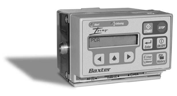
35 Pump Key Pad Liquid Crystal Display (LCD) Start, Stop Enter, On/Off Clear/Silence, History Left, Scroll, and Right Arrow Keys Retaining Clip Figure 2-2 Pump Key Pad Note: When operating on battery power only, after a period of inactivity the back light and key pad are deactivated to save energy. Press any key other than the START key once to reactivate the back light and key pad, then press the desired action key(s). Ipump Pain Management System Operator s Manual 2-5 CD07-19-E4-766
36 Action Keys Table 2-1 Action Keys Action Key Description The ON/OFF key powers up and powers down the pump. Press this key once to power on the pump. Press this key twice to power off the pump. For more detailed information, see Turn On the Pump, 5-5, and Turn Off the Pump, 5-6. The left ( ) and right ( ) arrow keys move the cursor ( ) on the LCD to the left and right. The scroll ( ) key displays the next available option or scrolls through the digits 0-9 at the cursor s ( ) current position on the LCD. Press and hold the key to increase the scrolling speed. The Enter key sets the value displayed on the LCD. Ipump Pain Management System Operator s Manual 2-6 CD07-19-E4-766
37 Table 2-1 Action Keys continued Action Key Description The START key begins the operation of the pump and can also be configured to act as a PCA button. If all of the required programming values have been entered, the START key initiates the infusion. Following the resolution of certain alerts or alarms, pressing the START key resumes the infusion if the condition no longer exists. The STOP key must be pressed twice in 1 second to stop the operation of the pump. After you press the STOP key, you can press the ON/OFF key to turn the pump off. The History key displays the infusion history on the LCD. The Clear/Silence key either clears the data shown on the LCD or silences an alert or alarm signal generated by the pump. Ipump Pain Management System Operator s Manual 2-7 CD07-19-E4-766
38 Alert LED Infusing LED Figure 2-3 AC Adapter Port Pump Labels Printer Adapter Port PCA Port Ipump Pain Management System Operator s Manual 2-8 CD07-19-E4-766
39 Pump Symbols Table 2-2 Symbol Pump Symbols Description The Alert Light Emitting Diode (LED) flashes red if it is activated by an alert or an alarm. The green Infusing LED flashes intermittently when the pump is operating normally. The printer/communication port is an RS232-compatible port (connection) for a printer adapter. The AC adapter port is used to plug in a Baxter AC adapter approved for use with the pump. The PCA port is used to connect the PCA cord, which is attached to the PCA button. Ipump Pain Management System Operator s Manual 2-9 CD07-19-E4-766
40 LCD Symbols Symbol Description When the 9-volt battery appears on the screen, it is the primary power source. If an electrical plug is displayed, the pump is powered by an AC adapter. Ipump Pain Management System Operator s Manual 2-10 CD07-19-E4-766
41 Chapter 3. Setting Up the Pump The steps required to set up and use the pump include: Installing and changing the battery Connecting the AC adapter Connecting the PCA cord Unlocking and opening the cover Removing or changing the cover Preparing, loading, and changing the tubing set and fluid bag Attaching or removing the pump from a pole (optional) The following sections contain step-by-step procedures for completing these tasks. Ipump Pain Management System Operator s Manual 3-1 CD07-19-E4-766
42 Installing and Changing the Battery When you use the pump, you must install a 9-volt alkaline battery to: enable patients to carry the portable pump, and ensure that the pump continues to operate during a power outage. This section covers how to install the battery and how to replace it when necessary. Note: If all power sources have been disconnected or are not functioning, the pump will emit a chirping sound and the red LED will flash for a short period of time to notify the user that no power source is available. To silence the chirp, press the Clear/Silence key. Install the 9-volt Alkaline Battery Do not use zinc-air, ni-cad, or any other rechargeable batteries with the Ipump Pain CAUTION Management System. 1. Open the battery compartment by sliding the battery latch door on the top of the pump in the direction of the arrow (see Figure 3-1) and then lifting the latch door. 2. Check the (+) and (-) labels inside the battery compartment to determine the correct placement of the battery. 3. Insert the battery with the poles down into compartment, close the battery door, and slide it back to the original position. Ipump Pain Management System Operator s Manual 3-2 CD07-19-E4-766
43 2 Lift up the latch door. 1 Slide the battery door to the right. Insert the Battery As you insert the battery, make sure that the poles are facing downward. Then, close the battery door securely by sliding the cover back over the battery. Figure 3-1 Inserting the Battery Ipump Pain Management System Operator s Manual 3-3 CD07-19-E4-766
44 Change the Battery The 9-volt alkaline battery should be changed regularly. If battery voltage drops below the required level: A LOW BATTERY alert will appear on the pump s screen, The red Alert and green Infusing LEDs will flash, and An audible alert will sound. You must do one of the following before changing the battery as described in Install the 9-volt Alkaline Battery, 3-2: If the pump is powered by the AC adapter, you can replace the battery at any time without interrupting operation. During the battery change, the pump will display the PCA message and the BATTERY MISSING alert, but will not interrupt service. If the pump is battery-operated and the infusion has not been started, press Enter to acknowledge the alert and replace the battery (the pump turns off during the battery change). Then, turn the pump on and re-enter the prescription after the power-on self test as described in Using the Pump, 5-1. Ipump Pain Management System Operator s Manual 3-4 CD07-19-E4-766
45 If the pump is battery-operated and the infusion has been started, stop the pump by pressing STOP twice in one second and replace the battery (the pump turns off during the battery change). Then, turn the pump on. The pump will retain the prescription and therapy history. To resume the infusion, press START at the PUMP READY PRESS START or PUMP READY START OR CLEAR screen after the power-on self test runs. The infusion will resume after the memory test and upstream occlusion test (if the pump is configured for upstream occlusion detection) are complete. If the pump is configured as CODE ONLY, the SELECT ACTION options may be accessed prior to resuming the infusion; press Clear/Silence at the PUMP READY START OR CLEAR screen after the power-on self test runs. See Restarting the Infusion, 5-33, for more information. Note: Always follow manufacturer s recommendations and applicable local regulations when using or disposing of batteries. Connecting the AC Adapter The AC adapter must be used to plug the pump into an AC electrical power source. The 9-volt alkaline battery must be inserted in the battery compartment as a backup power source in the event of AC power interruption and to allow patient ambulation. Ipump Pain Management System Operator s Manual 3-5 CD07-19-E4-766
46 To use the AC Adapter: 1. Make sure the 9-volt alkaline battery is inserted in the battery compartment. See Insert the Battery, Plug the AC adapter into an AC outlet before connecting it to the pump. (This helps prevent an alarm condition that may occur when the pump s battery is low and the AC adapter is plugged into the pump before it is plugged into the AC outlet.) Note: If the alarm condition occurs, turn the pump OFF and then ON again and reprogram the infusion. Align red dots on AC Adapter and Connector Port 3. Align the red dot on the connector with the red dot on the AC connector port (see Figure 3-2). If these dots are not lined up, the connector will not seat firmly in the port. 4. Insert the AC adapter cable connector into the pump s AC port. Figure To disconnect the AC adapter from the pump, pull back on the connector ring to release the locking mechanism, then disconnect the connector. CAUTION Pull back on connector ring to release, then disconnect. AC Adapter Connection The locking mechanism must be released before disconnecting the AC adapter connector. Failure to do so will result in damage to the connector. Ipump Pain Management System Operator s Manual 3-6 CD07-19-E4-766
47 Connecting the PCA Cord The PCA button is attached to the PCA cord. The pump can be configured to start a PCA infusion by using: Only the PCA button, or Either the PCA button or the START key. If the pump is configured for use only with the PCA button, failure to connect the PCA cord after programming for the PCA or Basal+PCA mode will generate the alert message PCA BUTTON NOT CONNECTED when the infusion is started. The PCA button is not required if the pump is programmed to operate in Continuous mode. The PCA button is required if the pump is programmed to operate in the PCA or Basal+PCA mode with a non-zero PCA dose. The PCA button is not required if the pump is programmed to operate with a 0.0 ml PCA dose in the Basal+PCA mode.! WARNING! Patients receiving narcotic analgesic drugs with any patient-controlled analgesia (PCA) pump should be instructed in the proper use of the device. Instructions should include that only the patient or a licensed healthcare practitioner may operate the PCA button, unless the prescribing physician authorizes a lay caregiver to do so. Without physician authorization, operation of the device by all other persons is prohibited. Ipump Pain Management System Operator s Manual 3-7 CD07-19-E4-766
48 To connect the PCA button: 1. Plug the PCA cord into the PCA connector on the pump and gently press the cable into the retaining clip. Figure 3-3 PCA Cord Connection Through the Retaining Clip Ipump Pain Management System Operator s Manual 3-8 CD07-19-E4-766
49 2. Make sure the PCA cord and plug are installed as shown in Figure 3-4. Plug Retaining Clip Figure 3-4 PCA Cord Connected PCA Cord and Plug Ipump Pain Management System Operator s Manual 3-9 CD07-19-E4-766
50 Unlocking and Opening the Cover 1. If the pump is attached to a pole, remove it as described in Remove the Pump from the Pole, Place the pump face down. 3. If the cover is locked, insert and push in the key, then rotate it one-quarter turn counterclockwise. Then, open the cover. The key will remain in the lock whenever the cover is unlocked. To lock the cover, insert and push in the key, then rotate it one-quarter turn clockwise (see Figure 3-5). Removing or Changing the Cover The highest level of drug security is attained by programming the combination of KEY+CODE and using the cover. However, if the pump is configured for CODE ONLY, the cover may be removed completely. 1. To remove or change the cover, unlock the cover (if necessary) and open it as described above. 2. Place the pump face down. 3. Detach the cover (and hinge cover, if removing the 250E bag cover) from the pump by removing the three screws on the hinge assembly (see Figure 3-6). Store the cover and hinge cover for future use. Note: The hinge cover is for use with 250E bag covers only. 4. Attach the new cover, if desired, by aligning the hinge assembly and replacing the three screws. Ipump Pain Management System Operator s Manual 3-10 CD07-19-E4-766
51 Figure 3-5 Unlock the cover. Unlocking and Opening the Pump Cover Open the cover with the pump face down. Ipump Pain Management System Operator s Manual 3-11 CD07-19-E4-766
52 Remove the three screws that secure the hinges. Make sure that you line up the hinges when you reattach the fluid bag cover. Hinge cover (250E bag covers only) Figure 3-6 Removing the Bag Cover Ipump Pain Management System Operator s Manual 3-12 CD07-19-E4-766
53 Preparing, Loading, and Changing the Tubing Set and Fluid Bag During the preparation of the fluid bag and tubing set, you must use aseptic technique, follow hospital guidelines for changing bag sets, and follow the directions for the fluid bag provided by the manufacturer. The pump may be used with several types of fluid bags, including: Baxter 100 ml or 250 ml bags, or Viaflex or IntraVia containers, or similar fluid bags up to 500 ml! WARNING! This pump should be used only with the Baxter accessories specified for it. There are risks associated with using anything other than the recommended accessories with this pump. Accessories designated for use with this pump are listed in Accessories, Disposables, and Recommended Sets, 8-1. The following directions are provided to assist you in using the different types of bags in the pump. These directions cover: Loading the Tubing Set Filling and Loading the Fluid Bag Changing the Tubing Set and/or Fluid Bag Ipump Pain Management System Operator s Manual 3-13 CD07-19-E4-766
54 Loading the Tubing Set 1. Unlock and open the cover as described in Unlocking and Opening the Cover, Release the tubing door by sliding the silver latch toward the side of the pump as indicated by the arrow. 3. Open the tubing door by pulling it down. 4. Load the tubing set into the groove in the tubing door. Ensure the sensor tab (see INSET) is properly positioned.! WARNING!! WARNING! CAUTION Only use sets manufactured by Baxter as specified in Accessories, Disposables, and Recommended Sets, 8-1. Avoid getting any liquids on the tubing set, inside the tubing door, or in the tubing channel. Air sensor functioning could be compromised or permanent damage may result. Ensure that the set is oriented as shown in Figure 3-7 and Figure 3-8. The pump will not work if the sensor tab is missing or misaligned Figure 3-7 Load Tubing Set INSET Ipump Pain Management System Operator s Manual 3-14 CD07-19-E4-766
55 5. Ensure that the set s longer tubing segment exits the side of the pump. The shorter segment must follow the curved groove, exiting behind the pump for attachment to the bag (see Figure 3-8). CAUTION When closing the bag cover, ensure that neither the tubing nor the bag are pinched, twisted, or occluded. Run your fingers around the edges of the bag cover to ensure that no part of the bag or tubing is pinched in the cover. Do not force the bag cover closed if it appears to be obstructed. Clear any obstruction and then close the bag cover. Shorter End of Tubing Set Figure 3-8 Longer End of Tubing Set Tubing Set Correctly Positioned 6. Close and latch the tubing door as follows. Slide the silver latch toward the side of the pump as indicated by the arrow, close the tubing door, and release the latch so that it returns to its original position. To avoid pinching the tubing, do not let the tubing fall out of the groove when you are closing the tubing door. Failure to latch the tubing door will prevent the cover from closing.! WARNING!! WARNING! Failure to latch the tubing door properly and completely may result in a no flow condition. If the tubing is pinched by the closed tubing door, resistance to flow may increase and fluid delivery to the patient may be compromised. If this occurs, open the bag cover, reseat the tubing and check the tubing door for proper closure, close the bag cover, then restart the pump. Ipump Pain Management System Operator s Manual 3-15 CD07-19-E4-766
56 Note: Whenever the pump is stopped, it automatically closes off the tubing to reduce the risk of a free flow condition. When the tubing is removed from the pump, the anti-siphon valve on the set reduces the risk of a free flow condition when used in accordance with the set s instructions. Filling and Loading the Fluid Bag CAUTION CAUTION All luer-lock connections must be properly tightened. Over tightening may crack the luer and cause leakage. Follow any directions provided by the manufacturer of the fluid bag being used. 1. Open the package and carefully remove the bag. 2. For Baxter empty luer-lock 100 ml or 250 ml bags: Note: Do not confuse the nonvented cap (which is supplied in its own package) with the cap attached to the outlet tubing. The cap attached to the outlet tubing is not airtight and will not prevent fluid leakage. Fill a sterile syringe with the solution to be placed in the bag. Remove and discard the cap from the outlet tubing of the bag. Connect the syringe to the female luer-lock fitting on the bag s outlet tubing. (Do not use a needle.) Ipump Pain Management System Operator s Manual 3-16 CD07-19-E4-766
57 Inject the solution into the bag. If necessary, refill the syringe and repeat the process. (The bag will hold approximately 100 ml or 250 ml, depending on the bag selected.) Remove all air from the bag by aspirating with the syringe, and then remove the syringe. If the bag is being used immediately, do not use the nonvented cap. Connect the luer-lock fittings between the bag and the pump tubing set. (The bag must be connected to the shorter segment of the tubing set.) If the bag is being stored for later use, connect the nonvented cap to the bag after the bag is filled. For Baxter Viaflex, IntraVia, or similar spike fluid bags: Add any additional drug/diluent to the bag using a syringe and needle appropriate for the injection port of the bag. Mix or shake the bag to dilute the drug and solution appropriately. Remove all air from the bag by aspirating with the syringe, and then remove the syringe. Insert the tubing set spike into the outlet port of the bag. Ensure that the spike is inserted up to the ridge on the spike.! WARNING! To help prevent injuries, always follow your facility's policies and procedures when using and disposing of needles. 3. Remove the air from the remainder of the tubing set by following the procedure in Prime the Tubing Set, Ipump Pain Management System Operator s Manual 3-17 CD07-19-E4-766
58 ! WARNING! The tubing set MUST NOT be connected to the patient while priming. 4. Connect the distal end (longer segment) of the pump tubing set to the patient s access site, making certain that the luer-lock connection is properly tightened. Note: To prevent upstream occlusions, open any optional clamp on the bag upstream of the pump before starting the infusion. 5. After connecting the bag to the pump tubing set, place the tubing in the groove in the tubing door (see Loading the Tubing Set, 3-14) then close the tubing door. 6. Verify that the tubing door is properly closed and latched.! WARNING! Failure to latch the tubing door properly may result in a no flow condition. 7. For Spiked Bag & Set Loading: Take the spiked bag and fold it about 1/3 of the way from the spike port. Place the bag in the cover with the set pulling across the hinge of the pump and the spike pointing towards the lock or upper corner above the lock (see Figure 3-9). For Luer Lock Bag and Set Loading: Place the Luer Lock bag in the cover with the Luer Lock connector closest to the pump (see Figure 3-9). 8. Pull the pump body over the bag cover making sure the set is not pinched in the cover in any way. Ipump Pain Management System Operator s Manual 3-18 CD07-19-E4-766


59 Figure 3-9 Placing the Bag in the Cover CAUTION When closing the bag cover, ensure that neither the tubing nor the bag are pinched, twisted, or occluded. Run your fingers around the edges of the bag cover to ensure that no part of the bag or tubing is pinched in the cover. Do not force the bag cover closed if it appears to be obstructed. Clear any obstruction and then close the bag cover. 9. Close and lock the cover, taking care not to pinch the bag or tubing. If the tubing is pinched, an alarm will Ipump Pain Management System Operator s Manual 3-19 CD07-19-E4-766
60 sound after the pump is started. If the cover cannot be closed and locked, check the tubing door to be certain it is closed completely.! WARNING! CAUTION If the tubing is pinched by the closed tubing door, resistance to flow may increase and fluid delivery to the patient may be compromised. If this occurs, open the bag cover, reseat the tubing and check the tubing door for proper closure, close the bag cover, then restart the pump. The time to detect occlusions increases proportionally with a decrease in flow rates. At flow rates below 0.5 ml/hr, an occlusion may not be detected. Baxter recommends that extra care be taken to ensure that neither the tubing nor the bag are pinched, twisted, or occluded. Changing the Tubing Set and/or Fluid Bag 1. Follow the instructions given in Loading the Tubing Set, 3-14, and Filling and Loading the Fluid Bag, 3-16, to prepare and install the bag and tubing set. 2. Complete the tasks in the Action column of the procedure Changing the Prescription During Infusion, 5-35, except select FLUID VOLUME at the SELECT ACTION prompt. 3. Enter the correct fluid volume and prime the tubing set, if required (see Prime the Tubing Set, 5-16).! WARNING! The tubing set MUST NOT be connected to the patient while priming. 4. When the pump displays the PUMP READY prompt, press START to restart the infusion. Ipump Pain Management System Operator s Manual 3-20 CD07-19-E4-766
61 Attaching or Removing the Pump From a Pole (Optional) Attach the Pump to a Pole 1. Align the pole-mounting clamp below the slide bracket on the back of the pump. 2. Slide the clamp toward the top of the pump until it stops. Make sure that the two holes on the clamp align with the two smaller holes on the bracket. 3. To keep the clamp attached to the pump, insert the two enclosed screws through the clamp and into the holes in the bracket.! WARNING! To avoid personal injury, ensure that the IV pole is stable and secure. Ensure that the pole can support the pump, along with any other devices, without tipping or falling. The pole diameter should be between 1.3 and 3.2 cm (0.5 and 1.25 inches). 3 Figure 3-10 Attaching the Clamp 1 Ipump Pain Management System Operator s Manual 3-21 CD07-19-E4-766
62 4. Mount the clamp to a stable pole or vertical rail that is 1.3 cm to 3.2 cm (0.5" to 1.25") in diameter and tighten it. If the clamp is detached from the pump, make certain the arrow on the clamp is pointing up. Note: The pump must be in the clamp before locking the clamp. Failure to do so makes it possible for the pump to be removed without using a key. 5. Lock the clamp by inserting the Pole Clamp key (not the Lock Box key), pushing it in, and rotating it clockwise to the locked position. Although the clamp may be tightened when it is locked, it cannot be loosened enough to remove it. Figure 3-11 Locking the Clamp Ipump Pain Management System Operator s Manual 3-22 CD07-19-E4-766
63 Remove the Pump from the Pole 1. Unlock the clamp by inserting the pole-mounting clamp key into the lock on the housing, pushing the key in, and rotating it counter clockwise to the unlocked position. 2. If the clamp has not been screwed onto the pump, slide the pump up and out of the clamp to remove the pump from the clamp. If the clamp has been screwed onto the pump, loosen the clamp by turning the knob counter clockwise to remove both the clamp and the pump from the pole. Figure 3-12 Unlocking the Clamp Ipump Pain Management System Operator s Manual 3-23 CD07-19-E4-766
64 Ipump Pain Management System Operator s Manual 3-24 CD07-19-E4-766
65 Chapter 4. Configurable Options This chapter lists the configurable features and the initial factory settings available for this device. The factory-set defaults can be modified by authorized personnel to meet customer-specific needs as described in the Ipump Pain Management System Global Configuration Manual. The pump s configurable features are categorized as: Preferences for a particular language, date format, clock type, decimal mark, security method, security code, and identification label (see "Configurable Options -- Preferences," 4-2). Limits for the infusion mode, units, dose limit type, max (maximum) PCA dose, max continuous rate, and max bolus dose (see "Configurable Options -- Limits," 4-4). Controls for restarting the pump after the bolus and setting the alert silencing time, low-volume alert time, PCA Button status, preventive maintenance alert, upstream occlusion detection, and air detection (see "Configurable Options -- Controls," 4-6). Ipump Pain Management System Operator s Manual 4-1 CD07-19-E4-766
66 Table 4-1 Configurable Options Preferences Preferences Available Settings Factory Settings Language Date Format ENGLISH SPANISH FRENCH JAPANESE GERMAN DANISH/SWEDISH ITALIAN NONE MM/DD/YY DD/MM/YY YY-MM-DD NONE MM/DD/YY Ipump Pain Management System Operator s Manual 4-2 CD07-19-E4-766
67 Table 4-1 Configurable Options Preferences continued Preferences Available Settings Factory Settings Clock Setting Decimal Mark This setting is used in countries that use decimal points instead of commas. Security Method This setting determines the security requirements for operating the pump. 12 HOUR 24 HOUR POINT (decimal point) COMMA KEY+CODE CODE ONLY KEY ONLY 12 HOUR NOTE: AM or PM will be displayed when the pump is configured for a 12-hour clock. POINT (decimal point) KEY+CODE Security Code Ipump Pain Management System Operator s Manual 4-3 CD07-19-E4-766
68 Table 4-1 Configurable Options Preferences continued Preferences Available Settings Factory Settings Identification Label The Identification Label is a userdefined message that is displayed following the Power On Self Test. Up to 16 characters (A-Z, 0-9, blank, dash and characters and accents for specific languages such as Japanese characters, German Ä, Ö, Ü, the Danish Ä, Å, Ö, and the Spanish Ñ) None Table 4-2 Configurable Options Limits Limits Available Settings Factory Settings Infusion Modes PCA Basal+PCA Continuous All modes enabled Ipump Pain Management System Operator s Manual 4-4 CD07-19-E4-766
69 Table 4-2 Configurable Options Limits continued Limits Available Settings Factory Settings Infusion Units Dose Limit Type ml mg μg 1 HOUR 4 HOUR PCA DOSES/HR All infusion units types enabled 1 HOUR Maximum PCA Dose 0.2 to 9.9 ml 9.9 ml Maximum Basal Rate 0.2 to 19.9 ml/hr 9.9 ml/hr Maximum Continuous Rate 0.2 to 90.0 ml/hr 19.9 ml/hr Maximum Bolus Dose 0.2 to 49.9 ml 9.9 ml Ipump Pain Management System Operator s Manual 4-5 CD07-19-E4-766
70 Table 4-3 Configurable Options Controls Controls Available Settings Factory Settings Restart After Bolus This setting determines whether the pump will begin infusion automatically after completing initial bolus delivery, or whether the operator must press START to begin infusion. AUTO RESTART MANUAL RESTART AUTO RESTART Alert Silencing Time 2, 15, 30 or 60 MIN 2 MIN Low Volume Alert Time 30, 60, 90 or 120 MIN 120 MIN Ipump Pain Management System Operator s Manual 4-6 CD07-19-E4-766
71 Table 4-3 Configurable Options Controls continued Controls Available Settings Factory Settings PCA Button Status REQUIRED OPTIONAL REQUIRED NOTE: In PCA and Basal+PCA modes, the REQUIRED setting requires use of a PCA button to request PCA doses. The OPTIONAL setting allows the use of the START key as an alternative for requesting PCA doses. Preventive Maintenance Alert 0 (no alert) to 12 MONTHS 0 (no alert) Upstream Occlusion Detection ON OFF ON NOTE: When the pump is configured for upstream occlusion detection, it continuously detects for upstream occlusions throughout an infusion. This is in addition to the upstream occlusion testing performed at the start of an infusion (see Upstream Occlusion Testing, 5-18). Ipump Pain Management System Operator s Manual 4-7 CD07-19-E4-766
72 Table 4-3 Configurable Options Controls continued Controls Available Settings Factory Settings Air Detection This setting controls the sensitivity of the Air Detection feature. OFF LOW = 0.5 ml within 0.8 ml of fluid HIGH = 0.1 ml within 0.16 ml of fluid NOTE: During the upstream occlusion test, the Air Detection sensor is turned on regardless of its configured setting. See Upstream Occlusion Testing on page 5-18 for more information. OFF The air sensor will measure the accumulated amount of air detected over an amount of fluid delivered. The amounts of delivered fluid depend on the programmed air bubble size. The air alarm is triggered for a single air bubble greater than the set threshold or an accumulation of air greater than the threshold.! WARNING! The air sensor detects and measures the accumulated amount of air over an amount of fluid delivered. However, the pump may not detect all instances of micro or champagne air bubbles. Ipump Pain Management System Operator s Manual 4-8 CD07-19-E4-766
73 Chapter 5. Using the Pump This chapter describes how to program and use the pump. Because the pump stores patient data, the sequence of the messages displayed on the pump will depend on whether you are programming an infusion for the first time or restarting a pump. The chapter is organized as follows: Preliminary Information Basic Pump Procedures Upstream Occlusion Testing Programming the Prescription Starting, Stopping, Restarting the Infusion Changing the Prescription During Infusion Reviewing the Therapy History! WARNING! Do not use any pump that has readily apparent defects or damage, including missing or misaligned components, missing display pixels, or missing audio. Ipump Pain Management System Operator s Manual 5-1 CD07-19-E4-766
74 Preliminary Information Select Settings and Enter Values 1. Press the left ( ) and right ( ) keys to position the cursor ( ) under the required digit or selection. Table 5-1 Cursor Movement Cursor Position far-left value far-right value Action press the key to move (wrap) the to the far right. press the key to move (wrap) the to the far left. 2. Press the scroll key ( ) to select a different value or scroll through available options. To increase the speed of the scrolling, you can: Press and hold key for more than 1 second to scroll at a rate of 2 characters/second. Release key and press it again to scroll at the slower rate. 3. Press the Enter key to accept the selected value. 4. Press the Clear/Silence key to reset numerical values to zero. Ipump Pain Management System Operator s Manual 5-2 CD07-19-E4-766
75 Turn on the Back Light When the pump is powered by the AC adapter, the display and back light will remain on constantly. When operating on battery power only, after a period of inactivity the back light and key pad are deactivated to save energy. To reactivate the back light and key pad, press any key (but not the START key) once, then press the desired action key(s). If the pump is set up for a PCA dose, pressing the START key will initiate a PCA dose, but will not turn on the back light. Retain Programming Data The pump automatically saves the prescription settings and tracking information in memory. This information will not be lost if the pump is turned off. If a pump is restarted, the previous prescription can be accessed as described in Reviewing the Therapy History, Display the Power Status The power status of the pump is shown in the upper right hand corner of the display by: A battery symbol ( ) to show that the pump is operating on battery power, or A plug symbol ( ) to show that the pump is powered by the Baxter AC adapter. Ipump Pain Management System Operator s Manual 5-3 CD07-19-E4-766
76 Basic Pump Procedures Because the pump stores patient data, the sequence of the messages displayed on the pump varies, depending on whether you are setting up an infusion for the first time or restarting a pump. All of these procedures apply to PCA, Basal+PCA, and Continuous infusions. The following procedures include specific instructions and examples that describe how to: Turn On the Pump Turn Off the Pump Select the Language Accept or Modify Date and Time Settings Unlock and Lock the Cover Enter the Security Code Use the Initial Prescription Select the Mode and Units Set the Concentration Set the Fluid Volume in the Bag Prime the Tubing Set Ipump Pain Management System Operator s Manual 5-4 CD07-19-E4-766
77 Note: Before the pump is put in service, it should be configured as necessary to reset any of the default values described in Configurable Options, 4-1. Turn On the Pump! WARNING! Do not use any pump that has readily apparent defects or damage, including missing or misaligned components, missing display pixels, or missing audio. When the pump is turned on, it begins a series of self-diagnostic tests. During these tests, the LEDs flash, and the alarm tone sounds briefly. If the pump fails to display the entire display screen, flash both LEDs, sound a brief alarm tone, or fails the self-test, contact your nearest authorized service center (see Authorized Service Centers, 7-1). Action Message Displayed 1. Press the ON/OFF key to turn on the pump. PERFORMING POWER ON SELF TESTS 2. Wait for the self-diagnostic tests to complete. Ipump Pain Management System Operator s Manual 5-5 CD07-19-E4-766
78 Turn Off the Pump The prescription and units cannot be changed unless the pump is turned off and then reprogrammed. If the pump is turned off, the current prescription data will be lost. Note: If it is necessary to retain a patient s history information, you can review and record the history data on the patient s chart or print a hard copy before proceeding with this procedure. See Reviewing the Therapy History, When turned back on, the pump reverts back to the initial prescription programmed for that patient. See Restarting the Infusion, Action 1. If an infusion is in progress, press STOP twice within 1 second. This will stop the infusion but will not turn off the pump. 2. Press the ON/OFF key twice within 1 second to turn the pump off. Message Displayed KEY+CODE or KEY ONLY: PUMP READY PRESS START CODE ONLY: PUMP READY START OR CLEAR Ipump Pain Management System Operator s Manual 5-6 CD07-19-E4-766
79 Select the Language If the pump is not configured for a particular language, it defaults to the NONE option, which allows the user to select the appropriate language: English, Spanish, French, Japanese, German, Danish/Swedish, or Italian. To avoid having to scroll through these languages each time the pump is powered on, set a language as indicated in the Ipump Pain Management System Global Configuration Manual. Action 1. Wait for the correct language to appear on the screen. Press Enter to accept the language. OR Wait for the list to repeat or press the key to scroll to the correct language if you missed the required entry. 2. After the language has been selected, the appropriate software will load. The software version is briefly displayed, followed by a facility-defined identification label (if one has been configured for the pump). Message Displayed Example: PRESS ENTER FOR ENGLISH Example: SOFTWARE VERSION X.XX.XX Example: CARDIOLOGY 12 Ipump Pain Management System Operator s Manual 5-7 CD07-19-E4-766
80 . Accept or Modify Date and Time Settings The date may appear as MM/DD/YY, DD/MM/YY, or YY-MM-DD, depending on the configured date format. AM or PM is displayed if the pump is configured for a 12-hour clock but omitted if the pump is configured for a 24-hour clock (military time). Action 1. Wait for the software to load. When the date and time appear: Press Enter to accept the values, and go to the next required procedure. OR Press Clear to modify the values; then go to Step Press the or key to position the under the number that you want to change. Message Displayed Example (US): 06/30/99 08:55PM ENTER OR CLEAR Example (EU): 30/06/99 20:55 ENTER OR CLEAR Example (US): 06/30/99 08:35PM SET MONTH Example (EU): 30/06/99 20:35 SET MONTH Ipump Pain Management System Operator s Manual 5-8 CD07-19-E4-766
81 Action 3. Press the key to select the correct digit. Example (US): 07/30/99 08:35PM SET MONTH Example (EU): 30/07/99 20:35 SET MONTH 4. If you make a mistake, press the: Example (US): 10/07/99 08:35PM key again until the correct value appears. SET MONTH OR or key to reposition the cursor ( ). OR Clear/Silence key to restore the previous values. 5. Repeat the preceding steps until you have set the month, day, year, hour, and minute. When the values are correct, press Enter. Message Displayed 06/30/99 08:35PM SET MONTH 06/30/99 08:35PM SET DAY UNLOCK THE COVER Ipump Pain Management System Operator s Manual 5-9 CD07-19-E4-766
82 Unlock and Lock the Cover If the pump is configured for the KEY+CODE or KEY ONLY security method, the pump prompts you to UNLOCK THE COVER. Action 1. Place the key inside the lock, twist it one-quarter turn counter clockwise, and open the back cover of the pump. 2. When the cover is unlocked, the pump displays the LOCK THE COVER prompt while sounding a repeating alert tone. 3. Lock the cover by turning the key clockwise one-quarter turn. Message Displayed UNLOCK THE COVER LOCK THE COVER Ipump Pain Management System Operator s Manual 5-10 CD07-19-E4-766
83 Enter the Security Code If the pump is configured for the KEY+CODE or CODE ONLY, you will be prompted to enter the security code before you can program the prescription. Note: The pump has a factory-default security code of 123. See the Ipump Pain Management System Global Configuration Manual for directions on how to customize this code. Action Message Displayed 1. Press the key to enter the first number of the security code for the pump. 000 ENTER CODE 2. Press the key to position the under the second number. 100 ENTER CODE 3. Press the key to display the second number. If you make a mistake, use the, or keys to enter the correct value. 4. Repeat the preceding steps until all of the numbers are entered correctly. Then, press Enter. 120 ENTER CODE 123 ENTER CODE Ipump Pain Management System Operator s Manual 5-11 CD07-19-E4-766
84 Use the Initial Prescription Action 1. At the USE INITIAL Rx? prompt, press the key to display the options YES or NO, then press Enter to select. (If necessary, refer to INITIAL Rx in the Glossary.) If YES is selected, the pump will display the programmed values from the previous initial prescription as default values. Carefully review each screen and press Enter to accept, or modify the prescription if desired by entering different values (for example for the mode, unit, and/or bolus), and then press Enter to accept the new value. If NO is selected, the pump will display SELECT MODE, allowing you to program a new prescription. Refer to page NOTE: Rx is a symbol that represents a prescription for drugs or medical devices.! WARNING! To help prevent medication errors, Baxter recommends that both the clinician programming the pump and another clinician check the accuracy of prescription and programming information before the infusion is started. 2. If necessary, press History to review the previous therapy history as described in the Reviewing the Therapy History, The pump returns to USE INITIAL Rx? following the history review. Message Displayed USE INITIAL Rx? NO Ipump Pain Management System Operator s Manual 5-12 CD07-19-E4-766
85 Select the Mode and Units Unless the pump is configured for a single mode or a single type of unit, you will be prompted to select the infusion mode and/or units. Action 1. If prompted, press Enter to select the current mode displayed or use the key to display the desired mode (PCA, BASAL+PCA, or CONTINUOUS), then press Enter. 2. Select the units currently displayed, or use the key to display the required units (ml, mg or μg), then press Enter. 3. If you make a mistake, press the key until the correct selection appears. 4. When the correct selection is displayed, press Enter. Message Displayed Example: SELECT MODE PCA Example: SELECT UNITS ml Ipump Pain Management System Operator s Manual 5-13 CD07-19-E4-766
86 Set the Concentration The units displayed on the pump s LCD are determined by the selected programming unit and mode. If the current (initial) prescription settings are being used, that concentration setting is displayed instead of zeroes. If ml units are selected, you do not have to enter a concentration. Action Message Displayed 1. Use the or keys and key to set the correct concentration mg/ml SET CONC. 2. If you make a mistake, press the: key until the correct value appears. OR or key to reposition the. OR Clear/Silence key to reset the previous value to μg/ml SET CONC. 3. Press Enter when the desired value is displayed. Example: 10.0 mg/ml SET CONC. 100 μg/ml SET CONC. Ipump Pain Management System Operator s Manual 5-14 CD07-19-E4-766
87 Set the Fluid Volume in the Bag Before continuing with prescription entry, you must set the fluid volume in the bag. Action Message Displayed 1. Press the or key to position the ml SET FLUID VOLUME 2. Press the Clear/Silence key to reset the values to zero or the previous setting. If desired, press the key as necessary to set the volume. 3. Press the Enter key to set the value. Ipump Pain Management System Operator s Manual 5-15 CD07-19-E4-766
88 Prime the Tubing Set The tubing set must be disconnected from the patient before priming. As a security measure, you will not be allowed to prime the tubing set more than 10 times without entering a security code or using the key to demonstrate authority to use the pump. While priming is in progress, the pump displays the amount being delivered. After priming is completed, the pump shows the total priming volume.! WARNING! The tubing set MUST NOT be connected to the patient while priming. Note: When the pump is priming the tubing set, the air-in-tubing alarm is disabled. Note: To skip priming, press Enter. However, if air is detected in the tubing set during the upstream occlusion test at the start of the infusion, the operator will be required to prime the tubing set at that time. See Upstream Occlusion Testing, Action Message Displayed 1. Press the START key to prime the tubing set. START TO PRIME ENTER TO PROCEED 2. Wait for the pump to begin priming the tubing set. The priming continues until 0.5 ml is delivered or STOP is pressed. Example: PRIMING 00.2 ml Ipump Pain Management System Operator s Manual 5-16 CD07-19-E4-766
89 Action 3. Observe the PRIMING TOTAL message. Example: PRIMING TOTAL 01.5 ml 4. Wait a few seconds until the pump returns to the START TO PRIME/ENTER TO PROCEED prompt. 5. Repeat priming as many times as necessary until the tubing set is fully primed. NOTE: After 10 priming steps (that is, when 5 ml is delivered), the clinician must enter the security code or use the key to demonstrate authority to use the pump. 6. Press Enter to continue prescription entry. Message Displayed START TO PRIME ENTER TO PROCEED Ipump Pain Management System Operator s Manual 5-17 CD07-19-E4-766
90 Upstream Occlusion Testing If the pump is configured for upstream occlusion detection (see Configurable Options, 4-1), the pump performs an automatic upstream occlusion test the first time START is pressed to begin an infusion after power-on, and whenever START is pressed to start the infusion after the tubing door has been opened and closed. During the test, the screen displays TESTING UP OCCLUSION, and the Alert LED flashes red. The test takes approximately 15 seconds. Note: During the start of therapy, the Downstream Occlusion Detection feature is disabled while the pump is performing the Automatic Upstream Occlusion Test. Make sure the tubing set is not kinked or blocked both upstream and downstream of the pump. The maximum infusion pressure generated prior to alarm activation may be exceeded if there is a kink or blockage during the Upstream Occlusion Test. See "Maximum Infusion Pressure Generated" on page 9-2. If no upstream occlusion is detected, the pump passes the test and the infusion (or bolus, if one is programmed) will begin automatically. If an upstream occlusion is detected during the test, the UPSTREAM OCCLUSION alarm is triggered. See Table 6-2 "Alarm Messages and Responses," on page 6-18 for information on resolving this alarm. Note: The pump will not begin infusing until it has successfully passed the upstream occlusion test. If an occlusion is detected, the test will need to be repeated until it passes successfully. See Table 6-2 on page 6-18 for more information. During the upstream occlusion test, the Air Detection sensor is turned on even if the sensor is configured to be OFF. If air is detected during the test, the SET NOT PRIMED alarm is triggered. See Table 6-2 on page 6-15 for information on resolving this alarm. The tubing set MUST NOT be connected to the patient while priming.! WARNING! Ipump Pain Management System Operator s Manual 5-18 CD07-19-E4-766
91 Programming the Prescription These procedures cover how to program PCA, Basal+PCA, and Continuous prescriptions. After you select PCA, Basal+PCA, or Continuous, complete all applicable tasks. The tasks covered in this section include: Programming the PCA Dose Setting the PCA Delay Period Programming the Basal Rate Setting the Dose Limit Programming the Continuous Rate Programming the Bolus Dose Programming a Supplemental (Clinician) Bolus All of the units presented in this section are provided only as examples. The actual units displayed are determined by the selected programming units (ml, mg, or μg). If the initial prescription settings are being used, those values will be displayed instead of zeroes. Ipump Pain Management System Operator s Manual 5-19 CD07-19-E4-766
92 Programming the PCA Dose Note: Skip this procedure if programming a Continuous prescription. The PCA dose is the programmed volume of the drug to be delivered when requested by the patient. Note: The pump produces an audible tone whenever the PCA button is pressed. Action Message Displayed 1. Use the and keys and to program the PCA dose. 0.0 ml SET PCA DOSE 2. If necessary, press the Clear/Silence key to reset the displayed value to zero. 3. Press Enter when the desired value is displayed. Ipump Pain Management System Operator s Manual 5-20 CD07-19-E4-766
93 Setting the PCA Delay Period Note: Skip this procedure if programming a Continuous prescription. The first delay period is measured from the start of the infusion program to the start of the first PCA dose. Subsequent delay periods begin with the start of delivery of each PCA dose. During the delay period, another PCA dose may not be started even if a PCA dose is interrupted. Important: The delay time must elapse before a patient attempt will result in an injection, whether or not a bolus dose was given. This delay allows any bolus to take effect before allowing an injection. Action Message Displayed 1. Use the and keys and to set the PCA delay period. 000 MINUTES SET DELAY 2. If necessary, press the Clear/Silence key to reset the displayed value to zero. 3. Press Enter when the desired value is displayed. Ipump Pain Management System Operator s Manual 5-21 CD07-19-E4-766
94 Programming the Basal Rate Note: Skip this procedure if programming a PCA or Continuous prescription. Action Message Displayed 1. Use the and keys and to program the basal rate mg/hr SET BASAL RATE 2. If necessary, press the Clear/Silence key to reset the displayed value to zero. 3. Press Enter when the desired value is displayed. Ipump Pain Management System Operator s Manual 5-22 CD07-19-E4-766
95 Setting the Dose Limit Note: Skip this procedure if programming a Continuous prescription. The pump will display a 1-hour, 4-hour, or maximum PCA dose limit, depending on the configuration. If the 1-hour or 4-hour limit is reprogrammed, a new time period is started and the dosage delivered is restarted from zero. If the maximum PCA dose limit per hour is reprogrammed, a new time period is started, but the dose that was stopped before the delivery was completed will be counted towards the dose per hour limit in the new time period. Action 1. Use the and keys and to set the dose limit. NOTE: The maximum 1- and 4-hour limit that can be programmed is the total amount of medication called for in the programmed prescription. The minimum 1- and 4-hour limit for a Basal+PCA prescription is a factor of the basal rate plus the volume of at least one PCA dose. 2. If necessary, press the Clear/Silence key to reset the displayed value to zero. Message Displayed mg SET 1 HR LIMIT mg SET 4 HR LIMIT 00 SET MAX PCA DOSES/HR Ipump Pain Management System Operator s Manual 5-23 CD07-19-E4-766
96 Action Message Displayed 3. Press Enter when the desired value is displayed. Example: mg SET 1 HR LIMIT mg SET 4 HR LIMIT 01 SET MAX PCA DOSES/HR Ipump Pain Management System Operator s Manual 5-24 CD07-19-E4-766
97 Programming the Continuous Rate Note: Skip this procedure if programming a PCA or Basal+PCA prescription. Action Message Displayed 1. Use the and keys and to program the continuous rate mg/hr SET CONTINUOUS RATE 2. If necessary, press the Clear/Silence key to reset the displayed value to zero. 3. Press Enter when the desired value is displayed. Ipump Pain Management System Operator s Manual 5-25 CD07-19-E4-766
98 Programming the Bolus Dose The bolus dose is either programmed and delivered automatically at the beginning of therapy, or initiated by the clinician during the course of therapy as a supplemental (clinician) bolus [see Programming a Supplemental (Clinician) Bolus, 5-28]. If a programmed bolus dose has not been started, the pump will display the programmed dosage instead of zeroes. Action 1. Use the and keys and to program the bolus dose. NOTE: If no bolus is desired, enter zero. 2. If necessary, press the Clear/Silence key to reset the displayed value to zero. Message Displayed mg SET BOLUS 3. Press Enter when the desired value is displayed mg SET BOLUS 4. Connect the pump tubing set to the patient s access device. START BEGINS Rx ENTER REVIEWS Rx Ipump Pain Management System Operator s Manual 5-26 CD07-19-E4-766
99 Action 5. Press START. The automatic upstream occlusion test is performed (see Upstream Occlusion Testing, 5-18). During the test, the Alert LED flashes red. Upon successful completion of the test, the bolus starts, and the Infusing LED flashes green. NOTE: The pump will not begin infusing until it has successfully passed the upstream occlusion test. If an UPSTREAM OCCLUSION or SET NOT PRIMED alarm occurs, the test must be repeated until it passes successfully. See Table 6-2, "Alarm Messages and Responses," on pages 6-18 and 6-15 for more information. 6. Wait until the bolus delivery is completed, or press STOP twice in 1 second to stop the infusion. Message Displayed TESTING UP OCCLUSION Example: BOLUS INFUSING mg Example: BOLUS DONE mg Ipump Pain Management System Operator s Manual 5-27 CD07-19-E4-766
100 Programming a Supplemental (Clinician) Bolus If a bolus is interrupted, it cannot be restarted automatically. To administer additional bolus volumes, you must reprogram the bolus. Action Message Displayed 1. Press STOP twice to interrupt the infusion or bolus. KEY+CODE or KEY ONLY: PUMP READY PRESS START CODE ONLY: PUMP READY START OR CLEAR 2. If the pump is configured as KEY+CODE or KEY ONLY, unlock and lock the fluid bag cover. If the pump is configured as CODE ONLY, press Clear/Silence. PUMP READY PRESS START PUMP READY START OR CLEAR If the pump is configured as KEY+CODE or CODE ONLY, enter the correct security code at the ENTER CODE OR START prompt, and press Enter. 000 ENTER CODE OR START Ipump Pain Management System Operator s Manual 5-28 CD07-19-E4-766
101 Action 3. At the SELECT ACTION prompt, use the key to display the SET BOLUS prompt, then press Enter. 4. At the SET BOLUS prompt, use the and keys and key to set the desired bolus dose. Press Clear/Silence to make the displayed value zero. Press Enter when the desired value is displayed. 5. Press Enter to review or change the prescription. See Review the Prescription, 5-37 or Changing the Prescription During Infusion, OR Press START to begin infusing the supplemental (clinician) bolus. 6. If you pressed START, the pump resumes the infusion and displays BOLUS INFUSING. The bolus delivery will continue until the bolus dose is delivered or STOP is pressed twice in 1 second. Message Displayed SELECT ACTION SET BOLUS 00.0 ml SET BOLUS START BEGINS Rx ENTER REVIEWS Rx Example: BOLUS INFUSING mg Ipump Pain Management System Operator s Manual 5-29 CD07-19-E4-766
102 Action 7. When the bolus delivery is completed, the pump displays a BOLUS DONE message. 8. Press START to resume the infusion. NOTE: If the pump configuration specifies automatic start after bolus, infusion will resume automatically in approximately 10 seconds. Message Displayed Example: BOLUS DONE mg PCA BASAL+PCA Ipump Pain Management System Operator s Manual 5-30 CD07-19-E4-766
103 Starting, Stopping, Restarting the Infusion Starting the Infusion Action 1. Press START. The automatic upstream occlusion test is performed (see Upstream Occlusion Testing, 5-18). During the test, the Alert LED flashes red. Upon successful completion of the test, the infusion starts, and the Infusing LED flashes green. NOTE: The pump will not begin infusing until it has successfully passed the upstream occlusion test. If an UPSTREAM OCCLUSION or SET NOT PRIMED alarm occurs, the test must be repeated until it passes successfully. See Table 6-2, "Alarm Messages and Responses," on pages 6-18 and 6-15 for more information. NOTE: If the pump is configured for an automatic start after bolus, the infusion will begin immediately after the delivery of the bolus if one has been programmed. Message Displayed TESTING UP OCCLUSION Then: PCA BASAL+PCA CONTINUOUS 00.0 mg/hr Ipump Pain Management System Operator s Manual 5-31 CD07-19-E4-766
104 Stopping the Infusion Action 1. Press STOP twice to interrupt the infusion or bolus. Sleep Mode Option (used to interrupt then resume the current infusion) 1. Open the battery compartment door and remove the battery. When the battery is removed, a chirping alert sound will be heard. 2. Position the battery so that the (+) and (-) poles are facing out of the pump, and then slide the battery back into the compartment. 3. Close the battery compartment door. 4. Press Clear/Silence to silence the alert sound. 5. To resume the current infusion, open the battery compartment door and remove the battery. 6. Insert the battery with the (+) and (-) poles properly facing into the pump, and then slide the battery back into the compartment. 7. Close the battery compartment door. 8. Press ON/OFF to turn the pump back on, and follow the prompts to resume the infusion. Message Displayed KEY+CODE or KEY ONLY: PUMP READY PRESS START CODE ONLY: PUMP READY START OR CLEAR Ipump Pain Management System Operator s Manual 5-32 CD07-19-E4-766
105 Restarting the Infusion Action 1. If the pump is configured as KEY+CODE or KEY ONLY, press START to restart the infusion, or unlock and lock the fluid bag cover to access the SELECT ACTION options. If the pump is configured as CODE ONLY, press START to restart the infusion, or press Clear/Silence to access the SELECT ACTION options. If the pump is configured as KEY+CODE or CODE ONLY, at the ENTER CODE OR START prompt press START to restart the infusion, or enter the correct security code and press Enter to access the SELECT ACTION options. Message Displayed PUMP READY PRESS START PUMP READY START OR CLEAR 000 ENTER CODE OR START Ipump Pain Management System Operator s Manual 5-33 CD07-19-E4-766
106 Action 2. When the pump displays the SELECT ACTION prompt, use the key to select one of the following options, then press Enter: Message Displayed SELECT ACTION FLUID VOLUME FLUID VOLUME to enter the fluid volume after changing the fluid bag. OR SET BOLUS to program a supplemental (clinician) bolus dose. See Programming a Supplemental (Clinician) Bolus, OR CHANGE Rx to modify the prescription. See Changing the Prescription During Infusion, OR START INFUSION to restart the infusion. SELECT ACTION SET BOLUS SELECT ACTION CHANGE Rx SELECT ACTION START INFUSION Ipump Pain Management System Operator s Manual 5-34 CD07-19-E4-766
107 Changing the Prescription During Infusion The prescription and units cannot be changed unless the pump is turned off and then reprogrammed. If it is necessary to retain a patient s history information, you can review and record the history data on the patient s chart or print a hard copy before proceeding with this procedure. See Reviewing the Therapy History, To program a supplemental (clinician) bolus, see Programming a Supplemental (Clinician) Bolus, Action Message Displayed 1. Press STOP twice to interrupt the infusion or bolus. KEY+CODE or KEY ONLY: PUMP READY PRESS START CODE ONLY: PUMP READY START OR CLEAR Ipump Pain Management System Operator s Manual 5-35 CD07-19-E4-766
108 Action 2. If the pump is configured as KEY+CODE or KEY ONLY, unlock and lock the fluid bag cover. If the pump is configured as CODE ONLY, press Clear/Silence. If the pump is configured as KEY+CODE or CODE ONLY, enter the correct security code at the ENTER CODE OR START prompt, and press Enter. 3. At the SELECT ACTION prompt, use the key to display the CHANGE Rx prompt, then press Enter. Message Displayed PUMP READY PRESS START PUMP READY START OR CLEAR 000 ENTER CODE OR START SELECT ACTION CHANGE Rx 4. Use the and keys and to program the new prescription. See Programming the Prescription, Press START to begin the infusion. START BEGINS Rx ENTER REVIEWS Rx Ipump Pain Management System Operator s Manual 5-36 CD07-19-E4-766
109 Reviewing the Therapy History The pump retains a record of the previous prescription and therapy history in memory until it is modified or the pump is reconfigured. This section describes the following: Review the Prescription Navigate Through Patient History View a Patient s History History Not Available Message Optional History Printout All of the totals displayed reflect current information at the time that they are displayed. The date and time formats are determined by the configuration of the pump, and the units displayed are the programmed units in ml, mg, or μg. Review the Prescription To review a prescription, you can view the patient s prescription details as described in View a Patient s History, 5-40, or as part of the bolus entry procedure. The following procedure describes prescription review as part of programming a bolus. Ipump Pain Management System Operator s Manual 5-37 CD07-19-E4-766
110 Action 1. At the SET BOLUS prompt, use the and keys and to program the bolus dose. Message Displayed 00.0 ml SET BOLUS 2. Press Enter when the desired values are displayed. START BEGINS Rx ENTER REVIEWS Rx 3. At the START BEGINS Rx, ENTER REVIEWS Rx prompt, press Enter to review the prescription. The messages displayed will vary depending upon whether a prescription has been started. If a prescription has not been started, the pump will prompt you to begin the steps for setting up the pump for use. See Select the Mode and Units, If a prescription has been started, you can stop the pump and review or change the prescription that was previously programmed. See Changing the Prescription During Infusion, SELECT MODE PCA SELECT ACTION CHANGE Rx Ipump Pain Management System Operator s Manual 5-38 CD07-19-E4-766
111 Navigating Through Patient History Note: The pump history feature is quite extensive. To navigate to a specific category of history (i.e., shift history), press the key at the first screen of each category (as shown in column two below). From the main Press the key to Press the key to Press the key to category of: THERAPY STARTED SHIFT HISTORY PRESCRIPTION DETAILS HOURLY HISTORY advance to SHIFT HISTORY advance to PRESCRIPTION DETAILS advance to HOURLY HISTORY advance to EVENT HISTORY EVENT HISTORY advance to END OF HISTORY END OF HISTORY Not applicable. Press History to exit from the history feature. scroll through the history review screen by screen scroll through the shift history screen by screen scroll through the prescription detail screen by screen scroll through the hourly history screen by screen scroll through the event history screen by screen Not applicable. Press History to exit from the history feature. NOTE: Press History at any time to exit from the history feature. NOTE: Within the sub-screens of each category, pressing the key will display the previous screen. NOTE: If the or keys are pressed and held, the detailed history scrolls quickly. Not applicable. Press History to exit from the history feature. return to THERAPY STARTED return to SHIFT HISTORY return to PRESCRIPTION DETAILS return to HOURLY HISTORY return to EVENT HISTORY Ipump Pain Management System Operator s Manual 5-39 CD07-19-E4-766
112 View a Patient s History This section provides a detailed description of the history screens. Action 1. Press History during an infusion or whenever one of the messages shown in the next column is displayed. 2. If a patient s history is available, the date and time of the start of infusion appears on the screen. Go to Step If a patient s history is not available, see History Not Available Message, Note: Pressing Enter at the REVIEW HISTORY or PRESS ENTER message clears the history. Message Displayed PUMP READY PRESS START PUMP READY START OR CLEAR REVIEW HISTORY OR PRESS ENTER ENTER CODE ENTER CODE OR START USE INITIAL Rx? YES NOTE: Several date/time format options are available for the pump (see Configurable Options, 4-1). The examples presented herein use the pump default settings of MM/DD/YY format using a 12 hour clock. Ipump Pain Management System Operator s Manual 5-40 CD07-19-E4-766
113 Action 4. The pump records the total, dates, number, and amount of each patient s prescription. The type and sequence of the messages are directly dependent on the programmed prescription. When the THERAPY STARTED message appears: 4.1 Press the key to scroll through the history review screens. 4.2 Press the key to go back to the previous history screen or the start of the previous group of screens. 4.3 Press to proceed to the SHIFT HISTORY group messages. 4.4 Press the History key again to exit the history review at any time. 5. As you scroll, the following messages are displayed: 5.1 TOTAL GIVEN, including any PCA, BASAL+PCA, CONTINUOUS, and bolus infusions. Message Displayed Example: THERAPY STARTED 03/10/99 08:11AM Example: 53.3 mg TOTAL GIVEN Ipump Pain Management System Operator s Manual 5-41 CD07-19-E4-766
114 Action 5.2 For PCA infusions, the recorded number of total injections (TOTAL INJ) administered and total dose attempts (TOTAL ATT). Partial PCA doses are included in the TOTAL INJ count. A partial dose can occur when a dose is interrupted by an occlusion, or when the dose is interrupted because the 1-hour limit or 4-hour limit has been reached. 5.3 For bolus infusions, the total of the initial and supplemental (clinician) bolus infusions. Message Displayed Example: 0008 TOTAL INJ 0010 TOTAL ATT Example: ml BOLUS INFUSED 5.4 The FLUID VOLUME REMAINING. Example: ml FLUID VOLUME REMAINING Ipump Pain Management System Operator s Manual 5-42 CD07-19-E4-766
115 Action 6. The SHIFT HISTORY group messages provide specific pump infusion information for a particular shift. A new shift is started whenever the operator clears the shift totals. After reviewing the information, you can delete the data and initiate a new shift. At the SHIFT HISTORY message: Message Displayed SHIFT HISTORY 6.1 Press the key to scroll through the history review screens. 6.2 Press the key to go back to the previous history screen or group of screens. 6.3 Press the History key again to exit the history review at any time. 6.4 Press to proceed to the PRESCRIPTION DETAILS group messages. Ipump Pain Management System Operator s Manual 5-43 CD07-19-E4-766
116 Action 7. As you scroll, the following messages are displayed: 7.1 The date and time of the start of the shift. (A new shift is started whenever the operator clears the shift totals.) 7.2 For PCA doses only, the total injections (TOTAL INJ) administered and total attempts (TOTAL ATT) recorded per shift. 7.3 The Shift Total for any PCA, Basal+PCA, Continuous, or bolus infusions. 8. After you view the SHIFT TOTAL screen, you may (as an option) choose to: 8.1 Press Clear/Silence to clear the totals and begin a new shift. 8.2 Wait for the INITIAL SETTINGS of the prescription to appear on the screen. Message Displayed Example: SHIFT STARTED 03/17/99 12:00AM Example: 0004 TOTAL INJ 0004 TOTAL ATT Example: ml SHIFT TOTAL SHIFT TOTALS CLEARED NOTE: Pressing Clear/Silence will reset the total infused and the injections versus attempts to zero and set the time and date of the new shift to the time/date that the pump was cleared. Ipump Pain Management System Operator s Manual 5-44 CD07-19-E4-766
117 Action 9. Press the key to view the following PRESCRIPTION DETAILS (or press to proceed to the HOURLY HISTORY group messages): Message Displayed PRESCRIPTION DETAILS 9.1 Concentration Example: 05.0 mg/ml CONCENTRATION 9.2 Dose Example: 6.0 mg PCA DOSE 9.3 Delay Example: 003 MINUTES DELAY 9.4 Rate settings Example: mg/hr BASAL RATE Ipump Pain Management System Operator s Manual 5-45 CD07-19-E4-766
118 Action 10. The HOURLY HISTORY group of screens is displayed only if PCA doses were allowed at some time during the therapy. For each 24-hour period, three screens per hour are generated. At the HOURLY HISTORY message, press the key to scroll through the following screens (or press to proceed to the EVENT HISTORY group messages): HOURLY HISTORY 10.1 The hour of the dosage. Example: 11:30-12:00AM 10.2 The number of PCA doses administered and the number requested during the hourly period The cumulative total infused at the end of the hourly period, including any bolus, PCA, and Basal+PCA infusions. 11. The EVENT HISTORY group displays a chronological list of events that occurred during the therapy. This group begins with the message EVENT HISTORY and ends with the message END OF HISTORY. (Press to proceed directly to END OF HISTORY.) Message Displayed Example: 0004 INJECTIONS 0004 ATTEMPTS Example: ml GIVEN AS OF 12:00AM EVENT HISTORY Ipump Pain Management System Operator s Manual 5-46 CD07-19-E4-766
119 Action 12. Press the key to display the following types of events: Message Displayed 12.1 Date and time cover was unlocked. Example: COVER UNLOCKED 03/17/99 12:15PM 12.2 Date and time infusion was started. Example: START INFUSION 03/17/99 01:20PM 12.3 Date and time infusion was stopped. Example: STOP INFUSION 03/18/99 02:20PM 12.4 Date and time bolus was started. Example: START BOLUS 03/17/99 12:20AM 12.5 Total bolus infused. Example: mg BOLUS DONE Ipump Pain Management System Operator s Manual 5-47 CD07-19-E4-766
120 Action 12.6 Date and time 1-hour limit, 4-hour limit or max doses per hour limit was reached. Message Displayed Example: DOSE LIMIT 03/16/99 11:58PM 12.7 Date and time and type of alarm. Example: AIR IN TUBING 03/17/99 09:30AM 12.8 Change to prescription value. NOTE: This information is only displayed in the printout of the Patient History. See Optional History Printout, Date and time when the infusion ended. Example: THERAPY ENDED AT 03/17/99 09:30AM End of the patient s history review. END OF HISTORY Ipump Pain Management System Operator s Manual 5-48 CD07-19-E4-766
121 History Not Available Message If the pump displays HISTORY NOT AVAILABLE when the History key is pressed, the history may have been erased if: A new prescription was entered, but not yet started, for a PCA, Basal+PCA, or Continuous mode infusion. OR The pump s configuration was modified. Optional History Printout The therapy history data can be printed using an optional printer and printer adapter. Some information, such as changes made to prescription values, can only be viewed in a printout. Contact your local Baxter Service Center for details. Note: DO NOT connect the printer adapter and printer to the pump while the pump is infusing. Note: Make sure the printer adapter contains fresh batteries to ensure optimal communications between the pump and the printer. Ipump Pain Management System Operator s Manual 5-49 CD07-19-E4-766
122 Ipump Pain Management System Operator s Manual 5-50 CD07-19-E4-766
123 Chapter 6. Alerts and Alarms Audible tones for alerts and alarms can be silenced by pressing the Clear/Silence key. For alerts, the audible tones will resume after the time period defined by the Alert Silencing Time setting (see Configurable Options, 4-1). For alarms, the tones will resume after two minutes. An alarm, unlike an alert, requires immediate attention because it stops the infusion. Alerts and alarms are indicated by: Flashing red Alert LED indicator Audible tone consisting of a single or repeating tone of one long beep followed by three short beeps Screen message that describes the cause of the alert or alarm. Note: If the pump is battery operated, the alert or alarm message will not be displayed until you press a key. Alerts Alert messages are described in this section with step-by-step procedures for resolving the alert. These alert messages are organized numerically and then alphabetically. Ipump Pain Management System Operator s Manual 6-1 CD07-19-E4-766
124 Table 6-1 Alert Message 1 HOUR LIMIT REACHED Alert Messages and Responses Situation/Action Situation: The volume delivered has reached the programmed 1-hour limit and further fluid delivery has been stopped. Pump operation is interrupted. Action: 1. Press Clear/Silence to cancel the alert. 2. Check the prescription and verify that the correct parameters have been entered. Evaluate the current prescription. Infusion and/or availability of PCA (as programmed) will resume when the 1-hour period expires. 3. If the patient requires an additional drug dosage after the infusion has been interrupted by the 1-hour limit, then: administer a bolus dose (see Programming the Bolus Dose, 5-26) or reprogram an increased 1-hour limit. If the 1-hour limit is reprogrammed, the pump starts a new 1-hour accounting period. Changes to other prescription parameters will not start a new 1-hour accounting period. Ipump Pain Management System Operator s Manual 6-2 CD07-19-E4-766
125 Table 6-1 Alert Message 4 HOUR LIMIT REACHED Alert Messages and Responses continued Situation/Action Situation: The volume delivered has reached the programmed 4-hour limit and further fluid delivery has been stopped. Pump operation is interrupted. Action: 1. Press Clear/Silence to cancel the alert. 2. Check the prescription and verify that the correct parameters have been entered. Evaluate the current prescription. Infusion and/or availability of PCA (as programmed) will resume when the 4-hour period expires. 3. If the patient requires an additional drug dosage after the infusion has been interrupted by the 4-hour limit, then: administer a bolus dose (see Programming the Bolus Dose, 5-26) or reprogram an increased 4-hour limit. If the 4-hour limit is reprogrammed, the pump starts a new 4-hour accounting period. Changes to other prescription parameters will not start a new 4-hour accounting period. Ipump Pain Management System Operator s Manual 6-3 CD07-19-E4-766
126 Table 6-1 Alert Message AC ADAPTER FAILURE Or AC FAILURE Alert Messages and Responses continued Situation/Action Situation: The AC adapter is not functioning correctly. If another action is occurring at the same time, the pump displays the message AC FAILURE in the second line of the screen. NOTE: The pump will continue to operate on battery power if the AC adapter fails. If the battery power is low, the AC ADAPTER FAILURE condition could become an ALARM and stop the infusion. Action: 1. Make sure the AC adapter is plugged into the pump and the power outlet properly. 2. Try a different power outlet. 3. If the alert condition persists, replace the AC adapter. Ipump Pain Management System Operator s Manual 6-4 CD07-19-E4-766
127 Table 6-1 Alert Message BATTERY IS MISSING Or BATTERY MISSING BATTERY VOLTAGE IS LOW Alert Messages and Responses continued Situation/Action Situation: The pump is powered by the AC adapter and no battery is inserted. If another action is occurring at the same time, the pump displays the message BATTERY MISSING on the second line of the screen. Action: Follow the directions for replacing the battery under Installing and Changing the Battery, 3-2. Situation: The pump has just completed the power on self-test and the battery power is low. Three short tones are sounded. NOTE: If the battery voltage reaches a low level during an infusion, the BATTERY VOLTAGE IS LOW condition could become an ALARM. Action: 1. Press Clear/Silence during the alert to silence the audio for 2 minutes, regardless of the Alert Silencing Time configuration setting. 2. Replace the battery as soon as possible as specified in Installing and Changing the Battery, 3-2. Ipump Pain Management System Operator s Manual 6-5 CD07-19-E4-766
128 Table 6-1 Alert Message BOLUS DONE CODE INCORRECT FLUID VOLUME IS LOW LOW BATTERY Alert Messages and Responses continued Situation/Action Situation: A bolus has completed, the pump is configured for manual start after bolus, and neither the START or the Enter key has been pressed for 1 minute. Action: Press Enter or START to start the infusion. Situation: An invalid security code has been entered. Action: Enter the correct code. Situation: The calculated fluid volume remaining in the bag equals or is less than the amount required for configured time parameters. Action: Prepare to replace the fluid bag if necessary. Situation: The battery power is low. A repeating alert tone is sounded. Remaining battery life is approximately 6 hours or less when running the pump at 1 ml/hr. Action: 1. Press Clear/Silence during the alert to silence the audio for 60 minutes, regardless of the Alert Silencing Time configuration setting. 2. Replace the battery as soon as possible as specified in Installing and Changing the Battery, 3-2. Ipump Pain Management System Operator s Manual 6-6 CD07-19-E4-766
129 Table 6-1 Alert Message PCA BUTTON NOT CONNECTED PREVENTIVE MAINTENANCE DUE PUMP LEFT IN CONFIG MODE PUMP LEFT IN PROGRAMMING MODE Alert Messages and Responses continued Situation/Action Situation: A PCA button is required to continue the pump s operation. Action: Connect the PCA button to the pump. NOTE: If the pump is configured to use the START key to administer a PCA dose, this message will not occur. Situation: The configured preventive maintenance period has elapsed. Action: Perform the preventive maintenance procedures as described in Preventive Maintenance, 7-1. NOTE: After its initial occurrence, the PREVENTIVE MAINTENANCE DUE message will appear each time the pump is turned on until the preventive maintenance is reset. Situation: The configuration mode time period has elapsed. Action: Press Enter to cancel the alert and restart the configuration mode time period. Situation: The programming mode time period has elapsed. Action: Press Enter to cancel the alert and restart the programming mode time period. Note: The pump retains all prescription data entered prior to the timeout. Ipump Pain Management System Operator s Manual 6-7 CD07-19-E4-766
130 Table 6-1 Alert Message RELEASE THE <key name> KEY RELEASE PCA BUTTON Alert Messages and Responses continued Situation/Action Situation: A key on the key pad has been pressed continuously for 3 minutes, or the key is stuck. Action: 1. Release the stuck key. 2. If this alert occurs and the key is not being pressed intentionally, there may be a mechanical or electronic fault in the key. Do not use the pump. Take the pump out of service and contact your nearest authorized service center. Situation: The PCA button has been pressed continuously for 3 minutes. Action: 1. Release the PCA button. 2. Advise the patient to press the PCA button briefly when requesting a PCA dose. 3. If this alert occurs and the PCA button is not being pressed intentionally, there may be a mechanical or electronic fault in the PCA button. Do not use the pump. Take the pump out of service and contact your nearest authorized service center. Ipump Pain Management System Operator s Manual 6-8 CD07-19-E4-766
131 Table 6-1 Alert Message REPLACE BATTERY Alert Messages and Responses continued Situation/Action Situation: The pump does not sound a tone for this alert. The pump is running on AC and the battery power remaining is too low to power the pump. This message is displayed in Run mode on the second line of the screen. Action: Replace the battery as described in Installing and Changing the Battery, 3-2. Ipump Pain Management System Operator s Manual 6-9 CD07-19-E4-766
132 Alarms Alarm messages are described in alphabetical order in this section, with step-by-step procedures for their resolution. Table 6-2 Alarm Message AIR IN TUBING PRESS ENTER! WARNING! The air sensor detects and measures the accumulated amounts of air over an amount of fluid delivered. However, the pump may not detect all instances of micro or champagne air bubbles. Alarm Messages and Responses Situation/Action Situation: The pump has detected air in the tubing set. The infusion is stopped. Action: 1. Press Enter. The pump will display the START TO PRIME, ENTER TO PROCEED prompt.! WARNING! The tubing set MUST NOT be connected to the patient while priming. 2. Disconnect, check, and possibly aspirate the tubing set. See Preparing, Loading, and Changing the Tubing Set and Fluid Bag, 3-13 and Prime the Tubing Set, Press START to begin priming. OR 3. Press Enter to continue if air does not need to be purged. Ipump Pain Management System Operator s Manual 6-10 CD07-19-E4-766
133 Table 6-2 Alarm Message BATTERY IS DEPLETED CHECK TUBING PLACEMENT Alarm Messages and Responses continued Situation/Action Situation: The pump is running on battery power and the battery power remaining is too low to continue. Action: 1. Replace the dead battery as soon as possible as described in Installing and Changing the Battery, If necessary, connect the pump to the AC adapter (see Connecting the AC Adapter, 3-5). Situation: The tubing set is either improperly loaded or damaged. Action: 1. Ensure that the set is not damaged and is properly loaded. For information on loading the tubing set, refer to Preparing, Loading, and Changing the Tubing Set and Fluid Bag, NOTE: If the tubing door is opened and closed, the upstream occlusion test will run when START is pressed. See Upstream Occlusion Testing, If the alarm condition persists, a sensor failure may exist. Do not use the pump. Take the pump out of service and contact your nearest authorized service center. Ipump Pain Management System Operator s Manual 6-11 CD07-19-E4-766
134 Table 6-2 Alarm Message CODE INCORRECT Alarm Messages and Responses continued Situation/Action Situation: Three invalid security codes have been entered. Action: COMMUNICATION TIMEOUT COVER IS UNLOCKED 1. If the pump is configured as KEY+CODE, unlock the cover, lock it again, and enter the security code. 2. If it is configured as CODE ONLY, turn off the pump and turn it on again. Situation: The configuration mode transfer was incomplete or was interrupted. Action: Press Clear/Silence to cancel the alarm and return to the START TO PROCEED CLEAR TO CANCEL display. Situation: The cover is unlocked while the pump is active and the pump is configured for KEY+CODE or KEY ONLY. Action: Lock the cover, and press the START key to resume the infusion. Ipump Pain Management System Operator s Manual 6-12 CD07-19-E4-766
135 Table 6-2 Alarm Message DOWNSTREAM OCCLUSION Note: Make sure the tubing set is not kinked or blocked downstream of the pump. Alarm Messages and Responses continued Situation/Action Situation: The pump has detected an occlusion or blockage between the pumping mechanism and the patient that is preventing fluid flow. The infusion stops. Action: 1. Check the tubing set for closed clamps and kinks. 2. If no closed clamps or kinks are found, engage the distal slide clamp before opening the tubing door to check for tubing obstructions. 3. Check the injection site. 4. When the pump detects that the occlusion has been cleared, it will resume operation automatically, or press START to resume the infusion after the occlusion has been cleared. NOTE: If the tubing door is opened and closed, the upstream occlusion test will run when START is pressed. See Upstream Occlusion Testing, Ipump Pain Management System Operator s Manual 6-13 CD07-19-E4-766
136 Table 6-2 Alarm Message EMPTY RELEASE PCA BUTTON Alarm Messages and Responses continued Situation/Action Situation: The fluid bag is empty. Action: 1. Replace the fluid bag with a filled fluid bag. 2. Reprogram the fluid volume and prime as described in Set the Fluid Volume in the Reservoir, 5-15 and Prime the Tubing Set, Situation: The PCA button has been pressed continuously for 6 minutes. Action: 1. Release the PCA button. 2. Advise the patient to press the PCA button briefly when requesting a PCA dose. NOTE: If this alarm occurs and the PCA button is not being pressed intentionally, the PCA button may have a mechanical or electronic fault. Do not use the pump. Take the pump out of service and contact your nearest authorized service center. Ipump Pain Management System Operator s Manual 6-14 CD07-19-E4-766
137 Table 6-2 Alarm Message SET NOT PRIMED PRESS ENTER Note: If no air is visibly present in the shorter end of the tubing set, reload the tubing set, ensuring the shorter end is not stretched. Alarm Messages and Responses continued Situation/Action Situation: Air is detected in the tubing during the upstream occlusion test. Action: 1. Press Enter. The pump will display the START TO PRIME, ENTER TO PROCEED prompt.! WARNING! The tubing set MUST NOT be connected to the patient while priming. 2. Press START: If the pump is configured as KEY+CODE or CODE ONLY, enter the security code at the 000 ENTER CODE prompt, and press Enter. If the pump is configured as KEY ONLY, unlock and lock the fluid bag cover at the UNLOCK THE COVER and LOCK THE COVER prompts. Priming begins (see Prime the Tubing Set, 5-16). 3. After the tubing set is primed, press Enter for the PUMP READY, START OR CLEAR prompt. 4. Press START to run the upstream occlusion test again and begin infusing. Ipump Pain Management System Operator s Manual 6-15 CD07-19-E4-766
138 Table 6-2 Alarm Message SOFTWARE VERSION ERROR-RECONFIG Alarm Messages and Responses continued Situation/Action Situation: The software version does not match the pump configuration. Action: 1. Turn off the pump, and then turn it on again. 2. Reconfigure the pump as described in the Ipump Pain Management System Device Configuration Manual. Ipump Pain Management System Operator s Manual 6-16 CD07-19-E4-766
139 Table 6-2 Alarm Message SYSTEM ERROR XX SERVICE PUMP Alarm Messages and Responses continued Situation/Action Situation: A system error has been detected by the microprocessor and the pump is inoperable. The two-character code (XX) refers to a specific malfunction as listed in the Ipump Pain Management System Service Manual. Action: 1. Record the system error code. 2. Turn off the pump, and then restart the pump. 3. If no system error code is displayed, continue to use the pump. 4. If the same code or a new code is displayed after the restart, do not use the pump. Take the pump out of service and contact your nearest authorized service center. Ipump Pain Management System Operator s Manual 6-17 CD07-19-E4-766
140 Table 6-2 Alarm Message UPSTREAM OCCLUSION Note: Make sure the tubing set is not kinked or blocked upstream of the pump. Alarm Messages and Responses continued Situation/Action Situation: The pump has detected an occlusion or blockage between the fluid bag and the pumping mechanism that is preventing fluid flow. During an infusion, the infusion stops. Action: 1. Open the cover and check the tubing and bag for closed clamps and kinks. 2. If no closed clamps or kinks are found, engage the distal slide clamp before opening the tubing door to check for tubing obstructions. 3. After clearing the occlusion, press START to resume the infusion. NOTE: If the tubing door has been opened and closed, or if this alarm condition occurred during the upstream occlusion test, the upstream occlusion test will run before the infusion begins. See Upstream Occlusion Testing, Ipump Pain Management System Operator s Manual 6-18 CD07-19-E4-766
141 Chapter 7. Preventive Maintenance Baxter recommends performing preventive maintenance on an annual basis and cleaning after every use. If the device cannot be cleaned using the methods described herein or components are missing or damaged, discontinue use and notify the appropriate authorized service personnel. Authorized Service Centers In North America, call the Medication Delivery Global Technical Services Center at THE-PUMP. Outside North America, visit or call your Baxter customer service representative to locate the nearest service center. Cleaning the Pump Clean the pump and PCA button with a soft cloth, sparingly dampened with any of the cleaners listed in Table 7-1 on page 7-2. Note: Some of the listed cleaners may not be available at your location. Use any of the available listed cleaners. Cleaning the Carrying Case To clean the Carrying Case refer to the tag located inside the case: Machine Wash, Cold Gentle Cycle, Non- Chlorine Bleach, Drip Dry. Ipump Pain Management System Operator s Manual 7-1 CD07-19-E4-766
142 Table 7-1 Recommended Cleaners Recommended Cleaner Manufacturer Cleaner Disinfectant Soapy water n/a XXX A solution of 10% bleach and water n/a XXX XXX LpH STERIS Corporation XXX XXX Septisol STERIS Corporation XXX XXX Super-Edisonite Colgate-Palmolive Co. XXX TOR or Hi-TOR Plus Huntington Professional Products XXX XXX As you clean the pump, be careful that you: Do not spray the cleaner directly onto the pump. Do not use hard instruments for cleaning. Follow manufacturer s dilution instructions for concentrated cleaners. Ipump Pain Management System Operator s Manual 7-2 CD07-19-E4-766
143 Always clean/disinfect the pump and PCA button after each use as follows: Type of use Action If the device has been in an isolation area Select those agents from the list that both clean and disinfect. If the device has been used on a patient If spills occur or the device is dirty Clean/disinfect with an agent from the recommended list of cleaners before use on another patient. Clean as quickly as possible to minimize any potential difficulties with the solutions pooling and drying on the mechanism. If fluid enters the tubing channel, contact your local Baxter Service Center (see Authorized Service Centers, 7-1).! WARNING! CAUTION CAUTION Liquids must not be allowed to enter the inside of the pump through the battery compartment, or through the power, printer, or PCA ports. Liquid ingress into the pump may cause the pump to fail or operate in an unintended manner during the current or future patient use. The Ipump Pain Management System is not waterproof and should not be immersed in water. Avoid getting liquids inside the pump. Air sensor functioning could be compromised or permanent damage may result. Do not use alcohol for cleaning. Do not clean, disinfect, or sterilize any part of the device by autoclaving or with ethylene oxide gas. Doing so may damage the device and void the warranty. Only external parts of the device should be disinfected. Ipump Pain Management System Operator s Manual 7-3 CD07-19-E4-766
144 Preventive Maintenance Checklist The following is a schedule of basic maintenance tasks that should be performed on the device. Cleaning and Inspection Perform as required, but recommended after every use. NOTE: Clean using one of the recommended cleaners listed in Table 7-1 on page 7-2. Check Housing Tubing door Labels AC adapter Cover Pole clamp Action Clean housing and front panel as recommended in Cleaning the Pump, 7-1. Check for cracks or large dents. Verify that the tubing door opens freely and that the latching mechanism operates properly when the door is closed. Clean as recommended in the cleaning instructions. Check for scratches, cuts, or obliterated words. Verify that the optional AC adapter is undamaged over the entire length of the cord and the molded plugs. Clean as recommended in Cleaning the Pump, 7-1. Ensure that the cover is intact, fits properly when closed and locked, and has no obvious cracks or fractures. Operates freely throughout range of motion. Check that the pump stays on IV pole. PCA button and cord Clean as recommended in Cleaning the Pump, 7-1. Ensure that the cord is intact and has no cuts or missing insulation, and that the connector and the PCA button are securely attached to the cord. Ipump Pain Management System Operator s Manual 7-4 CD07-19-E4-766
145 Functional Testing Perform as required, but recommended every 6 months. Check Action Entire device Schedule functional test by qualified biomedical personnel or authorized service personnel as specified in the Ipump Pain Management System Service Manual. Transporting and Storing the Pump When unpacked, store the pump without the battery in a clean and dry environment to safeguard against prolonged exposure to dust and moisture. This storage area should meet the following environmental guidelines: Temperature range: -20ºC to 60ºC (-4ºF to 140ºF) Relative humidity: 10% to 95% (non-condensing) If conditions fall outside these limits, Baxter recommends that the device be repackaged in the original shipping materials. Note: When storing the pump, remove the 9-volt battery from the pump. Always store the pump with the tubing door closed. Ipump Pain Management System Operator s Manual 7-5 CD07-19-E4-766
146 Repair and Troubleshooting The pump must be serviced only by authorized personnel who have completed the manufacturer's technical training program. Service documentation, including circuit diagrams, is available to approved service organizations upon request. Alternatively, the pump should be returned to Baxter for service. While under Baxter s warranty, Service Agreement (optional), or lease agreement, the pump housing must not be opened by unauthorized personnel. Use an authorized Baxter service provider for service and repair. For service and repair information for this product, contact your local Baxter Service Center. In the event that your pump needs to be returned for service, obtain a Return Authorization by contacting your local service center (see Authorized Service Centers, 7-1). Shipping costs for all pumps returned to Baxter shall be paid for by the customer. The pump must be packed in its original container or in another Baxter approved container that will provide adequate protection during shipment. To ensure prompt return, a Baxter authorized service representative must be notified before shipping any pump for repair. When calling for service, please be prepared to provide code number and serial number of the pump. A brief written description of the problem should be attached to the pump when it is returned for service. Baxter will not be responsible for unauthorized returns or for units damaged in shipment due to improper packaging. Ipump Pain Management System Operator s Manual 7-6 CD07-19-E4-766
147 Chapter 8. Accessories, Disposables, and Recommended Sets Note: All items may not be available in your region. Contact your Baxter customer service representative for assistance. Table 8-1 Accessories, Disposables, and Recommended Sets Component Description Product Number Bags Empty 100 ml luer-lock bag 2L3256 2L3256K Empty 250 ml luer-lock bag 2L3257 2L3257K Empty Non-PVC IntraVia Spike Containers with PVC Ports 50 ml 150 ml 250 ml 500 ml Viaflex Bags in the following container sizes 50 ml 100 ml 150 ml 250 ml 500 ml 2B8019 2B8011 2B8012 2B8013 For specific product numbers, contact your local Baxter representative to determine the desired solution and container size. Ipump Pain Management System Operator s Manual 8-1 CD07-19-E4-766
148 Table 8-1 Accessories, Disposables, and Recommended Sets continued Component Description Product Number Administration Sets NOTE: Sets maximum pressure is 2326 mmhg (45 psi). NOTE: All pump sets have integral anti-siphon valves to minimize the potential for free flow.! WARNING! Do not use (2L3510 or 2L3511) at flow rates below 0.5 ml/hr. 2.6 m (104") Epidural Luer Lock Set 2L m (8") Anti-Reflux Y-Site Extension Set 2L m (72") Luer Lock Set * See WARNING at left. 2L3510 (US only) 2.5 m (101") Luer Lock Set * See WARNING at left. 2L3511 (US only) 2.7 m (107") Epidural Spike Set 2L m (110") Air Eliminating Spike Set 2L m (106") Air Eliminating Luer Lock Set 2L m (122") Epidural Spike Set for 500 ml Bag Cover 2L m (123") Air Eliminating Spike Set for 500 ml Bag Cover 2L m (113") Air Eliminating Spike Set with Integral Y-Site 2L m (110") Air Eliminating Luer Lock Set with Integral Y-Site 2L m (126") Air Eliminating Spike Set with Integral Y-Site for 2L ml Bag Cover 0.9 m (36 ) Air Eliminating Extension Set 2N3347 Ipump Pain Management System Operator s Manual 8-2 CD07-19-E4-766
149 Table 8-1 Accessories, Disposables, and Recommended Sets continued Component Description Product Number Printer Accessories Printer Adapter 2L3400 Printer Adapter Cable 2L3402 Miscellaneous Options Patient Controlled Analgesia Button B RP Locking Pole Mount Clamp (optional) 2L3211 Non-locking Pole Mount Clamp (optional) 2L3212 Pump Carrying Case (cloth) 2L3219 Configuration Transfer Cable 2L3112 Locking Bag Covers 100 ml Cover 2L ml Cover 2L E ml Cover 2L ml Cover 2L3221 AC Adapters AC Adapter ( V) US 2L3210 AC Adapter ( V) UK/Europe 2L3205K Ipump Pain Management System Operator s Manual 8-3 CD07-19-E4-766
150 Ipump Pain Management System Operator s Manual 8-4 CD07-19-E4-766
151 Chapter 9. Technical Specifications Component AC Power Requirements (when used with optional AC adapter) DC Power Requirements Description With 2L3210 adapter: 100 to 120 VAC 60 Hz With 2L3205K adapter: 220 to 240 VAC 50 Hz, 700mA 9V alkaline battery Typical operating time when operating at an intermediate rate of 1 ml/hr is approximately 140 hours. Typical operating time when operating at a rate of 10 ml/hr is approximately 76 hours. Leakage Current Less than 0.3 mα earth leakage (tested per UL ) AC Adapter Cord ( V) US Approximately 1.8 m (5.9 feet) long AC Adapter Cord ( V) UK/Europe Approximately 2.0 m (6.5 feet) long Range of Programmable Flow Rates 0.1 to 90.0 ml/hr in 0.1 ml/hr increments Maximum Infusion Under Single Fault Conditions 0.50 ml Flow Rates Basal Rate: 0.1 to 19.9 ml/hr Continuous Rate: 0.1 to 90.0 ml/hr PCA Dose, Bolus, and Priming Rate: 90.0 ml/hr Ipump Pain Management System Operator s Manual 9-1 CD07-19-E4-766
152 Component Flow Rate Accuracy Time to Detect Downstream Occlusions Bolus Volume Released after Downstream Occlusions are Corrected Air-in-Line Maximum Infusion Pressure Generated Downstream Occlusion Alarm Pressure Operational Features Description ± 8% at 22 C to 23 C (71.6 F to 73.4 F) nominal; ±10% at the temperature extremes of 10 C (50 F) and 40 C (104 F). See "Environmental Operating Limits," 9-4. Occlusion alarm delay at 0.1 ml/hr is 2.5 hours (maximum) Occlusion alarm delay at 5 ml/hr is 5.5 minutes (maximum) Bolus volume after occlusion is 0.5 ml (maximum) Air-in-line alarm configured for HIGH sensitivity senses approximately 0.1 ml of air Air-in-line alarm configured for LOW sensitivity senses approximately 0.5 ml of air The maximum infusion pressure generated prior to alarm activation is 2109 mmhg (41 psi) The downstream occlusion alarm pressure threshold is 1138 ± 517 mmhg (22 ± 10 psi) PCA Dose Volume Selections: 0.0 to 9.9 ml (in 0.1 ml increments) Bolus Volume Selections: 0.0 to 49.9 ml (in 0.1 ml increments) Bag Volume Selections: 1 to 1999 ml Delay Time Selections: 1 to 240 minutes History/Prescription Recall Ipump Pain Management System Operator s Manual 9-2 CD07-19-E4-766
153 Component Concentration Ranges Security Features Indicators Battery Drive Mechanism Printer Port Housing Size Description When units of mg are selected, the below values are limited to the same volumes as for prescriptions entered in ml. 0.1 mg/ml to 99.9 mg/ml in 0.1 mg/ml increments 1µg/mL to 999 µg/ml in 1 µg/ml increments Locking cover 3-digit programmable security code Latched tubing door Alphanumeric description via LCD display Red Alert light Green Infusing light Audible tones: Minimum audible alarm sound level: 50 dba 9-volt alkaline DC Motor, microprocessor-controlled, precision linear peristaltic pumping mechanism 1200 Baud, 8 data bits, no parity and 1 stop bit Shock- and vibration-resistant Acrylonitrile Butadiene Styrene (ABS) 12.4 cm x 8.6 cm x 4.6 cm (4.9" x 3.4" x 1.8") without cover Ipump Pain Management System Operator s Manual 9-3 CD07-19-E4-766
154 Component Weight Environmental Operating Limits Description 495 grams (17.5 ounces) with 250E ml bag cover and without a battery Temperature: 10 C to 40 C (50 F to 104 F) Humidity: 30% to 75% relative humidity, non-condensing Barometric Pressure: 700 to 1060 hpa ( to atm)! WARNING! While the pump can operate in temperatures from 10 C to 40 C (50 F to 104 F), if used in temperatures below 15 C (59 F) or if cold solutions are used, air sensor functionality may be compromised. For maximum safety, move the pump to an environment above 15 C (59 F) and allow cold solutions to warm to appropriate operating temperatures before use. Environmental Storage and Transport Limits Temperature: -20 C to 60 C (-4 F to 140 F) (unpackaged) Humidity: 10% to 95% relative humidity (non-condensing, unpackaged) Barometric Pressure: 500 to 1060 hpa ( to atm) Options and Accessories See Accessories, Disposables, and Recommended Sets, 8-1. Ipump Pain Management System Operator s Manual 9-4 CD07-19-E4-766
155 Recommended Practices Connections of this pump to the same patient line with other infusion systems or accessories may alter the performance of the pump. Consult the manufacturer s instructions for use of the systems or accessories before proceeding. Outside the U.S., read document VDE when performing parallel infusions. To ensure that pump performance is maintained, authorized service personnel should perform preventive maintenance as described in Chapter 7, "Preventive Maintenance." Service personnel should refer to the Ipump Pain Management System Service Manual for information on procedures. Flow Rate Accuracy of the System The Ipump Pain Management System, using the appropriate Baxter administration sets as identified in Chapter 8, maintains flow rate accuracy with delivery errors not exceeding ±8% at 22 C to 23 C (71.6 F to 73.4 F) nominal and ±10% at the temperature extremes of 10 C (50 F) and 40 C (104 F). Note that flow fluctuations can be caused by unusual conditions or combinations of conditions that may involve, but are not limited to, the following: fluid density, positive and negative pressure, and the environment. Flow fluctuations are most likely to occur when the conditions mentioned above are exacerbated or when the device is operated in conditions outside of its normal limits. See Environmental Operating Limits, 9-4. Ipump Pain Management System Operator s Manual 9-5 CD07-19-E4-766
156 Startup Graph Description The Startup Graph was developed in accordance with IEC The Startup data shown in the graph illustrates the startup performance of the Ipump Pain Management System during the first 24 hours of operation with a sampling period of 15 minutes.! WARNING! During upstream occlusion testing, the pump may withdraw up to 0.03 ml of fluid and subsequently deliver up to 0.09 ml of fluid at the end of the test period. If these volumes are clinically significant for the patient, please take the appropriate measures. See Upstream Occlusion Testing for more details. A Startup Graph of flow versus time (Figure 9-1) illustrates initial stability with time. Even with proper components and set up, the flow of any manufacturer s pump may be erratic during the initial startup period. Therefore, we have included the startup, or stabilization data. It should be noted that as the time interval over which accuracy is measured is lengthened, all pumps show considerable improvement in flow accuracy. Figure 9-1 Startup Graph Example Ipump Pain Management System Operator s Manual 9-6 CD07-19-E4-766
157 How Trumpet Graphs are Interpreted The Trumpet Curve graph (Figure 9-2) provides a graphical view of the maximum deviation in flow rate from the programmed delivery rate for specific segments of delivery time. The horizontal axis does not represent elapsed delivery time, but rather acts as a graphical reference for selecting specific observation time intervals. The widest area of the trumpet curve (greatest deviation) reflects the smallest sampling intervals or observation windows. As the sizes of the sampling intervals increase (in minutes), the deviations in flow from the programmed delivery rate are reduced as the deviations are spread out over the longer periods of time. This results in the narrowing of the trumpet curve giving a more realistic representation of the device s average flow rate accuracy over longer intervals of time. For example, if you were to look at the maximum and minimum percentage error points corresponding to the 60-minute interval point on the Observation Interval axis, you would be looking at the average flow variance for any 60-minute period throughout the infusion. Ipump Pain Management System Operator s Manual 9-7 CD07-19-E4-766
158 How Trumpet Graphs are Created The Trumpet Curve graphs were developed in accordance with data collection and manipulation methods defined in IEC The Trumpet Curve graphs were created in the following manner. Fluid from the device is collected at the set flow rates over 25 hours. Every 15 minutes, the cumulative weight of the fluid is recorded. The data from the collection period are divided into observation or time windows and the flow rate accuracy is determined for each window. The maximum and minimum deviations from the set flow rate for various window sizes (15, 60, 150, 330, 570, and 930 minutes) are plotted on a graph. These plotted points are connected to form the trumpet-shaped lines. Ipump Pain Management System Operator s Manual 9-8 CD07-19-E4-766
159 How Trumpet Graphs Can be Used Trumpet Curve graphs can be important sources of information for the medical professional who must decide whether a certain infusion pump can be used with a particular medication. For example, when delivering a medication with a short half-life, very small deviations in flow over the course of an infusion would be desirable to ensure that the deviations in plasma level also remained small. The device s ability to deliver very closely to the programmed rate would ensure that the medication s efficacy was being maintained. In this example, the medical professional would be wise to select a device whose trumpet curve indicated a small or narrow range of deviations in flow rate. Figure 9-2 Trumpet Graph Example Ipump Pain Management System Operator s Manual 9-9 CD07-19-E4-766
160 Startup and Trumpet Graphs at 0.1 ml/hr Ipump Pain Management System Operator s Manual 9-10 CD07-19-E4-766
161 Startup and Trumpet Graphs at 3.0 ml/hr Ipump Pain Management System Operator s Manual 9-11 CD07-19-E4-766
162 List of Materials Note: No natural latex was used in the manufacture of this pump. Acrylonitrile Butadiene Styrene (ABS) Polycarbonate (PC) Acetal + Polytetrafluoroethylene (PTFE) Polyester Nylon Synthetic rubber Brass (nickel-plated) Zinc (die-cast) Aluminum Stainless steel Iron (chrome-plated) Polyvinyl-Chloride (PVC) Polyphenyl Sulphone Ipump Pain Management System Operator s Manual 9-12 CD07-19-E4-766
163 Chapter 10. Electromagnetic Compatibility Statement This statement and the information provided in the following tables are required by IEC , second edition. The tables can be used to identify the EMC standards Ipump Pain Management System (hereinafter referred to as the pump ) was subjected to, the minimum test level identified in the standard, the level that the pump meets, and general guidance on the EMC environment. The pump is intended for use in the electromagnetic environment specified in the following tables. As with most microprocessor-based electronic products, the pump creates RF (radio frequency) energy as a side effect of its internal functions. Precautions should be taken to avoid exposing the pump to powerful sources of electromagnetic radiation such as MRI (magnetic resonance imaging) and ESU (electro-surgical equipment). Note: Portable and mobile communications equipment such as cell phones can affect medical electrical equipment such as the pump. Ipump Pain Management System Operator s Manual 10-1 CD07-19-E4-766
 test levels required by IEC 606")
164 The connector testing exemption allowed by IEC : 2001, Ed. 2.0 is being used for the pump PRINTER/COMM connector. This exemption from testing allows for performance that does not meet the ESD (electrostatic discharge) test levels required by IEC : 2001, Ed The following symbol, located adjacent to the PRINTER/COMM connector is used to identify the connector as being sensitive to ESD: Note: Table 10-2, Guidance and Manufacturer's Declaration - Electromagnetic Immunity, contains additional information that is required by IEC : 2001, Ed. 2.0 in order to use the connector testing exemption.! WARNING! CAUTION The use of accessories and cables, other than those specified in the operator s manual, may result in increased emissions or decreased immunity of the pump. The pump should not be used adjacent to or stacked with other electrical equipment. If adjacent or stacked use is necessary, the pump should be observed to verify normal operation in the configuration in which it will be used. Ipump Pain Management System Operator s Manual 10-2 CD07-19-E4-766
CADD -Solis VIP Ambulatory Infusion Pump Model 2120
 CADD -Solis VIP Ambulatory Infusion Pump Model 2120 Clinician Guide Contents I Description of the CADD -Solis VIP Pump... 4 Indications... 4 Pump Diagram... 5 Pump Descriptions... 5 Keypad... 6 I Pump
Nimbus Flex Ambulatory Infusion Pump
 Nimbus Flex Ambulatory Infusion Pump Patient Manual Continuous Mode Infusions (Software Version v5.1.1) Read this entire manual prior to operating the Nimbus Ambulatory Infusion Pump. Failure to follow
Ambulatory. Infusion. Pumps
 PATIENT INFORMATION PCA Patient Controlled Analgesia Delivery Mode Model 6100 and 6101 Ambulatory Infusion Pumps Table of Contents Introduction... 1 Warnings... 2 Cautions... 4 CADD-Prizm Pump (Diagram)...
MOOG Medical Devices Group Curlin 6000 Series Ambulatory Infusion Pump PATIENT GUIDE
 MOOG Medical Devices Group Curlin 6000 Series Ambulatory Infusion Pump PATIENT GUIDE TABLE OF CONTENTS Introduction...2 Important keys...2 Installing/Changing the Batteries...3 Preparing Your Therapy...4
Ipump Pain Management System SERVICE MANUAL. For use with Ipump devices with hardware revision 2 (HW Rev 2).
.") Ipump Pain Management System SERVICE MANUAL For use with Ipump devices with hardware revision 2 (HW Rev 2). Disclaimer The information in this document has been carefully examined, and is believed to be
Ipump Pain Management System SERVICE MANUAL For use with Ipump devices with hardware revision 2 (HW Rev 2). Disclaimer The information in this document has been carefully examined, and is believed to be
BodyGuardTM 323. BodyGuard 323 Multi-Therapy Ambulatory Infusion Pump. Patient Guide
 BodyGuardTM 323 BodyGuard 323 Multi-Therapy Ambulatory Infusion Pump Patient Guide How to Use This Booklet This booklet gives you information about how to use your BodyGuard 323 infusion pump. It supplements
Patient s Manual for Using Nimbus Ambulatory Pump for Continuous Peripheral Nerve Block Application
 Patient s Manual for Using Nimbus Ambulatory Pump for Continuous Peripheral Nerve Block Application PCA Mode Infusions (Software Version v2.1.3) Read this entire Manual prior to operating the Nimbus Ambulatory
OPERATOR S MANUAL. Ambulatory Infusion Pump Model 6300 PATIENT CONTROLLED ANALGESIA
 OPERATOR S MANUAL CADD-Legacy PCA Ambulatory Infusion Pump Model 6300 PATIENT CONTROLLED ANALGESIA This Operator s Manual is for clinician use only. Read the entire Operator s Manual before operating the
CADD-Legacy 1 Ambulatory Infusion Pump Model 6400
 OPERATOR S MANUAL CADD-Legacy 1 Ambulatory Infusion Pump Model 6400 CONTINUOUS DELIVERY This online version differs from the printed version. Certain information that is not intended for patients has been
Unit 2, Rivington View Business Park, Station Road, Blackrod, Bolton BL6 5BN Tel: +44(0)
") The P900 enteral syringe pump has been designed to deliver small s of enteral feeds, accurately and safely, using enteral syringes, but cannot be used with IV syringes Unit 2, Rivington View Business Park,
The P900 enteral syringe pump has been designed to deliver small s of enteral feeds, accurately and safely, using enteral syringes, but cannot be used with IV syringes Unit 2, Rivington View Business Park,
Sentinel Enteral Feeding Pump. Model: S-1000-SI. Operating Manual
 Sentinel Enteral Feeding Pump Model: S-1000-SI Operating Manual CONTENTS 1. Introduction.. 2 2. Control Panel 5 3. Operating Instructions.. 6 4. Indicators and Alarms.. 9 5. Maintenance.. 10 6. Troubleshooting
BodyGuard 121 Twins Infusion System Operator Manual
 BodyGuard 121 Twins Infusion System Operator Manual 0344 Manufacturer: Caesarea Medical Electronics GmbH. 23 Staufenburg st. 72805 Lichtenstein, Germany +800-323-575-00 E-mail: Sales@cme-infusion.com www.cme-infusion.com
CADD-PCA. Model 5800R Operator s Manual. Deltec. Ambulatory Infusion Pump. SIMS Deltec, Inc., St. Paul, MN U.S.A.
 CADD-PCA Ambulatory Infusion Pump Model 5800R Operator s Manual Deltec SIMS Deltec, Inc., St. Paul, MN 55112 U.S.A. i This manual pertains only to the Deltec CADD-PCA, Model 5800R, infusion pump. The issue
NIKI T34 pump. Knowing your way around the NIKI T34 pump
 NIKI T34 pump Knowing your way around the NIKI T34 pump 2. Display Screen 3. Barrel clamp 4. Collar & Plunger Sensors 5. LED Indicator 1. Info Key 9. Up & Down arrow keys 8. YES (START)/ NO(STOP) keys
Intermittent Delivery Mode
 Intermittent Delivery Mode CADD -Solis VIP Ambulatory Infusion Pump Model 2120 Patient Information Guide Your Clinician s: Name: Phone Number: Instructions: Pump placement during bathing/showering: Pump
BodyGuard 323 Infusion Pump System Operator Manual
 . BodyGuard 323 Infusion ump System Operator Manual 0344 Manufacturer: Caesarea Medical Electronics Ltd. European address: Staufenburgstr. 23 Lichtenstein.O.B. 1248 Lichtenstein 72805 Germany International
PRODUCT CODE: 2M8153, 2M8153K
 PRODUCT CODE: 2M8153, 2M8153K. Prior to using this pump, read this manual carefully to fully understand the pump s functionality and to ensure safe and proper operation. Warning There are risks associated
Dedicated, ambulatory nerve block and wound infiltration treatment
 Dedicated, ambulatory nerve block and wound infiltration treatment The BodyGuard 595 TM Regional Analgesia Infusion Pump is specially designed and colour coded for safe and effective nerve block and wound
CADD-TPN. Model 5700 Operator s Manual. Deltec. Ambulatory Infusion System. SIMS Deltec, Inc., St. Paul, MN U.S.A.
 CADD-TPN Ambulatory Infusion System Model 5700 Operator s Manual Deltec SIMS Deltec, Inc., St. Paul, MN 55112 U.S.A. This manual pertains only to the Deltec CADD-TPN, Model 5700, ambulatory infusion system.
BodyGuard 323 Infusion Pump System Operator Manual
 . BodyGuard 323 Infusion ump System Operator Manual 0473 Manufacturer: USA Headquarters: Caesarea Medical Electronics Ltd. CME America, LLC European headquarters: 14998 W. 6 th Avenue, Unit 830 Staufenburgstr.
Hybex Microsample Incubator
 www.scigene.com Hybex Microsample Incubator USER MANUAL Cat. #1057-30-0, 1057-30-2 FOR RESEARCH USE ONLY 470 Lakeside Dr, Ste F, Sunnyvale, CA 94085-4720 USA Tel 408-733-7337 Fax 408-733-7336 techserv@scigene.com
Quick Reference Guide
 Quick Reference Guide 3 Spike Set Cassette Inflow Connector Cassette Outflow Connector Return Line Latch Handle Patient Line Air Trap Keypad Cassette Customer Service Toll Free: 1-866-944-9992 Office:
Accumate 2300 Volumetric Infusion Pump
 Accumate 2300 Volumetric Infusion Pump Operating Manual www.wooyoungmed.com Log o Important This Operating Manual is for clinician use only. Do not permit patients to have access to this Operating Manual.
SmartVent. Instructions for Use Version 4 (Dec 2009)
") SmartVent Instructions for Use Version 4 (Dec 2009) SmartVent is a radioaerosol delivery system that has been developed to give unrivalled performance for lung ventilation scintigraphy. Consistent, excellent
SmartVent Instructions for Use Version 4 (Dec 2009) SmartVent is a radioaerosol delivery system that has been developed to give unrivalled performance for lung ventilation scintigraphy. Consistent, excellent
Operator's Manual. Storage System. Ultrasound Probe Cabinet. Manufactured by:
 Storage System Ultrasound Probe Cabinet Operator's Manual Manufactured by: CIVCO Medical Solutions 102 First Street South Kalona, IA 52247 USA 319.248.6757 / 800.445.6741 WWW.CIVCO.COM Copyright 2018 All
BODYGUARD 595 REGIONAL ANALGESIA INFUSION PUMP
 BODYGUARD 595 REGIONAL ANALGESIA INFUSION PUMP The BodyGuard 595 Regional Analgesia Infusion Pump is a dedicated, colourcoded pain management system for enhanced recovery wound infiltration and nerve blocks,
CADD-Prizm PCS II. Operator's Manual. Ambulatory Infusion Pump. Model 6101
 x CADD-Prizm PCS II Ambulatory Infusion Pump Model 6101 Operator's Manual s This manual concerns only the CADD-Prizm PCS II (Pain Control System) Model 6101 Ambulatory Infusion Pump. This pump can be
Operator s Manual. spectrum 35700BAX & 35700ABB. Generation 2 Operating System Pump Operating Software v6.05 For Use with MDL Editor v6.2.
 spectrum Operator s Manual 35700BAX & 35700ABB Generation 2 Operating System Pump Operating Software v6.05 For Use with MDL Editor v6.2.4 41018-6.05/6.2.4 Rev H November 29, 2012 SIGMA 711 Park Avenue
362 Clamp Meter. Users Manual
 362 Clamp Meter Users Manual PN 3622678 August 2010, Rev. 1, 4/13 2010, 2013 Fluke Corporation. All rights reserved. Printed in China. Specifications are subject to change without notice. All product names
U S E R M A N U A L SAVE THESE INSTRUCTIONS
 U S E R M A N U A L Model No. PM65HG PM65E SAVE THESE INSTRUCTIONS Federal (USA) law restricts this device to sale by or on the order of a physician. 300 Held Drive Tel: (+001) 610-262-6090 Northampton,
Baxter 6201 and 6301 Tips to Avoid Nuisance Alarms Call x 335 for troubleshooting assistance.
 P a g e 1 Baxter 6201 and 6301 Tips to Avoid Nuisance Alarms Call 1-708-449-7600 x 335 for troubleshooting assistance. Tip #1: To Ensure Door is Closed Correctly You should hear 2 clicks when closing the
Podiatry Procedures Chair. For Models: Barrier-Free. User s Guide
 Podiatry Procedures Chair For Models: 646 647 Barrier-Free User s Guide Product Information (The information below is required when calling for service.) Dealer : Date of Purchase: Model / Serial Number:
Switching DC Power Supply
 99 Washington Street Melrose, MA 02176 Phone 781-665-1400 Toll Free 1-800-517-8431 Visit us at www.testequipmentdepot.com Model 1693, 1694 Switching DC Power Supply INSTRUCTION MANUAL 1 Safety Summary
Components. Options Accessory Harness USB Charger. Quick Connector. Hook & Loop / Cable-ties. RFID Antenna. Module. Main Harness.
 SRX SERIES Table of Contents - Components - Planning The Install - Mounting - Switched Power - Attach Accessory Harness - Plug In Module - Back-Up Battery - Remote Encoding - 2-Way RFID Remote User Instructions
BT403. A Geno Technology, Inc. (USA) brand name. BT-300 Power Supply. Cat. No. BT
 brand name. BT-300 Power Supply. Cat. No. BT") BT403 A Geno Technology, Inc. (USA) brand name BT-300 Power Supply Cat. No. BT403 1-800-628-7730 1-314-991-6034 info@btlabsystems.com WARNING... 3 SAFETY INFORMATION... 3 ENVIRONMENTAL CONDITIONS... 4
BT403 A Geno Technology, Inc. (USA) brand name BT-300 Power Supply Cat. No. BT403 1-800-628-7730 1-314-991-6034 info@btlabsystems.com WARNING... 3 SAFETY INFORMATION... 3 ENVIRONMENTAL CONDITIONS... 4
User Manual Industrial Power Storage System (ips) ips-m Series Battery System
 ips-m Series Battery System") User Manual Industrial Power Storage System (ips) ips-m Series Battery System Copyright The documentation and the software included with this product are copyrighted 2011 by Advantech Co., Ltd. All rights
User Manual Industrial Power Storage System (ips) ips-m Series Battery System Copyright The documentation and the software included with this product are copyrighted 2011 by Advantech Co., Ltd. All rights
Syringe Infusion Solutions
 Syringe Infusion Solutions Caesarea Medical Electronics T34 Deliver Syringe Infusion Anywhere rovide complete small-dose infusion therapy safely and economically wherever your patients receive care. The
Adjustable Base. CONTENTS Advisory Setup and Installation Innova Wired Hand Control year Warranty 1-10
 Adjustable Base #201 Wired Owner Manual CONTENTS Advisory Setup and Installation Innova Wired Hand Control 1-2-10 year Warranty 1-10 WARNING Attention: Read the following information before using this
CADD-Solis Infusion Pump
 Introduction CADD-Solis Infusion Pump Information for Parents Your child has been started on an infusion using the CADD-Solis pump. Your nurse specialist will have explained the reasons for starting the
Quickdraw. Model 2400 Series. Operating Instructions & Maintenance Manual. Clearing The Airway Is Our #1 Priority
 Quickdraw Model 2400 Series Clearing The Airway Is Our #1 Priority Operating Instructions & Maintenance Manual, INC. 11064 Randall Street Sun Valley, CA 91352 USA www.sscor.com Email: marketing@sscor.com
Remote Vehicle Control System. Keyless Entry and Convenience System
 1 Remote Vehicle Control System PC 6100 TM Owner's Manual Keyless Entry and Convenience System IMPORTANT NOTE: The operation of the Power Code as described in this manual is applicable to most vehicles.
rechargeable umbrella light
 rechargeable umbrella light Model 98154 assembly And Operation Instructions Diagrams within this manual may not be drawn proportionally. Due to continuing improvements, actual product may differ slightly
BODYGUARD 323 AMBULATORY INFUSION PUMP
 BODYGUARD 323 AMBULATORY INFUSION PUMP The BodyGuard 323 Ambulatory Infusion Pump is a multi-therapy pump suitable for the hospital and homecare environments with three programmable modes (TPN, continuous
Remote Vehicle Control System CA-150. Owner's Manual. Vehicle Security System With Remote Keyless Entry
 Remote Vehicle Control System CA-150 Owner's Manual Vehicle Security System With Remote Keyless Entry IMPORTANT NOTE: The operation of the Security and Convenience System as described in this manual is
SR7 Micro-infusion Syringe Pump. Contents
 Contents Introduction 2 A. About this manual.2 B. Manufacturer s Responsibility.2 C. Warranty 3 D. Unpacking and Accessories.. 3 E. General Safety...3 1.Overview.. 7 2.Operating Principle....7 3.Technical
Model 2310 Series. Operating Instructions & Maintenance Manual. Clearing The Airway Is Our #1 Priority
 VX-2 Model 2310 Series Clearing The Airway Is Our #1 Priority Operating Instructions & Maintenance Manual, INC. 11064 Randall Street Sun Valley, CA 91352 USA www.sscor.com Email: marketing@sscor.com techsupport@sscor.com
TX900. Microwave Leakage Detector. 99 Washington Street Melrose, MA Phone Toll Free
 TX900 Microwave Leakage Detector 99 Washington Street Melrose, MA 02176 Phone 781-665-1400 Toll Free 1-800-517-8431 Visit us at www.testequipmentdepot.com Users Manual TX900 Microwave Leakage Detector
General warnings and cautions
 User guide English A 2 1 1 3 13 12 11 4 5 13 6 10 9 7 8 B C 14 16 17 15 18 19 Hospital Trolley User Guide ENGLISH Intended use The ResMed Hospital Trolley ( Trolley ) is designed to hold and move compatible
Syringe Driver Introduction. Christine Hull & Anita Webb Staff Nurses, Hospice in the Home 2015
 Syringe Driver Introduction Christine Hull & Anita Webb Staff Nurses, Hospice in the Home 2015 Aims and Objectives To gain an understanding of using the McKinleyT34 syringe driver. To review knowledge
CADD-1. Model 5100 HFX Operator s Manual. Note: Colors are Black and Cyan (as second color) Deltec. Ambulatory Infusion Pump
 Deltec. Ambulatory Infusion Pump") Note: Colors are Black and Cyan (as second color) CADD-1 Ambulatory Infusion Pump Model 5100 HFX Operator s Manual Deltec SIMS Deltec, Inc., St. Paul, MN 55112 U.S.A. i This manual pertains only to the
Note: Colors are Black and Cyan (as second color) CADD-1 Ambulatory Infusion Pump Model 5100 HFX Operator s Manual Deltec SIMS Deltec, Inc., St. Paul, MN 55112 U.S.A. i This manual pertains only to the
DCell Suction. Model DM Operating Instructions & Maintenance Manual. Clearing The Airway Is Our #1 Priority
 DCell Suction Model DM10-001 Clearing The Airway Is Our #1 Priority Operating Instructions & Maintenance Manual, INC. 11064 Randall Street Sun Valley, CA 91352 USA www.sscor.com Email: marketing@sscor.com
Welch Allyn Non-Masted Scales
 Welch Allyn Non-Masted Scales Directions for use Models 5102, 5125, 5127 2016 Welch Allyn. All rights are reserved. To support the intended use of the product described in this publication, the purchaser
Model 1693, 1694 Switching DC Power Supply
 Model 1693, 1694 Switching DC Power Supply INSTRUCTION MANUAL 1 Safety Summary The following safety precautions apply to both operating and maintenance personnel and must be observed during all phases
For detailed instructions, specifications, warnings, warranties, and additional information on operating the CADD -Solis ambulatory infusion pump,
 X s For detailed instructions, specifications, warnings, warranties, and additional information on operating the CADD -Solis ambulatory infusion pump, please refer to the manuals supplied with the product.
MoistureMatch A next generation grain tester
 MoistureMatch A next generation grain tester A next generation moisture tester incorporating new and unique technology. Finally, a portable tester that will more accurately match and track with the commercial
NANOPAC-300 & 500 Power Supply. Instruction manual NANOPAC-300 & NANOPAC-500
 NANOPAC-300 & 500 Power Supply Instruction manual NANOPAC-300 & NANOPAC-500 Version 01C Feb 5th, 2014 1 Packing list NANOPAC-300 or 500-1x NANOPAC-300 Power Supply or NANOPAC-500-1x Power Cord - 1x Instruction
Syringe Infusion Solutions
 Syringe Infusion Solutions Caesarea Medical Electronics T34 Deliver Syringe Infusion Anywhere rovide complete small-dose infusion therapy safely and economically wherever your patients receive care. The
ECLIPSE Laundry Dispenser Controller
 ECLIPSE Laundry Dispenser Controller Reference Manual Programming and Operation Online and downloadable Product Manuals and Quick Start Guides are available at www.hydrosystemsco.com Please check online
The information in this instruction manual is subject to modifications without prior notice and is the exclusive property of Zorzini.
 Dear Customer, Thank you for choosing a Zorzini S.p.A. product. Zorzini manway doors and manhole covers 1 are designed and manufactured according to the highest standards in regards safety, functionality
Charging Station - Instructions For Use
 Charging Station - Instructions For Use READ THE HYBRESIS CONTROLLER AND PATCH INSTRUCTIONS FOR USE FOR ADDITIONAL IMPORTANT INFORMATION. REF: 199586 GLOSSARY OF SYMBOLS This device may contain one or
Medi-Temp III FW601 Blood/Fluid Warmer Operator s Manual/Service Manual P/N /04
 Medi-Temp III FW601 Blood/Fluid Warmer Operator s Manual/Service Manual P/N 12195-000 3/04 Table of Contents Sec Topic Page 1.0 Indications for Use... 1 2.0 Product Description... 2 3.0 Instructions for
END USER TERMS OF USE
 END USER TERMS OF USE The following is the End Users Terms of Use as it currently appears in the Mobileye User Manual and Warranty information. This is here for your review and information; it is subject
Megohmmeter Test Probe
 Megohmmeter Test Probe User Manual ENGLISH www.aemc.com CHAUVIN ARNOUX GROUP Copyright Chauvin Arnoux, Inc. d.b.a. AEMC Instruments. All rights reserved. No part of this documentation may be reproduced
VANGUARD A EZ INSTALL OPERATOR S MANUAL
 Parker Hannifin Corporation Porter Instrument Division 245 Township Line Rd. P.O. Box 907 Hatfield, PA 19440-0907 USA (215) 723-4000 / fax (215) 723-5106 VANGUARD A EZ INSTALL OPERATOR S MANUAL FM-1145
User Instruction Manual Oxford Classic Digital Weigh Scale. To avoid injury, read user manual prior to use.
 User Instruction Manual Oxford Classic Digital To avoid injury, read user manual prior to use. Oxford English Contents 1. Introduction: About Your Scale... 3 2. Assembly and Commissioning Instructions...
Cole-Parmer Pro-Spense
 Cole-Parmer Pro-Spense Portable Syringe Pump User s Manual Model #74905-44 Publication 5607-006-REV-A Contents Caution...2 Application Fields...2 Specifications...3 Operation Procedures: Keypad...4 Keypad
INSTRUCTIONS FOR USE. Rx Only
 INSTRUCTIONS FOR USE - HOSE ASSEMBLY Rx Only Basic matrix shown. Consult the Ohio Medical website for full matrix or contact your Ohio Medical representative. The product package label contains your product
Model 2008 I Battery Operated Irrigation Timer with 3/4 in. Anti-Siphon Valve
 i n s t r u c t i o n m a n u a l Model 2008 I Battery Operated Irrigation Timer with 3/4 in. Anti-Siphon Valve Features Weekly or cyclical programming 4 start times per day in weekly program Irrigation
Xenon Fiberoptic Lightsource
 Xenon Fiberoptic Lightsource Operating Instructions for ASB-XE-175W Lightsource 2659A Pan American Frw N.E Albuquerque, New Mexico 87107 USA (English) Page 1 of 12 TABLE OF CONTENTS PAGE 1. INTRODUCTION
TIMER INTERFACE USER MANUAL
 TIMER INTERFACE USER MANUAL Premium Efficiency Two-Speed Motor with Integrated Timer Formerly A. O. Smith Electrical Products Company A Regal Beloit Company COPYRIGHT Copyright 2011, Regal Beloit EPC,
U S E R M A N U A L SAVE THESE INSTRUCTIONS
 U S E R M A N U A L Model No. PM65 PM65E PM65HG SAVE THESE INSTRUCTIONS Federal (USA) law restricts this device to sale by or on the order of a physician. 300 Held Drive Tel: (+001) 610-262-6090 Northampton,
Operator's Manual Tracer III Nerve Locator, Model NL-3
 Operator's Manual Tracer III Nerve Locator, Model NL-3 2003-2004, Life-Tech, Inc. All rights reserved. M1043 Rev C IMPORTANT! - IN THIS MANUAL WARNING STATEMENTS: Indicate information or procedures that,
Patient Care Facility
 ISIMET Patient Care Facility DLA Controller Individual Room Configuration Style 1 W/ Ver 4.41 pcb & Pulse Relay pcb Installation, Operations, Start-up and Maintenance Instructions Meets all Standards for
OPERATIONS MANUAL M-520. Please take the time to read these instructions before starting to use the scales. Page 1
 OPERATIONS MANUAL M-520 Please take the time to read these instructions before starting to use the scales Page 1 Contents Power supply 3 Specifications 3 Maintenance and general care 3 Key functions 4
1662/1663/1664 FC. Electrical Installation Tester. Safety Information. Warnings
 1662/1663/1664 FC Electrical Installation Tester Safety Information Go to www.fluke.com to register your Product and find more information. A Warning identifies conditions and procedures that are dangerous
Drug Testing Labs. Style 2 W/ Ver 4.41 pcb & Pulse Relay pcb(s) Installation, Operations, Start-up and Maintenance Instructions
 Installation, Operations, Start-up and Maintenance Instructions") ISIMET Drug Testing Labs DLA Controller Style 2 W/ Ver 4.41 pcb & Pulse Relay pcb(s) Installation, Operations, Start-up and Maintenance Instructions Meets all Standards for Canadian Industrial Control
ISIMET Drug Testing Labs DLA Controller Style 2 W/ Ver 4.41 pcb & Pulse Relay pcb(s) Installation, Operations, Start-up and Maintenance Instructions Meets all Standards for Canadian Industrial Control
OPERATION AND MAINTENANCE INSTRUCTION MANUAL. AEU-707A & AEU-707AV2 Implant / Surgery Systems
 OPERATION AND MAINTENANCE INSTRUCTION MANUAL AEU-707A & AEU-707AV2 Implant / Surgery Systems TABLE OF CONTENTS: Introduction.........................1 Package Contents....................1 Setting Up the
Why Electric Safety Standards
 Paul Haggarty Why Electric Safety Standards To protect patients and caregivers from electrical shock To prevent electrical interference between instrument sub-systems/circuits To prevent electrical interference
Remote Vehicle Control System. Keyless Entry & Remote Start System
 1 Remote Vehicle Control System PC 7400 TM Owner's Manual Keyless Entry & Remote Start System IMPORTANT NOTE: The operation of the Power Code as described in this manual is applicable to most vehicles.
Companion. Enteral Pump. Operating Manual. For Enteral Use Only Not for IV Use
 Companion Enteral Pump Operating Manual For Enteral Use Only Not for IV Use CONTENTS Pump Characteristics................................................. 3 Indications for Use..................................................
Veterinary Anesthesia Gas Scavenging System (Active)
") Veterinary Anesthesia Gas Scavenging System (Active) Installation and Operation Manual MX103200i 10434800 Rev. AA1 5/5/17 Table of Contents Section 1 UNPACKING...2 1.1 Examining Packaged Components...2
Veterinary Anesthesia Gas Scavenging System (Active) Installation and Operation Manual MX103200i 10434800 Rev. AA1 5/5/17 Table of Contents Section 1 UNPACKING...2 1.1 Examining Packaged Components...2
1 AMP CURRENT SOURCE
 1 AMP CURRENT SOURCE CS-2000-U CS-2000-E USER MANUAL BC BIOMEDICAL CS-2000 SERIES TABLE OF CONTENTS WARNINGS, CAUTIONS, NOTICES... ii DESCRIPTION... 1 LAYOUT... 2 OPERATION... 4 TESTING... 6 MANUAL REVISIONS...
Instructions For Use VATEA. Endodontic Irrigation Device
 Instructions For Use VATEA Endodontic Irrigation Device VATEA Irrigation System Instructions for use 1. Indications for use The VATEA system is intended to be attached to dental handpieces to deliver irrigation
Patient Care Facility
 ISIMET Patient Care Facility DLA Controller Individual Room Configuration Style 1 W/ Ver 4.41 pcb & Pulse Relay pcb Installation, Operations, Start-up and Maintenance Instructions Meets all Standards for
Lamp House with 2.5 kw lamp
 Lamp House with 2.5 kw lamp Installation manual For HDX series R9864130 R5905109/04 27/05/2014 Barco nv, Events Noordlaan 5, B-8520 Kuurne Phone: +32 56.36.82.11 Fax: +32 56.36.88.24 Support: www.barco.com/esupport
SPC Series. Digital Scale. Operation Manual
 SPC Series Digital Scale Operation Manual Revision 1.0 August 17, 2000 ! WARNING Use only the AC adapter which comes with the scale. Other adapters may cause damage. Internal service to this product should
Deltec 3000 and Deltec Micro 3100 Large Volume Infusion Pumps Modular Infusion System
 Deltec 3000 and Deltec Micro 3100 Large Volume Infusion Pumps Modular Infusion System Operator s Manual Published by Smiths Medical MD, Inc. All possible care has been taken in the preparation of this
NCSA 20plus Service Manual
 Adam Equipment NCSA 20plus Service Manual (P.N. 7.00.6.6.0247- Revision A - August 2012) Adam Equipment Company 2012 1.0 CONTENTS 1.0 CONTENTS...1 1.1 KEY AND PANEL DESCRIPTION...2 2.0 OPERATION...3 2.1
Go to to register your product and find more information.
 ESA609 Electrical Safety Analyzer Safety Sheet Go to www.flukebiomedical.com to register your product and find more information. Safety Information A Warning identifies hazardous conditions and actions
Instruction Manual. Rev 1.0. Advanced Calibration Designs, Inc. QC-1. Ammonia Calibration Gas Generator
 Advanced Calibration Designs, Inc. Instruction Manual Rev 1.0 QC-1 Ammonia Calibration Gas Generator Instruction Manual Ammonia Calibration Gas Generator Rev 1.0-3-1-13 Table of Contents I. General Description
User Guide. Digital Shipping Scale S150
 User Guide Digital Shipping Scale S150 2012 Sanford, L.P. All rights reserved. Revised 3/12. No part of this document or the software may be reproduced or transmitted in any form or by any means or translated
CADD Ambulatory Infusion Systems
 CADD Ambulatory Infusion Systems Ordering Information CADD Tubing Sets with Flow Stop Free-Flow Protection CADD Extension Sets CADD Pumps and PharmGuard Software CADD Pump Accessories CADD Ambulatory Tubing
Pain Management Solutions
 ain Management Solutions Caesarea Medical Electronics BodyGuard 595 Color Vision Multi-Use ain Manager The BodyGuard 595 Color Vision pain manger infusion pump is specially designed for departments needing
Model 700 Microarray Oven
 www.scigene.com Model 700 Microarray Oven USER MANUAL Cat. #1070-00-1, 1070-00-2 FOR RESEARCH USE ONLY Not for Use in Diagnostic Procedures SciGene 306 Potrero Ave, Sunnyvale, CA 94085 USA 408-733-7337
This manual covers the following model:
 www.skcltd.com chek-mate Air Flowmeter Operating Instructions This manual covers the following model: 375-07550 Purchase Details and Service Record Thank you for choosing an SKC product. Your purchase
Drug Testing Labs. Style 2 W/ Ver 4.41 pcb & Pulse Relay pcb(s) Installation, Operations, Start-up and Maintenance Instructions
 Installation, Operations, Start-up and Maintenance Instructions") ISIMET Drug Testing Labs DLA Controller Style 2 W/ Ver 4.41 pcb & Pulse Relay pcb(s) Installation, Operations, Start-up and Maintenance Instructions Meets all Standards for Canadian Industrial Control
ISIMET Drug Testing Labs DLA Controller Style 2 W/ Ver 4.41 pcb & Pulse Relay pcb(s) Installation, Operations, Start-up and Maintenance Instructions Meets all Standards for Canadian Industrial Control
365 Detachable Jaw True-rms Clamp Meter
 365 Detachable Jaw True-rms Clamp Meter Users Manual PN 3622684 August 2010 2010 Fluke Corporation. All rights reserved. Printed in China. Specifications are subject to change without notice. All product
LM-100 LM-120. Light Meters. Users Manual. For detailed specifications and ordering info go to
 LM-100 LM-120 Light Meters Users Manual For detailed specifications and ordering info go to www.testequipmentdepot.com LM-100 / LM-120 Light Meters English Users Manual LM100_Rev002 2008 Amprobe Test Tools.
Table of Contents. How the Surestart SE 433 Operates Starting the Vehicle with the Remote Starter... 3
 Table of Contents How the Surestart SE 433 Operates... 3 Starting the Vehicle with the Remote Starter... 3 Stopping the Vehicle While It Is Running Via the Remote Starter... 4 Operating Your Vehicle While
DIAGNOSTIC TOOL BATTERY
 BATTERY DIAGNOSTIC TOOL 81164 These instructions accompanying the product are the original instructions. This document is part of the product, keep it for the life of the product passing it on to any subsequent