GUNITE Service Bulletin
|
|
|
- Clyde Bradley
- 5 years ago
- Views:
Transcription

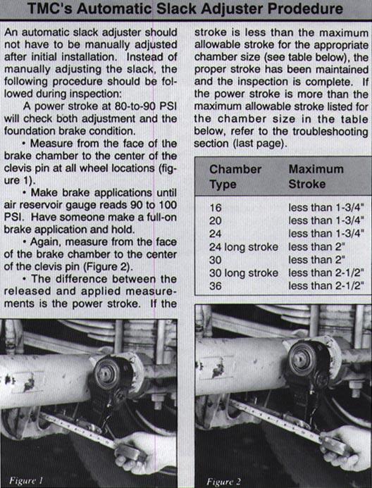
1 Pinpointing Braking Failures Is It the Slack Adjuster? Or Is It the Foundation Brake? A slack adjuster - regardless if it s manual or automatic - is a lever used to actuate brakes. As its name implies, it is also a device which takes up the slack or excess clearance caused by lining and drum wear. Although manual and/or automatic slack adjusters are required to apply the brakes, there are significant differences in operation and maintenance procedures. A manual slack adjuster is typically adjusted at every inspection by the driver, or by driver request. Several methods exist for manually adjusting brakes. One method is to rotate the adjusting hex nut until the brake linings contact the drum, then back the adjustment off one-half turn. Another method is to pull on the slack arm while adjusting the hex nut and setting. Two ways to check if the manual slack is in proper adjustment is to tap on the brake drum and listen for a ringing sound, or jack the vehicle up and rotate the tire to detect brake drag. Conversely, an automatic slack adjuster should never have to be manually adjusted except at installation of the ASA or when repairing the brakes. The method we prefer for checking brakes is the one suggested by the U.S. Department of Transportation which calls for stroke measurement to be taken at an 80-to-90 PSI brake application. Using this method, a power stroke measurement will alert you to the following operating characteristics of the braking system. Each of these items affects braking performance and pushrod stroke.
2 Al Factor: This is a measurement of leverage which is obtained by multiplying the area of the brake chamber by the effective length of the slack adjuster. Thus, the chamber size and slack adjuster arm length directly affect the amount of brake torque (force) which is generated. At an 85-PSI brake application, the difference in stroke between a 5-1/2 and a 6-1/2 slack adjuster can be as much as.40. Brake Stiffness: The amount of give and take in a brake assembly can vary greatly with the stiffness of the brake drum and foundation hardware. Shoe-to-Drum Clearance: An increase in shoe-to-drum clearance from the industry average of.025 to.050 can cause pushrod travel to increase by.625. Maintaining proper clearance is necessary in order for other components of the system to remain proportional and perform effectively. Burnish Quality: Unburnished linings which do not properly mate with the brake drum increase the lining to drum clearance and result in lower braking force. High and low spots on the brake friction material can hinder full contact of the lining to the brake drum and can also weaken brake performance. Because of this, the power stroke will be greater immediately after brake relining, and will decrease as the brake lining becomes burnished. Other Brake Hardware/Maintenance Deficiencies Associated With the Foundation Brake: The principal reason to take a brake stroke measurement is that it gives clues to the condition of the foundation brake and the lining-to-drum clearance. Severely worn, missing or broken brake components can cause you to fail roadside inspections even if lining-to-drum clearance is good. When inspecting brakes, don t overlook severely worn cam bushings, missing S-cam rollers, and cracked brake drums, since they can play as much havoc with your braking system as worn linings and drums. Replace the camshaft bushing at every brake reline. It is the most overlooked part of the foundation brake. It centers the cam and brake shoe assemblies in the brake drum. Always replace fittings, line sizes, and valves with the exact parts to prevent altering the brake balance. Changes in the line size and/or fittings will change air system performance. Longer lines or larger diameter lines will slow down delivery timing. Restricted fittings and 90-degree elbows slow air delivery to the brake chamber.
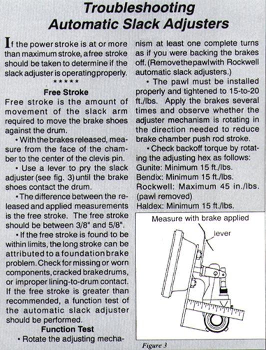
3 Always replace brake linings with the same friction characteristics as the OEM lining that came with the new vehicle and never mix different linings with different friction ratings on the same axle. Inspect brake shoe tables for rust pits, bent shoe tables and elongated rivet holes to ensure product quality. Brake shoes must be checked for wear at anchor pin holes and at roller pin seats to prevent noise and ensure brake performance. Each web must be checked for stretching and cracks. Lubricate the brakes on a scheduled basis, but don t over-lube and never put any kind of lubricant on the cam head or rollers. Too much grease in the bushings can drip onto the lining and drum causing a brake that cannot effectively stop. Although a free stoke measurement (the distance the slack adjuster travels from the release position until the shoes contact the drum) will not only tell you if the brakes are in adjustment, or have a dragging brake, it is a good method for mechanics to troubleshoot ASAs. When using this method you should have a free stroke between 3/8 to 5/8. If the pushrod stroke is greater than the maximum, legally-allowable stroke for the appropriate chamber size, then the automatic slack adjuster should be tested for operation. All automatic slack adjusters can be easily tested to detect if they are functioning properly. A simple check can be performed on the ASA by backing off the slack adjuster threequarters of a turn. Be sure to follow the manufacturer s procedure. Mark the adjusting mechanism and apply the brakes several times. The mark should rotate indicating the slack adjuster is adjusting. If rotation does not occur, the slack adjuster should be replaced. A function test of the automatic slack adjuster can also troubleshoot slack adjuster operation. Use a torque wrench to back off the slack adjuster as shown in the photo. Some manufacturers require a minimum torque value, others a maximum value. However, in either case, if torque values are not correct, the slack adjuster should be replaced. Consult the individual manufacturer for the correct torque values and procedures. Aside from checking for operation, the only other maintenance required on an automatic slack adjuster is to inspect the unit for structural damage, and lubricate the slack adjuster


4 according to the manufacturer s recommendation. You should also pay close attention to the attaching hardware, such as clevis pins and bushings. TMC has revised its Recommended Practice for slack adjusters (RP 609). The Recommended Practice will contain information on installation, inspection and maintenance of automatic slack adjuster. Government testing and fleet usage have proven automatic slack adjusters are beneficial from a maintenance and safety aspect. However, successful operation depends largely on your employees understanding the operation and maintenance required when using automatic slack adjusters.
5
6

7 Some brake chamber push rods are marked to warn of an over-stroke condition. While the markings themselves vary, the marking system has two basic points. As shown in the figure above, there is a mark on the portion of the push rod near its clevis attachment to signal that it incorporates a stroke alert indicator. There is a mark on the brake chamber push rod opposite its clevis attachment and which is exposed from the brake chamber whenever over-stroke occurs.
Module 6: Air Foundation Brakes
 Air Brakes Terms and Definitions Basic Components That Make Up Air Foundation Brakes Types of Air Foundation Brakes Parts of a Cam Foundation Brake Parts of a Wedge Foundation Brake Parts of a Disc Foundation
SuperTrac. Axle. Service & Maintenance. Manual
 SuperTrac Axle Service & Maintenance Manual Table of Contents Page Exploded Views Section 1: General Information General Warnings Description of Axle Models Identifications Section 2: Installation Axle
Premium wheel-end brake products
 Premium wheel-end brake products Spicer Automatic Slack Adjuster Service Manual Self Adjusting Brake Adjuster The description and specifications contained in this service publication are current at the
S-ABA Service Manual. Self-Setting Automatic Brake Adjusters
 S-ABA Service Manual Self-Setting Automatic Brake Adjusters Warning: Haldex strongly recommends routine visual checks be performed at EACH maintenance service interval. Foundation brake operational checks
Service Manual Truck and Trailer Applications. AA1 Automatic Brake Adjusters
 Service Manual Truck and Trailer Applications AA1 Automatic Brake Adjusters Table of Contents Operation... 1 Brake Adjuster Part Number and Build Date... 1 Steer Axle Applications... 2 Drive Axle Applications...
L Rev. 10/04. CSI Midland/Gunite Automatic Brake Adjuster Service Manual
 L30006 Rev. 10/04 CSI Midland/Gunite Automatic Brake Adjuster Service Manual TABLE OF CONTENTS Overview...3 Installation Procedures...4 Brake Adjustment...10 Installation Procedures...11 Brake Adjustment...13
Air Brake Inspection Presented By: G.L. May
 Air Brake Inspection 2012 Presented By: G.L. May Outline of this course Objective of this course: The technician will have a better understanding of requirements for air drum brakes and air disc brakes
NHVIM Section 2 BASIC BRAKES MAINTENANCE
 NHVIM Section 2 BASIC BRAKES MAINTENANCE Chair Lance Fisher, JLP Panel Members - Andrew Archibald, TMR Queensland - Renzo Barone, Meritor - Kevin Gibson, Knorr-Bremse Chair Lance Fisher, JLP Panel Members
Air Brake Adjustment. What You ll Learn After reading this chapter you will be able to:
 8 Air Brake Adjustment Fast Fact Your company may have a maintenance crew to keep vehicles safely running. But one person alone is ultimately responsible to ensure that the brakes are operating properly
Refer to separate Installation Instructions for installation details.
 OWNER S GUIDE 8A000729 DuraLift 13.5 13,500 CAPACITY Link Mfg. Ltd. 223 15th St. N.E. Sioux Center, IA USA 51250-2120 www.linkmfg.com QUESTIONS? CALL CUSTOMER SERVICE 1-800-222-6283 DEALER / INSTALLER:
Cam Brakes. Table of Contents
 Sub-Headings Introduction 3 Q Plus 3 Disassembly 4 Remove the Wheel Components 4 Automatic Slack Adjuster 4 Brake Shoes 5 Remove Camshaft and Auto Slack Adjuster 6 Preparing Parts for Assembly 6 Clean
MGM Brakes Service Manual
 MGM Brakes Service Manual MAGNUM Performance Plus Spring Brake Actuators (MJ-Series 3.00 / 76mm Long Stroke ) For: S-Cam Tamper-Resistant MAGNUM Performance Plus Spring Brake Actuators Figure 1 A B C Your
CHAPTER 14 PARKING BRAKE
 1 page INDEX1 PARKING BRAKE 14-1 14-143E-05 CHAPTER 14 PARKING BRAKE 1Models FA and FB with LF05S TROUBLESHOOTING...14-2 SPECIAL TOOLS...14-3 INSPECTION AND ADJUSTMENT...14-4 PARKING BRAKE...14-7 14 PARKING
FAST BRAKE INDEX. trouble-shooting guide
 FAST BRAKE trouble-shooting guide INDEX INTRODUCTION 3 PRECAUTIONS 3 INSPECTION 4 Q&A Why does my spring brake have square air-inlet ports? 4 Why is the yoke welded to the service push-rod? 6 What do I
MGM Brakes Service Manual
 MGM Brakes Service Manual For: S-Cam Piston Type Service and Spring Brake Chambers Form No. 5009 Issued 6/91 - Revised 4/2010 MODEL MB-T SERIES MODEL MG-T SERIES Superseded by the MJS SERIES Form #5044
OWNER S GUIDE 8A DURALIFT II 13,200 LB. CAPACITY. Link Mfg. Ltd th St. N.E. Sioux Center, IA USA
 OWNER S GUIDE 8A000715 DURALIFT II 13,200 LB. CAPACITY Link Mfg. Ltd. 223 15th St. N.E. Sioux Center, IA USA 51250-2120 www.linkmfg.com QUESTIONS? CALL CUSTOMER SERVICE 1-800-222-6283 DEALER / INSTALLER:
SERVICE BULLETIN No. 1088
 SERVICE BULLETIN No. 1088 Circulate to listed addressees COACH MODEL BULLETIN TYPE MANUAL & SECTION : T800 Series; T900 Series; T 2100 Series; C2045 : Service Information : Maintenance Manual: Chapter
SD Bendix ASA-5 Automatic Slack Adjuster DESCRIPTION OPERATION BRAKE APPLICATION GENERAL
 SD-05-1269 Bendix ASA-5 Automatic Slack Adjuster DESCRIPTION The Bendix ASA 5 automatic slack adjuster is designed for use on cam actuated drum brakes of the type in use on most highway vehicles. Like
Recommended Brake Assembly/Disassembly Procedure
 Recommended Brake Assembly/Disassembly Procedure Although Dexter Axle supplies non-asbestos brake linings as standard equipment, asbestos linings may still be found on axles in service.! CAUTION POTENTIAL
Product Catalogue. Version 8.0. Section. FUWA Axle Components
 Product Catalogue Section E Version 8.0 FUWA Section E Fuwa - Cam and Brake Assembly E:48 PRODUCT CATALOGUE 8.0 Fuwa - Cam and Brake Assembly Part List - 6 axle tube (square) - 5 axle tube (round) TL-11-427-800045
SERVICE INFORMATION Brake S-Camshafts
 SERVICE INFORMATION 12.25 Brake S-Camshafts New Style Cam (1½ Roller) Old Style Cam (1¼ Roller) Head Marking: 0794L & 0794R (as of July 1994) Head Marking: M12L & M12R The old style cam has been discontinued
Sisu S-Cam Drum Brakes
 Sisu S-Cam Drum Brakes (For hub reduction rear axles since 1992) Maintenance Manual Sisu Axles, Inc. Autotehtaantie 1 P.O. Box 189 FIN-13101 Hämeenlinna Finland Phone int + 358 204 55 2999 Fax int + 358
SD Bendix Manual Slack Adjusters DESCRIPTION ADJUSTING MECHANISM OPERATION
 SD-05-1200 Bendix Manual Slack Adjusters WORM SHAFT (LOCK SCREW) FIGURE 1 - POSITIVE LOCK TYPE SLACK ADJUSTER DESCRIPTION In an s-cam type foundation brake, the final link between the pneumatic system
CAUTION. Hydraulic Brakes. Braking Systems - Hydraulic
 Hydraulic Brakes The hydraulic brakes on your trailer are much like those on your automobile or light truck. The hydraulic fluid from a master cylinder or actuation system is used to actuate the wheel
Slack Adjuster. Table of Contents
 Slack Adjuster Table of Contents Sub-Headings Automatic Slack Adjuster Service 2 PayMaster Automatic Slack Adjuster 2 How the Automatic Slack Adjuster Works 2 Pressed-In, Sealed Actuator Boot 3 Handed
Surge Brake Troubleshooting Tips
 Surge Brake Troubleshooting Tips Surge Brake Troubleshooting Tips Think Safety!! Don t attempt working on your brakes if you aren t experienced with brake systems. These troubleshooting tips assume a person
Webinar Series. APTA Bus Technical Maintenance Committee Webinar Series. Disc Brake Wheels On Inspection. Presents
 1 Webinar Series APTA Bus Technical Maintenance Committee Webinar Series Presents Disc Brake Wheels On Inspection January 28, 2015 2 Introduction Welcome to today s webinar in which we will cover a wheels
MERITOR ALLFIT CLEARANCE-SENSING AUTOMATIC SLACK ADJUSTERS COMPLETE PORTFOLIO TO MEET EVERY APPLICATION AND BUDGET.
 MERITOR ALLFIT CLEARANCE-SENSING AUTOMATIC SLACK ADJUSTERS COMPLETE PORTFOLIO TO MEET EVERY APPLICATION AND BUDGET. SMART ASA CHOICES FROM MERITOR. YOUR TRUSTED SOLUTIONS PROVIDER. As a leading supplier
CAUTION. Hydraulic Brakes. Braking Systems - Hydraulic
 Hydraulic Brakes Dexter offers several varieties of hydraulic trailer brakes. Your vehicle may be equipped with drum brakes or disc brakes. The hydraulic brakes on your trailer are much like those on your
Product Customization Guide TSE Brakes, Inc.
 Revision Date: June 7, 2018 Revision: 4 Page: 1 of 13 CONTENTS Brake Chamber Clamp Repositioning Instructions 2-3 Mechanical Release of Spring Brakes (Caging) 4-6 Installation Instructions 7-9 Determine
Webinar Series APTA Standards Quarterly Webinar Series
 1 Webinar Series APTA Standards Quarterly Webinar Series Presented by APTA Brake and Chassis Working Group Disc Brake Wheels On Inspection January 26, 2017 2 Moderator Presenter Jerry Guaracino Assistant
TRAILER AXLE MAINTENANCE
 Purpose To maintain and extend the product life of the Trailer Axle product line. Safety Failure to follow the instructions provided in this manual may result in death, serious personal injury, severe
TMC TRAILER AXLE SERVICE MANUAL DRUM BRAKE AXLES
 8 8 TMC Australia a Pty Ltd TMC TRAILER AXLE SERVICE MANUAL DRUM BRAKE AXLES TMC 0 59 TMC TRAILER AXLE TMC TRAILER AXLE TMC TRAILER AXLE TM 0 5 9 TMC Australia Pty Ltd Telephone: + 6 3 8786 3688 78 Star
 DRUM BRAKE RIMS Periodic inspection of drum brake rims is necessary to determine indications of uneven or excessive wear. In general, brake rim failures other that regular wear are caused by brake linings
INSTALLATION INSTRUCTIONS
 INSTALLATION INSTRUCTIONS BIG ROTOR / CALIPER RELOCATION REAR KIT SUM-BK1423 1999-2009 GM 1/2 Ton Trucks & SUVs Thank you for choosing SUMMIT RACING for your braking needs. Pleases take the time to read
TRUCKINGTRUTH.COM T T. Daniel B s Pre-Trip Inspection Checklist
 TRUCKINGTRUTH.COM T T Daniel B s Pre-Trip Inspection Checklist 1 My pre-trip begins as I approach the vehicle. I am looking for leaks, leaning one way or the other (which may indicate a low tire or bad
BRAKE INFORMATION FOR FKH AXLES
 BRAKE INFORMATION FOR FKH AXLES S-CAM ROTATION ON DRUM BRAKE AXLES It is our recommendation (it is also a general industry recommendation) to install Drum Brake Axles so that the S-Cams rotate in the same
Inspection and Basic Maintenance of Brake Systems
 Inspection and Basic Maintenance of Brake Systems 11-1 Types Air brakes Hydraulic brakes Secondary braking systems 11-2 Air Brake System Most large, modern fire apparatus are equipped with air-operated
Service Manual Blue Giant
 R 2000 Service Manual Blue Giant Models PT-50 and PT-55 Developed by Super Stores Service This manual is intended for basic service and maintenance of the Blue Giant pallet jack. The pallet jacks you are
BRAKE SYSTEM Return To Main Table of Contents
 BRAKE SYSTEM Return To Main Table of Contents GENERAL... 2 BRAKE PEDAL... 10 MASTER CYLINDER... 13 BRAKE BOOSTER... 16 BRAKE LINE... 18 PROPORTIONING VALVE... 19 FRONT DISC BRAKE... 20 REAR DRUM BRAKE...
Axle Components. 12,000 lbs. Capacity
 12,000 lbs. Heavy Duty Components 27-358 Unitized Oil Seal - disc or drum (Dimensions are 3.125 x 4.506 x.605) 2 010-056-00 27-342 3984 Inner Bearing (Inside diameter 2.625 ) 3 031-020-02 27-343 3920 Inner
1994 Mazda MX-5 Miata. BRAKE SYSTEM 1994 BRAKES Mazda - Disc & Drum BRAKES Mazda - Disc & Drum
 BRAKE PEDAL FREE PLAY 1994 Mazda MX-5 Miata DESCRIPTION & OPERATION BRAKE SYSTEM 1994 BRAKES Mazda - Disc & Drum NOTE: For information on anti-lock brake systems, see ANTI-LOCK BRAKE SYSTEM article in
NATEF Task List - Medium/Heavy Duty Truck Brakes
 The first task in is to listen to and verify the operator s concern, review past maintenance and repair documents, and determine necessary III. BRAKES A. Air 1 2 3 4 5 6 7 8 9 10 11 12 1. Air Supply and
SECTION 4A HYDRAULIC BRAKES
 SECTION 4A HYDRAULIC BRAKES Caution: Disconnect the negative battery cable before removing or installing any electrical unit or when a tool or equipment could easily come in contact with exposed electrical
DODGE 3 SUSPENSION LIFT KIT
 921351200 Kit Contents: 9280:Front Coil Springs 1351BOX1: Upper Control Arms Lower Control Arms Sway bar Brackets Brake Proportioning Valve Bracket Track Bar Relocation Bracket 1351BOX2: 5.75 Blocks U-bolt
Bullseye October Product In Focus - Camshafts. Features. Basic Diagram of a Camshaft. Meritor's Top Movers - Camshafts
 In this Issue: Product In Focus Global News New Products Supersessions Getting Technical Staff Profile Advertising Product In Focus - Camshafts Features A premium quality range of Camshafts produced exclusively
Hydraulic Wheel Dolly
 Hydraulic Wheel Dolly Operating Instructions & Parts Manual Model Number HW93766 Capacity 3/4 Ton Made in the U.S.A. This is the safety alert symbol. It is used to alert you to potential personal injury
Cam Brakes and Automatic Slack Adjusters
 Maintenance Manual 4 Cam Brakes and Automatic Slack Adjusters Revised 08-16 Service Notes About This Manual This manual provides maintenance and service information for Meritor cam brakes and automatic
Part II NORTH AMERICAN STANDARD VEHICLE OUT-OF-SERVICE CRITERIA POLICY STATEMENT
 Part II NORTH AMERICAN STANDARD VEHICLE OUT-OF-SERVICE CRITERIA POLICY STATEMENT The purpose of this part is to identify Critical Vehicle Inspection Items and provide criteria for declaring vehicles out-of-service
Click Here for Printable PDF File. CHAPTER 3 - BASIC INFORMATION for PERFORMING HYDRAULIC SYSTEM MAINTENANCE
 HWH Online Technical School Lesson 1: Introduction to Hydraulics Chapter 3 - "BASIC INFORMATION for PERFORMING HYDRAULIC SYSTEM MAINTENANCE" (Filename: ML57000-012-CH3.DOC Revised: 22APR16) Click Here
DIAMOND ROLLER CHAIN. For Agricultural and Construction Equipment
 DIAMOND ROLLER CHAIN For Agricultural and Construction Equipment FABRICATION While roller chain would appear to be a simple product, the number of components in a ten foot section of 40 pitch chain totals
Seabee Annual/100-Hour Inspection
 Date Completed Seabee Annual/100-Hour Inspection ENGINE Mechanic s Initials 1 Drain engine oil and check for foreign material 2 Check oil screen for proper rotation or looseness 3 Safety Oil Plug 4 Refill
INSTALLATION INSTRUCTIONS
 INSTALLATION INSTRUCTIONS REAR DRUM TO DISC BRAKE CONVERSION KIT A130 JEEP CJ SERIES W/AMC-20 REAR AXLES AND 5 x 5-1/2" BOLT CIRCLE Thank you for choosing STAINLESS STEEL BRAKES CORPORATION for your braking
FMCSA Brake Regulations 101
 FMCSA Brake Regulations 101 Build your foundation on the knowledge of the brake regulations 393.40 393.55 396.19 & 396.25 Appendix G 2/27/17 Required FMCSA Brake Regulations to Teach, Train, and Test 1
1. IMPORTANT NOTICES subject to change without notice. NOTE
 1. IMPORTANT NOTICES This manual is provided to every owner of a new Deloupe trailer. The manual outlines the appropriate maintenance and operation procedure so that you as an owner/operator will get the
Your Brakes. Fundamentals of Braking
 B U S S E R V I C E, I N C. Your Brakes Fundamentals of Braking There are a variety of mechanical forces and physical components that make up the braking system of your coach. The forces that effect your
Electric Brakes. Braking Systems - Electric
 Electric Brakes The electric brakes on your trailer are similar to the drum brakes on your automobile. The basic difference is that your automotive brakes are actuated by hydraulic pressure while your
MGM Brakes Service Manual
 MGM Brakes Service Manual MODEL LTR-T - 2.50 Pre 6/1/98 MODEL LTR-T - 2.50 Post 5/31/98 MODEL LTR-L3-3.00 For: Long Life Integral Release Bolt Double Diaphragm Spring Brakes Several design improvements
Seatbelt Solutions
 Seatbelt Solutions www.seatbeltsolutions.com 3-Point Conversion Seatbelt Installation Guide for: 1947-1967 Trucks Seatbelt Solutions 90 Degree Bracket 7/16 Stud Plate 1 1/2 x 7/16 x20 Bolts Pop Rivets
INSTALLATION INSTRUCTIONS
 INSTALLATION INSTRUCTIONS INSTRUCTION FOR ASSEMBLY OF JEEP CJ SERIES W/AMC 20 REAR AXLES, 5 x 5-1/2" BOLT CIRCLE WITH A130-1 FULL FLOATING AXLE OR A130-2 (1 PIECE AXLE) Thank you for choosing STAINLESS
Service Manual for Drum Brake Axles Tapered and Parallel Spindle Axles
 Service Manual for Drum Brake Axles Tapered and Parallel Spindle Axles XL-TA10006OM-en-US Rev C Contents Contents Page Introduction... 3 Warranty... 3 Notes, Cautions, and Warnings... 3 Section 1 General
Heavy-Duty P Series Cam Brakes
 Maintenance Manual MM-0440 Heavy-Duty P Series Cam Brakes Issued 09-04 Service Notes About This Manual This manual provides maintenance and service information for Meritor heavy-duty P Series cam brakes.
Mopar 8 3/4 & 9 3/4 (Dana) Installation Instructions Rear Disc Conversion
 Installation Instructions Rear Disc Conversion") Mopar 8 3/4 & 9 3/4 (Dana) Installation Instructions Rear Disc Conversion This kit is for either Mopar 8 ¾ or Mopar 9 ¾ (Dana). This kit is designed to work with axles with either GM 5 x 4.75 Bolt Pattern
Mopar 8 3/4 & 9 3/4 (Dana) Installation Instructions Rear Disc Conversion This kit is for either Mopar 8 ¾ or Mopar 9 ¾ (Dana). This kit is designed to work with axles with either GM 5 x 4.75 Bolt Pattern
Hudson-Essex. Service Manual Supplement. Hudson Cars 750,001 up
 1 9 2 6 Hudson-Essex Service Manual 1927 Supplement Hudson Cars 750,001 up Hudson Rear Axle (Cars numbered 750,001 and upward) Brakes (Cars numbered 750,001 and upward) See page 18 Transmission Group
Advanced Auto Tech. ASE A 1 Test Preparation Engine Upper End Theory & Service
 Advanced Auto Tech ASE A 1 Test Preparation Engine Upper End Theory & Service Torque to yield bolts stretch to their yield point when tightened and should not be reused. True or False The sealing lip &
PROPELLER SHAFTS 16-1 PROPELLER SHAFTS CONTENTS
 Z PROPELLER SHAFTS 16-1 PROPELLER SHAFTS CONTENTS page GENERAL INFORMATION... 1 PROPELLER SHAFT REPLACEMENT... 7 SERVICE DIAGNOSIS/PROCEDURES... 3 page TORQUE SPECIFICATIONS... 14 UNIVERSAL JOINT REPLACEMENT...
4. MAINTENANCE MANUAL
 4. MAINTENANCE MANUAL 4.1 INTRODUCTION The maintenance program has been developed by ORIENTAL in accordance to our supplier s own maintenance program for each component. Conforming to this maintenance
Heavy Duty Jack Stands
 Heavy Duty Jack Stands Operating Instructions & Parts Manual Made in the U.S.A. Model Number HW93511 Capacity per pair 10 Ton Model Number HW93512 Capacity per pair 10 Ton This is the safety alert symbol.
GM Full-Size Trucks Repair Information
 . 1 of 12 12/26/2009 10:47 AM GM Full-Size Trucks 1988-1998 Repair Information Brake Shoes INSPECTION REMOVAL & INSTALLATION ADJUSTMENT INSPECTION 1. 2. 3. 4. 5. Raise and support the rear end on jackstands.
& OPERATING INSTRUCTIONS
 ELECTRIC WINCH 12 / 24 VOLT DC DW5000 (5000LBs/2272Kg) DW6000 (6500LBs/2727Kg) DW8000 (8000LBs/3663Kg) DW8500 (8500LBs/3863Kg) DW9000 (9000LBs/4091Kg) ASSEMBLY & OPERATING INSTRUCTIONS DW5000 Specification
CENTAC Inlet and Bypass Valve Positioners
 CENTAC Inlet and Bypass Valve Positioners INGERSOLL-RAND AIR COMPRESSORS INLET AND BYPASS VALVE POSITIONERS Copyright Notice Copyright 1992, 1999 Ingersoll-Rand Company THIS CONTENTS OF THIS MANUAL ARE
Recommended Practice
 Recommended Practice Proposed RP 261 (T) VMRS 004-013-001 CONSIDERATIONS FOR AERODYNAMIC WHEEL COVERS PREFACE The following Recommended Practice is subject to the Disclaimer at the front of TMC s Recommended
5,500 lbs. Pallet Jack
 5,500 lbs. Pallet Jack ATD-7406 Operating Instructions & Parts Manual Capacity 5,500 lbs.! The safety alert symbol is used to alert you to potential personal injury hazards. Obey all safety messages that
SECTION 4A BRAKE SYSTEM TABLE OF CONTENTS
 SECTION 4A BRAKE SYSTEM TABLE OF CONTENTS Description and Operation... 4A-2 Braking System Testing... 4A-2 Hydraulic Brake System... 4A-2 Brake Pedal... 4A-2 Master Cylinder... 4A-2 Brake Booster... 4A-3
As stated, these are solely based off of how I like to do the Pre-Trip. I give my personal opinions as well as some helpful tips.
 Here are our sections: Engine Compartment Drivers Door Fuel Area Coupling System Trailer (Please note in the type of suspension your trailer has) Light Check In-Cab Inspection and Brake Tests You will
WD DODGE SUSPENSION LIFT KIT P/N
 4/03/03 94-01 4WD DODGE 1500 3 SUSPENSION LIFT KIT P/N 10-46094 NOTE: Each lift kit, and options to lift kits, are packaged separately. Therefore installation procedures are covered in separate instructions.
Hands On Test Scoring Instructions
 Hands On Test Scoring Instructions Each scoring box contains 3 to 6 line items and up to 7 numbers plus a 0. Each section has a separate criteria for scoring. Based on the criteria, you will score the
For Use With Power Units Mounted on M200A1 Trailers Only
 TASK COMPLETION WORKSHEET WORK ORDER# SERIAL # Form : Each task shall be completed by an individual working in the section listed for the task. This individual shall write their employee number in the
55-64 Full Size GM (Impala, Bel Air, etc.) This kit is for axles with a 3 3/8 spread center to center on the top two bolt holes (pictured left).
 This kit is for axles with a 3 3/8 spread center to center on the top two bolt holes (pictured left).") SUM-BK1624A Full Size GM Installation Instructions Rear Disc Conversion 55-64 Full Size GM (Impala, Bel Air, etc.) This kit is for axles with a 3 3/8 spread center to center on the top two bolt holes (pictured
SUM-BK1624A Full Size GM Installation Instructions Rear Disc Conversion 55-64 Full Size GM (Impala, Bel Air, etc.) This kit is for axles with a 3 3/8 spread center to center on the top two bolt holes (pictured
Preventive Maintenance Inspection Form: Trailers
 Preventive Maintenance Inspection Form: Trailers A. Under Structure Test glad hands (glad hand with gauge and valve) Air hose Review history record and insure that parts necessary to complete inspection
INSTALLATION INSTRUCTIONS
 INSTALLATION INSTRUCTIONS BIG ROTOR / CALIPER RELOCATION FRONT KITS SUM-BK1422, BK1423, BK1424 1999-2006 GM 1/2 Ton Trucks & SUVs Thank you for choosing SUMMIT RACING for your braking needs. Pleases take
PNEUMATIC SLIDING VALVE
 INSTALLATION, OPERATION, & #: MM-SV001 6-23-09 Rev. A Page 1 of 8 PNEUMATIC SLIDING VALVE PART NUMBERS (Including, but not inclusive) SV704MSTS, SV714MSTS, SV754MSTS, SV764MSTS, SV774MSTS, SV706MSTS, SV716MSTS,
A /F/X Body Instruction Packet Rear Disc Conversion
 A /F/X Body Instruction Packet Rear Disc Conversion 64-72 A Body / 67-81 F Body / 62-74 X Body This kit is for axles with a 3 1/8 spread center to center on the top two bolt holes (pictured left). Rotor
INSTRUCTION MANUAL ALL TERRAIN PALLET TRUCK HAND PALLET TRUCK
 INSTRUCTION MANUAL ALL TERRAIN PALLET TRUCK HAND PALLET TRUCK WARNING! 1. Read and understand instruction manual before using the pallet truck. 2. Do not place hands or feet under the pallet truck at any
INSTALLATION INSTRUCTIONS
 INSTALLATION INSTRUCTIONS Disc Brake Spindle Kit SUM-BKA2447 1964-72 A-BODY 1967-69 F-BODY 1968-74 X-BODY Thank you for choosing SUMMIT RACING for your braking needs. Please take the time to read and carefully
TMC Axle Installation and Service Manual
 Axle Installation TMC Axle Installation and Service Manual The Group Disclaimer Versioning The author and publisher have made their best efforts to prepare this manual, and the information contained in
Installation Instructions
 Preparing your vehicle to install your brake system upgrade 1. Rack the vehicle. 2. If you don t have a rack, then you must take extra safety precautions. 3. Choose a firmly packed and level ground to
INTRODUCTION. Safety Warnings
 INTRODUCTION The purpose of this manual is to familiarize yourself with an IMT axle. Topics included will cover: Installation Adjustments Maintenance Inspections This manual also contains information in
Kysor On/Off Rear Air Fan Drive
 . Proper precautions must be taken to prevent personal injury from contact with moving parts, unintended engine start, or other hazards present when working with powered equipment. Refer to the vehicle
Off-Highway Axle Planetary Wheel Ends
 Maintenance Manual MM-1189 Off-Highway Axle Planetary Wheel Ends Revised 06-16 Service Notes About This Manual This manual provides service and repair procedures for planetary wheel ends on off-highway
CHASSIS CONTENTS EXTERIOR PARTS 6-1 FRAME COVER 6-2 REAR FRAME COVER 6-4 FRONT WHEEL 6-6 FRONT BRAKE 6-10 HANDLEBARS 6-17 FRONT FORK 6-19
 CHASSIS CONTENTS EXTERIOR PARTS 6- FRAME COVER 6- REAR FRAME COVER 6-4 FRONT WHEEL 6-6 FRONT BRAKE 6-0 HANDLEBARS 6-7 FRONT FORK 6-9 STEERING 6-6 REAR WHEEL 6-3 REAR BRAKE 6-39 6 REAR SHOCK ABSORBER 6-43
SECTION 4A HYDRAULIC BRAKES
 SECTION 4A HYDRAULIC BRAKES CAUTION: Disconnect the negative battery cable before removing or installing any electrical unit or when a tool or equipment could easily come in contact with exposed electrical
PRE-TRIP INSPECTION CDL SKILLS TEST
 CDL SKILLS TEST PRE-TRIP INSPECTION Engine Compartment +1 Axle Side and Back of Truck +1 Axle Connections and Trailer +1 Axle External Light Check In-Cab with Brake Check 1810 N WATKINS RD, WATKINS, CO
SAFETY. Hitchpole, centre frame 1. Centre frame wheels & roller 3. Centre & wing frames 5. Wing frame wheels & roller 9.
 MANUAL Hitchpole, centre frame 1 Centre frame wheels & roller 3 Centre & wing frames Wing frame wheels & roller 9 Hydraulics 11 Clearance lights 13 Operations 1 Safety, warranty 1 SAFETY Industrial Drive,
INSTALLATION INSTRUCTIONS
 INSTALLATION INSTRUCTIONS R1 REAR DRUM TO DISC BRAKE CONVERSION KIT A130-3 JEEP CJ SERIES W/AMC-20 REAR AXLES AND 5 x 5-1/2" BOLT CIRCLE Thank you for choosing STAINLESS STEEL BRAKES CORPORATION for your
INSTALLATION INSTRUCTIONS
 INSTALLATION INSTRUCTIONS INSTALLATION INSTRUCTIONS FOR A136 REAR DRUM TO DISC BRAKE CONVERSION KIT for 1970-75 Jeep, CJ SERIES with Dana 44 flanged axle Thank you for choosing STAINLESS STEEL BRAKES CORPORATION
Maintenance and Parts Manual ADZ Series Suspension
 Maintenance and Parts Manual ADZ Series Suspension XL-PS10452MM-en-US Rev C Contents Contents Page Introduction... 3 Warranty... 3 Notes, Cautions, and Warnings... 3 Section 1 General Safety Instructions...
Kysor Rear Air Fan Drives
 On/Off Technology for Heavy-Duty Truck Applications Installation & Service Guide Kysor Rear Air Fan Drives thermal.borgwarner.com For Additional BorgWarner Thermal Systems Information: 800-927-7811 USA
BRAKES. Section III REAR AXLE DATA AND SPECIFICATIONS HAND BRAKE CHRYSLER SERVICE MANUAL BRAKES 17
 BRAKES 17 There is no basic design change in the rear axle and sure grip differential except the larger diameter pinion shaft is now used on all models for 1959. The Service Procedures will remain the
4.5 LIFT BOX KIT DODGE RAM 2500 & WD 7.3 DIESEL ONLY
 4.5 LIFT BOX KIT 2009 2010 DODGE RAM 2500 & 3500 4WD 7.3 DIESEL ONLY Fabtech Motorsports 4331 Eucalyptus Ave. Chino, CA 91710 Tech Line 909-597-7800 Fax 909-597-7185 Web www.fabtechmotorsports.com 4.5