LINESHAFT CONVEYOR STRAIGHT, CURVE AND SPUR TECH HANDBOOK TABLE OF CONTENTS
|
|
|
- Alaina Fisher
- 6 years ago
- Views:
Transcription


1
2 TABLE OF CONTENTS TABLE OF CONTENTS... 2 GENERAL SAFETY STATEMENTS Introduction Cautions, Warnings and Hazards... 3 SAFETY INFORMATION Safety Labels... 4, 5 -Installation Safety Electrical Safety Operational Safety Maintenance and Service Safety... 9, 10 -About Lineshaft Conveyors Lineshaft Safety Instructions RECEIVING AND INSPECTION Returns, Damages and Shortages Removal of Crating GENERAL INSTALLATION Overview Checking Unit Squareness Coupling / Attaching Bed Sections LEG SUPPORTS AND INSTALLATION Permanent Installation of Legs Leg Adjustments KNEE BRACES, CASTERS AND CEILING HANGERS Installing Knee Braces and Casters Installing Ceiling Hangers MULTI-TIER SUPPORTS Installation of Multi-Tier Supports PRE-START-UP OVERVIEW Preparing for Initial Start-Up Drive Chain and Sprocket Alignment Drive Chain and Sprocket Tension Gear Reducer Vent Plug MAINTENANCE Inspection and Lubrication Maintenance Schedules Report on Miscellaneous Maintenance Performed TROUBLESHOOTING AND REPLACEMENT PARTS Troubleshooting... 28, 29 PARTS LISTS Lineshaft Straight Lineshaft Curve Lineshaft Curve - Tangent Lineshaft Spur... 33, 34 NOTES WARRANTY

3 GENERAL SAFETY STATEMENTS IMPORTANT REQUIRED READING! IMPORTANTE! LECTURA OBLIGATORIA! To ensure this quality product is safely and correctly utilized, all instructions within this manual must be read and understood prior to equipment start-up. Be aware of all safety labels on machinery. If you do not understand any of the safety instructions or feel there may be safety labels missing, contact your supervisor or product supplier immediately! Para garantizar que este producto de calidad se utilice correctamente y con seguridad, es necesario leer y comprender las instrucciones incluidas en este manual, antes de comenzar a utilizar el equipo. Esté atento a todas las etiquetas de seguridad que se encuentran en las máquinas. Si no entiende alguna de las instrucciones de seguridad o considera que faltan algunas etiquetas de seguridad, comuníquese inmediatamente con su supervisor o proveedor del producto! COMPLIANCE WITH SAFETY STANDARDS Compliance with safety standards, including federal, state and local codes or regulations is the responsibility of the conveyor purchaser(s). Placement of guards, safety labels and other safety equipment is dependent upon the area and use to which the system is applied. A safety study should be made of the conveyor application by the purchaser(s). It is the purchaser s responsibility to provide any additional guards, safety labels or other safety equipment deemed necessary based on this safety study. The information contained in this safety manual is correct at the time of printing. Due to the continuing development of product lines, changes in specifications are inevitable. The company reserves the right to implement such changes without prior notice. If you suspect fire hazards, safety hazards, dangers towards health or any other job safety concerns, consult your federal, state or local codes. Certain safety information in this document was reprinted from ASME B by permission of The American Society of Mechanical Engineers. All rights reserved. Inspect equipment for safety labels. Make sure personnel are aware of and follow safety instructions. Maintain an orderly environment in the vicinity of the conveyor at all times. Clean up spilled materials or lubricants immediately. All personnel shall be instructed regarding the necessity for continuous care and attention to safety during the operation of a conveyor. They must be trained to identify and immediately report all unsafe conditions or practices relating to the conveyor and its operation. Know your company s machine specific Lockout / Tagout procedure. Do Not perform maintenance until electrical disconnect has been turned off! Replace all safety devices, guards and guarding prior to equipment start-up. References used for safety instructions in this manual are from: Conveyor Equipment Manufacturers Association (CEMA) and The American Society of Mechanical Engineers (ASME) 3


 Placed on terminating ends (both ends) where there are exposed moving parts which must be unguarded to facilitate function, i.e. rollers, pulleys, shafts, chains, etc.")
4 SAFETY INFORMATION: SAFETY LABELS Safety labels have been placed at various points on the equipment to alert everyone of potential dangers. Inspect equipment for proper position of safety labels and make sure all personnel are aware of the labels and obey their warnings. As mentioned in the previous section, a safety study should be made of the conveyor application by the purchaser(s). It is the purchaser s responsibility to provide any additional guards, safety labels or other safety equipment deemed necessary based on this safety study. The following pages contain typical safety labels that may have been attached to your equipment. # ( 5 x 2 1/2 ) Placed on terminating ends (both ends) where there are exposed moving parts which must be unguarded to facilitate function, i.e. rollers, pulleys, shafts, chains, etc. # (5 X 2 1/2 ) Placed next to drive (both sides) to warn personnel that the lineshaft conveyor utilizes a rotating shaft which may be hazardous if hair or loose clothing become entangled around the rotating shaft. Also used on any other conveyors where the exposed shaft may create similar hazards. # (5 X 2 1/2 ) General warning to personnel that the equipment s moving parts, which operate unguarded by necessity or function, i.e., air cylinders, etc., create hazards to be avoided. # ( 5 X 2 1/2 ) Placed on all chain guards to warn that operation of the machinery with guards removed would expose chains, belts, gears, shafts, pulleys, couplings, etc. which create hazards. # ( 5 X 2 1/2 ) Placed on max. of 20 centers (both sides) along conveyors which provide surfaces and profiles attractive, but hazardous, for climbing, sitting, walking or riding. # ( 5 X 2 1/2 ) Placed on chain guard base so label is visible when guard cover is removed. # ( 5 X 2 1/2 ) Placed next to drive (both sides) to warn maintenance personnel that conveyors must be shut off and locked out prior to servicing. Examples: drives, take-ups, and lubrication points, which require guard removal. 4 # ( 5 X 3 ) General warning of pinch point hazards. (Continued on next page)

 Placed on shipping brace which stabilizes equipment")

5 SAFETY INFORMATION: SAFETY LABELS (Continued) # ( 1 3/4 x 1 1/4 ) Generally placed on smaller guards to alert personnel of potential danger if guard is removed and power is not locked out. # ( 3 x 1 1/4 ) Placed on shipping brace which stabilizes equipment during shipping. Brace must be removed before operating! May cause severe injury if not removed. # (10 x 7 ) Placed on equipment where conveyors may start without warning. 5
6 SAFETY INFORMATION: INSTALLATION SAFETY 1) LOADING / UNLOADING Have trained personnel load or unload equipment. The conveyor must be properly handled when transferring from the unloading area to final site location to prevent damage. 2) GUARDS / GUARDING Interfacing of Equipment. When two or more pieces of equipment are interfaced, special attention shall be given to the interfaced area to ensure the presence of adequate guarding and safety devices. Guarding Exceptions. Wherever conditions prevail that would require guarding under this standard but such guarding would render the conveyor unusable, seek guidance from your safety professional. 3) ANCHORING DO NOT operate conveyor unless it is properly anchored. Serious injury or death may result. 4) SAFETY WARNING Install all safety devices, guards and guarding prior to equipment start-up. 6
7 SAFETY INFORMATION: ELECTRICAL SAFETY 1) ELECTRICAL CODE All electrical installations and wiring shall conform to federal, state and local codes. When conveyor operation is not required for a maintenance procedure, electrical power must be turned off and locked / tagged out following your company s machine specific procedure. 2) CONTROL STATION Control stations should be so arranged and located that the operation of the affected equipment is visible from them. Control stations shall be clearly marked or labeled to indicate the function controlled. A conveyor that would cause injury when started shall not be started until personnel in the area are alerted by a signal or by a designated person that the conveyor is about to start. Where system function would be seriously hindered or adversely affected by the required time delay, or where the intent of the warning may be misinterpreted (i.e., a work area with many different conveyors and allied devices), a clear, concise and legible warning sign needs to be provided. The warning sign shall indicate that conveyors and allied equipment may be started at any time, that danger exists and that personnel must keep clear. These warning signs shall be provided along the conveyor at areas not guarded by position or location. Remotely and automatically controlled conveyors, and conveyors where operator stations are not manned or are beyond voice or visual contact from drive areas, loading areas, transfer points and other potentially hazardous locations on the conveyor path not guarded by location, position or guards shall be furnished with emergency stop buttons, pull cords, limit switches or similar emergency stop devices. All such emergency stop devices shall be easily identifiable in the immediate vicinity of such locations unless guarded by location, position or guards. Where the design, function and operation of such conveyor clearly is not hazardous to personnel, an emergency stop device is not required. The emergency stop device shall act directly on the control of the conveyor concerned and shall not depend on the stopping of any other equipment. The emergency stop devices shall be installed so that they cannot be overridden from other locations. Inactive and unused actuators, controllers and wiring should be removed from control stations and panel board, together with obsolete diagrams, indicators, control labels and other material that might confuse the operator. 3) SAFETY DEVICES All safety devices, including wiring of electrical safety devices, shall be arranged to operate such that a power failure or failure of the device itself will not result in a hazardous condition. 4) EMERGENCY STOPS AND RESTARTS Conveyor controls shall be so arranged that, in case of emergency stop, manual reset or start at the location where the emergency stop was initiated shall be required for the conveyor(s) and associated equipment to resume operation. Before restarting a conveyor that has been stopped because of an emergency, an inspection of the conveyor shall be made and the cause of the stoppage determined. The starting device and electrical power must be turned off and locked / tagged out according to your company s machine specific procedure before any attempt is made to remove the cause of the stoppage, unless operation is necessary to determine the cause or to safely remove the stoppage. 5) SAFETY WARNING Replace all safety devices, guards and guarding prior to equipment start-up. 7
8 SAFETY INFORMATION: OPERATIONAL SAFETY Only trained, qualified personnel shall be permitted to operate a conveyor. Training shall include instruction in operation under normal conditions and emergency situations. Where safety is dependent upon stopping / starting devices, they shall be kept free of obstructions to permit access. The area around loading and unloading points shall be kept clear of obstructions that could endanger personnel. Do not ride the load-carrying element of a conveyor under any circumstances, unless the conveyor is designed and equipped with safety and control devices intended to carry personnel. For no reason shall a person ride any element of a vertical conveyor. Warning labels reading DO NOT RIDE CONVEYOR shall be affixed by the owner of the conveyor. Personnel working on or near a conveyor shall be instructed as to the location and operation of pertinent stopping devices. A conveyor shall be used to transport only a load that it is designed to handle safely. Under no circumstances shall the safety characteristics of the conveyor be altered. Routine inspections and preventative and corrective maintenance programs shall be conducted to ensure that all safety features and guards are retained and function properly. Inspect equipment for safety labels. Make sure personnel are aware of and follow safety label instructions. Alert all personnel to the potential hazard of entanglement in conveyors caused by items such as long hair, loose clothing and jewelry. SAFETY WARNING Replace all safety devices, guards and guarding prior to equipment start-up. 8
9 SAFETY INFORMATION: MAINTENANCE / SERVICE SAFETY ELECTRICAL POWER MUST BE TURNED OFF AND LOCKED / TAGGED OU T following your company s machine specific procedures when servicing conveyor to prevent accidental restarting by other persons or interconnecting equipment (when used). 1) MAINTENANCE (REPAIR) Maintenance and service shall be performed by trained, qualified personnel only. Where lack of maintenance and service would cause a hazardous condition, the user shall establish a maintenance program to ensure that conveyor components are maintained in a condition that does not constitute a hazard to personnel. No maintenance or service shall be performed when a conveyor is in operation. See Lubrication and Adjustment or Maintenance During Operation for exceptions. When a conveyor is stopped for maintenance or service, the starting devices, prime mover, powered accessories or electrical must be locked / tagged out in accordance with a formalized procedure designed to protect all persons or groups involved with the conveyor against an unexpected restart. Personnel should be alerted to the hazard of stored energy, which may exist after the power source is locked out. All safety devices and guards shall be replaced before starting equipment for normal operation. 2) ADJUSTMENT OR MAINTENANCE DURING OPERATION When adjustments or maintenance must be done while equipment is in operation, only trained, qualified personnel who are aware of the hazards of the conveyor in motion shall be allowed to make adjustments, perform maintenance or service. Conveyors shall NOT be maintained or serviced while in operation unless proper maintenance or service requires the conveyor to be in motion. If conveyor operation is required, personnel shall be made aware of the hazards and how the task may be safely accomplished. 3) LUBRICATION Conveyors shall NOT be lubricated while in operation unless it is impractical to shut them down for lubrication. Only trained and qualified personnel who are aware of the hazards of the conveyor in motion shall be allowed to lubricate a conveyor that is operating. Where the drip of lubricants or process liquids on the floor constitutes a hazard, drip pans or other means of eliminating the hazard must be provided by purchaser(s). 4) MAINTENANCE OF GUARDS AND SAFETY DEVICES Guards and safety devices shall be maintained in a serviceable and operational condition. Warning signs are the responsibility of the owner of the conveyor and must be maintained in a legible / operational condition. 9
10 SAFETY INFORMATION: MAINTENANCE / SERVICE SAFETY (Continued) 5) INSPECTIONS Routine inspections with preventative and /or corrective maintenance programs shall be conducted to ensure that all safety features and devices are maintained and function properly. All personnel shall inspect for hazardous conditions at all times. Remove sharp edges or protruding objects. Repair or replace worn or damaged parts immediately. 6) CLEANING Where light cleaning and/or casing cleaning are required, they shall be performed by trained personnel. The conveyor electrical power must be turned off and locked / tagged out following your company s machine specific procedures. Special attention may be required at feed and discharge points. 7) SAFETY WARNING Replace all safety devices, guards and guarding prior to equipment start-up. 10
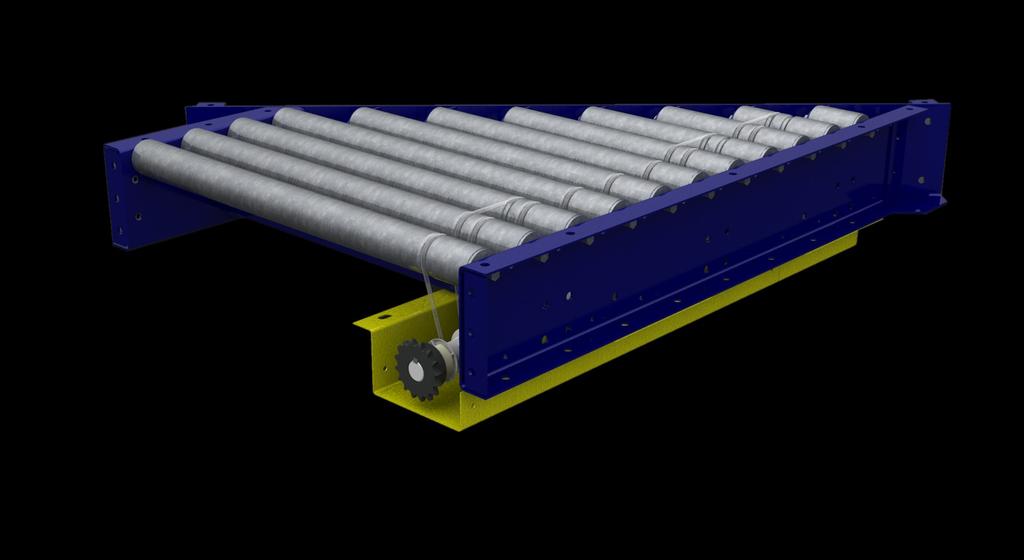
11 SAFETY INFORMATION: ABOUT LINESHAFT DEFINITION Lineshaft driven live roller conveyors are a unique concept in powered conveyors. The basic design employs rollers which are independently driven by a urethane drive belt from a common drive shaft. The general operation of the conveyor is a drive shaft that spans the full length of the conveyor and transmits power to the rollers via a drive spool and belt. When back pressure is applied to the conveyed product, the spools driving the rollers under the product will slip on the drive shaft allowing the product to accumulate with a minimum amount of back pressure. ROLLER FLOW DRIVE BELT DRIVE SHAFT (CLOCKWISE) DRIVE SPOOL RETAINING CLIP LINESHAFT CONVEYOR STRAIGHT, CURVE AND SPUR TECH HANDBOOK SAFETY INFORMATION: LINESHAFT SAFETY INSTRUCTIONS LINESHAFT SAFETY INSTRUCTIONS Lineshaft conveyor is a powered conveyor that can only be stopped by cutting power to its motor. Lineshaft conveyor contains many parts including sprockets, spools, shafts, chains, belts and rollers. Any moving part is a potential source of danger; especially to careless or untrained personnel. Although guards are provided to prevent contact with the conveyor s components, all personnel should be instructed in the necessity for continuous care and attention to safety in the operation of a conveyor. PARTICULAR DANGER AND PINCH POINTS 1) Any point at which a belt bends around a roller or pulley. 2) Any point where two rollers or pulleys are close together and produce a wringer effect. 3) Any point where accessories are located that also have moving parts. 11
 Immediately report shortage or damages to the vendor and carrier. 4) Obtain a signed damage report from the carrier and send a copy to the vendor.")

12 RECEIVING AND INSPECTION: RETURNS, DAMAGES AND SHORTAGES UNCRATING CHECKLIST 1) Compare the bill of lading with what you have received (including accessories). 2) Examine the equipment for damage. 3) Immediately report shortage or damages to the vendor and carrier. 4) Obtain a signed damage report from the carrier and send a copy to the vendor. Do not attempt to modify or repair damaged equipment without authorization from vendor. Note: Do not return equipment to the factory without a written return authorization. Returns without written authorization will not be accepted. Single section Multiple sections Note: Custom products may be crated differently to fit the conveyor design. MOTOR DRIVEN ROLLER CONVEYOR STRAIGHT AND CURVE TECH HANDBOOK RECEIVING AND INSPECTION: REMOVAL OF CRATING AFTER COMPLETING THE UNCRATING CHECKLIST 1) Remove crating and packaging. 2) Look for boxes, accessories, bags or components such as fasteners, manuals, guard rails etc. that may be banded or fastened to the crating material. Note: Make sure all fasteners, guards and essential components are not discarded. 12
13 GENERAL INSTALLATION: OVERVIEW 1) Wherever it is possible, installation should begin at one end of a system and continued through until it is complete. This note holds true for both the leveling procedure and the shaft alignment procedure. 2) If any obstructions are present that were overlooked in the system layout, the conveyor may have to be rerouted. If this situation occurs, consider beginning installation at the rerouting point and continue in either direction as necessary. 3) When the lineshaft conveyor system is to travel between different rooms or departments, particular attention must be paid to floor levels in order to achieve proper installation. 4) Never begin installation at opposite ends of a system and work toward the center. Shaft alignment problems are highly likely to occur in this case. 13
 or products will skew and tumble from the conveyor.")
14 GENERAL INSTALLATION: CHECKING UNIT SQUARENESS SQUARING Frame squareness can be checked by using a simple right angle square as shown or by measuring from the same points diagonally, corner to corner. Note: Make sure frames are square (as shown) or products will skew and tumble from the conveyor. Failure to square frames may also cause premature conveyor wear and failure. 14

 Starting at one end of the drive section, begin the assembly of Delrin couplers at each joint.")
 ROLLERS EACH SIDE OF JOINT SLIDE BACK THE SPROCKET (BOTH SIDES) 15 REMOVE PLASTIC SNAP-ON CLIPS (BOTH SIDES) C) Remove the")
15 GENERAL INSTALLATION: COUPLING / ATTACHING BED SECTIONS FRAME COUPLING With the Delrin Chain Coupler removed, couple the frame sections using the supplied fasteners as shown in the drawing below. Note: For ease of installation, mount legs on each conveyor section prior to coupling. DELRIN COUPLINGS 1) Starting at one end of the drive section, begin the assembly of Delrin couplers at each joint. A) Remove two rollers each side of joint. B) Remove snap-on plastic clips from the shaft in the area between the shaft support bearings. REMOVE (2) ROLLERS EACH SIDE OF JOINT SLIDE BACK THE SPROCKET (BOTH SIDES) 15 REMOVE PLASTIC SNAP-ON CLIPS (BOTH SIDES) C) Remove the belts that retain the Delrin couplers and remove the tape from the end of the shaft. D) Slide the sprocket further apart, exposing both ends of the shaft.

 1/4 KEYSTOCK (VERTICAL ADJUSTMENT) HORIZONTAL")


16 GENERAL INSTALLATION: COUPLING / ATTACHING BED SECTIONS E) Using 1/4 inch keystock, check the shaft alignment at 90 degree intervals and adjust for horizontal or vertical misalignment if necessary. 1/4 KEYSTOCK (HORIZONTAL ADJUSTMENT) 1/4 KEYSTOCK (VERTICAL ADJUSTMENT) HORIZONTAL ADJUSTMENT Loosen two bearings each side of joint where they attach to the spreaders. Align the shaft and re-tighten the bearings. Verify alignment. LOOSEN BEARING BOLTS VIEW A LOOSEN BEARING BOLTS VIEW A CORRECT VIEW A INCORRECT VERTICAL ADJUSTMENT Loosen two spreaders each side of joint on the shaft side where they attach to the side frames. Align the shaft and the spreaders. Verify alignment and re-tighten. VIEW B LOOSEN SPREADER BOLTS LOOSEN SPREADER BOLTS VIEW B CORRECT VIEW B INCORRECT VERIFY ALIGNMENT USING A SHORT PIECE OF 1/4 KEYSTOCK OR BY SLIDING SPROCKET FROM ONE SHAFT ONTO THE OTHER F) Tighten one sprocket flush with the end of the shaft. Make sure both set screws are tightened securely. 16


 For Curves A) Repeat Step 1 except primary adjustments should be made in the curve and not in the straight section because there is a greater chance of misalignment due to manufacturing tolerances")
17 GENERAL INSTALLATION: COUPLING / ATTACHING BED SECTIONS G) Move the other sprocket to the end of the shaft. The 1/4 inch keystock should pass between the sprocket faces to establish the distance apart. Tighten the other sprocket. Make sure both set screws are tightened securely. H) Replace the plastic snap-on clips. Wrap Delrin coupling around the sprockets to make sure it fits EASILY over the teeth. If it does not fit easily, see step 1D. DO NOT ASSEMBLE DELRIN CHAIN AT THIS TIME. It will be easier to line up the shafts on future joints if the shaft can turn freely. NOTE: When properly assembled, arrangement should look like this: 2) Repeat Step 1 at every joint. 3) For Curves A) Repeat Step 1 except primary adjustments should be made in the curve and not in the straight section because there is a greater chance of misalignment due to manufacturing tolerances between a curve and a straight than between two straight sections. B) Align and reconnect after all other connections are made. 4) Assemble Delrin chain over the sprockets at every joint. The pin should be pushed in with channel locks (see sketch). DO NOT HAMMER PIN INTO PLACE. This will damage the Delrin coupling. 5) Reassemble the rollers at each joint from Step 1A. 6) Two spool guard end caps and two shaft collars are supplied with every drive section. At the end of the last slaved section, remove the sprocket and key. Bolt in the spool guard end cap. SPOOL GUARD ENDCAP SAFETY WARNING: Replace all safety devices, guards and guarding prior to equipment start-up. 17

 Remove all load from the conveyor. 3) Position conveyor in the location to be installed. 4) Support conveyor section with jack, hoist or forklift.")
 8) Tighten fasteners using torque appropriate for each fastener s size and grade.")
18 LEG SUPPORTS AND INSTALLATION PERMANENT INSTALLATION OF LEGS Secure leg supports to the floor utilizing the lag holes in the adjustable leg boot. SIDE FRAMES Note: Make sure the conveyor is level by placing a level on the conveyor side frames. If the conveyor is not level, adjust the legs appropriately as shown below. LAG HOLES LEG ADJUSTMENT: BOLT-TOGETHER LEGS 1) The conveyor electrical power must be turned off and locked / tagged out following your company s machine specific procedures. 2) Remove all load from the conveyor. 3) Position conveyor in the location to be installed. 4) Support conveyor section with jack, hoist or forklift. 5) Carefully loosen the fasteners within the slots. 6) Lift or lower conveyor until it is at the desired height. 7) Ensure that the conveyor is completely level. (reference leveling note below) 8) Tighten fasteners using torque appropriate for each fastener s size and grade. (grade 5 fasteners provided) HEX HEAD CAP SCREWS PIVOT BRACKET UPRIGHT BOOT Note: Only qualified installation professionals should level and install conveyor. 18
 Attach knee brace angle to the leg support and brace bracket.")


19 KNEE BRACES, CASTERS AND CEILING HANGERS: INSTALLING KNEE BRACES INSTALLING KNEE BRACES 1) After leg supports are set in place, attach the brace bracket. 2) Attach knee brace angle to the leg support and brace bracket. (Knee brace angle may need to be cut, drilled and trimmed for proper fit and to eliminate interference with adjacent equipment) Note: Knee braces are recommended when the conveyor height exceeds 36 and/or when additional stability is needed. DETAIL DESCRIPTION 1 UPRIGHT 2 SPREADER 3 BRACE BRACKET 4 KNEE BRACE ANGLE 5 PIVOT BRACKET 6 FOOT 7 HEX HEAD CAP SCREW MOTOR DRIVEN ROLLER CONVEYOR STRAIGHT AND CURVE TECH HANDBOOK KNEE BRACES, CASTERS AND CEILING HANGERS: INSTALLING CASTERS NOTE: CUSTOMER TO LOCATE AND DRILL IF NECSSARY INSTALLING CASTERS Once in position, casters should be locked until conveyor needs to be moved again. Note: Leg supports with casters follow similar installation instructions as standard leg supports and knee braces. 19 DETAIL DESCRIPTION 1 UPRIGHT 2 SPREADER 3 BRACE BRACKET 4 KNEE BRACE ANGLE 5 PIVOT BRACKET 6 FOOT 7 Z-PLATE 8 PHENOLIC CASTER 9 HEX HEAD CAP SCREW


20 KNEE BRACES, CASTERS AND CEILING HANGERS: INSTALLING CEILING HANGERS INSTALLING CEILING HANGERS When using conveyors in an overhead scenario, mount hangers at section joints. Note: When installing ceiling hangers, refer to local building codes to ensure that materials comply. Only experienced material handling installers should attempt to install conveyors. CONVEYOR SECTION DETAIL DESCRIPTION 1 HANGER CHANNEL 2 PIPE SPREADER 3 THREADED ROD 4 U-BOLT 5 WHIZ NUT 6 HEX HEAD CAP SCREW 7 HEX NUT 8 LOCK WASHER 20
 Lower the conveyor section onto the lower spreader (detail 2) and attach using supplied fasteners. 3) Check for appropriate elevation and attach the knee bracket assembly (detail 3,4,6,7,8).")

21 MULTI-TIER SUPPORTS: INSTALLATION OF MULTI-TIER SUPPORTS INSTALLING MULTI-TIER SUPPORTS 1) Remove the upper spreader (detail 2) from support. 2) Lower the conveyor section onto the lower spreader (detail 2) and attach using supplied fasteners. 3) Check for appropriate elevation and attach the knee bracket assembly (detail 3,4,6,7,8). 4) For upper conveyor assembly, replace upper spreader and repeat steps 2 and 3. 5) Make sure all multi-tier supports are in line and square prior to conveyor start-up. Note: Make sure that the conveyor is stable prior to multi-tier assembly. Use of a forklift or crane may be required to ensure safe handling. Only experienced installation professionals should install conveyor. DETAIL DESCRIPTION 1 UPRIGHT 2 SPREADER 3 BRACE BRACKET 4 KNEE BRACE ANGLE 5 FOOT WELDMENT 6 WHIZ NUT 7 HEX HEAD CAP SCREW 8 FLAT WASHER 21
22 PRE-START-UP OVERVIEW: PREPARING FOR INITIAL START-UP 1) Review pages 7 through 10 prior to starting any equipment. 2) Verify that conveyor sections, leg supports, etc. were installed properly. 3) Verify that drive chains and sprockets are installed, aligned and tensioned properly 4) Verify set screws are tight in sprockets, bearings and all components that have them in. 5) Verify that all drive and mounted bearing bolts are fastened securely. 6) Verify that all motor control wiring is connected properly. 7) Verify that conveyor is not loaded with product. 8) Verify that gearboxes are filled with the proper amount of oil or that they were factory filled with lube. (If your conveyor is equipped with a Boston 700 Series Reducer, it is filled with oil, sealed and lubed for life thus requiring no oil changes. Literature provided with equipment will give detailed info on gearbox lube info) 9) Verify that the gearbox has necessary vent plugs installed if applicable. (If your conveyor is equipped with a Boston 700 Series Reducer, it is supplied with a PosiVent and no vent plug is required. Literature provided with equipment will give detailed info on gearbox vent plug requirements.) 22
23 PRE-START-UP OVERVIEW: DRIVE CHAIN AND SPROCKET ALIGNMENT DRIVE CHAIN AND SPROCKET ALIGNMENT To achieve maximum service life and efficiency from a chain drive, follow these simple guidelines: Visually inspect the roller chain, sprockets, and other components and verify that they are in good condition. Ensure that the sprockets are properly aligned. Adequately lubricate the chain. Inspect for proper chain tension. CONDITION OF COMPONENTS Shafting and bearings should be supported rigidly to maintain the initial alignment. Roller chain should be free of grit and dirt. Wash chain in kerosene when required. Relubricate. DRIVE ALIGNMENT Misalignment results in uneven loading across the width of the chain and may cause roller link-plate and sprocket tooth wear. Drive alignment involves two things: parallel shaft alignment and axial sprocket alignment. ALIGNING SHAFTS Shafts should be parallel and level. If there is axial movement of the shaft (as in the case of an electric motor), lock the shaft in the normal running position before aligning the sprockets. ALIGNING SPROCKETS Sprocket axial alignment can be checked with a straight edge which will extend across the finished sides of the two sprockets. Normally, it is good practice to align the sprockets as close to the shaft bearing as possible. For long center distances, use a taut cord, or wire long enough to extend beyond each of the sprockets. SPROCKET STRAIGHT EDGE SET SCREWS SPROCKET WARNING: Before performing any maintenance, lubrication or inspection on any powered conveyor, the electrical power must be turned off and locked / tagged out following your company s machine specific procedure. NEVER operate the conveyor with any guard removed. 23


24 PRE-START-UP OVERVIEW: DRIVE CHAIN AND SPROCKET TENSION INSTALLING THE CHAIN Recheck all preceding adjustments for alignment and make certain all setscrews, bolts and nuts are tight. Fit chain around both sprockets and bring the free ends together on one sprocket for connection. The sprocket teeth will locate the chain end links. Install the connecting link, connecting link cover plate and the spring clip or cotter pins. On larger pitch chains or heavy multiple strand, it may be necessary to lock the sprockets for this operation. CHAIN TENSION Check chain tension to be certain the slack span has an approximate 2% mid-span movement. CHAIN TOO TIGHT CHAIN TOO LOOSE CORRECT SLACK SPROCKET CENTERS Requires extra power and causes excessive wear Causes excessive wear and excessive noise Approximately 2% of sprocket centers CHAIN DRIVEN LIVE ROLLER CONVEYOR STRAIGHT AND CURVE TECH HANDBOOK PRE-START-UP OVERVIEW: GEAR REDUCER VENT PLUG PosiVent Omni Metalcraft Corp. standardly supplies the Boston Gear PosiVent option for all current 700 series styles and configurations. This specially-designed internal pressure equalization system allows the gearbox to operate in all environments without the use of conventional pressure vents. The unique design comes complete with Klubersynth UH lubrication pre-filled for all mounting positions. Unlike competitive versions, this unique single seam design allows for easy installation and extended life. This means longer trouble-free operation with virtually no maintenance. 24

25 MAINTENANCE: INSPECTION AND LUBRICATION CARE AND MAINTENANCE OF CHAIN Proper maintenance of any chain should include correct lubrication, periodic inspection and proper adjustment for normal wear. Periodic inspection of the chain and sprockets is required to detect any deviation from normal wear before serious damage takes place. The cost of such inspection is repaid many times in extended chain life and in freedom from failure. No general rule can be given for the frequency of inspection. The frequency should be influenced by conditions of operation. CHAIN LUBRICATION AND ENVIRONMENT One of the most important factors in getting the best possible performance out of our drive chain is proper lubrication. A well lubricated chain will have an operating life much longer than that of an unlubricated chain. Wear between the pin and bushing causes drive chain to elongate. These parts should, therefore, be well lubricated. The gap between the roller link plate and the pin link plate on the slack side of the chain should be filled with oil. This oil forms a film which minimizes wear on the pin and bushing, thus increasing the chain s service life. It also reduces noise and acts as a coolant when the chain runs at high speeds. PIN LINK PLATE Clean Atmosphere: Chains operating in a relatively clean atmosphere can be lubricated by brush or dripfeed oilers or by applying the lubricant manually with a brush or oil can. Atmosphere with Lint or Non-Abrasive Dust: Where large volumes of lint or non-abrasive dust are present, a brush or wiper can be used to clean the chain and apply a lubricant. Otherwise the lint or dust will clog the chain joint clearance and prevent penetration of the oil into the joints. Abrasive Atmosphere: If abrasives come in contact with chain, lubrication becomes more difficult. When lubricants are applied externally, abrasive particles tend to adhere to the chain surfaces and act as a lapping or grinding compound. Under extreme conditions it is sometimes advisable to avoid chain lubrication. Extreme Conditions: Consult a lubricant manufacturer when chains are required to operate at temperatures outside of those indicated in the chart below or if chains are used in other extreme conditions. SUGGESTED LUBRICATION Only high quality oil should be used to lubricate chain. Neither heavy oil nor grease is suitable. The lubricant should have a viscosity to enable it to reach internal surfaces under normal conditions. Lubricants suggested for specific ambient temperatures and chain speed ranges are given in the table below. TEMPERATURE CHAIN NUMBER F F F F ANSI SAE10W SAE20 SAE30 SAE40 ANSI SAE20 SAE30 SAE40 SAE50 ANSI SAE30 SAE40 SAE50 4" & 6" PITCH (ENGINEERED CHAIN) SAE20 SAE30 SAE40 PIN ROLLER ROLLER LINK PLATE BUSHING 25
26 MAINTENANCE: MAINTENANCE SCHEDULES Note: Review pages 9 and 10 prior to maintaining any equipment. If equipment repair or replacement is required during inspections, thoroughly review the manufacturer s specific product information for correct procedure. DAILY MAINTENANCE Inspect all conveyors to ensure that all guarding is securely in place. WEEKLY MAINTENANCE Inspect bearings, gear reducers, motors and chains for excessive noise. MONTHLY MAINTENANCE Inspect oil level in reducer. Fill if necessary. Inspect reducer for leaking seals. Inspect conveyor for loose bolts. Inspect drive chains, jump chains and sprockets for wear, alignment and proper chain tension. For chain lubrication see page 25. QUARTERLY MAINTENANCE Grease all U-joints in curves. Remove rollers in area of U-joint. Then remove finger guard plate over U-joint to gain access to grease fitting. Inspect conveyors for worn or broken drive belts. Replace as necessary. If belt shows signs of abrasion, check for hindrance with the belt or foreign object in the roller groove. SEMI-ANNUAL MAINTENANCE Tighten all bearing set screws if not completely tight. ANNUAL MAINTENANCE Change oil in reducers. (If your conveyor is equipped with a Boston 700 Series Reducer, it is filled with oil, sealed and lubed for life thus requiring no oil changes. See manufacturer s information for recommended lubricant at specific temperatures. This information is shipped with every reducer.) 26
27 MAINTENANCE: REPORT ON MISCELLANEOUS MAINTENANCE PERFORMANCE REPORT ON MISCELLANEOUS MAINTENANCE PERFORMANCE Date Maintenance Performed: Date Maintenance Performed: Date Maintenance Performed: Date Maintenance Performed: Date Maintenance Performed: Date Maintenance Performed: Date Maintenance Performed: 27
28 TROUBLESHOOTING AND REPLACEMENT PARTS: TROUBLESHOOTING PROBLEM CAUSE SOLUTION Not enough rollers being driven Drive more rollers, if available Poor bottoms on product Improve conveyability Overloading product Remove overload Lubricant on drive shaft Clean shaft with liquid degreaser Insufficient Drive Lubricant on belts, rollers and drive Clean belts, rollers and pulleys pulleys Weak belt (see Weak Belts) Replace belts Interference Locate and correct interface Reaction to chemical Correct cause Weak Belts Excessive temperature Replace belt Ultraviolet rays (sun) Replace belt Weak belt (see Weak Belts) Replace belts Bad bearings in rollers Replace rollers Rollers Not Turning or Turning Interference with roller or belt Remove interference Slowly Roller bent Replace roller Belt rubbing on interference Correct cause Poor belt joint (replacement belt) Replace belt Broken Belt Belt rubbing on interference Correct cause Poor belt joint (replacement belt) Replace belt Drive shaft location Move shaft Belt Out of Groove Very dry conditions Lightly oil groove Groove mislocated Replace roller Misalignment in bearings Loosen bearing and readjust shaft Bent shaft Replace shaft Vibration in Drive Shaft Misalignment in couplings Realign coupling Key one end of center shaft in Universal out of phase alignment with opposite key Equalize angles Pulsation After Curve or Merge Angle of universal not equal Readjust coupling Drive Shaft Bearing Noisy Misaligned drive shaft Loosen bearing Bad bearings Replace bearing Insufficient lubricant Add recommended oil Output shaft or chain rubbing chain Reducer or Motor Noisy guard Adjust guard Bent fan housing, worn brushes and worn bearing Repair or replace part Broken Coupler Chain Improper chain installation Replace chain Misalignment Realign shafts Over filling Drain lubricant to proper level Reducer Oil Leakage Vent in wrong location Place vent in uppermost position Extend vent with pipe nipple Tighten all bolts and fittings Worn Seal Replace seal Loose chain Tighten chain Sprocket Wear Misalignment Check alignment with straight edge along side of chain Running dry Lubricate 28
29 TROUBLESHOOTING AND REPLACEMENT PARTS: TROUBLESHOOTING PROBLEM CAUSE SOLUTION Wrong size overloads Use proper size overloads Start Overloads Kicking Out Motor too small Replace motor with proper size Defective motor Replace motor Non-Symmetrical Wear on Wear on Inside of Roller Plates or Side of Sprocket Teeth Wear on Tips of Sprocket Teeth Broken Chain Parts or Sprocket Teeth Excessive Chain Noise Shafts out of parallel or not in same Sprockets offset on shaft (misaligned) or out of parallel Chain elongated excessively Loose chain Drive overloaded Excessive slack causing chain to jump teeth Foreign object Inadequate lubrication Corrosion Chain contacting fixed objects Inadequate lubrication Broken or missing rollers Shaft and sprocket misalignment Chain jumping sprocket teeth Realign sprockets Realign sprockets Replace chain Tighten chain Avoid overloading Periodically adjust center distance Remove object and prevent entry Maintain proper lubrication intervals Remove source of corrosion or use non-corrosive chain Remove objects Maintain proper lubrication intervals Repair or replace chain Realign Adjust center distance between sprockets, tightening the chain 29


30 PARTS LISTS: LINESHAFT STRAIGHT DETAIL DESCRIPTION DETAIL DESCRIPTION 1 SIDEFRAME 19 DRIVEN SPROCKET 2 BOLT-IN SPREADER 20 COUPLER SPROCKET 3 END COUPLER 21 DRIVE CHAIN 4 GROOVED ROLLER: 1 GROOVE 22 COUPLING CHAIN 5 GROOVED ROLLER: 2 GROOVES 23 CHAIN GUARD: BACK 6 URETHANE DRIVE BELT 24 CHAIN GUARD: FRONT 7 URETHANE SLAVE BELT 25 FINGER GUARD 8 DRIVE SHAFT 26 SLOT GUARD 9 SPOOL 27 SPOOL GUARD: SHORT SECTION 10 SPOOL SPACER 28 SPOOL GUARD: LONG SECTION 11 PEER PILLOW BLOCK BEARING 29 SPOOL GUARD END CAP 12 REDUCER CARRIAGE PLATE 30 KEYSTOCK 13 VERTICAL TAKE-UP PLATE 31 HEX HEAD CAP SCREW 14 DRIVE SUPPORT CHANNEL 32 CARRIAGE BOLT 15 CHANNEL SPREADER 33 SELF TAPPING SCREW 16 MOTOR 34 HEX NUT 17 REDUCER 35 WHIZ NUT 18 DRIVE SPROCKET 30

31 PARTS LISTS: LINESHAFT CURVE DETAIL DESCRIPTION 1 OUTSIDE RAIL 2 INSIDE RAIL 3 BOLT-IN SPREADER 4 END COUPLER: OUTSIDE RAIL 5 END COUPLER: INSIDE RAIL 6 GROOVED TAPERED ROLLER: 3 GROOVES 7 URETHANE DRIVE BELT 8 URETHANE SLAVE BELT 9 DRIVESHAFT 10 SPOOL 11 SPOOL SPACER 12 PILLOW BLOCK BEARING 13 U-JOINT 14 BEARING MOUNTING BLOCK 15 CHAIN COUPLING 16 U-JOINT FINGER GUARD 17 COUPLER SPROCKET 18 SPOOL GUARD 19 SPOOL GUARD END CAP 20 FRONT GUARD 21 HEX HEAD CAP SCREW 22 CARRIAGE BOLT 23 WHIZ NUT 31

32 PARTS LISTS: LINESHAFT CURVE WITH TANGENT (30 shown) DETAIL DESCRIPTION 1 TANGENT SIDEFRAME 2 OUTSIDE RAIL 3 INSIDE RAIL 4 BOLT-IN SPREADER 5 END COUPLER 6 GROOVED ROLLER: 1 GROOVE 7 GROOVED TAPERED ROLLER: 3 GROOVES 8 URETHANE DRIVE BELT 9 URETHANE SLAVE BELT 10 DRIVE SHAFT 11 SPOOL 12 SPOOL SPACER 13 PEER PILLOW BLOCK BEARING 14 U-JOINT 15 BEARING MOUNTING BLOCK 16 COUPLING CHAIN 17 COUPLER SPROCKET 18 SPOOL GUARD: FRONT 19 SPOOL GUARD: BACK 20 SPOOL GUARD: TOP 21 SPOOL GUARD END CAP 22 HEX HEAD CAP SCREW 23 CARRIAGE BOLT 24 HEX NUT 32

33 PARTS LISTS: LINESHAFT SPUR DETAIL DESCRIPTION DETAIL DESCRIPTION 1 SHORT RAIL 17 KEYED SPOOL 2 LONG RAIL 18 SPOOL SPACER 3 BOLT-IN SPREADER 19 PEER PILLOW BLOCK BEARING 4 SPUR SPREADER 20 SHAFT COLLAR 5 END COUPLER 21 COUPLER SPROCKET 6 MOUNTING BRACKET 22 SPOOL GUARD END CAP 7 STABILIZING BRACKET: SHORT RAIL 23 SPOOL GUARD: LONG 8 STABILIZING BRACKET: LONG RAIL 24 SPOOL GUARD: SHORT 9 HEX SUPPORT 25 CHAIN COUPLING 10 SHELF BRACKET 26 KEYSTOCK 11 GROOVED ROLLER: 1 GROOVE 27 HEX HEAD CAP SCREW 12 GROOVED ROLLER: 2 GROOVES 28 CARRIAGE BOLT 13 URETHANE DRIVE BELT 29 SELF TAPPING SCREW 14 URETHANE SLAVE BELT 30 HEX NUT 15 DRIVE SHAFT 31 WHIZ NUT 16 SPOOL 32 FLAT WASHER 33


34 PARTS LISTS: LINESHAFT SPUR RIGHT HAND LEFT HAND 34
35 NOTES Notes: 35
36 ABBREVIATED WARRANTY Omni Metalcraft Corp. warrants that the Equipment will be free of defects in workmanship and material (if properly installed, operated and maintained) for a period of one year or 2080 hours of use, whichever is sooner, from date of shipment to Customer, subject to the limitations hereunder set forth. If within the one year warranty period, Omni receives from the Customer written notice of any alleged defects in the Equipment and if the Equipment is not found to be in conformity with this warranty (the Customer having provided Omni a reasonable opportunity to perform any appropriate tests thereon) Omni will, at its option, either repair the Equipment or supply a replacement therefore. *The above stated information is in reference to a section of Omni Metalcraft s full Terms and Conditions of sale. This information does not constitute an agreement, but simply reference information. To obtain a full copy of Omni Metalcraft s Terms and Conditions of Sale, please contact your Sales Representative. 36

37 37
CHAIN DRIVEN LIVE ROLLER CONVEYOR STRAIGHT AND CURVE TECH HANDBOOK TABLE OF CONTENTS
 TABLE OF CONTENTS TABLE OF CONTENTS... 2 GENERAL SAFETY STATEMENTS... 3 -Introduction... 3 -Cautions, Warnings and Hazards... 3 SAFETY INFORMATION... 4 -Safety Labels... 4, 5 -Installation Safety... 6
BELT TECHNICAL HANDBOOK
 1 TABLE OF CONTENTS TABLE OF CONTENTS... 2, 3 GENERAL SAFETY STATEMENTS... 4 -Introduction... 4 -Cautions, Warnings and Hazards... 4 SAFETY INFORMATION... 5 -Safety Labels... 5, 6 -Installation Safety...
TURNTABLE TECHNICAL HANDBOOK TURNTABLE TECHNICAL HANDBOOK
 1 TABLE OF CONTENTS TABLE OF CONTENTS... 2 GENERAL SAFETY STATEMENTS... 3 -Introduction... 3 -Cautions, Warnings and Hazards... 3 SAFETY INFORMATION... 4 -General Safety Labels... 4, 5 -Installation Safety...
INSTALLATION AND MAINTENANCE MANUAL DRAG CHAIN CONVEYOR MODEL DC-60
 INSTALLATION AND MAINTENANCE MANUAL DRAG CHAIN CONVEYOR MODEL DC-60 Version 2014.1 - - TABLE OF CONTENTS INTRODUCTION Receiving, Inspection and Uncrating... 3 Ordering Replacement Parts... 3 SAFETY INFORMATION
INSTALLATION AND MAINTENANCE MANUAL TROUGH BELT CONVEYOR MODEL TBOH
 INSTALLATION AND MAINTENANCE MANUAL TROUGH BELT CONVEYOR MODEL TBOH Version 2014.1 - - TABLE OF CONTENTS INTRODUCTION Receiving, Inspection and Uncrating... 3 Ordering Replacement Parts... 3 SAFETY INFORMATION
INSTALLATION AND MAINTENANCE MANUAL BELT CONVEYOR MODEL BS100B
 INSTALLATION AND MAINTENANCE MANUAL BELT CONVEYOR MODEL BS100B Version 2014.1 - - TABLE OF CONTENTS INTRODUCTION Receiving, Inspection and Uncrating... 3 Ordering Replacement Parts... 3 SAFETY INFORMATION
INSTALLATION AND MAINTENANCE MANUAL BELT DRIVEN LIVE ROLLER CONVEYOR
 INSTALLATION AND MAINTENANCE MANUAL BELT DRIVEN LIVE ROLLER CONVEYOR Version 2014.1 - - TABLE OF CONTENTS INTRODUCTION Receiving, Inspection and Uncrating... 3 Ordering Replacement Parts... 3 SAFETY INFORMATION
INSTALLATION AND MAINTENANCE MANUAL ROLLER BED BELT CONVEYOR MODEL BR100C & BRI
 INSTALLATION AND MAINTENANCE MANUAL ROLLER BED BELT CONVEYOR MODEL BR100C & BRI Version 2014.1 - - TABLE OF CONTENTS INTRODUCTION Receiving, Inspection and Uncrating... 3 Ordering Replacement Parts...
INSTALLATION AND MAINTENANCE MANUAL V-BELT DRIVEN LIVE ROLLER CONVEYOR
 INSTALLATION AND MAINTENANCE MANUAL V-BELT DRIVEN LIVE ROLLER CONVEYOR MODEL VBS19, VBC19, VBCS19 AND VB SS19 VBC19 VBS19 VBS19 VBCS19 VBS19 Version 2014.1 - - TABLE OF CONTENTS INTRODUCTION Receiving,
Installation and Maintenance Manual with Safety Information and Parts List
 IMPORTANT! DO NOT DESTROY Installation and Maintenance Manual with Safety Information and Parts List RECOMMENDED SPARE PARTS HIGHLIGHTED IN GRAY Model C Effective November, 1998 (Supercedes January, 1995)
Before equipment use, please read this operation manual carefully. Serial Number: Date Purchased:
 Pushed & Geared Trolleys OPERATION MANUAL This operation manual is intended as an instruction manual for trained personnel who are in charge of installation, maintenance, repair etc. Before equipment use,
TECH HANDBOOK CHAIN DRIVEN LIVE ROLLERS 192CDLR.251CDLR.297CDLR.3530CDLR
 CHAIN DRIVEN LIVE ROLLERS TECH HANDBOOK 192CDLR.251CDLR.297CDLR.3530CDLR Installing and Maintaining Your Roach Conveyor DO NOT OPERATE BEFORE READING THIS HANDBOOK Important Safety Information Enclosed
443 / M440 Series Lineshaft Driven Live Roller Conveyor Installation and Maintenance Manual
 443 / M440 Series Lineshaft Driven Live Roller Conveyor Installation and Maintenance Manual Metzgar Conveyor Co. - 2010 METZGAR CONVEYORS SAFETY PRECAUTIONS WARNING: DO NOT ATTEMPT MAINTENANCE ON ANY CONVEYORS
OPERATOR MANUAL Combo Belt Conveyor
 1 OPERATOR MANUAL Combo Belt Conveyor Document No. 11-01, Rev., 0816 2 WARNINGS THIS CONVEYOR IS DESIGNED FOR A SPECIFIC APPLICATION. CHECK FRAME AND METAL BELT FOR DAMAGE DURING SHIPMENT. READ THE MANUAL
Wallace Tri-Adjustable Gantry Cranes Square Tube Assembly Instructions
 Wallace Tri-Adjustable Gantry Cranes Square Tube Assembly Instructions For any additional information, Please call 1- S 1. Read and understand instructions before using this gantry. 2. Inspect gantry thoroughly
Jet Fans. Instruction Manual READ AND SAVE THESE INSTRUCTIONS WARRANTY
 Jet Fans Instruction Manual READ AND SAVE THESE INSTRUCTIONS WARRANTY All Leader Fan products are guaranteed to be free from defects of workmanship or material and to function satisfactorily when properly
TECH HANDBOOK FOR LINE SHAFT CONVEYORS TABLE OF CONTENTS
 TECH HANDBOOK FOR LINE SHAFT CONVEYORS TABLE OF CONTENTS LINE SHAFT CONVEYOR TECH HANDBOOK... 2 -Caution Labels... 2 CAUTIONS, WARNINGS AND HAZARDS... 3 -Introduction... 3 -Cautions, Warnings and Hazards...
READ AND SAVE THESE INSTRUCTIONS. Centrifugal Downblast Exhaust Fan Belt Driven for Roof & Wall Mounting
 READ AND SAVE THESE INSTRUCTIONS INSTALLATION, OPERATING INSTRUCTIONS & PARTS MANUAL Centrifugal Downblast Exhaust Fan Belt Driven for Roof & Wall Mounting Electrical wiring and connections should be done
750 Series Press Conveyor Installation and Maintenance Manual
 750 Series Press Conveyor Installation and Maintenance Manual Metzgar Conveyor Co. - 2010 METZGAR CONVEYORS SAFETY PRECAUTIONS WARNING: DO NOT ATTEMPT MAINTENANCE ON ANY CONVEYORS WHILE IN OPERATION. BEFORE
INSTALLATION, OPERATION AND MAINTENANCE MANUAL WALL EXHAUST FANS BELT & DIRECT DRIVE XB, HV, HVA, ADD, DDS, DDP
 INSTALLATION, OPERATION AND MAINTENANCE MANUAL WALL EXHAUST FANS BELT & DIRECT DRIVE XB, HV, HVA, ADD, DDS, DDP The purpose of this manual is to aid in the proper installation and operation of the fans.
2 TON CAPACITY PROFESSIONAL SERIES ALUMINUM JACK OWNER'S MANUAL SPECIFICATIONS
 80006 OWNER'S MANUAL CONTENTS: Page 1 Specifications 2 Warning Information 3 Setup, Operating and Preventative Maintenance 4 Troubleshooting 5 Maintenance 6 Exploded View Drawing and Replacement Parts
DIAMOND CHAIN COMPANY INC. Maintenance Guide
 Maintenance Guide 2006 BULLETIN 1067 TABLE OF CONTENTS ORDERING INFORMATION 3 INSTALLATION 4 LUBRICATION 5 INSPECTIONS 6 ELONGATION LIMITS 7 WHAT IS CHAIN WEAR? Did you know Chain does not STRETCH? Chain
Outload Trough Roller Conveyor
 Outload Trough Roller Conveyor OWNER'S MANUAL 00003400 (8/99) Table of Contents Warranty Information.............................. Inside Front Cover Operator Qualifications / Sign Off Sheet..............................
INSTALLATION, OPERATION AND MAINTENANCE MANUAL WALL EXHAUST FANS BELT DRIVE XBL FANS
 INSTALLATION, OPERATION AND MAINTENANCE MANUAL WALL EXHAUST FANS BELT DRIVE XBL FANS The purpose of this manual is to aid in the proper installation and operation of the fans. These instructions are intended
FTFR Maintenance and Parts Manual SQ-1 FLOOR TRUSS FINISH ROLLER. Operators Manual
 FTFR Maintenance and Parts Manual SQ-1 FLOOR TRUSS FINISH ROLLER Operators Manual FOREWORD This manual explains the proper maintenance of Square 1 Design Floor Truss Finish Roller as well as the daily
6602LP CAPACITY: 2 TON LOW RIDER SERVICE JACK
 CONTENTS: Page 1 Specifications 2 Warning Information 3 Setup Instructions 4 Operating Instructions, Preventative Maintenance, Inspection and Proper Storage 5 Hydraulic Jack Maintenance Guide and Regular
Gantry System for both Floor and Roof Truss Lines SQ-1 INTELLIGENT GANTRY. Operators Manual
 Gantry System for both Floor and Roof Truss Lines SQ-1 INTELLIGENT GANTRY Operators Manual FOREWORD This manual explains the proper maintenance of Square 1 Design Gantry Rollers as well as the daily lubrication
TECH HANDBOOK MODELS 796RBF 700SBF
 INCLINED BELT CONVEYORS TECH HANDBOOK MODELS 796RBF 700SBF Installing and Maintaining Your Roach Conveyor DO NOT OPERATE BEFORE READING THIS HANDBOOK Important Safety Information Enclosed KEEP IN SAFE
BOILER FEED SYSTEM OPERATION AND MAINTENANCE MANUAL
 BOILER FEED SYSTEM OPERATION AND MAINTENANCE MANUAL IMPORTANT These instructions are intended as a guide for the Installing Contractor and as a reference for the Operator, Owner and Serviceman. RETAIN
610 BUSHEL MANURE SPREADER
 610 BUSHEL MANURE SPREADER RODA MANUFACTURING 1008 LOCUST ST. HULL, IA. 51239 Art s-way Manufacturing 712-439-2366 Co., Inc. Hwy 9 West - PO Box 288 WWW.RODAMFG.COM Armstrong, IA. 50514 U.S.A 2 INTRODUCTION
Maintenance and Repair
 Maintenance and Repair WARNING ALWAYS shut off the engine, remove key from ignition, make sure the engine is cool, and disconnect the spark plug and positive battery terminal from the battery before cleaning,
PO W ERCO N H A N D LIN G SYST EM S (PT Y) LT D.
 LT D.") POWERCON CR MONORAIL SYSTEM GUIDE About us: POWERCON HANDLING SYSTEMS specialises in complete overhead monorail conveyors as well as complete Turnkey Operation and Factory Automation projects. Established
POWERCON CR MONORAIL SYSTEM GUIDE About us: POWERCON HANDLING SYSTEMS specialises in complete overhead monorail conveyors as well as complete Turnkey Operation and Factory Automation projects. Established
jegs.com. Installation Instructions for Ton Aluminum Floor Jack
 Installation Instructions for 80077 3-Ton Aluminum Floor Jack Contents: Specifications Warning Information Setup and Operating Instructions Preventive Maintenance and Troubleshooting Hydraulic Maintenance
HYDRAULIC SPREADER. Max. Pressure: 10,000 PSI (700 BAR) Unit Weight: HS2000 = 4.8 LBS. (2.17 Kg) HS3000 = 22 LBS. (9.98 Kg)
 Unit Weight: HS2000 = 4.8 LBS. (2.17 Kg) HS3000 = 22 LBS. (9.98 Kg)") Form No. 103525 Operating Instructions for: HS2000 HS3000 HYDRAULIC SPREADER Max. Pressure: 10,000 PSI (700 BAR) Unit Weight: HS2000 = 4.8 LBS. (2.17 Kg) HS3000 = 22 LBS. (9.98 Kg) Definition: Hydraulic
Form No. 103525 Operating Instructions for: HS2000 HS3000 HYDRAULIC SPREADER Max. Pressure: 10,000 PSI (700 BAR) Unit Weight: HS2000 = 4.8 LBS. (2.17 Kg) HS3000 = 22 LBS. (9.98 Kg) Definition: Hydraulic
450 Series Belt Driven Live Roller Curve Conveyor Installation and Maintenance Manual
 450 Series Belt Driven Live Roller Curve Conveyor Installation and Maintenance Manual Metzgar Conveyor Co. - 2010 METZGAR CONVEYORS SAFETY PRECAUTIONS WARNING: DO NOT ATTEMPT MAINTENANCE ON ANY CONVEYORS
Flip - Up Conveyor. for 10" BeltVeyors OWNER'S MANUAL (12/00)
") Flip - Up Conveyor for 10" BeltVeyors OWNER'S MANUAL 19023100 (12/00) Table of Contents Warranty Information............................ Inside Front Cover Operator Qualifications........................................
Flip - Up Conveyor for 10" BeltVeyors OWNER'S MANUAL 19023100 (12/00) Table of Contents Warranty Information............................ Inside Front Cover Operator Qualifications........................................
MDSB Medium Duty Slider Bed Belt Conveyor
 Owner s Manual MDSB Medium Duty Slider Bed Belt Conveyor LEWCO, Inc. 2016 706 Lane St. Sandusky, Ohio 44870 USA Phone: (419) 625-4014 Fax: (419) 625-1247 Revised 11/11/2016 conveyorsales@lewcoinc.com www.lewcoinc.com
READ AND SAVE THESE INSTRUCTIONS. High Velocity Restaurant-Duty Utility Set Belt Driven for Roof Mounting
 READ AND SAVE THESE INSTRUCTIONS INSTALLATION, OPERATING INSTRUCTIONS & PARTS MANUAL High Velocity Restaurant-Duty Utility Set Belt Driven for Roof Mounting Electrical wiring and connections should be
Installation and Operation Manual. Manufacturers of Innovative Materials Handling Equipment since 1957.
 SWINGSET DISTRIBUTOR Installation and Operation Manual Manufacturers of Innovative Materials Handling Equipment since 1957. 491 North Emerson Street * Cambridge MN 55008-1316 U.S.A. Toll Free (800) 328-8002
INSTALLATION, OPERATION & MAINTENANCE MANUAL AXIAL UPBLAST FANS RTA, RWTA, RHTA, RB, RD, RTA SH
 INSTALLATION INSTALLATION, OPERATION & MAINTENANCE MANUAL AXIAL UPBLAST FANS RTA, RWTA, RHTA, RB, RD, RTA SH The purpose of this manual is to aid in the proper installation and operation of the fans. These
Instruction Sheet. Follower Bar. Compression Roller Assembly (Roller Ass'y/Cylinder Clevis/ Roller Ass'y)
") Gardner Bender Instruction Sheet Model B400, B400D, B400L & B400DL Eegor Hydraulic Benders IMPORTANT RECEIVING INSTRUCTIONS: Visually inspect all components for shipping damage. If any shipping damage
Gardner Bender Instruction Sheet Model B400, B400D, B400L & B400DL Eegor Hydraulic Benders IMPORTANT RECEIVING INSTRUCTIONS: Visually inspect all components for shipping damage. If any shipping damage
Safety, Operation, & Maintenance Manual Douglas CBM Cross Belt Magnetic Separator
 Safety, Operation, & Maintenance Manual Douglas CBM Cross Belt Magnetic Separator Warning: This manual must be read, understood, and followed by anyone that installs, operates, and maintains this product.
TECH HANDBOOK MODEL 796RB & 751RB
 BELT CONVEYORS TECH HANDBOOK MODEL 796RB & 751RB Installing and Maintaining Your Roach Conveyor DO NOT OPERATE BEFORE READING THIS HANDBOOK Important Safety Information Enclosed KEEP IN SAFE PLACE--DO
CAUTION MAINTENANCE INFORMATION CONNECTING AND DISCONNECTING CHAIN
 CONNECTING AND DISCONNECTING CHAIN Introduction Chains are manufactured with connectors, either pins or rivets of various constructions depending upon the chain type, i.e., offset or straight sidebar,
GANTRY ROLLER MANUAL MODELS: G14-24 G14-18 GR14-24 G2640 VOLUME 1, EDITION
 GANTRY ROLLER MANUAL MODELS: G14-24 G14-18 GR14-24 G2640 VOLUME 1, EDITION 5 7-13-04 FOREWORD This manual explains the proper maintenance of Klaisler Gantry Rollers as well as the daily lubrication and
Service Jacks. No. 1503A Max. Capacity: 2-1/2 Tons No. 1504A Max. Capacity: 3 Tons. Service Jack Item List
 SPX Corporation 655 Eisenhower Drive Owatonna, MN 55060-0995 USA Phone: (507) 455-7000 Tech. Serv.: (800) 533-6127 Fax: (800) 955-8329 Order Entry: (800) 533-6127 Fax: (800) 283-8665 International Sales:
MAINTENANCE - LPX PORTABLE TREATER
 MAINTENANCE - LPX PORTABLE TREATER Proper maintenance of the Portable LPV Treater is critical for peak performance, reliability and accuracy of this system. The following is a guideline for the type of
TECH HANDBOOK BELT DRIVEN LIVE ROLLER CURVES/SPURS MODEL 138LRC 196LRC 138LRCS 196LRCS. Installing and Maintaining Your Roach Conveyor
 BELT DRIVEN LIVE ROLLER CURVES/SPURS TECH HANDBOOK MODEL 138LRC 196LRC 138LRCS 196LRCS Installing and Maintaining Your Roach Conveyor DO NOT OPERATE BEFORE READING THIS HANDBOOK Important Safety Information
TWO-STAGE HYDRAULIC PUMP. RWP55-IBT-Air
 ORIGINAL INSTRUCTIONS Form No.1000458 5 SPX Corporation 5885 11th Street Rockford, IL 61109-3699 USA Tech. Services: (800) 477-8326 Fax: (800) 765-8326 Order Entry: (800) 541-1418 Fax: (800) 288-7031 Internet
6722 Rev. A CAPACITY: 22 TON TRUCK AXLE JACK WITH AIR RETURN
 CONTENTS: Page Specifications 2 Warning Information Setup Instructions and Operating Instructions 4 Preventative Maintenance, Inspection and Proper Storage 5 Troubleshooting, Owner/User Responsibility
Instruction Sheet. Follower Bar. Compression Roller Assembly (Roller Ass'y/Cylinder Clevis/ Roller Ass'y)
") Gardner Bender Instruction Sheet Model B400, B400D, B400L & B400DL Eegor TM Hydraulic Benders IMPORTANT RECEIVING INSTRUCTIONS: Visually inspect all components for shipping damage. If any shipping damage
Gardner Bender Instruction Sheet Model B400, B400D, B400L & B400DL Eegor TM Hydraulic Benders IMPORTANT RECEIVING INSTRUCTIONS: Visually inspect all components for shipping damage. If any shipping damage
Vertical Stacking System for both Floor and Roof Lines. SQ-1 INTELLIGENT STACKERS. Operators Manual
 Vertical Stacking System for both Floor and Roof Lines. SQ-1 INTELLIGENT STACKERS Operators Manual FOREWORD This manual explains the proper maintenance of Square 1 Design Intelligent Stacking System as
60 Series End-Mount Brake Instructions Standard Housing
 Bulletin No. BK4655 (04/18) 60 Series End-Mount Brake Instructions Standard Housing Read carefully before attempting to assemble, install, operate or maintain the product described. Protect yourself and
Mechanical Actuators
 Mechanical Actuators Translating Machine Screw Actuators 100-Ton, 150-Ton & 250-Ton Capacity Installation, Operation & Maintenance Instructions Publication Part No. SK-2389-100 CAUTION This manual contains
Signature Overhead System INSTALLATION MANUAL
 Signature Overhead System TM INSTALLATION MANUAL PACLINE Installation Manual Read All Instructions Carefully Proper installation is not difficult, and by adhering to the following procedures the conveyor
INSTRUCTION MANUAL. Anchor Darling 1878 Swing Check Valves. Installation Operation Maintenance. Sizes 1/2 through 2 FCD ADENIM
 INSTRUCTION MANUAL Anchor Darling 1878 Swing Check Valves Sizes 1/2 through 2 Installation Operation Maintenance FCD ADENIM0006-00 Table of Contents 1.0 Physical Description and Operation of Equipment
PO Box 645, Stockton, Missouri, FAX superiorgearbox.com W D0446-A 4/1/05 1
 W000-7000-D0446-A 4/1/05 1 SAFETY PRECAUTIONS CAUTION Please read this entire document prior to operating the gear drive. Gear drive failure and / or injury to operators may be caused by improper installation,
Maintenance Information
 (Dwg. MHP1539) 16600470 Edition 1 May 2007 Z Rail Aluminum and Steel Overhead Rail System Maintenance Information Save these Instructions The minimum maintenance required for a rail system requires inspection
DIAMOND ROLLER CHAIN. For Agricultural and Construction Equipment
 DIAMOND ROLLER CHAIN For Agricultural and Construction Equipment FABRICATION While roller chain would appear to be a simple product, the number of components in a ten foot section of 40 pitch chain totals
Maintenance Instructions
 General Note These instructions contain information common to more than one model of Bevel Gear Drive. To simplify reading, similar models have been grouped as follows: GROUP 1 Models 11, 0, 1,, (illustrated),,
KLAISLER MANUFACTURING CORPORATION
 KLAISLER MANUFACTURING CORPORATION FINISH ROLLER MANUAL MODELS: TR210-24 TR214-24 TR216-24 TR212-24 TR215-24 VOLUME 1, EDITION 4 7/15/04 FOREWORD This manual explains the proper maintenance of Klaisler
TECH HANDBOOK BELT CONVEYORS MODEL 725TB 700SB 700BSB 450BOS. DO NOT OPERATE BEFORE READING THIS HANDBOOK Important Safety Information Enclosed
 BELT CONVEYORS TECH HANDBOOK MODEL 725TB. 700SB. 700BSB Installing and Maintaining Your Roach Conveyor DO NOT OPERATE BEFORE READING THIS HANDBOOK Important Safety Information Enclosed KEEP IN SAFE PLACE--DO
SINGLE BLADE ROOF CUTTER
 Phone: 404-766-7027 Fax: 404-766-7277 www.eastpointequipment.com SINGLE BLADE ROOF CUTTER OPERATING INSTRUCTIONS READ THE INSTRUCTIONS You have purchased a quality piece of roofing equipment. This equipment
201 Series Portable Drum Rotators Operator s Manual for Morse Portable Drum Rotators
 Contents Page Receiving Procedures.................... 1 Warranty............................. 1 Safety Information..................... 1-2 Machine Description................... 3 Options.............................
Instruction Manual AVTM for. Strip Chart Recorder Catalog Nos and
 AVTM220003 Rev. B January 2003 Instruction Manual AVTM220003 for DC µa Strip Chart Recorder Catalog Nos. 220003 and 220003-47 PO Box 9007 Valley Forge, PA 19485-1007 U.S.A. 610-676-8500 Shipping Address:
Safe Operating Practices & Maintenance Manual
 tcamerican.com sales@tcamerican.com 763-479-7000 11110 Industrial Circle NW, Suite A, Elk River, MN 55330 Safe Operating Practices & Maintenance Manual Section Subject Page A. General 2 B. Operator Qualifications
PACKING, HANDLING, TRANSPORTING AND STORING MOTORS
 PACKING, HANDLING, TRANSPORTING AND STORING MOTORS Make sure that the shaft of the motor is not loaded in any way and is protected from knocks. Axial loads or shocks may easily damage the bearings inside
Twin Screw Undercar Conveyor
 Twin Screw Undercar Conveyor Owner s Manual #19015700 05-00 Table of Contents Operator Qualifications...................................... 1 Safety.................................................. 2-4
48" and 52" Hyflo Fans Installation and Operators Instruction Manual
 48" and 52" Hyflo Fans Installation and Operators Instruction Manual Thank You The employees of Chore-Time Equipment would like to thank your for your recent Chore-Time purchase. If a problem should arise,
INSTRUCTION MANUAL 16K - Fifth Wheel Hitch
 You can take it with you. INSTRUCTION MANUAL 16K - Fifth Wheel Hitch Product No. 30047 DEALER/INSTALLER: END USER: (1) Provide this Manual to end user. (2) Physically demonstrate hitching and unhitching
Installation, Operation & Maintenance Manual
 LEWCO, Inc. 706 Lane Street Sandusky, Ohio 44870 Phone 419.625.4014 Fax 419.625.1247 www.lewcoinc.com Installation, Operation & Maintenance Manual Model 40SB Low Profile Slider Bed Belt Conveyor Effective:
PO Box 645, Stockton, Missouri, FAX superiorgearbox.com
 I000-7000-D0447-A 4/7/05 1 SAFETY PRECAUTIONS CAUTION Please read this entire document prior to operating the gear drive. Gear drive failure and / or injury to operators may be caused by improper installation,
7400 Series End Drive Conveyors
 700 Series End Drive Conveyors Installation, Maintenance and Parts Manual Flat Belt Conveyor Cleated Belt Conveyor DORNER MFG. CORP. INSIDE THE USA OUTSIDE THE USA P.O. Box 0 975 Cottonwood Ave. TEL: -800-97-866
INSTRUCTION MANUAL FOR MODEL PRC POWER ROLLER CONVEYOR
 INSTRUCTION MANUAL FOR MODEL PRC POWER ROLLER CONVEYOR - 1 - TABLEOFCONTENTS 1. OPERATION 3 1.1. GENERAL DESCRIPTION 3 1.2. OPERATION 3 1.2.1. GENERAL INSTRUCTIONS 3 2. MAINTENANCE 4 2.1. CHAIN TAKEUP
Pacific Conveyors Ltd INSTALLATION AND MAINTENANCE MANUAL MODEL 914SB BAGGAGE CONVEYORS
 Pacific Conveyors Ltd INSTALLATION AND MAINTENANCE MANUAL MODEL 914SB BAGGAGE CONVEYORS SECTION 1. SECTION 2. SECTION 3. SECTION 4. SECTION 5. SECTION 6. SECTION 7. SECTION 8. SECTION 9. MAINTENANCE MANUAL
TJ lb Capacity Trailer Jack. 2-in-1 Combo With Swing Back Design. Assembly & Operating Instructions
 TJ1500 1500 lb Capacity Trailer Jack 2-in-1 Combo With Swing Back Design Assembly & Operating Instructions READ ALL INSTRUCTIONS AND WARNINGS BEFORE USING THIS PRODUCT. This manual provides important information
Installation, Operation and Maintenance Manual
 Installation, Operation and Maintenance Manual Rev 7 December 2010 1 P a g e Contents General... 4 Safety... 5 Function of the Conveyor:... 5 Operation, Maintenance, and Service... 5 Safety equipment...
OPERATION SERVICE PARTS TUGIT2. Manually Operated Short Handle Lever Hoist A3140-XXX
 OPERATION SERVICE PARTS TUGIT2 Manually Operated Short Handle Lever Hoist A3140-XXX Sold & Serviced by Morgan Aero 1450 80 th Street SW Everett WA U.S.A. 425/438.9600 SAFETY PRECAUTIONS WARNING! Improper
HYDRAULIC UPENDER MANUAL HYDRAULIC UPENDER MANUAL
 1 TABLE OF CONTENTS TABLE OF CONTENTS... 2 GENERAL SAFETY STATEMENTS... 3 Introduction... 3 Cautions, Warnings and Hazards... 3 SAFETY INFORMATION... 4 General Safety Labels... 4, 5 Installation Safety...
TABLE OF CONTENTS INSTALLATION & OPERATING INSTRUCTION MANUAL FOR MODEL PRC-- POWER ROLLER CONVEYOR
 TABLE OF CONTENTS INSTALLATION & OPERATING INSTRUCTION MANUAL FOR MODEL PRC-- POWER ROLLER CONVEYOR 1. INSTALLATION 2 1.1. GENERAL INSTALLATION 2 1.1.1. Building Connections 3 2. OPERATION 3 2.1. GENERAL
Powered Industrial Truck Safety Program
 Powered Industrial Truck Safety Program 0 TABLE OF CONTENTS Forklift Safety Program 1.0 Overview.. 2 2.0 Purpose....2 3.0 Procedures..2 4.0 Responsibilities. 4 5.0 Training Requirements......5 Appendix
HYDRAULIC SCISSOR LIFT MANUAL HYDRAULIC SCISSOR LIFT MANUAL
 1 TABLE OF CONTENTS TABLE OF CONTENTS... 2 GENERAL SAFETY STATEMENTS... 3 Introduction... 3 Cautions, Warnings and Hazards... 3 SAFETY INFORMATION... 4 General Safety Labels... 4, 5 Scissor Lift Safety
KENCOVE PD100 MANUAL TILT POST DRIVER
 OPERATOR S MANUAL KENCOVE PD100 MANUAL TILT POST DRIVER WWW.KENCOVE.COM 800-536-2683 344 KENDALL RD, BLAIRSVILLE, PA 15717 Table of Contents Specifications/Requirements 1 Introduction 2 Equipment Inspection
COOKSON OWNER'S MANUAL
 COOKSON OWNER'S MANUAL FDO-A10 INDUSTRIAL DUTY FIRE DOOR OPERATOR R L I S T E D 3040233 US CONTROL PANEL SERIAL# OPERATOR SERIAL# 9001.DWG ECN 0959 REV 4 SPECIFICATIONS MOTOR TYPE:...INTERMITTENT HORSEPOWER:...1/8
Amarr SuperFlex. Installation Instructions and Owner's Manual. Entrematic 165 Carriage Court Winston Salem, NC
 Entrematic 165 Carriage Court Winston Salem, NC 27105 www.amarr.com 877-512-6277 Amarr SuperFlex Installation Instructions and Owner's Manual Do not install, operate or service this product unless you
MODEL VBO-HV & VBO UPBLAST PROPELLER ROOF FANS
 READ AND SAVE THESE INSTRUCTIONS 9668-D Heinrich Hertz Drive, San Diego, CA 92154 PH: 619-946-1224 MODEL VBO-HV & VBO UPBLAST PROPELLER ROOF FANS SHIPPING INSPECTION Romlair Model VBO-HV & VBO fans are
Instruction Manual. Maximum Operating Pressure 510 bar
 Single Speed Diesel Power Unit Model HPD11 Maximum Operating Pressure 510 bar ABSOLUTE EQUIPMENT PTY LTD 2/186 Granite Street, GEEBUNG QLD 4034 Australia sales@absoluteequipment.com.au Phone: +61 7 3865
Martin SQC2S Square Mainframe Tensioners
 Martin SQC2S Square Mainframe Tensioners Go to Martin SQC2S Square Mainframe Tensioners web page Operator s Manual M3815 Important MARTIN ENGINEERING HEREBY DISCLAIMS ANY LIABILITY FOR: DAMAGE DUE TO CONTAMINATION
PW Cantilever Lift: Part Number: Instructions and Safety Tips 1200 Ibs Capacity
 www.shoremaster.com 1200 PW Cantilever Lift: Part Number:1017507 Instructions and Safety Tips 1200 Ibs Capacity 1. 2. 3. 4. 5. CAUTION - PUT SAFETY FIRST Before attempting to install or operate this hoist,
READ AND SAVE THESE INSTRUCTIONS. Centrifugal Upblast Exhaust Fan (Standard & High Pressure Exhaust) Belt Driven for Roof & Wall Mounting
 Belt Driven for Roof & Wall Mounting") READ AND SAVE THESE INSTRUCTIONS INSTALLATION, OPERATING INSTRUCTIONS & PARTS MANUAL Centrifugal Upblast Exhaust Fan (Standard & High Pressure Exhaust) Belt Driven for Roof & Wall Mounting Electrical wiring
READ AND SAVE THESE INSTRUCTIONS INSTALLATION, OPERATING INSTRUCTIONS & PARTS MANUAL Centrifugal Upblast Exhaust Fan (Standard & High Pressure Exhaust) Belt Driven for Roof & Wall Mounting Electrical wiring
accidents which arise due to nonobservance and the safety information herein.
 2000LB WINCH Model: 7247 CALIFORNIA PROPOSITION 65 WARNING: You can create dust when you cut, sand, drill or grind materials such as wood, paint, metal, concrete, cement, or other masonry. This dust often
UNPACKING SAFETY GUIDELINES GENERAL SAFETY INFORMATION. Operating Instructions & Maintenance Manual
 Please read and save this Repair Parts Manual. Read this manual and the General Operating Instructions carefully before attempting to assemble, install, operate or maintain the product described. Protect
BOLT-ON AND WELD-ON FLUSH FLOOR SLIDEOUT SYSTEMS OPERATION AND SERVICE MANUAL
 BOLT-ON AND WELD-ON FLUSH FLOOR SLIDEOUT SYSTEMS OPERATION AND SERVICE MANUAL TABLE OF CONTENTS SYSTEM...... Warning........ Description...... Prior to Operation OPERATION... Main Components... Mechanical...
INSTRUCTIONS AND PARTS LIST FOR MODEL 125H & 150H HAND-OPERATED HYDRAULIC PRESS
 INSTRUCTIONS AND PARTS LIST FOR MODEL 125H & 150H HAND-OPERATED HYDRAULIC PRESS SETTING UP THE PRESS FOR OPERATION For shipping convenience, the gauge, pump handle, hoist crank, screw nose and base angles
Emergency Smoke Control Centrifugal Roof Exhaust Fans
 IN THIS SECTION Emergency Smoke Control Centrifugal Roof Exhaust Fans HA~~ISAI~ SYSTEl\t1S, INC. Heat:ing &.-Air Condit:ioning Inst:allat:ion &,-Service -------- READ AND SAVE THESE INSTRUCTIONS [RGREENHECK
IMPORTANT INSTRUCTIONS FOR OPERATION & MAINTENANCE OF
 IMPORTANT INSTRUCTIONS FOR OPERATION & MAINTENANCE OF CONVEYORS EASIKIT 300 EASIKIT 450 EASIKIT 600, 900, 1200 & 1500 The manufacturer does not accept responsibility for any loss, damage to other equipment,
Provided by: Operating, Maintenance & Parts Manual
 Provided by: www.hoistsdirect.com TB681.qxd 11/29/2004 3:04 PM Page 1 Operating, Maintenance & Parts Manual TB603 Manually Lever Operated Chain Hoist 1100 POUNDS MAXIMUM CAPACITY (500 kg) Follow all instructions
PNEUMATIC SLIDING VALVE
 INSTALLATION, OPERATION, & #: MM-SV001 6-23-09 Rev. A Page 1 of 8 PNEUMATIC SLIDING VALVE PART NUMBERS (Including, but not inclusive) SV704MSTS, SV714MSTS, SV754MSTS, SV764MSTS, SV774MSTS, SV706MSTS, SV716MSTS,
Prime Attachments & Custom Fab Brush Mower Owners/Operators Manual
 Prime Attachments & Custom Fab Brush Mower Owners/Operators Manual The operator is responsible for the safe operation and maintenance of the machine. It is important that anyone who uses the machine is
Package Contents Part A (3) I-Beam (1) Base (2) Other parts
 I-Beam (1) Base (2) Other parts") Page 1 Installation Instructions for 81245 Adjustable Height Gantry Crane 1-Ton Capacity Table of Contents Important Safety Information pg. 2 Specific Operation Warnings pg. 2 Main Parts of Product pg.
Page 1 Installation Instructions for 81245 Adjustable Height Gantry Crane 1-Ton Capacity Table of Contents Important Safety Information pg. 2 Specific Operation Warnings pg. 2 Main Parts of Product pg.