DIAMOND CHAIN COMPANY INC. Maintenance Guide
|
|
|
- Cassandra Morris
- 5 years ago
- Views:
Transcription


1 Maintenance Guide 2006 BULLETIN 1067
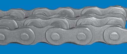
2 TABLE OF CONTENTS ORDERING INFORMATION 3 INSTALLATION 4 LUBRICATION 5 INSPECTIONS 6 ELONGATION LIMITS 7 WHAT IS CHAIN WEAR? Did you know Chain does not STRETCH? Chain Wear is actually when material is removed from Pin and Bushing. TROUBLESHOOTING 8 2 x PITCH WEAR + 2 x PITCH Elongation due to pin and bushing wear INSTRUCTIONS WHEN DISASSEMBLING OR ASSEMBLING CHAINS: WARNING The components of a chain are hardened parts. Striking these parts may cause metal chips to break off from the chain or the tools used resulting in personal injury. During all stages of chain assembly, wear safety glasses to prevent metal parts or chips from entering your eyes and have personnel in the immediate area do likewise. A. Pin Removal 1) If chain is of cotterpin-type construction, remove cotters. 2) If chain is riveted-type construction, grind pin heads off so pin ends are flush with the linkplate. 3) Drive pins out of linkplate using a Diamond pin extractor Model #113 or 135. Some multiple strand chains or large pitch models will require a hammer and punch or a press to remove the pins. B. Installation of Coversides Diamond coversides are manufactured three different ways: (1) Slip Fit, (2) Modified Press Fit, and (3) Full Press Fit. Modified and Full Press Fits require some patience and tools to assemble and/or disassemble. C. Installation of Spring Locks and Cotterpins After coverside have been installed, install spring locks or cotters (depending on chain design). Avoid using bent or worn cotters or spring locks. After spring locks (or cotters) are installed, lightly tap pin ends to position these parts snug against the coverside for additional support. WHEN INSTALLING CHAIN DRIVES ON EQUIPMENT: WARNING You may be seriously injured if you attempt to install chain on equipment under power. Shut off power and lock out gears and sprockets before attempting installation. Once installed, the chain drive must be guarded to prevent personal injury or property damage in the event the chain separates during operation. If chain drive is not guarded, contact equipment manufacturer for recommendations on guarding before using equipment. Knowing more about how the chain is constructed may help in assembly and disassembly. Further information may be obtained by calling or writing Diamond Chain Company: Call toll free: Or write: Diamond Chain Company 402 Kentucky Avenue Indianapolis, IN FAX:
3 ORDERING INFORMATION Basic Information needed to order all chain. Quantity Catalog number Type Riveted or cottered when optional Chain length If you have any questions, please do not hesitate to contact Diamond s sales engineering staff. Headquarters 402 Kentucky Avenue P.O. Box 7045 Indianapolis, IN US CHAIN Service Centers: Dallas, Texas (toll free) (fax) Sacramento, California (toll free) (fax) New Castle, United Kingdom 44-(0) (0) (fax) Brampton, Ontario, Canada (fax) Chain-5 pitches long, roller link each end. Chain-9 pitches long, with bent attachments, both sides of chain, every pitch. Chain-6 pitches long, including connecting link. Chain-9 pitches long, with straight attachments, every pitch. Chain-24 pitches long, riveted endless. Chain-9 pitches long, with all pins extended US CHAIN
4 INSTALLATION To obtain maximum service-life and efficiency from a chain drive, it is necessary that certain precautions in installation be taken. Chain drive installation is relatively simple and good results may be obtained when the following conditions are met: 1. The roller chain, sprockets, and other components are in good condition. 2. The sprockets are properly aligned. 3. Provision is made for adequate lubrication. 4. The chain is correctly tensioned. Condition of Components Shafting, bearings, and foundations should be supported rigidly to maintain the initial alignment. Roller chain should be free of grit and dirt. Wash chain in kerosene when required and then re-lubricate! Drive Alignment Misalignment results in uneven loading across the width of the chain and may cause roller linkplate and sprocket tooth wear. Drive alignment involves two things: parallel shaft alignment and axial sprocket alignment. 1. Shafts should be parallel and level. This condition may be readily checked by the use of a feeler bar, and a machinist s level. If there is axial movement of the shaft (as in the case of an electric motor), lock the shaft in the normal running position before aligning the sprockets. sprockets as close to the shaft bearing as possible. For long center distances, use a taut cord, or wire long enough to extend beyond each of the sprockets. The maximum allowable amount of axial misalignment is obtained from the following formula: Max. Offset = P in or mm Where: P - chain pitch, in inches or mm. This formula applies to both single and multiple strand chains. Installing the Chain Recheck all preceding adjustments for alignment and make certain all setscrews, bolts and nut are tight. Fit chain around both sprockets and bring the free ends together on one sprocket for connection. The sprocket teeth will locate the chain end links. Install the connecting link, and connecting link coverplate, and the spring clip or cotter pins. On larger pitch or heavy multiple strand chains, it may be necessary to lock the sprockets for this operation. When press fit coverplates are used, be careful not to drive the plate on so far as to grip the roller links. Stiff joints can result if this is done. On drives with long spans, it may be necessary to support the chain with a plank or bar as the connection is made. Chain Tension Check chain tension to be certain the slack span has 4-6% mid-span movement in horizontal drives and 2-3% in vertical drives. Please reference the table below. Most single strand drives will perform acceptably if the shafts are parallel and in the same plane within.050 in/ft (4.2 mm/m) or 1/4. However, high speed, high horse power, or multiple strand drives should be aligned within the tolerance obtained from the following formula: Tolerance = C (in/ft), or.111 C (mm/m) P n P n Where: C = center distance, in inches or mm. P = chain pitch, in inches or mm. n = number of chain strands. 2. Sprocket axial alignment can be checked with a straight edge which will extend across the finished sides of the two sprockets. Normally, it is good practice to align the Recommended Possible Mid-Span Movement AC Drive Center-Line Tangent Length Between Sprockets Horizontal to Vertical to AC = Total Possible Mid-Span Movement 4
5 LUBRICATION Roller chain consists of a series of connecting traveling metallic bearings, which must be properly lubricated to obtain the maximum service life of the chain. Although many slow speed drives operate successfully with little or no lubrication beyond the initial factory lubrication, proper lubrication will greatly extend the useful life of every chain drive. The chain drive requires lubrication for six purposes. 1. To resist wear of the pin-bushing joint. 2. To cushion impact loads. 3. To dissipate any heat generated. 4. To flush away foreign materials. 5. To lubricate chain-sprocket contact surfaces. 6. To retard rust or corrosion. A good grade of clean petroleum oil without additives, free flowing at the prevailing temperatures, should be used. Some additives leave a varnish or gum deposit which prevents the oil from entering chain joints. Heavy oils and greases are generally too stiff to enter the chain joints and should not be used. With proper lubrication, a separating wedge of lubrication is formed between the pins and bushings in the chain joints much like that formed in journal bearings. The viscosity of the lubricant greatly affects its film strength, and its ability to separate moving parts. The highest viscosity oil which will flow between the chain linkplates and fill the pin-bushing areas will provide the best wear life. This is essential to minimize metal to metal contact and, if supplied in sufficient volume, the lubricant also provides effective cooling and impact dampening at higher speeds. Note: Speeds beyond the maximum recommended for chain operation are indicated in the horsepower rating tables with zero horsepower. Operation at these or higher speeds will result in excessive galling of the chain pins and bushings regardless of the volume of oil applied. Chain drives should be protected from abrasive and corrosive conditions, and the oil supply kept free of contamination. Periodic oil changes are desirable. only cannot reach pin-bushing joints, and therefore, cannot retard chain elongation due to wear. The lengthening of chains in service results from wear on pin and bushing surfaces, not rollers. When lubricating multiple strand chain, it is important that lubricant be directed to each row of chain linkplates. In conveyor applications, oil should be directed between the rollers and bushings as well as between the chain linkplates. The following table indicates the lubricant viscosity recommended for various surrounding temperatures: Recommended Grade Temperature, F SAE 5-50 to + 50 SAE to + 80 SAE to SAE to SAE to SAE to There are three basic types of lubrication for roller chain drives. Close adherence to the recommended type of lubrication is essential to obtaining maximum service life of a chain drive. The recommended type of lubrication as shown in the horsepower rating tables is determined by the chain speed and the amount of power transmitted. Manual or drip lubrication. (Type A) Oil should be applied periodically between the chain linkplate edges with a brush, spout can, or drip lubrication. Wick Packed Distributing Pipe Sight Feed Lubricator Chain Cross-Section Showing Exaggerated Clearances Note: Oil should be applied to the lower span of chain on the upper edges of linkplates since access of oil to pin-bushing joints is possible only through the clearances between the roller chain linkplates. Oil applied to rollers Oil bath or oil slinger. (Type B) With bath lubrication, the lower strand of chain runs through a sump of oil in the drive housing. The oil level should reach the pitch line of the chain at its lowest point while operating. Only a short length of chain should run through the oil. A typical drive arrangement for bath lubrication is shown in the illustration below US CHAIN
6 LUBRICATION Oil bath or oil slinger. (Type B) continued Drive arrangements which permit long length of chain to travel through the oil should be avoided as overheating or foaming may result. With slinger disc lubrication, the chain operates OIL LEVEL above the oil level. The disc picks up oil from the sump and deposits it into the chain, usually by means of a trough. The diameter of the disc should produce rim speeds between 600 Ft/Min. minimum and 8000 Ft/Min. maximum. A collector plate is usually required to direct the oil to the chain linkplates. See typical drive installation using slinger disc lubrication immediately below. Oil Stream Lubrication. (Type C) This type of lubrication is required for large horsepower, high speed drives. An oil pump should be provided to spray the oil across the lower span of chain in a continuous stream. Orifices should be placed so that oil is sprayed across each strand of the chain. This type of lubrication may be used up to the maximum speeds shown in the horsepower rating tables for each size of chain, except where the rating is zero. Limiting Chain Speed for Various Types of Lubrication (Chain Speed in Ft//Min.) Chain No Type A Type B Type C Use for speeds higher than Type B limits. All chain drives should receive regular maintenance. Each drive should be inspected after the initial 100 hours of operation. Thereafter, most drives may be inspected at 500 hour intervals. However, drives subjected to shock loads or severe operating conditions should be inspected at 200 hour intervals. At each inspection, the following items should be checked and corrected, if necessary. 1. Check lubrication On slow speed drives, where manual lubrication is used, be sure the lubrication schedule is being followed. If the chain is covered with dirt and debris, clean the chain with kerosene and re-lubricate it. 6 WARNING! NEVER USE GASOLINE OR OTHER FLAMMABLE SOLVENTS TO CLEAN A CHAIN. A FIRE MAY RESULT. IF drip lubrication is used, check for adequate oil flow and proper application to the chain. With bath or pump INSPECTIONS lubrication, check oil level and add oil if needed. Check oil for contamination and change oil if needed. Change oil after the first 100 hours of operation and each 500 hours thereafter. If pump lubrication is used, check each orifice to be sure it is clear and is directing oil onto the chain properly. 2. Check Chain Tension Check chain tension and adjust as needed to maintain the proper sag in the slack span. If elongation exceeds the available adjustment, remove two pitches and reconnect the chain. 3. Check Chain Wear Measure the chain wear elongation and if elongation exceeds functional limits or is greater than 3% (.36 inches in one foot) replace the entire chain. Do not connect a new section of chain to a worn chain because it may run rough and damage the drive. Do not continue to run a chain worn beyond 3% elongation because the chain will not engage the sprockets properly and it may damage the sprockets.
7 INSPECTIONS 4. Check Sprocket Tooth Wear Check for roughness or binding when the chain engages or disengages from the sprocket. Inspect the sprocket teeth for reduced tooth section and hooked tooth tips. If these conditions are present, the sprocket teeth are excessively worn and the sprocket should be replaced. Do not run new chain on worn sprockets as it will cause the new chain to wear rapidly. Conversely, do not run a worn chain on new sprockets as it will cause the new sprockets to wear rapidly. 5. Check Sprocket Alignment If there is noticeable wear on the inside surface of the chain roller linkplates, the sprockets may be misaligned. Realign the sprockets as outlined in the installation instructions to prevent further ab normal chain and sprocket wear. 6. Check for Drive Interference Check for interference between the drive and other parts of the equipment. If there is any, correct it immediately. Interference can cause abnormal and potentially destructive wear on the chain or the interferring part. If the edges of the chain linkplates impact against a rigid part, linkplate fatigue and chain failure can result. Check for and eliminate any buildup of debris or foreign material between the chain and sprockets. A RELATIVELY SMALL AMOUNT OF DEBRIS IN THE SPROCKET ROLL SEAT CAN CAUSE TENSILE LOADS GREAT ENOUGH TO BREAK THE CHAIN IF FORCED THROUGH THE DRIVE. 7. Check for Failure Inspect the chain for cracked, broken or deformed parts. If any of these conditions are found, REPLACE THE ENTIRE CHAIN, even though portions of the chain appear to be in good condition. In all likelihood, the entire chain has been damaged. For additional technical assistance, contact any of Diamond Chain s Distribution Centers, United States sales offices or stocking distributors located throughout the world. Our engineers will assist with any customchain application or installation. At Diamond Chain Company, we believe service is as important as quality. Measuring Length FOR REFERENCE ONLY 3.0% Max. Elongation Adjustable Center Distance Drives 1.5% Max. Elongation Fixed Center Distance Drives Chain Wear Scale available free from any Diamond Sales Representative. Chain Pitch ANSI Chain No. Chain Wear Elongation Limits Measured Length Pitches Nominal At 3% Wear in. mm in. mm in. mm US CHAIN
8 TROUBLESHOOTING GUIDE EXAMPLES Pin Galling Interference Pin Tensile Failure Roller Link Plate Tensile Failure Tooth Topping and Roller Damage 8
9 TROUBLESHOOTING GUIDE EXAMPLES Pin Fatigue Failure Pin Link Plate Fatigue Failure Roller Link Plate Fatigue Failure Offset Link Plate Fatigue Failure Sprocket Wear US CHAIN
10 TROUBLESHOOTING GUIDE CONDITION/SYMPTOM POSSIBLE CAUSE WHAT TO DO Tight Joints Dirt or foreign material in chain joints. Clean and re-lubricate chain. Inadequate lubrication. Misalignment. Internal corrosion or rust. Overload bends pins or spreads roller linkplates. Replace chain. Re-establish proper lubrication. Replace sprockets and chain if needed. Realign sprockets. Replace chain. Eliminate cause of corrosion or protect chain. Replace chain. Eliminate cause of overload. Rusted Chain Exposed to moisture. Replace chain. Protect from moisture. Water in lubricant. Change lubricant. Protect lubrication system from water. Replace chain. Inadequate lubrication. Provide or re-establish proper lubrication. Replace chain, if needed. Turned Pins Overload. Replace chain. Eliminate cause of overload. Inadequate lubrication Replace chain. Re-establish proper lubrication. Enlarged Holes Overload. Replace chain. Eliminate cause of overload. Broken Pins Broken Linkplates Extreme Overload. Replace chain. Replace sprockets if indicated. Eliminate cause of overload or redesign drive for larger pitch chain. Missing Parts Missing at assembly. Replace chain. Broken, Cracked or Deformed Rollers Broken and lost. Speed too high. Sprockets too small. Chain riding too high on sprocket teeth. Find and correct cause of damage. Replace chain. Replace chain. Reduce speed. Replace chain. Use larger sprockets, or possibly redesign drive for smaller pitch chain. Replace chain. Re-tension chain more often. Pin Galling Speed or load too high. Reduce speed or load. Possibly redesign drive for smaller pitch chain. Inadequate lubrication. Provide or re-establish proper lubrication. Chain Climbs Sprocket Teeth Excess chain slack. Re-tension chain. Excessive chain wear. Replace and re-tension chain. Excessive sprocket wear. Replace sprockets and chain. Excessive overload. Replace chain. Eliminate cause of overload. 10
11 TROUBLESHOOTING GUIDE CONDITION/SYMPTOM POSSIBLE CAUSE WHAT TO DO Missing or Broken Cotters Cotters installed improperly. Install new cotters per manufacturer s instructions. Exposed Chain Surfaces Corroded or Pitted Cracked Linkplates (Stress Corrosion) Vibration. Excessively high speed. Exposure to corrosive environment. Exposure to corrosive environment combined with stress from press fits. Replace chain. Reduce vibration. Use larger sprockets. Replace chain. Reduce speed. Redesign drive for smaller pitch chain. Replace chain. Protect from hostile environment. Replace chain. Protect from hostile environment. Cracked Linkplates (Fatigue) Loading greater than chain s dynamic capacity. Replace chain. Reduce dynamic loading or redesign drive for larger chain. Battered Linkplate Edges Chain striking an obstruction. Replace chain. Eliminate interference. Worn Linkplate Contours H Chain rubbing on casing, guide, or obstruction. Replace chain if 5% or more of height worn away. Retension chain. Eliminate interference. 5% of H Excessive Noise Chain striking an obstruction. Replace chain. Eliminate interference. Wear on Inside of Roller Linkplates and One Side of Sprockets Loose casing or shaft mounts. Excess chain slack. Excessive sprocket wear. Sprocket misalignment. Inadequate lubrication. Chain pitch too large Too few sprocket teeth. Sprocket misalignment. Tighten fasteners. Re-tension chain. Replace and re-tension chain. Replace chain and sprockets, if needed. Realign sprockets. Replace chain if needed. Re-establish proper lubrication. Redesign drive for smaller pitch chain. Check to see if larger sprockets can be used. If not, redesign drive. Replace sprockets and chain if needed. Realign drive. Re-tension chain. Chain Clings to Sprocket Excessive sprocket wear. Replace sprockets and chain. Sprocket misalignment. Replace sprockets and chain if needed. Realign sprockets US CHAIN


12 CALL US CHAIN FAX Kentucky Avenue Indianapolis, IN
DIAMOND ROLLER CHAIN. For Agricultural and Construction Equipment
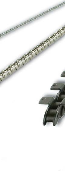
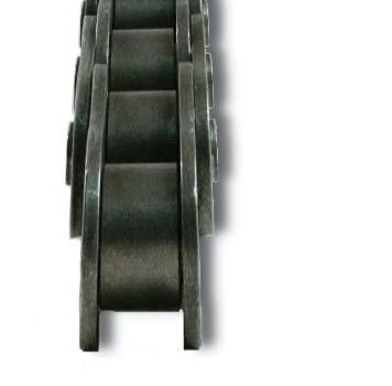
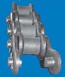
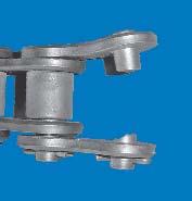
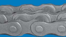
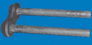
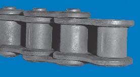
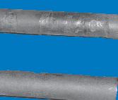
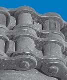
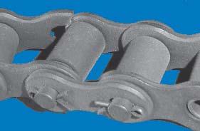
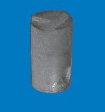
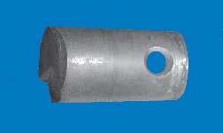
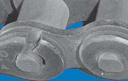
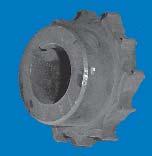
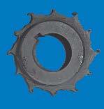
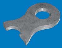
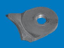
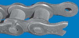
 DIAMOND ROLLER CHAIN For Agricultural and Construction Equipment FABRICATION While roller chain would appear to be a simple product, the number of components in a ten foot section of 40 pitch chain totals
Drivetractors DANGER DANGER DANGER
 Installation Instructions Drivetractors DANGER Lifting Operations Installation of equipment such as s Drivetractors requires performing overhead lifting operations. Proper lifting procedures involve training,
British Standard Chain Product Guide 0508
 British Standard Chain Product Guide 0508 Diamond Chain History 1890 The Indianapolis Chain & Stamping Company began trading as specialist bicycle chain makers. Diamond Chain has a long history of producing
V-Belt Installation, Maintenance & Storage Installation
 V-Belt Installation, Maintenance & Storage Installation 1. Check pulleys for rust, oil, grease, dust, dirt and other foreign materials. Clean the pulleys. Foreign materials accelerate belt wear and dramatically
CAUTION MAINTENANCE INFORMATION CONNECTING AND DISCONNECTING CHAIN
 CONNECTING AND DISCONNECTING CHAIN Introduction Chains are manufactured with connectors, either pins or rivets of various constructions depending upon the chain type, i.e., offset or straight sidebar,
Instruction and Installation Manual
 Instruction and Installation Manual ROSTA Tensioner Devices Tensioners Accessories -G -W -R Sprocket wheel N Chain rider P Oil resistant Up to + 120 C Reinforced Sprocket wheel set Chain rider set -I -F
Timing Belt Installation
 Timing Belt Installation The following is an installation guideline designed to combat problems resulting from improper installation of timing belt drives. 1) Loosen Motor. Check to make sure that the
Provided by: Operating, Maintenance & Parts Manual
 Provided by: www.hoistsdirect.com TB681.qxd 11/29/2004 3:04 PM Page 1 Operating, Maintenance & Parts Manual TB603 Manually Lever Operated Chain Hoist 1100 POUNDS MAXIMUM CAPACITY (500 kg) Follow all instructions
Synchronous Belt Failure Analysis Guide
 Synchronous Belt Failure Analysis Guide Contents Part 1: Common Causes of Belt Failure Normal Belt Wear and Failure Belt Crimp Failures Shock Load Part 2: Improper Belt Installation Tension Introduction
Randy Recommends... If your bike has chain drive, here are some things you should know.
 Chains part 1: Sizing Motorcycle drive chains are made up of alternating internal links and external links, connected by pins. The internal links consist of two plates connected to each other through two
Every Calling is Great, When Great ly Pursued.
 Diamond Motorcycle Oil Field PRoduct and ATV Guide Every Calling is Great, When Great ly Pursued. OLIVER WENDELL HOLMES At the Diamond Chain Company, the calling to design and manufacture the world s highest-performing
REASONS YOUR BEARINGS WILL FAIL. Ritbearing CORPORATION
 12 REASONS YOUR BEARINGS WILL FAIL Ritbearing Things break. No matter what you do, there is always a chance that products you own will fail. The same holds true for bearings, but that doesn t mean that
SAPPHIRE ROLLER CHAIN. Performance that s priced right US CHAIN ( ) diamondchain.com
 diamondchain.com") SAPPHIE OLLE HAIN Performance that s priced right. 1-317-638-6431 1-800 US HAIN (872-4246) diamondchain.com TABLE OF ONTENTS THE NEW STANDAD 3 STANDAD/HEAVY SEIES HAIN Standard Series hain 4 Heavy Series
SAPPHIE OLLE HAIN Performance that s priced right. 1-317-638-6431 1-800 US HAIN (872-4246) diamondchain.com TABLE OF ONTENTS THE NEW STANDAD 3 STANDAD/HEAVY SEIES HAIN Standard Series hain 4 Heavy Series
OIL CAPACITIES FOR SERIES HP APPROXIMATE CAPACITIES IN QUARTS AND GALLONS
 OIL CAPACITIES FOR SERIES HP APPROXIMATE CAPACITIES IN QUARTS AND GALLONS SINGLE REDUCTION REDUCERS - FLOOR MOUNTED POSITION UNIT SIZE 0 5 0 5 0 50 60 80 00 0 WORM OVER GEAR WORM UNDER GEAR VERTICAL OUTPUT
Jet Fans. Instruction Manual READ AND SAVE THESE INSTRUCTIONS WARRANTY
 Jet Fans Instruction Manual READ AND SAVE THESE INSTRUCTIONS WARRANTY All Leader Fan products are guaranteed to be free from defects of workmanship or material and to function satisfactorily when properly
Roller chain catalogue
 Roller chain catalogue www.renold.com Table of Contents Section 1 - BS and ANSI products and dimensions Precision roller chain / chain types... 5 Chain branding... 6 Renold Synergy brand... 7 European
Mechanical Actuators
 Mechanical Actuators Translating Machine Screw Actuators 100-Ton, 150-Ton & 250-Ton Capacity Installation, Operation & Maintenance Instructions Publication Part No. SK-2389-100 CAUTION This manual contains
WARNING DO NOT USE THE PRODUCTS IN THIS GUIDE IN AIRCRAFT APPLICATIONS. THE PRODUCTS IN THIS GUIDE ARE NOT INTENDED FOR USE IN AIRCRAFT APPLICATIONS.
 P O W E R T R A N S M I S S I O N P R O D U C T S power transmission belt drive system Installation, Maintenance and Troubleshooting Guide WARNING DO NOT USE THE PRODUCTS IN THIS GUIDE IN AIRCRAFT APPLICATIONS.
Power Transmission Belt Drive System Installation, Maintenance and Troubleshooting Guide
 Power Transmission Drive System Installation, Maintenance and Troubleshooting Guide www.contitech.us Table of Contents Installation Guide 2 Table of Contents Installation V-s V-s 3 Banded s Torque Team
OPERATOR MANUAL Combo Belt Conveyor
 1 OPERATOR MANUAL Combo Belt Conveyor Document No. 11-01, Rev., 0816 2 WARNINGS THIS CONVEYOR IS DESIGNED FOR A SPECIFIC APPLICATION. CHECK FRAME AND METAL BELT FOR DAMAGE DURING SHIPMENT. READ THE MANUAL
INSTALLATION, OPERATION, AND MAINTENANCE MANUAL RBK FRP FAN
 Bulletin 62-January-20-09 ROOF UPBLAST & SIDEWALL CENTRIFUGAL FIBERGLASS EXHAUST FAN INSTALLATION, OPERATION, AND MAINTENANCE MANUAL RBK FRP FAN The M.K. Plastics catalog on the above corrosion resistant
tRIPr Chief Grain Cart. Operator s Manual. Operator s Manual
 125-000-01 125-000-01 1tRIPr 1tRIPr Operator s Manual 1210 Chief Grain Cart Operator s Manual Operator s Manual TO THE DEALER Predelivery/Delivery Checklist 1210 Grain Cart PREDELIVERY/DELIVERY CHECKLIST
Chain Installation and Maintenance
 The following precautions must be taken before disconnecting and removing a chain from a system prior to replacement. Always shut off power switch to isolate equipment before installing, removing, lubricating,
42in GT Classic Single Stage Snowthrower Conversion Kit XT Series Garden Tractor
 Form No. 9 66 in GT Classic Single Stage Snowthrower Conversion Kit XT Series Garden Tractor Part No. 06 88 Installation Instructions English (EN) This kit is for installing an existing 00 Series Classic
INSTALLATION, OPERATION AND MAINTENANCE MANUAL WALL EXHAUST FANS BELT DRIVE XBL FANS
 INSTALLATION, OPERATION AND MAINTENANCE MANUAL WALL EXHAUST FANS BELT DRIVE XBL FANS The purpose of this manual is to aid in the proper installation and operation of the fans. These instructions are intended
OPERATION SERVICE PARTS TUGIT2. Manually Operated Short Handle Lever Hoist A3140-XXX
 OPERATION SERVICE PARTS TUGIT2 Manually Operated Short Handle Lever Hoist A3140-XXX Sold & Serviced by Morgan Aero 1450 80 th Street SW Everett WA U.S.A. 425/438.9600 SAFETY PRECAUTIONS WARNING! Improper
Chain guide. Chain guide
 Regular maintenance and lubrication are preconditions for low wear and long service life of the chain drive. The maintenance and lubrication frequency, as well as the related re-lubrication, are determined
Lincoln Hoist. Web Hoist Operating Manual. Lincoln Hoist
 Lincoln Hoist Web Hoist Operating Manual Lincoln Hoist Mfg. by Lincoln Precision Machining Company 121 Creeper Hill Road, P.O. Box 458, North Grafton, MA 01536 USA Toll Free (888) 306-7222 Phone (774)
INSTALLATION, OPERATION AND MAINTENANCE MANUAL WALL EXHAUST FANS BELT & DIRECT DRIVE XB, HV, HVA, ADD, DDS, DDP
 INSTALLATION, OPERATION AND MAINTENANCE MANUAL WALL EXHAUST FANS BELT & DIRECT DRIVE XB, HV, HVA, ADD, DDS, DDP The purpose of this manual is to aid in the proper installation and operation of the fans.
V-Belt and Timing Belt Installation and Maintenance
 V-Belt and Timing Belt Installation and Maintenance Introduction The purpose of this manual is simple: to help you get maximum value from your belt drives. As you review this information, you ll understand
PACKING, HANDLING, TRANSPORTING AND STORING MOTORS
 PACKING, HANDLING, TRANSPORTING AND STORING MOTORS Make sure that the shaft of the motor is not loaded in any way and is protected from knocks. Axial loads or shocks may easily damage the bearings inside
NECO Pumping Systems
 INSTALLATION OPERATION & MAINTENANCE INSTRUCTIONS For Your NECO Pumping Systems Fuel Oil Transfer System THIS COMPLETELY ASSEMBLED, TESTED, PACKAGED SYSTEM IS OF THE HIGHEST QUALITY AND DESIGN. TO OBTAIN
Introduction. Lubrication Related Failures. Gear Couplings. Failure Analysis All Types (Page 1 of 7)
") All Types (Page 1 of 7) Introduction A gear coupling serves as a mechanical device which connects shafts of two separate machines and accommodates small amounts of shaft misalignment. Commercial gear couplings
All Types (Page 1 of 7) Introduction A gear coupling serves as a mechanical device which connects shafts of two separate machines and accommodates small amounts of shaft misalignment. Commercial gear couplings
LINDGREN-PITMAN General Maintenance of Lindgren-Pitman Hydraulic Systems & Equipment
 LINDGREN-PITMAN General Maintenance of Lindgren-Pitman Hydraulic Systems & Equipment Page 1 Lindgren Pitman hydraulic driven equipment is designed to give long reliable service with a minimum of repairs
AUTOTORQ HYDRAULIC CHAIN PIPE WRENCH OPERATION MANUAL
 AUTOTORQ HYDRAULIC CHAIN PIPE WRENCH OPERATION MANUAL Page 1 of 19 Table of Contents INTRODUCTION... 2 SAFETY PRECAUTIONS... 3 INSPECTION... 4 SETUP... 4 Step 1: Install the Reaction Unit... 5 Step 2:
Wheel Horse. 44 Snowthrower. for 5xi Lawn and Garden Tractors. Model No & Up. Operator s Manual
 FORM NO. 8 Rev A Wheel Horse Snowthrower for 5xi Lawn and Garden Tractors Model No. 7966 890050 & Up Operator s Manual IMPORTANT: Read this manual, and your tractor manual, carefully. They contain information
Module 6: Air Foundation Brakes
 Air Brakes Terms and Definitions Basic Components That Make Up Air Foundation Brakes Types of Air Foundation Brakes Parts of a Cam Foundation Brake Parts of a Wedge Foundation Brake Parts of a Disc Foundation
SKF Flex Coupling Installation Instructions
 SKF Flex Coupling Installation Instructions The performance of the coupling depends largely upon how you install and maintain. 1. Thoroughly clean all components, paying particular attention to the removal
GROUNDSMASTER. 52 Recycler. for 120 Traction Unit. Model No & UP. Operator s Manual
 FORM NO. 8-980 Rev A GROUNDSMASTER 5 Recycler for 0 Traction Unit Model No. 077 79000 & UP Operator s Manual IMPORTANT: Read this manual carefully. It contains information about your safety and the safety
Aerowerks Toll Free :
 Toll Free : 888-774-1616 Fax : (905)-363-6998 URL: www.aero-werks.com 1 Aerowerks 2018 TABLE OF CONTENTS 1. OPERATION 3 1. START AND STOP INSTRUCTIONS 3 2. PREVENTIVE MAINTENANCE 4-6 2. PREVENTIVE MAINTENANCE
CALIFORNIA TRIMMER MOWER MAINTENANCE MANUAL
 CALIFORNIA TRIMMER MOWER MAINTENANCE MANUAL 2 Table of Contents Section 1: General Information Page Handle Assembly Instructions 4 Maintenance All Models 6 Oil Change Procedures All Models 9 Height Adjustment
Marine Engineering Exam Resource Review of Couplings
 1. What are rigid couplings used for? Used to join drive shafts together. True alignment and rigidity are required. Example Drive shafts and production lines, bridge cranes, solid shaft that needs to be
6722 Rev. A CAPACITY: 22 TON TRUCK AXLE JACK WITH AIR RETURN
 CONTENTS: Page Specifications 2 Warning Information Setup Instructions and Operating Instructions 4 Preventative Maintenance, Inspection and Proper Storage 5 Troubleshooting, Owner/User Responsibility
2013 RT / 2014RT / 2015 RT - Shock Spring Adjuster Installation Instructions
 2013 RT / 2014RT / 2015 RT - Shock Spring Adjuster Installation Instructions Billet Aluminum Adjusters (2) Shock Spring Compressors (Optional) Spanner Wrench (1) BajaRon Decals Not Shown (4) Adjuster Scuff
OPERATION SERVICE PARTS Manually Operated Lever Hoist
 OPERATION SERVICE PARTS Manually Operated Lever Hoist With 21 Handle A3134-XXX A3191-XXX A3192-XXX MA8196-XXX (with special attachments) MA8206-XXX (with special attachments) A3195-XXX MA8195-XXX (with
Maintenance Information
 (Dwg. MHP1539) 16600470 Edition 1 May 2007 Z Rail Aluminum and Steel Overhead Rail System Maintenance Information Save these Instructions The minimum maintenance required for a rail system requires inspection
OPERATIONS MANUAL LEVER CHAIN HOIST
 OPERATIONS MANUAL LEVER CHAIN HOIST IMPORTANT SAFETY INFORMATION Please read, understand and follow all safety information contained in these instructions prior to the use of this hoist. Retain these instructions
42in GT Classic Single Stage Snowthrower Conversion Kit XT Series Garden Tractor
 Form No. 5 70 in GT Classic Single Stage Snowthrower Conversion Kit XT Series Garden Tractor Part No. 06 858 Installation Instructions Original Instructions (EN) This kit is for installing an existing
 AUTOGARD SERIES 820 TORQUE LIMITER Installation and Maintenance Manual DB0009 Issue 11 21 Feb 2017 British Autogard Ltd 2 Wilkinson Rd., Love Lane Industrial Estate, Cirencester, Glos., GL7 1YT UK Tel.
SERIES PC INSTRUCTION AND OPERATION MANUAL
 MEGGA SERIES PC INSTRUCTION AND OPERATION MANUAL Models PCT and PCF Close-coupled and frame-mounted single-stage horizontal end-suction pumps. WARNING: Read this manual before installing or operating this
MAINTENANCE - LPX PORTABLE TREATER
 MAINTENANCE - LPX PORTABLE TREATER Proper maintenance of the Portable LPV Treater is critical for peak performance, reliability and accuracy of this system. The following is a guideline for the type of
SAI GM Series Piston Hydraulic Motor Crankshaft Design Radial Piston Motors
 SAI GM Series Piston Hydraulic Motor Crankshaft Design Radial Piston Motors www.chinawinches.cn (Dimension: inch) Brief Performance Table of Sai GM Series Piston Hydraulic Motor (Full range GM05- GM9 series)
440/880LB ELECTRIC HOIST STF-4488EH
 ELECTRIC HOIST 440/880LB WARNING: Read carefully and understand all ASSEMBLY AND OPERATION INSTRUCTIONS before operating. Failure to follow the safety rules and other basic safety precautions may result
IMPORTANT: If you are experiencing slider issues, it may be due to a period of inactivity and an accumulation of debris in the mechanism.
 IMPORTANT: If you are experiencing slider issues, it may be due to a period of inactivity and an accumulation of debris in the mechanism. Corrosion of vehicle components due to over exposure to very corrosive
Instruction Manual for HSPA Take-Up Units
 Installation Instruction Manual for HSPA Take-Up Units Warning: To ensure the drive is not unexpectedly started, turn off and lockout the power source before proceeding. Failure to observe these precautions
ProLine. 44 Mower. for 120 Traction Unit. Model No & Up. Operator s Manual
 FORM NO. 9 ProLine Mower for 0 Traction Unit Model No. 05 99000 & Up Operator s Manual IMPORTANT: Read this manual carefully. It contains information about your safety and the safety of others. Also become
Technical Manual. Inspection Record For: Hoist Model No.: Hoist Serial No.: Hoist Inspection and Maintenance Guide
 CPTEN-136 Technical Manual Hoist Inspection and Maintenance Guide Inspection Record For: Hoist Model No.: Hoist Serial No.: WARNING! Failure to follow these inspection procedures can cause personal injury
U.S. TSUBAKI DRIVE CHAINS
 DRIVE CHAINS Contents Page ANSI RS ROLLER CHAIN A- ~ A-4 INTRODUCTION A- ~ A-5 RS5 THROUGH RS4 A-6 ~ A-9 HEAVY SERIES A- RS DOUBLE PITCH ROLLER CHAINS A- SELECTION AND ENGINEERING INFORMATION A- ~ A-4
GatesFacts Technical Information Library Gates Compass Power Transmission CD-ROM version 1.2 The Gates Rubber Company Denver, Colorado USA
 Gary L. Miller Plant Engineering November 7, 1991 DIFFERENCES IN SYNCHRONOUS BELTS All toothed belts are not the same; subtle differences in tooth profiles and construction affect performance. Synchronous
Chapter 11 Rolling Contact Bearings
 Chapter 11 Rolling Contact Bearings 1 2 Chapter Outline Bearing Types Bearing Life Bearing Load Life at Rated Reliability Bearing Survival: Reliability versus Life Relating Load, Life, and Reliability
2 TON CAPACITY PROFESSIONAL SERIES ALUMINUM JACK OWNER'S MANUAL SPECIFICATIONS
 80006 OWNER'S MANUAL CONTENTS: Page 1 Specifications 2 Warning Information 3 Setup, Operating and Preventative Maintenance 4 Troubleshooting 5 Maintenance 6 Exploded View Drawing and Replacement Parts
Specifications For MEYER UTG GEAR STAINLESS STEEL. General: Comply Exception
 MEYER UTG GEAR STAINLESS STEEL General: This under tailgate shall be of the bottom opening design. The entire unit shall rigidly mount to the side of the dump box with single pin quick detachable hardware.
Sofa Slideout Assembly OWNER'S MANUAL. Rev: Page 1 Sofa Slideout Owners Manual
 Sofa Slideout Assembly OWNER'S MANUAL Rev: 06.14.2016 Page 1 Sofa Slideout Owners Manual TABLE OF CONTENTS Warning, Safety, and System Requirement Information 3 Product Information 3 Prior to Operation
Auger Belt Tension Adjustment DB7659
 Rev 1.0 3-23-13 Auger Belt Tension Adjustment DB7659 WARNING Entanglement Hazard - Before performing any adjustment procedures, make sure the engine is off and remove the spark plug wire from the spark
IMPORTANT: If you are experiencing slider issues, it may be due to a period of inactivity and an accumulation of debris in the mechanism.
 IMPORTANT: If you are experiencing slider issues, it may be due to a period of inactivity and an accumulation of debris in the mechanism. Corrosion of vehicle components due to over exposure to very corrosive
PO W ERCO N H A N D LIN G SYST EM S (PT Y) LT D.
 LT D.") POWERCON CR MONORAIL SYSTEM GUIDE About us: POWERCON HANDLING SYSTEMS specialises in complete overhead monorail conveyors as well as complete Turnkey Operation and Factory Automation projects. Established
POWERCON CR MONORAIL SYSTEM GUIDE About us: POWERCON HANDLING SYSTEMS specialises in complete overhead monorail conveyors as well as complete Turnkey Operation and Factory Automation projects. Established
JFETIGER RUNNING MANUAL. Downloaded From JFETC.COM Thu, 20 Sep :15: JFETIGER. * valid at time of download * JANUARY 2015
 JFETIGER-TP-M-001 (REV.3) JFETIGER RUNNING MANUAL JFETIGER JANUARY 2015 JFE STEEL CORPORATION CONTENTS JFETIGER... 1 PREFACE...1 1 PREPARATIONS BEFORE RUNNING...1 1.1 Handle Pipes Carefully...1 1.2 Racking
Type A10. Falk Freedom Disc Couplings Installation and Maintenance. Type A10 Sizes 85 thru 8770 (Page 1 of 5)
") Falk Freedom Disc Couplings Installation and Maintenance Type A0 Sizes 8 thru 8770 (Page of ) How To Use This Manual This manual provides detailed instructions on installation, annual maintenance and parts
Falk Freedom Disc Couplings Installation and Maintenance Type A0 Sizes 8 thru 8770 (Page of ) How To Use This Manual This manual provides detailed instructions on installation, annual maintenance and parts
SERIES G3DB/AG3DB ELEVATOR
 TM INSTRUCTIONS AND PARTS LIST SERIES G3DB/AG3DB ELEVATOR WARNING This manual, and GENERAL INSTRUCTIONS MANUAL, CA-1, should be read thoroughly prior to pump installation, operation or maintenance. SRM00059
BOLT-ON AND WELD-ON FLUSH FLOOR SLIDEOUT SYSTEMS OPERATION AND SERVICE MANUAL
 BOLT-ON AND WELD-ON FLUSH FLOOR SLIDEOUT SYSTEMS OPERATION AND SERVICE MANUAL TABLE OF CONTENTS SYSTEM...... Warning........ Description...... Prior to Operation OPERATION... Main Components... Mechanical...
GatesFacts Technical Information Library Gates Compass Power Transmission CD-ROM version 1.2 The Gates Rubber Company Denver, Colorado USA
 MAKING THE RIGHT SHAFT CONNECTIONS Daniel Schwartz & Gary Porter Power Transmission Design August, 1996 Securing a belt pulley to a drive shaft often seems like such a routine task, that engineers and
What is Wear? Abrasive wear
 What is Wear? Written by: Steffen D. Nyman, Education Coordinator, C.C.JENSEN A/S It is generally recognized that contamination of lubricating and hydraulic oils are the primary cause of wear and component
Standard Series Chain 4-5. Heavy Series Chain 6. Non-Standard Series Chain 7. High Strength/Lift Chain 8-9. Specialty Lubrication DURALUBE Chain 10
 Diamond Oil Field ondensed Poduct Product Guide Guide Table of ontents Standard Series hain 4-5 Heavy Series hain 6 Non-Standard Series hain 7 High Strength/Lift hain 8-9 Specialty Lubrication DUALUBE
MAINTENANCE TECHNIQUES and GEAR UNIT FAILURE MODES. MIKE FIELD DAVID BROWN GEAR INDUSTRIES Revision 1
 MAINTENANCE TECHNIQUES and GEAR UNIT FAILURE MODES MIKE FIELD DAVID BROWN GEAR INDUSTRIES Revision 1 Maintenance Regular maintenance saves money One hour per week of effort can save millions in lost production
Model 320 / 320A Hinge Assembly
 MANUFACTURING CO. THE FIRST NAME IN QUALITY COUPLINGS Installation, Inspection, Operation & Maintenance Guide Model 320 / 320A Hinge Assembly IMPORTANT Read these instructions completely before installing,
INSTALLATION, OPERATION AND MAINTENANCE INSTRUCTIONS
 INSTALLATION, OPERATION AND MAINTENANCE INSTRUCTIONS Contents Section 1. General Observations... 2 2. Operation... 4 3. Control During Operation... 5 4. Trouble Shooting... 6 5. Maintenance... 7 Please
PO Box 645, Stockton, Missouri, FAX superiorgearbox.com W D0446-A 4/1/05 1
 W000-7000-D0446-A 4/1/05 1 SAFETY PRECAUTIONS CAUTION Please read this entire document prior to operating the gear drive. Gear drive failure and / or injury to operators may be caused by improper installation,
LUBRICATION, INSTALLATION, OPERATION & MAINTENANCE INSTRUCTIONS FOR STAINLESS STEEL CONE DRIVE SPEED REDUCERS
 LUBRICATION, INSTALLATION, OPERATION & MAINTENANCE INSTRUCTIONS FOR STAINLESS STEEL CONE DRIVE SPEED REDUCERS Cone Drive double-enveloping worm gear speed reducers are used throughout industry to provide
Lineman s Hoist. Operating, Maintenance & Parts Manual. Follow all instructions and warnings for LMST680-2
 Lineman s Hoist LMST0- Operating, Maintenance & Parts Manual Lineman s Hoist Follow all instructions and warnings for inspecting, maintaining and operating this hoist. The use of any hoist presents some
Notice. Overhead Crane Safety and Inspection Requirements. Daily Operator Inspection Reuirements. Daily Operator Inspection Requirements
 Notice Overhead Crane Safety and Inspection Requirements It is the responsibility of the Owner/User to install, inspect, test, maintain, and operate a crane or associated lifting equipment in accordance
 DRUM BRAKE RIMS Periodic inspection of drum brake rims is necessary to determine indications of uneven or excessive wear. In general, brake rim failures other that regular wear are caused by brake linings
Installation and Maintenance Instructions JSE MAEAD Extruder Clutch. World Leader in Modular Torque Limiters
 World Leader in Modular Torque Limiters Installation and Maintenance Instructions JSE.5-0104MAEAD Extruder Clutch 1304 Twin Oaks Street Wichita Falls, Texas 76302 (940) 723-7800 Fax: (940) 723-7888 E-mail:
Maintenance Instructions
 General Note These instructions contain information common to more than one model of Bevel Gear Drive. To simplify reading, similar models have been grouped as follows: GROUP 1 Models 11, 0, 1,, (illustrated),,
PROPELLER SHAFTS 16-1 PROPELLER SHAFTS CONTENTS
 Z PROPELLER SHAFTS 16-1 PROPELLER SHAFTS CONTENTS page GENERAL INFORMATION... 1 PROPELLER SHAFT REPLACEMENT... 7 SERVICE DIAGNOSIS/PROCEDURES... 3 page TORQUE SPECIFICATIONS... 14 UNIVERSAL JOINT REPLACEMENT...
SPLIT MOUNTED HT750/H1000/NT600 INSTALLATION MANUAL
 9/26/16 HIGH TEMP BEARINGS SPLIT MOUNTED HT750/H1000/NT600 INSTALLATION MANUAL www.hightempbearings.com HTB Split Mounted HT750/1000/NT600 Sleeve Bearings Installation HTB Manual REV A REV A Split Mounted
HOIST ARMY TYPE HOIST IMPORTANT
 AA-93 15 SECTION AT/A/15 Service Instructions and Maintenance Manual 18:i!ii il HOIST ARMY TYPE HOIST IMPORTANT Keep for Future Reference SERVICE INSTRUCTIONS AND MAINTENANCE MANUAL 1 METRIC TON CAUTION:
INSTALLATION, OPERATION & MAINTENANCE MANUAL AXIAL UPBLAST FANS RTA, RWTA, RHTA, RB, RD, RTA SH
 INSTALLATION INSTALLATION, OPERATION & MAINTENANCE MANUAL AXIAL UPBLAST FANS RTA, RWTA, RHTA, RB, RD, RTA SH The purpose of this manual is to aid in the proper installation and operation of the fans. These
Convertible - Rated 3 4-Ton /2-Ton Nylon Strap Hoists Refer to any questions about the use, application, repair or testing of this hoist to:
 Operating and Servicing Instructions for Convertible - Rated 3 4-Ton - 1 1 /2-Ton Nylon Strap Hoists Refer to any questions about the use, application, repair or testing of this hoist to: Hubbell / Chance
Installation and Maintenance Instructions Falk Wrapflex (Page 1 of 7) 1. General Information. 2. Safety and Advice Hints DANGER! Type 10R.
 1. General Information. 2. Safety and Advice Hints DANGER! Type 10R.") (Page 1 of 7) This is the Original Document in English Language Type 10R Type 31R Type 35R Figure 1 - Wrapflex coupling range 1. General Information 1.1. Falk Wrapflex Couplings are designed to provide
(Page 1 of 7) This is the Original Document in English Language Type 10R Type 31R Type 35R Figure 1 - Wrapflex coupling range 1. General Information 1.1. Falk Wrapflex Couplings are designed to provide
SPROCKET ENGINEERING DATA
 Engineering SPROCKET ENGINEERING DATA ROLLER CHAIN DIMENSIONS SPROCKET TOOTH DIMENSIONS MAXIMUM HUB RECOMMENDATIONS APPLICATION AND SELECTION HARDENING CHAIN LENGTH CALCULATION SPEED RATIOS SPROCKET DIAMETERS
Safelift Overhead Runway Beams & Rolling Beam Cranes
 Operation & Maintenance Instructions Instructions for Safe Use Safelift Overhead Runway Beams & Rolling Beam Cranes Certification Safelift overhead runway beams and rolling beam cranes are lifting appliances
Instructions for INSTALLATION -- OPERATION -- MAINTENANCE of the SELAS AIR/GAS BLENDER VALVE. (for PROPANE/AIR, BUTANE/AIR AND OTHER BLENDS)
") DESCRIPTION The SELAS Blender Valve is a three-port, adjustable area valve which accurately mixes any two of a wide variety of gases. Air and Gas ports in a movable piston are matched to complimentary
DESCRIPTION The SELAS Blender Valve is a three-port, adjustable area valve which accurately mixes any two of a wide variety of gases. Air and Gas ports in a movable piston are matched to complimentary
Installation and Maintenance Instructions JSE1-0128MAEAD Extruder Clutch. World Leader in Modular Torque Limiters
 World Leader in Modular Torque Limiters Installation and Maintenance Instructions JSE1-0128MAEAD Extruder Clutch 1304 Twin Oaks Street Wichita Falls, Texas 76302 (940) 723-7800 Fax: (940) 723-7888 E-mail:
08/2010 Rev. 4/28/2017 FMDL, MANUAL. FMDL-Series Single & Double Eagle Beak Fork-Mounted Drum Lifters Use and Maintenance Manual
 Vestil Manufacturing Corp. 2999 North Wayne Street, P.O. Box 507, Angola, IN 46703 Telephone: (260) 665-7586 -or- Toll Free (800) 348-0868 Fax: (260) 665-1339 www.vestilmfg.com Email: info@vestil.com FMDL-Series
Troubleshooting Power Transmission Couplings
 Troubleshooting Power Transmission Couplings Introduction Power transmission couplings are used to connect two shafts that turn in the same direction on the same centerline. There are three principle types
SPROCKET ENGINEERING DATA
 Engineering SPROCKET ENGINEERING DATA ROLLER CHAIN DIMENSIONS SPROCKET TOOTH DIMENSIONS MAXIMUM HUB RECOMMENDATIONS APPLICATION AND SELECTION HARDENING CHAIN LENGTH CALCULATION SPEED RATIOS SPROCKET DIAMETERS
MARLEY ENGINEERED PRODUCTS OPERATING INSTRUCTIONS AND PARTS LIST
 MARLEY ENGINEERED PRODUCTS OPERATING INSTRUCTIONS AND PARTS LIST TUBE AXIAL DUCT FANS INDUSTRIAL PROPELLER FANS INDUSTRIAL ROOF EXHAUSTERS HEAVY DUTY MAN/PRODUCT COOLERS WARNING BY ACCEPTANCE OF THIS MERCHANDISE,
Trench Filler for Compact Utility Loaders
 Form No. 3353-608 Rev A Trench Filler for Compact Utility Loaders Model No. 22472 260000001 and Up Operator s Manual Register your product at www.toro.com Original Instructions (EN) Contents Page Introduction................................
CHESTER HOIST AIR LOW HEADROOM CHAIN HOISTS AL-680 SECTION A
 CHESTER HOIST AIR LOW HEADROOM CHAIN HOISTS AL-680 SECTION A OPERATING and MAINTENANCE INSTRUCTIONS FOR AL SERIES HOISTS Users should refer to the ANSI B30.16 American National Standard and ASME HST-5M
7400 Series End Drive Conveyors
 700 Series End Drive Conveyors Installation, Maintenance and Parts Manual Flat Belt Conveyor Cleated Belt Conveyor DORNER MFG. CORP. INSIDE THE USA OUTSIDE THE USA P.O. Box 0 975 Cottonwood Ave. TEL: -800-97-866