OILLESS ROTARY VACUUM PUMP & BLOWER ORION DRY PUMP CAUTION
|
|
|
- Estella Mills
- 5 years ago
- Views:
Transcription


1 INSTRUCTION MANUAL OILLESS ROTARY VACUUM PUMP & BLOWER ORION DRY PUMP KRF70 KRF110 KRF70 CAUTION This product is intended only for industrial use. Use with caution. Read this Instruction Manual and follow the instructions described herein. Please keep this Instruction Manual for future reference. No lubrication! 35
2 Thank you very much for your purchase of the Orion pump. Read this instruction manual in advance to use this pump safely and to ensure continuing good performance. The product mechanism and specifications are subject to change without notice. If mechanism or specifications are changed, contents of this manual may not match the actual product. Safety Information Read "Precautions for Safety" before operation to ensure safe operation. Safety instructions in this manual are intended to ensure safe and correct pump operation and to prevent damage or personal injury. Safety instructions in this manual are classified into Danger, Warning, and Caution. Danger Warning Caution Indicates an imminently hazardous situation that, if the product is misused, may bring about death or serious injury to the operator. Indicates a potentially hazardous situation that, if the product is misused, may bring about death or serious injury to the operator. Indicates a critical situation that, if the product is misused, may bring about injury to the operator or damage to the product. Additionally, the situation that is explained in Caution column may cause serious accident. All safety information must be followed for safe operation. After reading this manual, keep it where an operator can refer to it anytime. When transferring or renting this product, attach this manual to the product where a new owner can easily refer to it for proper operation. Symbols The symbol represents warning or caution. What is shown inside or described near informs of an actual hazard. The example on the left means caution for electric shock. The symbol represents prohibition. What is shown inside or described near informs of an actual action which is prohibited. The example on the left means prohibition of disassembly. The symbol represents essential action or instruction. What is shown inside or described near informs of an actual instruction about operation. The example on the left means disconnect the power plug from the outlet. The symbol represents important information other than warning or caution. Although model KRF70 is used as description pictures and figures in the manual, the other models in the KRF-series are operated the same way as KRF70 if there is no note. Be sure to read through the safety information.
3 Contents Precautions for Safety 2 Precautions for Proper Operation 6 Names of Components 7 Preparation and Confirmation 9 Operation Procedure 13 Maintenance and Inspection 16 Troubleshooting 18 Consumable Parts 20 Storage(Not in Use for a Long Time) 23 Disposal 23 Specifications 24 Dimensional Outline Drawing 26 1

4 Precautions For Safety Precautions for Use (Danger / Warning) Danger Indicates an imminently hazardous situation that, if the product is misused, may bring about death or serious injury to the operator. Keep flammable or explosive gas out. Keep the pump from inhaling flammable or explosive gases. Do not use the unit in the place where flammable or explosive gas exists. It may cause explosion or fire. Warning Indicates a potentially hazardous situation that, if the product is misused, may bring about death or serious injury to the operator. Do not block the exhaust piping. (B type and V B type) Do not operate the pump while the pressure controller is totally closed or the exhaust piping is blocked. Blocking the exhaust air may increase the pressure and temperature in exhaust piping, and result in injury and malfunction due to burst of the piping and pump parts. Do not wash filter element with organic solvents. When cleaning the filter element, do not use organic solvents such as thinner, alcohol, benzine, gasoline, and kerosene. It may result in explosion or fire. Do not remove the cover during operation. Do not operate this product while the main cover is removed. Otherwise, your hand(s) may be cut off or be seriously hurt because the cooling fan and the coupling rotate at high speeds. Prevent the power cord from any damage. Do not damage, bend, pull, or bind the power cord. Do not place heavy object on it or let it get caught or pinched. It may damage the cord, and may cause electric shock or fire. Keep this product away from water. Do not pour water over the pump and the motor, and do not use water for cleaning this product. Also, do not use this product where it may touch water or other liquid. It may cause electric shock or fire. Be alert to electric shock. Do not touch electrical parts such as power plug with wet hands. Also, do not operate switch with wet hands. It may cause electric shock. Never fail to put the terminal box cover on. In the case of a motor with the terminal box, do not operate it with the terminal box cover removed. It may cause electric shock. Do not modify the product. Do not modify the product. It may cause abnormal operation and may result in injury, electric shock or fire. Be sure to ground this product. Be sure to ground the product with the screw for grounding inside the terminal box or at the lower part of the frame of the motor. Failure to do so may cause electric shock. 2
5 Precautions For Safety Precautions for Use (Warning / Caution) Warning Indicates a potentially hazardous situation that, if the product is misused, may bring about death or serious injury to the operator. Installation must be done by specialized personnel. The product may fall down or drop if it is improperly installed. It may result in personal injury, electric shock or fire. Do not operate this product under abnormal conditions. Stop the operation when it is abnormal. Then, pull out the power plug or shut off the main power supply, and consult with our dealer or a specialized company. If the operation is continued under such conditions, it may cause electric shock or fire. Shut off the main power supply before cleaning, maintenance and inspection. Shut off the main power supply before cleaning, maintenance, and inspection, and clearly post a sign on the power supply switch to indicate it is under cleaning, maintenance, and inspection. Failure to do so may result in electric shock or personal injury. Consult with a specialized company for maintenance and inspection. Inspect the power plug periodically. If the product is operated with the power plug, periodically inspect the power plug and confirm it is not covered with dust. The power plug must be fully inserted to the root of pins. If the power plug is covered with dust or not fully inserted, it may cause electric shock or fire. Be sure to install the protective device. Consult with a specialized company to install an earth leakage breaker. Failure to do so may cause electric shock or fire. Also, install an overload protection device (thermal relay). Operation without such a device may cause malfunction due to overload or fire. Contact with a specialized company when the earth leakage breaker is activated. When the earth leakage breaker is activated, contact with a specialized company. If you force to turn on the power supply, it may cause electric shock or fire. Do not use this product outdoors. This product is intended for indoor use. If the product is used outside and is exposed to wind or rain, the motor may suffer from incomplete insulation and may cause electric shock or fire. Caution Indicates a critical situation that, if the product is misused, may bring about injury to the operator or damage to the product. Do not use the machine over the specified pressure. If using the machine over the specified pressure, it may shorten the life of product and may cause failure, abnormal generation of heat or trouble. Prohibition of operation with the vacuum pipe closed (V type and V B type) Do not operate the pump with the vacuum controller closed completely to close the vacuum pipe. Negligence may cause an abnormal pump temperature rise resulting in a product failure, protective cover deformation or burn injury. Do not sit on, lean on, or place objects on this product. Do not place heavy objects or object containing water on the product, and do not get on it. If you get on the product, you may fall and be injured. If water spills, it may cause rust inside or poor insulation and may cause leakage or electric shock. 3
6 Precautions For Safety Precautions for Use (Caution) Caution Indicates a critical situation that, if the product is misused, may bring about injury to the operator or damage to the product. Do not operate this product with any voltage other than the rated one specified for the motor. Operation with any voltage other than the rated voltage specified for the motor may result in failure or accident. Prevention of melting of distribution cable covering due to contact. Install the motor so that wiring cables do not touch the motor frame. Contacting with cables may result in melting covering or ignition. Be alert to burn. Do not touch areas around the dry pump, and the exhaust port and the piping surface of exhaust side. They are heated to high temperature, and it may result in burn. Inspect the earth leakage breaker periodically. Periodically check performance of the earth leakage breaker. If using the product with failure of the earth leakage breaker, it may cause electric shock in case of short circuit. Installation of check valve Residual pressure may reverse the rotation when the pump is stopped. Be sure to install the check valve horizontally within 50cm from the inlet port (or the exhaust port) of pump. No installation of check valve may cause malfunction. Turn off the main power supply in case of not using the pump for a long time. When you do not use the product for a long time, shut off the main power supply. Otherwise, it may cause electric shock or short circuit ignition due to degenerated insulation. Be sure to wear personal protective equipment for cleaning and maintenance. When you carry out cleaning or maintenance, be sure to wear gloves. Failure to do so may result in injury or burn. When you transfer the product, be sure to wear nonslip gloves and safety shoes. Failure to do so may result in injury. Continuous operation is recommended. If the start and stop frequency is high, start and stop cycle in 5 minutes or less, it may cause significant lifetime deterioration or malfunction of the product. Product Use Limitations (1) If the unit is to be used as part of critical installations, safety devices and backup systems which can be switched to should be put into place to insure that serious accidents or losses do not occur in the event that the unit should break down or malfunction. (2) This product was designed and produced as a general purpose device for use in ordinary manufacturing. Accordingly, this warranty does not apply to nor cover the following applications. However, in cases where the customer/user takes full responsibility and confirms the performance of the equipment in advance, and takes necessary safety precautions, please consult with ORION and we will consider if use of the unit in the desired application is appropriate. 1Atomic energy, aviation, aerospace, railway works, shipping, vehicles (cars and trucks), medical applications, transportation applications, and/or any applications where it might have a great effect on human life or property. 2Electricity, gas, or water supply systems, etc. where high levels of reliability and safety are demanded. 4


7 Precautions For Safety Precautions for Use (Caution) Pull out the power plug to disconnect it. When the product is used with power plug, pull the power plug to disconnect it. Pulling the power cord may result in disconnection of part of the core wire, and may cause generation of heat or deterioration. Precautions For Safety Warning Label Position on the Product Warning Label Position on the Product The following warning labels are selected as most important ones out of Safety Information and are placed on the product. Read the labels before operating the product. When the labels become unreadable due to scratch or dirt, contact with your dealer to get new ones for replacement. Electric shock Burn 5
 Prohibition of operation in reverse rotation. Set the ambient temperature of the dry pump to the range of 0 to 40 degrees C.")

8 Precautions for Proper Operation For inlet air, aim at normal temperature and normal humidity clean air with little dust but free from corrosive and explosive gases. Normal temperature: 0 to 40 deg. C Normal humidity: 65% +/- 20% (JIS Z 8703) Prohibition of operation in reverse rotation. Set the ambient temperature of the dry pump to the range of 0 to 40 degrees C. Try not to cause condensation inside the pump. Keep the pump away from oil, water, dust, rain, etc. Also, never lubricate the product. Be sure to use under specified pressure or less. Do not remove the main cover, and top and bottom partition plates. Removing these cover and plates may result in shortening the life of product severely due to the temperature rise. Install the product on a flat surface.. Periodically replace consumable parts (see pages 20) and replacement parts (see page 21). Be sure to Install the product on the level while whole base is touching on the level surface like in figure A. do not Install the product like in figure B. Fig.A Fig.B Cushion rubber etc 6


 Main cover 70 No.")

9 Name of Components KRF70 mark indicates consumable parts that is replaced depending on wear condition when checking. (Refer to page 20.) mark indicates replacement parts that is replaced 1 Compound gauge periodically at the specified period. 2 Vacuum controller VC81 (Refer to page 21.) 3 Pressure controller PCA8 SD case cover Gauge cover 70 VC81 Dry pump deal drawing Hexagon socket head plug VFF-70 MFF70 Partition plate top Eyebolt Supplementary bolt Motor Attachment Gasket (B) Main cover 70 No.1 Processing chart of coupling Spider Fan cover 70 Fan coupling Main cover 70 No.2 Fan Pump Base Pump deal drawing Exploded view of filter body Bearing Retainer Liner Bearing Parallel key Cylinder Cap Suction case Gasket Spring tube Blade Rotor Stay bolt Filter Element Rubber packing Filter Case Packing Knob nut Spacer Bearing Long cap 70 Delivery case Gasket Stay bolt Packing Beari Side Plate(B) Spacer Liner Squeezing tube Rubber packing Muffler case Knob nut 7
 mark indicates replacement parts that is replaced 1 Compound gauge 1 2 3 periodically at the specified period.")
 3 Pressure controller PCA10 Dry pump deal drawing SD case cover Gauge cover 110 MFF110 VFF110 Eyebolt Supplementary bolt VC100B Motor Gasket (A)")
 Exploded view of filter body Delivery")
10 Name of Components KRF110 mark indicates consumable parts that is replaced depending on wear condition when checking. (Refer to page 20.) mark indicates replacement parts that is replaced 1 Compound gauge periodically at the specified period. 2 Vacuum controller VC100B (Refer to page 21.) 3 Pressure controller PCA10 Dry pump deal drawing SD case cover Gauge cover 110 MFF110 VFF110 Eyebolt Supplementary bolt VC100B Motor Gasket (A) Main cover 110 No.1 Fan cover 110 Processing chart of coupling Spider Fan coupling Fan Pump Main cover 110 No.2 Base Liner Bearing Retainer Bearing Pump deal drawing Blade Parallel key Cylinder Long cap 100 Gasket (B) Exploded view of filter body Delivery case Muffler case Gasket (B) Rotor Bearing Retainer Suction case Gasket (B) Cap Spring tube Filter Case (B) Packing Side Plate(B) Liner Bearing Stay bolt Rubber packing Filter Element F Knob nut 8
11 Preparation and Confirmation Before Installation/ Installation Danger Do not use the product where flammable gas or explosive gas may exist. Warning Set up the product where it is protected from water, oil and dust. Please use the product indoors. Do not set up the product where corrosive gas (chlorine or sulfur dioxide gas) exists. Do not set up the product under direct sunlight. Use the product where the ambient temperature ranges 0 to 40 degrees in Celsius. When you transport the product, lift up with slings. Before Installation The product is heavy. Be careful enough when moving the product. Upon receiving the product, check it carefully for signs of shipping-related damage like scratches, deformation, etc. If you notice a problem, contact with your dealer. Be sure to check the name plate whether purchased product is right model as you ordered. When the product is delivered with accessories, be sure to check the accessories whether there are all the parts or not. Name plate Installation When the product is 25kg or over, hold the product with two persons. Also, do not hold the terminal box of motor, filter case, and controller when holding with two persons. Holding the terminal box and filter case of the motor may result in injury, damage or malfunction if product or parts of it are dropped. In case of using a hanging belt, be sure to belt as shown in the photo. Do not hang a sling for these parts. Photo 9
12 Preparation and Confirmation Installation Site/ Gauge & Controller Installation Site Warning Installation should be carried out by your dealer or special service company. Improper installation may result in vibration, electric shock, or fire. Set up the product in a wide space where you can easily maintain, inspect and overhaul the product. Ambient temperature of the pump is 40 deg. C or less. If there is any heat source near the pump, be sure to check the ambient temperature does not exceed 40 deg. C. Using the product in the enclosed space may result in malfunction due to the generation of heat of the pump. Ventilate adequately around the pump, and be careful not to exceed the permissible ambient temperature. Be sure to install the product horizontally while the whole base plate is touching the level surface. Warning Installation of check valve Residual pressure may reverse rotation when the pump is stopped. Be sure to install the check valve within 50cm from the inlet or outlet port of the pump. No installation of check valve may cause malfunction. Gauge & controller KRF70 Be sure to install the gauge according to following procedure. Remove the cover. Install the gauge. Press it back in place until the cover claw is locked. Claw Push the check point, remove the claw and pull the case foward. For the controller installation position, refer to the outer dimension drawing provided on P Do not apply a sealing tape when installing the pressure gauge. (Do not overtighten.) Do not apply a sealing tape on the threads. After tightening the controller hand-tight, give an additional quarter to half turn using a tool. Smooth surface due to application of a sealing tape may result in excessively tightening the controller. This may damage or deform the thread part and cause malfunction. (There is no need of securing high airtightness using a sealing tape or adhesive agent because the pump is designed for low pressure/vacuum.) Compound gauge is a part that is weak against impacts. Do not hit or drop the product with compound gauge. 10
13 Preparation and Confirmation Gauge & Controller / Piping KRF110 Be sure to install the gauge according to following procedure. Remove the cover. Install the gauge. Press it back in place until the cover claw is locked. Claw Push the check point, remove the claw and pull the case foward. For the controller installation position, refer to the outer dimension drawing provided on P Do not apply a sealing tape when installing the pressure gauge. (Do not overtighten.) Do not apply a sealing tape on the threads. After tightening the controller hand-tight, give an additional quarter to half turn using a tool. Smooth surface due to application of a sealing tape may result in excessively tightening the controller. This may damage or deform the thread part and cause malfunction. (There is no need of securing high airtightness using a sealing tape or adhesive agent because the pump is designed for low pressure/vacuum.) Compound gauge is a part that is weak against impacts. Do not hit or drop the product with compound gauge. Piping 1.Avoid direct connection with steel pipe. Use hose for inlet and exhaust piping. In case of direct connection with steel pipe, resonance with the piping system may cause noise or vibration. For exhaust piping, use heat resistant and pressure resistant (100kPa or over) hose. Completely remove dirt and dust inside the hose before piping. 2.When intake air contains a big amount of dust, or if dust grains are very fine (10μm or less), use an appropriate filter in addition to the accessory filter. 3.Install the hose of the exhaust piping system properly in order to prevent condensed water inside the system from entering the pump, and from discharging from the piping end. If condensed water in the piping system enters the pump, the pump inside may be locked by rust or the blades may not come out. To avoid this situation, take the following measures: 1Install the valve or drain in the exhaust piping system so that the condensation of water occurred inside the system can drain out. Also, drain out the collected condensation of water periodically. (See Figure 1.) Provide valve or drain hose on the pump side in order Piping end side Piping end side to prevent condensed water from entering into the pump. In case of a long piping system, provide valve or drain hose in the halfway of the system. When condensed water discharges from the piping end, install a valve or drain hose at the piping end. Drain or valve (Figure 1) 2If the pump is not frequently used, idle the pump for 10 to 15 minutes after finishing operation. 11
14 Preparation and Confirmation Piping / Electrical Wiring 4.If reverse rotation is caused by residual pressure upon stopping the pump, blade damage is likely to be incurred. Please install a check valve within 50 cm from the pump's inlet port (or exhaust port) to prevent this from happening. In installing a check valve, install it levelly to the floor. Negligence may cause pulsation or abnormal noises. (Figure 2) (Recommended check valve: manufacturer's product name: JIS compliant KITZ bronze swing check valve) 5.Do not apply a sealing tape when connecting pipes. Pieces of torn sealing tape may cause controller malfunction or abnormal operation sound. 6.Do not overtighten pipes. Overtightening pipes may damage the SD case. Check valve (Figure 2) Example of check valve installation Electrical Wiring Warning Contact with a specialized company to install an earth leakage breaker. Failure to do so may cause electric shock or fire. Also, install an overload protection device (thermal relay). Failure to do so may cause failure to the product due to overload or fire. 1.Install the earth leakage breaker. Set the breaking capacity to 1.5 times the current value shown on the motor name plate as a rough guiding value. Select a sensed current of 30mA. Consult with a specialized company for electrical installation. 2.Be sure to install the grounding. Location of grounding screws: The grounding is attached on the terminal box. (You can find the mark "E" or mark " " near the screw.) Select a copper wire, with a nominal cross section bigger than the cross section shown in the example, as grounding wire. Motor rated output (kw) Nominal cross section(mm 2 ) When the grounding screw becomes loose due to vibration during operation, sparks will occur at the grounding section. Wire the grounding cable so that the grounding screw does not loose due to vibration during operation, and tighten the screw with locking. 3.Install the overload protection device (e.g. thermal relay). Make the V specification 100%, and B and VB specifications 110% against the rated current value written on the motor name plate for the set value. 4.Operate the pump with the rated power supply written on the motor name plate. 5. A special characteristic of the dry pump is that during initial operation, the rated current value may be exceeded at the start, but will drop over time.(note that depending on the specifications and/or operating conditions, there are cases it may not drop to the rated current value or below.) Consult with your dealer if the overload protector (thermal relay) activates during initial operation or during normal operation. 6.Select a power cord referring to the current value shown on the pump name plate. 7.Be sure to keep the power supply cable with holding assembly in order not to get stressed to the internal power supply connection terminal at the time of pulling the cable. (Recommended holding assembly: Maker; UI Lapp GMBH/ Product name: Skintop/ Model: ST-M, STR-M) 12


.")


15 Preparation and Confirmation Electrical Wiring 7.Motor name plate (V, B, or VB enters into the.) Matsushita-made motor is mounted for three-phase specification. Mitsubishi-made motor is mounted as standard for single-phase specification. KRF , KRF70- H-01 KRF KRF , KRF70- H-04 KRF Check before Operation Operation Procedure Check before Operation/ Operation Install the earth leakage breaker. Consult with a specialized company for electrical installation. Install the overload protection device (e.g. thermal relay). Make the V specification 100%, and B and VB specifications 110% against the rated current value written on the motor name plate for the set value. Before using a machine that has not been used for a long period of time, be sure to check that the power is off, and then rotate the rotor (fan, motor fan etc.) gently to confirm that it can be rotated smoothly. Compound gauge is a part that is weak against impacts. Do not hit or drop a product with compound gauge. When storage temperature and operation temperature are differing more than 10 degrees in Celsius, leave the pump at the operation site for more than 2 hours in order to eliminate the temperature difference before using. If condensation water occurred, and the condensation water enters into the pump, it may result in rust, lock, and vanes might block. 13


16 Operation Procedure Operation Operation 1.Turn the control screw in the direction of (-). 2.Be sure to check by inching that the rotating direction is the same as the one shown on the "rotating direction arrow" when it is viewed from the motor fan side. 3. Turn on the power switch. 4. Use the controller to adjust Rotating direction arrow vacuum level and exhaust pressure. Check: Be sure to check the rotating direction. Adjustment of vacuum level and exhaust pressure Adjustment of vacuum level - vacuum + Adjustment of exhaust pressure - pressure + Control screw Locking nut Control screw Vacuum controller Pressure controller Adjustment of vacuum level (Vacuum controller) 1.Turn the locking nut clockwise to unlock the control screw. 2.Turn the control screw until the desired vacuum level is obtained on the gauge. 3.Turn the locking nut counterclockwise to lock the control screw. Adjustment of exhaust pressure (Pressure controller) 1.Turn the control screw until the desired exhaust pressure is obtained on the gauge. 14
17 Operation Procedure Pressure range during operation / How to Correct Vacuum Level (Gauge Pressure) /Stop Pressure range during operation Use as vacuum pump (V type) Use as blower pump(b type) Use as vacuum pump and blower pump (V, B type) kpa KRF70 110(Standard) KRF70(High-pressure) Continuous operative 60 or lower 80 or lower vacuum Continuous exhaust 60 or lower 70 or lower pressure Continuous operative pressure Total of continuous operative vacuum and continuous exhaust pressure 60 or lower Total of continuous operative vacuum and continuous exhaust pressure 80 or lower 1 Recommended range: The pump operating under 1 atmospheric pressure can exert its optimal performance (life, operation noise, etc.) at a vacuum/pressure within this range. Use the pump within the recommended range unless the higher vacuum/pressure is required. Contact with Orion or Orion dealer for other usage. How to Correct Vacuum Level (Gauge Pressure) Correction formula: A = C +( B) A : Vacuum level at 1 atmosphere kpa B : Atmospheric pressure at vacuum level measuring position C: Reading on compound gauge kpa kpa Ex) When the reading on the compound gauge is 76kPa and the atmospheric pressure is 973hPa (97.3kPa), the vacuum level at 1 atmosphere is calculated as follow:76 + ( ) = 80kPa To read the accurate vacuum level, use a mercury manometer or an equivalent meter based on absolute pressure. Atmospheric pressure conversion formula (hpa kpa) Stop B(kPa)=B(hPa) 10 Shut off the power switch. 15


18 Maintenance and Inspection Cleaning of filter element Warning Turn off the main power supply before cleaning, maintenance and inspection. Turn off the main power supply before cleaning, maintenance and inspection, and clearly post a sign on the power supply switch to indicate it is under maintenance. Failure to do so may result in electric shock or personal injury. Consult with a specialized company for maintenance and inspection. Do not wash filter element with organic solvents. When cleaning the filter element, do not use organic solvents such as thinner, alcohol, benzine, gasoline, and kerosene. It may result in explosion or fire. Caution Be sure to wear protective wear. When you carry out cleaning or maintenance, be sure to wear gloves. Failure to do so may result in injury or burn. When you transfer the product, be sure to wear nonslip gloves and safety shoes. Failure to do so may result in injury. 1. Cleaning of Filter Element and Delivery element When debris deposits on the filter element, remove the filter case and muffler case, and then remove Inspection period the filter element and the delivery element to get rid Once a week of the debris with an air blow. If a fouled filter element cannot be cleaned with air blows, replace it with a new one. Contents Remove dust or dirt Filter case/ Muffler case Spring Tube Rubber Paking Knob Nut Assy Paking Filter Element Delivery element 16
19 Maintenance and Inspection Cleaning of Filter Element 2. Cleaning of Controller (Vacuum controller, pressure controller) If the sheet surface of the controller is very dirty, the function may deteriorate. Disassemble the controller periodically, and remove the dirt of each part. 3. Inspection of Piping Be sure to tighten the knob nut of filter case surely and ckeck that there is no air leakage, clogging, or loosening in the piping. Inspection period Once a month Inspection period Once a month Contents Disassembly cleaning Contents Air leak, clogging, looseness of tightened parts (Vacuum controller) VC81(KRF70) VC100B(KRF110) (Pressure controller) PCA8(KRF70) PCA10(KRF110) Sheet surface Sheet surface Sheet surface Sheet surface 17
20 Troubleshooting Warning Turn off the main power supply before cleaning, maintenance and inspection. Turn off the main power supply before cleaning, maintenance and inspection, and clearly post a sign on the power supply switch to indicate it is under maintenance. Failure to do so may result in electric shock or personal injury. Consult with a specialized company for maintenance and inspection. Caution Be sure to wear protective wear. When you carry out cleaning or maintenance, be sure to wear gloves. Failure to do so may result in injury or burn. When you transfer the product, be sure to wear non-slip gloves and safety shoes. Failure to do so may result in injury. Check abnormal factors. 18
21 Troubleshooting Condition Cause Corrective action Vacuum level does not increase. When an abnormal noise is heard or when the meter shows pulsations. When pump is stopped. Filter element is clogged with dust, and air cannot be taken in. Oil entered into the pump, and the vane cannot come out. Foreign object entered into the pump and the vane cannot come out. Due to rust inside of the pump by intaking water, the vane cannot come out. Due to condensation inside of the pump, the vane cannot come out. Damage to meter Tightening of filter case, piping, air tank are not tightened well, and air leaks. The coupling fixing bolt is loose. Decreased pump rotating speed due to motor malfunction. Damaged vane. Worn vane. An abnormal noise is occurred because the pressure is out of allowable range. Excessive exhaust pressure causes an abnormal noise. The abnormal noise occurs due to misfitting of the coupling. The abnormal noise occurs due to burning of the motor. The abnormal noise occurs because mounting bolts became loose. Damage to meter. Filter element is clogged with dust, and air cannot be taken in. Oil entered into the pump, and the vanes cannot come out. Due to condensation inside of the pump, the vanes cannot come out. The vanes were broken because foreign object(s) entered into the pump. The vanes were broken because foreign object(s) entered into the pump. The rotor was touched because the pressure was out of applicable pressure range. Defective electromechanical system Remove the element and blow off dust from the element with compressed air. If the element becomes dirty, replace it with a new one. Consult with our dealer or service personnel. Replace the meter. Consult with our dealer or service personnel. Return the pressure to the applicable pressure range. Adjust the exhaust resistance to return the exhaust pressure to normal. Consult with our dealer or service personnel. Replace the meter. Remove the element and blow off dust from the element with compressed air. If the element becomes dirty, replace it with a new one. Consult with our dealer or service personnel. 19
22 Consumable parts List of Consumable Parts List of Consumable Parts (Parts to be replaced depending on wear condition when checking.) Name of Parts Model KRF70 KRF110 Parts Number Filter element Quantity /unit 1 (Inlet side) Inspection period Every week Replacement criterion When it was damaged, or when dirt cannot be removed by blowing air. Parts Number Delivery element Quantity /unit 1 (exhaust side) 3 Inspection period Every week Replacement criterion When it was damaged, or when dirt cannot be removed by blowing air. Parts Number Gasket Quantity /unit 4 2 (Cylinder side) Inspection period At the time of removal of Suction case to Delivery case Replacement criterion When it was damaged or crushed. Parts Number Packing Quantity /unit 2 1 Inspection period At the time of removal of Suction case to Delivery case Replacement criterion When it was damaged or crushed. Parts Number Rubber packing Quantity /unit 2 1 Inspection period At the time of check and replacement of element Replacement criterion When it was damaged or crushed. Parts Number Gasket Quantity /unit 2 (Suction side) Inspection period At the time of removal of Suction case to Delivery case (Delivery side) Replacement criterion When it was damaged or crushed. Parts Number Liner Quantity /unit To be decided by actual positioning. 1 Inspection period At the time of replacement of vane. Replacement criterion When it was damaged. Parts Number Spring tube Quantity /unit 2 Inspection period At the time of check and replacement of element Replacement criterion When it was damaged or crushed. Parts Number Spider Quantity /unit 1 Inspection period Six months Replacement criterion When it was damaged or crushed. Parts Number Quantity /unit 1 VC81 Inspection period Once a month Replacement criterion When surface of control screw and valve were abrade away. Parts Number Quantity /unit 1 VC100B Inspection period Once a month Replacement criterion When surface of control screw and valve were abrade away. 1 Parts number of second digits from the right side differs depending on thickness. 0.2t (white) becomes 1, 0.1t (black) becomes 2, 0.05t (yellow) becomes 3, 0.03t (red) becomes 4. 2 (1) 1 pc for vacuum models. (KRF70-V-01 04) (KRF70-VH-01 04) (KRF110-V-01 04) (2) 2 pcs for blower, and vacuum & blower models. (KRF70-B-01 04) ( KRF70-VB-01 04) (KRF70-BH-01 04) (KRF70-VBH-01 04) (KRF110-B-01 04)( KRF110-VB-01 04) 3 (1) B lower, and vacuum & blower models only. (KRF70-B-01 04) (KRF70-VB-01 04) (KRF70-BH-01 04) (KRF70-VBH-01 04) (KRF110-B-01 04)( KRF110-VB-01 04) Saction Delivery side gasket Cylinder side gasket 20
23 Consumable parts List of Motor Maintenance Cycle / List of Replacement Parts List of Motor Maintenance Cycle Name of parts Model KRF70 KRF110 Motor Three-phase 200V spec. Motor Three-phase 400V spec. Parts no. 0A A Toshiba IK-FCKA21 Model 2.2kW 6P Qty. 1 Maintenance cycle 20,000Hr Toshiba IK-FCKA21 3.7kW 6P Parts no. 0A A Toshiba IK-FCKA21 Model 2.2kW 6P Qty. 1 Maintenance cycle 20,000Hr Toshiba IK-FCKA21 3.7kW 6P Time on the list is the time that possibility to reaching the friction damage range becomes high. It is not necessary to replace the motor on time because it differs depending on the installation site. However, be sure to replace and repair the motor whenever troubles happen. List of Replacement Parts (Parts to be replaced periodically at specified period.) (V,B, or VB enters into the ) Name of parts Model KRF70- KRF- H KRF110- Vane Bearing Parts Number Quantity /unit Replace-ment time 10,000 6,000 5,500 Parts Number 0A A A Quantity /unit Replace-ment time 10,000 6,000 5,500 Consider the replacement time as a guide, and carry out the periodic replacement. Advanced technologies are required to replace vanes and bearings, so contact with our dealer or service personnel. Exchange bearings at the same time when you exchange vanes. The indicated blade replacement period is recommended in order to help prevent breakdown due to blade wear, and assumes average blade wear at 60Hz operation; specific performance is not guaranteed. The blade might not last as long as the above specified replacement time due to higher than normal wear from operating environments with low humidity or high temperatures, etc. The blade should be replaced soon if performance decreases or noise levels increase. If the blade is not replaced periodically, progressive wearing down of the the blade height and thickness can result in the blade being damaged which could lead to the pump becoming inoperable. 21

24 Consumable parts List of Replacement Parts / Maintenance of plastic parts affecting operation safety Use the maintenance kit for replacement parts. Name of Parts Unit Maintenance kit Assembly 70 Maintenance kit Assembly 110 Items Model KRF70 KRF110 Parts no Vane 6 Bearing 2 Liner (white) 2 Pcs/Unit Liner (black) 2 Liner (yellow) 4 Liner (red) 6 Maintenance of plastic parts affecting operation safety Caution Replace the following plastic parts affecting operation safety promptly upon detection of breakage or deformation. Failure to do so may cause personal injury. Name of Parts Model KRF70 KRF110 Front cover 70 Parts Number Quantity /unit 1 Fan cover Parts Number Quantity /unit 1 KRF70 KRF110 Front cover 70 Front cover
25 Storing method Storage(Not in Use for a Long Time) Storing method / Storage location Pay attention to formation of rust if the pump is not used immediately after received or if the regularly used pump has not been used for a long time. Storage location 1.Store the product indoors and place the cover on the pump to protect it from water and dust. 2.Store the product where it is protected from water, oil and dust. 3.Store the product in a dry and clean place. 4.Store the product in an airy place where the ambient temperature is 40 degrees in Celsius or less. 5.Do not store the product where toxic gas such as chlorine gas or sulfur dioxide gas, which corrodes the pump, is generated. 6.Store the product in a low humidity place to prevent the pump from rusting. Disposal Be sure to entrust the disposal of the Product to the specialists in the trade of disposal of industrial wastes, observing Law about Disposal of Wastes and the Cleaning. 23
26 Specifications Specification list Specification list (V,B, or VB enters into the ) Model 1 KRF70- KRF70- H KRF110- Designed capacity L/min 1130 / / 2200 Speed 2 rpm 930 / / 1120 Ultimate vacuum kpa 90 or more Continuous operative (V) kpa 60 or less 80 or less 60 or less Continuous exhaust (B) kpa 60 or less 70 or less 60 or less Continuous operative (VB) kpa Total of vacuum level and exhaust pressure: 60kPa or lower Total of vacuum level and exhaust pressure: 80kPa or lower Total of vacuum level and exhaust pressure: 60kPa or lower Diameter of piping connection Rc1 Rc1-1/4 Power supply 2, 3, 4 Motor Rated current 2 Mass 2 Operation noise Three-phase 2 Applicable environment Three-phase 200V spec Three-phase 400V spec Three-phase 200V spec Three-phase 400V spec Three-phase 200V spec Three-phase 400V spec Overvoltage classification 6 Hz 200V-50/60, 220V V-50, 400V-50/60, 415V-50, 440V-60, 460V-60 kw 2.2(6P) 3.7(6P) A 10.4/9.6 (200V-50/60Hz) 9.2 (220V-60Hz) 5.4 (380V-50Hz) 5.2/4.8 (400V-50/60Hz) 5.2 (415V-50Hz) 4.6 (440V-60Hz) 4.5 (460V-50Hz) 16.2/15.6 (200V-50/60Hz) 14.6 (220V- 60Hz) 8.2 (380V-50Hz) 8.1/7.8 (400V-50/60Hz) 7.9 (415V-50Hz) 7.3 (440V-60Hz) 7.1 (460V-50Hz) Three-phase 200V spec Three-phase kg V spec (V) 67/68 73/74 74/75 db (B) 74/76 76/77 Installation site Permissible ambient temperature Suction air 5 Altitude of installation Pollution Degree Indoor 0 to 40 deg.c "Normal temperature:0 to 40 deg.c, Normal humidity:65±20% (JIS Z 8703) Conditions where there is no corrosive and explosive gas exist. Clean air without vapor and dew condensation, and less dirt and dust." 1000m or less Pollution Degree 3 (Worse environment than normal environment) Classification 3 (supply from the fixed wiring facility) 1 Only three-phase specification is complied with CE marking. 2 Values shown are with our standard motor. 3 Allowable intermittent power supply voltage fluctuation range is ±10% of the specified voltage; allowable sustained supply voltage fluctuation range is ±5% of the specified voltage. 4 Voltage specifications for motors other than our standard ones are according to power supply specifications specifications shown on the motor name plates. 5 Consult with your dealer if the product is used in extremely low humidity for adjustment. It may cause the malfunction of pump. 6 Refer to IEC
27 EC Declaration of Conformity Specifications EC Declaration of Conformity This EC declaration of conformity applies only to models that are equipped with ORION specified 3 phase motors. Models with single phase motors, models without motors, and those models where the CE marking is not printed on the machine name plate are not CE approved. 25
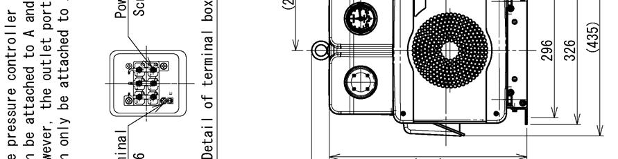
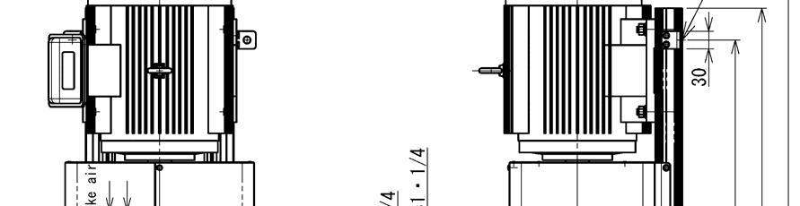
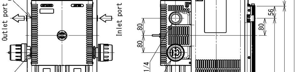
28 Dimensional Outline Drawing KRF70-V-01,04 / KRF70-VH-01,04 (unit : mm) 26
29 Dimensional Outline Drawing KRF70-B-01,04 / KRF70-BH-01,04 (unit : mm) 27

30 Dimensional Outline Drawing KRF70-VB-01,04 / KRF70-VBH-01,04 (unit : mm) 28


31 Dimensional Outline Drawing KRF110-V-01,04 (unit : mm) 29
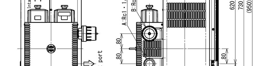
32 Dimensional Outline Drawing KRF110-B-01,04 (unit : mm) 30
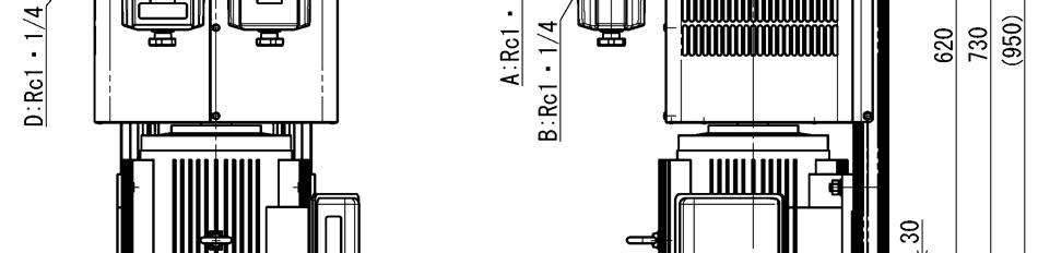
33 Dimensional Outline Drawing KRF110-VB-01,04 (unit : mm) 31
34 memo 37
35 memo 37


36 K No C DG TY
Spec.No. CBF2525-VBVB-01E-1. Orion Model CBF2525-VBVB-01. Date Aug APPD CKD DWN. Kuroiwa Yamada Takei Takahashi ORION MACHINERY CO., LTD.
 Spec.No. CBF2525-VBVB-01E-1 Orion Trade Name DRY PUMP Orion Model CBF2525-VBVB-01 Date Aug.30.2011 APPD CKD DWN Y. F. N. Y. Kuroiwa Yamada Takei Takahashi ORION MACHINERY CO., LTD. Spec.No. CBF2525-VBVB-01E-1
High Vacuum Diaphragm-Type Dry Vacuum Pump
 No 腄 26300-2-02-3 High Vacuum Diaphragm-Type Dry Vacuum Pump DTC-120 DTC-120A, 120B, 120C (According to CE) Request to Users Please read this manual thoroughly to ensure safe and effective use of the equipment.
ISP-500B. Oil-free Scroll Vacuum Pump. Instruction Manual. View our inventory. Record of Pump Information. Serial Number: Purchase date:
 ISP-500B Oil-free Scroll Vacuum Pump Instruction Manual View our inventory Serial Number: Record of Pump Information Purchase date: In Service date: Dealer information: IM-500B 1/3/07 Page 1 of 26 Important
Single Stage Rotary Vane Vacuum Pump Installation and Operation Manual RX-40 RX-63 RX-100
 V acuum Pumps Single Stage Rotary Vane Vacuum Pump Installation and Operation Manual RX-40 RX-63 RX-100 www.republicsales.com Revised 02.15 2015 Republic Sales & Manufacturing Single Stage Rotary Vane
Instruction Manual. Table of Contents. Powder Clutch, Brake MODEL ZKB-AN,BN Powder Clutch ZKB-YN,XN Powder Brake
 ZJ-267A Powder Clutch, Brake MODEL ZKB-AN,BN Powder Clutch ZKB-YN,XN Powder Brake Instruction Manual Table of Contents Cautions on Safety - - - - - - - - - - - - - - - - - 1 1. Cautions before use - -
Butterfly Valve Type 58 (PDCPD)
") Serial No. H-V074-E Butterfly Valve Type 58 (PDCPD) 700mm (28 ) User s Manual Contents (1) Be sure to read the following warranty clauses of our product 1 (2) General operating instructions 2 (3) General
Serial No. H-V074-E Butterfly Valve Type 58 (PDCPD) 700mm (28 ) User s Manual Contents (1) Be sure to read the following warranty clauses of our product 1 (2) General operating instructions 2 (3) General
Single Stage Rotary Vane Vacuum Pump Installation and Operation Manual RX-10 RX-21 RX-25
 V acuum Pumps Single Stage Rotary Vane Vacuum Pump Installation and Operation Manual RX-10 RX-21 RX-25 www.republicsales.com Revised 10.14 2014 Republic Sales & Manufacturing Single Stage Rotary Vane Vacuum
3M TM Filter Housing 1BS-T/1BS-TW Series
 READ FIRST 3M TM Filter Housing 1BS-T/1BS-TW Series Operation Manual CONTENTS Introduction 1 For Your Safety 1,2 Attention to galling or seizure of treaded portions 2 Specifications 3 Part names 4 Installation
Sediment strainer (Type Y)
") Installation,Operation and Maintenance Manual Serial No. H-V034-E-9 Sediment strainer (Type Y) Contents (1) Be sure to read the following warranty clauses of our product 1 User s Manual (2) General operating
Installation,Operation and Maintenance Manual Serial No. H-V034-E-9 Sediment strainer (Type Y) Contents (1) Be sure to read the following warranty clauses of our product 1 User s Manual (2) General operating
M-3025CB-AV Fuel Pump
 SAVE THESE INSTRUCTIONS M-3025CB-AV Fuel Pump Owner s Manual TABLE OF CONTENTS General Information... 2 Safety Instructions... 2 Installation... 3 Operation... 4 Maintenance... 4 Repair... 5 Troubleshooting...
3-Way Ball Valve Type 23H
 Serial No. H-V062-E-4 contents 3-Way Ball Valve Type 23H User s Manual (1) Be sure to read following warranty clauses of our product 1 (2) General operating instructions 2 (3) General instruction for transportation,
Lumitester PD-20 Control Kit
 日本語による取扱説明は 17 ページからとなります Lumitester PD-20 Control Kit Operation manual Thank you for purchasing the Lumitester PD-20 Control Kit. To use this kit safely and correctly, read this operation manual carefully
Hydraulic Immediate Need Power Pack
 Safety, Operation, and Maintenance Manual WARNING Improper use of this tool can result in serious bodily injury This manual contains important information about product function and safety. Please read
D Instructions/Parts. Siphon Feed Detail Spray Gun D
 Instructions/Parts D-5-55 Siphon Feed Detail Spray Gun FOR PRODUCT INFORMATION CALL: 1-800-742-7731 309991D Important Safety Instructions Read all warnings and instructions in this manual. Save these instructions.
GATE VALVES. Type P (Standard: Plug) Type S (Soft Seal) Contents. (1) Be sure to read the following warranty clauses of our product 1
 Type S (Soft Seal) Contents. (1) Be sure to read the following warranty clauses of our product 1") Serial No. H-V011-E-12 GATE VALVES Type P (Standard: Plug) Type S (Soft Seal) Contents (1) Be sure to read the following warranty clauses of our product 1 User s Manual (2) General operating instructions
Serial No. H-V011-E-12 GATE VALVES Type P (Standard: Plug) Type S (Soft Seal) Contents (1) Be sure to read the following warranty clauses of our product 1 User s Manual (2) General operating instructions
MGFHVLP. Instructions/Parts. Mini Gravity Feed System E. Part No Includes MGFHVLP Mini Gravity Feed Spray Gun and MGC 125 Gravity Cup.
 Instructions/Parts MGFHVLP Mini Gravity Feed System FOR PRODUCT INFORMATION CALL: 1-800-742-7731 309989E For gravity feed spraying of automotive colors and clears. Ideal for touch-up and detail work. Important
Diaphragm Valve Type 72
 Serial No. H-V001-E-8 Diaphragm Valve Type 72 User s Manual Contents (1) Be sure to read the following warranty clauses of our product 1 (2) General operating instructions 2 (3) General instructions for
Diaphragm Valves Type 15
 Serial No. H-V031-E-8 Diaphragm Valves Type 15 User s Manual Contents (1) Be sure to read the following warranty clauses of our product 1 (2) General operating instructions 2 (3) General instructions for
6L Oil-less Air Compressor 53103
 6L Oil-less Air Compressor 53103 Operating Instructions Please read and save these instructions before attempting to assemble, install, operate or maintain the product. Protect yourself and others by observing
T1-Titanium Non-HVLP Spray Gun
 T1-Titanium Non-HVLP Spray Gun THE SPRAY GUN PEOPLE FOR PRODUCT INFORMATION CALL: 1-800-742-7731 Important Safety Instructions Read all warnings and instructions in this manual. Save these instructions.
Digital Apex Locator. ipex OPERATION MANUAL OM-E0285E
 Digital Apex Locator ipex OPERATION MANUAL 0197 OM-E0285E The EU directive 93/42/EEC was applied in the design and production of this medical device. Thank you for purchasing the ipex. This is apex locator.
VL-100U5-E (pull cord type) VL-100EU5-E (wall switch type)
 VL-100EU5-E (wall switch type)") 1301875HF7701 Mitsubishi Lossnay Ventilator MODEL: VL-100U5-E (pull cord type) VL-100EU5-E (wall switch type) Installation Manual For Dealer and Contractor Please ensure that the separate Operating Instructions
1301875HF7701 Mitsubishi Lossnay Ventilator MODEL: VL-100U5-E (pull cord type) VL-100EU5-E (wall switch type) Installation Manual For Dealer and Contractor Please ensure that the separate Operating Instructions
AIR-COOLED DIESEL GENERATOR OWNERʼS MANUAL. This manual contains important safety information. TDG2500E TDGW7000E TDG7000SE TDG4500E
 AIR-COOLED DIESEL GENERATOR OWNERʼS MANUAL This manual contains important safety information. TDG2500E TDGW7000E TDG7000SE TDG4500E TDG8000-3 TDG7000SE-3 TDG7000E TDG8000E TDGW7000SE TDG7000E3 TDGW8000E
Instruction Manual for Direct-Drive Oil Sealed Rotary Vacuum Pump
 No.17200-2-11-1 Instruction Manual for Direct-Drive Oil Sealed Rotary Vacuum Pump Model GLD-051(S) Before using the product, be sure to read this manual. Keep this manual in a place where it can be referred
1100W PORTABLE GENERATOR
 1100W PORTABLE GENERATOR MODEL NO: G1200 PART NO: 8010110 OPERATION & MAINTENANCE INSTRUCTIONS LS0312 INTRODUCTION Thank you for purchasing this CLARKE 1100W Portable Generator. Before attempting to use
Voltmaster Centrifugal Trash Pumps
 Voltmaster Centrifugal Trash Pumps Model TSP2, TSP3 and TSP4 Owner s Manual February 2011 Table of Contents 1 Introduction............................ 1 1.1 Read before using..................... 1 1.2
WARNING: Read these instructions before using the machine GENERATOR MODEL NO: IG3500F PART NO: OPERATION & MAINTENANCE INSTRUCTIONS
 WARNING: Read these instructions before using the machine GENERATOR MODEL NO: IG3500F PART NO: 8877100 OPERATION & MAINTENANCE INSTRUCTIONS ORIGINAL INSTRUCTIONS LS0217 INTRODUCTION Thank you for purchasing
Contents H-V034-E-12. Serial No. (page) (1) Be sure to read the following warranty clauses of our product 1. (2) General operating instructions 2
 (1) Be sure to read the following warranty clauses of our product 1. (2) General operating instructions 2") Serial No. H-V034-E-12 Sediment strainer (Type Y) Contents (page) (1) Be sure to read the following warranty clauses of our product 1 User s Manual (2) General operating instructions 2 (3) General instructions
Serial No. H-V034-E-12 Sediment strainer (Type Y) Contents (page) (1) Be sure to read the following warranty clauses of our product 1 User s Manual (2) General operating instructions 2 (3) General instructions
A B 0 0 C D E 6 7 G F F H 8 9 K M O O L N I J 1
 1 2 1 5 4 3 2 2 1 6 3 8 7 1 9 4 C A B 5 0 0 D E 6 G 7 F F H 8 K 9 M O O I J L N 1 GENERAL OPERATIONAL PRECAUTIONS 1. Keep work area clean. Cluttered areas and benches invite accidents. 2. Avoid dangerous
Installation and Service Manual for RV33, RV332, RV75, RV752, RV100, RV1002
 Rotary Vane Compressors RV Series Installation and Service Manual for RV33, RV332, RV75, RV752, RV100, RV1002 Thank you for purchasing the Stratus RV series rotary vane compressor. This instruction manual
User s Manual. Automatic Switch-Mode Battery Charger
 User s Manual Automatic Switch-Mode Battery Charger IMPORTANT Read, understand, and follow these safety rules and operating instructions before using this battery charger. Only authorized and trained service
Installation,Operation and Maintenance Manual H-V016-E-10. Serial No. 目次 ( ページ ) 1. Be sure to read the following warranty clauses of our product 1
 1. Be sure to read the following warranty clauses of our product 1") Serial No. H-V016-E-10 Gauge Valve 目次 ( ページ ) 1. Be sure to read the following warranty clauses of our product 1 2. General operating instructions 2 User s Manual 3. General instructions for transportation,
Serial No. H-V016-E-10 Gauge Valve 目次 ( ページ ) 1. Be sure to read the following warranty clauses of our product 1 2. General operating instructions 2 User s Manual 3. General instructions for transportation,
Instruction Manual LAMI CORPORATION INC.
 Instruction Manual LAMI CORPORATION INC. Preface Thank you for purchasing our. This Instruction Manual (document) includes details for safe use of this product. Please read this document thoroughly before
SIP Direct Drive Oil-Lube Air Compressors - Operating & Maintenance Instructions
 SIP Direct Drive Oil-Lube Air Compressors - Operating & Maintenance Instructions Please read and fully understand the instructions in this manual before operation. Keep this manual safe for future reference.
Butterfly Valve Type 57P
 Butterfly Valve Type 57P Contents Lever Type: 50-200 mm (2-8 ) Body Material: CPVC Gear Type: 50-200mm (2-8 ) Body Material: CPVC (1) Be sure to read the following warranty clauses of our product 1 (2)
ATTENTION! READ BEFORE ATTACHING THE AIR HOSE
 Binks SV50 HVLP GRAVITY FEED SPRAY GUN & TOUCHUP GUN ATTENTION READ BEFORE ATTACHING THE AIR HOSE HVLP AIR SUPPLY REQUIREMENTS FULL SIZE GUN: 30 PSI inlet pressure provides 10 PSI at the air cap. Consumes
Filterpack FR-BFP2-(H)0.4K to (H)15K
0.4K to (H)15K") INVERTER INSTRUCTION MANUAL FR-BFP2-(H)0.4K to (H)15K 1. Product Checking... 1 2. Applicable Inverter... 1 3. Installation... 2 3.1 Inverter Installation (installation of the )...2 4. Wiring... 4 5. Main
INVERTER INSTRUCTION MANUAL FR-BFP2-(H)0.4K to (H)15K 1. Product Checking... 1 2. Applicable Inverter... 1 3. Installation... 2 3.1 Inverter Installation (installation of the )...2 4. Wiring... 4 5. Main
EVS RP6020. Instruction Manual
 Instruction Manual TDK Lambda BEFORE USING THE PRODUCT Be sure to read this instruction manual thoroughly before using this product. Pay attention to all cautions and warnings before using this product.
- click here for pricing and ordering
 www.pumpagents.com - click here for pricing and ordering No. 51-038 Mar. 01, 2006 MD-40R MD-40RX MD-40RZ(-5) Item Description Q'ty Material Part No. Part No. Part No. 1 Front Casing Unit 1 GFRPP+PTFE MD0053
Vertical Chemical Pumps
 Vertical Chemical Pumps JKD/JKT/JKH/JKP/JKV Series Instruction Manual JIEKAI INDUSTRIAL EQUIPMENT CO., LTD. 0 1. Introduction Table of Contents Model Definition... 2 Specification And Suitable Applications...
Swing Piston Compressors and Vacuum Pumps
 Swing Piston Compressors and Vacuum Pumps NPK 018 AC Pressure NPK 018 DC Pressure NPK 018 AC Vacuum NPK 018 DC Vacuum Operating and Installation Instructions Read and observe these Operating and Installation
6 Litre Oil-Less Air Compressor
 Operator s Manual 6 Litre Oil-Less Air Compressor WARNING! Before using this appliance, read the Operator s manual and follow all its safety rules and instructions. SPECIFICATION HWKAC1 1.1 kw / 1.5 HP
Swing Check Valve ASAHI AV VALVES. Contents. User s Manual. (1) Be sure to read the following warranty clauses of our product 1
 Be sure to read the following warranty clauses of our product 1") Serial No. H-V013-E-13 Swing Check Valve User s Manual Contents (1) Be sure to read the following warranty clauses of our product 1 (2) General operating instructions 2 (3) General instructions for transportation,
Serial No. H-V013-E-13 Swing Check Valve User s Manual Contents (1) Be sure to read the following warranty clauses of our product 1 (2) General operating instructions 2 (3) General instructions for transportation,
cause injury to humans and other physical damage. : Gives information that does not fall in the WARNING or CAUTION categories.
 Be sure to thoroughly read and understand the SAFETY PRES given in this section before using the equipment in order to operate the equipment correctly. The precautionary measures described in this section
Installation and Service Manual for SRC25, SRC252, SRC50, SRC502, SRC75, SRC752
 Rocking Piston Compressors Installation and Service Manual for SRC25, SRC252, SRC50, SRC502, SRC75, SRC752 Thank you for purchasing the Stratus SRC series rocking piston compressor. This instruction manual
Submersible Mixed Flow/Axial Flow Pump Model SAM Model SPM
 Instruction Manual Installation Manual Submersible Mixed Flow/Axial Flow Pump Model SAM Model SPM Thank you for your purchase of the Submersible Mixed Flow/Axial Flow Pump. Teral s Submersible Mixed Flow/Axial
Stainless Steel Rotary Drum Pump
 Please read and save this Repair Parts Manual. Read this manual and the General Operating Instructions carefully before attempting to assemble, install, operate or maintain the product described. Protect
OWNER S MANUAL SELF-PRIMING PORTABLE UTILITY PUMP
 Model 54011-0 OWNER S MANUAL SELF-PRIMING PORTABLE UTILITY PUMP Questions, problems, missing parts? Before returning to the store call AQUAPRO Customer Service 8 a.m. - 5 p.m., EST, Monday-Friday 1-844-242-2475
cause injury to humans and other physical damage. : Gives information that does not fall in the WARNING or CAUTION categories.
 Be sure to thoroughly read and understand the SAFETY PRES given in this section before using the equipment in order to operate the equipment correctly. The precautionary measures described in this section
Installation, Operation and Maintenance Manual Stancor SSD & SL Series Pumps
 Installation, Operation and Maintenance Manual Stancor SSD & SL Series Pumps EI-700-008 Rev -- Table of Contents Safety Guidelines 3 Caution 4 Wiring 4 Maintenance 4 Nameplate format 4 Prior to Operation
Instruction manual. High voltage insulation resistance tester KEW3121B/3122B
 Instruction manual High voltage insulation resistance tester KEW3121B/3122B Contents 1. Safety warnings... 1 2. Features... 5 3. Specification... 6 4. Instrument layout... 9 5. Getting started... 10 5-1
RP Instruction Manual
 Instruction Manual TDK Lambda BEFORE USING THE PRODUCT Be sure to read this instruction manual thoroughly before using this product. Pay attention to all cautions and warnings before using this product.
5.5KVA GENERATOR MODEL NO: PG6500DVES OPERATION & MAINTENANCE INSTRUCTIONS PART NO: LS0616
 5.5KVA GENERATOR MODEL NO: PG6500DVES PART NO: 8857810 OPERATION & MAINTENANCE INSTRUCTIONS LS0616 INTRODUCTION Thank you for purchasing this CLARKE 5.5KVA Generator. Before attempting to use this product,
Log Splitter. Owner/Operator Manual. Models HCWP1-26
 Log Splitter Owner/Operator Manual Models HCWP1-26 SAFETY..........................2 SAFETY WARNING SYMBOL.........3 SAFETY RULES.................. 4-5 SPECIFICATIONS................. 6 CONTROLS AND FEATURES.......
M-1115S Series Fuel Pump
 SAVE THESE INSTRUCTIONS M-1115S Series Fuel Pump Owner s Manual TABLE OF CONTENTS General Information...2 Safety Instructions...2 Installation...3 Operation...4 Maintenance...5 Repair...5 Troubleshooting...9
INSTALLATION OPERATING MAINTENANCE INSTRUCTIONS
 INSTALLATION OPERATING MAINTENANCE INSTRUCTIONS ROTARY VANE -00% OIL-FREE VACUUM PUMP OR COMPRESSOR 0 to 08 0 to 0 3060 to 3080 C CE RoHS ISO 9000:00 300 to 30 Read through carefully and understand these
Model: SPTOGT01 TRACTOR PTO GENERATOR
 www.scintex.com.au sales@scintex.com.au Model: SPTOGT01 TRACTOR PTO GENERATOR SET UP, OPERATING, AND SERVICING INSTRUCTIONS Read this material before using this product. Failure to do so can result in
SPECIFICATIONS SUBJECT TO CHANGE WITHOUT NOTICE
 PREFACE The following manual is only a guide to assist you and is not a complete or comprehensive manual of all aspects of maintaining and repairing your generator. The equipment you have purchased is
ACCUSENSE CHARGE SERIES ON/OFF BOARD FULLY AUTOMATIC BATTERY CHARGER
 ACCUSENSE CHARGE SERIES ON/OFF BOARD FULLY AUTOMATIC BATTERY CHARGER SPECIFICATIONS: *Photo for reference only* Part number 8890439 Mode Select: Selects Battery Type Refer to Section 6. IMPORTANT: READ
Swing Piston Compressors and Vacuum Pumps
 Swing Piston Compressors and Vacuum Pumps NPK 050 NPK 0100 Operating and Installation Instructions Read and observe these Operating and Installation Instructions! KNF Neuberger GmbH Alter Weg 3 D-79112
INSTRUCTION OIL PUMP. SH-110A5 MODEL No DR-110A5 MODEL No PD-110A5 MODEL No WARNING
 Doc. No. APP 004U-04 INSTRUCTION OIL PUMP SH-110A5 MODEL No.851753 DR-110A5 MODEL No.851754 PD-110A5 MODEL No.851755 WARNING Prior to operating this pump, be sure to read this operation manual for safety.
Air Release Valve (PDCPD) Air Release Valve for Water (PDCPD + Epoxy Resin Coating) User s manual. Air Release Valve. Air Release Valve for Water
 Air Release Valve for Water (PDCPD + Epoxy Resin Coating) User s manual. Air Release Valve. Air Release Valve for Water") Serial No. H-V035-E-3 Air Release Valve (PDCPD) Air Release Valve for Water (PDCPD + Epoxy Resin Coating) Contents (page) User s manual () Be sure to read the following warranty clauses of our product
Serial No. H-V035-E-3 Air Release Valve (PDCPD) Air Release Valve for Water (PDCPD + Epoxy Resin Coating) Contents (page) User s manual () Be sure to read the following warranty clauses of our product
Additional Battery Unit BUM100RE Instruction Manual
 Additional Battery Unit BUM100RE Instruction Manual This manual contains important information regarding the safe use of the BUM100RE. Please read these instructions before installing and/or using the
OPERATION MANUAL, POWER MODULE-CHARGER SYSTEM. Man Occup. Machine Occup. Cycle Time Setup Time Batch Qty. Equipment Manufacturer Qty
 Rev Description Date ECO# Document Number: OPERATION MANUAL 3/24/08 00263 Form Instructions Title Operation Description Standards OPERATION MANUAL, POWER MODULE-CHARGER SYSTEM Power Module-Charger System
Submersible Turbine Pump (Volute) STM type (T, TU, and TU3) SSTM type (TUA)
 STM type (T, TU, and TU3) SSTM type (TUA)") Instruction Manual Installation Manual Submersible Turbine Pump (Volute) STM type (T, TU, and TU3) SSTM type (TUA) Thank you for your purchase of Teral (Volute) Submersible Turbine Pump. To the customers
Instruction Manual Installation Manual Submersible Turbine Pump (Volute) STM type (T, TU, and TU3) SSTM type (TUA) Thank you for your purchase of Teral (Volute) Submersible Turbine Pump. To the customers
BATTERY & STARTER ANALYSER (BSA-12) User Manual
 User Manual") BATTERY & STARTER ANALYSER (BSA-12) User Manual Introduction BSA-12 Battery Starter Analyser does not carry internal batteries but is powered up from external DC source ranging from 9V to 15V DC. It is
BATTERY & STARTER ANALYSER (BSA-12) User Manual Introduction BSA-12 Battery Starter Analyser does not carry internal batteries but is powered up from external DC source ranging from 9V to 15V DC. It is
Air Trap TATSU2. Copyright 2013 by TLV CO., LTD. All rights reserved ISO 9001/ ISO M-02 (TATSU2) 7 August 2013.
 7 August 2013.") 172-65177M-02 (TATSU2) 7 August 2013 ISO 9001/ ISO 14001 Manufacturer Kakogawa, Japan is approved by LRQA LTD. to ISO 9001/14001 Air Trap TATSU2 Copyright 2013 by TLV CO., LTD. All rights reserved 1 Contents
172-65177M-02 (TATSU2) 7 August 2013 ISO 9001/ ISO 14001 Manufacturer Kakogawa, Japan is approved by LRQA LTD. to ISO 9001/14001 Air Trap TATSU2 Copyright 2013 by TLV CO., LTD. All rights reserved 1 Contents
3KVA DUAL VOLTAGE GENERATOR MODEL NO: PG3800DV
 3KVA DUAL VOLTAGE GENERATOR MODEL NO: PG3800DV PART NO: 8857815 OPERATION & MAINTENANCE INSTRUCTIONS LS1016 INTRODUCTION Thank you for purchasing this CLARKE 3KVA Dual Voltage Generator. Before attempting
OWNER'S MANUAL WARNING DANGER. Propane cylinders sold separately. The propane cylinder must be disconnected when this firebowl is not use.
 OWNER'S MANUAL READ BEFORE USE! Model No.: BH5003-3 Style No.: 66646 For Outdoor Use Only! Use Propane Gas Only! Propane cylinders sold separately. USE PROPANE GAS ONLY! -Do not store or use gasoline or
CO 3-WAY PNEUMATIC VALVE INSTRUCTION MANUAL 2080
 CO 3-WAY PNEUMATIC VALVE INSTRUCTION MANUAL 2080 STI S.r.l has taken every care in collecting and verifying the documentation contained in this Instruction Manual. The information herein contained are
ENGINE COOLING SYSTEM
 B ENGINE A SECTION ENGINE COOLING SYSTEM CO C D CONTENTS E PRECAUTIONS... 2 Precautions for Supplemental Restraint System (SRS) AIR BAG and SEAT BELT PRE-TEN- SIONER... 2 Precautions for Liquid Gasket...
Internet For latest information, PDF catalogs and operation manuals
 EcoRich Features Achieves a % or greater energy saving (in the pressure retained mode, comparison with Daikin products) Drastic energy savings are realized by reducing the motor rotation speed in pressure
Cordless Rechargeable Saw Instructions for Use
 Technical data Voltage: DC 10.8V Weight: 1.25Kg Stroke rate: 0-2100/min Stroke: 15mm Cutting capacity: max diameter in wood 80mm / in soft metal 7mm Charging time: Between 5.0-5.5 Hours Battery: 1.3Ah
Battery Unit BHM60PC/BHM100PC Instruction Manual
 Battery Unit BHM60PC/BHM100PC Instruction Manual For the use of UPS BH60PCW/BH100PCW This manual contains important information regarding the safe use of the BHM60PC/BHM100PC for the Backup Power Supply
KING CANADA 950W PORTABLE GENERATOR MODEL: KCG-951G INSTRUCTION MANUAL COPYRIGHT 2011 ALL RIGHTS RESERVED BY KING CANADA TOOLS INC.
 KING CANADA 950W PORTABLE GENERATOR MODEL: KCG-951G INSTRUCTION MANUAL COPYRIGHT 2011 ALL RIGHTS RESERVED BY KING CANADA TOOLS INC. WARRANTY & SERVICE INFORMATION 1-YEAR LIMITED WARRANTY FOR THIS 950W
ENGINE LUBRICATION & COOLING SYSTEMS SECTIONLC CONTENTS. ENGINE LUBRICATION SYSTEM...2 Precautions...2
 ENGINE LUBRICATION & COOLING SYSTEMS SECTIONLC CONTENTS ENGINE LUBRICATION SYSTEM...2 Precautions...2 LIQUID GASKET APPLICATION PROCEDURE...2 Preparation...2 SPECIAL SERVICE TOOLS...2 Lubrication Circuit...3
Hydraulic PTO Flow Device
 Safety, Operation, and Maintenance Manual WARNING Improper use of this tool can result in serious bodily injury This manual contains important information about product function and safety. Please read
Cordless Screwdriver
 ENGLISH Cordless Screwdriver MODEL 6796D MODEL 6796FD MODEL 6797D MODEL 6797FD MODEL 6798D MODEL 6798FD 00260 I N S T R U C T I O N M A N U A L WARNING: For your personal safety, READ and UNDERSTAND before
SPECIFICATIONS Horsepower: 1.5 HP Running Maximum PSI: 125 PSI Tank Capacity: 15 Gallons CFM: 6 40 PSI 5 90 PSI
 15 GALLON AIR COMPRESSOR Model: 7678 DO NOT RETURN TO STORE Please call 800-348-5004 for parts and service CALIFORNIA PROPOSITION 65 WARNING: You can create dust when you cut, sand, drill or grind materials
Belt Driven Compressor Operation Manual Model No. SACBD-100
 Belt Driven Compressor Operation Manual Model No. SACBD-100 www.synairgy-eu.com Contents Important Notice 3 Preparation for Usage 3 Safety Guidelines 4-5 Caution 6 Brief Description 6 Compressor Overview
Single Stage Rotary Vane Vacuum Pump Installation and Operation Manual RX-630
 V acuum Pumps Single Stage Rotary Vane Vacuum Pump Installation and Operation Manual RX-630 www.republicsales.com Revised 02.15 2015 Republic Sales & Manufacturing Single Stage Rotary Vane Vacuum Pump
INSTRUCTION MANUAL FOR LINEAR COMPRESSORS
 CONTENTS INSTRUCTION MANUAL FOR LINEAR COMPRESSORS MODEL EL-60 EL-10W EL-80-15 EL-150 EL-80-17 EL-00 EL-100 1. Parts name. Instructions -1 Prior to operation 3 - Storage and transfer 3-3 Installation 4
Cordless two speed drill/driver K 10613
 Cordless two speed drill/driver K 10613 SAFETY AND PRECAUTION 1 Consider work area environment. Do not expose tools to rain. Do not use tools in damp or wet locations Keep work area clean and well lit.
Instruction Manual. Maximum Operating Pressure 700 bar
 Remote Hydraulic Cutter Model HC-120R Maximum Operating Pressure 700 bar ABSOLUTE EQUIPMENT PTY LTD 2/186 Granite Street, GEEBUNG QLD 4034 Australia sales@absoluteequipment.com.au Phone: +61 7 3865 4006
SUBMERSIBLE MAGNETIC DRIVE PUMP SUBMERSIBLE YD-5002GWN. INSTRUCTION MANUAL Version: (for U.S.A)
") SUBMERSIBLE MAGNETIC DRIVE PUMP SUBMERSIBLE YD-5002GWN INSTRUCTION MANUAL Version: 20110510 (for U.S.A) PREFACE Thank you very much for purchasing World Chemical s improved magnetic drive pump Submersible.
SUBMERSIBLE MAGNETIC DRIVE PUMP SUBMERSIBLE YD-5002GWN INSTRUCTION MANUAL Version: 20110510 (for U.S.A) PREFACE Thank you very much for purchasing World Chemical s improved magnetic drive pump Submersible.
1200W INVERTER GENERATOR
 1200W INVERTER GENERATOR MODEL NO: IG1200 PART NO: 8877070 OPERATION & MAINTENANCE INSTRUCTIONS LS0117 INTRODUCTION Thank you for purchasing this CLARKE 1200W Inverter Generator. Before attempting to use
60V RECHARGEABLE LITHIUM-ION BATTERY
 60V RECHARGEABLE LITHIUM-ION BATTERY LB60A00/LB60A03/LB60A01/LB60A02 Owner s Manual TOLL-FREE HELPLINE: 1-855-345-3934 www.greenworkstools.com Read all safety rules and instructions carefully before operating
Motorized Two-Way Ball Valve with Screwed-End Connection
 Specifications/Instructions Motorized Two-Way Ball Valve with Screwed-End Connection General Model VY6300A/VY6300B is a series of motorized two way ball valve with screwed-end connection. Models VY6300A
Cast Iron Rotary Drum Pump
 Please read and save this Repair Parts Manual. Read this manual and the General Operating Instructions carefully before attempting to assemble, install, operate or maintain the product described. Protect
RMT1201. ORIGINAL INSTRUCTIONS Cordless Multi-Tool
 RMT1201 ORIGINAL INSTRUCTIONS Cordless Multi-Tool Important! It is essential that you read the instructions in this manual before operating this machine. Subject to technical modifications. Safety GENERAL
Solid State Relays G3RV. Model Number Structure. Ordering Information. Model Number Legend. List of Models. SSR and Socket Combinations
 Solid State Relays G3RV Slimmest OMRON plug-in SSR with maximum width 6.2 mm Long electrical life and high speed switching Large plug-in terminals for reliable connection G3RV-D (DC load) models can manage
WR 22SE WR 25SE WR25SE. Handling instructions
 WR 22SE WR 25SE WR25SE Handling instructions GENERAL POWER TOOL SAFETY WARNINGS WARNING Read all safety warnings and all instructions. Failure to follow the warnings and instructions may result in electric
Butterfly Valves ASAHI AV VALVES
 Serial No. H-V030-E-8 Butterfly Valves Type 56: 400mm (16 ) Body: PP, PVDF Type 75: 450-600mm (18-24 ) Body: PP, PVDF Type 56D: 400mm (16 ) Body: PDCPD Type 75D: 450-600 mm (18-24 ) Body: PDCPD Contents
RPS1215 ORIGINAL INSTRUCTIONS. Cordless Pruner
 RPS5 ORIGINAL INSTRUCTIONS Cordless Pruner Important! It is essential that you read the instructions in this manual before assembling, operating and maintaining the product. Subject to technical modification.
SeekTech Inductive Clamp
 Inductive Clamp Manual SeekTech Inductive Clamp! Read this Operator s Manual carefully before using this tool. Failure to understand and follow the contents of this manual may result in electrical shock,
ORIGINAL INSTRUCTIONS
 OPERATION & MAINTENANCE INSTRUCTIONS CBB200 Shown here BUFFER/POLISHER MODEL NO: CBB150, CBB200 PART NO: 6500485, 6500490 ORIGINAL INSTRUCTIONS LS0818 - ISS 1 INTRODUCTION Thank you for purchasing this
AUTOMATIC FAUCET INSTRUCTION MANUAL. Important Safeguards Precautions Model Number and Components. Before Use How to Use How to Adjust
 INSTRUCTION MANUAL NOTE TO INSTALLER : PLEASE GIVE THIS MANUAL TO THE CUSTOMER AFTER INSTALLATION. AUTOMATIC FAUCET Important Safeguards Precautions Model Number and Components Before Use How to Use How
GARDEN HOSE UTILITY PUMP
 GARDEN HOSE UTILITY PUMP MODEL #HPP360, HPP12V, 473707 MODEL #HPP360, 473707 MODEL #HPP12V ATTACH YOUR RECEIPT HERE Purchase Date SAFETY INFORMATION Please read and understand this entire manual before
No.51 Kunminghu Street, Shenyang Economic & Technical Development Zone, Shenyang, China (110141) Phone: Fax:
 Phone: Fax:") Precautions for handling the Rechargeable Valve Regulated Lead Acid Batteries This document should be read in its entirety and its content fully understood before handling or using Panasonic rechargeable
Precautions for handling the Rechargeable Valve Regulated Lead Acid Batteries This document should be read in its entirety and its content fully understood before handling or using Panasonic rechargeable
Airless Spray Gun INSTRUCTIONS DP psi (345 bar) Maximum Working Pressure
 Maximum Working Pressure") INSTRUCTIONS DP-6376 Airless Spray Gun 5000 psi (345 bar) Maximum Working Pressure INSTRUCTIONS This manual contains important warnings and information. READ AND KEEP FOR REFERENCE. Table of Contents Warnings......................................
INSTRUCTIONS DP-6376 Airless Spray Gun 5000 psi (345 bar) Maximum Working Pressure INSTRUCTIONS This manual contains important warnings and information. READ AND KEEP FOR REFERENCE. Table of Contents Warnings......................................