AST5035 Diesel Engine Setting/Locking Tool Kit.
|
|
|
- Jason Montgomery
- 5 years ago
- Views:
Transcription
 in: VOLKSWAGEN Transporter 03-08 Touareg 03-08 Multivan 04-08 AXD, AXE, BAC, BLJ, BLK, BNZ, BPC, BPD and BPE engines.")

1 AST5035 Diesel Engine Setting/Locking Tool Kit. Applications: VW GROUP 2.5 TDi Pumpe Düse Diesel engine (GEAR) in: VOLKSWAGEN Transporter Touareg Multivan AXD, AXE, BAC, BLJ, BLK, BNZ, BPC, BPD and BPE engines. IMPORTANT: Always refer to the vehicle manufacturer s service instructions, or proprietary manual, to establish the current procedures and data. Product Information Sets detail applications and use of the tools with any general instructions provided as a guide only. Kit contents/spares Item Part Number Description 1 AST5031 Crankshaft TDC Position Tool 2 AST5032 Crankshaft Locking Tool 3 AST5033 Camshaft Locking Tool 4 AST5034 Camshaft Gear Clamp 5 AST5036 Eccentric Pin Holding Tool 6 AST5037 Camshaft Gear Adjuster - AST Case + Insert AUTO SERVICE TOOLS Auto Service Tools Limited, /


2 Introduced in 2003 these 2,5L TDi Pumpe Düse engines utilise a helical-toothed spur gear set that drives the camshaft and all engine auxiliaries from the crankshaft. The engine fan is electrically driven. AST5035 Diesel Engine Timing Tool Kit Comprises: AST5031 Crankshaft TDC Position Tool AST5032 Crankshaft Locking Tool AST5033 Camshaft Locking Tool AST5034 Camshaft Gear Clamp AST5036 Eccentric Pin Holding Tool AST5037 Camshaft Gear Adjuster NOTE: The tools in this timing kit are used in a specific sequence, and it will save time and make selection of the correct tools easier if the operator reads and becomes familiar with the timing procedure beforehand. Checking the valve timing. IMPORTANT: To check the valve timing the crankshaft is positioned at TDC at cylinder number 1. 2a AST5032 Crankshaft Locking Tool AST5032 Locks the crankshaft in position with number 1 cylinder at TDC Fit AST5032 Crankshaft Locking Tool onto the crankshaft at the same time engaging the clamp pin through the engine mounting in the cylinder block using the stepped pin. NOTE: When the engine is removed from the vehicle, or the engine mounting is removed, the alternative straight pin is positioned directly into the cylinder block. 1 AST5031 Crankshaft TDC Position Tool AST5031 is used to rotate the crankshaft to the timed position. Position AST5031 Crankshaft TDC Position Tool onto the crankshaft; turn the crankshaft in the direction of engine rotation aligning the marks on AST5031 and the sealing flange. NOTE: The Crankshaft Locking Tool locates onto the crankshaft in only one position. The crankshaft is now timed in the correct position with number 1 cylinder at TDC. Remove AST5031 Position Tool 2/ b Attach the Crankshaft Locking Tool onto the crankshaft with the screw provided. NOTE: The Crankshaft Locking Tool fits in only one position on the crankshaft. If it is not possible to fit the Locking Tool, re-fit AST5031 and turn the crankshaft one revolution, in the direction of engine rotation, until the marks on AST5031 and the sealing flange align again. AUTO SERVICE TOOLS Auto Service Tools Limited, 2009


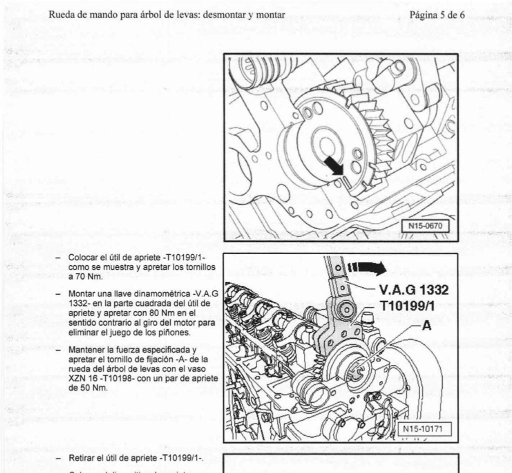
3 5 Position the crankshaft at TDC for cylinder number 1. 3 AST5033 Camshaft Locking Tool AST5032 is used to accurately align a datum slot, located in the end of the camshaft with a datum hole in the cylinder head, to hold the camshaft at the TDC position. Position AST5031 Crankshaft TDC Position Tool onto the crankshaft; turn the crankshaft in the direction of engine rotation aligning the marks on AST5031 and the sealing flange. NOTE: The Crankshaft Locking Tool fits in only one position on the crankshaft. The crankshaft is now timed in the correct position with number 1 cylinder at TDC. Fit the AST5033 Camshaft Locking Tool in position. 4 Check the position of the camshaft gear. The timing is correct when the marking arrow on the sender wheel is aligned with the upper edge of the cylinder head sealing surface as in picture 4. If the marking arrow does not align, adjustment of the valve timing will be necessary. Adjusting the valve timing. When adjusting the valve timing, removing and installing the cylinder head, removing and installing the camshafts, it is necessary to remove the camshaft drive gear Removing camshaft drive gear It will be necessary to remove the acoustic cover, cylinder head cover and the tandem pump. AUTO SERVICE TOOLS 3/7 Auto Service Tools Limited, AST5034 Camshaft Gear Clamp AST5034 Camshaft Gear Clamp is used to support the camshaft gear to allow the camshaft gear fixing bolt to be removed. Remove the outer bearing cap and position AST5034 Camshaft Gear Clamp onto the camshaft gear and tighten the four bolts to 40 Nm. Loosen the fixing bolt of the camshaft gear and remove with the tandem pump shaft. Release the four bolts securing the Camshaft Gear Clamp and remove AST5034. Remove the camshaft gear from the camshaft. Unbolt the sealing cover from the eccentric pin, removing the securing bolt and pulling the eccentric pin out


4 Remove the camshaft drive gear. IMPORTANT: Care must be taken when removing the camshaft drive gear and the compensating link. Installing camshaft drive gear 8 Fit AST5032 Crankshaft Locking Tool onto the crankshaft at the same time engaging the clamp pin through the engine mounting on the cylinder block using the stepped pin. NOTE: When the engine is removed from the vehicle, or the engine mounting is removed, the alternative straight pin is positioned directly into the cylinder block. 7 Position AST5031 Crankshaft TDC Position Tool onto the crankshaft; turn the crankshaft in the direction of engine rotation aligning the marks on AST5031 and the sealing flange. NOTE: The Crankshaft Locking Tool fits in only one position on the crankshaft. Attach the Crankshaft Locking Tool onto the crankshaft with the screw provided. NOTE: The Crankshaft Locking Tool fits in only one position on the crankshaft. If it is not possible to fit the Locking Tool, re-fit AST5031 and turn the crankshaft one revolution, in the direction of engine rotation, until the marks on AST5031 and the sealing flange align again. The crankshaft is now timed in the correct position with number 1 cylinder at TDC. Remove AST5031 Position Tool. 9 Fit AST5033 Camshaft Locking Tool in position. 4/ AUTO SERVICE TOOLS Auto Service Tools Limited, 2009
 engaging the lugs in the grooves of the guide sleeve (2).")
 and the camshaft drive gear (1) into the gear cavity from above. Refit the outer bearing cap and tighten hand tight.")
, oiling all surfaces, ensuring that the marking on the eccentric pin (5) is")
5 Install the camshaft drive gear (1) onto the guide sleeve (2) ensuring all surfaces of the guide sleeve are oiled. Install the disc (3) engaging the lugs in the grooves of the guide sleeve (2). Install the drive gear (1) with disc (3) and the guide sleeve (2) on the compensating link plate (4). 12 Guide the link plate (4) and the camshaft drive gear (1) into the gear cavity from above. Refit the outer bearing cap and tighten hand tight WARNING: The marks on the guide sleeve (2) and the link plate (4) must align AST5036 Eccentric Pin Holding Tool Install the eccentric pin (5), oiling all surfaces, ensuring that the marking on the eccentric pin (5) is vertical and uppermost; with the marking on the link plate (1) aligning with the sealing surface of the cylinder head. AUTO SERVICE TOOLS 5/7 Auto Service Tools Limited,


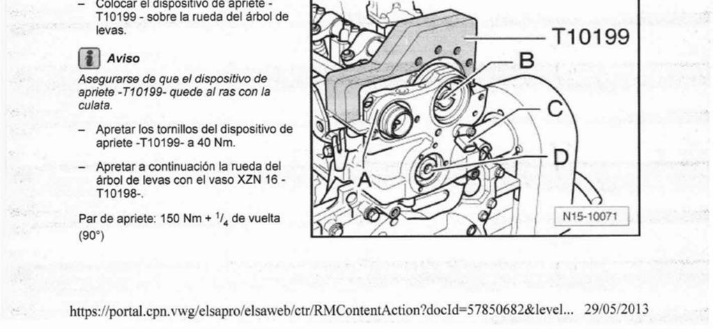
6 14 Position the camshaft gear wheel onto the camshaft ensuring that the marking arrow on the sender wheel aligns with the upper edge of the cylinder head sealing surface. AST5036 is used to turn and hold the eccentric pin in the installed position whilst securing with a new bolt. 16 Using a new bolt secure the camshaft gear wheel and the tandem pump shaft, tighten bolt finger tight. At this point the camshaft gear wheel can still turn. NOTE: Lubricate the gear wheel teeth with engine oil prior to installation. 15 Install a new securing bolt (6) (picture 11) for the eccentric pin (5) (picture 11) and tighten by hand, then unscrew back approximately one thread pitch. Position AST5036 Eccentric Pin Holding Tool with a torque wrench into the holes of the eccentric, turning the eccentric pin carefully anti-clockwise and tighten to 50Ncm Whilst holding the eccentric pin in this position, tighten new securing bolt to 20Nm +90 Remove the outer bearing cap. Install the outer bearing cap using sealant and tighten with new bolts to 8Nm / AST5037 Camshaft Gear Adjuster AST5037 is used to eliminate play in the gear train before tightening the camshaft gear securing bolt. Position AST5037 Camshaft Gear Adjuster onto the camshaft gear and tighten the three bolts to 70Nm to clamp the adjuster onto the camshaft gear. AUTO SERVICE TOOLS Auto Service Tools Limited, 2009


7 18 Using a suitable torque wrench in the square drive of the Camshaft Gear Adjuster exert a force of 80 Nm in the opposite direction of engine rotation to remove play from the gear train. Whilst maintaining this force, tighten the camshaft gear securing bolt to 50 Nm. NOTE: Tightening this camshaft gear securing bolt will require the assistance of a second mechanic. 20 Using AST5031 Crankshaft TDC Positioning Tool rotate the engine in direction of engine rotation twice until the crankshaft is set again to TDC No.1 cylinder. Refit AST5032 Crankshaft Locking Tool and AST5033 Camshaft Locking Tool to check the timing position - as described in Checking valve timing. Remove all tools. Remove the Camshaft Gear Adjuster. 19 Position AST5034 Camshaft Gear Clamp onto the camshaft gear and tighten the four bolts to 40 Nm. NOTE: Ensure that the clamp plate fits fully on to the surface of the cylinder head with no gap. Tighten camshaft gear securing bolt to 150 Nm + 90 Remove all tools. Install the tandem pump, cylinder head cover and acoustic cover. 7/ AUTO SERVICE TOOLS Auto Service Tools Limited, 2009 Auto Service Tools Ltd, Redditch, B98 0RD, England Tel: +44(0) Fax: +44(0) sales@asttools.co.uk Website:
8
9
10
11
12
13
14
15
16
DIESEL ENGINE SETTING/LOCKING KIT - VOLKSWAGEN 2.5TDi - PUMP DUSE- GEAR DRIVE. Introduction:
 型號 FB2986 VOLKSWAGEN 正時工具 DIESEL ENGINE SETTING/LOCKING KIT - VOLKSWAGEN 2.5TDi - PUMP DUSE- GEAR DRIVE Introduction: Suitable for timing gear drive engines where the camshaft, crankshaft and auxiliary
Instructions for: DIESEL ENGINE SETTING/LOCKING KIT - VOLKSWAGEN 2.5TDi - PUMP DüSE - GEAR DRIVE MODEL No: VS5035. Applications: Kit contents
 Instructions for: DIESEL ENGINE SETTING/LOCKING KIT - VOLKSWAGEN 2.5TDi - PUMP DüSE - GEAR DRIVE MODEL No: VS5035 Thank you for purchasing a Sealey product. Manufactured to a high standard this product
AST4510A Petrol Engine Twin Camshaft Setting/Locking Tool Kit
 AST4510A Petrol Engine Twin Camshaft Setting/Locking Tool Kit Applications: FIAT 1.2 16v. & 1.4 16v. Twin Cam Petrol engines in FIAT New 500 Panda Punto Grande Punto Idea Linea Palio Weekend New Bravo
AST4830 Diesel Engine Setting/Locking Tool Kit
 AST4830 Diesel Engine Setting/Locking Tool Kit Applications: FORD 1.4TDCi, 1.6TDCi, 1.8Di/TDdi/TDCi, 2.0TDCi (Belts). Timing Belt Replacement Applications on DURATORQ diesel engines in FORD Fiesta/Courier
AST4950 Petrol Engine Setting/Locking Tool Kit
 AST4950 Petrol Engine Setting/Locking Tool Kit Applications: FIAT 1.2 & 1.4 8v. Petrol engines in FIAT New 500 Idea Grande Punto Linea Doblo Panda* 1.2 8v. 169A4.000, 199A4.000 1.4 8v. 350A1.000 *1.2 8v.
AST4950 Petrol Engine Setting/Locking Tool Kit
 AST4950 Petrol Engine Setting/Locking Tool Kit Applications: FIAT 1.2 & 1.4 8v. Petrol engines in FIAT New 500 Idea Grande Punto Linea Doblo Panda* 1.2 8v. 169A4.000, 199A4.000 1.4 8v. 350A1.000 *1.2 8v.
Removing and installing toothed belt
 Page 1 of 10 Special tools and workshop equipment required Diesel injection pump locking pin -3359- (2x) Pin wrench -T10020- Crankshaft stop -T10050- for engines with circular crankshaft sprocket Locking
Removing and installing cylinder head Removing, installing and tensioning toothed belt
 Page 1 of 10 Removing and installing cylinder head Removing, installing and tensioning toothed belt Special tools, workshop equipment, test and measuring appliances and auxiliary items required 3359 Locking
Diesel Engine Setting / Locking & Injection Pump Removal / Installation Kit Auto Service Tools Ltd
 AST5130 Diesel Engine Setting / Locking & Injection Pump R+I Kit AST5130 Kit Option: AST5135 Updates AST4730 to include H.P. pump removal on 2.4L engines in Transit and Defender, (2006 onwards) with Denso
2003 Cadillac CTS V6-3.2L VIN N
 1 of 16 5/11/2013 11:18 AM 2003 Cadillac CTS V6-3.2L VIN N Vehicle» Engine, Cooling and Exhaust» Engine» Timing Belt» Service and Repair» Timing Belt Replacement Timing Belt Replacement Tools Required
Engine, disassembly and
 Page 1 of 13 13-1 Engine, disassembly and assembly Ribbed belt, removing and installing Removing - Remove noise insulation -arrows-. - Remove bumper Repair Manual, Body Exterior, Repair Group 63 - Move
REMOVAL & INSTALLATION
 REMOVAL & INSTALLATION TIMING BELT Removal 1. Disconnect negative battery cable. On Millenia, raise and support vehicle. Remove right front wheel. Remove lower engine covers. 2. On all models, remove accessory
- 1/7 - Copyright Litens Automotive Group All rights reserved.
 Caution: The procedure to access the timing belt tensioner and all other timing driven components must be done according to the car manufacturer s guidelines. Engine temperature: 1. The tensioner must
AST4404C. Petrol Engine Twin Camshaft Setting/Locking Tool Set. Applications:
 AST4404C Petrol Engine Twin Camshaft Setting/Locking Tool Set s: Crankshaft Pulley Remover & Installer Set & Crankshaft Pulley Holding Tool Applications: FORD 1.25, 1.4, 1.6, 1.7, 1.8 & 2.0 Twin Cam 16v.
Camshaft. vw-wi://rl/v.en-us.k wi:: xml?xsl=3. Special tools and workshop equipment required
 Page 1 of 9 Camshaft Special tools and workshop equipment required Diesel Injection Pump Locking Pin -3359- Counterhold - Camshaft Gear -T10051- Puller - Camshaft Sprocket -T10052- Camshaft Fitting Tool
Volkswagen New Beetle 2.0 Liter 4-cyl General, Engine (Engine Code AEG) 13 Engine-Crankshaft, Cylinder block (Page GR-13)
 13 Engine-Crankshaft, Cylinder block (Page GR-13)") 13 Engine-Crankshaft, Cylinder block (Page GR-13) Engine, disassembly and assembly 10-222 A/21 guide from 10-222 A support tool, modifying Ribbed belt, removing and installing Semi-automatic toothed belt
13 Engine-Crankshaft, Cylinder block (Page GR-13) Engine, disassembly and assembly 10-222 A/21 guide from 10-222 A support tool, modifying Ribbed belt, removing and installing Semi-automatic toothed belt
REMOVAL & INSTALLATION
 REMOVAL & INSTALLATION TIMING BELT Removal (Esteem) 1. Disconnect negative battery cable. Remove right side engine under cover. Remove power steering and A/C compressor drive belts. 2. Remove A/C compressor
RECOMMENDET INSTALLATION PROCEDURE Timing Belt Tensioner for Aftermarket OPEL 2.0L SOHC, Fam. 2 (Revision date: 04/27/1999)
") 1. Allow the engine and tensioner to stabilize to the same relative ambient temperature before installing a tensioner for proper belt tension adjustment. Do not attempt to install a cool tensioner onto
1. Allow the engine and tensioner to stabilize to the same relative ambient temperature before installing a tensioner for proper belt tension adjustment. Do not attempt to install a cool tensioner onto
AST5080 Diesel Engine Overhaul Timing Tool Kit
 AST5080 Diesel Engine Overhaul Tool Kit Kit Options: AST5085 Engine Setting/Locking Tool Set (Camshaft Setting & Flywheel Locking Tools) AST5086 Engine Timing Adjustment Tool Set (Camshaft & Crankshaft
Recommended Installation Procedure (11 DEC 09) ATech Timing Belt Tensioner (979847/901) VW 1.6/2.0L L4 EA189 CR Engine
 ATech Timing Belt Tensioner (979847/901) VW 1.6/2.0L L4 EA189 CR Engine") Initial Preparation: Caution: The procedure to access the timing belt tensioner and all other timing driven components must be done according to VW s guidelines. The mounting of the TBT is done on the
Initial Preparation: Caution: The procedure to access the timing belt tensioner and all other timing driven components must be done according to VW s guidelines. The mounting of the TBT is done on the
Repair Manual VW 02J gearbox. INA GearBOX
 Repair Manual VW 02J gearbox INA GearBOX Special tools Pipe section, 50 mm: Press fitting of synchronizer body for third/fourth gear. Assembly of support bearing for input and output shaft. Part number:
Fig. 195: Positioning Timing Chain On Exhaust Camshaft Courtesy of BMW OF NORTH AMERICA, INC.
 Fig. 195: Positioning Timing Chain On Exhaust Camshaft Install camshafts so that cam tips on inlet and exhaust valves on 1st cylinder face one another. Refer to 11 31 001 REPLACING CAMSHAFT (M52TU / M54
Recommended Installation Procedure Timing Belt Tensioner (979597) 2.0L DOHC, RENAULT F4R Turbo, F4R L DOHC, RENAULT F4P720 (05/18/2004)
 2.0L DOHC, RENAULT F4R Turbo, F4R L DOHC, RENAULT F4P720 (05/18/2004)") Caution: The procedure to access the timing belt tensioner and all other timing driven components must be done according to the car manufacturer s guidelines. Engine temperature: 1. The tensioner must
Caution: The procedure to access the timing belt tensioner and all other timing driven components must be done according to the car manufacturer s guidelines. Engine temperature: 1. The tensioner must
TIMING BELT TENSIONER FOR AFTERMARKET TENSIONER P/N FORD U.K. 1.8L 4-Cyl. Diesel Revision date: 06/17/1999
 1. Failure to set belt tension correctly to this procedure will result in premature engine failure! 2. The Auto-tensioner is a thermal expansion compensation device so tensioning should only be carried
AST5045 Timing Chain Service Tool Set
 AST5045 Timing Chain Service Tool Set Applications: BMW.8,.0,.5, 3.0 and BMW Mini / Citroën - Peugeot.4 and.6 Petrol engines (Chain) in: BMW 8i E87 (04-07) 0i E87 (04-07) 36i E46 (0-05) 36ti Compact E46
1992 Mitsubishi 3000GT VR-4
 TIMING BELT Removal (Diamante SOHC) 1. Remove left front and left side splash shields. Using engine hoist, lift engine just enough to remove weight from engine mounts. Remove drive belts. Remove A/C tensioner
3/6/2017 Timing Chain Service and Repair, Removal and Replacement: Valve Timing, Installing and Adjusting
 Valve timing, adjusting Special tools and equipment - T10068 Camshaft bar - T10069 Counter support - VAG 1331 Torque wrench (5-50 Nm) - VAG 1332 Torque wrench (40-200 Nm) - AMV 174 004 01 Sealing compound
TOOTHED DRIVE BELT, REMOVING, INSTALLING AND TENSIONING
 2005 Audi A4 Sedan (8E2) L4-1.8L Turbo (AMB) Vehicle > Engine, Cooling and Exhaust > Engine > Timing Components > Timing Belt > Service and Repair > Removal and Replacement TOOTHED DRIVE BELT, REMOVING,
2003 Saturn Vue. SATURN 3.0L V6 DOHC - L-Series After VIN & Vue
 TIMING BELT Removal 1. Disconnect negative battery cable. Remove air cleaner assembly. 2. Raise and support vehicle. Remove right front wheel. Remove lower front splash shield. 3. Lower vehicle. Loosen,
Engine Dismantle and Assemble ( )
") Engine Dismantle and Assemble ( 34 8) Special Tools 5 053 Slide hammer 47 Vibration damper remover 47 5053 00 Splined head socket, cylinder head bolts 87 Mounting stand with geared drive 00 059C Installer
Engine Dismantle and Assemble ( 34 8) Special Tools 5 053 Slide hammer 47 Vibration damper remover 47 5053 00 Splined head socket, cylinder head bolts 87 Mounting stand with geared drive 00 059C Installer
Removing and installing cylinder head
 31 30 29 28 27 26 25 24 23 22 1 2 3 11 12 10 4 9 5 6 7 8 Removing and installing cylinder head Checking compression pressure page 15-24. Notes: When installing a replacement cylinder head with a mounted
Recommended Installation Procedure (25 MAY 07) ATech Timing Belt Tensioner (979778) FIAT FIRE 8-valve 1.2/1.4L Engine
 ATech Timing Belt Tensioner (979778) FIAT FIRE 8-valve 1.2/1.4L Engine") Caution: The procedure to access the timing belt tensioner and all other timing driven components must be done according to the car manufacturer s guidelines. Engine temperature: 1. The tensioner must
Caution: The procedure to access the timing belt tensioner and all other timing driven components must be done according to the car manufacturer s guidelines. Engine temperature: 1. The tensioner must
Wheel bearing housing, removing and installing
 Page 1 of 17 40-54 Wheel bearing housing, removing and installing Removing - Remove wheel trim. On light alloy wheels use puller in vehicle tool kit to remove trim cap. - Remove bolt for drive axle. WARNING!
Recommended Installation Procedure ATech Timing Belt Tensioner DaimlerChrysler PL, PT, JR 2.0L 4-Cyl. Engine (10/27/2003)
") Initial Preparation: Caution: The procedure to access the timing belt tensioner and all other timing driven components must be done according to DAIMLERCHRYSLER PL s guidelines. The mounting of the TBT
Initial Preparation: Caution: The procedure to access the timing belt tensioner and all other timing driven components must be done according to DAIMLERCHRYSLER PL s guidelines. The mounting of the TBT
Engine, disassembling and
 Page 1 of 38 13-1 Engine, disassembling and assembling Lock carrier, moving into service position Special tools and equipment 3369 support tool 1 - Bolts 2 - Bolts 3 - Bolts 4 - Bolts 5 - Bore 45 Nm (33
Timing belt change. Timing belt change
 Timing belt change Put 2 new Gates T275 timing belts on today. Tensioner drilled smooth and tight with less than 16,000 miles on her decided not to change the tensioners just the belts. You'll need some
GM 6-Cylinder Cam Tool Set 3.0L and 3.2L Operating Instructions
 GM 6-Cylinder Cam Tool Set 3.0L and 3.2L Operating Instructions Set Includes: Locking Tool... 536594 Locking Tool... 536595 Crankshaft Holding Tool... 536596 Alignment Gauge... 536608 Belt Installation
1. Disconnect negative battery cable. 2. Remove upper and lower front timing belt covers..
 BELT AND SPROCKETS-TIMING REMOVAL TIMING BELT Zoom 1. Disconnect negative battery cable. 2. Remove upper and lower front timing belt covers.. CAUTION: When aligning crankshaft and camshaft timing marks
1 of 10 2/10/2017 5:20 PM
 1 of 10 2/10/2017 5:20 PM Crankshaft Pulley Removal NOTICE: Do not loosen or remove the crankshaft pulley bolt without first installing the special tools as instructed in this procedure. The crankshaft
Sealing flanges and flywheel/drive plate, removing and installing
 Page 1 of 20 13-47 Sealing flanges and flywheel/drive plate, removing and installing Note: For repairs to the clutch: Repair Manual, 5 Spd. Manual Transmission 012/01W Front Wheel Drive, Repair Group 30
Crankshaft, Remove and Install (Engine Removed) (Z 22 SE)
 (Z 22 SE)") Page 1 of 36 Crankshaft, Remove and Install (Engine Removed) (Z 22 SE) Remove 1. Remove the engine Note: See operation "Engine, Remove and Install". 2. Separate the manual transmission from the engine.
Page 1 of 36 Crankshaft, Remove and Install (Engine Removed) (Z 22 SE) Remove 1. Remove the engine Note: See operation "Engine, Remove and Install". 2. Separate the manual transmission from the engine.
TIMING BELT AND SPROCKET(S) REMOVAL - TIMING BELT
 REMOVAL - TIMING BELT") TIMING BELT AND SPROCKET(S) REMOVAL - TIMING BELT 1. Disconnect negative battery cable. 2. Raise vehicle on hoist. Remove right front wheel. 3. Remove belt splash shield. 4. Remove accessory drive belts.
TIMING BELT AND SPROCKET(S) REMOVAL - TIMING BELT 1. Disconnect negative battery cable. 2. Raise vehicle on hoist. Remove right front wheel. 3. Remove belt splash shield. 4. Remove accessory drive belts.
Timing Chain, Balancer Shaft, Replace (Z 22 SE)
") Page 1 of 34 Timing Chain, Balancer Shaft, Replace (Z 22 SE) Remove 1. Open the bonnet. 2. Disconnect the battery. 3. Open the engine cover (1). 4. Detach the engine cover. 6 bolts (2) and (3) 5. Release
Page 1 of 34 Timing Chain, Balancer Shaft, Replace (Z 22 SE) Remove 1. Open the bonnet. 2. Disconnect the battery. 3. Open the engine cover (1). 4. Detach the engine cover. 6 bolts (2) and (3) 5. Release
Toothed belt, removing and installing
 Toothed belt, removing and installing Special Tools and Equipment ^ 3212 spanner wrench ^ 3387 pin wrench ^ T40011 pin ^ T40026 locking pin ^ T40028 socket ^ T40030 camshaft adjuster gauge Removing Lock
Service and Repair. a. Remove the 2 nuts and 2 upper radiator support. b. Lift out the radiator and cooling fan assembly.
 Service and Repair REPLACEMENT 1. SEPARATE BATTERY NEGATIVE TERMINAL 2. REMOVE AIR CLEANER INLET NO.1 3. DRAIN ENGINE COOLANT 4. REMOVE V-BANK COVER 5. REMOVE INTAKE AIR CONNECTOR PIPE 6. REMOVE ENGINE
ALLDATA Online Ford Focus L4-2.0L DOHC VIN 5 - Service and Repair. Service and Repair
 Page 1 of 22 Service and Repair NOTE: Ford does not provide camshaft gear timing marks, or information to perform timing belt service without the special tools shown in this procedure. Timing Belt Special
TIMING BELT (4A FE) COMPONENTS
 COMPONENTS") EM30 Timing Belt (4AFE) TIMING BELT (4AFE) COMPONENTS REMOVAL OF TIMING BELT 1. REMOVE RH FRONT WHEEL 2. REMOVE RH ENGINE UNDER COVER 3. REMOVE WASHER TANK 4. LOOSEN WATER PUMP PULLEY BOLTS AND REMOVE
EM30 Timing Belt (4AFE) TIMING BELT (4AFE) COMPONENTS REMOVAL OF TIMING BELT 1. REMOVE RH FRONT WHEEL 2. REMOVE RH ENGINE UNDER COVER 3. REMOVE WASHER TANK 4. LOOSEN WATER PUMP PULLEY BOLTS AND REMOVE
Timing Belt. Special Tool(s) / General Equipment Alignment Peg, Crankshaft Locking Tool, Flywheel Adapter for
 / General Equipment Alignment Peg, Crankshaft Locking Tool, Flywheel Adapter for") Special Tool(s) / General Equipment 303-1059 Alignment Peg, Crankshaft Timing Belt 303-393 Locking Tool, Flywheel 303-393-01 Adapter for 303-393 303-735 Alignment Peg, Camshaft Trolley Jack Removal 1.
Special Tool(s) / General Equipment 303-1059 Alignment Peg, Crankshaft Timing Belt 303-393 Locking Tool, Flywheel 303-393-01 Adapter for 303-393 303-735 Alignment Peg, Camshaft Trolley Jack Removal 1.
SISU DP-330 DRIVE GEAR. Maintenance Manual
 SISU DP-330 DRIVE GEAR Maintenance Manual Sisu Axles, Inc. Autotehtaantie 1 PO Box 189 Fin-13101 Hameenlinna Finland Phone +358 204 55 2999 Fax +358 204 55 2900 DP330DG.PDF (3/2007) TABLE OF CONTENTS
Accurate guidelines for longer engine life
 VOLKSWAGEN VOLVO Issue 16 2013 VKMC 01270 VKMC 01258-1 VKMC 01258-2 Accurate guidelines for longer engine life Many technicians are taking chances by not following all the manufacturer recommendations
LuK Repair Solution for manual transmissions. Disassembly and assembly Special tool/failure diagnosis VW 02J
 LuK Repair Solution for manual transmissions Disassembly and assembly Special tool/failure diagnosis VW 02J The content of this brochure shall not be legally binding and is for information purposes only.
1. Remove the crankshaft pulley, engine coolant pump pulley and drive belt. 2. Remove the timing belt cover.
 DISASSEMBLY 1. Remove the crankshaft pulley, engine coolant pump pulley and drive belt. 2. Remove the timing belt cover. 3. Turn the crankshaft clockwise and align the timing marks so as to bring the No.
Fig. 1: Remove the bolts which fasten the upper timing belt cover... Fig. 2:... and remove the cover
 Show Timing Belt and Covers REMOVAL & INSTALLATION 1983 87 626 NOTE: For access, safely support the car, then remove the right front wheel and splash shield. 1. Loosen the alternator mounting bolts and
Motronic ignition system, servicing
 Page 1 of 25 28-2 Motronic ignition system, servicing Note: Motronic Engine Control Module (ECM) J220* with connector page 24-9, item 16. 1 - Highvoltage ignition cable Ignition secondary circuit Check
Master Engine Timing Tool Set
 Master Engine Timing Tool Set Ford K 10551 www.kamasatools.com Pack Layout AC V O B C U D M Z S J W W N F Y K/L Q T AD P A H R AB AA E X G I Component identity Part No. OEM Ref Description A 23002-45D
Lubrication system components, removing and installing
 17-1 Lubrication system components, removing and installing Note: If large quantities of metal particles or other deposits (caused, for example, by partial seizure of the crankshaft or conrod bearings)
Recommended Installation Procedure (31 MARCH 2010) ATech Timing Belt Tensioner (979004) EA T 20 Valve Longitudinal Engine
 ATech Timing Belt Tensioner (979004) EA T 20 Valve Longitudinal Engine") Caution: The procedure to access the timing belt tensioner and all other timing driven components must be done according to the car manufacturer s guidelines. Engine temperature: 1. The tensioner must
Caution: The procedure to access the timing belt tensioner and all other timing driven components must be done according to the car manufacturer s guidelines. Engine temperature: 1. The tensioner must
ATech Timing Belt Tensioner (979572) VM MOTORI 2.5L Diesel, Common Rail Engine
 VM MOTORI 2.5L Diesel, Common Rail Engine") Caution: The procedure to access the timing belt tensioner and all other timing driven components must be done according to the car manufacturer s guidelines. Engine temperature: 1. The tensioner must
Caution: The procedure to access the timing belt tensioner and all other timing driven components must be done according to the car manufacturer s guidelines. Engine temperature: 1. The tensioner must
2003 Hyundai Truck Santa Fe V6-3.5L
 Page 1 of 12 2003 Hyundai Truck Santa Fe V6-3.5L Vehicle» Engine, Cooling and Exhaust» Engine» Timing Belt» Service and Repair Page 2 of 12 REMOVAL 1. Remove the wheel of passenger side. 2. Remove the
Valvetrain, servicing
 Page 1 of 51 15-32 Valvetrain, servicing Note: Cylinder heads with small cracks between the valve seats that are less than 0.3 mm (0.012 in.) wide and/or between one valve seat and only the first 4 threads
Chapter 5 Part B: Ignition system - transistorised type
 5B 1 Chapter 5 Part B: Ignition system - transistorised type Contents Coil - testing........................................... 9 Distributor - overhaul..................................... 7 Distributor
REMOVAL & INSTALLATION
 REMOVAL & INSTALLATION TIMING BELT Removal 1. Disconnect negative battery cable. Rotate engine clockwise and position cylinder No. 1 on TDC of compression stroke. Ensure "O" mark on crankshaft pulley aligns
DISASSEMBLY. SORENTO(BL) > 2004 > G 3.5 DOHC > Engine Mechanical System
 > 2004 > G 3.5 DOHC > Engine Mechanical System") SORENTO(BL) > 2004 > G 3.5 DOHC > Engine Mechanical System DISASSEMBLY 1. Remove the engine cover. 2. Disconnect the battery negative terminal. 3. Disconnect the radiator lower hose. 4. Disconnect the
SORENTO(BL) > 2004 > G 3.5 DOHC > Engine Mechanical System DISASSEMBLY 1. Remove the engine cover. 2. Disconnect the battery negative terminal. 3. Disconnect the radiator lower hose. 4. Disconnect the
URGENT : Ensure that the precautions relating to safety and cleanliness are adhered to (refer to the brochure: RECOMMENDATIONS - PRECAUTIONS).
.") PAGE 1 - b1eg1xp0 - removing - refitting timing belt removing - refitting timing belt INJECTION ES9J4S URGENT Ensure that the precautions relating to safety and cleanliness are adhered to (refer to the
PAGE 1 - b1eg1xp0 - removing - refitting timing belt removing - refitting timing belt INJECTION ES9J4S URGENT Ensure that the precautions relating to safety and cleanliness are adhered to (refer to the
Recommended Installation Procedure ATech Timing Belt Tensioner and AUDI 2.0L 4V FSI & TFSI Engine (19 January 2015)
") The procedure to access the timing belt tensioner and all other timing driven components must be done according to the car manufacturer s guidelines. Engine temperature: 1. The tensioner must be installed
The procedure to access the timing belt tensioner and all other timing driven components must be done according to the car manufacturer s guidelines. Engine temperature: 1. The tensioner must be installed
Timing Belt: Service and Repair Timing Belt Replacement
 2003 Saturn Truck VUE V6-3.0L VIN B Copyright 2007, ALLDATA 9.50 Page 1 Timing Belt: Service and Repair Timing Belt Replacement Removal Procedure 1. Remove the front timing belt cover. 2. Rotate the crankshaft
Timing Belt: Service and Repair
 2000 Hyundai Sonata L4-2.4L Page 1 Timing Belt: Service and Repair REMOVAL 1. Remove the crankshaft pulley, engine coolant pump pulley and drive belt. 2. Remove the timing belt cover. 2000 Hyundai Sonata
2001 ACCORD - Timing Belt and Balancer Belt Installation
 2001 ACCORD - Timing Belt and Balancer Belt Installation Special Tools Required Holder Handle 07JAB-001020A Holder Attachment, 50 mm, Offset 07MAB-PY3010A Socket, 19 mm 07JAA-001020A or a commercially
Shown on model Bolts 6 Oil lines 5 Screw 7 Adjusting screw Shown on model 209
 AR46.20-P-0003Q Replace bottom radial shaft sealing ring on control head 4.5.07 MODEL 203, 209 except CODE (213) Speed-sensitive power steering MODEL 215, 220 Shown on model 209 1 Clamps 2 Bellows 3 Inner
M52tu-M54 VANOS Assembly & Timing Using G.A.S. Professional Cam Tool Kit
 Home BMW Solutions Porsche Solutions DIY Tech Engine Services Dyno Services Machining About Contact Store Tool Rental M52tu-M54 VANOS Assembly & Timing Using G.A.S. Professional Cam Tool Kit This procedure
ATech Timing Belt Tensioner (979756) PSA EW10A 2.0L Engine
 PSA EW10A 2.0L Engine") Caution: The procedure to access the timing belt tensioner and all other timing driven components must be done according to the car manufacturer s guidelines. Engine temperature: 1. The tensioner must
Caution: The procedure to access the timing belt tensioner and all other timing driven components must be done according to the car manufacturer s guidelines. Engine temperature: 1. The tensioner must
SPECIFICATIONS TEST AND ADJUSTMENT SPECIFICATIONS SPECIFICATIONS ENGINE FD620D, K SERIES
 ENGINE FD620D, K SERIES SPECIFICATIONS SPECIFICATIONS TEST AND ADJUSTMENT SPECIFICATIONS Engine Oil Pressure Sensor Activates............................... 98 kpa (14.2 psi) Oil Pressure While Cranking
HAZET-WERK HÖCHSTE TECHNOLOGIE IN DER WERKZEUGFERTIGUNG SEIT 1868 HIGHEST TECHNOLOGY IN TOOL MANUFACTURE SINCE 1868
 HAZET-WERK HÖCHSTE TECHNOLOGIE IN DER WERKZEUGFERTIGUNG SEIT 1868 HIGHEST TECHNOLOGY IN TOOL MANUFACTURE SINCE 1868 2588/19 3488/8 Betriebsanleitung Betriebsanleitung Werkzeug-Zusatzsortiment Werkzeug-Sortiment
SPECIFICATIONS TEST AND ADJUSTMENT SPECIFICATIONS SPECIFICATIONS ENGINE FD620D, K SERIES
 TEST AND ADJUSTMENT Engine Oil Pressure Sensor Activates............................... 98 kpa (14.2 psi) Oil Pressure While Cranking (Minimum).......................... 28 kpa (4 psi) Oil Pressure.....................................
Repairs after which the ring gear must be adjusted Page Drift VW 295
 Page 1 of 15 39-52 Ring gear, adjusting (Adjusting differential) Repairs after which the ring gear must be adjusted Page 39-37. Special tools, testers and auxiliary items Drift VW 295 Dial gauge extension
Fiat X1/9 1500cc Engine Timing Belt Replacement, Cam Timing and Static Ignition Timing. Photos courtesy of Don Doan.
 Fiat X1/9 1500cc Engine Timing Belt Replacement, Cam Timing and Static Ignition Timing. Photos courtesy of Don Doan. Introduction This document outlines how to replace a timing belt on a Fiat X1/9 1500cc
MGA Twin Cam Engine Assembly.
 MGA Twin Cam Engine Assembly. The following article is a collection of notes of things to be observed in the assembling of MGA Twin Cam engines. To be read in conjunction with the Workshop Manual. It does
2003 Hyundai Sonata LX
 TIMING & COUNTERBALANCE SHAFT BELTS Removal CAUTION: DO NOT rotate engine counterclockwise (as viewed from timing belt end of engine). If reusing timing belt, place reference mark on timing belt to indicate
Timing Belt: Service and Repair Timing Belt Replace. Timing Belt Removal
 1998 Toyota Corolla DX Sedan 4-Door L4-1762cc 1.8L DOHC MFI Page 1 Timing Belt: Service and Repair Timing Belt Replace Timing Belt Removal SPECIAL SERVICE TOOL (SST) REQUIRED ^ 09213-70010 Crankshaft Pulley
Timing Belt: Service and Repair 2002 Acura Truck MDX V6-3.5L
 Timing Belt: Service and Repair 2002 Acura Truck MDX V6-3.5L Timing Belt Removal Special Tools Required - Holder handle 07JAB-001020A - Holder attachment, 50 mm, offset 07MAB-PY3010A - Socket, 19 mm 07JAA-001020A
Engine. Special Tool(s) Adapter for (T97T-6256-A) Adapter for (T97T-6256-D)
 Adapter for (T97T-6256-A) Adapter for (T97T-6256-D)") SECTION 303-01A: Engine 4.0L SOHC 2009 Mustang Workshop Manual ASSEMBLY Procedure revision date: 05/10/2010 Engine Special Tool(s) Adapter for 303-564 303-578 (T97T-6256-A) Adapter for 303-577 303-576
SECTION 303-01A: Engine 4.0L SOHC 2009 Mustang Workshop Manual ASSEMBLY Procedure revision date: 05/10/2010 Engine Special Tool(s) Adapter for 303-564 303-578 (T97T-6256-A) Adapter for 303-577 303-576
AJV8 Engine Assembly. AJV8 Engine Assembly
 AJV8 Engine Assembly Contents Cylinder Block Dowels, Plugs and Pipes 2 4 Crankshaft Bearing and Cylinder Bore Dimensions 5 9 Bearing Measuring 6 Engine Dimensions and Codes 6 7 Main Bearing Selection Chart
The EFL 2000/1 & 2 User Guide Test Sieve Shaker. Contents
 The EFL 2000/1 & 2 User Guide Test Sieve Shaker ISSUE 04-02 Contents Description Page 1 Setting Up: 2-8 Unpacking 2 Assembly 3 Clamping Assembly 4 Electrical Connections 5 Sieve Stacking 6 8 Operating
AR05.20-P-7201AMG Remove/install camshaft adjusters ENGINES 156.### ## as of
 AR05.20-P-7201AMG Remove/install camshaft adjusters 2.3.10 Shown on right cylinder head model 211 P05.20-2276-09 01 Holding device 1 Cylinder head covers 8 Cap Y49/5 Intake camshaft solenoid, right 2 Camshafts
Instructions for: Diesel Engine Setting/Locking Tool Kit Renault dci Engines. Model No: VS4760.V3 1. SAFETY INSTRUCTIONS
 Instructions for: Diesel Engine Setting/Locking Tool Kit Renault dci Engines Model No: VS4760.V3 Thank you for purchasing a Sealey product. Manufactured to a high standard this product will, if used according
SIDI Camshaft Position Actuator Replacement
 BLOCK AND WEDGE TIMING CHAIN RETAINER USER GUIDE SIDI Camshaft Position Actuator Replacement Removal Procedure 1. Remove the camshaft cover. 2. Remove the camshaft position actuator solenoid valve solenoid
SISU MP-330 DRIVE GEAR. Maintenance Manual
 SISU MP-330 DRIVE GEAR Maintenance Manual Sisu Axles, Inc. Autotehtaantie 1 PO Box 189 Fin-13101 Hameenlinna Finland Phone +358 204 55 2999 Fax +358 204 55 2900 MP330DG.PDF (4/2007) TABLE OF CONTENTS
disc brake axle with WABCO calipers
 1 2 disc brake axle with WABCO calipers 3 4 disc brake axle with WABCO calipers 5 6 disc brake axle with WABCO calipers IMT axles are supplied as non-cambered and are within the limits of a 2 minute negative
D8 - Distributor. D9 - Auxiliary unit belts
 D8 - Distributor l ubricate Lubricate the distributor shaft sparingly (1-2 drops of oil) D9 - Auxiliary unit belts check/adjust Applies to engines which do not have multi-tooth belts Check belt tension.
Valve gear, servicing
 Page 1 of 62 15-1 Valve gear, servicing WARNING! Do not re-use any fasteners that are worn or deformed in normal use. Some fasteners are designed to be used only once, and are unreliable and may fail if
 Page 1 of 23 303-01C Engine - 3.2L Duratorq-TDCi (148kW/200PS) - Puma 2011-2014 Ranger Assembly Procedure revision date: 07/21/2016 Special Tool(s) / General Equipment Engine Base Part Number: 6L084 100-002
REMOVAL & INSTALLATION
 REMOVAL & INSTALLATION CAUTION: This application is an interference engine. Do not rotate camshaft or crankshaft when timing belt is removed, or engine damage may occur. TIMING BELT Removal 1. Disconnect
1 of 15 1/26/2017 8:57 AM
 1 of 15 1/26/2017 8:57 AM Timing Belt and Balancer Belt Removal Special Tools Required ^ Holder Handle 07JAB-001020A ^ Holder Attachment, 50 mm, Offset 07MAB-PY3010A ^ Socket, 19 mm 07JAA-001020A or a
EG-34 ENGINE MECHANICAL TIMING BELT COMPONENTS FOR REMOVAL AND INSTALLATION
 EG34 TIMING BELT COMPONENTS FOR REMOVAL AND INSTALLATION EG35 TIMING BELT REMOVAL (See Components for Removal and Installation) 1. DISCONNECT NEGATIVE TERMINAL CABLE FROM BATTERY CAUTION: Work must be
CBEA/CJAA Timing belt procedure. Written by: greengeeker Photos by: DanG144, Kriesel, coalminer16. Required tools:
 CBEA/CJAA Timing belt procedure Written by: greengeeker Photos by: DanG144, Kriesel, coalminer16 Required tools: 1. Securing pin 3359 (you need two of them!) 2. Crankshaft stop T10050 3. Counter-hold tool
CBEA/CJAA Timing belt procedure. Written by: greengeeker Photos by: DanG144, Kriesel, coalminer16. Required tools:
 CBEA/CJAA Timing belt procedure Written by: greengeeker Photos by: DanG144, Kriesel, coalminer16 Required tools: Securing pin 3359 (need two of them!) Crankshaft stop T10050 Counter-hold tool T10172 Special
5. Keep rotating the water pump housing to release the belt tension and remove the belt once it becomes loose.
 Initial Preparation: Caution: The procedure to access the timing belt tensioner and all other timing driven components must be done according to manufacturer s guidelines. Cold Engine Cold tensioner: 1.
Housing (Front) - Remove
 - Remove") SENR9978-01 63 1. Lift the assembly (3) of the idler gear and the hub over the housing for the crankshaft front seal (2) and insert the hub into the recess in the cylinder block. Refer to illustration
SENR9978-01 63 1. Lift the assembly (3) of the idler gear and the hub over the housing for the crankshaft front seal (2) and insert the hub into the recess in the cylinder block. Refer to illustration
ARTICLE BEGINNING INTRODUCTION IGNITION SYSTEM CAMSHAFT POSITION (CMP) SENSOR DISTRIBUTOR
 SENSOR DISTRIBUTOR") Article Text Thursday, August 19, 1999 11:40PM ARTICLE BEGINNING 1996 ENGINE PERFORMANCE Volkswagen Removal, Overhaul & Installation - Gasoline Cabrio, Golf III, GTI, Jetta III, Passat CAUTION: When battery
Article Text Thursday, August 19, 1999 11:40PM ARTICLE BEGINNING 1996 ENGINE PERFORMANCE Volkswagen Removal, Overhaul & Installation - Gasoline Cabrio, Golf III, GTI, Jetta III, Passat CAUTION: When battery
Timing Belt Removal. CAUTION: Inspect the water pump when replacing the timing belt (page 10-9). 4. Remove the P/S bracket.
. 4. Remove the P/S bracket.") Timing Belt Removal CAUTION: Inspect the water pump when replacing the timing belt (page 10-9). Turn the crankshaft so that No. 1 piston is at top dead center (page 6-64). Before removing the timing belt,
Timing Belt Removal CAUTION: Inspect the water pump when replacing the timing belt (page 10-9). Turn the crankshaft so that No. 1 piston is at top dead center (page 6-64). Before removing the timing belt,