Boost by Smith s Dual Purpose Shift Light
|
|
|
- Easter Robbins
- 6 years ago
- Views:
Transcription

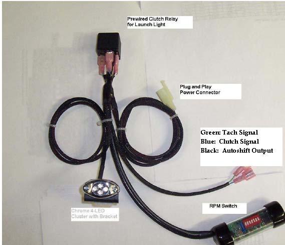
1 Boost by Smith s Dual Purpose Shift Light Greg Smith SMITHABUSA greg@boostbysmith.com
2
3 ****WARNING**** This Dual-Purpose Launch-Shift Light can cause damage to both you and your motorcycle if not used properly. There are few things to keep in mind and suggestions for this product: The auto-shift function is active whenever the shift light illuminates. The launch light activating will not trigger the auto-shift, but the shift light will trigger the auto-shift output. When you make changes to your Shift RPM Setpoint, the settings are then flashed back across the shift light. When this happens be sure to have your toggle switch off, and your air shifter kill box and bottle pressure deactivated and turned off. If you fail to do this and change your shift RPM setting this could result in the bike trying to shift the transmission multiple times rapidly while sitting still. THIS WILL CAUSE DAMAGE TO YOUR TRANSMISSION!!! For this reason, see the next item below. Run the auto-shift wire (Black wire with female spade connector) through a toggle switch before hooking it to your kill box triiger input and air solenoid ground wires. This will allow you to manually turn auto-shift on or off. When performing your burnout, it would be advised to turn the auto-shift off in case you over rev during burnout, you don t want the bike shifting into the next gear during your burnout. Never rev the engine to redline in neutral, if the shift light activates and your toggle switch is on it will try to shift most likely resulting in transmission damage as well as possibly throwing you off the bike. It is my suggestion to leave your current shift button hooked up (horn button most commonly used) in case the bike ever starts to wheelie and you need to short shift. If you connect the horn signal to the same wire as auto-shift (after the toggle switch) you will be able to hit the button and shift the bike manually earlier than what auto-shift is set for. If there are any questions or concerns on the operation or safety of this product feel free to contact me at the phone number and address listed on the cover page. ****WARNING****
4 Thanks for your purchase of the BoostBySmith shift light. As a special note, I have already programmed your light for you for the following setpoints: Number of cylinders: 2 (this is needed for Suzuki when using the tach signal wire yellow w/blue tracer Wire) Launch RPM: 5000 RPM Launch Window: 500 RPM (launch light will come on from RPM) Shift RPM: 10,600 RPM (keep in mind your tach will read about 11,200 11,300 at this Setting as the stock Suzuki tach s read very high. The biggest mistakes people make when hooking up my shift light s are: Hooking into the wrong yellow with blue wire tach signal (its NOT the one at the large yellow connector over the left ram air tube, that s +12V with high beam on). Its in sealed up harness where left ram air tube meets the frame. Setting number of cylinders wrong. Using the tach signal (yellow with blue tracer) you should be set to 2 cylinder mode. If you are using #1 coil ground you should be using coil on plug mode. Not understanding that the stock reads very high, so people usually go out and look at tach for exact setting and shift light doesn t come on, you aren t revving the bike high enough due to the inaccurate tach, set the light lower, or rev the bike further out. Hayabusa s read rpm fast at redline. Some devices such as Wego datalogger being on the same tach wire as shift light can cause issues, move one of the 2 devices to #1 coil ground and reprogram number of cylinders to coil on plug if shift light or 1 cylinder for datalogger to alleviate this. For autoshift output: I have recently started adding a toggle switch to the shift light assembly (only if you have added autoshift output, this will allow you to enable / disable autoshift output. The short black wire with female spade connector is the autoshift output wire, this should be connected to the blue wire on a MPS kill box, white wire on a Cycle tek kill box, or on the white wire of a cycle tek ECU air shifter harness.


5 This photo shows the optional toggle switch if you purchase autoshift output ON and OFF positions:
.")
6 The following photo s show the location of the Euro connector, some people have trouble finding these, unless you cut it off the bike, its there on the headlight harness next to right turn signal (gen 1 hayabusa, and the small lights above headlight are plugged into it on gen 2 hayabusa s). On gen 2 hayabusas you have to plug my shift light inline on the small light above headlight.
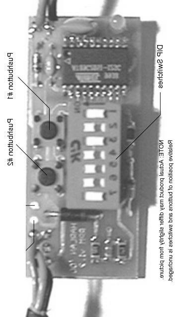
7 Launch Light Setup Instructions To set # of cylinders: Set dip switch setting to desired # of cylinders, then hold down push buttons 1 & 2, then power the RPM switch up by turning the key on, continue to hold the buttons until the launch light flashes rapidly, the setting will be flashed back to you for verification. Note: Suzuki Hayabusa should be set to 2 cylinder mode for proper RPM settings. To set Launch RPM: Set dip switch setting to desired launch RPM, then hold down button 2 until it flashes rapidly, the setting will be flashed back to you for verification. This value is adjustable from 3,000 15,700 RPM in 100 RPM increments. In order to see the launch light setting, you must pull the clutch lever in the entire time the settings are being flashed back. Zero is display as two very quick flashes. To set Launch Upper Window: Set dip switch setting to desired upper launch window, then hold down buttons 1 & 2 until it flashes rapidly, the setting will be flashed back to you for verification. This value is adjustable from 100-3,000 RPM and doesn t need to be changed when changing the actual launch RPM. For example, once you set the launch window to say 500 RPM, no matter what you set the launch RPM to, the upper window will always be 500 RPM higher than the launch RPM. Setting this value to 0 will allow the launch light to stay illuminated anytime you are over the rpm set point (same as shift light). In order to see the launch window setting, you must pull the clutch lever in the entire time the settings are being displayed. Zero is displayed as two very quick flashes. To set Shift RPM: Set dip switch setting to desired Shift RPM, then hold down button 1 until it flashes rapidly, the setting will be flashed back to you for verification. This value is adjustable from 3,000 15,700 RPM in 100 RPM increments. Note: Zero is displayed as two very quick flashes of the light. 10,600 for example would be displayed as: 1...pause...two quick flashes for zero...pause Wiring: The clutch signal wire must be tapped into if you have purchased a Launch Light. On the Hayabusa, the switched clutch signal wire is on the left hand side of the bike in the taped up harness as well as visible at the large yellow connector. The wire is black with a yellow tracer. Align the wire in the yellow scotch lock connector and press down firmly. The tach signal wire must be tapped into if you have purchased a Shift Light. On the Hayabusa, the tach signal wire is on the left hand side of the bike in the taped up harness. The wire is yellow with a blue tracer. DO NOT mistake the other yellow wire with blue tracer that is visible at the large yellow connector, this is NOT the correct wire. Again, use the red scotch lock connector included and make sure it seats firmly. The Auto-Shift wire (black wire with female spade connector) should be ran through a toggle switch, then to your kill box triiger input wire (should be inline with horn signal wire.)

8 TACH SIGNAL ILLUSTRATION CRIMP THE RED SCOTCH-LOCK CONNECTOR ON THE YELLOW WIRE WITH BLUE TRACER INSIDE THIS HARNESS. NOW CONNECT THE GREEN LEAD FROM THE SHIFT LIGHT HARNESS TO THE RED SCOTCH LOCK CONNECTOR

9 CLUTCH SIGNAL ILLUSTRATION CRIMP THE RED SCOTCH-LOCK CONNECTOR ON THE BLACK WIRE WITH YELLOW TRACER INSIDE THIS HARNESS. NOW CONNECT THE BLUE LEAD FROM THE SHIFT LIGHT HARNESS TO THE RED SCOTCH LOCK CONNECTOR

10 POWER AND GROUND CONNECTOR (INSIDE THE NOSE NEAR THE RIGHT TURN SIGNAL, PLUG INTO THE 2 PIN CONNECTOR.


11 RPM SWITCH PLACEMENT CLUTCH RELAY PLACEMENT
12 SWITCH POSITIONS SWITCH POSITIONS RPM RPM OFF OFF OFF OFF OFF OFF OFF 9400 OFF OFF OFF OFF OFF OFF ON 3100 ON OFF OFF OFF OFF OFF OFF 9500 ON OFF OFF OFF OFF OFF ON 3200 OFF ON OFF OFF OFF OFF OFF 9600 OFF ON OFF OFF OFF OFF ON 3300 ON ON OFF OFF OFF OFF OFF 9700 ON ON OFF OFF OFF OFF ON 3400 OFF OFF ON OFF OFF OFF OFF 9800 OFF OFF ON OFF OFF OFF ON 3500 ON OFF ON OFF OFF OFF OFF 9900 ON OFF ON OFF OFF OFF ON 3600 OFF ON ON OFF OFF OFF OFF OFF ON ON OFF OFF OFF ON 3700 ON ON ON OFF OFF OFF OFF ON ON ON OFF OFF OFF ON 3800 OFF OFF OFF ON OFF OFF OFF OFF OFF OFF ON OFF OFF ON 3900 ON OFF OFF ON OFF OFF OFF ON OFF OFF ON OFF OFF ON 4000 OFF ON OFF ON OFF OFF OFF OFF ON OFF ON OFF OFF ON 4100 ON ON OFF ON OFF OFF OFF ON ON OFF ON OFF OFF ON 4200 OFF OFF ON ON OFF OFF OFF OFF OFF ON ON OFF OFF ON 4300 ON OFF ON ON OFF OFF OFF ON OFF ON ON OFF OFF ON 4400 OFF ON ON ON OFF OFF OFF OFF ON ON ON OFF OFF ON 4500 ON ON ON ON OFF OFF OFF ON ON ON ON OFF OFF ON 4600 OFF OFF OFF OFF ON OFF OFF OFF OFF OFF OFF ON OFF ON 4700 ON OFF OFF OFF ON OFF OFF ON OFF OFF OFF ON OFF ON 4800 OFF ON OFF OFF ON OFF OFF OFF ON OFF OFF ON OFF ON 4900 ON ON OFF OFF ON OFF OFF ON ON OFF OFF ON OFF ON 5000 OFF OFF ON OFF ON OFF OFF OFF OFF ON OFF ON OFF ON 5100 ON OFF ON OFF ON OFF OFF ON OFF ON OFF ON OFF ON 5200 OFF ON ON OFF ON OFF OFF OFF ON ON OFF ON OFF ON 5300 ON ON ON OFF ON OFF OFF ON ON ON OFF ON OFF ON 5400 OFF OFF OFF ON ON OFF OFF OFF OFF OFF ON ON OFF ON 5500 ON OFF OFF ON ON OFF OFF ON OFF OFF ON ON OFF ON 5600 OFF ON OFF ON ON OFF OFF OFF ON OFF ON ON OFF ON 5700 ON ON OFF ON ON OFF OFF ON ON OFF ON ON OFF ON 5800 OFF OFF ON ON ON OFF OFF OFF OFF ON ON ON OFF ON 5900 ON OFF ON ON ON OFF OFF ON OFF ON ON ON OFF ON 6000 OFF ON ON ON ON OFF OFF OFF ON ON ON ON OFF ON 6100 ON ON ON ON ON OFF OFF ON ON ON ON ON OFF ON 6200 OFF OFF OFF OFF OFF ON OFF OFF OFF OFF OFF OFF ON ON 6300 ON OFF OFF OFF OFF ON OFF ON OFF OFF OFF OFF ON ON 6400 OFF ON OFF OFF OFF ON OFF OFF ON OFF OFF OFF ON ON 6500 ON ON OFF OFF OFF ON OFF ON ON OFF OFF OFF ON ON 6600 OFF OFF ON OFF OFF ON OFF OFF OFF ON OFF OFF ON ON 6700 ON OFF ON OFF OFF ON OFF ON OFF ON OFF OFF ON ON 6800 OFF ON ON OFF OFF ON OFF OFF ON ON OFF OFF ON ON 6900 ON ON ON OFF OFF ON OFF ON ON ON OFF OFF ON ON 7000 OFF OFF OFF ON OFF ON OFF OFF OFF OFF ON OFF ON ON 7100 ON OFF OFF ON OFF ON OFF ON OFF OFF ON OFF ON ON 7200 OFF ON OFF ON OFF ON OFF OFF ON OFF ON OFF ON ON 7300 ON ON OFF ON OFF ON OFF ON ON OFF ON OFF ON ON 7400 OFF OFF ON ON OFF ON OFF OFF OFF ON ON OFF ON ON 7500 ON OFF ON ON OFF ON OFF ON OFF ON ON OFF ON ON 7600 OFF ON ON ON OFF ON OFF OFF ON ON ON OFF ON ON 7700 ON ON ON ON OFF ON OFF ON ON ON ON OFF ON ON 7800 OFF OFF OFF OFF ON ON OFF OFF OFF OFF OFF ON ON ON 7900 ON OFF OFF OFF ON ON OFF ON OFF OFF OFF ON ON ON 8000 OFF ON OFF OFF ON ON OFF OFF ON OFF OFF ON ON ON 8100 ON ON OFF OFF ON ON OFF ON ON OFF OFF ON ON ON 8200 OFF OFF ON OFF ON ON OFF OFF OFF ON OFF ON ON ON 8300 ON OFF ON OFF ON ON OFF ON OFF ON OFF ON ON ON 8400 OFF ON ON OFF ON ON OFF OFF ON ON OFF ON ON ON 8500 ON ON ON OFF ON ON OFF ON ON ON OFF ON ON ON 8600 OFF OFF OFF ON ON ON OFF OFF OFF OFF ON ON ON ON 8700 ON OFF OFF ON ON ON OFF ON OFF OFF ON ON ON ON 8800 OFF ON OFF ON ON ON OFF OFF ON OFF ON ON ON ON 8900 ON ON OFF ON ON ON OFF ON ON OFF ON ON ON ON 9000 OFF OFF ON ON ON ON OFF OFF OFF ON ON ON ON ON 9100 ON OFF ON ON ON ON OFF ON OFF ON ON ON ON ON 9200 OFF ON ON ON ON ON OFF OFF ON ON ON ON ON ON 9300 ON ON ON ON ON ON OFF ON ON ON ON ON ON ON
13 LAUNCH WINDOW SWITCH POSITIONS RPM OFF OFF OFF OFF OFF OFF OFF 100 ON OFF OFF OFF OFF OFF OFF 200 OFF ON OFF OFF OFF OFF OFF 300 ON ON OFF OFF OFF OFF OFF 400 OFF OFF ON OFF OFF OFF OFF 500 ON OFF ON OFF OFF OFF OFF 600 OFF ON ON OFF OFF OFF OFF 700 ON ON ON OFF OFF OFF OFF 800 OFF OFF OFF ON OFF OFF OFF 900 ON OFF OFF ON OFF OFF OFF 1000 OFF ON OFF ON OFF OFF OFF 1100 ON ON OFF ON OFF OFF OFF 1200 OFF OFF ON ON OFF OFF OFF 1300 ON OFF ON ON OFF OFF OFF 1400 OFF ON ON ON OFF OFF OFF 1500 ON ON ON ON OFF OFF OFF 1600 OFF OFF OFF OFF ON OFF OFF 1700 ON OFF OFF OFF ON OFF OFF 1800 OFF ON OFF OFF ON OFF OFF 1900 ON ON OFF OFF ON OFF OFF 2000 OFF OFF ON OFF ON OFF OFF 2100 ON OFF ON OFF ON OFF OFF 2200 OFF ON ON OFF ON OFF OFF 2300 ON ON ON OFF ON OFF OFF 2400 OFF OFF OFF ON ON OFF OFF 2500 ON OFF OFF ON ON OFF OFF 2600 OFF ON OFF ON ON OFF OFF 2700 ON ON OFF ON ON OFF OFF 2800 OFF OFF ON ON ON OFF OFF 2900 ON OFF ON ON ON OFF OFF 3000 OFF ON ON ON ON OFF OFF
14 SWITCH POSITIONS # Cylinders ON OFF OFF OFF OFF OFF OFF 4 OFF ON OFF OFF OFF OFF OFF 6 OFF OFF ON OFF OFF OFF OFF 8 OFF OFF OFF ON OFF OFF OFF Coil Per Plug OFF OFF OFF OFF ON OFF OFF NOTE: Suzuki Hayabusa should be set to 2 Cylinder Mode
15
Quick-Kill Installation Manual V1.0 (Universal Motorcycle Application)
") Quick-Kill Installation Manual V1.0 (Universal Motorcycle Application) THIS INSTALLATION MANUAL IS FOR UNIVERSAL FUEL INJECTED MOTORCYCLE APPLICATIONS (NON PLUG AND PLAY), WITH OR WITHOUT A GEAR POSITION
Quick-Kill Installation Manual V1.0 (Universal Motorcycle Application) THIS INSTALLATION MANUAL IS FOR UNIVERSAL FUEL INJECTED MOTORCYCLE APPLICATIONS (NON PLUG AND PLAY), WITH OR WITHOUT A GEAR POSITION
Innovative Racing Electronics
 MPS Fast FI Mixture Control Installation Instructions The MPS Fast FI Mixture Control P/N 1-0337 is a simple means to adjust the fuel curves on your fuel-injected motorcycle. This allows for tuning after
BMW 2002 M42 Swap Notes-THIS IS NOT FINISHED
 BMW 2002 M42 Swap Notes-THIS IS NOT FINISHED This document is to help those that want to install an m42 into a BMW 2002. It is based around an e30 engine, trans, and wiring. You can use the e36 block/head/wiring
Thank you for choosing the Techlusion Electronic Jet Kit, the TFI. The TFI is usable for sequential fuel injection 2 cylinder Suzuki motorcycles **.
 Rev 1.1.1 2055ST TFI TFI Patent Numbers: 7,000,599 & 7,124,742 TFI Instructions Suzuki Thank you for choosing the Techlusion Electronic Jet Kit, the TFI. The TFI is usable for sequential fuel injection
NEXTUP TERMINAL STRIP CONTROLLER INSTALLATION MANUAL - VER 1.5
 CONTENTS INTRODUCTION 1 STEP ONE QUICKSHIFTER Power and Ground 3 STEP TWO QUICKSHIFTER Wiring and Final Connections 4 STEP ONE AIR SHIFTER Power and Ground 6 STEP TWO AIR SHIFTER Wiring and Final Connections
Torque Convertor Control System
 22 September 2015 PN#1030395 TorqLoc (I-00208) 1 BD TorqLoc Torque Convertor Control System Part# 1030395 Installation Manual for the following applications: BD Brakes for Dodge, Ford and Chevrolet Pac
HID INSTALLATION ON RST1000 Futura
 HID INSTALLATION ON RST1000 Futura Disclaimer: This is a full description of what I have done to my motorcycle. I am in no way suggesting you do as I have done by following these instructions. I have not
USER MANUAL AND INSTALLATION GUIDE ENGINE RPM AND NOS SHIFT COUNTER NOS DELAY TIME IN SECONDS NOS START PERCENT NOS FINAL PERCENT
 SCHNITZ MOTORSPORTS DSC-9PS "PRO-STREET" IGNITION CONTROLLER USER MANUAL AND INSTALLATION GUIDE SHIFT LIGHT POSITIVE PAGE 2 SHIFT LIGHT GROUND PAGE 2 NOS SOLENOID GROUND 1GA ORANGE, FUEL SOLENOID GROUND
Torque Convertor Control System
 1 BD AutoLoc Torque Convertor Control System Part# 1030390 Installation Manual for the following applications: BD Brakes for Dodge, Ford and Chevrolet Pac Brake for Dodge & Ford Jacobs E-Brake for 1994-98
P/N 646 MODE L LOW RPM H HIGH RPM C CYLINDER SELECT P/N 646 H HIGH RPM C CYLINDER SELECT WINDOW RPM SWITCH L LOW RPM VALUE MODE MODE DOWN RED GREEN
 INSTALLATION INSTRUCTIONS FORM 1008 (REV A) 01/02 WINDOW RPM ACTIVATED SWITCH PART NO 646 Parts Included in this kit: 1 RPM Activated Switch Part No 646 1 U shaped crimp-on wire terminal 1 #6 x 1/4" sheet
Replacing stock Ducati relays with solid state type
 Replacing stock Ducati 748-916-996 relays with solid state type Ducati stock relays are basically just the ordinary automotive type in a waterproof housing. They suffer from wear & tear as they contain
Contacts The moveable contact, which is the one affected by the armature is sometimes referred to as the hinge contact.
 Relays & Wiring 101 Basically, a relay is an electrically operated, remotely controlled switch. A simple electromagnetic relay is an adaptation of an electromagnet. It consists of a coil of wire surrounding
MSD 7AL-3, Ignition Control PN 7230
 MSD 7AL-3, Ignition Control PN 7230 Important: Read the instructions before attempting the installation. Parts Included: 1-7AL-3, PN 7230 1 - Parts bag (wires and connectors) 4 - RPM Modules 3000, 7000,
Aftermarket Interface Module
 An ISO 9001:2008 Registered Company Aftermarket Interface Module (2015-2018 Ford Transit) AIM514-B High Side Solenoid type Coolant Valve Control AIM515-B Motor Reversing type Coolant Valve Control Introduction
SCHNITZ. Racing SCB-PPI Programmable Power Interrupt Installation and Operation Instructions
 SCB-PPI Programmable Power Interrupt Installation and Operation Instructions Description The SCB-PPI Programmable Power Interrupt is a fully digital and programmable unit used to interrupt the coil charge
JK ATLAS CONTROL MODULE (ATLAS UNITS BUILT BEFORE 7/2014) KIT CONSISTS OF:
 KIT CONSISTS OF:") KIT CONSISTS OF: No. Qty Part No. Description 1. 1 42R800 CONTROL MODULE KIT KIT INCLUDES 2 8-32 SOCKET HEAD CAP SCREWS 2 8-32 NYLON LOCK NUTS 5 1/4"x1" HEAT SHRINK 1 3 WIRE DELPHI CONNECTOR 1 2 WIRE DELPHI
KIT CONSISTS OF: No. Qty Part No. Description 1. 1 42R800 CONTROL MODULE KIT KIT INCLUDES 2 8-32 SOCKET HEAD CAP SCREWS 2 8-32 NYLON LOCK NUTS 5 1/4"x1" HEAT SHRINK 1 3 WIRE DELPHI CONNECTOR 1 2 WIRE DELPHI
SCHNITZ MOTORSPORTS USER MANUAL AND INSTALLATION GUIDE PRO-MOD BATTERY VOLTS DIAGNOSTICS NOS PULSE FREQUENCY NOS DELAY TIME IN SECONDS
 SCHNITZ MOTORSPORTS DSC-CS "PRO-MOD" IGNITION CONTROLLER USER MANUAL AND INSTALLATION GUIDE COIL, (OPTIONAL) GA YELLOW, COIL, NEGATIVE GA WHITE, GA BLACK, SHIFT LIGHT +V OUTPUT PAGE 0 NOS ACTIVATION INPUT
Rostra Electronic Cruise Control Install On a Stratoliner or Roadliner
 Rostra Electronic Cruise Control Install On a Stratoliner or Roadliner MATERIALS LIST: 1 - Rostra Part # 250-1223 (www.brandondist.com/products/cruise1223.htm) 1 - Signal Splitter part # 250-4369 1 - Engagement
PLEASE READ ALL DIRECTIONS BEFORE STARTING INSTALLATION
 2002-2007 Suzuki Hayabusa Installation Instructions PARTS LIST 1 Ignition Module 1 Installation Guide 2 Velcro strips 1 Alcohol swab 1 CAN link cable 1 USB cable 1 Posi-tap THE VEHICLE S IGNITION MUST
Disconnect the negative battery cable!
 Understanding Mod-3 on a C90 With Wiring Diagrams By DrJones18LC I do not have a C90 at my disposal (or audio/video equipment for that matter) so I can't make a live step by step how-to on doing Mod-3.
TOURING Models
 P/N FI-1252HPST Patent Numbers: 7,000,599 & 7,124,742 Electronic Jet Kit Instructions Thank you for choosing the Techlusion Electronic Jet Kit, the TFI. This TFI model is ONLY usable for the following
Indian Speedometer and Body Control Module Service Tool Users Guide
 Indian Speedometer and Body Control Module Service Tool Users Guide Installing speedometer software to your computer 1. Go to the Indian Motorcycle Website: WWW. Indianmotorcycle.com 2. Log in to Service
USER MANUAL AND INSTALLATION GUIDE TIMER DELAY IN SECONDS SHIFT STYLE & SHIFT COUNTER TIMER DURATION NOS DELAY TIME IN SECONDS NOS START PERCENT
 SCHNITZ MOTORSPORTS DSC-TG0- "TOP-GAS " IGNITION CONTROLLER USER MANUAL AND INSTALLATION GUIDE COIL, (OPTIONAL) GA YELLOW, PAGE COIL, NEGATIVE GA WHITE, PAGE SHIFT LIGHT GROUND 0GA BROWN, PAGE 0 SHIFT
RSR Twin Cam Bonneville Gear Indicator
 RSR Twin Cam Bonneville Gear Indicator First step is to mount the gauge where you can easily see it in normal vehicle operation. A gear position indicator is meant to be used, not just because it is a
WARNING! USE ONLY IN RACE OR OTHER CLOSED COURSE APPLICATIONS AND NEVER ON PUBLIC ROADS
 2010-2013 Kawasaki Z1000 2011-2013 Kawasaki Ninja 1000 Z-Fi TC / Z-FI QS INSTALLATION INSTRUCTIONS P/N s S490S, S490R, T490S, T490R WARNING! USE ONLY IN RACE OR OTHER CLOSED COURSE APPLICATIONS AND NEVER
6500DC Dual Motor Wireless Controller Kits
 6500DC Dual Motor Wireless Controller Kits READ ALL DIRECTIONS FIRST BEFORE PROCEEDING NOTE: SEE THE QUICK PROGRAM INSTRUCTIONS BEFORE OPERATING THE FIRST TIME. DO NOT REMOVE THE TRANSMITTER BATTERY Please
ELITE 600
 www.racedigitaldelay.com ELITE 600 Instruction Manual - 1 - The ELITE 600 From DIGITAL DELAY 2036 Fillmore Street Davenport Iowa 52804 563-324-1046 www.racedigitaldelay.com Congratulations on your purchase
ECT Display Driver Installation for AP2 Module
 ECT Display Driver Installation for AP2 Module Overview The ECT Display Driver is a small module with a removable wire harness that mounts behind the driver's foot well cover. All wiring connections are
Automotive Application ET01 Software Revision A 12/06
 Automotive Application ET01 Software Revision A 12/06 INTRODUCTION... 2 FUNCTIONAL DESCRIPTION... 3 INSTALLATION... 4 COMPONENT PLACEMENT... 4 PLUMBING AND WIRING... 5 MSBC OPERATION (ET-01)... 14 TIMED
Electronic Jet Kit Instructions
 Rev 1.0.3 FI-1040ST Electronic Jet Kit Instructions Thank you for choosing the Techlusion Electronic Jet Kit, the TFI. The TFI is usable for both early and late model fuel injected Harley Davidson s. This
MCL-3000 SERIES AIR PRESSURE PART# MCL-3K-A
 MCL-3000 SERIES AIR PRESSURE PART# MCL-3K-A Thank you for purchasing the Dakota Digital MCL-3K-A gauge for your Harley Davidson Touring bike. This gauge is designed to be a direct, plug in replacement
Installation Tips Crimestopper/ProStart Remote Start system + PLJX + DLRM + SPDT (for GM vehicles) T0760 v1.1 updated 2/5/14
 T0760 v1.1 updated 2/5/14") Installation Tips Crimestopper/ProStart Remote Start system + PLJX + DLRM + SPDT (for GM vehicles) T0760 v1.1 updated 2/5/14 Thank you for purchasing your remote start from MyPushcart.com - an industry
Installation Tips Crimestopper/ProStart Remote Start system + PLJX + DLRM + SPDT (for GM vehicles) T0760 v1.1 updated 2/5/14 Thank you for purchasing your remote start from MyPushcart.com - an industry
Fabricating and Installing Headlight Relays. Mike Graham
 Fabricating and Installing Headlight Relays Mike Graham For some time I had been reading about the benefits of installing headlight relays. As I understand it, there are two principal benefits: the load
Product Overview. Shift light turns on when RPM is above programmed shift point. Stage 2 activation light turns on when Stage 2 is active.
 These instructions will guide you through the setup, installation, and use of the Nitrous Outlet WinMax Window Switch. If you have any questions about the WinMax, please call our Tech Help Line at (254)
WARNING: the engine does not come with oil in it. Please fill the oil before starting. The 200cc hardknock requires 9/10 of a quart of oil.
 WARNING: the engine does not come with oil in it. Please fill the oil before starting. The 200cc hardknock requires 9/10 of a quart of oil. Things needed for assembly. -2 tubes of blue loc-tite. I don
Asynchronous Restriking CDI 2 channel
 Asynchronous Restriking CDI 2 channel Parts List ARC-2 module Decals Power Cable Fuse Specifications Operating Voltage: 8-20V Operating Current: Max Operating RPM: Ambient Temp range: Ignition inputs:
BULLET & MINI-BULLET TACHOMETERS INSTALLATION GUIDE - Please see appropriate section for your specific application
 Revision: 17.7-04/12/2012 Install Time: 30 to 90 Minutes BA-757x-xx Page: 1 Go slowly and follow instructions carefully. The installation is very easy if the wire color destinations are followed. INCLUDED
Lingenfelter Launch Control Module
 Installation Instructions For Lingenfelter Launch Control Module Adjustable Launch Controller & RPM Limiter For GM LSx Series Engines NOW With Timing Retard Mode PN: L4615297 1557 Winchester Road Decatur,
Installation Instructions for Lingenfelter Shift Light Controller with green LED
 Installation Instructions for Lingenfelter Shift Light Controller with green LED PN: L460080000 1557 Winchester Road Decatur, Indiana 46733 260 724 2552 phone 260 724 8761 fax www.lingenfelter.com Parts
INSTALLATION INSTRUCTIONS FOR THE TOMAHAWK ELECTRIC REVERSE
 INSTALLATION INSTRUCTIONS FOR THE TOMAHAWK ELECTRIC REVERSE LAST UPDATED: April 2018 Thank you for choosing the Motor Trike Electric Reverse. We ask that you read the directions before you start and follow
ELITE 625 With Dial Display Control
 www.racedigitaldelay.com ELITE 625 With Dial Display Control Instruction Manual - 1 - The ELITE 625 From DIGITAL DELAY 2036 Fillmore Street Davenport Iowa 52804 563-324-1046 www.racedigitaldelay.com Congratulations
Installation. Tools needed: 8mm and 10mm spanner, ( Hacksaw, 5 mm drill and m6 tap). Pliers to crimp connector pins.
. Pliers to crimp connector pins.") GP SG MotoGP Technology Fantastic Precision Fully Computerized Amazing Performance Proven Championship Winner Moto 3 World Championship 2015 Honda HRC with Danny Kent. Nordic BoTT 2010, 2011, 2012, 2014,
GP SG MotoGP Technology Fantastic Precision Fully Computerized Amazing Performance Proven Championship Winner Moto 3 World Championship 2015 Honda HRC with Danny Kent. Nordic BoTT 2010, 2011, 2012, 2014,
jegs.com
 Contents Wiring Harness w/ Fuse Panel Installation Instructions Turn Signal Plug w/ Terminals 2 Headlight Plugs 3/4 Grommet 10 ¼ Terminals 4 Ring Terminals 10 Wire Ties Fusible Link 2 Screws & Nuts 2 Plastic
The RPM module will remain in Normal mode by default. It will also return to this mode after settings have been recalled or changed
 Shiftlight Operating Instructions: Setting up your shiftlight: The RPM module requires you to set the turn-on RPM and the number of cylinders. Once these two pieces of information are set, they will not
An ISO 9001:2008 Registered Company
 Overview An ISO 9001:2008 Registered Company AFIS422VSX-B Advanced Fast Idle System - Transit Application 2009-2017 Ford E-Series, all engines 2009-2010 Ford F-250 - F-550, all engines 2014-2018 Ford F53/F59,
Installation Tips for your Crimestopper/ProStart Remote Start system (for GM vehicles) v1.01 updated 2/27/2012
 v1.01 updated 2/27/2012") Installation Tips for your Crimestopper/ProStart Remote Start system (for GM vehicles) v1.01 updated 2/27/2012 Thank you for purchasing your remote start from MyPushcart.com - an industry leader in providing
Installation Tips for your Crimestopper/ProStart Remote Start system (for GM vehicles) v1.01 updated 2/27/2012 Thank you for purchasing your remote start from MyPushcart.com - an industry leader in providing
INTERNATIONAL 3200 AND Freightliner MB
 An ISO 9001:2000 Registered Company INTERNATIONAL 3200 AND Freightliner MB55 2002-2008 Intelligent Lift Interlock System (ILIS701-D) - Installation Instructions International & MB45/55 w/allison 2000 and
Retro it Steering Column
 Retro it Steering Column INSTALLATION INSTRUCTIONS for 1976-86 CJ5 & CJ7 FOR PART NUMBER S: 1520800010, 1520800020, 1520800051, 1526800010, 1526800020, 1526800051 S I NCE 1986 Instruction # 8000000010
Allison Lockup Controller
 19 February 2018 1031311/1031312/1031313 Allison Transmission Lockup and Pressure Module (I-00413) 1 Allison Lockup Controller Transmission Lockup and Pressure Controller 1031311 1031312 1031313 2001-2010
Installation Instructions Jeep CJ-7
 Retrofit Steering Column Installation Instructions 1976-86 Jeep CJ-7 For Part # s 1520800010, 152800020, 1520800051 www.ididitinc.com 610 S. Maumee St., Tecumseh, MI 49286 (517) 424-0577 (517) 424-7293
PLEASE READ ALL DIRECTIONS BEFORE STARTING INSTALLATION
 2008-2016 Honda CB1000R Installation Instructions PARTS LIST 1 Ignition Module 1 Installation Guide 2 Velcro strips 1 Alcohol swab 1 CAN link cable 1 USB cable 1 Posi-tap THE VEHICLE S IGNITION MUST BE
BMW S1000RR Z-Fi QS / Z-Fi TC Installation Instructions P/N S541S, S541R, T541S, T541R
 2009-2013 BMW S1000RR Z-Fi QS / Z-Fi TC Installation Instructions P/N S541S, S541R, T541S, T541R WARNING! USE ONLY IN RACE OR OTHER CLOSED COURSE APPLICATIONS AND NEVER ON PUBLIC ROADS Z-Fi products do
Kawasaki Vulcan 1500 Classic
 Floppy Disc Request Form If you do not have a CD-Rom drive and would like to receive the program and the alternate maps for your model on a 3 1/2 floppy disc, please fax this form to Dynojet at 1-702-399-1431
Installation Tips for your Crimestopper/ProStart Remote Start system (add-on for GM vehicles) v1.02 updated 1/16/2013
 v1.02 updated 1/16/2013") Installation Tips for your Crimestopper/ProStart Remote Start system (add-on for GM vehicles) v1.02 updated 1/16/2013 Thank you for purchasing your remote start from MyPushcart.com - an industry leader
Installation Tips for your Crimestopper/ProStart Remote Start system (add-on for GM vehicles) v1.02 updated 1/16/2013 Thank you for purchasing your remote start from MyPushcart.com - an industry leader
PERTRONIX DIGITAL HP INSTALLATION INSTRUCTIONS
 PERTRONIX DIGITAL HP INSTALLATION INSTRUCTIONS TABLE OF CONTENTS Specifications... 4 General Information... 5 Coil Compatibility... 6 Mounting the Digital HP... 7 Wiring... 8 User Interface... 12 Programming...
ODYR-25-1 & SLX-25-1 rev. A VACUUM/BOOST PRESSURE, TEMP, and EGT GAUGE
 ODYR-25-1 & SLX-25-1 rev. A VACUUM/BOOST PRESSURE, TEMP, and EGT GAUGE SENSOR CONNECTION: The vac./boost sensor has 1/8 NPT on the end which can be treaded into the intake track, or into a pipe adapter
Instruction Manual. What s In The Box? CANsmart Controller DNL.WHS BMW K1600 Series. Kit Contents DENALIELECTRONICS.COM
 Instruction Manual Instruction Rev0 Thank you for choosing DENALI We know you would rather be riding your bike than wrenching on it, so we go the extra mile to make sure our instructions are clear and
ATTENTION. Custom Dynamics Smart Triple Play Installation Instructions. Package Contents: - Smart Triple Play Module (1) - Instructions
 - Instructions") Custom Dynamics Smart Triple Play Installation Instructions We thank you for purchasing the Custom Dynamics Smart Triple Play. Our products utilize the latest technology and high quality components to
Custom Dynamics Smart Triple Play Installation Instructions We thank you for purchasing the Custom Dynamics Smart Triple Play. Our products utilize the latest technology and high quality components to
Our goal is to make the install a breeze. Please read the entire guide before beginning.
 www.airkewld.com Page 1 of 6 IRS Axle Kit Install IRS Axle Kit Install Our goal is to make the install a breeze. Please read the entire guide before beginning. KITS SHOULD INCLUDE 2 - Control-arm mounting
CLASSIC UPDATE WIRING KIT
 by Randy Irwin 1955-57 CLASSIC UPDATE WIRING KIT Randy Irwin - Technical Writer Randy has been involved in the Chevy parts business for over 25 years. He is a wizard at creating, making and modifying custom
INSTALLATION INSTRUCTIONS 5" SINGLE CHANNEL ULTIMATE TACH
 Instr. No. 2650-887D INSTALLATION INSTRUCTIONS 5" SINGLE CHANNEL ULTIMATE TACH IMPORTANT WEAR SAFETY GLASSES 5 4 6 COPYRIGHT PATENT PENDING 3 7 8 PLAYBACK 9 2 0 1 AUTO METER PRODUCTS, INC. SYCAMORE, IL
ESS INSTALL. The donor car /6 Cosmos Black/Sand UUC Short Shifter Brembo cross drilled rotors Phillips Nav System 16:9
 ESS INSTALL The donor car.. 1997 540/6 Cosmos Black/Sand UUC Short Shifter Brembo cross drilled rotors Phillips Nav System 16:9 The install went in several stages. Disconnect the battery Stage 1 Remove
HP10134 & HP10135 KITS BASIC SIMULTANEOUS AIR SPRING ACTIVATION KIT
 HP10134 & HP10135 KITS BASIC SIMULTANEOUS AIR SPRING ACTIVATION KIT Thank you and congratulations on the purchase of a Pacbrake simultaneous air spring activation kit. This kit was designed to add in-cab
CONTROL BOX. Wiring the control box into the vehicle. +12V
 CONTROL BOX Once the display panel is in place, mount the control box within the connecting cable's distance (approximately 3 feet) and secure to the underside of the dashboard. This case does not have
WOT Box Installation Instructions VW / Audi
 Connector Pinout Pin Color AWG Name WOT Box Installation Instructions VW / Audi Description 1 Yellow 18 RPM Connect to Fuel Injector Drive Signal or Ignition Control Signal (varies by car model) 2 Black
WARNING! USE ONLY IN RACE OR OTHER CLOSED COURSE APPLICATIONS AND NEVER ON PUBLIC ROADS
 2010-2013 Ducati Streetfighter Z-Fi TC / Z-FI QS INSTALLATION INSTRUCTIONS P/N s S190S, S190R, T190S, T190R WARNING! USE ONLY IN RACE OR OTHER CLOSED COURSE APPLICATIONS AND NEVER ON PUBLIC ROADS Z-Fi
QUICK INSTALLATION GUIDE
 MANUAL/AUTOMATIC T R A N S M I S S I O N 2 - B U T T O N R E M O T E S T A R T E R W I T H V I R T U A L T A C H S Y S T E M ( A S P R G - 1 0 0 0 C O M P A T I B L E ) QUICK INSTALLATION GUIDE Manual
X-Charge Fitting Instructions
 X-Eng is a division of Foundry 4x4 Limited The Old Bakery, Rear of Vale Terrace, Tredegar, Gwent. NP22 4HT X-Charge Fitting Instructions Thank you for choosing to buy an X-Charge! Vehicle newer than 1995
Introduction. Open Loop vs. Closed Loop. The Purpose of an O 2 Sensor Clamp
 Introduction This O 2 sensor clamp is designed for use with the Greddy emanage Ultimate engine control system. While these instructions are specific to the Mazda MX-5 Miata, the clamp will work on any
PLEASE READ ALL DIRECTIONS BEFORE STARTING INSTALLATION
 PARTS LIST 2012-2013 Ducati Diavel Installation Instructions 1 Power Commander 1 USB Cable 1 CD-ROM 1 Installation Guide 2 Power Commander Decals 2 Dynojet Decals 2 Velcro 1 Alcohol swab THE IGNITION MUST
Owner s Manual Electronic Harness Controller P/N ASM4250
 Owner s Manual Electronic Harness Controller P/N ASM4250 Thunder Heart Performance Corporation MANUAL P/N EI4250 120 Industrial Drive Revision 6/3/04 White House, TN 37188 www.thunder-heart.com TABLE
Stay-IN-Play with Panic Stop Braking
 INSTALLATION INSTRUCTIONS TOWED VEHICLE BRAKING SYSTEM Stay-IN-Play with Panic Stop Braking SMI Manufacturing, Inc. P.O. Box 14040 Evansville, IN 47728 1-800-893-3763 www.smibrake.com SIP0906 Model SIP0603
Step 1: Parts List and Bike Preparation
 **NOTE** The table below is only a quick summary guide of all the CANopener features. See Step 1: Parts List and Bike Preparation the details of each feature throughout this manual. Summary of CANopener
Caution! Caution! Air/CO2 and Electric Shift Devices
 Caution! Caution! Air/CO and Electric Shift Devices You must set rpm in the CHEETAH E-SHIFT Controller before starting vehicle! Failure to do this could cause injury and or property damage! Read Instructions
I. CONNECTING TO THE GCU
 I. CONNECTING TO THE GCU GCU7 and newer units use CAN BUS to connect to the computer so special interface is needed. GCU Interface uses FTDI drivers which are usually already installed by default. If you
*DISCONNECT BATTERY BEFORE INSTALLATION*
 *DISCONNECT BATTERY BEFORE INSTALLATION* It is best to avoid starting a vehicle for the first time with the Terminator. Instead get the vehicle running well with a standard ignition switch or other simple
PRXB EXHAUST BRAKE MAXIMUM EXHAUST FLOW DESIGN
 MAXIMUM EXHAUST FLOW DESIGN PRXB EXHAUST BRAKE C44072/C44073/C44074/C44075/C44076 APPLICATION: 994-2002 DODGE RAM TRUCKS W/5.9L CUMMINS DIESEL ENGINES WITH MANUAL & AUTOMATIC TRANSMISSIONS STOCK DODGE
Mega 475
 www.racedigitaldelay.com Mega 475 Instruction Manual - 1 - The MEGA 475 From DIGITAL DELAY 2036 Fillmore Street Davenport Iowa 52804 563-324-1046 www.racedigitaldelay.com Congratulations on your purchase
6R / 5-BUTTON SERIES VEHICLE SECURITY SYSTEM
 6R / 5-BUTTON SERIES VEHICLE SECURITY SYSTEM Button 1 Button 2 Button 5 Button 3 Button 4 Standard Features: Two 5-Button Remote Transmitters Status indicator (LED) Valet / override switch Multi-tone siren
1 Function Scope of Delivery Mounting Electrical Connections Initial Setup Troubleshooting...
 Elektronik Sachse MHP GmbH & Co. KG Installation Manual Digital Ignition ZDG 3.23 (Ducati Mille) Item: Z73 version: f4feb00 Contents 1 Function.......................................................................
Ducati Monster Ducati Monster 796 (Euro Spec Only) Z-Fi QS Installation Instructions P/N S192S, S192R
 Z-Fi QS Installation Instructions P/N S192S, S192R") 2009-2011 Ducati Monster 696 2010-2012 Ducati Monster 796 (Euro Spec Only) Z-Fi QS Installation Instructions P/N S192S, S192R WARNING! USE ONLY IN RACE OR OTHER CLOSED COURSE APPLICATIONS AND NEVER ON
2009-2011 Ducati Monster 696 2010-2012 Ducati Monster 796 (Euro Spec Only) Z-Fi QS Installation Instructions P/N S192S, S192R WARNING! USE ONLY IN RACE OR OTHER CLOSED COURSE APPLICATIONS AND NEVER ON
Step 1: Parts List and Bike Preparation
 Step 1: Parts List and Bike Preparation Please be sure to read our instructions thoroughly before attempting installation. Check Parts list supplied with your kit to be sure all parts are handy. If something
PLEASE READ ALL DIRECTIONS BEFORE STARTING INSTALLATION
 PARTS LIST 2008-2010 KTM RC8 2009-2010 KTM RC8R I n s t a l l a t i o n I n s t r u c t i o n s 1 Power Commander 1 USB Cable 1 CD-ROM 1 Installation Guide 2 Power Commander Decals 2 Dynojet Decals 2 Velcro
AFIS515VSX-B Fast Idle System Ford Transit 2015 American General MV-1 3.7L Engine
 An ISO 9001:2008 Registered Company AFIS515VSX-B Fast Idle System 2015-2018 Ford Transit 2015 American General MV-1 3.7L Engine Introduction The AFIS515VSX-B is a Fast Idle system that elevates engine
INSTALLATION OVERVIEW:
 INSTALLATION OVERVIEW: signalminder is a 100% solid-state device, which replaces the existing turn signal relay of your bike - in many cases this a simple plug-in procedure. But depending on your bike,
Optional Wiring. This section deals with some of the optional wiring that may be needed depending on how you choose to construct your car.
 CHAPTER 23 Optional Wiring This section deals with some of the optional wiring that may be needed depending on how you choose to construct your car. OEM Tail light connections to Fiero harness The following
Combine Cover Manual
 Combine Cover Manual Installation Instructions Page 26 Operating Instructions Page 7 Warranty Page 7 Trouble Shooting Page 8 10 For Big Top Extension Model s: Case I.H. 8010, 8120 Please forward onto Customer
Crank Trigger Hardware Installation
 Crank Trigger Hardware Installation Step 1 - Bring the engine up to TDC and remove the crank pulley bolt. Step 2 - Install trigger wheel making sure to line up the keyway. You may need to use the bolt
An ISO 9001:2008 Registered Company
 An ISO 9001:2008 Registered Company CVC501-A HVAC & Fast Idle CAN Vehicle Controller CVC502-A HVAC Control without Fast Idle 2011-2016 Ford F250-F550 (CVC501/502-A) 2017 Ford F-250-F550 (B-CVC501/502-A)
SCHNITZ. Racing DRY , Dry NOS System
 Table of Contents SCHNITZ DRY-3008-2, Dry System 1.0 General Safety Precautions Page 1 2.0 Important Notice Page 2 3.0 Warranty Page 2 4.0 Items Included in Kit Page 2 5.0 Power Commander Tuning Tips Page
WARNING! USE ONLY IN RACE OR OTHER CLOSED COURSE APPLICATIONS AND NEVER ON PUBLIC ROADS
 2010-2012 Ducati Hypermotard 1100 EVO / EVO SP 2010-2013 Ducati Hypermotard 796 Z-Fi INSTALLATION INSTRUCTIONS PN F183, F184 WARNING! USE ONLY IN RACE OR OTHER CLOSED COURSE APPLICATIONS AND NEVER ON PUBLIC
SUZUKI SV
 SUZUKI SV650 2007-2011 Z-Fi Installation Instructions Part # F640 May result in the activation of the FI light (indicating injector fault) but does NOT cause actual running issues Parts List: Z-Fi Control
INSTALLATION GUIDE Table of Contents
 CT-3100 Automatic transmission remote engine starter systems. What s included..2 INSTALLATION GUIDE Table of Contents Door lock toggle mode..... 4 Notice...2 Installation points to remember. 2 Features..2
Gas Spreader PLUS Remote Kit With Built in Clutch Relay and On/Off Switch
 Gas Spreader PLUS Remote Kit With Built in Clutch Relay and On/Off Switch NOTE: Read all directions first before continuing. This wireless controller kit has been programmed and tested before shipping.
Kawasaki Nomad
 Floppy Disc Request Form If you do not have a CD-Rom drive and would like to receive the program and the alternate maps for your model on a 3 1/2 floppy disc, please fax this form to Dynojet at 1-702-399-1431
HP10098 BASIC INDEPENDENT AIR SPRING ACTIVATION KIT
 HP10098 BASIC INDEPENDENT AIR SPRING ACTIVATION KIT Thank you and congratulations on the purchase of a Pacbrake basic independent air spring activation kit. Please read the entire installation manual prior
Mini Automotive Controller Installation & Operation Manual
 Mini Automotive Controller Installation & Operation Manual Software Version 3 Draft of 6 June 2004 INTRODUCTION The Mini Automotive Controller (MAC) is a small, multipurpose module designed to improve
Superlift TruSpeed Speed Sensor Calibrator For Most Ford Trucks and SUVs 1992-Present INSTALLATION INSTRUCTIONS
 FORM #33001.06-121703 PRINTED IN U.S.A. PAGE 1 OF 11 INTRODUCTION Superlift TruSpeed Speed Sensor Calibrator For Most Ford Trucks and SUVs 1992-Present INSTALLATION INSTRUCTIONS SUPERLIFT SUSPENSION SYSTEMS
REPLACING A COLEMAN MACH FAN MOTOR
 REPLACING A COLEMAN MACH FAN MOTOR Recently the fan motor on our front AC froze up. I ordered a new motor from Amazon https://www.amazon.com/gp/product/b007vjub9s/ref=oh_aui_detailpage_o00_s00?ie=utf8&psc=11
Installation Tips for your Excalibur Remote Start (for Honda and Acura Vehicles) rev 11/28/2012
 rev 11/28/2012") Installation Tips for your Excalibur Remote Start (for Honda and Acura Vehicles) rev 11/28/2012 Thank you for purchasing your remote start from MyPushcart.com - an industry leader in providing remote starts
Installation Tips for your Excalibur Remote Start (for Honda and Acura Vehicles) rev 11/28/2012 Thank you for purchasing your remote start from MyPushcart.com - an industry leader in providing remote starts